
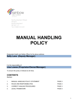
1924 Patent: Lifting Jack by George Lane
Feb. 5 , 1924.
'
6. LANE
1,483,002
LIFTING JACK
Filed’ March ‘19. ~192s
2 Sheets-Sheet 1
I
I
J41?’
.
50 id’
196 Jnueni‘or:
George Lane, I J
,//m W W M
1,483.00;
Patented Feb. 5, 1924.
j$>TATE$ PATENT?!’ QFjFl-QB
stones use or aevGsKEErei-e New Yeas essleeoa To LANE! 1330mm COM?
raw, ‘or rqeeimeersle
103K. A JOINT STOCK ASSOCIMJION OF NEW »_
Lir'rme canon.
“Application
lilarch 19, 1923. Serial ulfl'o. 626,295.
Fig. 3 is a fragmentary view similar to
To all whom it may concern:
‘ Be it‘ known that lf'Gillonen LANE, a citi Fig. 1, but with the parts setior lowering
zen of the’ United States,‘ a‘ndresident' of
Poughkeepsie, the county of D'ut‘chess and ' ‘Fig. Zl'is a fragmentary sectional elevation 60
'
*
State of New ‘York, have‘ invented certain looking toward‘the left Fig. 1.‘ '
iF 1g: v5 is‘ an enlarged detail elevationv
' new“ and" useful ‘improvemeneun Lifting
the
Jacks: 9f this} the following 2's assem
tionl’
My present invention relates to improve~
ments in lifting jacks'ioffthe'
standard.
‘
‘
'
'
‘
"
'
"
show-ling the reversing lever. I
"
ig. 6 is a similar view of the base por
tion or ‘lower end.
'
'
‘
‘
'
Fig. 7 ' is‘a transverse sectional view look
.ing down on the upper pawl and actuating
‘ step
traveling hard‘ re-vei'singi
“The invention" aims "to :provide a_ ‘jack
clever-
‘which’
befposfit'ioiied‘iand removed and
its amen‘ reversed'ilhyi'thié use of'ja relatively
15 ‘long handle, which" jack’ willibe‘strong and
‘ ‘durable aria yer-tic capable of being-more
economically {produced than 1' a'cks“ of" this
type ofwh'ich-I aina'ware."
2O
"
‘
"
4
H
,
,
I.
o
,.
5.5
..
Fig. 8 is a transverse section taken ~just
above the lower'pawl."
"
"
"
"
Fig. ,9' is a detail view of ihe handle .62“ .,
tension,
'\ Figi’lOis
and‘ a view
“
of ' spring modi?cation.
Referring by reference" characters to this
The invention allsoaiins‘to providea jack drawing; the numeral 1 designates the base
which “will he" fecoiioinieal to 'iiiaiiiifacture, of the ack‘, 2 the standard‘. and 3 manning
theoperating par'ts'or which will" not ‘be bar,"which is provided at its upper-end’with
liable’ to "get? ‘but ' of order,‘ ‘and one ‘in which a suitable lifting head ‘indicated at 4. The
both standard is constructed of pressed ‘sheet
the pawls'will"hev spring operated
directions, vgiving a l‘ ?exibility that ' "insures
metal of channel shape vor form, providing
' full'seating‘and at the ‘sametime' possessing parallel walls 2a and 2b, and an edge wall 2“
80
springs of'such size‘andsha‘pe that the ad against which the corresponding edge of the
justment thereof ‘will 'be a delicate‘ mat} lifting bar bears in its rectilinear movement.
fer...
M
..
a
_
.
c
The ‘oppositeedge of the lifting' bar‘ is guid
‘ 'The invention further aims to provide a ed 'in‘the‘ upper end'of thestandard by va
j ack'havinga ‘stand'a'rjlv which may be con ?lling iblock 5'which is disposed between the
structed ofpre's‘sedfshe‘et inetalft’hereby re~ side walls of the standard‘ and which serves
dncing the cost '61:‘ inahi1faot1ire,"hut which to connect and‘ brace said walls, the parts
will be so‘ ?rmly braced’ that it'will be ex
tremely strongzanduduralole."
’
'
“
' ‘
85
being connected b'y‘rive'ts, as indicated at
5?. For guiding the lower‘end of the lift
* The invention "fiirther‘aims to‘ provide ing bar I ‘provide the sidewalls of the stand
such a standard with'arelatilv'ely broad base
giving ampleground support; but which
will be so" strongly constructed as'to with-1
stand "all ofthe strainsencou'ntered in the
40
ard with outwardly pressed portions 2‘‘
which form internal grooves and external
ribs arranged lengthwise of the standard, or
parallel with the lifting barg‘and the lower
rolling orrocking "or 'a' car or: ‘the ‘jack. " end of the standard is' provided with out
With theseand other ‘objects: in view, as wardly s'waged portion or lug 3a which pro- '
will hereafter appear, theinvention includes je'c’ts‘into one of said grooves.
The base 1 is ‘made relatively broad and is
the novel “fe’atureswo'fv construction andar provided
'at its lower end with a ‘plurality
ra‘ng‘e‘meint ‘and combination of parts herein»
45
after described,‘ the nature and " scope’ “of my of slots or openings ‘la through which‘ pass
invention ‘being "de?ned
the 'élainis' ‘ ali
‘?‘lhri'eniliodiinent
deherétdj: of my invention
_,
is illus
trated” _‘
ae'cempanyieg' drawings," in
integral “projecting"tongu'e'sQeiormed on the ‘ "
lower end of the standard. which tongues
after being ‘passedthrough thewslots'; ‘are
‘elin'ohed' over, ' as ‘ shown, to ?rmly connect
the'st’a'ndard‘ toesthe base. ‘ Thebase isfpi‘o
vided ‘’ with~ marginal ‘ portions which “ are
05
‘sides ‘of the. standard‘ against which
110
1v is aside ‘elevation of the. com folded ‘back to" 'fo‘r'm’ upwardly converging
"~Fig.‘2“iis an enlarged‘ sectional elevation wings 1H the‘upper portions of whichare
With ‘the parts 's‘et“ 'ioiwelevatirig" o'nraisin‘g again bent" to ‘bring them ‘into. parallelism
pléteeoidékrw
5
._
..
100
..
g .
15
1,483,002
they abut, these abutting portions being pro 1' and 4, to form a space‘or‘chamberto re
vided with channel portions 1G to receive ceive the said arms and also to receive and
the ribs of the standard, the said abutting form a guide for a floating reversing con
portions and standard walls being secured tact member 16. This'contact‘ member is
together by rivets 6, a filling piece, or spac- in the shape‘ of a plate or bar, slidably
ing means being provided to hold the walls guided in the recess aforesaid at the side
of the standard properly spaced and pressed of the lifting bar, or between the lifting
apart. Preferably, I use a pair of rivets bar and the wall‘ of said recess, and the
and make the ?lling piece in the form of a member 16 is provided with two abutments
piece of sheet metal 7 having its ends bent designed to coact with the ends of the arms UI
around the rivets, as indicated at 7*‘.
11a and 13¢‘. The abutmcnts 16“ and 16"
Articulated upon a pivot pin 8 is an ac may be formed by cutting recesses in from
tuating lever 9 which is adapted to detach~ one edge of the plate or member 16. The
ably and movably receive a handle bar 10. lower recess also provides a second abut- ,
Preferably the actuating lever is provided ment' 160 facing in a reverse direction to SO
with a socket 9a into which the end of the
actuating lever may be slid. The lifting
pawl 11 is pivotally connected to the front
end of the actuating lever, conveniently by
bifurcating the lower end of the pawl and
making the forward end of the actuating
lever of a thickness to ?t within the bifur
abutment
16b.-
1
.
.
i
.
I
A
-
,
A spring arm 17 is arranged to bear up~
wardly against abutment 16c and hold the
reversing member 16 elevated so that its
abutments will successively contact with the a
arms 11a and 13a to reverse the jack in the
manner hereinafter described. Meansare
cation, and providing the overlapping parts provided for forcing the spring arm .1"?
30
with. aligning openings to receive a pivot
pin 12. A. holding pawl 13 is fulcrumed
on a pivot pin 14 supported by the walls of
the standard. These pawls are spring
pressed toward the lifting bar to cause them
normally engage the ratchet teeth 3b
thereof, and the spring means employed for
this purpose preferably takes the form of
a mouse trap spring 15 having its inter
downwardly so‘ as to‘ be out of the path . >
of the arms 11a and 13‘1 during thelelevating
operation of‘ the jack. The spring arm 17
is of a strength exceeding the strength of
the mouse trap spring 15.
¢
90
-
Assuming for example, the ack to be ele
vated and that it is desired to lower it by
a step by step movement, the reversing lever
is, moved from the position shown in Fig.
mediate portion coiled around the piviot pin 52 to that shown in Fig. 8. In this latter
12 between the end of the actuating lever 9 ?gure,~the actuating .lever is showniin its
and one of the walls of the pawl 11 formed upper position, the pawl 11 having been
by the bifurcation referred to, ‘the ends of thrown outward away from the ratchet bar
the spring extending in opposite directions by reason of contact of its arm 11a with
and bearing respectively against the rear abutment 16a. The ‘load is supported at
100
faces of the lifting and ‘holding pawls 11 this time by the holding pawl 13. Down
4:0 and 13.
45
*
In the normal action of the jack in lift
ing, it will be understood that the paWls
remain in contact with the toothed face
of the bar and ride respectively over the
teeth under the relative movement, the
ward movement of the actuating lever now
raises pivot 12 of pawl 11 which allows pawl
11 to beswung towards the ratchet bar by
spring 15, but owing to position of abutment
16“ the pawl cannot move inwardly‘to tooth
engaging position until it has‘ cleared the
spring yielding to permit each pawl to ride previously engaged tooth, whereupon it is
over the teeth.
110
In other words, when the caused to engage the next upwardly suc
actuating lever has been depressed to raise ceeding tooth by reason of its arm 11a being
50
55
the pawl 11, ‘the holding pawl 13 simply raised clear of abutment 16“, at which time
rides over the successive teeth until when ?oating member 16 is prevented from" being
the bar comes to rest the tooth 13 remains raised by its spring 1'? by reason of the
in engagement with the corresponding tooth engagement of pawl 13 with the correspond
of the ratchet bar, and when the actuating ing tooth of the. ratchet bar under the
lever is raised and the lifting pawl 11 is weight of the load andconsequent holding 1
lowered, it likewise rides over the successive of the arm 13‘1 in a'stationary position dur 120:
ing this time. As the actuating lever nears
To’effect the reversing of the jack, I pro the limit of its downward movement, the
vide the pawls 11 and 13 with angularly liftingpawl slightly raises the lifting bar
extended arms 11'"1 and 13“ which are pref which removes the weight of the load from
erably formed integral with the pawls and the holding pawl and the latter 'is- imme
which also preferably extend substantially diately thrown out of tooth engaging posi
teeth.
60
I
I
horizontally forward so as to overlie the side tion by the action of abutment 16b on‘arm
of the lifting bar. ‘ For this purpose the 13a. Raising of the actuating lever now
65
corresponding? side wall of the standard is lowers the lifting pawl and bar.‘ As the
pressed outwardly, as indicated at 2f, Figs. lifting bar and pawl descend, arm 11"- of
l
1,483,002
the pawl contacts with shoulder 163 and
forces the floating member 16 downward
against the tension of spring 17 which al
lows pawl 13 to be moved by mousetrap
spring 15 towards the ratchet bar, the move
ment- being timed so that the pawl clears the
previously engaged tooth and engages the
8
having a notched portion 21a designed to
engage a pin or projection 19b on the look
ing lever. A push on the handle extension
through the link connection rocks the ‘re
versing lever towards the lifting bar, while 70
a pull on the handle extension rocks the re
versing lever in the opposite direction.
Means are provided‘ for holding the revers
next upwardly succeeding tooth. ’ Continued
up and down or pumping movement of the ing lever in either of its two extreme posi
actuating ‘lever repeats the operation above tions and for limiting its movement away
described and results in a step by step down from the lifting bar. To accomplish this I
perferably provide the reversing lever with
ward movement of the lifting bar.
15
20
75
I Itwill he observed that the arms 11a and a substantially segmental portion or shoulder
13a extend substantially horizontally from 19°, having two notches 0 and 0’ designed to
the pivot portions of the pawls or ‘perpen engage ‘a ?xed abutment 8a, which is con
dicular to the pivot ‘axes thereof and thus veniently formed by the head of the pivot
with said pawls constitute bell crank, levers. pin 8 of the actuating lever. The lever 20 is
As the ?oating bar 16 acts vertically the extended suf?ciently to provide a shoulder
force of the abutments is applied as a direct which contacts with the stop 83 to positively
thrust in a line which is tangent to the are limit movement of the actuating lever away
described by the contact point'as each pawl from the lifting bar, (Fig. 5) whereby the
I " thereby secure a handle extension is positively connected
direct thrusting ‘action as distinguished with the actuating lever until the link is
disengaged from its holding position. It is
from a cam or wedge action.
swings on its pivot.
A convenient manner of supporting and necessary to allow some relative movement
operating the spring arm 17 is shown in the between the reversing lever and the locking
drawing. This consists in forming the member or abutment 8a, to allow the latter
spring arm 17 as one arm of a mouse trap to ride out of the recesses 0, c’, and this is
spring which is coiled around a supporting preferably accomplished by providing a
pin 18 carried
.40
or U!
60
65
the stardard, the other slight amount of lost motion between the re— 95
arm 17E’ of the spring bearing against a versing lever and its pivot. To this end the
?xed abutment 19 and holding the spring reversing lever is provided with an elon
under tension. > A. rocking lever 20 is ful gated pivot opening, as indicated at 191.
crumed on the outer face of the standard, A. spring 23 of the mouse trap type is coiled
preferably on a continuation of the pivot around the pivot 18 and has one end bearing
pin 18, this rocking lever being in effect a against abutment 19, its other end bearing
reversing lever- and being provided with against the under side of abutment or pin
a pin or projection 19:‘ extending‘through a 19a and thus tending to force abutment 19a
slot 2K in the side of the standard and de upwardly and allowing it to yield down 105
signed to contact‘ with the upper side of wardly sufficiently for the locking member
'
spring arm 17. Thus if the reversing lever 8a to ride out of the recess.
is swung towards the ratchet bar, the pro-. Ina jack of this character it is desirable
jection 19a will be forced down against the to use a long handle for positioning and re
spring arm 17 carrying the latter out of moving the jack and also for ease in raising 10
position to cooperate with the pawl the load, but it is alsov desirable that this
arms (Fig. 2) while when the lever is handle shall be capable of being folded up
moved away from the ratchet bar, project to make it short enough to be carried in the
tion 19“ will be carried clear of the spring ordinary tool box. I have provided a handle
arm 17 (Fig. 3) which will then be free to attachment or extension of this character
function as above described, for the lowering which will be rigidly held in its extended po
sition, will be locked in its folded position,
operation.
‘
i prefer to operate this locking lever by and at the same time will be easily and quick
a movement of the handle extension 10 rel ly folded and unfolded'without the use of
ative to the actuating lever 9,.and in such a any loose parts. To this end my improved
manner that the handle extension will be handle comprises a portion 10 which enters
locked to the actuating lever so; that. the jack the socket of the actuating lever, and an ex
may be thereby placed in position beneath tension portion 10a which is pivotally con
a car axle and removed therefrom without‘ nectedto the outer end of the portion 10 by
the necessity of crawling under the car, vbut a transverse pivot bolt 25 passing throng
while so locked or held, will be capable of a aligning openings in the overlapping parts.
limited movement relative to the actuating The pivotpin is made longer than the com
lever to effect the rocking of the reversing bined thickness of the two‘ handle members
lever. To this end, the handle extension is and thev projecting portion of the pin is sur
merely slidably held in the socket as afore rounded hv a coil spring 26. which tends to
said’. and. is. rrevidee» with a riveted link 21 press the two members together. ’ The pivot , i’
1%
1,483,002
opening in the member 10“ is set in some to said lifting bar, angularly disposed con~
little distance from the inner end thereof tact arms rigidly connected with said pawls
and said member 10“ is provided with two and extending substantially at right angles
to the pivotal axes of the pawls, a vertically
signed to alternately engage with a locking slidable contact member having spaced abut—
projection 1OX on the member 10, according ments for acting vertically onv the pawl
to whether the handle is folded or unfolded, arms, a spring for forcing said contact
and thus locked in either of these positions. member upwardly into position to contact.
By holding section 10, for example, rigidly with said arms, said spring exerting a force
holes or recesses 10b and 10e which are de
'10
and applying pressure to the member 103 in in excess of the spring means acting on the
the proper direction, the locking projection pawls, and means for de?ecting said spring
will be disengaged from its recess and the from normal position.
extension 1OEL may be swung around on its
4. A lifting jack comprising a standard,
pivot to the proper position, the spring en a lifting bar slidably guided therein, lift
v15 circling the pivot bolt yielding sufficiently to ing and holding pawls cooperating with
permit such disengagement, but normally said lifting bar, spring means normally
holding the parts in locked position.
pressing said pawls into operative relation
If desired I may combine the springs 17 to said lifting bar, angularly disposed con
20
and 23 in one integral structure, as shown tact arms rigidly connected with said pawls
in Fig. 10, in which coil 17 serves to encir adjacent their pivots and overlying the
80
85
cle the pin 18, looped extension 17'y to bear side of the lifting bar, a ?oating member
aganist abutment'19, arm or spring end 17Z at the side of the lifting bar having spaced
to coact with the shoulder 16° of the ?oating abutments for contact with the lower sides
member 16, and arm or spring end 23*‘ to of said arms, yielding means tending nor
25
coact with abutment 19.
mally to force said ?oating member into
Having thus described my invention, position to contact with said arms, and
what I claim is :—
30
35
90
handle controlled means for positioning
1. A lifting pack comprising a standard, said ?oating member so that its abutments
a lifting bar slidably guided therein, lift will be inactive with respect to said arms.
ing, and holding pawls cooperating with
5. A lifting jack comprising a standard,
said lifting bar, spring means normally a lifting bar slidably guided thereby, lift
pressing said pawls into operative relation ing and holding pawls cooperating with
to saidlifting bar, angularly disposed con said lifting bar, spring means normally
95
tact arms rigidly connected with said pawls pressing said pawls into operative relation
and extending at right angles to the piv to said bar, said pawls having contact arms 100
otal axes of the pawls, a ?oating member extending substantially perpendicularly to
having spaced abutments for contact with their pivotal axes and forming therewith
the lower sides of said arms, yielding means bell cranks, a vertically slidable contact
tending normally to force said ?oating member having spaced abutments lying be
neath said contact arms, a spring exerting
member into position to contact with said
arms, and means for positioning said ?oat
ingmember so that its abutments will be
inactive with respect tosaid arms.
105
upward pressure on said slidable member,
and means for relieving said slidable mem—
her from the pressure of the spring.
2. A lifting jack comprising a standard,
6. A lifting jack comprising a standard,
a lifting bar slidably guided therein, lift a lifting bar slidably guided thereby, lift
110
ing and holding pawls cooperating with ing and holding pawls cooperating with
said lifting bar, spring means normally said bar, spring means normally pressing
pressing said pawls into operative relation said pawls into operative relation to said
to said lifting bar, angularly disposed con bar, said pawls having horizontally dis
tact arms rigidly connected with the pivot posed arms overlying the side of the lifting
portions of said pawls and forming there— bar, a vertically movable contact member at
with bell crank levers, a vertically slidable the side of the lifting bar having spaced
contact member having spaced abutments abutments lying beneath said pawl arms,
for cooperating with the pawl arms, a spring springs means for urging said contact mem
for forcing said contact member upwardly ber upwardly into a position to cooperate
into position to contact with said arms, said with said arms, and means for causing said
spring exerting a force in excess of the contact member to be held in inoperative
spring means acting on the pawls, and position. .
means for lowering said slidable member
7. A lifting jack comprising astandard,
out of contact position.
a lifting bar guided thereby, lifting and
3. A lifting jack comprising a standard, holding pawls cooperating with said bar,
85
a lifting bar slidably guided therein, lift~ spring means normally pressing said pawls
ing and holding pawls cooperating with into operative relation to said bar, said
said lifting bar, spring means normally pawls having horizontally disposed arms, a
pressing said pawls into operative relation vertically movable contact member having
115
120
130
1,433,002
abutments positionedbeneath said arms, a
parts being yieldingly mounted, to permit
horizontally disposed spring arm normally disengagement of the locking member and
10
pressing said contact member upwardly, notches, a handle extension detachably and
and means for depressing said spring arm. movably fitting said actuating lever, and
8. A lifting jack comprising a standard, a means detachably connecting said handle ex
lifting bar guided thereby, lifting and hold tension with said reversing lever.
ing pawls cooperating with said bar, spring 12. A lifting jack comprising a standard,
means normally pressing said pawls into a lifting bar, an actuating lever, a lifting
operative relation to said bar, said pawls pawl articulated to said lever, a holding
having horizontally disposed arms, a verti pawl pivoted to the standard, said pawls
cally movable contact member having abut having angularly disposed arms, spring
ments positioned beneath said arms, a hori
70
75
means acting on said pawls, a vertically
zontally disposed spring arm normally vmovable contact member having abutments
15
20
25
pressing said contact member upwardly, a underlying said arms, a pivot pin carried by
lever fulcrumed on the side of the standard the standard, a spring coiled around said
and having a projection overlying said pin having one arm bearing against a ?xed
spring arm, and means for rocking said abutment on the standard and its other arm
horizontally extended and underlying a part
lever.
80
9. A lifting jack comprising a standard, on said contact member, a reversing lever
a lifting bar, an actuating lever pivoted to having an elongated pivot opening engaged
the standard, a lifting pawl articulated to by said pivot pin, said reversing lever hav~
85
said actuating lever, a holding pawl pivoted ing an elongated edge portion provided with
to the standard, said pawls having angularly a pair of spaced recesses, and having also‘ an
extended arms, a vertically movable contact abutment overlying said horizontal spring
member having abutments underlying said arm, a handle extension movably carried by
arms, a horizontally disposed spring arm ar
ranged to raise said contact member, a re
versing lever fulcrumed to the side of the
standard and having a projection overlying
30 said spring arm, and a handle extension de
tachably ?tting said actuating lever and a
link detachably connecting. said handle ex
tension with said reversing lever.
the actuating lever, and a link connecting
said handle extension with said reversing
lever.
r
13. In a lifting jack, a pressed sheet metal
standard having an outwardly pressed por
of its length only, and a lifting bar having
an outwardly swaged portion at its lower
10. A lifting jack comprising a standard, end engaging said groove, the contacting of
a lifting bar, an actuating lever pivoted to said lifting bar extension with the groove
the standard, a lifting pawl articulated to end forming a stop to limit the upward
said actuating lever, a holding pawl pivoted
to the standard, said pawls having angularly
95
tion forming an internal groove for a part
movement of the lifting bar.
100
‘
14. In a lifting jack a standard of pressed
extended arms, a vertically movable contact sheet metal of channel shape having out
40
member having abutments underlying said wardly pressed portions in its'sides forming
105
lengthwise disposed internal grooves and ex
ternal ribs, a relatively broad base to the in
versing lever fulcrumed to the side of the termediate portion of which the lower end
arms, a horizontally disposed spring arm ar
ranged to raise said contact member, a re
45
standard and having a projection overlying of the standard is secured, said base having
said spring arm, and detent means for hold
upwardly and inwardlyv converging wing
110
ing said reversing lever in either reversing portions, the upper edges of which are bent
into parallelism with the side walls of the
or non-reversing position.
11. A lifting jack comprising a standard, standard and secured thereto.
50
15. In a lifting pack, a standard of
a lifting bar, an actuating lever pivoted to
the standard, a lifting pawl articulated to pressed sheet metal‘ of channel shape having
115
said actuating lever, a holding pawl pivoted outwardly pressed portions in its sides form
to the standard, said pawls having angularly ing lengthwise disposed internal grooves
extended arms, a vertically movable contact and external ribs, va relatively broad base to
member having abutments underlying said the intermediate portion of which the lower
60
arms, a horizontally disposed spring arm end of the standard is secured, said base hav
arranged to raise said contact member, a re ing upwardly and inwardly converging
versing lever fulcrumed to the side of the wing portions, the upper edges of which are
standard, and having a projection overlying bent into parallelism with the side walls of
said spring arm, said reversing lever having the standard and secured thereto, the
a portion substantially in the form _of a parallel portions having outwardly pressed
120
125
quadrant having its edge provided with a portions forming grooves to receive the ribs
65
pair of spaced recesses, a locking member of the standard.
In testimony whereof I a?ix my signature.
carried by the standard, said locking mem
ber being adapted to cooperate with said
GEORGE LANE.
recessed edge of the quadrant, one of said
‘ 130


© Copyright 2026