
High Availability Cluster User Guide 3000-hac-v3.1.x-000031-A
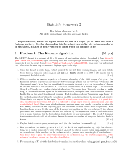
High Availability Cluster User Guide v3.1.x 3000-hac-v3.1.x-000031-A Copyright © 2013 Nexenta® Systems, ALL RIGHTS RESERVED Notice: No part of this publication may be reproduced or transmitted in any form or by any means, electronic or mechanical, including photocopying and recording, or stored in a database or retrieval system for any purpose, without the express written permission of Nexenta Systems (hereinafter referred to as “Nexenta”). Nexenta reserves the right to make changes to this documentation at any time without notice and assumes no responsibility for its use. Nexenta products and services only can be ordered under the terms and conditions of Nexenta Systems’ applicable agreements. All of the features described in this documentation may not be available currently. Refer to the latest product announcement or contact your local Nexenta Systems sales office for information on feature and product availability. This documentation includes the latest information available at the time of publication. Nexenta is a registered trademark of Nexenta Systems in the United States and other countries. All other trademarks, service marks, and company names in this documentation are properties of their respective owners. Product Versions Applicable to this Documentation: Product Versions supported NexentaStor v3.1.x HA Cluster v3.x ii High Availability Cluster User Guide Contents Preface 1 ................................................v Introduction to HA Cluster .................................1 About the Nexenta HA Cluster . . . . . . . . . . . . . . . . . . . . . . . . . . . . . . . . .1 Storage Failover . . . . . . . . . . . . . . . . . . . . . . . . . . . . . . . . . . . . . . . . . .2 Exclusive Access to Storage . . . . . . . . . . . . . . . . . . . . . . . . . . . . . . . . . .2 SCSI-3 PGR for Additional Protection Service Failover . . . . . . . . . . . . . . . . . . . . . . . . . . . . . . . . . . . . . . . . . . .3 Sample Network Architecture Additional Resources 2 . . . . . . . . . . . . . . . . . . . . . . . . . . . . . . . . .3 . . . . . . . . . . . . . . . . . . . . . . . . . . . . . . . . . . . . . . .4 Configuring the HA Cluster .................................5 About Configuring the HA Cluster Prerequisites . . . . . . . . . . . . . . . . . . . . . . . . .3 . . . . . . . . . . . . . . . . . . . . . . . . . . . . . .5 . . . . . . . . . . . . . . . . . . . . . . . . . . . . . . . . . . . . . . . . . . . . .5 Resolving Hostname Conflicts Defining Netmasks . . . . . . . . . . . . . . . . . . . . . . . . . . . . . . . . .6 . . . . . . . . . . . . . . . . . . . . . . . . . . . . . . . . . . . . . .6 Binding the Nodes using SSH Configuring the HA Cluster . . . . . . . . . . . . . . . . . . . . . . . . . . . . . . . . .7 . . . . . . . . . . . . . . . . . . . . . . . . . . . . . . . . . . .8 Adding a Shared Volume to the HA Cluster Importing a Volume to the HA Cluster Removing a Shared Volume 3 . . . . . . . . . . . . . . . . . . . . . . . . . . .9 . . . . . . . . . . . . . . . . . . . . . . . . . . . . . . . . . .9 Heartbeat and Network Interfaces About Heartbeat and Network Interfaces Heartbeat Mechanism . . . . . . . . . . . . . . . . . . . . . . . . . . 11 . . . . . . . . . . . . . . . . . . . . . . . . 11 . . . . . . . . . . . . . . . . . . . . . . . . . . . . . . . . . . . . . 11 Modifying Heartbeat Interfaces . . . . . . . . . . . . . . . . . . . . . . . . . . . . . . . 12 Adding volume heartbeats . . . . . . . . . . . . . . . . . . . . . . . . . . . . . . 12 Adding network heartbeats: 4 . . . . . . . . . . . . . . . . . . . . . . .8 . . . . . . . . . . . . . . . . . . . . . . . . . . . . . 12 Adding serial heartbeats: . . . . . . . . . . . . . . . . . . . . . . . . . . . . . . 13 Configuring Storage Failover . . . . . . . . . . . . . . . . . . . . . . . . . . . . . . . 15 About Configuring Storage Failover . . . . . . . . . . . . . . . . . . . . . . . . . . . . 15 High Availability Cluster User Guide iii Contents Cluster Configuration Data Mapping Information NFS/CIFS Failover . . . . . . . . . . . . . . . . . . . . . . . . . . . . . . . . . . 15 . . . . . . . . . . . . . . . . . . . . . . . . . . . . . . . . . . . . . . 16 . . . . . . . . . . . . . . . . . . . . . . . . . . . . . . . . . . . . . . . . 16 Configuring iSCSI Targets for Failover . . . . . . . . . . . . . . . . . . . . . . . . . . 17 Configuring Fibre Channel Targets for Failover Miscellaneous Options for Fibre Channel 5 Advanced Setup About Advanced Setup . . . . . . . . . . . . . . . . . . . . . . . . . . . . . . . . . . . . . 21 Setting Failover Mode . . . . . . . . . . . . . . . . . . . . . . . . . . . . . . . . . . . . . 21 . . . . . . . . . . . . . . . . . . . . . . . . . . . . . 21 Setting Automatic Failover Mode . . . . . . . . . . . . . . . . . . . . . . . . . . . 22 Adding a Virtual IP Address and Hostname Implementing Miscellaneous Options System Operations Viewing the HA Cluster Status . . . . . . . . . . . . . . . . . . . . . . . . . . . . . . . . 27 Manually Triggering a Failover . . . . . . . . . . . . . . . . . . . . . . . . . . . . . . . . 28 Viewing Support Logs . . . . . . . . . . . . . . . . . . . . . . . . . . . . . . 28 . . . . . . . . . . . . . . . . . . . . . . . . . . . . . . . . . . . . . . 29 Testing and Troubleshooting . . . . . . . . . . . . . . . . . . . . . . . . . . . . . . . 31 Repairing a Broken Cluster Service Replacing a Faulted Node iv . . . . . . . . . . . . . . . . . . . . . . . . . . . 24 . . . . . . . . . . . . . . . . . . . . . . . . . . . . . . . . . . . 27 Verifying Shared Volume Status 8 . . . . . . . . . . . . . . . . . . . . . . . 22 . . . . . . . . . . . . . . . . . . . . . . . . . . . . . . . . . . . . . . 27 About System Operations 7 . . . . . . . . . . . . . . . . . . . . . . 18 . . . . . . . . . . . . . . . . . . . . . . . . . . . . . . . . . . . . . . . . . 21 Setting Manual Failover Mode 6 . . . . . . . . . . . . . . . . . . . . 18 Index . . . . . . . . . . . . . . . . . . . . . . . . . . . . 31 . . . . . . . . . . . . . . . . . . . . . . . . . . . . . . . . . . . 32 . . . . . . . . . . . . . . . . . . . . . . . . . . . . . . . . . . . . . . . . . . . . . . . . . 33 High Availability Cluster User Guide Preface This documentation presents information specific to Nexenta Systems, Inc. products. The information is for reference purposes and is subject to change. Intended Audience This documentation is intended for Network Storage Administrators. It assumes that you have experience NexentaStor and with data storage concepts, such as NAS, SAN, NFS, and ZFS. Documentation History The following table lists the released revisions of this documentation. Table 1: Documentation Revision History Revision Date Description 3000-hac-v3.1.x-000031-A September, 2013 GA Contacting Support • Visit the Nexenta Systems, Inc. customer portal http:// www.nexenta.com/corp/support/support-overview/account-management. Login and browse the customers knowledge base. Choose a method for contacting support: • Using the NexentaStor user interface, NMV (Nexenta Management View): a. Click Support. b. Complete the request form. c. Click Send Request. • Using the NexentaStor command line, NMC (Nexenta Management Console): a. At the command line, type support. b. Complete the support wizard. High Availability Cluster User Guide v Preface Comments Your comments and suggestions to improve this documentation are greatly appreciated. Send any feedback to [email protected] and include the documentation title, number, and revision. Refer to specific pages, sections, and paragraphs whenever possible. vi High Availability Cluster User Guide 1 Introduction to HA Cluster This section includes the following topics: • About the Nexenta HA Cluster • Storage Failover • Exclusive Access to Storage • Service Failover • Sample Network Architecture • Additional Resources About the Nexenta HA Cluster The Nexenta HA (High-Availability) Cluster consists of two NexentaStor appliances and provides a storage volume-sharing service. Neither system is designated as the primary or secondary system. You manage both systems actively for shared storage, although only one system provides the access to a shared volume at a time. After you create a volume on one server and share it with the other server, then, when HAC detects a system failure, it transfers ownership of the shared volumes to the other server in the Cluster pair. HA Cluster provides server monitoring and failover. Protection of services, such as iSCSI, involves cooperation with other modules such as the SCSI Target plugin. An HA Cluster includes: • NexentaStor Appliances Runs a defined set of services and monitors each other for failures. HAC connects these NexentaStor appliances through various communication channels, through which they exchange heartbeats that provide information about their states and the services that reside on them. • Cluster Service A transferable unit that consists of: • Application start-up and shutdown code High Availability Cluster User Guide 1 Introduction to HA Cluster • Network identity and appliance data You can migrate services between cluster appliances manually, or automatically, if one appliance fails. Storage Failover The primary benefit of HA Cluster is to detect storage system failures and transfer ownership of the shared volumes to the alternate NexentaStor appliance. All configured volume services failover to the other server. HA Cluster ensures service continuity during exceptional events, including power outages, disk failures, appliances that run out of memory or crash, and other failures. Currently, the minimum time to detect that an appliance has failed is approximately 10 seconds. The failover and recovery time is largely dependent on the amount of time it takes to failover the data volume on the alternate appliance. Best practices to reduce the failover time include using fewer zvols and file systems for each data volume. When using fewer file systems, you may want to use other properties, such as reservations and quotas, to control resource contention between multiple applications. In the default configuration, HA Cluster implements failover storage services if network connectivity is lost. HA Cluster automatically determines which network device to monitor based on the services that are bound to an interface. It checks all nodes in the cluster, so even if a node is not running any services, HA Cluster continues to monitor the unused interfaces. If the state of one changes to offline, it prevents failover to this node for services that are bound to that interface. When the interface recovers, HA Cluster enables failover for that interface again. Other types of failure protection include link aggregation for network interfaces and MPxIO for protection against SAS link failures. Exclusive Access to Storage You access a shared volume exclusively through the appliance that currently owns the corresponding volume-sharing service. To ensure this exclusivity, HA Cluster provides reliable fencing through the utilization of multiple types of heartbeats. Fencing is the process of isolating a node in an HA cluster, and/or protecting shared resources when a node malfunctions. Heartbeats, or pinging, allow for constant communication between the servers. The most important of these is the disk heartbeat. Generally, additional heartbeat mechanisms increase reliability of the cluster's fencing logic; the disk heartbeats, however, are essential. HA Cluster can reboot the failed appliance in certain cases: • 2 Failure to export the shared volume from the active node to the passive node. This functionality is analogous to Stonith, the technique for fencing in computer clusters. High Availability Cluster User Guide Introduction to HA Cluster In addition, NexentaStor HA Cluster provides a number of other fail safe mechanisms: • When you start a volume sharing service, make sure that the IP address associated with that service is NOT attached to any interface. The cluster automatically detects and reports if an interface is using the IP address. If it is, the local service does not perform the start-up sequence. On disc systems which support a SCSI reservation, you can place a disc before accessing the file systems, and set the system to panic if it loses the reservation. This feature also serves to protect the data on a disc system. HA Cluster also supports SCSI-2 reservations. ! Note: SCSI-3 PGR for Additional Protection HA Cluster employs SCSI-3 PGR for additional protection. SCSI-3 reservation enables write access for multiple nodes to a device and simultaneously blocks access for other nodes. It uses the concept of Write Exclusive Registrants Only. Therefore, only registered systems can perform write operations. You can enable PGR by issuing SCSI reservations on the devices in a volume before you import them. This feature enforces data integrity which prevents the pool from importing into two nodes at any time. Nexenta recommends that you always deploy the HA Cluster with at least one or more heartbeat channels (ethernet or serial).This configuration ensures that the cluster always has exclusive access that is independent of the storage interconnects used in the Cluster. Service Failover As discussed previously, system failures result in the failover of ownership of the shared volume to the alternate node. As part of the failover process, HA Cluster migrates the storage services that are associated with the shared volume and restarts the services on the alternate node. Sample Network Architecture A sample cluster hardware setup includes: • Two x86/64-bit systems with a shared storage (SAS, iSCSI, or FC storage) • Two network interface cards (not mandatory, but good practice) High Availability Cluster User Guide 3 Introduction to HA Cluster The following illustration is an example of an HA Cluster deployment of a Nexenta iSCSI environment. The host server attaches to iSCSI LUNs in the JBOD, which are connected to the Nexenta appliances nodeA and nodeB. The Nexenta appliances use the active/passive function of the HA cluster. NodeA services one group of iSCSI luns while nodeB presents a NAS storage LUN. The following diagram show an example of HA Cluster configuration. CLIENT SIDE NETWORK ETHERNET NETWORK PRIMARY PATH ALTERNATE PATH NEXENTA APPLIANCE: node A NEXENTA APPLIANCE: node B SATA OK 1000GB 7.2 Krpm SATA OK SATA OK 1000GB 7.2 Krpm JBODs 1000GB 7.2 Krpm 1000GB 7.2 Krpm 1000GB 7.2 Krpm 1000GB 7.2 Krpm SATA OK 1000GB 7. 2Krpm 1000GB 7. 2Krpm 1000GB 7. 2Krpm 1000 GB 7.2K rpm SATA OK 1000 GB 7.2K rpm 1000 GB 7.2K rpm 1000 GB 7.2K rpm 1000 GB 7.2K rpm 1000GB 7.2 Krpm SATA OK SATA OK 1000GB 7.2 Krpm SATA OK SATA OK Sun Storage J4400 1000GB 7.2 Krpm SATA OK SATA OK 1000GB 7.2 Krpm SATA OK SATA OK SATA OK 1000 GB 7.2K rpm SATA OK SATA OK SATA OK 1000GB 7. 2Krpm SATA OK SATA OK 1000GB 7. 2Krpm SATA OK SATA OK 1000GB 7. 2Krpm SATA OK SATA OK 1000GB 7.2 Krpm SATA OK 1000GB 7.2 Krpm SHARED VOLUME Additional Resources Nexenta has various professional services offerings to assist with managing HA Cluster. Nexenta strongly encourages a services engagement to plan and install the plugin. Nexenta also offers training courses on high availability and other features. 4 High Availability Cluster User Guide 2 Configuring the HA Cluster This section includes the following topics: • About Configuring the HA Cluster • Prerequisites • Resolving Hostname Conflicts • Defining Netmasks • Binding the Nodes using SSH • Configuring the HA Cluster • Adding a Shared Volume to the HA Cluster • Importing a Volume to the HA Cluster • Removing a Shared Volume About Configuring the HA Cluster You can configure and manage the HA Cluster through the appliance’s web interface, the Nexenta Management View (NMV), or the Nexenta Management Console (NMC). ! Note: This section applies to new installations of HA Cluster. When upgrading, you save and restore the configuration from your previous cluster, so the following sections do not apply. Prerequisites Before configuringthe HA Cluster, complete the following tasks: • Configure two NexentaStor appliances. See NexentaStor Installation Guide. • Connect a shared storage to the NexentaStor appliances (SAS, iSCSI, or FC). High Availability Cluster User Guide 5 Configuring the HA Cluster • Install the HA Cluster plugin on both NexentaStor appliances. See Plugins in the NexentaStor Installation Guide. Resolving Hostname Conflicts There is a name associated with a shared volume service that is referred to as a virtual shared service hostname, or virtual IP address (VIP). The network clients use the virtual hostname to connect to the shared volume . You must make the appliances in the HA cluster group resolvable to each other. This means they must be able to detect each other on the network and communicate. To achieve this, you can either configure your DNS server accordingly, or add records to the host tables on the NexentaStor appliances. The NexentaStor host table (file /etc/hosts) is a simple text file that associates IP addresses with hostnames. Note that you can have only one line per IP address. For each host a single line should be present with the following information: IP_address hostname [aliases...] To configure the shared cluster volume manually: 1. Log in to the NMC on one of the NexentaStor appliances. 2. Type the following to open the /etc/hosts file: nmc:/$ setup appliance hosts 3. Add IP addresses for each node using vim commands: Example: Internet host table ::1 localhost 127.0.0.1 localhost 192.168.60.107 <nodeA nodeA.example.com> loghost 192.168.60.79 <nodeB nodeB.example.com> 192.168.60.22 <virtual_hostname> 4. Repeat Step 1 — Step 3 for nodeB. Defining Netmasks Similar to the host table, you must also define the netmask values for the IP addresses. To configure the shared cluster volume manually, using NMC: 1. Type the following to open the /etc/netmasks file for nodeA: nmc:/$ setup appliance netmasks 2. Add the netmask for each network address: 6 High Availability Cluster User Guide Configuring the HA Cluster Example: 192.168.1.0 192.168.13.0 192.168.0.0 255.255.255.0 255.255.255.0 255.255.0.0 3. Repeat Step 1 — Step 3 for nodeB. Binding the Nodes using SSH Before you configure the SSH bindings, complete the steps in Resolving Hostname Conflicts. You must bind the two HA nodes together with the SSH protocol so that they can communicate. To bind the two nodes, using NMV: 1. Click Settings > Network. 2. In the Network panel, click SSH-Bind. 3. Type the following for the remote server: • Host name • User name The user must have administrative priviledges. • Password 4. Click Bind. 5. Repeat Step 1 — Step 4 on the other node. To bind the two nodes, using NMC: 1. Log in to one of the NexentaStor appliances 2. Type the following: nmc:/$ setup network ssh-bind 3. Type the host name of the NexentaStor appliance that you want to bind. 4. Type the root password. 5. Repeat Step 1 — Step 4 on the other node. 6. To verify that you set up the bindings correctly, type: nmc:/$ show network ssh-bindings High Availability Cluster User Guide 7 Configuring the HA Cluster Configuring the HA Cluster Before you configure the HA Cluster, verify that you completed the steps in Resolving Hostname Conflicts and Binding the Nodes using SSH. You need to configure multiple options for the HA cluster before you can use it successfully. You cannot assign a NexentaStor appliance to more than one HA Cluster. ! Note: To configure an HA cluster, using NMV: 1. On the first node, select Settings > HA Cluster. 2. In the Cluster Settings panel, click Initialize. 3. Type or change the Cluster name. 4. Optionally, type a description. 5. Select Enable Network Monitoring The Cluster monitors the network for nodes. 6. Optionally, select Configure Serial heartbeat. • ! Select the serial ports. Specify serial ports, if the NexentaStor appliances are connected using the serial ports. Note: 7. Click OK. 8. Click Configure. 9. Click Yes. To configure an HA cluster, using NMC: 1. Type: nmc:/$ create group rsf-cluster 2. Follow the onscreen instructions. 3. Verify that you created the group, type: nmc:/$ show group rsf-cluster Adding a Shared Volume to the HA Cluster After you configure the HA Cluster, you must add a shared volume to the volume service. If you do not add a shared volume to the Cluster when you create it, you can add it later. To add a volume to HAC, using NMV: 1. In the Cluster Settings panel, click Volumes. 8 High Availability Cluster User Guide Configuring the HA Cluster 2. Select a volume from the dropdown menu. 3. In the Failover Hostname field, type the failover hostname found in the /etc/hosts file. If the failover hostname does not exist, create one, assign the failover host to an available IP address, and add it to the /etc/hosts file. Example: 192.168.60.22 failover-host 4. Select Primary appliance. 5. Select Heartbeat devices. 6. Select failover interfaces. 7. Click Add this volume to the cluster. 8. Click Confirm. To create a shared service, using NMC: 1. Type: nmc:/$ setup group rsf-cluster <cluster_group_name> shared-volume add 2. Follow the onscreen instructions. Importing a Volume to the HA Cluster You may need to import a shared volume if it is exported. The volume may be exported when you upgrade the NexentaStor appliance or it can be imported on another NexentaStor appliance. To import a volume, using NMV: 1. Click Data Management > Data Sets. 2. In the All Volumes panel, click Import. 3. Click Import for the relevant volume. To import a volume, using NMC: Type: nmc:/$ setup volume import Removing a Shared Volume You can remove a shared volume from the HA Cluster control any time. The remove operation does not delete any data on the volume. The volume remains imported on the active HA Cluster node. Hovewer, the volume becomes unavailable through the failover hostname. High Availability Cluster User Guide 9 Configuring the HA Cluster To remove a shared volume, using NMV: 1. In the Cluster Settings panel, click Volumes. 2. Select the Remove a volume tab. 3. Select a volume. 4. Click . To remove a shared volume, using NMC: 1. Type: nmc:/$ setup group rsf-cluster <cluster> shared-volume <volume> remove System response: Remove shared volume <volume> and restart HA Cluster <cluster> ? (y/n) 2. Confirm the operation by typing y. System response: Removing shared volume <volume>, please wait ... Sep 3 13:47:56 myhost RSF-1[4879]: [ID 702911 local0.alert] RSF-1 cold restart: All services stopped. Waiting for remove operation to complete ... done. 10 High Availability Cluster User Guide 3 Heartbeat and Network Interfaces This section includes the following topics: • About Heartbeat and Network Interfaces • Heartbeat Mechanism • Modifying Heartbeat Interfaces About Heartbeat and Network Interfaces A NexentaStor appliance in the HA Cluster constantly monitors the state and status of the other appliance in the Cluster through heartbeats. Because HA Cluster servers must determine that an appliance (member of the cluster) has failed before taking over its services, you configure the cluster to use several communication channels through which to exchange heartbeats. Heartbeat Mechanism The loss of all heartbeat channels represents a failure. If an appliance wrongly detects a failure, it may attempt to start a service that is already running on another server, leading to so-called split brain syndrome. This can result in confusion and data corruption. Multiple, redundant heartbeats prevent this from occurring. In NexentaStor, VDEV labels for devices in the shared volume perform the heartbeat function. If a shared volume consists of a few disks, NexentaStor uses VDEV labels for one or more disks for the heartbeat mechanism. You can specify which disks. The heartbeat mechanism uses sectors 512 and 518 in the blank 8K space of the VDEV label on each of the shared disks. Though the quorum disk option still remains in the configuration file, Nexenta recommends using the shared VDEV labels. High Availability Cluster User Guide 11 Heartbeat and Network Interfaces HA Cluster supports the following types of heartbeat communication channels: • Disk Heartbeat Accessible and writable from all appliances in the cluster or VDEV labels of the devices in the shared volume. • Network Interfaces The preferred heartbeat connection is a dedicated "cross-over" connection between the nodes. You can also use or add any other interface type (simple, IPMP, aggregate) for additional resiliency. • Serial Links Heartbeat conection using a null-modem serial cable plugged into both NexentaStor nodes. Modifying Heartbeat Interfaces When you define a cluster, you define the heartbeat properties. However, you can modify them later, if needed. A NexentaStor appliance cannot belong to more than one cluster. ! Note: To change heartbeat properties, using NMV: 1. Click Settings > HA Cluster. 2. In Cluster Settings, click Heartbeats. Adding volume heartbeats 1. Click the Volume Heartbeats tab, 2. Right click on a disk and select the vdev. 3. Click Save Settings. Adding network heartbeats: 1. Click the Appliance Heartbeats tab, 2. Right click on Network heartbeats and select Add a network hearbeat. 3. In the Create network heartbeat dialog, type the IP address or a hostname available on a remote NexentaStor appliance. 4. Optionally, click Test. 5. Click OK. 6. Click Save Settings. 12 High Availability Cluster User Guide Heartbeat and Network Interfaces Adding serial heartbeats: 1. Click the Appliance Heartbeats tab, 2. Right click on Serial heartbeats and select Add a serial hearbeat. 3. In the Select serial ports for heartbeat dialog, select serial ports on the local and remote NexentaStor appliances. 4. Click OK. 5. Click Save Settings. To change heartbeat properties, using NMC: 1. Type: nmc:/$ setup group rsf-cluster <cluster_name> hb_properties System response: • Enable inter-appliance heartbeat through primary interfaces?: Yes | No • Enable inter-appliance heartbeat through serial ports?: Yes | No • Proceed: Yes | No 2. Follow the onscreen instructions. High Availability Cluster User Guide 13 Heartbeat and Network Interfaces This page intentionally left blank 14 High Availability Cluster User Guide 4 Configuring Storage Failover This section includes the following topics: • About Configuring Storage Failover • Cluster Configuration Data • Mapping Information • NFS/CIFS Failover • Configuring iSCSI Targets for Failover • Configuring Fibre Channel Targets for Failover About Configuring Storage Failover HA Cluster detects storage system failures and transfers ownership of shared volumes to the alternate NexentaStor appliance. HA Cluster ensures service continuity in the presence of service level exceptional events, including power outage, disk failures, appliance running out of memory or crashing, etc. Cluster Configuration Data When you configure SCSI targets for either FC or iSCSI in a cluster environment, make sure that you are consistent with configurations and mappings across the cluster members. HA Cluster automatically propagates all SCSI Target operations. However, if the alternate node is not available or not configured at the time of the configuration change, problems can occur. By default, the operation results in a warning to the User that the remote update failed. You can also set HA Cluster to synchronous mode. In this case, the action fails completely if the remote update fails. To set the synchronous mode, using NMC: 1. Type: nmc:/$ setup appliance nms property rsf_config_update_synchronous High Availability Cluster User Guide 15 Configuring Storage Failover System response: View or modify NMS property ‘rsf_config_update_synchronous'. RSF-1 Appliance configuration update mode. 1 - Strict Synchronous update across the cluster, 0 - Asynchronous update, if synchronous update fails. Navigate with arrow keys (or hjkl), or CtrlC to exit. 2. Select an appropriate value: • 1 — Strict Synchronous update across the cluster • 0 — Asynchronous update, if synchronous update fails. To protect local configuration information that did not migrate, periodically save this configuration to a remote site (perhaps the alternate node) and then use NMC commands to restore it in the event of a failover. The restore command restores previously saved configuration data that includes: • Target groups • Host groups (stmf.config) • Targets • Initiators • Target portal groups (iscsi.conf) Mapping Information Use SCSI Target to map zvols from the cluster nodes to client systems. It is critical that the cluster nodes contain the same mapping information. Mapping information is specific to the volume and is stored with the volume itself. You can perform manual maintenance tasks on the mapping information using the mapmgr command. NFS/CIFS Failover You can use HA Cluster to ensure the availability of NFS shares to users. However, note that HA Cluster does not detect the failure of the NFS server software. NFS/CIFS settings are volume-level properties that migrate between nodes automatically upon failover. However, settings such as idmap may need to be defined on both nodes HA Cluster does not detect CIFS server failures. 16 High Availability Cluster User Guide Configuring Storage Failover Configuring iSCSI Targets for Failover You can use HA Cluster to failover iSCSI volumes from one cluster node to another. The target IQN moves as part of the failover. Setting up iSCSI failover involves setting up a zvol in the shared volume. ! Note that you perform the process of creating a zvol and sharing it through iSCSI separately from the HA Cluster configuration. Note: If you create iSCSI zvols before marking the zvol’s volume as a shared cluster volume, then when you share the cluster volume as an active iSCSI session, it may experience some delays. Depending on the network, application environment and active workload, you may also see command level failures or disconnects during this period. When you add a shared volume to a cluster which has zvols created as back up storage for iSCSI targets, it is vital that you configure all client iSCSI initiators, regardless of the operating system, to access those targets using the shared logical hostname that is specified when the volume service was created, rather than a real hostname associated with one of the appliances. Note that the cluster manages all aspects of the shared logical hostname configuration. Therefore, do not configure the shared logical hostname manually. Furthermore, unless the shared volume service is running, the shared logical hostname is not present on the network, however, you can verify it with the ICMP ping command. To configure iSCSI targets on the active appliance, using NMV: 1. Click Data Management > SCSI Target. 2. In the zvols panel, click create. 3. Make the zvol block size > 200MB. HAC automatically migrates the newly created zvol to the other appliance on failover. Therefore, you do not have to duplicate it manually. 4. From the iSCSI pane, click iSCSI > Target Portal Groups and define a target portal group. ! Note: It is critical that the IPv4 portal address is the shared logical hostname specified when the volume service was created, instead of a real hostname associated with one of the appliances. HAC automatically replicates the newly created target portal group to the other appliance. To create an iSCSI target and add it to the target portal group, using NMV: 1. Click iSCSI > Targets. This limits zvol visibility from client initiators to the target portal group. The newly created iSCSI target is automatically replicated to the other appliance. High Availability Cluster User Guide 17 Configuring Storage Failover 2. Type a name and an alias. The newly created iSCSI target displays in the Targets page. To create a LUN mapping to the zvol, using NMV: 1. From the SCSI Target pane, click Mappings. This creates a LUN mapping to the zvol for use as backup storage for the iSCSI target. The newly created LUN mapping is automatically migrated to the other appliance on failover. 2. On the client, configure the iSCSI initiator to use both the IQN of the iSCSI target created and the shared logical hostname associated with both the volume service and the target portal group to access the zvol through iSCSI. Failover time varies depending on the environment. As an example, initiating failover for a pool containing six zvols, the observed failover time is 32 seconds. Nodes may stall while the failover occurs, but otherwise recover quickly. See Also: • “Managing SCSI Targets” in the NexentaStor User Guide • SCSI Target FC User Guide Configuring Fibre Channel Targets for Failover As a prerequisite for configuring Fibre Channel targets, change the HBA port modes of both appliances from Initiator mode to Target mode. To change the HBA port mode, using NMV: 1. Click Data Management > SCSI Target Plus > Fibre Channel > Ports. 2. Select Target from the Mode dropdown menu. 3. Once you change the HBA port modes of both appliances from Initiator mode to Target mode, reboot both appliances so the Target mode changes can take effect. Miscellaneous Options for Fibre Channel When using Fibre Channel, you can enable ALUA (Asymmetric Logical Unit Access) mode. In Fibre Channel, devices are identified and accessed by their WWN. Since the WWN is from the HBA that is accessed, HAC needs a method for mapping and presenting LUNs through the FC HBAs in both nodes. ALUA allows HAC to map and present LUNs through the FC HBAs in both nodes, with the node that owns the zvol and volume actively serving data, and the other HBA identifying itself as a "standby path" for each LUN. The proxy daemon that runs on the nodes ensures that when you map a zvol on one node, that HAC automatically maps a standby path on the standby node. 18 High Availability Cluster User Guide Configuring Storage Failover To enable ALUA mode: 1. In the Cluster settings panel, click Advanced. 2. Click Miscellaneous Options tab. 3. Select Enable ALUA mode. See Also: • SCSI Target FC User Guide High Availability Cluster User Guide 19 Configuring Storage Failover This page intentionally left blank 20 High Availability Cluster User Guide 5 Advanced Setup This section includes the following topics: • About Advanced Setup • Setting Failover Mode • Adding a Virtual IP Address and Hostname • Implementing Miscellaneous Options About Advanced Setup This section describes advanced functions of HA Cluster, such as setting the failover mode, adding virtual hostnames and volumes, and other miscellaneous options. Setting Failover Mode The failover mode defines whether or not an appliance attempts to start a service when it is not running. There are separate failover mode settings for each appliance that can run a service. You can set the failover to the following modes: • Setting Manual Failover Mode • Setting Automatic Failover Mode Setting Manual Failover Mode In manual mode, the HA Cluster service does not initiate the failover when it detects a failure. However, it generates warnings when the parallel appliance is not available. If the appliance cannot obtain a definitive answer about the state of the service, or the service is not running anywhere else, the appropriate timeout must expire before you High Availability Cluster User Guide 21 Advanced Setup can take any action. The primary service failover modes are typically set to automatic to ensure that an appliance starts its primary service(s) on boot up. You may want to set the manual failover mode for maintenance. ! Note: Setting a service to manual mode when the service is already running does not stop that service, it only prevents the service from starting on that appliance. To set the failover mode to manual, using NMV: 1. Click Advanced Setup > Cluster Operations > Set all Manual. 2. Click Yes to confirm. ! Note: Before HAC performs an operation, it saves the state of the services in the cluster, which you can later re-apply to the cluster using the restore button. Once HAC restores the service state, HAC clears the saved state. To set the failover mode to manual, using NMC: Type: nmc:/$ setup group rsf-cluster <cluster_name> sharedvolume <volume_name> manual Setting Automatic Failover Mode In automatic mode, the appliance attempts to start the service when it detects that there is no available parallel appliance running in the cluster. AUtomati failover mode is the default setting. To set the failover mode to automatic, using NMV: 1. Click Advanced Setup > Cluster Operations > Set all Automatic 2. Click Yes to confirm. To set the failover mode to automatic, using NMC: Type: nmc:/$ setup group rsf-cluster <cluster_name> sharedvolume <volume_name> automatic To stop all services in the Cluster, using NMV: 1. Click Stop All Services. 2. Click Yes to confirm. Adding a Virtual IP Address and Hostname You can add a VIP, or shared hostname, when you create the Cluster. You can also add additional VIPs later. Additional VIPs provide the access to a shared volume using a different path. To add a virtual IP address, using NMV: 1. In the Cluster Settings panel, click Advanced. 22 High Availability Cluster User Guide Advanced Setup 2. Click Additional Virtual Hostnames. 3. Select a shared volume from the drop-down list. 4. Click Add a new virtual hostname. 5. Type the virtual hostname and netmask. 6. Select the interface for each node. 7. Click Add. 8. If prompted, type the IP address of the failover node. ! Note: Type the IP address that is not in use and that is accessible from both nodes of the HA Cluster. You can add the hostname and IP address pair to the NexentaStor host tables. See Resolving Hostname Conflicts. 9. Click Add. 10.Click Save Settings. 11.Click OK to confirm the modifications. To add a virtual IP address, using NMC: 1. Type: nmc:/$ setup group rsf-cluster <HA Cluster> vips add 2. Select the HA Cluster service. 3. Type a virtual hostname. 4. If you type the IP address or hostname, that one or more HA Cluster nodes cannot resolve, NexentaStor prompts you to modify the local host tables. • If you want to modify the local host tables: a. Type y. b. Type the IP address and host name. • Alternatively, you can configure the DNS server settings. a. Type n. b. Log in to your DNS server and add the host name and IP address pair to the DNS settings. c. Repeat Step 1 — Step 3 and Step 5 — Step 10. 5. Select a network interaface for this node. Nexenta recommends that you configure additional network interfaces rather than specifying the primary network interface. 6. Select network interaface for the remote node. 7. Type the failover netmask. 8. Confirm the settings by typing y. System response: Stop adding VIPs? (y/n) High Availability Cluster User Guide 23 Advanced Setup 9. Type y to finish adding VIPs. 10.Alternatively, type n to add more VIps and repeat Step 1 — Step 9. Implementing Miscellaneous Options Miscellaneous components add an advanced level of control for fine-tuning the HA cluster. To enable miscellaneous components: Select the desired component(s): • Enable ALUA (Asymmetric Logical Unit Access) mode Makes a SCSI target available from both nodes, even though it is physically present on only one node. The target with the node is considered active. The other node is considered passive. When used in conjunction with client side multi-pathing, ALUA ensures target rescanning is not required on failover, and also that the path to the standby node is valid even when not in use, (because the multi-path client continuously checks the state of the standby node and the path to the standby target). 24 High Availability Cluster User Guide 6 System Operations This section includes the following topics: • About System Operations • Viewing the HA Cluster Status • Manually Triggering a Failover • Verifying Shared Volume Status • Viewing Support Logs About System Operations There are a variety of commands and GUI screens to help you with daily cluster operations. There is a set of cluster-specific commands to supplement NMC. Viewing the HA Cluster Status You can view the status of the HA Cluster and heartbeats at any time. To view the HA Cluster configuration, using NMV: 1. In the Cluster Settings panel, click Status. 2. Click the tabs to view Cluster Status and Heartbeat Status. To view the HA Cluster configuration, using NMC: 1. Type: nmc:/$ show group rsf-cluster <cluster_name> Example: nmc:/$ show group rsf-cluster HA-Cluster System response: PROPERTY name appliances VALUE : HA-Cluster : [NodeA NodeB] High Availability Cluster User Guide 27 System Operations machinesigs : {"NodeA":"XXXXXXXXXX","NodeB":"YYYYYYYYYY"} hbipifs : NodeA:NodeB: NodeB:NodeA: netmon : 1 info : Nexenta HA-Cluster generation : 1 refresh_timestamp : 1375745271.30001 type : rsf-cluster creation : Aug 5 16:27:51 2013 SHARED VOLUME: ha-vol svc-ha-vol-shared-vol-name : ha-vol svc-ha-vol-ipdevs : ha-vol NodeA:e1000g0 NodeB:e1000g0 svc-ha-vol-ipdevs-IPv6 : svc-ha-vol-attached-vols : svc-ha-vol-main-node : NodeA svc-ha-vol-inittimeout : 20 svc-ha-vol-runtimeout : 8 svc-ha-vol-mhdc-disable : n svc-ha-vol-monitor : {"NodeA":{"monitor":"","ipdevs":{"e1000g0":""}},"NodeB":{ "monitor":"","ipdevs":{"e1000g0":""}}} svc-ha-vol-resdisks : NodeA:c1t3d0 NodeB:c1t1d0 HA CLUSTER STATUS: HA-Cluster NodeA: ha-vol running auto e1000g0 20 8 NodeB: ha-vol stopped auto e1000g0 20 8 unblocked ha-vol unblocked ha-vol Manually Triggering a Failover You can manually trigger a failover between systems when needed. Performing a failover from the current appliance to the specified appliance causes the volume sharing service to stop on the current appliance, and the opposite actions take place on the passive appliance. Additionally, the volume exports to the other node. To manually trigger a failover, using NMC: Type: nmc:/$ setup group rsf-cluster <cluster_name> failover Verifying Shared Volume Status Verify the status on the shared volume service using NMV or NMC. 28 High Availability Cluster User Guide System Operations To view the status of a shared volume, using NMV: 1. In the Cluster Settings panel, click Status. To view the status of a shared volume, using NMC: Type: nmc@nodeA:/$ show group rsf-cluster System response: HA CLUSTER STATUS: HA-Cluster nodeA: vol1-114 stopped manual unblocked 10.3.60.134 e1000g0 nodeB: vol1-114 running auto unblocked 10.3.60.134 e1000g0 20 8 20 8 Viewing Support Logs Gather the information about HA Cluster event or errors from the HA Cluster log file. To view support logs, using NMV: Click View Log. To view support logs, using NMC: Type: nmc:/$ show group rsf-cluster <cluster name> log High Availability Cluster User Guide 29 System Operations This page intentionally left blank 30 High Availability Cluster User Guide 7 Testing and Troubleshooting This section includes the following topics: • Repairing a Broken Cluster Service • Replacing a Faulted Node Repairing a Broken Cluster Service NexentaStor tracks various appliance components, and their state. If and when failover occurs (or any service changes to a broken state), NexentaStor sends an email to the administrator describing the event. ! During the NexentaStor installation, you set up SMTP configuration and test so that you can receive emails from the appliance. Note: There are two broken states: • Broken_Safe A problem occurred while starting the service on the server, but it was stopped safely and you can run it elsewhere. • Broken_Unsafe A fatal problem occurred while starting or stopping the service on the server. The service cannot run on any other server in the cluster until it is repaired. ! Warning: Manually verify and troubleshoot the volume before marking the state as repaired. Failure to do so could result in cross-mounting of the volume and lead to data corruption. To repair a shared volume which is in broken state, using NMC: nmc:/$ setup group rsf-cluster shared-volume repair <cluster_name> <volume_name> This initiates and runs the repair process. High Availability Cluster User Guide 31 Testing and Troubleshooting To mark a service as repaired, using NMV: 1. Click Settings > HA Cluster. 2. In the Action column, set the action to repaired. 3. Click Confirm. Replacing a Faulted Node NexentaStor provides advanced capabilities to restore a node in a cluster, in case the state changes to out of service. There is no need to delete the cluster group on another node and reconfigure it and all of the cluster services. To replace a faulted node, using NMC: 1. Type: nmc:/$ setup group rsf-cluster <group_name> replace_node After executing the command, the system asks you to choose which node to exclude from the cluster and which new node to use instead. The system checks the host parameters of the new node and if they match the requirements of the cluster group, it replaces the old one. ! Note: 32 Before performing a replace node operation, you must set up the identical configuration on the new or restored hardware, which HA Cluster uses to replace the old faulted node. The new node must be bind to the existing node using SSH. Otherwise, the operation fails. You must also make the serial port heartbeats configuration the same. High Availability Cluster User Guide Index A adding hostname 22 hostname address 22 shared volume 8 virtual IP address 22 additional resources 4 B binding nodes 7 C cluster configuration data 15 configuration data cluster 15 configuring fibre channel failover 18 HA cluster 5, 8 iSCSI Targets failover 17 storage failover 15 D defining netmasks 6 E exclusive access to storage 2 F failover configuring iSCSI Targets 17 NFS/CIFS 16 service 3 storage 2 triggering manually 28 failover mode setting 21 fibre channel failover configuring 18 misc options 18 G guide audience v H HA cluster configuring 5, 8 heartbeat interfaces modifying 12 heartbeat mechanism 11 hostname adding 22 hostname conflicts resolving 6 I implementing misc options 24 M mapping information 16 misc options implementing 24 modifying heartbeat interfaces 12 failover mode 21 shared disk 12 shared volume adding to cluster 8 status 28 SSH binding the nodes 7 storage failover 2 failover configuring 15 support contact v system operations 27 T triggering failover 28 V virtual IP address adding 22 N netmasks defining 6 network architecture 3 sample 3 nexentastor appliances 1 NFS/CIFS failover 16 nodes binding 7 R resolving hostname conflicts 6 RSF-1 cluster service 1 S scsi-2 pgr 3 service failover 3 setting High Availability Cluster User Guide 33 Index This page intentionally left blank 34 High Availability Cluster User Guide Global Headquarters 455 El Camino Real Santa Clara, California 95050 Nexenta EMEA Headquarters Camerastraat 8 1322 BC Almere Netherlands Houston Office 2203 Timberloch Pl. Ste. 112 The Woodlands, TX 77380 Nexenta Systems Italy Via Vespucci 8B 26900 Lodi Italy Nexenta Systems China Room 806, Hanhai Culture Building, Chaoyang District, Beijing, China 100020 Nexenta Systems Japan 〒 102-0083 Chiyodaku koujimachi 2-10-3 Tokyo, Japan Nexenta Systems Korea Chusik Hoesa 3001, 30F World Trade Center 511 YoungDongDa-Ro GangNam-Gu, 135-729 Seoul, Korea 3000-hac-v3.1.x-000031-A


© Copyright 2026