
Lokal fulltext - Chalmers tekniska högskola
Thesis for the Degree of Doctor of Philosophy
VCSELs for High-Speed, Long-Reach, and
Wavelength-Multiplexed Optical Interconnects
Erik Haglund
Photonics Laboratory
Department of Microtechnology and Nanoscience (MC2)
Chalmers University of Technology
Göteborg, Sweden, 2015
VCSELs for High-Speed, Long-Reach, and
Wavelength-Multiplexed Optical Interconnects
Erik Haglund
Göteborg, August 2015
© Erik Haglund, 2015
ISBN 978-91-7597-255-8
Doktorsavhandlingar vid Chalmers Tekniska Högskola
Ny serie 3936
ISSN 0346-718X
Technical Report MC2-315
ISSN 1652-0769
Photonics Laboratory
Department of Microtechnology and Nanoscience (MC2)
Chalmers University of Technology, SE-412 96 Göteborg, Sweden
Phone: +46 (0) 31 772 1000
Front cover illustration: From left to right: a 50 Gbit/s eye diagram, high-speed
VCSELs on a chip, and cross-section SEM image of released free-hanging grating
bars (each bar is around 250 nm wide).
Printed by Chalmers reproservice, Chalmers University of Technology
Göteborg, Sweden, August, 2015
VCSELs for High-Speed, Long-Reach, and
Wavelength-Multiplexed Optical Interconnects
Erik Haglund
Photonics Laboratory
Department of Microtechnology and Nanoscience (MC2)
Chalmers University of Technology, SE-412 96 Göteborg, Sweden
Abstract
The vertical-cavity surface-emitting laser (VCSEL) is the standard light source in
short-reach fiber-optic links in datacenters and supercomputers. These systems use
an enormous number of links, making cost and energy efficiency pressing issues.
GaAs-based 850 nm VCSELs are therefore attractive due to low-cost fabrication, a
small device footprint enabling compact integration into 2-D arrays, and above all,
the capability of high-speed direct modulation at low power consumption. However,
present commercial VCSELs, operating at around 25 Gbit/s over up to 100 m of
multimode fiber, have insufficient speed, energy-efficiency, and reach for future links.
Many of the attractive VCSEL properties stem from their small modal and active
region volumes. The first part of this thesis explores the limits of optical and electrical confinement in high-speed VCSELs by using the shortest possible cavity length,
and positioning the current-confining oxide aperture close to the active region. This
enabled small-oxide-aperture VCSELs with record-high modulation bandwidth of
30 GHz, capable of energy-efficient data transmission at 25-50 Gbit/s with recordlow dissipated energy per bit in the VCSEL of <100 fJ/bit.
High-speed VCSELs are usually transverse multimode with large spectral widths.
This leads to penalties from chromatic and modal fiber dispersion, limiting the feasible transmission distance to around 100 m at 25 Gbit/s, which is too short for
large datacenters. The second part of this thesis demonstrates that VCSELs with
narrow spectral widths, realized using either a small oxide aperture or an integrated
mode filter, can transmit data at high bit rates over much longer distances. VCSELs
with mode filters enabled transmission at 20 Gbit/s over 2000 m, setting a bit-ratedistance product record for directly modulated 850 nm VCSEL links.
To enable higher link capacity, wavelength division multiplexing may be used,
where several channels at different wavelengths are transmitted in the same fiber.
The final part of the thesis presents the design, fabrication, and experimental results
for monolithically integrated 980 nm multi-wavelength VCSEL arrays. By using
high-contrast gratings with different parameters as top mirrors, the VCSEL resonance wavelength may be set in a post-growth process. Lasing over a wavelength
span of 15 nm was realized.
Keywords: vertical-cavity surface-emitting laser, optical interconnect, high-speed
modulation, spectral width, oxide aperture, quasi-single-mode, mode filter, highcontrast grating, wavelength control.
i
ii
List of Papers
This thesis is based on the following appended papers:
[A] E. Haglund, P. Westbergh, J. S. Gustavsson, E. P. Haglund, A. Larsson, “High-speed
VCSELs with strong confinement of optical fields and carriers,” to appear in J. of
Lightwave Technol., vol. 33, no. 24, pp. 1-9, Dec. 2015, (invited paper).
[B] E. Haglund, P. Westbergh, J. S. Gustavsson, E. P. Haglund, A. Larsson, M. Geen,
and A. Joel, “30 GHz bandwidth 850 nm VCSEL with sub-100 fJ/bit energy dissipation
at 25-50 Gbit/s,” Electron. Lett., vol. 51, no. 14, pp. 1096-1098, July 2015.
[C] R. Safaisini, K. Szczerba, E. Haglund, P. Westbergh, J. S. Gustavsson, A. Larsson,
and P. Andrekson, “20 Gbit/s error-free operation of 850 nm oxide-confined VCSELs
beyond 1 km of multimode fibre,” Electron. Lett., vol. 48, no. 19, pp. 1225-1227,
Sept. 2012.
[D] R. Safaisini, K. Szczerba, P. Westbergh, E. Haglund, B. Kögel, J. S. Gustavsson,
A. Larsson, and P. Andrekson, “High-Speed 850 nm quasi-single-mode VCSELs for
extended-reach optical interconnects,” J. Opt. Commun. Netw., vol. 5, no. 7, pp. 686695, July 2013.
[E] E. Haglund, Å. Haglund, P. Westbergh, J. S. Gustavsson, B. Kögel, and A. Larsson,
“25 Gbit/s transmission over 500 m multimode fibre using 850 nm VCSEL with integrated mode filter,” Electron. Lett., vol. 48, no. 9, pp. 517-518, April 2012.
[F] E. Haglund, Å. Haglund, J. S. Gustavsson, B. Kögel, P. Westbergh, and A. Larsson,
“Reducing the spectral width of high speed oxide confined VCSELs using an integrated
mode filter,” Proc. of SPIE, vol. 8276, pp. 82760L1-8, Feb. 2012.
[G] R. Safaisini, E. Haglund, P. Westbergh, J. S. Gustavsson, and A. Larsson, “20 Gb/s
data transmission over 2 km multimode fibre using 850 nm mode filter VCSELs,”
Electron. Lett., vol. 50, no. 1, pp. 40-42, Jan. 2014.
[H] E. Haglund, J. S. Gustavsson, J. Bengtsson, Å. Haglund, A. Larsson, D. Fattal,
W. Sorin, and M. Tan, “Demonstration of post-growth wavelength setting of VCSELs
using high-contrast gratings,” submitted to Opt. Express, Aug. 2015.
iii
Related publications and conference contributions by the author
not included in the thesis:
Journal papers
[I] P. Westbergh, R. Safaisini, E. Haglund, B. Kögel, J. S. Gustavsson, A. Larsson,
M. Geen, R. Lawrence, and A. Joel, “High-speed 850 nm VCSELs with 28 GHz modulation bandwidth operating error-free up to 44 Gbit/s,” Electron. Lett., vol. 48, no. 18,
pp. 1145-1147, Aug. 2012.
[J] P. Westbergh, R. Safaisini, E. Haglund, J. S. Gustavsson, A. Larsson, M. Geen,
R. Lawrence, and A. Joel, “High-speed oxide confined 850-nm VCSELs operating errorfree at 40 Gb/s up to 85°C,” IEEE Photon. Techn. Lett., vol. 25, no. 8, pp. 768-771,
April 2013.
[K] P. Westbergh, E. P. Haglund, E. Haglund, R. Safaisini, J. S. Gustavsson, and
A. Larsson, “High-speed 850 nm VCSELs operating error free up to 57 Gbit/s,” Electron. Lett., vol. 49, no. 16, pp. 1021-1023, Aug. 2013.
Conference presentations and papers
[L] P. Westbergh, E. Haglund, J. S. Gustavsson, Å. Haglund, B. Kögel, and A. Larsson,
“High speed VCSELs for short reach communication,” European Semiconductor Laser
Workshop 2011, Lausanne, Switzerland, Sept. 2011.
[M] A. Larsson, J. S. Gustavsson, Å. Haglund, J. Bengtsson, B. Kögel, P. Westbergh,
R. Safaisini, E. Haglund, K. Szczerba, M. Karlsson, and P. Andrekson, “High speed
VCSELs for optical interconnects,” 24th International Conference on Indium Phosphide and Related Materials 2012, Santa Barbara, CA, USA, paper Th-2C.1, Aug. 2012.
[N] A. Larsson, J. S. Gustavsson, Å. Haglund, B. Kögel, J. Bengtsson, P. Westbergh,
E. Haglund, and P. P. Baveja, “High-speed tunable and fixed-wavelength VCSELs for
short-reach optical links and interconnects,” in Proc. of SPIE, vol. 8276, pp. 82760H1-9,
San Francisco, CA, USA, Feb. 2012.
[O] P. Westbergh, R. Safaisini, E. Haglund, B. Kögel, J. S. Gustavsson, A. Larsson, and
A. Joel, “High-speed 850 nm VCSELs with 28 GHz modulation bandwidth,” European
Semiconductor Laser Workshop 2012, Brussels, Belgium, Sept. 2012.
[P] R. Safaisini, K. Szczerba, E. Haglund, P. Westbergh, J. S. Gustavsson, A. Larsson,
and P. Andrekson, “22 Gb/s error-free data transmission beyond 1 km of multi-mode
fiber using 850 nm VCSELs,” in Proc. of SPIE, vol. 8639, pp. 86390T1-7, San Francisco,
CA, USA, Feb. 2013.
[Q] P. Westbergh, R. Safaisini, E. Haglund, J. S. Gustavsson, A. Larsson, and A. Joel,
“High-speed 850 nm VCSELs with 28 GHz modulation bandwidth for short reach communication,” in Proc. of SPIE, vol. 8639, pp. 86390X1-6, San Francisco, CA, USA,
Feb. 2013.
[R] J. S. Gustavsson, A. Larsson, Å. Haglund, J. Bengtsson, P. Westbergh, R. Safaisini, and
E. Haglund, “High speed 850nm VCSELs for >40Gb/s transmission,” in Optical Fiber
Communiation Conference (OFC) 2013, San Francisco, CA, USA, paper OTh4H.4,
Feb. 2013.
[S] P. Westbergh, R. Safaisini, E. Haglund, J. S. Gustavsson, A. Larsson, and A. Joel,
“High speed oxide confined 850 nm VCSELs operating error-free at 47 Gbit/s at room
iv
temperature and 40 Gbit/s at 85°C,” Conference of Lasers and Electro-Optics (CLEO)
Europe, Munich, Germany, paper CB-7.1, May 2013.
[T] J. S. Gustavsson, A. Larsson, Å. Haglund, J. Bengtsson, P. Westbergh, R. Safaisini,
and E. Haglund, “High-speed, high-temperature VCSELs for optical interconnects,”
in IEEE Photonic Society Summer Topical Meeting Series 2013, Waikoloa, HI, USA,
paper MA2.2, July 2013.
[U] E. Haglund, P. Westbergh, E. P. Haglund, R. Safaisini, J. S. Gustavsson, K. Szczerba,
Å. Haglund, and A. Larsson, “850 nm datacom VCSELs for higher-speed and longerreach transmission,” European VCSEL Day, Lausanne, Switzerland, June 2013.
[V] A. Larsson, P. Westbergh, J. S. Gustavsson, E. Haglund, and E. P. Haglund, “High
speed VCSELs and VCSEL arrays for single and multicore fiber interconnects,” in Proc.
of SPIE, vol. 9381, pp. 93810D1-11, San Francisco, CA, USA, Feb. 2015.
[W] S. Kumari, J. S. Gustavsson, R. Wang, E. P. Haglund, P. Westbergh, D. Sanchez,
E. Haglund, Å. Haglund, J. Bengtsson, N. Le Thomas, G. Roelkens, A. Larsson,
and R. Baets, “Integration of GaAs-based VCSEL array on SiN platform with HCG
reflectors for WDM applications,” in Proc. of SPIE, vol. 9372, pp. 93720U1-7, San
Francisco, CA, USA, Feb. 2015.
[X] E. Haglund, P. Westbergh, J. S. Gustavsson, E. P. Haglund, A. Larsson, M. Geen, and
A. Joel, “High-speed 850 nm VCSEL with 30 GHz modulation bandwidth,” Conference of Lasers and Electro-Optics (CLEO) Europe, Munich, Germany, paper CB-2.4,
June 2015.
Other publications
[Y] E. Haglund, Å. Haglund, P. Westbergh, J. S. Gustavsson, B. Kögel, and A. Larsson,
“Mode-filtered semiconductor lasers enable longer-reach optical interconnects,” SPIE
Newsroom, Oct. 2012.
v
vi
Acknowledgement
There are many who have supported me during the last five years, making this
work possible. I would first like to thank my supervisor and examiner Prof.
Anders Larsson for letting me work in this exciting field, and for his friendly
support, with a door always open for discussions. I would like to thank Åsa
Haglund for cheerfully sharing her vast experience in VCSELs, and also for,
together with Petter Westbergh, giving me an excellent introduction to the
fine art of VCSEL processing. However, no VCSELs would have been fabricated without the outstanding Nanofabrication Laboratory staff, working endlessly to keep our magnificent cleanroom running. I am also grateful to Johan
S. Gustavsson and Jörgen Bengtsson for simulations of VCSELs and HCGs,
Rashid Safaisini for collaboration on difficult projects, Krzysztof Szczerba for
answering any question in the world, Benjamin Kögel for teaching me about
courage, and Emanuel Haglund for discussions about everything from shaving
to VCSELs. My office mates Martin Stattin and Attila Fülöp deserves many
thanks for their support in dealing with problems both large and small. I am
very lucky to work at the Photonics Lab with so many great past and present
Fiber Guys and Opto Dudes, and an excellent secretary in Jeanette Träff. I’m
especially grateful to Tobias, Aleš, and Clemens for many memorable moments.
There would be no HCG-VCSELs without the enthusiasm of Mike Tan, David
Fattal, and Wayne Sorin at HP Labs in Palo Alto. Wayne Sorin is also acknowledged for the HCG reflectivity measurement, David Fattal for HCG simulations, and Prof. Mattias Hammar at KTH for providing the epitaxial 980 nm
HCG test structure.
This thesis is latest step in my, so far, 23 year long education. I would not
have made it this far without great teachers and mentors guiding me along
and inspiring me. I’m especially grateful to Mr. Thomas Walters at Bell
Lane School, London, Jan Stumle at Tingvallagymnasiet, Karlstad, and Tobias Gründl and Christian Grasse, formerly at TU München.
vii
Finally, I want to thank my wonderful family and friends, and my lovely Hanna,
for always being there for me.
The research on high-speed VCSELs was financially supported by the Swedish
Foundation for Strategic Research (SSF) projects LASTECH and MUTOI,
and the European FP7 project VISIT (224211). The high-contrast grating
project was financed by HP Labs. IQE Europe is gratefully acknowledged for
supplying the epitaxial VCSEL material.
Erik Haglund
Göteborg
August 2015
viii
MBE molecular beam epitaxy
MCF multicore fiber
MEMS micro-electric-mechanical
system
MMF multi-mode fiber
MOCVD metal-organic chemical vapor
deposition
Abbreviations
MUX multiplexer
NCU National Central University,
Taiwan
OOK on-off keying
OSA optical spectrum analyzer
PECVD plasma-enhanced chemical
vapor deposition
4-PAM four-level pulse amplitude
modulation
PL photoluminescence
ACC air-coupled cavity
PRBS pseudorandom binary sequence
AOC active optical cable
AR anti-reflection
QW quantum well
ARDE aspect-ratio-dependent etching
RCWA rigorous coupled-wave analysis
BCB benzocyclobutene
RF radio frequency
BER bit error rate
RIE reactive ion etching
BR bit rate
RMS root-mean-square
BTB back-to-back
RT room temperature
BW bandwidth
SCC semiconductor-coupled cavity
CMOS complementary
metal-oxide-semiconductor
SCH separate confinement
heterostructure
DBR distributed Bragg reflector
SEM scanning electron microscopy
DEMUX demultiplexer
SDM spatial-division multiplexing
DFB distributed feedback laser
SMF single-mode fiber
EC extended cavity
SMSR side-mode suppression ratio
EDR energy-to-data ratio
SOI silicon on insulator
FEC forward error correction
TE transverse electric
flops floating-point operations per
second
TM transverse magnetic
TUB Technical University of Berlin
FWHM full width at half maximum
UIUC University of Illinois,
Urbana-Champaign
HCG high-contrast grating
HDR heat-to-data ratio
HPC high-performance computing
VCSEL vertical-cavity surface-emitting
laser
ICP inductively-coupled plasma
VOA variable optical attenuator
IV current-voltage
WDM wavelength-division multiplexing
LED light-emitting diode
WPE wall-plug efficiency
ix
x
Table of Contents
Abstract
i
List of Papers
iii
Acknowledgement
vii
Abbreviations
ix
1 Introduction
1.1 VCSELs in Optical Interconnects . . . . . . . . .
1.2 High-Speed VCSELs . . . . . . . . . . . . . . . .
1.3 VCSELs for Energy-Efficient Data Transmission
1.4 Longer-Reach Optical Interconnects . . . . . . .
1.5 Multiplexing in Optical Interconnects . . . . . .
1.6 Scope and Outline of Thesis . . . . . . . . . . . .
.
.
.
.
.
.
.
.
.
.
.
.
.
.
.
.
.
.
.
.
.
.
.
.
.
.
.
.
.
.
.
.
.
.
.
.
.
.
.
.
.
.
.
.
.
.
.
.
1
2
3
5
8
10
12
2 VCSEL Fundamentals
2.1 History of VCSELs . . . . . . . . .
2.2 Cavity and Mirrors . . . . . . . . .
2.3 Active Region . . . . . . . . . . . .
2.4 Optical and Electrical Confinement
2.5 Spectral Characteristics . . . . . .
2.6 Thermal Properties . . . . . . . . .
3 VCSEL Dynamics
3.1 Intrinsic Dynamics . . . . . . .
3.2 Thermal Limitations . . . . . .
3.3 Parasitic Effects . . . . . . . .
3.4 High-Speed VCSEL Design . .
3.5 High-Speed Characterization .
3.5.1 Small-Signal Modulation
xi
.
.
.
.
.
.
.
.
.
.
.
.
.
.
.
.
.
.
.
.
.
.
.
.
.
.
.
.
.
.
.
.
.
.
.
.
.
.
.
.
.
.
.
.
.
.
.
.
.
.
.
.
.
.
.
.
.
.
.
.
.
.
.
.
.
.
.
.
.
.
.
.
.
.
.
.
.
.
13
14
14
16
17
19
22
. . . . . .
. . . . . .
. . . . . .
. . . . . .
. . . . . .
Response
.
.
.
.
.
.
.
.
.
.
.
.
.
.
.
.
.
.
.
.
.
.
.
.
.
.
.
.
.
.
.
.
.
.
.
.
.
.
.
.
.
.
.
.
.
.
.
.
.
.
.
.
.
.
.
.
.
.
.
.
.
.
.
.
.
.
.
.
.
.
.
.
25
25
29
31
32
34
34
.
.
.
.
.
.
.
.
.
.
.
.
.
.
.
.
.
.
3.5.2
Large-Signal Modulation and Data Transmission . . . .
35
4 Quasi-Single Mode VCSELs
4.1 Small Oxide Aperture . . . . . . . . . . . . . . . . . . . . . . .
4.2 Surface Relief Mode Filter . . . . . . . . . . . . . . . . . . . . .
4.2.1 Effects on Static Characteristics . . . . . . . . . . . . .
37
38
39
41
5 VCSEL Fabrication
5.1 Lithography . . . . . . . . . . . .
5.2 Thin Film Deposition . . . . . .
5.3 Etching . . . . . . . . . . . . . .
5.4 Wet Oxidation . . . . . . . . . .
5.5 High-Speed VCSEL Process . . .
5.5.1 Surface-Relief Processing
.
.
.
.
.
.
.
.
.
.
.
.
.
.
.
.
.
.
.
.
.
.
.
.
.
.
.
.
.
.
43
43
44
45
46
46
48
6 Monolithic Multi-Wavelength HCG-VCSEL Arrays
6.1 Monolithic Multi-Wavelength VCSEL Arrays . . . . . .
6.2 High-Contrast Gratings . . . . . . . . . . . . . . . . . .
6.3 Physics of HCGs . . . . . . . . . . . . . . . . . . . . . .
6.4 Design of Multi-Wavelength HCG-VCSEL Arrays . . . .
6.4.1 Transverse Electrical Confinement . . . . . . . .
6.4.2 Semiconductor-Air Interface . . . . . . . . . . . .
6.4.3 Wavelength-Setting and Threshold Material Gain
.
.
.
.
.
.
.
.
.
.
.
.
.
.
.
.
.
.
.
.
.
.
.
.
.
.
.
.
49
49
51
52
55
56
57
59
7 HCG Fabrication
7.1 HCG Definition . . . . . . . . . . . . . . .
7.2 HCG Dry Etching . . . . . . . . . . . . .
7.3 GaAs/InGaP HCGs for 980 nm VCSELs .
7.4 AlGaAs/GaAs HCGs for 850 nm VCSELs
7.5 HCG-VCSEL Fabrication . . . . . . . . .
.
.
.
.
.
.
.
.
.
.
.
.
.
.
.
.
.
.
.
.
61
62
63
64
66
67
8 HCG-VCSEL Experiments
8.1 Test Structures . . . . . . . . . . . . . . . . . . . . . . . . . . .
8.2 HCG-VCSELs . . . . . . . . . . . . . . . . . . . . . . . . . . . .
8.2.1 Single-Mode Emission . . . . . . . . . . . . . . . . . . .
69
69
71
72
9 Outlook and Future Directions
75
10 Summary of Papers
79
References
85
Papers A–H
.
.
.
.
.
.
.
.
.
.
.
.
.
.
.
.
.
.
.
.
.
.
.
.
.
.
.
.
.
.
.
.
.
.
.
.
.
.
.
.
.
.
.
.
.
.
.
.
.
.
.
.
.
.
.
.
.
.
.
.
.
.
.
.
.
.
.
.
.
.
.
.
.
.
.
.
.
.
.
.
.
.
.
.
.
.
.
.
.
.
.
.
.
.
.
.
.
.
.
.
.
.
.
.
.
.
.
.
.
.
.
.
107
xii
Chapter 1
Introduction
Few people in the industrialized world can imagine their everyday life without
the Internet; we use it almost every waking hour. It has created previously
unimaginable possibilities for keeping in touch with family and friends, searching for information, and sharing of ideas and knowledge. In recent years, the
proliferation of smartphones and the concept of cloud computing has dramatically changed the way we use the Internet. One of the most important effects of
this development is that our computers, tablets, and smartphones are mainly
used as terminals, where we can access information and input commands, while
the data storage and processing is located on servers in massive datacenters
distributed around the world.
As microprocessor clock speeds are not increasing rapidly, the increasing demand of datacenter and supercomputer capacity is solved by parallel operation
of an ever larger number of servers and processor cores [1]. While the fastest
supercomputer in 2002 used 5120 cores (NEC Earth-Simulator, 36 Tflops),
the fastest supercomputer as of August 2015 counts a massive 3,120,000 cores
(Tianhe-2, 34 Pflops) [2]. Meanwhile, the largest datacenters in the world
already span over 100,000 m2 each (equivalent to 12 FIFA standard football
fields) [3, 4]. This up-scaling by parallelization means that present and future
datacenters and supercomputers require an internal network with enormous
capacity. Since copper cables have high attenuation at high frequencies, the
most promising solution is to use fiber-optic links (called optical interconnects)
to connect different parts of the system. The vast majority of these links are
shorter than 100 m in length [5], but as datacenters are growing larger, longer
low-cost high-speed links up to 2 km will be required [6]. Energy-efficient short
links (<1 m) will also be needed when optical links migrate closer to the processors (optical backplanes, on-board, and on-chip interconnects) [7, 8]. Future
1
1. INTRODUCTION
exascale supercomputers, capable of 1 Exaflop per second (Exa=1018 ), are estimated to require an astonishing bidirectional optical interconnect capacity of
400 PB/s [7, 9]. Even if this data was to be transmitted at channel speeds as
high as 40 Gbit/s, a grand total of 160 million channels would be needed for one
exascale supercomputer. The vast interconnect bandwidth required in present
and future systems creates a demand for higher-speed (>25 Gbit/s) and highly
energy-efficient interconnects. This makes GaAs-based vertical-cavity surfaceemitting lasers (VCSELs) well-suited transmitters for optical interconnects,
with advantages such as low-cost fabrication, high-speed modulation at low
power-consumption, small footprint, and high reliability [10, 11].
1.1
VCSELs in Optical Interconnects
A schematic figure of a single-channel optical interconnect, with its different
parts, is shown in Figure 1.1. These are often integrated into active optical
cables (AOCs), which are “plug-and-play” cables with electrical interfaces at
both ends while the electro-optics are fully sealed. Today’s commercial shortreach (<300 m) optical interconnects employ GaAs-based VCSELs emitting
at 850 nm. Most AOCs have several channels bundled together, such that
100 Gbit/s AOCs consist of either ten 10 Gbit/s channels or four 25 Gbit/s
channels transmitted through a ribbon of multi-mode fibers (MMFs), with
arrays of VCSELs and detectors at each end. VCSEL-based links commonly
use direct modulation and on-off keying (OOK), where the laser output is
changed between two fixed levels by modulating the applied voltage.
The MMF used in 850 nm interconnects is more expensive than singlemode fiber (SMF) because of its complex refractive index profile [12]. However, because of the larger core size (50 μm compared to SMF 8 μm), MMF
offers relaxed alignment tolerances, enabling low-cost assembly and packaging
of VCSEL-based transceivers. GaAs pin photodetectors used in 850 nm optical interconnects feature a relatively large active area for efficient coupling
from the large core size MMF, which translates into a larger capacitance and
consequently lower bandwidth than the smaller SMF coupled photodetectors.
0 1 0 11 01 00 1 0
0 1 0 11 01 00 1 0
Input data
Driver circuit
VCSEL
Multimode fiber Photoreciever
Output data
Figure 1.1: Schematic figure of a VCSEL-based optical interconnect link.
2
1.2. HIGH-SPEED VCSELS
This is equivalent to a trade-off between detector responsivity and bandwidth.
The photodetector is one of the limiting factors for both reach and speed of
optical interconnects, making the development of faster and more sensitive
photodetectors imperative.
Today, 850 nm GaAs-based VCSEL technology is used in 95% of all optical
networking applications <1000 m [13]. Depending on application, three standardized data networking protocols dominate the 850 nm interconnect market;
Ethernet (local area networks), Infiniband (high-performance computing, supercomputers), and Fibre Channel (storage area networks). Even though there
are some differences, all work with 10-16 Gbit/s per channel over distances up
to 300-550 m over OM4 MMF [14]. Higher-speed AOCs working at channel
speeds of ∼25 Gbit/s are expected in the very near future for distances up to
100 m [15], and channel speeds up to 50 Gbit/s may be seen towards the end of
this decade [16]. Parallel optical transceivers with arrays of VCSELs and photodetectors, each operating at 25 Gbit/s, will soon realize commercial optical
interconnects with an aggregate capacity of 400 Gbit/s in each direction [15].
1.2
High-Speed VCSELs
Increasing the bandwidth and high-speed transmission properties of GaAsbased VCSELs at 850 nm has been an important research direction since the
early 1990’s [17]. Already in 1997, K. Lear et al. demonstrated VCSELs with
21.5 GHz bandwidth, using an oxide-implanted 850 nm VCSEL [18]. The first
20 Gbit/s operation of 850 nm VCSELs was presented by IBM in 2001 [19]. It
took 7 years before 30 Gbit/s was demonstrated by Finisar in 2008, using an
oxide-confined VCSEL [20]. However, only two years later, P. Westbergh et al.
at Chalmers University of Technology demonstrated 850 nm VCSELs capable
of 40 Gbit/s transmission [21]. These VCSELs also broke the old bandwidth
record, achieving 23 GHz by optimization of the damping characteristics [22].
Since then there has been an impressive development in VCSEL small-signal
modulation bandwidth, and especially high-speed data transmission. In 2013
high-speed VCSELs from Chalmers with 28 GHz bandwidth enabled 57 Gbit/s
at room temperature (RT), and 40 Gbit/s at 85°C [23, 24]. Using driver and
receiver circuits with electronic equalization, the same VCSELs could transmit
at 71 Gbit/s at RT [25], and 50 Gbit/s up to 90°C [26]. This is the fastest
VCSEL-based link to date without the use of forward error correction (FEC).
The newest generation high-speed 850 nm VCSELs from Chalmers is presented
in Papers A and B. By strongly confining optical fields and carriers, a smallsignal modulation bandwidth of 30 GHz was reached, which is currently the
record for conventional VCSELs. Current state-of-the-art bandwidths and
3
1. INTRODUCTION
Table 1.1: Current short-wavelength high-speed VCSEL records using OOK.
Group
.
λ [nm]
BW [GHz]/
BR [Gbit/s]
T [°C]
High bandwidth
30
RT
37
RT
23
85
High bit rate
Chalmers
850
57
RT
TU Berlin
980
46
85
High bit rate (with equalization)
IBM-Chalmers
850
71
RT
IBM-Chalmers
850
50
90
1 with coherent VCSEL array.
Chalmers
UIUC1
TU Berlin
850
980
980
Year
Ref.
2015
2015
2014
Paper B
[27]
[28]
2013
2014
[23]
[28]
2015
2015
[25]
[26]
transmission speeds for high-speed VCSELs are summarized in Table 1.1 at
both RT and 85°C.
Although 850 nm still remains the standard wavelength for commercial
optical interconnects, there is a strong interest in 980-1060 nm GaAs-based
VCSELs. These longer wavelengths have several inherent advantages, such as
highly strained InGaAs quantum wells for higher differential gain and lower
transparency carrier density, superior high-temperature performance due to
deeper quantum wells, and the use of binary GaAs in the distributed Bragg
reflectors (DBRs) for increased electrical and thermal conductivity [29]. In addition, the GaAs substrate is transparent at these longer wavelengths, enabling
bottom emitting devices for flip-chip mounting [30], which is not possible at
850 nm. However, there are also some disadvantages compared to 850 nm VCSELs, such as higher loss in polymer waveguides [31], and higher free-carrier
absorption [20]. Researchers from Technical University of Berlin (TUB) have
in recent years demonstrated impressive results with their 980 nm VCSELs. A
temperature-stable VCSEL design, with optimized resonance-gain offset [32],
enabled bandwidths of 25 GHz at RT, decreasing only slightly to 23 GHz at
85°C [28]. These devices also have the present record for high-temperature data
transmission at 46 Gbit/s. Researchers at NEC and Furukawa in Japan are
at the forefront on ∼1060 nm VCSELs [33–36]. NEC’s ion-implanted tunneljunction VCSELs were actually the first to operate at 40 Gbit/s, already in
2007 [33]. Furukawa presented some of the earliest results on energy-efficient
high-speed data transmission with VCSELs in 2011 [36, 37].
This work concerns only direct-modulation OOK, but higher-level amplitude modulation formats can potentially enable higher bit rates, at the
expense of needing a larger power budget [38]. Four-level pulse amplitude
modulation (4-PAM) transmission using 850 nm VCSELs has been demonstrated up to 60 Gbit/s without the use of FEC [39]. Unconventional VCSEL
4
1.3. VCSELS FOR ENERGY-EFFICIENT DATA TRANSMISSION
structures with coupled cavities for multiple resonance peaks have recently
demonstrated bandwidths exceeding 30 GHz. By tuning the photon-photon
resonance peak, the modulation response can be lifted, enabling bandwidths
of up to 37 GHz [27]. Data transmission experiments at 40 Gbit/s have so far
been presented using this type of devices [40]. Furthermore, there is ongoing
research into utilizing other techniques than intensity modulation to transmit
data, such as polarization oscillation switching of spin-polarized VCSELs [41].
1.3
VCSELs for Energy-Efficient Data Transmission
Today’s widely deployed 10 Gbit/s optical interconnects typically consume
25 pJ/bit [35]. The VCSEL itself typically consumes only a few percent of this
(<1 pJ/bit), with the rest being used by the driver electronics and receiver. To
make future high-speed interconnects for supercomputers and datacenters feasible, the link energy consumption must be dramatically reduced to ∼1 pJ/bit,
also at higher channel speeds [7]. Even lower energies per bit may be needed as
optical links migrate closer to the processors, in for instance on-board and onchip interconnects [1, 8]. The performance of state-of-the-art energy-efficient
VCSEL links is stated in Table 1.2. Researchers at IBM have demonstrated
energy-efficient driver and receiver circuits in 32-nm SOI CMOS, increasing the
VCSEL’s share of the total interconnect power consumption to 30-40% [42].
This makes energy-efficient high-speed VCSELs an important research direction. As seen in Table 1.2, the target performance of 1 pJ/bit was reached at
25 Gbit/s, but already at 35 Gbit/s this almost tripled to 2.7 pJ/bit due to
higher driver and receiver power consumption, and increased VCSEL bias. At
higher bit rates, SiGe BiCMOS circuits with equalization have been used to
demonstrate impressive transmission at 40-71 Gbit/s. However, they consume
quite a lot of energy at ∼25 pJ/bit [25, 43–45]. A significant reduction in the
power consumption of high-bit-rate driver and receiver circuits will be needed
to enable future VCSEL links at ≥40 Gbit/s.
Table 1.2: Energy efficiency of full VCSEL-based links. All results are for back-toback transmission at RT using 850 nm VCSELs.
Group
IBM-Sumitomo
IBM-Sumitomo
IBM-Emcore
IBM-Finisar
IBM-Chalmers
BR [Gbit/s]
Link eff.
VCSEL eff. (% of link)
32-nm SOI CMOS
25
1.0 pJ/bit
396 fJ/bit (40%)
35
2.7 pJ/bit
800 fJ/bit (30%)
130-nm SiGe BiCMOS (with equalization)
40
22.3 pJ/bit
653 fJ/bit (3%)
56
23.7 pJ/bit
245 fJ/bit (1%)
64
26.3 pJ/bit
320 fJ/bit (1%)
Year
Ref.
2013
2013
[42]
[42]
2012
2013
2014
[43]
[44]
[45]
5
1. INTRODUCTION
500
850-980-1060 nm
450
Energy dissipation [fJ/bit]
400
350
Chalmers
Chalmers/IBM
TUB
NCU
Furukawa
NEC
Others
300
IBM (equalization)
250
200
150
Small-oxide aperture
100
Paper B
50
0
10
20
30
40
50
60
70
Bit rate [Gbit/s]
Figure 1.2: State-of-the-art VCSEL dissipated energy per bit for high-speed transmission with 850-980-1060 nm VCSELs. The colors indicate the wavelength, while the
shapes indicate the affiliation. (TUB=Technical University of Berlin, NCU=National
Central University, Taiwan.) [21, 23–25, 28, 34–37, 44, 45, 47–58], and Paper B.
Considering only the VCSEL, it is reasonable to assume that it may consume about 10% (100 fJ/bit) of the mentioned 1 pJ/bit target for the full
interconnect. This requires VCSELs with excellent high-speed properties at
low bias currents, and low resistance for low voltage. A high static wall-plug
efficiency (WPE) is also beneficial, but the WPE is not a good figure of merit
on its own [46]. A VCSEL’s capability of energy-efficient high-speed data
transmission is commonly quantified by the either the energy-to-data ratio
V ·I
,
(1.1)
BR
where V is the voltage, I bias current, and BR bit rate, or the dissipated
heat-to-data ratio
EDR =
HDR =
6
V · I − Popt
= (1 − WPE) · EDR,
BR
(1.2)
1.3. VCSELS FOR ENERGY-EFFICIENT DATA TRANSMISSION
where Popt is the output optical power [48]. Considering only the VCSEL, the
HDR is the more appropriate figure of merit, since the EDR does not take
the WPE into account, while it is obvious that a higher output power would
benefit the receiver energy efficiency. The EDR and HDR are given in fJ/bit
in this work, but may also be stated in the equivalent unit of mW/(Tbit/s).
Figure 1.2 shows the HDR from the most energy-efficient and highest-speed
VCSEL transmission experiments, and the current records at RT and 85°C are
summarized in Table 1.3. Researcher from TUB have shown impressive energyefficient high-speed VCSELs at 850 and 980 nm in recent years, using VCSELs
with small oxide apertures of 2-4 μm [28, 46–48, 54, 56, 59]. Even though
small-oxide-aperture VCSELs do not have the highest WPE (∼20% compared
to ∼30% for larger oxide apertures), they have excellent high-speed properties at low bias currents because of the small active and modal volumes (see
Chapter 3) [46]. The most prominent results from TUB are HDRs of 56 fJ/bit
at 25 Gbit/s and 108 fJ/bit at 40 Gbit/s. While the result at 25 Gbit/s is
still a record, our latest VCSELs enabled sub-100-fJ/bit transmission at 2550 Gbit/s, with 73 fJ/bit at 40 Gbit/s, and even 95 fJ/bit at 50 Gbit/s, see
Table 1.3 and Paper B. This demonstrates that VCSELs are capable of energyefficient operation at 40 and 50 Gbit/s without the use of power-hungry equalization techniques. At 1060 nm, Furukawa has demonstrated energy-efficient
operation with <100 fJ/bit dissipated energy at 25 Gbit/s [35].
As seen in Figure 1.2, the record dissipated energy per bit lies within the
range of 50-100 fJ/bit from 10-50 Gbit/s. Even low bit-rates of 10 Gbit/s have
HDRs similar to the record at 50 Gbit/s. The reason is that HDR is given in
terms of energy per bit; for equal HDR at 25 and 50 Gbit/s, the VCSEL must
therefore consume about half as much power at 25 Gbit/s as 50 Gbit/s. Even
at low bit rates, the VCSEL power consumption must still be high enough to
bias the VCSEL at a reasonable point above the threshold.
Table 1.3: Current record VCSEL HDRs for high-speed data transmission.
Group
λ [nm]
BR [Gbit/s]
TU Berlin
850
25
Chalmers
850
40
Chalmers
850
50
IBM-Chalmers1
850
71
TU Berlin
980
35
TU Berlin
980
38
1 using driver circuits with equalization.
T [°C]
HDR [fJ/bit]
Year
Ref.
RT
RT
RT
RT
85
85
56
73
95
250
139
177
2012
2015
2015
2015
2014
2014
[59]
Paper B
Paper B
[25]
[56]
[54]
7
1. INTRODUCTION
1.4
Longer-Reach Optical Interconnects
Long-reach optical interconnects for ∼500-2000 m currently employ InP-based
1310 nm distributed feedback laser (DFB) and SMF [6]. Even though MMF is
more expensive per meter than SMF, the low-cost fabrication of VCSELs-based
transceivers and energy-efficient direct modulation could still make VCSELbased MMF links justifiable for long-reach optical interconnects by using
850 nm VCSELs.
The launching and propagation of the VCSEL output signal through MMF
is a complex process. First, the coupling of the VCSEL modes into the MMF
is not a trivial problem. Depending on launch conditions such as angle, offset
from fiber center, and spot size, each VCSEL mode can excite several different fiber modes, referred to as mode groups. Second, there are three main
fiber-related effects that may limit the transmission distance over MMF; fiber
loss, chromatic dispersion, and modal dispersion. The simplest, but often
not limiting, is the absorption loss during propagation, which is 2.3 dB/km
at 850 nm for OM4 MMF. However, for commercial implementation of longreach MMF links, it will be important to have a large received power in order
to have an adequate power budget for the link. The separation in wavelength
of the transverse modes emitted by the VCSEL cause a broadening of the signal during propagation in the MMF by chromatic dispersion. In addition, the
different modes in the fiber have different propagation constants, giving rise to
modal dispersion. During modulation, the relative optical power in the VCSEL
modes fluctuate by mode competition. This causes a random fluctuation in
the effects of modal dispersion and possible mode-selective losses and coupling,
collectively referred to as mode-partition noise. In highly multimode VCSEL
links the mode-partition noise is reduced by the averaging over many modes,
but lasers with a few modes can suffer greatly. Due to the absence of other
modes, single-mode lasers do not experience any significant mode-partition
noise. The standard OM3 and OM4 MMFs have optimized graded-index profiles in order to minimize the modal dispersion at 850 nm, making chromatic
dispersion the dominating effect [60].
As a rule of thumb, at 10 Gbit/s, chromatic and modal fiber dispersion
will significantly distort the signal for transmission distances exceeding 300 m
of OM4 MMF, causing inter-symbol-interference and bit errors [61]. At higher
bit rates, the shorter bit slot makes the link even more sensitive to dispersion
effects, and the maximum transmission distance decreases even further. The
highest transmission speed across 100 m of MMF is 43 Gbit/s (60 Gbit/s using
equalization) [23, 45]. In addition, commercial 850 nm AOCs are limited to
100 m at 25 Gbit/s [62]. However, quasi-single-mode VCSELs with reduced
spectral width, and thereby reduced effects of dispersion, may transmit at high
8
1.4. LONGER-REACH OPTICAL INTERCONNECTS
10000
Paper G
Transmission distance [m]
Paper C
1000
Paper D
Technique
Affiliation
Multimode
Mode filter
Small oxide
Photonic crystal
Chalmers
TUB
NCU
UIUC
IBM
Bell Labs
Qu
asi
-sin
gle
-mo
de,
lon
g re
ach
Paper E
Mult
imod
e, hig
h sp
eed
100
10
10
20
30
40
50
60
Bit rate [Gbit/s]
Figure 1.3: State-of-the-art high-speed long-distance transmission using 850 nm VCSELs with OOK and multimode fiber. All devices, except the photonic crystal
VCSEL, are oxide confined, and only the mode filter and photonic crystal VCSELs
have special mode-selective structures. All links perform at bit-error-rate <10−12 ,
except the IBM link where only open eyes are shown. (TUB=Technical University
Berlin, UIUC=University of Illinois at Urbana-Champaign, NCU=National Central
University.) [21, 23, 24, 49, 51, 63–70], and Papers C, D, E and G.
bit rates over much longer distances.
Giaretta et al. [63] and Pepeljugoski et al. [64] demonstrated already in
2000 and 2002, respectively, that 850 nm VCSEL links at >10 Gbit/s over >1
km of MMF are feasible by using low-spectral-width VCSELs. As a matter of
fact, Giaretta held the record for the highest bit-rate-distance product with
28.2 Gbit·km/s (10 Gbit/s over 2820 m) until 2014 (Paper G). Increasing VCSEL bandwidths, and larger datacenters, have sparked an interest in extending
the reach of high-speed (>20 Gbit/s) VCSEL MMF links. The 2011 paper [65]
by Fiol et al. from TUB demonstrating 25 Gbit/s over 300 m of OM3 fiber
started the race. Only two years later researchers from Chalmers University of
Technology (Papers C and D), TUB [51], and University of Illinois, UrbanaChampaign (UIUC) [70] had demonstrated ≥25 Gbit/s links over ≥1 km of
9
1. INTRODUCTION
MMF, see Figure 1.3. This was possible by reducing the spectral width of
recently developed high-speed VCSELs.
The most common approach is to use a small oxide aperture of ∼3 μm,
as used in [51, 66, 68] and Papers C and D. The optical guiding can also be
modified by etching a photonic crystal in high-speed VCSELs as demonstrated
by Tan et al. at UIUC [70]. Photonic crystal VCSELs can have excellent
spectral properties and low resistance, but increased scattering loss reduces
the output power and efficiency. The technique of using a surface-relief mode
filter to reduce the spectral width of VCSELs is applied in Papers E and F,
enabling transmission at 25 Gbit/s over 500 m. A further development of the
mode-filter fabrication process improved this to 25 Gbit/s over 1300 m of OM4
fiber and 20 Gbit/s over 2000 m, setting the still standing bit-rate-distanceproduct record of 40 Gbit·km/s for OOK 850 nm VCSEL links (Paper G). The
mode-filter technique allows for a larger oxide aperture, with potentially lower
differential resistance, and higher output power to compensate for propagation
loss in long-reach links. Shi et al. from National Central University, Taiwan
(NCU), used a combination of mode filtering by Zn-diffusion and small oxide
relief (where the oxidized layer is completely removed for low capacitance)
to achieve quasi-single-mode operation, enabling 14 Gbit/s over 2 km, and
25 Gbit/s over 800 m [49, 67].
Higher-level amplitude modulation formats can potentially enable longerreach transmission, but require a larger power budget [38], or complex circuits
for FEC. 4-PAM has been demonstrated at 12.5 Gbit/s over 600 m of fiber
[71], and 48.7 Gbit/s over 200 m using FEC [72]. The current record bit-ratedistance-product at 850 nm is 107.6 Gbit·km/s, and was achieved using discrete
multitone modulation and FEC [73], while we hold the record for direct modulation OOK (Paper G). Future long-reach interconnects may also use VCSELs
at 980 and 1060 nm, which have the advantage of significantly smaller loss and
chromatic dispersion in the silica used in the optical fibers [74]. While the standardized OM4 MMF is optimized for a low modal dispersion around 850 nm,
fiber optimized for higher modal bandwidth, broader wavelength spans, and
longer wavelengths are currently being developed [75, 76]. Another competing
technology is longer-wavelength VCSELs at 1310 or 1550 nm, where the use of
SMF avoids most of the effects of dispersion. Directly modulated InP-based
1550 nm VCSELs have shown close-to error-free transmission at 40 Gbit/s
over 1 km of SMF [77].
1.5
Multiplexing in Optical Interconnects
Besides higher single-channel speed, energy-efficiency, and longer-reach, there
is an additional need for a denser integration of transceivers and fibers. Supercomputers are already approaching the point where there is no room for
10
1.5. MULTIPLEXING IN OPTICAL INTERCONNECTS
VCSEL array
PD array
MUX
Waveguide
DEMUX
Figure 1.4: Simple schematic figure of a 4-channel VCSEL-based WDM optical interconnect.
any more interconnect ports on the switch circuit boards, and Gbit/s/mm
(of edge space) or Gbit/s/mm2 are becoming important figures of merit [78].
Some form of multiplexing of the interconnect channels could be the solution.
Although AOCs already use a crude form of spatial-division multiplexing with
VCSEL/detector arrays and fiber ribbons, everything can be made smaller by
using multicore fibers (MCFs) with several closely spaced cores in one fiber.
Dense VCSEL arrays, with a circular layout fitting to a 6-core MCF, have
recently demonstrated transmission at 240 Gbit/s (6x40 Gbit/s), without any
cross-talk penalty [79, 80].
Another solution is to use wavelength-division multiplexing (WDM) to
transmit several channels at different wavelengths in each fiber core, see Figure 1.4. This could enable the interconnect capacity needed for future supercomputers without needing an unfeasible number of fibers [7]. In addition,
since MMF is more expensive per unit length than SMF, WDM could also make
short-wavelength interconnects cost-effective for longer distances (∼500-1000+
m) [6, 78]. Short-wavelength WDM for optical interconnects faces numerous
technological challenges, foremost the need for energy-efficient, low-cost, and
small-footprint VCSEL arrays, and low-loss multiplexers (MUX) and demultiplexers (DEMUX). Demultiplexing is a major challenge since optical interconnects must operate from room temperature to 85°C without active cooling,
leading to a thermal wavelength drift of the VCSELs of around 4 nm (see
Section 2.6). WDM links have been demonstrated using short-wavelength VCSELs with different emission wavelengths fabricated from different wafers [81,
82]. However, this complicates the packaging of the transceivers [83]. WDM in
optical interconnects would greatly benefit from the development of monolithically integrated multi-wavelength VCSEL arrays, but these are intrinsically
difficult to realize, as the resonance wavelength of the VCSEL cavity is set dur11
1. INTRODUCTION
ing the epitaxial growth. This is further discussed in the second part of this
thesis that demonstrates multi-wavelength VCSEL arrays using high-contrast
gratings (HCGs). Eventually, transmission over a ribbon of MCFs, with several wavelengths in each core, using high-speed VCSELs, and advanced drivers
and receivers, could enable 10’s of or even 100 Tbit/s capacity in a single AOC.
As of today, the only commercial short-wavelength WDM product on the
market is Cisco’s 40 Gbit/s BiDi transceivers that transmits counter-propagating wavelengths at 832 and 918 nm in each fiber using VCSELs fabricated
from two different wafers [84]. Using a fiber pair, 2x20 Gbit/s is transmitted
in each direction for a total bi-directional capacity of 40 Gbit/s. The broad
commercial breakthrough for short-wavelength WDM is yet to come, but there
is significant industrial interest in short-wavelength coarse WDM, and WDM
in the 860-1100 nm range is currently being discussed in the IEEE 400 Gigabit
Ethernet Task Force [85].
1.6
Scope and Outline of Thesis
The focus of this work has been on several important aspects of VCSELs for
future optical interconnects. The first part concerns conventional 850 nm VCSELs for longer-reach and energy-efficient data transmission at high data rates.
Chapter 2 introduces the VCSEL fundamentals. It is followed by Chapter 3
with a more detailed discussion on VCSEL dynamics and high-speed VCSEL
design. Chapter 4 describes the two different quasi-single-mode VCSEL approaches used to enable longer-reach transmission; a small oxide aperture or
an integrated mode filter. The VCSEL fabrication methods are described in
Chapter 5. The second part of the thesis presents the design, fabrication, and
experimental results for 980 nm multi-wavelength VCSEL arrays using HCGs.
Chapter 6 describes the basics of HCGs and the design of HCG-VCSEL multiwavelength arrays. The grating fabrication process is discussed in Chapter 7,
followed by experimental results in Chapter 8. An outlook and future directions, for both parts, are provided in Chapter 9. The results from the work on
which this thesis is based are finally presented in the appended Papers A-H,
which are summarized in Chapter 10.
12
Chapter 2
VCSEL Fundamentals
As the name indicates, vertical-cavity surface-emitting lasers (VCSELs) emit
light normal to the surface by lasing in a vertical cavity, as seen in Figure 2.1a.
The cavity is formed by two highly reflective DBRs (∼99.5%), with a forward
biased pn-junction sandwiched between them providing optical gain. In contrast to the VCSEL, the earlier developed edge-emitting Fabry Perot laser has
a horizontal resonator with cleaved semiconductor-air facets acting as mirrors,
see Figure 2.1b. This means that the wafer must be cleaved to enable testing
and screening, while VCSELs may be tested on-wafer during production and
integrated into 2D arrays. VCSELs are sometimes referred to as micro-cavity
lasers and have several significant advantages because of their small cavity
cleaved facets
p-contact
p-contact
p-doped
p-DBR
n-DBR
substrate
oxide layer
active region
n-contact
n-doped
n-contact
active region
(a)
(b)
Figure 2.1: (a) Cut-through VCSEL sketch. (b) Edge emitting stripe laser.
13
2. VCSEL FUNDAMENTALS
size, such as low threshold currents and excellent high-speed properties at low
power consumption.
2.1
History of VCSELs
The concept of a vertical-cavity semiconductor laser was first proposed in
1977 by Professor K. Iga from Tokyo Institute of Technology, who two years
later also demonstrated the first VCSEL, lasing under pulsed operation at
77 K [86, 87]. The first VCSEL more resembled a “vertical edge emitter” with
a relatively long cavity and metal-coated mirrors. The first reports on room
temperature operation of VCSELs were published in 1989 [88, 89]. During the
1990’s VCSEL research really took off and the first commercial VCSELs came
on the market in the middle of the decade. VCSEL-based short-reach fiberoptic links for data communication were introduced in 1996 [90]. Today 850 nm
GaAs-based VCSEL technology is extensively utilized in short-reach optical
communication links, with 95% of all optical networking applications <1000 m
using multimode fiber and 850 nm VCSELs [13]. The largest volume market
for VCSELs is, however, in optical computer mice where 850 nm VCSELs are
used to track movement on uniform surfaces with higher resolution and speed
than the earlier light-emitting diode (LED) optical mice [17]. In 2013, the
total VCSEL production was around 100 million devices per year, with the
price of a computer-mouse 850 nm VCSEL approaching $0.10 [17]. VCSEL
production output is increasing, with larger wafer sizes being used to scale up
production. In March 2014 IQE delivered the first 6" epitaxial VCSEL wafers
which can accommodate up to 300,000 VCSELs per wafer [91].
2.2
Cavity and Mirrors
The distributed Bragg reflector (DBR) mirrors comprise a stack of alternating
high and low refractive index material, where the light is partially reflected
at each interface. If the optical thickness of each layer equals a quarter wavelength, this wavelength will experience the Bragg condition, meaning that all
reflections add up in phase leading to a large reflection for the whole stack, see
Figure 2.2a. The peak reflectivity depends on the number of DBR pairs and
the refractive index difference Δn between the high- and low-index material,
while the width of the reflection stopband mainly depends on Δn [92]. DBRs
are commonly fabricated using either dielectric or epitaxial material systems.
Dielectric DBRs may achieve a high reflectivity with <10 pairs due to the
high index contrast (e.g. SiO2 /TiO2 with Δn = 0.90 at 850 nm [93]), while
epitaxial DBRs need ∼20-30 pairs because of the lower index contrast (e.g.
Al0.90 Ga0.10 As/Al0.12 Ga0.90 As with Δn = 0.46 [94]). On the other hand epitaxial DBRs can be doped and often function as current spreaders to achieve
14
1
1
0.8
0.8
Reflectivity
Reflectivity
2.2. CAVITY AND MIRRORS
0.6
0.4
0.2
0
750
0.6
0.4
0.2
800
850
900
Wavelength [nm]
950
0
750
(a)
800
850
900
Wavelength [nm]
950
(b)
Figure 2.2: Calculated reflectivity spectra for (a) a VCSEL top DBR with 23 pairs
of Al0.90 Ga0.10 As/Al0.12 Ga0.88 As and (b) a full VCSEL cavity. The single narrow
longitudinal resonance is seen at 845 nm.
a uniform injection of carriers into the active region. For the mirror where no
transmission is required, a hybrid DBR may be used where the DBR is covered
with gold or copper to increase reflectivity. The metal may also function as
a heat sink and a contact for current injection. A completely different type
of mirror, based on a high-contrast grating (HCG), is used in the second part
of this thesis (see Chapter 6). GaAs-based VCSEL designs commonly feature
epitaxial DBRs in the mature AlGaAs material system.
The VCSEL has a short cavity, of length Lcav , sandwiched between the
two DBRs. However, the effective cavity length Lef f is longer, due to the
penetration1 of the optical field into the DBRs [92] (Figure 2.3). The longitudinal resonance of the VCSEL cavity is set by the phase condition; that the
optical field must repeat itself after one round-trip in the cavity. Therefore,
twice the effective optical length Lef f nef f must equal an integer number m of
wavelengths λ0 according to
2Lef f nef f
.
(2.1)
m
Because of the short cavity length, only one longitudinal mode falls within
the gain bandwidth, making the device inherently single longitudinal mode
(though usually not single transverse mode), see Figure 2.2b.
2Lef f nef f = mλ0 ⇒ λ0 =
1 For penetration depths into the top and bottom DBRs of LT and LB , the effective
p
p
B
cavity length is Lef f = LT
p + Lcav + Lp .
15
Refractive index
2. VCSEL FUNDAMENTALS
top DBR
3.6
QWs
bottom DBR
3.4
3.2
3
3.6
Relative intensity
98% oxide layers
ox.
QWs
3.4
3.2
3
0
1
2
3
4
2.9
3
5
3.1
3.2
6
3.3
7
Depth [μm]
Figure 2.3: Refractive index profile and simulated standing wave of the optical field
inside a VCSEL cavity with a cavity length of 3/2-λ, and a double oxide layer above
the active region. The inset shows the overlap of the standing wave with the quantum
wells (QWs) and the nearest oxide layer (ox.). The substrate is to the right.
2.3
Active Region
The active region provides the optical gain. During lasing the modal gain must
balance the optical losses according to
1
1
1
ln T B ,
gth =
(2.2)
αi +
Γ
2Lef f
Rm Rm
where gth is the threshold gain, Γ the optical confinement factor representing
the fraction of the standing wave that overlaps with the active region, αi the
internal optical loss (due to free-carrier absorption and diffraction loss), and
T
B
and Rm
are the top and bottom mirror reflectivities. In semiconductor
Rm
lasers the optical gain by stimulated emission is achieved by injecting carriers into a forward biased pn-junction. Electrons and holes accumulate in the
conduction and valence band respectively, which under high enough injection
gives rise to a population inversion and thereby optical gain. The first semiconductor laser, demonstrated in 1962, had an active region consisting of a
GaAs homojunction and could only operate in pulsed mode at 77 K because
of the high band-to-band absorption [95]. Today the active region usually
consists of a pin-heterojunction with quantum wells (QWs) situated in the
lower-bandgap intrinsic layer. The QWs trap the carriers, providing a high
16
2.4. OPTICAL AND ELECTRICAL CONFINEMENT
carrier density and a good spatial overlap between the electron and hole wave
functions. Since the stimulated emission process is related to the optical field
strength, the QWs are placed at an antinode of the optical field to achieve a
high gain, see Figure 2.3. State-of-the-art high-speed 850-1060 nm VCSELs
use strained InGaAs QWs which reduces the density of states, meaning that
fewer carriers are required to reach a certain gain (i.e. a larger differential
gain) [96]. GaAs-based VCSELs with highly strained InGaAs QWs have been
demonstrated up to ∼1300 nm [97], but beyond ∼1060-1100 nm the increasing
QW strain leads to concerns regarding reliability.
2.4
Optical and Electrical Confinement
The DBRs confine the optical field in the longitudinal direction (Figure 2.3),
but it must also be confined in the transverse direction. Furthermore, the
electrical current must be confined to pump only active material overlapping
with the lasing modes. In most VCSEL designs the electrical and optical confinement originate from the same feature. The first VCSELs consisted of an
etched air post mesa, see Figure 2.4a. The refractive index step from semiconductor to air provides index guiding, confining the optical field in the transverse direction. Although simple, this design has several issues such as high
thermal resistance because of the surrounding air, large scattering losses from
rough sidewalls, and trouble with placing large enough top contacts for low
resistance while avoiding absorption losses from the metal. A further development is the buried heterostructure VCSEL seen in Figure 2.4b. By regrowing semi-insulating semiconductor material around the etched mesa, problems
with thermal resistance and losses are avoided, but the regrowth process is
challenging. The first commercial VCSELs instead used proton implantation,
see Figure 2.4c. Protons are implanted deep into the top DBR, making the
material insulating and forming the current aperture. The implanted material
does not form a direct index step for transverse optical confinement. However, as the center of the waveguide heats up during operation, the refractive
index increases, creating a refractive index gradient. This effect, referred to
as thermal lensing, confines the optical field, but also leads to bias-dependent
unstable modal properties. In addition, scattering of the protons during implantation, due to the large penetration depth into the top DBR, makes it
difficult to fabricate small-aperture devices.
Stable modal properties are obtained by including a built-in index step that
is sufficiently large compared to thermal lensing, gain guiding, and the plasma
effect (decreasing refractive index with increased carrier concentration). One
approach is to use a selectively oxidized layer forming an oxide aperture, see
Figure 2.4d. A high Al-content layer (usually Al0.98 Ga0.02 As) is positioned in
17
2. VCSEL FUNDAMENTALS
air post
(a)
oxide
aperture
(d)
proton implantation
regrowth
(b)
photonic crystal
(e)
(c)
tunnel junction
(f)
Figure 2.4: Different electrical and optical confinement methods: (a) etched air post,
(b) regrown mesa, (c) proton implantation, (d) oxide aperture, (e) photonic crystal
and (f) buried tunnel-junction.
the DBR close to the active region. When the etched mesa side is exposed to
hot water vapor, this layer will oxidize to form an insulating oxide with reduced
refractive index. This creates a current aperture that simultaneously provides
the transverse optical guiding. The oxidation rate is strongly dependent on the
Al-content, and the highest Al-content layer will therefore form the smallest
oxide aperture [98]. To avoid scattering losses and too large index guiding,
the oxide layer is usually positioned close to a node of the optical field [99],
see Figure 2.3. Multiple oxide layers may be used in order to reduce mesa
capacitance to mitigate parasitic bandwidth impairments (as further discussed
in Section 3.3). Oxide-aperture VCSELs are the most common GaAs-based
VCSELs today, and it is also the confinement scheme used in this work.
Lateral current spreading and diffusion in the region between the oxide
aperture and QWs can lead to carrier leakage, accompanied by a reduction of
the internal quantum efficiency2 and an increased threshold current. A strong
lateral confinement of carriers is therefore desired for energy-efficient VCSELs.
2 The
18
portion of injected carriers that recombine by stimulated emission in the QWs.
2.5. SPECTRAL CHARACTERISTICS
Since holes have lower mobility than electrons, the oxide aperture is typically
placed on the p-side to confine the slower holes, as this also prevents electrons
from spreading outwards due to the requirement of charge neutrality. Current
spreading can be reduced by using un-doped intrinsic material between the
oxide aperture and the QWs. This will not have a negative impact on the
carrier transport into the QWs if a properly designed short separate confinement heterostructure (SCH) is used [100]. Current spreading can be especially
troublesome if there is any doped material between the oxide aperture and the
QWs [24]. A strong confinement of the injected carriers is demonstrated in Paper A by positioning the oxide layers as close to the QWs as possible; in the first
field minima of the standing wave on either side of the QWs. This approach
has previously demonstrated low current spreading and diffusion [101]. The
resulting high internal quantum efficiency and low threshold currents enabled
high-speed transmission at record-high energy efficiencies (Paper B).
Decoupling of the electrical and optical confinement, in order to tailor
the optical properties of the VCSEL waveguide, can be achieved by etching
a 2D photonic crystal into the top DBR of an oxide-confined or proton implanted VCSEL, see Figure 2.4e. In addition to increased design and processing
complexity, the photonic crystal structure increases optical scattering losses,
leading to lower output power and larger threshold current [17]. For longwavelength InP-based VCSELs emitting at 1.3 and 1.55 μm, a buried tunnel
junction is used for electrical and optical confinement since no high-quality
oxide exists in this material system, see Figure 2.4f [102]. This technique
is not commonly used for electrical and optical confinement in GaAs-based
VCSELs because of the difficulty to design effective tunnel junctions, the complex regrowth process required, and the excellent properties of oxide-confined
VCSELs.
2.5
Spectral Characteristics
High-speed VCSELs usually have the shortest possible cavity lengths of 1/2-λ
or 3/2-λ, since this enhances the modulation bandwidth (Section 3.1). Because
of the short cavity, VCSELs are inherently single longitudinal mode as only
one longitudinal mode falls within the gain bandwidth. However, due to the
large lateral dimensions (oxide aperture diameter ≥ 10λ), the VCSEL cavity
often supports several transverse modes. The spectral characteristics of the
VCSEL can be analytically investigated using an effective index method [103],
where the radial refractive index step is modeled as a parabolic refractive index
profile according to
19
2. VCSEL FUNDAMENTALS
2
n (r) =
n2c (1 − 2Δr2 /a2 )
n2s = const
,r≤a
,r>a
with
Δ=
nc − ns
n2c − n2s
≈
(2.3)
2n2c
nc
where r is the radial distance, a the radius of the oxide aperture, nc the core
effective refractive index, and ns the effective index of the surrounding oxide
region. It should be noted that although Equation 2.3, strictly speaking, describes a thermally guided VCSEL (e.g. an proton-implanted VCSEL), it may
be used to approximate an oxide-confined VCSEL [17, 103]. The advantage is
that this index profile yields analytical expressions for the spectral characteristics, which are useful for understanding the VCSEL modal properties. By
solving the wave equation in this circular symmetric structure, the near-field
intensity of the transverse modes becomes
2r2
ω02
l (l)
Lp−1
2 −2r2
Slp (r, Φ) ∝ |Elp (r, Φ)| ∝
exp
,
ω02
sin2 (lΦ)
(2.4)
where E is the optical field strength, ω0 the 1/e2 radius, Llp−1 the lth generalized Laguerre polynomial of order (p − 1), and Φ the azimuthal angle. The
modes are referred to as linearly polarized LPlp modes with intensity distribution as shown in Figure 2.5. For l > 0 the sin and cos factors represent
two different orthogonal states rotated 90◦ /l with respect to each other. Furthermore, every mode has two orthogonal polarization states with the electric
field oscillating perpendicular to the propagation direction. Therefore, the
Gaussian-shaped fundamental mode LP01 has two polarization states, while
the higher order modes with l > 0 have four states per LPlp mode. The
wavelength λlp of mode LPlp differs the fundamental longitudinal mode λ0 as
√
Δ λ0
,
(2.5)
λlp = λ0 1 − (2p + l − 1) √
2π nc a
2
2r2
ω02
cos2 (lΦ)
which shows that modes with the same mode index m = 2p + l − 1 have the
same emission wavelength [103]. From Equation 2.5 the mode spacing between
adjacent mode index groups is
√
√
Δ λ20
Δ
∝
,
(2.6)
Δλ = |λm − λm+1 | = √
Dox
2π nc a
where Dox = 2a is the oxide aperture diameter. The order and spacing of
the modes agree well with the measured spectrum and near-field images in
20
2.5. SPECTRAL CHARACTERISTICS
01
11
21
31
41
02
12
22
32
42
Figure 2.5: Transverse intensity distributions of the lowest order LPlp modes plotted
from Equation 2.4. LP11 and LP12 exemplify the rotated polarization states (cos
and sin) which exist for l > 0.
Paper F. The number of guided modes is determined from the normalized
frequency
2πa 2
nc − n2s .
(2.7)
λ
Just like a step-index SMF, the waveguide is single mode if V < 2.405 [104].
For large V the number of guided transverse modes can be estimated by
V =
V2
.
(2.8)
4
These equations are useful to gain an understanding of the VCSEL transverse modes. But in reality they are far to simple to describe the complicated
interplay between guiding, gain and loss in a VCSEL. In order to quantify
and compare different VCSELs, the communication standards usually specify a maximum root-mean-square (RMS) spectral width, which is calculated
according to
M≈
ΔλRM S
N
Pi
2
=
(λi − λ
) ,
P
tot
i=1
λ
=
N
N
Pi
λi , Ptot =
Pi , (2.9)
P
i=1 tot
i=1
where N is the number of data points of the measured spectrum, Pi is the
power of point i at λi , and Ptot is the total optical power. Since the VCSEL
spectrum consists of few peaks with an asymmetric envelope, the use of the
RMS width to quantify VCSEL spectral width can be questioned, especially
21
2. VCSEL FUNDAMENTALS
cavity resonance
T2>T1
Gain
T1
Wavelength
Wavelength
(a)
(b)
T3>T2
Wavelength
(c)
Figure 2.6: Resonance gain peak detuning with increasing temperature.
for quasi-single-mode lasers. It is, however, a simple measurement, which is
used to set VCSEL requirements in all transmission standards.
2.6
Thermal Properties
Energy-efficient high-speed VCSELs typically have wall-plug efficiencies of
around 25-35% ([46] and Paper A), while the remaining ∼70% of the supplied
dc power is dissipated as heat inside the device by resistive Joule heating, nonradiative recombination, and internal optical absorption. The combination of
these heat sources cause a significant increase in internal device temperature
with increasing bias current. At a certain point a runaway process is triggered,
where the high temperature leads to an accelerating reduction in internal quantum efficiency, mainly due leakage of carriers from the QWs [100], causing a
rapid increase in internal temperature [105]. This, together with an increase
in threshold current due to the reduced internal quantum efficiency and gain,
cause a saturation in photon density and output power. This thermal rollover
occurs at active region temperatures of around 100°C in our high-speed VCSELs [105] (for ambient temperature at RT). The VCSELs in commercial
optical interconnects must operate flawlessly at ambient temperatures up to
85°C, making thermal management in VCSELs critical.
On important parameter affecting the thermal behavior of the VCSEL
is the alignment of the gain peak and the cavity resonance. Edge emitting
Fabry-Perot lasers with closely spaced longitudinal modes always lase at the
gain peak. However, since VCSELs only have one longitudinal mode, its position with respect to the gain peak can be engineered. This separation is
called the detuning3 . Due to thermal expansion and temperature-dependent
3 Calculated
as Δλ = λpeak
gain − λcav . It should be noted that the gain peak-resonance
detuning and photoluminescence (PL)-resonance detuning are often confused. They are
not the same as the gain peak is located about 15 nm red-shifted from the PL peak for
wavelengths around 850 nm.
22
2.6. THERMAL PROPERTIES
refractive index of the VCSEL cavity, the resonance wavelength is red-shifted
at 0.06 nm/°C with increasing temperature [106]. Meanwhile, the peak of the
QW gain is red-shifted at 0.32-0.33 nm/°C due to bandgap shrinkage [107].
As the gain peak is red-shifted faster, it will eventually outrun the cavity resonance, leading to a reduced material gain and increasing threshold current
at high temperatures (Figure 2.6). This can be compensated by an initial
negative detuning. As the temperature is increased, the improved overlap of
the gain and resonance compensates for the temperature-induced reduction
of gain, and enables low thresholds even at high operating temperatures, as
illustrated in Figure 2.6. A large negative detuning at RT can enable lasing at
ambient temperatures well above 100°C [108]. The impact of thermal effects
on the VCSEL dynamics is discussed in Section 3.2.
23
24
Chapter 3
VCSEL Dynamics
For high-speed data transmission using direct modulation, the VCSEL output
power should react rapidly to changes in bias current or voltage. However,
an electron-hole pair takes some time before recombining (differential carrier
lifetime), and the generated photon takes some time to leave the cavity (photon lifetime1 ). By this simple example, it is clear that a VCSEL can not be
modulated infinitely fast. However, properly designed VCSELs can reach very
high modulation bandwidths at low bias currents, because of the strong interaction between the injected carriers and the photons in the small VCSEL
cavity. The complete dynamic behavior of a VCSEL is a complex interplay of
intrinsic, parasitic, and thermal properties, and is therefore challenging to accurately model [109]. This thesis work has been concerned with experimental
analysis of high-speed VCSELs in Papers A to G. The first part of this chapter describes the small-signal intrinsic dynamics of the VCSEL. It is followed
by a discussion of thermal and parasitic effects on the dynamics, combined
with various implications for the design of high-speed VCSELs. Finally, the
measurement methods used for the small-signal modulation response measurements and data transmission experiments are presented.
3.1
Intrinsic Dynamics
The intrinsic dynamics of semiconductor lasers are governed by the resonant
interaction between the photons in the lasing modes and the injected electronhole pairs in the active region. This can be described by the rate equations [92]:
1 The
photon is either transmitted through a mirror or lost by absorption or scattering.
25
3. VCSEL DYNAMICS
ηi I
dN
=
− AN + BN 2 + CN 3 − vg GSm ,
dt
qVa
dSm
Sm
= Γvg GSm −
+ ΓβBN 2 ,
dt
τp
(3.1)
(3.2)
where N is the excess carrier density in the active region, ηi the internal
quantum efficiency, I the bias current, q the elementary charge, Va the active
region volume2 , A the Shockley-Read-Hall recombination coefficient3 , B the
radiative recombination coefficient, C the Auger recombination coefficient, vg
is the group velocity, G the active region gain per unit length, Sm the photon
density in the cavity for mode m, Γ the longitudinal confinement factor, τp
the photon lifetime, and β the fraction of the spontaneous emission that goes
into the lasing mode. Since most VCSELs lase in multiple transverse modes, a
strict rate equation analysis would involve one rate equation per mode. It has,
however, been shown by both experiment and simulation that oxide-confined
VCSELs are well described by single-mode rate equations because of the tight
overlap of the modes due to the index guiding [110]. The subscript m in
Equations 3.1 and 3.2 is therefore dropped, and the single-mode rate equations
are used. The compression of the gain at high photon densities, due non-linear
effects such as spectral hole burning and carrier heating [17], can be taken into
account by
g(N )
,
(3.3)
1 + εS
where g is the uncompressed gain coefficient and ε the gain compression factor.
Equation 3.1 and 3.2 are coupled differential equations and must in general be
solved numerically. However, a small-signal analysis can be used to linearize
the equations in order to derive an analytical solution. A first-order Taylor
expansion can be made by setting
G(N, S) =
I = Ib + δI,
N = Nb + δN,
S = Sb + δS,
g0 δN
εgb δS
gb
+
−
G=
2,
1 + εS
1 + εS
(1 + εS)
(3.4)
(3.5)
(3.6)
(3.7)
where index b indicates the bias point around which the linearization is done,
and g0 = ∂g/∂N is the differential gain at the bias point. By inserting
2 Equal
to the oxide aperture area times total thickness of the QWs.
non-radiative recombination.
3 Defect-related
26
3.1. INTRINSIC DYNAMICS
Equation 3.4 to 3.7 into the rate equations, neglecting the small spontaneous
emission factor β, discarding higher order terms and time derivatives of constants, and eliminating ∂N , the differential equation representing a second
order damped system is obtained as
d2
d
ηi Γvg g0 Sb
δS + γ δS + 4π 2 fr2 δS =
δI,
dt2
dt
qVa 1 + εSb
(3.8)
where γ is the damping rate and fr the resonance frequency. By assuming
a sinusoidal variation in the small deviations δI(t) = δI0 ej2πf t and δS(t) =
δS0 ej2πf t , the time derivatives in Equation 3.8 can be replaced by j2πf . Further, the amplitude change in output power δP (t) = δP0 ej2πf t is linearly
related to the photon density change δS in the cavity 4 . This yields an approximate expression for the transfer function Hi (f ) of the intrinsic small-signal
modulation response as
Hi (f ) =
δP0
fr2
.
= const ·
f
δI0
fr2 − f 2 + j 2π
γ
(3.9)
The modulation bandwidth f3dB is defined as the frequency where the response
has dropped to half of its low-frequency value5 . To obtain Equation 3.9, the
following approximate expressions for the characteristic parameters fr and γ
were used [92]
v g g 0 Sb
1
,
(3.10)
fr ≈
2π τp (1 + εSb )
and
γ ≈ Kfr2 + γ0 ,
with
K = 4π 2 τp +
ε
,
vg g 0
(3.11)
where γ0 is the damping offset and K is referred to as the K-factor. These two
equations govern the intrinsic response of the VCSEL. The resonance frequency
increases with increasing photon density, leading to a larger bandwidth with
increasing bias current. However, the damping in turn increases even faster
with photon
density, and will eventually limit the modulation bandwidth since
√
fr ∝ Sb while γ ∝ Sb . The maximum intrinsic bandwidth of a VCSEL is
therefore limited by the K-factor to [92]
4 This assumes that the generated photon density is constant throughout the cavity. This
is a good approximation for VCSELs, since the cavity round trip time of a photon τRT << τp
due to the high mirror reflectivity
5 Equivalent to |H (f
2
2
i 3dB )| /|Hi (0)| = 1/2 (or -3 dB when plotted in dB scale).
27
Intrinsic modulation response [dB]
3. VCSEL DYNAMICS
10
S1<S2<S3<S4
5
0
-5
-10
-15
-20
0
10
20
30
40
50
60
70
Frequency [GHz]
Figure 3.1: Damping-limited intrinsic modulation response for a VCSEL in Paper A,
using K=0.14 ns and γ0 =8.5 ns−1 .
√
2 2π
.
(3.12)
K
The intrinsic modulation response for increasing photon densities is seen in
Figure 3.1. The maximum modulation frequency is 63 GHz before the damping limits the response. However, 63 GHz is far above the measured maximum
bandwidth of 26 GHz for this particular device, because the VCSEL modulation response is reduced by thermal and parasitic effects, as discussed further
in the following sections.
To reach a high resonance frequency, a large photon density is required. In
order to quantify this, the D-factor is derived from Equation 3.10 as the rate
at which the resonance frequency increases with increasing bias current as
ηi Γvg
1
with D =
· g0 ,
(3.13)
fr = D · I − Ith ,
2π
qVa
max
f3dB
≈
where I is the bias current and Ith the threshold current. A high D-factor
signifies the ability to reach high resonance frequencies at low bias currents,
and it is therefore an important figure of merit for energy-efficient VCSELs.
The D-factor also shows that a small cavity volume6 enables VCSELs to reach
high resonance frequencies at low bias currents. In Paper A we reduce the
mode volume by strongly confining the optical fields with the shortest possible
6 The volume of the optical mode V is connected with the active region volume as V =
p
a
Γ · Vp .
28
3.2. THERMAL LIMITATIONS
cavity of 1/2-λ to facilitate a strong carrier-photon interaction. This yields
∼20% increase in Γ compared to the next possible7 cavity length of 3/2-λ [24].
See [92] or [111] for a more detailed discussion on small-signal modulation
dynamics and derivations. It should be noted that the expressions for the D
and K-factors in Paper A also include a transport factor χ, describing the
effects of carrier capture and escape from the QWs. However, for properly
designed active regions χ is approximately equal to one [92].
3.2
Thermal Limitations
√
The VCSEL resonance frequency will keep increasing with Ib − Ith until the
photon density saturates due to thermal effects (as described in Section 2.6).
By setting γ=0 in Equation 3.9, the thermally limited modulation bandwidth
can be estimated as
√
thermal
= 1 + 2 · fr ≈ 1.55 · fr .
(3.14)
f3dB
A high D-factor is therefore beneficial in order to reach a high resonance frequency before thermal saturation kicks in. Since the resonance frequency saturates at high temperatures, the D-factor is evaluated at low currents, where
self-heating effects are negligible and Equation 3.13 is valid. At higher ambient temperatures, the D-factor is reduced by the decrease in ηi due to carrier
leakage from the QWs, and the reduced g0 due to the higher carrier concentration needed to reach the threshold material gain at elevated temperatures.
In contrast, the K-factor is relatively insensitive to changes in temperature
([112] and Paper A). The reason is that the free-carrier absorption increases
at high temperatures, because of increased phonon scattering rates leading to
reduced carrier relaxation times [113]. Meanwhile, g0 is reduced. These two
effects cancel out, leading to a temperature-stable K-factor.
The gain-resonance detuning discussed, in Section 2.6, has an important
effect on the thermal high-speed performance, as it influences both Ith and
g0 , which is considerably higher on the short-wavelength side of the gain
peak [32, 114]. The detuning can be investigated experimentally by measuring Ith as a function of temperature, and finding the temperature for the
minimum threshold with a quadratic fit. At this temperature, the gain peak
and resonance are aligned and the detuning is zero. Our high-speed VCSELs typically have minimum Ith at around 0°C, meaning that the detuning
is positive above this temperature ([111] and Paper A). This indicates that
7 A cavity length of for instance λ is also possible. But the standing wave will not have
a node in the middle of the cavity where the QWs are preferably positioned.
29
3. VCSEL DYNAMICS
we have a positive detuning of around 6 nm at RT8 , growing larger as the
temperature increases. A steadily increasing positive detuning is disadvantageous for the high-temperature static performance as the VCSEL must be
pumped harder to compensate for the lower gain. However, it is beneficial
for the dynamic performance at RT due to the higher g0 . By using a different approach with a large negative detuning of ∼15 nm, researchers at TUB
have demonstrated impressive results for temperature-stable high-speed 980
nm VCSELs [28, 54, 56, 108]. The negative detuning facilitates temperatureinsensitive threshold currents and slope efficiencies, enabling data transmission
at 38 Gbit/s from RT to 95°C with unchanged bias conditions [32]. However,
the temperature stability comes at the price of worse performance at low and
middle temperatures, for instance a lower g0 from RT to ∼70°C, compared to
0 nm detuning at RT.
Except for the detuning, there are basically two viable strategies to mitigate detrimental thermal effects; either prevent heating in the first place, or
conduct away the generated heat by appropriate heat sinking. Carrier leakage
from the QWs could potentially be reduced by an electron blocking layer [115],
but this may have adverse effects on the carrier transport and dynamic performance. To simultaneously reduce Joule heating and optical absorption in
the DBRs is challenging, since the first requires higher doping levels and the
latter lower. A good compromise can be obtained by using modulation doping
schemes, with higher doping levels at the nodes of the standing optical field.
In a first approximation, this can be achieved by minimizing the resistanceloss product [24, 116]. Another approach is to use intra-cavity contacts to
avoid injection of carriers through the resistive DBRs, where most of the Joule
heating and free-carrier absorption occurs [33, 53]. However, the long lateral
distance the carriers must travel may lead to uneven carrier injection with
current crowding at the oxide aperture edges. This is especially harmful for
quasi-single-mode VCSELs, as the higher order modes will experience a larger
modal gain due to a better spatial overlap with the carriers (Chapter 4). An
efficient heat-extraction from the active region can be achieved by using materials with high thermal conductivity in the design. VCSELs emitting at
850 nm may use binary AlAs in the bottom mirror due to its higher thermal
conductivity than for instance Al0.90 Ga0.10 As [117]. At longer wavelengths,
where also GaAs is transparent, a fully binary GaAs/AlAs bottom DBR may
be used. Papers A to G use AlAs/Al0.12 Ga0.88 As in the bottom DBR for good
thermal conductivity. Heat-sinking may be improved by electroplating the
mesa sidewalls with metal [118], or by removing the substrate and electroplating a metal substrate [119]. However, introducing large metal areas generally
leads to larger capacitances, increasing the parasitic limitations.
8 Assuming the gain peak is red-shifted at 0.32 nm/°C [107], and the cavity resonance
with 0.06 nm/°C [106].
30
3.3. PARASITIC EFFECTS
ib
RpDBR
Cp
Rj
Cm
RnDBR
Figure 3.2: Schematic figure of a BCB-planarized VCSEL and a simplified equivalent
circuit with the most important parasitic elements.
3.3
Parasitic Effects
As any high-frequency electronic components, VCSELs have a number of parasitic resistances and capacitances. At high frequencies these will act as a
low-pass filter, reducing the modulation response. The most important parasitic elements are depicted in Figure 3.2. The main contributions to the
VCSEL resistance are the junction resistance Rj , from funneling the current
through the narrow oxide aperture, and the n- and p-DBR resistances RnDBR
and RpDBR [120, 121]. Low mirror resistance is usually achieved by modulation doping, in order to avoid excessive free-carrier absorption, and grading of
the DBR interfaces to facilitate carrier transport across the interfaces.
The mesa capacitance Cm consists of both the junction capacitance (mainly
the diffusion capacitance across the pin-junction), and the capacitance over
the insulating oxide layers. To reduce the mesa capacitance, recent highspeed VCSELs use elaborate oxide layer configurations with multiple oxide
layers [112, 120, 122]. The VCSELs in Paper A to G use a configuration with
two deep oxide layers to confine the carriers and provide the transverse optical guiding, and four shallow oxide layers to reduce mesa capacitance. This
is accomplished by using a different Al-content in the layers [98]. It has also
been seen that the Al0.90 Ga0.10 As layer closest to the Al0.98 Ga0.02 As oxidizes
vertically from the 98%-layer during oxidation, effectively increasing the oxide
thickness from the designed 20-30 nm to 50-70 nm, see Figure 3.3. This increases the index guiding, but also leads to a reduced capacitance [123]. Alternatively, ion implantation can be used to insulate the material above the oxide
aperture, but this requires an extra step in the VCSEL fabrication [18, 20].
The bondpad capacitance Cp is kept low by using a thick layer of benzocyclobutene (BCB), with a low dielectric constant, to planarize the VCSEL mesa
and separate the bondpads. The n-doped GaAs contact layer is also etched
31
3. VCSEL DYNAMICS
200 nm
71 nm
23 nm
Figure 3.3: Scanning electron microscope (SEM) image of a double oxide aperture. The 23 nm Al0.98 Ga0.02 As layer is seen, showing the vertical oxidation of
the Al0.90 Ga0.10 A layer below.
away underneath the p-bondpad, leaving only the semi-insulating substrate in
order to further reduce bondpad capacitance. The VCSEL parasitics elements
can be experimentally analyzed by fitting an equivalent circuit model to the
measured small-signal reflection S11 [120, 121].
To a first approximation, all of these parasitic effects can be accounted for
by adding an extra pole to the VCSEL small-signal modulation response with
a parasitic cut-off frequency fp
Htot (f ) =
1
δP0
fr2
·
= const ·
.
f
δI0
fr2 − f 2 + j 2π
γ 1 + j ffp
(3.15)
By fitting Equation 3.15 to the measured small-signal modulation response,
values for fr , γ, and fp can be extracted. The parasitic pole is relatively
insensitive to oxide aperture size, since Rj increases for small oxide apertures
while Cm decreases ([120] and Paper A).
3.4
High-Speed VCSEL Design
All the previously described limitations must be considered to design stateof-the art high-speed VCSELs. This is illustrated in Figure 3.4, where the
corresponding reductions in maximum bandwidth are shown. The intrinsic
VCSEL dynamics are facilitated by using strained InGaAs QWs for high differential gain. The strain reduces the density of states in the top of the valence
band, leading to a more rapid separation of the quasi Fermi levels with carrier
density [96, 124], and thereby higher differential gain.
Although the thermal and parasitic limitations are typically the main limiting factors (Figure 3.4), a low damping is still essential for high-speed VC32
3.4. HIGH-SPEED VCSEL DESIGN
10
Modulation response [dB]
S1=S1<S2
Int.
Int.+ th.
Int.+ th.+ par.
5
0
-5
-10
-15
-20
0
10
20
30
40
50
60
70
Frequency [GHz]
Figure 3.4: Impact of the limiting factors on the modulation response for a VCSEL
from Paper A, using K=0.14 ns and γ0 =8.5 ns−1 . The necessary photon density S2
to achieve the intrinsic limit (63 GHz) can not be reached due to the thermal rollover.
The thermal saturation of the photon density to S1 limits the resonance frequency
to frmax =22 GHz, decreasing the bandwidth to around 32 GHz. Also including
the parasitic effects, by using the parasitic pole fp =20 GHz, further reduces the
maximum bandwidth to the measured 26 GHz.
SELs. A low damping leads to a strong resonance peak in the modulation
response, that can partially compensate for the parasitic roll-off. Reduced
damping can thereby significantly increases the total modulation bandwidth
of the VCSEL [112]. This is shown in Figure 3.5, where a modulation response
is shown for different K-factors. With reduced damping, the resonance peak
is lifted, increasing the modulation bandwidth. However, a too low damping
can be detrimental to large signal modulation, causing excessive overshoot and
noise during data transmission [125]. The damping factor K is optimized by
adjusting the photon lifetime (Equation 3.11). This may be done by a shallow (<60 nm) etch into the top DBR, allowing a post-process setting of the
photon lifetime and thereby the damping [112]. The surface etch also has significant impact on the static performance of the VCSEL, since it changes the
top mirror reflectivity and thereby the threshold, slope efficiency, and thermal
rollover. More details on this can be found in [112] and Paper F.
Another important concern that is out of the scope of this thesis is VCSEL
reliability. The vast number of optical interconnects in future supercomputers
means that the failure rate must be extremely low. Reliability is an increasing
concern for high-speed VCSELs as they are typically biased at higher current
densities during operation than the 10 kA/cm2 that is the industry standard
for 10 Gbit/s VCSELs [126].
33
3. VCSEL DYNAMICS
Modulation response [dB]
10
5
K1<K2<K3<K4
0
-5
-10
-15
-20
0
10
20
30
40
50
60
70
Frequency [GHz]
Figure 3.5: Modulation response with different damping, using γ0 =8.5 ns−1 ,
fp =20 GHz, fr =22 GHz and K=0.08-0.26 ns in steps of 0.06 ns.
3.5
High-Speed Characterization
This section describes the high-speed measurement methods used for the VCSEL characterization.
3.5.1
Small-Signal Modulation Response
By measuring the small-signal modulation response (S21 ) of the VCSEL and
fitting Equation 3.15 to the measurement, f3dB , γ, fr , and fp are extracted.
These can then in turn be used to obtain the K- and D-factors from Equations 3.11 and 3.13. With some further parameters from measurements and
simulations, the differential gain and the gain compression can also be extracted [112].
A small sinusoidal signal from a network analyzer is combined with the
bias current through a bias-T and fed to the VCSEL through a high-frequency
RF probe, see Figure 3.6. The output light is focused by an anti-reflectioncoated lens system onto an angled-facet short MMF, in order to minimize
optical feedback from the measurement setup. A photodetector is used to
detect the signal which is fed back to the network analyzer. The measured
data is corrected for the photodetector response and probe insertion loss to
isolate the VCSEL response. In addition to S21 , the reflection coefficient (S11 )
may be measured to fit an equivalent circuit in order to analyze the parasitic
resistances and capacitances of the device [120].
34
3.5. HIGH-SPEED CHARACTERIZATION
network analyzer
amplifier
DC bias
lens
package
photodetector
VCSEL
MMF
Figure 3.6: The small-signal measurement setup.
3.5.2
Large-Signal Modulation and Data Transmission
A realistic system test is necessary to fully characterize the VCSEL performance in a datacom link. This is performed by setting up a fiber-optical link
and transmitting a bit sequence through it. By comparing the sent and received bits, the bit-error-rate (BER) is measured. The measurement setup
is seen in Figure 3.7. A pattern generator generates a pseudorandom binary
sequence (PRBS) of length 27 -1 (=127) bits, which is combined with the DC
bias through a bias-T, and fed to the VCSEL using a high-frequency RF probe.
The output light is coupled into a MMF by either butt-coupling or focusing
with a lens package. The MMF which is either short (≤ 2 m) for back-to-back
(BTB) measurements, or longer for evaluation of link reach. A variable optical attenuator (VOA) is placed before the photodetector to vary the received
optical power. If the photodetector does not have an integrated amplifier, an
external amplifier is used to boost the signal before it is analyzed. BER is
measured by an error analyzer which compares the sent and received bits. An
oscilloscope may be used to record eye diagrams consisting of an overlay of
many received data patterns. These may be used to measure jitter, rise and
fall times, and analyze overshoot, as well as optimize the setup alignment and
bias point before performing the more time consuming BER measurements.
The photodetector has a significant impact on the link performance, and the
photodetectors are as much a limiting factor as the VCSELs in short-reach
optical links. The detector limitations for long-reach optical interconnects are
discussed in Paper D.
The VCSEL performance is determined by measuring the BER for different received powers, using a bias monitor in the photodetector to record
the received optical power. To accurately evaluate very low error-rates (BER
<10−10 ) statistical methods are used where the BER is taken as the 95% confidence interval. The link is defined as error-free when the BER is less than
10−12 with a confidence of 95%, which occurs after measuring 3 Tbit without a single error (regardless of the bit rate) [127]. However, usually >6 Tbit
35
3. VCSEL DYNAMICS
pattern gen.
clock
0 1 0 11 0 1 00 1 0
error analyzer
7.65 10-13
DC bias
oscilloscope
amplifier
VCSEL
lens
package
VOA
photodetector
MMF
Figure 3.7: The BER measurement setup.
are sent without any error, corresponding to a 99.75% confidence interval of
BER<10−12 , and a 95% confidence interval for BER<5 · 10−13 .
36
Chapter 4
Quasi-Single Mode VCSELs
For a VCSEL to be referred to as single mode, a side-mode suppression ratio (SMSR) larger than 30 dB is typically required. If nothing else is specified, single mode usually refers to a VCSEL lasing in the fundamental LP01
mode, which has two different polarizations. Single-polarization emission can
be achieved by introducing some anisotropy in the cavity, for instance by using
gratings [128]. Single-mode VCSELs have been extensively researched since
the beginning of VCSEL development. They are essential for long-wavelength
(1.3 and 1.55 μm) communication VCSELs and many sensing applications
such as gas sensing [129]. However, most applications poise complicated demands on the VCSEL, leading to a trade-off between output power, high-speed
properties, and spectral characteristics. As previously discussed in Figure 1.3,
almost all of the reported highest bit-rate-distance product 850 nm VCSEL
links today use single-mode or quasi-single-mode VCSELs. The term quasisingle-mode does not have a clear definition, other than being a VCSEL that
is almost single mode. The term is used in this thesis to refer to VCSELs with
an SMSR of ∼15-20 dB.
There are several designs aimed at achieving single-mode emission or lowspectral width of 850 nm GaAs-based VCSELs. In general there are two
different approaches; an inherently single-mode waveguide, or a mode selective loss. The former includes photonic crystal VCSELs and basically any
device with a narrow enough transverse aperture and sufficiently small index
step [130]. Mode selective losses can be implemented by for instance metal
apertures, extended cavities, and shallow surface reliefs [131–133]. There are
also more complex VCSEL designs with non-epitaxial structures, such as using
a curved external mirror which has achieved 15 mW of single-mode power [134].
This thesis concerns two of the most promising approaches to simultaneously
37
Relative intensity [dB]
4. QUASI-SINGLE MODE VCSELS
0
í
Dox=10 μm
¨ȜRMS=0.62 nm
Ȝ01Ȝ11=0.35 nm
Dox=5 μm
¨ȜRMS=0.79 nm
Ȝ01Ȝ11=1.33 nm
Dox=3.5 μm
¨ȜRMS=0.17 nm
Ȝ01Ȝ11=2.32 nm
í
í
845
850
855
860
845
850
855
Wavelength [nm]
860
845
850
855
860
Figure 4.1: VCSEL spectra for decreasing oxide aperture diameter with values for the
RMS spectral width, and the mode spacing between the fundamental and first higher
order mode (λ01 − λ11 ). The VCSELs are biased about halfway to their respective
thermal rollover.
achieve excellent high-speed properties and low spectral width; either using a
small oxide aperture or an integrated surface-relief mode filter.
4.1
Small Oxide Aperture
A large oxide aperture and strong index guiding results in a large V and many
guided modes, see Equation 2.7 and Figure 4.1. Hence, reducing the oxide
aperture diameter to reduce the number of guided modes could be expected to
reduce the spectral width. However, doing so will lead to a larger mode spacing
(according to Equation 2.6), which comes in squared when calculating the RMS
width (Equation 2.9). In general, large aperture devices will have a relatively
narrow RMS spectral width because the mode spacing is small. However, the
numerous modes will lead to significant modal dispersion during long-reach
transmission. Shrinking the oxide aperture reduces the number of modes, but
does not decrease the spectral width because of the increased mode spacing,
essentially reducing modal dispersion effects at the cost of increased chromatic
dispersion. In order to simultaneously reduce the effects of chromatic and
modal fiber dispersion, and reach low RMS widths, a single-mode or quasisingle-mode VCSEL is required. This is illustrated in Figure 4.1.
A quasi-single-mode VCSEL is obtained by shrinking the oxide aperture
size to ∼3.5 μm for high-speed VCSELs, while single-mode operation requires
even smaller oxide aperture of just ∼2 μm. For lower index guiding, such as
ion implantation or oxide-confined VCSELs with only one thin oxide layer,
apertures around 4-5 μm may yield single-mode emission. For instance a high
single-mode power of 4.8 mW has been obtained using an 3.5 μm single oxide
aperture VCSEL [130]. Even though small aperture devices have excellent
38
4.2. SURFACE RELIEF MODE FILTER
spectral properties, there are several drawbacks of such a small device aperture.
The output power is relatively small, in general being limited to 1-2 mW,
giving a limited power budget for long-reach links. A small oxide aperture
can also enhance diffraction losses, leading to higher threshold current and
lower output power. Funneling the current through the small aperture also
leads to an increase in differential resistance from <100 Ω for 7 μm devices, to
200-300 Ω for a small oxide device. This large impedance mismatch between
the VCSEL and the driver leads to large microwave reflections and inefficient
transfer of the modulation energy.
Although smaller devices operate at smaller currents, the current density
(bias current divided by oxide aperture area) is increased compared to large
devices. The industry standard for reliable operation is 10 kA/cm2 [126],
while the reported small oxide VCSELs for long-reach transmission operate
at 20-35 kA/cm2 ([51, 68] and Paper C). These high current densities may
shorten the device lifetime, leading to premature device failure. On the other
hand, smaller oxide aperture VCSELs seem to handle higher current densities
better [126], likely because of the larger perimeter relative to the active area,
enabling a better heat sinking of the generated heat. In a recent reliability
study, 50 high-speed VCSELs with 6 μm oxide aperture were biased at 5 mA
(18 kA/cm2 ) at 95◦ C for 6000 h without any failures [135], indicating that
relatively small oxide aperture devices can operate reliably at elevated current
densities. However, the reliability of even smaller oxide aperture (2-4 μm)
high-speed VCSELs with InGaAs QWs and multiple oxide apertures has still
not been thoroughly evaluated (to my best knowledge).
The fabrication of small oxide aperture VCSELs is straightforward with no
extra processing steps, but requires a reproducible and uniform oxidation process. Since the oxidation rate is exponentially dependent on the temperature,
a temperature variation across the wafer below 0.5°C is required [98]. This can,
however, be managed by a well calibrated fabrication process, and small oxide apertures devices are actually the highest-volume production VCSEL type
since they are used in optical computer mice [17]. It should be noted that the
lifetime requirements on VCSELs for communication are likely much stricter
than for computer mice. In addition, optical computer mice VCSELs usually
have single oxide layers and operate at a smaller current density (1.5 mA for a
4 μm device, 12 kA/cm2 ) than what is necessary for high-speed operation [17].
The small oxide aperture approach is explored in Papers C and D.
4.2
Surface Relief Mode Filter
Instead of altering the guiding of the waveguide, a mode-selective loss can
be used to suppress higher-order modes. One property that distinguishes the
different transverse modes in a VCSEL, is their different spatial intensity distri39
1
LP01
LP11
LP21
LP02
LP31
LP12
LP41
Intensity [au]
0.8
0.6
0.4
0.2
0
0
1
2
Radius [μm]
(a)
ox.
3
Cavity top mirror loss [psí]
4. QUASI-SINGLE MODE VCSELS
1 GaAs GaAs AlGaAs ....
C
0.8
A
0.6
0.4
0.2
0
B
0
50
100 150 200
Etch depth [nm]
250
300
(b)
Figure 4.2: (a) Radial intensity distributions of the seven lowest order transverse
modes in a 5 μm oxide aperture VCSEL (from Equation 2.4, ox.=oxide aperture
edge). (b) Calculated top mirror loss rate as a function of etch depth.
butions, seen in Figure 4.2a (and Figure 2.5). Hence, by introducing a spatially
varying loss, the threshold of the higher-order modes can be made larger than
that of the fundamental mode. The top mirror loss can be greatly varied by
varying the thickness of the topmost layer of the top DBR, see Figure 4.2b.
Because of the periodic DBR structure, etching away one quarter-wavelength
layer will change the phase of the semiconductor-air reflection, in essence modifying the top mirror reflectivity. For a DBR with an initial anti-phase top
reflection (point A in Figure 4.2b), etching away the top 59 nm of GaAs results in an in-phase reflection (point B in Figure 4.2b) and lower mirror loss
(corresponding to higher mirror reflectivity). Etching a quarter wavelength
deep recess into the top anti-phase layer, lowers the mirror loss in the center
of the waveguide, lowering the threshold for the fundamental mode which has
the largest overlap with the etched region, see Figure 4.3b. The etched recess,
called an inverted surface relief, functions as an integrated mode filter.
Most early mode-filter VCSELs featured an initial in-phase top reflection,
equivalent to beginning at point B (Figure 4.2b) and etching a donut-shaped
recess to point C, see Figure 4.3a. The drawback of this design is that it
requires a very precise etch to point C. For an inverted surface relief, the
high precision of epitaxial growth is used to grow the material to an antiphase reflection, reducing the precision requirements for the shallow etch. For
optimal mode selectivity the mode filter should have a diameter equal to half
the oxide aperture and be centered in the oxide aperture [136].
Mode filtering by shallow surface etching was first demonstrated by Dowd
40
4.2. SURFACE RELIEF MODE FILTER
C
B
C
(a)
A
B
A
(b)
Figure 4.3: Schematic figure of surface-relief techniques illustrating the oxide aperture and the overlap of the three lowest-order modes (LP01 , LP11 and LP21 ) for (a)
donut-shaped surface relief etched from B to C, and (b) inverted surface relief etched
from A to B in 4.2b.
et al. in 1997, achieving single-mode emission for large aperture implanted
VCSELs and a spectral narrowing for oxide-confined VCSELs [137]. The
technique was from the late 1990’s further developed mainly by Chalmers
University of Technology [128, 133, 136] and Ulm University [138–140]. The
mode-filtering technique has successfully achieved single-mode VCSELs with
output powers exceeding 6 mW [133, 140]. For applications such as gas sensing,
where a single polarization is desired, a subwavelength grating surface relief
can be used to achieve polarization-stable single-mode emission [128, 139]. The
surface-relief method has also been applied to other material systems, for instance AlGaSb VCSELs emitting at 2.35 μm [141]. High-speed VCSELs with
inverted surface reliefs are investigated in Papers E, F and G.
4.2.1
Effects on Static Characteristics
Since the shallow surface etching affects the top DBR reflectivity, the threshold current and slope efficiency are also affected. For an initial anti-phase
top DBR, the inverted surface-relief etching increases the overall top mirror
reflectivity, in effect lowering the threshold current and slope efficiency. A
large reflectivity also leads to a longer photon lifetime, leading to an increased
internal absorption rate, and stronger damping of the modulation response accompanied by lower bandwidth [112] (as discussed in Section 3.4). A shorter
photon lifetime for lower damping requires a larger overall loss, while a successful mode discrimination still requires a large loss difference between points
A and B in Figure 4.2b. This seems possible by for instance using fewer mirror
41
4. QUASI-SINGLE MODE VCSELS
pairs, as seen in Figure 4.2b. The top mirror loss is in general increased for
fewer mirror pairs and the maximum loss difference between an anti-phase and
in-phase reflection also increases.
42
Chapter 5
VCSEL Fabrication
The epitaxial VCSEL structures used in this work were grown by IQE Europe
Ltd. using metal-organic chemical vapor deposition (MOCVD). Molecular
beam epitaxty (MBE) can also be used to grow the structure, but MOCVD is
usually preferred for commercial production because of the higher throughput.
In MOCVD gaseous organic compounds transport III-metals (Al, Ga, In) into
the reactor where they react with gaseous As (carried by the gas AsH3 ) and
adsorb on the heated substrate. Doping is done by introducing Si or C into the
reactor for n- and p-doping. After the growth of the epitaxial structure, the
device processing starts. The different processing steps used in high-speed VCSEL fabrication are briefly described in this chapter, followed by and overview
of the full VCSEL process.
5.1
Lithography
Most process steps in micro- and nanofabrication starts by patterning a protective coating called a resist on the sample using lithography. The most
straightforward method is photolithography where a photoresist (a photosensitive polymer diluted with a solvent) is used. The viscous photoresist is dispensed onto the sample which is spun at a few thousand rounds per minute to
form a thin film. The film thickness is on the order of one or a few micrometers
depending on the resist viscosity and spin speed. The resist is then baked on
a hotplate to remove the solvent. To pattern the resist a glass plate with a
chromium pattern is manually aligned on top of the sample, shadowing certain
areas as the sample is exposed with ultra-violet radiation at 400 nm. By using
a liquid developer, the exposed areas can be removed, leaving a pattern on
the sample. The manual alignment has an error margin of around 1 μm. If a
43
5. VCSEL FABRICATION
so-called negative resist is being used, the unexposed resist areas are instead
removed. A third resist type is image reversal resist, commonly used for lift-off
processes.
The wave nature of light prohibits definition of features smaller than λ/2
by conventional photolithography. Standard contact photolithography with a
resolution of approximately 1 μm, was used in this work [142]. More advanced
photolithography techniques such as phase shifted masks, enables the definition of features smaller than 100 nm. However, such a process is not feasible
for a flexible research environment, where electron-beam lithography is used
instead. It works essentially the same way as photolithography, but instead
using an electron-sensitive resist. The main difference is that instead of a
UV lamp exposing the entire sample as once, an electron beam scans across
the sample, making this lithography technique a more time consuming serial
process. Because of the very short electron wavelength, electron beam lithography can achieve a resolution down to 10 nm. The electron beam lithography
system uses an automated alignment system that detects alignment marks on
the sample for near perfect alignment. Definition of small features in commercial production may also be done by nanoimprint lithography, where an
imprint resist is patterned with a stamp. Compared to the serial electron
beam lithography, nanoimprint is very fast, but manufacturing of the stamp
is expensive and it allows no process flexibility. Nanoimprint lithography has
for instance been used to fabricate polarization-stable sub-wavelength grating
VCSELs [143].
5.2
Thin Film Deposition
Both dielectric and metal thin films are used in VCSEL processing. Dielectric
materials such as Six Ny (exact stoichiometry varies with deposition conditions), SiO2 , amorphous Si and TiO2 are commonly used as electrical passivation layers, hard masks for etching, and optical coatings, as well as to
protect surfaces during particular processing steps. Metal thin films are used
for contacts on semiconductor material and bondpads. A lift-off process with
an image-reversal photoresist is usually used for thin-film deposition. After deposition the image reversal resist is lifted off by immersion in heated solvents
(usually acetone, methanol and isopropanol). For difficult lift-offs, acetone
spray may be used, while ultrasonic bath should be avoided because of the
risk of breaking the relatively brittle GaAs samples.
Dielectric materials are commonly deposited by plasma-enhanced chemical
vapor deposition (PECVD). Gases are injected into a vacuum chamber where
a plasma is generated by a plasma source as, for instance, an inductivelycoupled plasma (ICP). Ions and reactive radicals from the plasma react on
the sample surface to form the thin film. The film thickness can be precisely
44
5.3. ETCHING
in-situ monitored by a laser interferometer. ICP-PECVD was used to deposit
Six Ny to protect the top surface during oxidation and as a hardmask for mesa
processing for mode filter VCSELs.
Metals thin films are conveniently deposited by electron-beam evaporation.
An electron beam is used to heat the metal which evaporates and the metal
vapor adsorbs on the sample. The deposition rate is accurately controlled by
monitoring the decrease in resonance frequency of a crystal as the deposited
film thickness increases. This technique was used to deposit Ti/Pt/Au pcontacts and Ni/Ge/Au n-contacts.
Both dielectric and metal films can be deposited by sputtering. Energetic
Ar ions generated in a plasma are accelerated towards a target and sputter
away atoms which are deposited on the sample. Sputtering has the advantage
of a better step coverage than PECVD and electron beam evaporation, and
was therefore used to deposit Ti/Au bondpads in this work.
5.3
Etching
Removal of semiconductor material may be done by either dry or wet etching,
depending on the requirements on etch rate, anisotropy and selectivity. Wet
etching is inherently chemical where a reactive liquid dissolves the material.
GaAs wet etchants usually contain one oxidizer that oxidizes the surface and
one acid that then dissolves the oxide. Even though a high selectivity can
be achieved for certain material systems, the etched material usually etches
isotropically, meaning that for instance a VCSEL mesa etched by wet etching
would have sloped sidewalls.
When vertical sidewalls are desired, dry-etching techniques are used. Ions
and radicals are created in a plasma and accelerated towards the sample by
an electric field, where the ions sputter away material and the highly reactive radicals chemically etch the material. This gives the dry-etching process
both a physical and a chemical etch component. By changing the process
parameters the plasma density and accelerating electric field may be varied,
meaning that the chemical and physical process components may be individually tuned in order to optimize the process. The etched material forms volatile
products that leave the process chamber through the vacuum exhaust. In this
work inductively coupled plasma reactive ion etching (ICP-RIE) was used to
etch AlGaAs (using SiCl4 /Ar and Cl2 /Ar), Six Ny (using NF3 ), and benzocyclobutene (BCB, using CF4 /O2 ). The dry etching was done in the same
tool as the PECVD and the etch depth can be in-situ monitored with a laser
interferometer.
To achieve a very precise etch depth for the surface-relief mode filters,
Ar ion-beam milling was first used. Ar ions are generated in a plasma and
accelerated towards the surface, sputtering away material. While the etch
45
5. VCSEL FABRICATION
rate for ICP-RIE may vary due to different conditions that affect the sensitive
chemical component of the etch, the ion beam milling is purely physical. This
enables a very stable and reproducible etch rate, allowing precise etch depths
by timed etching. One drawback is that the etched material does not form
volatile products, and may redeposit somewhere else on the sample. Papers E
and F used Ar ion beam milling to etch the mode filters, while Paper G used
ICP-RIE using the laser interferometer for in-situ monitoring.
5.4
Wet Oxidation
In order to form the oxide aperture, the etched mesa sidewalls are exposed to
hot water vapor at 420°C. Nitrogen gas is fed through a bubbler and carries the
water vapor into a furnace. Through a glass window in the top of the furnace
chamber, the oxidation can be in-situ observed by imaging the sample with an
infrared LED through a microscope onto a CCD camera. The oxide apertures
can be discerned by the difference in reflectivity between the oxidized and nonoxidized areas. The oxidation process is highly sensitive to the temperature
and even a small temperature gradient across the sample will lead to a varying
oxidation rate and an undesired spread in oxide apertures across the chip [98].
To avoid this, the chip can be turned 180°after half the process time. The oxidation rate for Al0.98 Ga0.02 As is approximately 0.25 μm/min in our standard
oxidation process. Layers with a lower Al content will oxidize much slower,
but neighboring layers such as Al0.90 Ga0.10 As may oxidize vertically from the
98% layer, making the oxide layer thicker, see Figure 3.3.
5.5
High-Speed VCSEL Process
Before processing started, the large 3" wafer was cleaved into 8 x 10 mm chips
and cleaned. As a first step Ti/Pt/Au alignment marks and top p-contact rings
were deposited by electron-beam evaporation (Figure 5.1a). Then a Six Ny film
was blanket deposited to protect the top surface during the later wet oxidation step. The mesas were defined by electron-beam or photolithography. The
mesa etching was done with ICP-RIE to first remove the protective Six Ny (using NF3 ), and then etch the AlGaAs with Ar/SiCl4 and Ar/Cl2 . A precise etch
depth of 3.3-3.5 μm was obtained by using the in-situ laser interferometer in
order to expose the oxide layers, but not the AlAs layers of the bottom DBR.
Without breaking vacuum, the sample was moved to another chamber, where
ICP-PECVD was used to deposit another layer of Six Ny . After lifting off the
photoresist, the chip was thereby covered in Six Ny without any AlGaAs being
exposed to air (Figure 5.1b). The Six Ny on the sidewalls was then removed by
photolithography and ICP-RIE etching with NF3 , which has a high selectivity
46
5.5. HIGH-SPEED VCSEL PROCESS
p-contact
mesa etch
SixNy
(a)
(b)
deep etch
oxide
layers
(c)
(d)
BCB
contact
layer
etch
n-contact
(e)
(f)
bondpad
(g)
(h)
Figure 5.1: High-speed VCSEL process steps: (a) top contact evaporation, (b) mesa
etch and Six Ny deposition, (c) open up Six Ny and wet oxidation, (d) deep etch,
(e) bottom contact evaporation and contact layer etch, (f) BCB planarization and
(g) bondpad deposition. (h) a microscope image of a finished high-speed VCSEL
(courtesy of Dr. P. Westbergh).
47
5. VCSEL FABRICATION
(∼100) to AlGaAs. The oxidation at 420°C takes around 40 min, depending
on the exact Al-content, and was monitored using the in-situ microscope (Figure 5.1c). By using different mesa sizes, oxide aperture diameters from 3 to
9 μm were obtained. After photolithography, the bottom mesa was etched to
reach the n-contact layer, using again NF3 to remove the Six Ny , and Ar/SiCl4
and Ar/Cl2 to etch the AlGaAs (Figure 5.1d). The bottom Ni/Ge/Au ncontacts were deposited by electron-beam evaporation and annealed for 30 s
at 430°C in an N2 atmosphere. Following this step the n-doped GaAs contact layer was removed under the future p-bondpad by photolithography and
ICP-RIE etching (Figure 5.1e). A thick layer of BCB was spun over the mesa
to planarize the structure (Figure 5.1f). The BCB is photosensitive, enabling
opening up of the BCB covering the n-contact and mesa by photolithography.
However, spreading of the UV-light in the thick BCB gives poor contrast,
and prevents complete opening up by photolithography only. The last BCB
must therefore be etched away using ICP-RIE etching with CF4 /O2 . It is
very important to remove all BCB, and at the same time not etch through
the protective Six Ny . As final steps, the protective Six Ny was removed with
ICP-RIE and Ti/Au bondpads were deposited by sputtering to achieve a good
step-coverage into the n-contact trench in the BCB (Figure 5.1g).
5.5.1
Surface-Relief Processing
There are a few special requirements on the processing of mode-filter VCSELs. Firstly, the epitaxial growth must have nm-precision in order to have
an anti-phase top DBR reflection with a high mirror loss (see Section 4.2).
For the processing of the mode filter it is necessary to achieve a good alignment between the oxide aperture and the surface relief, as well as a precise
etch depth (Figure 4.2b). Near perfect alignment is obtained by using electronbeam lithography to define the mode filters, aligned to etched alignment marks
defined simultaneously with the mesas. Another option would be to use a selfaligned process, where the mesa edge, which will define the oxide aperture,
and the mode filter is defined by a donut-shaped hard mask [138]. However,
because of variations in oxide aperture due to a varying oxidation rate, the
mode filters were defined and etched as the very last process step. This allowed matching of every oxide aperture with an appropriate mode filter. It is
critical that the VCSEL top surface, with its anti-phase reflection, is carefully
protected during the processing since accidental oxidation or etching of just a
few nanometers will impact the mode filter performance.
48
Chapter 6
Monolithic Multi-Wavelength VCSEL Arrays
using High-Contrast Gratings
By proper design of the HCG-VCSEL cavity, the resonance wavelength can
be set in a single lithography step by defining HCGs with different period and
duty cycle. Using this effect to design multi-wavelength arrays with HCGVCSELs was first proposed by Kim et al. in 2007 [144]. Such devices have
since then been designed and experimentally demonstrated by optical pumping
experiments [145]. This thesis presents the first demonstration of wavelengthsetting of electrically-injected HCG-VCSELs using the grating parameters (Paper H). This chapter starts with a review of different techniques to realize
monolithic multi-wavelength VCSEL arrays, followed by a presentation of the
important properties of HCGs and details on the design of multi-wavelength
HCG-VCSELs.
6.1
Monolithic Multi-Wavelength VCSEL Arrays
A low-cost monolithically integrated multi-wavelength light source is highly
desired for WDM in optical interconnects. Small variations in VCSEL wavelengths, on the order of a couple of nm, can be realized by using VCSELs
with different oxide aperture [146], or biasing the VCSELs at different currents [147]. But for uncooled operation a wider channel spacing is needed.
Different designs and technologies for fabricating multi-wavelength VCSEL
arrays have been explored since the early 1990’s. In general all techniques
work by modifying the effective cavity length and thereby the resonance wavelength. Early attempts utilized nonuniform epitaxial growth by MBE [148],
and MOCVD growth on patterned substrates using non-uniform gas flow in
49
6. MONOLITHIC MULTI-WAVELENGTH HCG-VCSEL ARRAYS
etched grooves [149]. The latter technique was used to demonstrate VCSEL
arrays with an impressive wavelength span of 192 nm from 960-1160 nm, but
requires complicated epitaxial growth techniques [150]. Strained suspended
cantilevers with top DBRs where the cavity length depends on the cantilever
length have also been explored [151]. These techniques successfully demonstrated multi-wavelength VCSEL arrays across the wafer, but are not suitable
for small-footprint dense VCSEL arrays with arbitrary layout. Better wavelength control and layout flexibility can be achieved by post-growth intracavity modifications using micro- and nanofabrication techniques. By vertically oxidizing a thick AlGaAs layer, devices with different cavity length can
be lithographically defined [152]. However, introducing thick oxide layers may
lead to issues with thermal conductivity. Another technique is adjusting the
thickness of a phase-tuning layer inside the VCSEL cavity. By using a dielectric top DBR, the VCSEL cavity can be accessed during fabrication. The
resonance wavelength can be easily modified by varying the thickness of the
cavity or the first DBR layer by either deposition or etching [153–156]. However, these intra-cavity techniques require at least log2 (N ) highly accurate
etching or deposition steps, where N is the number of channels desired. Precise thickness control is necessary for accurate wavelength control to fabricate
VCSEL arrays with wavelengths falling within the desired wavelength slots of
the WDM channels [157].
A design utilizing high-contrast gratings (HCGs) for lithographically defined post-growth wavelength setting was proposed in 2007 by Kim et al. [144],
and further described in 2010 by Karagodsky et al. [158]. By fabricating
HCGs with different parameters (period, duty cycle), the grating reflection
phase may be tailored, introducing a certain phase shift in the cavity that
determines the resonance wavelength. Such devices have previously been designed and proven by optical pumping experiments [145], using VCSELs with
an InP active region and wafer bonded mirrors of Si HCGs buried in SiO2 .
The optical pumping realized a wavelength span of 12 nm around 1.55μm.
Electrically-injected wavelength-setting of HCG-VCSELs using the grating parameters have so far not been published. The main challenge is that HCGs
with exceptionally high reflectivities are needed as further described in this
chapter. A monolithic multi-wavelength HCG-VCSEL array was presented by
Rao et al. in 2010 [159]. However, the wavelength was set by varying the air
gap thickness below a suspended HCG using time-controlled wet etching, and
not by changing the grating parameters.
In addition to controlling the cavity length, an active region with a broad
optical gain is desired to design VCSEL arrays with a wide wavelength span
and uniform device performance. By using QWs with different widths, the
same active region could support lasing over a 90 nm span from 766 nm in a
tunable grating-coupled ring laser [160]. MOVCD growth on patterned sub50
6.2. HIGH-CONTRAST GRATINGS
strates, mentioned earlier, realized QWs with different widths, enabling the
impressive wavelength span of 192 nm from 960-1160 nm [150]. Hence, even
though they were grown simultaneously, the different VCSELs in the array
have different active regions. Using identical-quantum-well active regions, lasing over a span of ∼20-30 nm is commonly obtained in monolithic shortwavelength multi-wavelength VCSEL arrays [148, 152–154]. This wavelength
span could enable 3-4 WDM channels with 10 nm channel spacing. However,
nonuniform device performance would likely be a significant issue, and may
well prevent high-speed (>25 Gbit/s) operation.
6.2
High-Contrast Gratings
High-contrast gratings (HCGs) are gratings of a high-refractive index material
surrounded by low-index material, see Figure 6.1. For sub-wavelength HCG
periods, remarkable properties such as close to 100% reflectivity with a wide
stop-band can be obtained for certain HCG parameters [161]. Highly reflective
HCGs were first proposed and demonstrated by the group of Prof. Connie
J. Chang-Hasnain at the University of California, Berkeley in 2004 [162, 163].
The first VCSEL with an HCG-based top mirror was demonstrated by the same
group in 2007 [164]. Since then HCGs have been proposed and fabricated in a
wide range of materials for different wavelengths ranging from 450 to 2300 nm
[163, 165–167]. Already from the start, HCGs attracted a large interest as
mirrors for InP-based VCSELs emitting at 1310 or 1550 nm [166, 168], since
epitaxial DBRs in this material system have a small index difference between
the high and low-refractive index material, resulting in long growth times for
the thick DBRs and a narrow reflection stopband. The small mass of the thin
HCG compared to a ∼30-pair DBR has also enabled micro-electro-mechanical
systems (MEMS)-VCSELs with ultra-fast electrostatic tuning [169].
The phase of the HCG reflection and transmission is highly dependent
on the HCG parameters, for instance grating period and duty cycle. This
effect is used in this work to design and demonstrate monolithically integrated
multi-wavelength VCSEL arrays. The same phenomena can also be used to
design and fabricate chirped-period HCGs with arbitrary spatially varying
phase, enabling the design of flat lenses with high numerical aperture [170].
Furthermore, HCGs have several additional interesting properties. They may
be used both as reflectors, vertical to in-plane couplers, or a combination
thereof [171], making them highly interesting for applications in small-footprint
integrated optics in both silicon photonics and heterogeneously integrated IIIV on silicon [171–173].
51
6. MONOLITHIC MULTI-WAVELENGTH HCG-VCSEL ARRAYS
x
y
z
tg
a
ȁ
Figure 6.1: Schematic figure of a high-contrast grating.
6.3
Physics of HCGs
The grating is formed by bars of high-refractive-index material (e.g. GaAs
with n ≈ 3.5) surrounded by air, see Figure 6.1. For bars with ideal rectangular cross-section, the HCG is fully characterized by the grating thickness
tg , period Λ, and duty cycle a/Λ, where a is the grating bar width. HCGs
can be designed for either transverse electric polarization (TE, electric field
parallel to HCG bars) or transverse magnetic polarization (TM, electric field
perpendicular to HCG bars), where the different boundary conditions lead to
different characteristics [174], see Figure 6.2. All the HCGs in this thesis are
designed for TM polarization. From the input plane at z = 0 the HCG looks
like an array of slab waveguides with a width a, period Λ, and length tg . An
incoming plane wave excites array waveguide modes in the HCG propagating
in the +z-direction. Because of the large index contrast and near-wavelength
dimensions, the cut-off frequencies for the array waveguide modes are widely
spaced, and there is a large wavelength range where only two guided modes
exist. Hence, there are two modes with real propagation constant that carry
energy, while higher order modes are cut-off and form evanescent waves. While
propagating from the input HCG plane at z = 0 to the output at z = tg , the
two guided modes accumulate different phase. At the output plane they are reflected and also couple to each other, because of the abrupt index change. The
two modes then travel back to the input plane where a similar reflection and
coupling occurs. For proper HCG thickness, the accumulated phase difference
between the two guided modes, together with the interaction at the output
and input planes, cause the two guided modes to experience destructive interference at the output plane. Because of the sub-wavelength dimension, only
the 0th order diffraction order exists. Therefore no light may be diffracted and
no light may be transmitted due to the destructive interference. As a result
the light will be reflected, achieving reflectivities close to 100% over a wide
wavelength range, see Figure 6.2. High reflectivities are obtained for HCGs
52
6.3. PHYSICS OF HCGS
100
Reflectivity [%]
80
60
40
DBR
HCG-TM
HCG-TE
20
0
800
850
900
950
1000
1050
Wavelength [nm]
1100
1150
1200
Figure 6.2: Comparison of the reflectivity spectra of an HCG with thickness 270 nm,
period 405 nm, and duty cycle 60% and a typical top DBR consisting of 21 pairs of
Al0.90 Ga0.10 As/GaAs.
with a large variation in period and duty cycle, as seen in Figure 6.3a, but
different HCG parameters will result in different phase of the reflection from
the HCG, see Figure 6.3b. The HCG thickness was chosen as 270 nm to obtain
a large highly-reflective region coinciding with a large span in reflection phase.
For HCGs with a period of around 400-450 nm and DC from 45-75%, reflection
phases spanning 60° can be obtained. Even larger reflection phase spans can
be reached for larger DCs, but DCs >75% can be challenging to fabricate as
discussed further in Section 7.2. For more details on the physics of HCGs, see
for instance the work of C. J. Chang-Hasnain et al. [161].
Both analytical and numerical analysis of HCGs are relatively straightforward for infinite gratings by using periodic boundary conditions [161]. In effect
this means infinitely long grating bars (infinite extent in y-direction), and infinite periodicity in x-direction. Simulations are typically performed using rigorous coupled-wave analysis (RCWA), which is an efficient method for analysis
of planar gratings [175]. RCWA solves Maxwell’s equations by a Fourier series
expansion and matching of the electromagnetic field at boundaries. RCWA
is used to study infinite gratings, while finite-difference time-domain (FDTD)
methods may be used to simulate finite-size effects [176]. The RCWA simulations presented in this work were performed using the RiCWaA MATLAB
package from the University of Michigan [177].
The reflection and transmission properties of doped HCGs were investigated by RCWA simulations. Free-carrier absorption was accounted for by a
complex refractive index n − iκ, with an extinction coefficient of
53
6. MONOLITHIC MULTI-WAVELENGTH HCG-VCSEL ARRAYS
Reflectivity [%]
.8
99
99
60
70
80
380
-20
360
-40
20
50
0
-20
40
<99
40
50
60
70
80
Duty cycle [%]
Duty cycle [%]
(a)
(b)
Figure 6.3: RCWA simulation of HCGs with tg = 270 at 980 nm. (a) Power reflectivity and (b) reflection phase as function of period and duty cycle.
αλ0
,
(6.1)
4π
where α is the absorption coefficient. This can be related to the acceptor
concentration in the p-doped GaAs grating layer as
κ=
α cm−1 = 7 · 10−18 · Na cm−3 ,
(6.2)
where Na is the acceptor concentration [178]. The grating absorption loss was
calculated as 1 − R − T .
For undoped highly-reflective HCGs, all of the incident light is either reflected or transmitted, see Figure 6.4. With increasing absorption, the reflectivity is reduced and the loss, calculated as 1 − R − T , increases correspondingly. Surprisingly, the transmission is unaffected by absorption. Although the
transmission for fabricated gratings is likely considerable higher than expected
from simulations, this raises questions as to the physical origins of the HCG
transmission. The simulations thus indicate that the HCG absorption loss due
to free-carrier absorption causes a considerable reduction in the efficiency of
HCG-VCSELs. If this is indeed that case, an undoped HCG could be used,
and top contacts deposited on the current-spreading layer, see section 6.4.1.
It should be noted that the RCWA simulations are for perfect gratings, and
no diffraction loss is observed in the simulations, but may be present in real
HCGs with a certain surface roughness and non-vertical sidewalls.
54
20
400
-40
-60
99.2
380
360
420
40
.8
60
400
99.4
40
0
.8
99
440
20
99.6
60
40
99.8
440
420
460
-20
Period [nm]
99.
8
80
80
460
Reflection phase [deg]
480
100
Period [nm]
480
-60
6.4. DESIGN OF MULTI-WAVELENGTH HCG-VCSEL ARRAYS
100
0
p-doping [1018 cm-3]
2.5
5
7.5
10 12.5
p-doping [1018 cm-3]
15
0
x 10 -3
Transmission [%]
Reflectivity [%]
99.95
99.9
99.85
99.8
970 nm
980 nm
990 nm
99.75
99.7
0
20
40
60
80
Absorption coefficient [cm-1 ]
(a)
0
2.5
5
7.5
7.5
10
10
12.5
15
970 nm
980 nm
990 nm
8
6
0
20
40
60
80
Absorption coefficient [cm-1 ]
10
100
(b)
p-doping [1018 cm-3]
0.25
Loss = 1-R-T [%]
5
12
4
100
2.5
12.5
15
0.2
0.15
0.1
970 nm
980 nm
990 nm
0.05
0
0
20
40
60
80
Absorption coefficient [cm-1 ]
100
(c)
Figure 6.4: RCWA simulation of the effect of free-carrier absorption on an HCG with
thickness 270 nm, period 405 nm, and duty cycle 60%. (a) Power reflectivity, (b)
transmission, and (c) loss as a function of absorption or p-doping calculated using
Equation 6.2.
6.4
Design of Multi-Wavelength HCG-VCSEL Arrays
The resonance wavelength in any Fabry-Perot cavity is set by the round-trip
phase according to
φrt = φm1 + 2φcav + φm2 = 2πm =
2πnef f
· 2Lef f
λ0
(6.3)
where φm1 and φm2 are the reflection phase of the mirrors, φcav is the phase
accumulated by traversing the cavity, m is an integer, nef f the effective mode
55
6. MONOLITHIC MULTI-WAVELENGTH HCG-VCSEL ARRAYS
semiconductor-air interface
grating
current spreading layer
p-contact
sacrificial layer
BCB
QWs
oxide
layers
n-DBR
n-GaAs substrate
n-contact
Figure 6.5: Schematic figure of an HCG-VCSEL. Note that the dimensions are not
to scale; the true mesa diameter is 40-50 μm and the mesa height is ∼2.5 μm.
index, and Lef f the effective cavity length. By using an HCG top mirror,
φm1 will be different for VCSELs with different HCG parameters, since the
reflection phase of the HCG varies according to Figure 6.3b. The reflection
phase from the bottom DBR (φm2 ) is relatively insensitive to wavelength, and
may be regarded as a constant throughout the wavelength range of interest. A
schematic figure of an HCG-VCSEL, designed for emission at 980 nm, is seen
in Figure 6.5. There are a number of differences in designing an HCG-VCSEL
compared to a conventional double-DBR VCSEL. The air gap below the HCG
makes it similar in design to a MEMS-VCSEL, where the resonance wavelength
is continuously tuned by moving the suspended top DBR to change the length
of the air gap below. The most important design features for realization of
multi-wavelength HCG-VCSEL arrays are discussed in detail below.
6.4.1
Transverse Electrical Confinement
Holes are injected through the thin p-GaAs current-spreading layer above the
active region. For low resistance, the layer should be thick enough to enable
efficient injection of holes, which have low mobility compared to electrons.
However, a thick layer will increase the cavity length, leading to lower longitudinal confinement factor Γ and reduced wavelength change for a certain
cavity phase shift [179], in effect reducing the obtainable wavelength span for
the array. The thickness of the current-spreading layer also affects the thermal properties as it conducts heat away from the active region. A 3λ/4-thick
current-spreading layer was used in our HCG-VCSEL design as a compromise between low resistance and low threshold gain. To further facilitate low
resistance, while keeping free-carrier absorption low, the layer is modulation
56
6.4. DESIGN OF MULTI-WAVELENGTH HCG-VCSEL ARRAYS
p-doped with carbon, using a general level of 1 · 1018 cm−3 and 5 · 1018 cm−3
at the nodes of the optical standing wave.
The position of the oxide aperture is also critical. GaAs-based VCSELs
are with few exceptions [118] grown with the p-side up, as it is simpler to grow
high-quality QWs on n-doped AlGaAs-based DBRs than p-doped [180]. The
limited thickness of the current spreading layer makes it tempting to put the
oxide aperture below the active region in the top layer of the n-DBR. However,
this may lead to a problem with electrons spreading outwards laterally above
the oxide aperture. The result is a leakage current, generating electron-hole
pairs that will not contribute to the stimulated emission. The slow holes are
injected far out and must travel a considerable lateral distance, while the fast
electrons can spread outwards as soon as they pass through the oxide aperture,
attracted by the slow holes. The combination of a thin current-spreading layer
and oxide aperture in the n-DBR leads to a large current leakage. To effectively
confine the current, the final HCG-VCSEL structure therefore used one oxide
layer on either side of the active region as seen in Figure 6.5.
6.4.2
Semiconductor-Air Interface
The presence of the intra-cavity semiconductor-air interface, between the current-spreading layer and the air-gap, has a large effect on the cavity resonance
and threshold gain of an HCG-VCSEL (or MEMS-VCSEL). The semiconductorair interface has a reflectivity of ∼30% and will therefore have a large influence
on the standing optical wave in the cavity [93, 181, 182]. Different positions
of the interface with respect to the standing wave lead to three cavity configurations commonly studied for MEMS-VCSELs [181, 183].
• Semiconductor-coupled cavity (SCC): The interface is placed at an
anti-node of the standing wave, see Figure 6.6a. This means that the airgap thickness should be Lg = (2k + 1)λ/4, and thickness of the currentspreading layer Lc = mλ/2, with integers k and m. Since the air gap is an
odd number of λ/4, it acts as the first layer of the top mirror. The large index
difference at the semiconductor-air interface yields a high total top mirror
reflectivity (for the combined air gap and HCG) and effectively confines
the standing wave to the active region cavity. The result is a relatively
large longitudinal confinement factor, and low cavity loss, both leading to
a low threshold material gain. However, this design makes the resonance
wavelength relatively unresponsive to the phase of HCG reflection (or the
air gap length in the case of a MEMS-VCSEL).
• Air-coupled cavity (ACC): The interface is placed at a node of the standing wave, see Figure 6.6b. This means that the air gap should have a thickness of Lg = kλ/2, and the current-spreading layer Lc = (2m+1)λ/4, where
57
2
RHCG=99.8%
ī=0.019
gth = 300 cm-1
1
0
0
1
Distance [μm]
(a)
2
3
4
n-DBR
QWs
3
oxide layers
2
HCG
3
Refractive index / optical intensity [-]
4
HCG
Refractive index / optical intensity [-]
6. MONOLITHIC MULTI-WAVELENGTH HCG-VCSEL ARRAYS
semiconductor-air
interface
RHCG=99.8%
ī=0.006
gth = 1000 cm-1
1
0
0
1
Distance [μm]
2
3
(b)
Figure 6.6: Refractive index profile and calculated field intensity of the standing
optical wave for (a) SCC and (b) ACC cavity configuration. Calculated using gratings
with 99.8% reflectivity for comparison of longitudinal confinement Γ and threshold
material gain gth .
k and m are integers. With this configuration the air gap acts as the cavity
and the standing wave is strongly confined to the air gap. The semiconductor active region below acts as the first layer of the bottom DBR. This has
the drawback of a considerably lower confinement factor, in turn demanding a significantly higher material threshold gain. However, the resonance
wavelength becomes highly sensitive to the HCG reflection phase, enabling
a wide range of wavelengths for the multi-wavelength HCG-VCSEL array
(or large tuning range in a MEMS-VCSEL).
• Extended cavity (EC): By using an anti-reflection (AR) coating at the
interface, the reflections from the interface are suppressed, and the standing
wave distributes itself uniformly throughout both the air gap and semiconductor active region. This approach leads to a threshold gain only slightly
higher than the SCC, but the wavelength span is somewhat reduced, compared to the ACC, due to a longer effective cavity length. The major drawback is a more complicated fabrication process because of the AR coating.
Widely tunable MEMS-VCSELs typically use the EC configuration as a good
compromise between wide linear wavelength tuning and low threshold gain
[183, 184]. Most electrically-injected HCG-VCSELs realized to date use the
SCC configuration (exceptions [166, 185]), and also 2-4 DBR-pairs in the current spreading layer to boost the top mirror reflectivity [164, 166, 186–188].
The first realized HCG-VCSEL in 2007 featured an SCC with a 4-pair AlGaAsbased DBR above the active region acting as a current spreading layer [164].
58
6.4. DESIGN OF MULTI-WAVELENGTH HCG-VCSEL ARRAYS
Even though the authors claim that enough reflectivity could be provided by
the HCG itself, a 4-pair DBR with Al0.90 Ga0.10 As/Al0 .12Ga0.88 As has a reflectivity of about 70% (from transfer matrix calculations [92]), and therefore
significantly increases the top mirror reflectivity. The combination of a SCC
and a 4-pair DBR makes the VCSEL rather insensitive to the HCG phase,
with a wavelength change of about 2 nm for changes in period and duty cycle
[187, 189].
HCGs have also been used as the top mirror for tunable MEMS-VCSELs.
Also here most designs feature an SCC, and a few DBR-pairs in the currentspreading layer, in order to get low enough threshold gain to reach lasing
[169, 188]. The only exception is [185], which demonstrated a MEMS HCGVCSEL with an EC configuration with an oxidized Al0.98 Ga0.02 As layer as an
AR coating, and no DBR-pairs in the current-spreading layer.
The HCG-VCSELs in this work use the ACC configuration in order to
obtain a large wavelength span from the different HCG reflection phases (Figure 6.3b). Owing to the high threshold gain, this configuration has in the past
often been considered impractical for MEMS-VCSELs [183]. In order to reach
lasing in our HCG-VCSELs, we must achieve the needed top mirror reflectivity
with only the HCG, without any assistance from the semiconductor-air interface or extra DBR-pairs. For comparison, for HCG-VCSELs with 99.8% HCG
reflectivity, the threshold material gain is rather low at 300 cm−1 for the SCC,
while the ACC requires 1000 cm−1 to reach threshold, see Figure 6.6. In order to reach threshold, HCGs with exceptionally high reflectivity are therefore
required.
6.4.3
Wavelength-Setting and Threshold Material Gain
The wavelength setting and threshold characteristics of HCG-VCSELs using
HCGs with different period/duty cycle combinations were investigated by a
1-D transfer-matrix method [92], where the HCG is replaced by an interface
having the properties obtained from RCWA grating simulations. One such
calculation can be seen in Figure 6.6b, and results for HCG-VCSELs with
different HCGs can be seen in Figure 6.7. Each different HCG sets the resonance frequency and threshold gain depending on its parameters, so each
point in Figure 6.7 represents a certain HCG-VCSEL design, with its corresponding threshold gain and resonance wavelength. A free-carrier absorption
of 35 cm−1 , equivalent to a p-doping at 5 · 1018 cm−3 , was included in the
grating for the RCWA simulations. The HCG thickness of tg = 270 nm was
chosen for the TM-HCGs since it results in a wide low-threshold-gain region,
see Figure 6.7a. By varying both grating period and duty cycle, resonance
wavelengths from 960-1000 nm are possible, while keeping the threshold material gain <1000 cm−1 . It should be noted that the material gain discussed in
59
6. MONOLITHIC MULTI-WAVELENGTH HCG-VCSEL ARRAYS
Threshold material gain [cm-1 ]
480
2000
60
Duty cycle [%]
(a)
70
80
2500
380
>3000
360
970
0
99
50
980
400
0
98
40
420
0
97
380
Period [nm]
10
00
00
10
990
00
10
10
00
400
440
0
99
1500
980
440
420
1000
1000
1000
970
Period [nm]
1010
460
460
360
Resonance wavelength [nm]
480
500
40
50
60
70
80
960
Duty cycle [%]
(b)
Figure 6.7: Simulated properties of HCG-VCSELs with different grating parameters
(period and duty cycle) for an HCG thickness of tg = 270 nm. (a) Threshold material
gain. (b) Cavity resonance wavelength.
this chapter is the gain required in the active region to compensate the cavity
losses for a certain longitudinal confinement factor. However, the QWs only
provide gain over a limited spectral range, and may not be able to deliver the
necessary material gain over the full wavelength span.
60
Chapter 7
HCG Fabrication
High-contrast gratings have sometimes been described and demonstrated as
tolerant to processing imperfections [187]. While this has irrefutably been
proven for HCG-VCSELs with a hybrid DBR-HCG top mirror and SCC configuration, the highly reflective gratings needed for multi-wavelength HCGVCSEL arrays must be clean with little residue, close to rectangular crosssection, and low grating edge roughness. These demands make the HCG fabrication a challenging and delicate process. A schematic process flow for HCG
fabrication is shown in Figure 7.1. First, the gratings are defined by electronbeam lithography. If a Six Ny hard mask is used, the HCG pattern is transferred into the Six Ny by dry etching. The gratings are then dry etched through
the grating layer down to the sacrificial layer using either the hard mask or
only the resist mask. The remaining mask is removed, and the sacrificial layer
is etched away by a selective wet etch. After the etch, the gratings are not
dried in air, as the grating bars would bend and stick to each other by surface
tension. Instead critical point drying must be used, where the rinsing liquid
is replaced by liquid CO2 at high pressure, which is then removed without a
liquid-gas phase transition.
A highly selective wet etch is needed to remove the sacrificial layer and
underetch the grating. This makes the choice of material combination for
the grating and sacrificial layers important. In addition to enable highlyselective wet etching, the materials must also be lattice matched to avoid strain
which may lead to buckling of the suspended HCG bars. Two different grating/sacrificial layer material combinations were evaluated; GaAs/In0.49 Ga0.51 P
for 980 nm HCGs, and Al0.45 Ga0.55 As/GaAs for 850 nm HCGs. All scanningelectron microscope (SEM) images in this chapter are images of 980 nm GaAs
61
7. HCG FABRICATION
Resist
SixNy
HCG/current spread. layer
Sac. layer
Figure 7.1: Process flow for the HCG process with Six Ny hard mask (left) and
ZEP520A resist mask (right).
HCGs, except in the section on 850 nm Al0.45 Ga0.55 As gratings. This chapter
describes the different HCG fabrication steps and the materials used.
7.1
HCG Definition
The subwavelength dimension of the HCG prevents definition of the gratings
by standard contact photolithography. Definition is instead commonly done
with electron-beam lithography, which also has the benefit of a high degree
of flexibility in grating layout, size, and period/duty cycle. The HCGs were
defined in ZEP520A resist by electron-beam lithography, either directly on the
grating layer, or on a previously deposited Six Ny to be used as a hard mask,
see Figure 7.2. For the hard mask, the grating pattern was transferred from
the resist to the Six Ny by ICP-RIE dry etching using NF3 . Unfortunately,
this etch is relatively isotropic, leading to lateral etching of the hard mask
and therefore a shrinkage of the duty cycle by 5-15 percentage points. An
example of duty cycle shrinkage from the ZEP520A to the Six Ny can be seen
in Figure 7.2 (a)-(b). Instead of a hard mask, a thick layer of ZEP520A can
be used as seen in Figure 7.2c. However, such a thick resist results in a high
aspect ratio, complicating the subsequent dry etch of the grating layer.
Due to problems with HCG sidewall roughness, and duty cycle shrinkage,
a thick layer of ZEP520A was used as the grating mask for the final successful
HCG-VCSEL process. The hard mask definition process could potentially be
62
7.2. HCG DRY ETCHING
300 nm
300 nm
300 nm
(a)
(b)
(c)
Figure 7.2: Close-up SEM images of the HCG definition. (a) Tilted SEM image of
90 nm ZEP520A on 105 nm Six Ny (Λ=450 nm, DC=60%). (b) Tilted SEM image of
Six Ny hard mask (Λ=450 nm, DC=55%). (c) Cross-sectional SEM image of a 440 nm
thick ZEP520A mask (Λ=405 nm, DC=71%). The low electrical conductivity of the
resist makes it difficult to capture sharp SEM images.
improved by another combination of material, resist thickness, and dry etch
recipe. However, such an investigation would not be trivial.
7.2
HCG Dry Etching
After HCG definition, the HCG pattern was transferred into the grating layer
by RIE etching into the sacrificial layer. A recipe using SiCl4 /Ar chemistry was
used to etch the GaAs or Al0.45 Ga0.55 As grating layer. Examples of etching
with the Six Ny hard mask and ZEP520A resist mask can be seen in Figure 7.3.
It should be noted that the etched grooves in Figure 7.3b are not deep enough
for the released gratings to have a rectangular cross-section, and longer etch
times were used in later HCG etching processes. The narrow dimensions and
high aspect ratio of the grating etch leads to an etch rate in the grating grooves
much lower than the rate for large area etching. For high aspect ratios, the
physical part of the RIE etch is reduced as the groove sidewalls shadow a large
range of angles for the impinging energetic ions. This is seen in Figure 7.3b,
where the high aspect ratio leads to a pointed etch profile. Moreover, the
deep and narrow grooves obstruct the flow of the reactive gas and removal of
volatile etch products, slowing the etch down. This is sometimes referred to
as aspect-ratio-dependent etching (ARDE). An example of ARDE can be seen
by comparing Figure 7.3(a) and (b). For the 105 nm thick Six Ny hard mask,
∼100 nm wide grooves etch about 50% slower than a large area, while for the
thicker 440 nm ZEP520A resist mask, the even higher aspect ratio reduces the
etch rate by up to 75%.
63
7. HCG FABRICATION
400 nm
400 nm
(a)
(b)
Figure 7.3: Cross-sectional SEM images of cleaved dry etched HCGs. (a) Etched
with a 105 nm Six Ny hard mask. Mask still on (Λ=405 nm, DC=53%). (b) Etched
with a 440 nm ZEP520A mask. The remaining resist is distorted by charging in the
SEM or cleaving. (Λ=405 nm, DC=73%).
The result is long etch times, making erosion of the mask a critical issue
for both the Six Ny and resist masks. As the mask is etched away, the etch will
attack the grating bar top corners, giving the top of the grating bars a trapezoidal cross-section. Furthermore, for resist masks, long etch times lead to
burnt resist residue that is difficult to remove. This was mitigated by improving the heat transfer from the chip during etching. The thermal conductivity
between the chip and the sapphire carrier was facilitated by attaching the chip
with a thermally conductive cooling grease, and cooling the backside of the
carrier by a He-flow during the etch. After the grating dry etch, the hard mask
was removed by RIE NF3 -based etching. The ZEP520A mask was removed
by a combination of O2 plasma and ozone cleaning.
7.3
GaAs/InGaP HCGs for 980 nm VCSELs
For 980 nm HCGs GaAs is a good choice of grating material, while there are
several possible choices for sacrificial layer. Alx Ga1−x As with x > 0.5 may be
used, as it can be etched selectively from GaAs with for instance HCl or HF
[190, 191], and epitaxial growth of lattice matched Alx Ga1−x As on GaAs for
low strain is straightforward. However, the use of Al-containing compounds
may lead to problems with oxidation of the remaining sacrificial layer. In
addition, the limited selectivity of AlGaAs/GaAs wet etching will lead to a
slight etching of the gratings and thereby a reduction of the grating thickness
and duty cycle.
64
7.3. GAAS/INGAP HCGS FOR 980 NM VCSELS
To avoid these problems, this work used In0.49 Ga0.51 P as sacrificial layer
material (from here on referred to as InGaP). In addition to allowing for latticematched epitaxial growth on GaAs, concentrated HCl (12 M, 37% by weight)
can be used to etch InGaP with almost infinite selectivity over GaAs. HCl
does not etch GaAs, except the ∼0.5-1 nm thin native oxide which is always
present after exposing the GaAs to air [192]. However, the InGaP etch is
highly dependent on the crystal orientation. HCl will not etch InGaP in the
direction of the {110} cleavage planes. The HCGs must therefore be oriented
at some angle to 110
, or underetching of the HCGs will not be possible.
Lateral underetching of InGaP was observed at a rate of 0.5μm/min in 100
[110]
[100]
2 μm
400 nm
(a)
(b)
(c)
Figure 7.4: SEM images of a released HCG with bars oriented along 100 fabricated
with the Six Ny hardmask process. Period 435 nm and 59% duty cycle. (a) The
underetching in 100 can be seen as brighter areas outside the grating. (b) Closeup SEM image. (c) HCG intentionally broken with surface profiler. Inset: broken
grating bar showing a rectangular cross-section.
65
7. HCG FABRICATION
(45° angle to the 110 cleavage planes), making etch times of 2-3 min sufficient
for the HCG underetch. The crystallographic dependence was found to be in
good agreement with [193]. Alternatively, the similar compound Inx Al1−x P
could have been used as sacrificial layer, as demonstrated by Ansæk et al. for
GaAs gratings in tunable 1060 nm MEMS HCG-VCSELs [185, 194].
No buckling of the bars of released GaAs gratings were observed, indicating low strain in the GaAs grating layer. Previously realized HCG-VCSELs
often use stress-relieving trenches around the gratings [164], but we did not
find this necessary. The underetching of the gratings can be directly confirmed
by breaking the grating bars with a surface profiler. This enables direct observation of the semiconductor-air interface below the grating, and, with a bit
of luck, the HCG cross-section can also be studied, as seen in Figure 7.4c.
7.4
AlGaAs/GaAs HCGs for 850 nm VCSELs
Our HCG-VCSEL efforts initially focused on 850 nm devices with gratings
of Al0.45 Ga0.55 As with a GaAs sacrificial layer. No successful 850 nm HCGVCSELs were fabricated due to problems with the grating etch described in
the next section. By the time these problems were resolved, the Al0.45 Ga0.55 As
gratings for 850 nm VCSELs had already been put aside in favor of the GaAs
gratings for 980 nm VCSELs. The development of the HCG process is nevertheless presented here, since it could potentially be applied to fabricate 850 nm
HCG-VCSELs. This is the only section where 850 nm Al0.45 Ga0.55 As/GaAs
HCGs are discussed.
Successful underetching and release of HCGs were first achieved by sacrificial layer etching with H2 O2 :NH4 OH=1:50 diluted with 5 parts water. However, the etchant was found to severely oxidize the Al0.45 Ga0.55 As grating. The
gratings were therefore underetched using the citric acid mixture described in
[186], and used in for instance [164]. First, citric acid was mixed as anhydrous
citric acid and water at a ratio of 1:1 by weight, and the pH value was adjusted
to 6.5 with NH4 OH for high selectivity to AlGaAs [195]. It was then diluted as
(citric acid mixture):H2 O2 =5:1 to further improve selectivity [196], and heated
to 60°C. A slight anisotropy was observed with twice as fast underetch in 100
compared to 110
.
A selectivity of around 250 to Al0.45 Ga0.55 As was observed in good agreement with [197]. Even though this is a rather high selectivity it still has to
be taken into consideration as the HCG properties are highly sensitive to the
grating thickness. Assuming that an underetch of 1 μm is desired in 110
,
means that GaAs in 100
(vertical direction on our wafer) will etch 2 μm.
With a selectivity of 250, the Al0.45 Ga0.55 As grating will etch 8 nm on the
top surface, and a bit less on the underside while the sacrificial layer is etched
away. In total, the grating will be thinned by 10-15 nm during the release
66
7.5. HCG-VCSEL FABRICATION
300 nm
300 nm
(a)
(b)
Figure 7.5: Cross-sectional SEM images from the Al0.45 Ga0.55 As HCG fabrication.
(a) After dry etch. (b) After release (cleaved prior to release etch). Note that these
are two different gratings with different intended period/duty cycle.
etch. This is in good agreement with the observed thinning of underetched
Al0.45 Ga0.55 As layers observed in cross-sectional SEM, and must be taken into
account for the HCG design. However, if the gratings would instead be aligned
along 100
, the underetch would be twice as fast, and the grating thickness
reduction half as much. SEM images of released test HCGs can be seen in
Figure 7.5. A rather rectangular cross-section is seen with somewhat slanted
sidewalls. Released cross-sectional images such as Figure 7.5b are not possible
with the 980 nm HCGs with InGaP sacrificial layer, since the InGaP will not
underetch along the {110} cleavage planes.
7.5
HCG-VCSEL Fabrication
The HCG-VCSELs were fabricated using the standard fabrication steps for
oxide-confined VCSELs described in Chapter 5, as well as the HCG fabrication steps described previously. The HCGs were fabricated at the end of
the fabrication process. Although, the HCG definition and dry etch could be
done earlier in the fabrication, and underetched at the end, protecting the
dry-etched grating surfaces during for instance wet oxidation would be troublesome. First, Ti/Pt/Au top p-contacts and Ni/Ge/Au backside n-contacts
were deposited by electron-beam evaporation, and annealed 30 s at 430°C.
Mesas with a diameter of 40-50 μm were etched in a three-step etch process.
First, the top GaAs grating layer was etched away using a SiCl4 /Ar-based
ICP-RIE dry etching process. The InGaP in the sacrificial layer etches very
poorly in this chemistry, and was therefore removed by a wet etch using con67
7. HCG FABRICATION
centrated HCl. This step will underetch the mesa edges around 1 μm, but this
is of no concern for the large mesas used. Finally, the ICP-RIE dry etch was
used to etch partly into the n-DBR to expose the layers to be oxidized. The
current apertures were formed by selective wet oxidation of one 30-nm-thick
Al0.98 Ga0.02 As layer on each side of the QWs. Prior to planarization with
BCB, a Six Ny layer was deposited by PECVD to enhance the BCB adhesion.
The BCB on top of the mesas was removed in a photolithography step, using
the BCB as a negative photoresist. A short ICP-RIE dry etch with CF4 /O2
made sure the BCB was completely removed from the mesa. The remaining
Six Ny on the mesa was removed by NF3 RIE etching before Ti/Au bondpads
were deposited.
Throughout most of the fabrication, the top surface was protected by a
layer of sputtered Six Ny in order to avoid contamination or unintentional
etching. Each resist removal was performed using a combination of standard
solvents, O2 plasma ashing, and ozone cleaning. Especially ozone cleaning
was found to be of vital importance, as the mesa surface must be absolutely
clean before the HCG fabrication starts. Without the ozone clean, the HCG
wet etch only worked a fraction of the attempts. Surprisingly, this problem
was never observed when processing test HCGs on blank chips with no prior
processing steps performed. The conclusion must be that even with thorough
resist removal with solvents and O2 plasma ashing, there are some residue left
that does not hinder the HCG dry etch, but later obstructs the wet etch of
the InGaP. The short 10 minute ozone cleaning likely forms an oxide layer on
the GaAs grating layer which is thinner than one nanometer [198], which is
removed in the final HCG wet etch.
After the bondpad deposition, and thorough cleaning of the mesa surface,
the HCGs were fabricated using the ZEP520A etch mask as previously described. Full HCG-VCSEL structures were also fabricated using the Six Ny
hard mask process, but no clear lasing was observed. Using only the resist mask seems to yield smoother grating sidewalls with a more rectangular
cross-section, and thereby higher-reflective gratings. No successful 850 nm
HCG-VCSELs with Al0.45 Ga0.55 As gratings and GaAs sacrificial layer were
processed because of the mentioned etch problems, that were later solved by
the ozone cleaning. Once the problem had been solved, the project had already
moved on to the 980 nm HCG-VCSELs.
68
Chapter 8
HCG-VCSEL Experiments
The main experimental results for multi-wavelength HCG-VCSEL arrays can
be found in Paper H, while this chapter presents results from reflection measurements on test HCGs, and some additional characteristics of the HCGVCSELs. Note that only 980 nm GaAs HCGs are characterized.
8.1
Test Structures
Prior to integration of HCGs on full VCSEL structures, test structures consisting of only the grating and sacrificial layers were processed as part of the
development of the HCG fabrication process. The epitaxial structure was
grown by MOCVD on 2" (001)-GaAs wafers at the Royal Institute of Technology in Stockholm, Sweden. A 285 nm thick grating layer was grown on top
of a 520 nm In0.49 Ga0.51 P sacrificial layer. Both layers were p-doped to about
1 · 1019 cm−3 . HCGs with periods of 435-475 nm and duty cycles 35-65% were
fabricated using the Six Ny hard mask process (see Chapter 7). SEM images
of the fabricated HCGs can be seen in Figure 7.4.
The reflectivity of the HCGs was investigated using a micro-reflectivity
measurement setup at HP Labs in Palo Alto, CA, USA. Light from a fibercoupled superluminescent diode, with a useful spectral width of around 100 nm
at 1040 nm, was focused on the HCG using a lens setup, resulting in a spot size
of 5 μm. The reflected light was then collected back into the single-mode fiber
by the same lens setup, and connected to an optical spectrum analyzer (OSA)
through a 3dB fiber coupler. The measurement was calibrated against electronbeam evaporated gold next to the HCGs, assuming a reflectivity of 98% for
the gold throughout the entire wavelength range [199]. Due to chromatic
abberations in the lens package, its height had to be changed to maintain
69
8. HCG-VCSEL EXPERIMENTS
100
90
Reflectivity [%]
80
70
TM exp.
TM sim.
TE exp.
Un-etched exp.
Un-etched sim.
60
50
40
30
20
10
940
960
980
1000
1020
1040
1060
1080
1100
1120
Wavelength [nm]
Figure 8.1: Measured and simulated reflectivity spectra of an HCG with period
435 nm, duty cycle 63%, and thickness of 285 nm. Un-etched refers to the as-grown
three-layer epitaxial GaAs/InGaP/GaAs structure.
focus on the HCG throughout the wavelength range. Simultaneously, a holdmax function on the OSA was used to capture the reflectivity spectra. The
measurements had to be preformed rather quickly due to the limited stability
of the light source.
One such reflection measurement can be seen in Figure 8.1. The measured reflectivity was compared with simulations, taking the air gap and the
underlying GaAs interface into account using a transfer-matrix method [92].
For longer wavelengths there is some disagreement between the measured and
simulated reflectivity, but a reflectivity close to 100% was measured around
1010 nm, with a large difference between TM and TE polarized light as expected.
70
1
3
0.8
2.5
Voltage [V]
Output power [mW]
8.2. HCG-VCSELS
0.6
0.4
5 ȝP
7 ȝP
15 ȝP
0.2
0
0
2
4
6
8
2
1.5
1
5 ȝP
7 ȝP
15 ȝP
0.5
10
0
12
0
2
4
Bias current [mA]
(a)
Differential resistance []
6
8
10
12
Bias current [mA]
(b)
350
5 ȝP
7 ȝP
15 ȝP
300
250
200
150
100
50
0
0
2
4
6
8
10
12
Bias current [mA]
(c)
Figure 8.2: IPV characteristics of HCG-VCSELs with different oxide aperture diameters. (a) Output power vs. current measured with a large-area Si photodiode.
(b) Voltage drop over the HCG-VCSEL vs. current. (c) Differential resistance vs.
current.
8.2
HCG-VCSELs
Some basic characteristics of the HCG-VCSELs are presented here, while the
design and performance of the multi-wavelength HCG-VCSEL arrays are presented in Paper H. The 980 nm HCG-VCSELs were fabricated as previously
described in Chapter 7. The static current-power-voltage (IPV) characteristics of HCG-VCSELs with three different oxide aperture diameters are shown
in Figure 8.2. Low threshold currents of 0.52, 0.78, and 1.95 mA were measured for the 5, 7, and 15 μm oxide aperture HCG-VCSELs, corresponding to
threshold current densities of 2.6, 2.0, and 1.1 kA/cm2 . The low threshold currents, similar to our standard double-DBR VCSELs, indicate excellent HCG
reflectivity. With similar threshold currents, but lower confinement factor, this
71
8. HCG-VCSEL EXPERIMENTS
signifies that the HCG reflectivities may be even higher than our standard top
DBR reflectivity in Paper A. Despite low threshold currents, the output power
is relatively low with a maximum power of ∼0.5 mW for a 7 μm oxide aperture HCG-VCSEL. The low slope efficiencies (∼0.2 W/A) indicate either a
low internal quantum efficiency, high internal optical loss, or simply a small
HCG transmission (extremely high HCG reflectivity). However, the internal
quantum efficiency can not be too bad, as the threshold currents are low. In
any case, the vast majority of the photons generated by stimulated emission
are not contributing to the HCG-VCSEL output power. The photons could,
for instance, be absorbed by free-carrier absorption in the modulation-doped
current-spreading layer or the doped HCG. The GaAs HCG layer is p-doped
at 5 · 1018 cm−3 , which gives absorption losses in the HCG of around 0.08%
per single pass from RCWA simulations (Figure 6.4c). Furthermore, the top
20 nm is a highly doped contact layer, doped at 5 · 1019 cm−3 , that could add
further to the absorption loss of the HCG.
A large differential resistance was observed, with around 230 Ω for a 5 μm
oxide aperture HCG-VCSEL and 180 Ω for a 7 μm oxide aperture device. The
differential resistance is large compared to standard VCSELs, and also does
not decrease as fast with increasing oxide aperture size, see Paper A. This
is likely due to a large resistance associated with hole injection through the
thin current-spreading layer. By using smaller-diameter gratings, the lateral
distance the holes have to travel can be reduced. HCG diameters of 12, 14, and
22 μm were used for the 5, 7, and 15 μm oxide aperture diameters. Somewhat
smaller HCG could be used, but it is important that the whole optical mode
field is well covered by the HCG, or the cavity loss will rapidly increase [176].
Thermal rollover occurs at relatively low currents compared to standard
VCSELs, indicating a rapid internal temperature increase due to self-heating.
This is likely due to a combination of high thermal resistance in the structure
as no top DBR is present to act as a heat-spreader, high resistance leading
to large Joule heating, and relatively large internal optical absorption in the
cavity. The wall-plug efficiencies are only about 5%, meaning that the rest of
the supplied electrical power is converted to heat.
8.2.1
Single-Mode Emission
Single-mode emission is expected from HCG-VCSELs due to the angular selective reflection from the HCG [200, 201]. On the other hand, nonuniform
injection of carriers due to the thin current-spreading layer may yield higher
modal gain for the higher order modes. Single-mode emission with high sidemode suppression-ratio (SMSR) of >40 dB was observed for all 5 and most
7 μm oxide aperture devices, see Figure 8.3. However, some 7 μm oxide aperture HCG-VCSELs had two strongly lasing modes, and 15 μm oxide aperture
72
8.2. HCG-VCSELS
-10
5 μm
7 μm
15 μm
Optical power [dB]
-20
-30
-40
-50
-60
-70
975
980
985
980
985
990
980
985
990
Wavelength [nm]
Figure 8.3: Optical spectra just below thermal rollover for 5, 7, and 15 μm oxide
aperture HCG-VCSELs.
devices exhibited multimode emission. It is clear that the HCG is angular selective, since the standard VCSELs presented in this work are not single-mode
for oxide apertures larger than ∼3 μm (Paper D). The angular dependence
of the reflectivity for the specific HCGs implemented in this work has not
been evaluated by simulations, and can likely be optimized for a larger angular dependence. On the other hand, there is a trade-off between broadband
reflectivity and angular selective reflectivity [200]. Single-polarization emission is also expected from HCG-VCSELs due to the large difference in HCG
reflectivity between TM and TE polarization, see Figure 8.1. Polarization discrimination measurements have not yet been performed on our HCG-VCSELs,
but orthogonal-polarization suppression ratios in excess of 20 dB have been
reported for other 850 nm TM-HCG-VCSELs [187].
73
74
Chapter 9
Outlook and Future Directions
It is clear that future optical interconnects will require a continuous improvement of high-speed VCSEL performance. This thesis and its appended papers
aim at dissecting some important aspects, but there are many topics outside of
the scope of this thesis. This chapter discusses some possible future directions
for continued research.
Future optical interconnects for extremely high capacity (many Tbit/s) will
likely use combination of high-speed VCSELs and photodetectors, advanced
driver and receiver circuits with equalization [45], multilevel modulation formats [39], and multiplexing (e.g. ribbons of multicore fiber [79, 202] and/or
WDM [62]). However, it is important to simultaneously strive for low power
consumption, small footprint, and, as always, low cost. A further miniaturization by integration of III-V VCSELs on silicon is another important path,
which could enable photonic integrated circuits with heterogeneously integrated VCSELs [171, 203], drivers, and silicon nitride waveguides [204], as
well as other elements such as MUX/DEMUX for WDM [205].
Increasing the bandwidth of VCSELs (and photodiodes) continues to be
an important path towards higher-speed optical interconnects. Even though
advanced electronic compensation techniques will likely be used to boost the
data rate [43–45], a high device bandwidth will simplify the driver and receiver
circuit design, reducing their energy consumption and footprint. State-of-theart high-speed VCSELs have very high intrinsic bandwidths, but are restrained
by parasitics and thermal effects (see Section 3.4 and Paper A). Special attention should be paid to device resistance since it impacts both the parasitics
and the self-heating. Thermal effects may be improved by moving from 850
to 1060 nm, due to higher differential gain [29], deeper QWs for lower carrier
leakage [100], the use of binary GaAs for improved thermal conductivity [117],
75
9. OUTLOOK AND FUTURE DIRECTIONS
and the possibility of bottom emitting devices for flip-chip mounting [30].
Longer-reach MMF links (>500 m) might not become economically viable, depending on the future cost of MMF and SMF, and the transceivers.
However, an introduction of WDM could tip the balance in favor for MMF.
Anyway, quasi-single-mode VCSELs will still be needed to increase the data
rate of links up to 500 m to ≥25 Gbit/s. Since the next standard data rate after
25 Gbit/s is expected to be 40 Gbit/s, a logical next step would be to pursue
quasi-single-mode VCSELs capable of transmitting 40 Gbit/s over 500 m of
MMF. This could be accomplished by simultaneous optimization of the spectral and dynamic properties. In a mode-filter VCSEL this requires a higher
total top mirror loss, while keeping the modal discrimination large. This could
be achieved by using fewer mirror pairs (equivalent to moving further to the
right in Figure 4.2b). Longer-reach optical interconnects would also benefit
from longer wavelengths due to the reduced loss and chromatic dispersion in
the silica used in MMFs [74].
After more than three years of work, the fact that air-coupled-cavity HCGVCSELs could achieve lasing with low threshold currents was rather surprising
to me. Lasing devices were only recently realized (July 2015), and more detailed measurements and analyses (of for instance thermal properties) could
not be performed in time for this thesis. However, the performance can probably be significantly improved by considering the following points:
• Larger wavelength span: Successful fabrication of HCGs with duty cycles
covering the full span of 40-85% would enable an even larger span of resonance wavelengths. However, simultaneous dry etching of HCGs with significantly different aspect ratios is not trivial due to aspect ratio dependent
etching. Ultimately, the achievable lasing span for any multi-wavelength
VCSEL array is limited by the gain bandwidth of the QWs, which will also
lead to a variation in device performance across the array (e.g. threshold
current, output power, and differential gain).
• Higher output power: Despite low threshold currents the output power
is rather low. One reason could simply be that the HCG transmission is
too low, leading to a large internal absorption and low slope efficiency. If
this is the case, bottom emitting devices could be designed, with ∼100%reflective undoped HCGs top mirrors. Another concern is the HCG loss
predicted by RCWA simulations, induced by free-carrier absorption due to
doping. Experimental verification by evaluation of an undoped HCG would
therefore be interesting. A third obvious critical issue is the early thermal
rollover of the HCG-VCSELs. Future designs would need to pay significant
attention to heat-sinking and thermal conductivity.
• High-speed design: A high-speed design of any WDM VCSEL array
would involve trade-offs between the static and dynamic properties. How76
ever, HCGs are at an advantage since the wavelength and top-mirror reflectivity can be varied independent of each other in a single process step, which
is not possible with any other technique (Section 6.1). For instance, a uniform threshold current could be achieved by tailoring the HCG reflectivity
to compensate for the spectral variation of the QW gain.
Whether HCG-VCSELs are the most suitable technique to realize monolithicallyintegrated WDM arrays remains uncertain, due to the complicated fabrication
and the relatively low efficiencies so far presented for HCG-VCSELs [164, 166,
187, 194]. It is in fact unclear whether any of the monolithic multi-wavelength
VCSEL techniques, presented in Section 6.1, have the capability of high-speed
modulation over a sufficiently wide wavelength span for practical use in uncooled optical interconnects. The industry is therefore currently exploring
coarse WDM using discreet VCSELs fabricated from different wafers [75, 85].
However, this demonstrates a real need for multi-wavelength VCSEL arrays,
motivating continued research towards wide-span high-speed monolithic multiwavelength VCSEL arrays.
77
78
Chapter 10
Summary of Papers
Paper A
“High-speed VCSELs with strong confinement of optical fields and
carriers,” to appear in J. of Lightwave Technol., vol. 33, no. 24, pp. 1-9,
Dec. 2015, (invited paper).
This invited paper presents the design, fabrication, and performance of a new
generation of 850 nm high-speed VCSELs, where both carriers and optical
fields are strongly confined to the active region. A short 1/2-λ cavity provides
a large longitudinal optical confinement. The strong lateral confinement of
carriers was obtained by positioning the oxide layers close to the QWs, yielding high internal quantum efficiencies, low threshold currents, and high WPEs
of up to 34% for 7.5 μm oxide aperture VCSELs at RT and 24% at 85°C. An
analysis of the temperature-dependent small-signal modulation response indicates that the bandwidth is limited by parasitics at RT, and by a combination
of parasitics and thermal effects at 85°C.
My contribution: I participated in the design work, fabricated the VCSELs,
performed all the measurements, and analyzed the results. I wrote the paper
and presented the results at the European Conference on Lasers and ElectroOptics 2015 (Munich, Germany).
79
10. SUMMARY OF PAPERS
Paper B
“30 GHz bandwidth 850 nm VCSEL with sub-100 fJ/bit energy dissipation at 25-50 Gbit/s,” Electron. Lett., vol. 51, no. 14, pp. 1096-1098,
July 2015.
In this paper we present results from data transmission experiments using the
VCSEL design presented in Paper A. A record-high modulation bandwidth
of 30 GHz is demonstrated for a small-oxide-aperture VCSEL. High internal
quantum efficiency and low threshold currents contributed to a high D-factor
of 17.5 GHz/mA1/2 , and a bandwidth of 25 GHz already at a bias current
of 1.8 mA. This enabled error-free (BER <10−12 ) energy-efficient high-speed
data transmission at 40 and 50 Gbit/s, with record-low dissipated energy in
the VCSEL of 73 and 95 fJ/bit, respectively.
My contribution: I fabricated the VCSELs, identified energy-efficient highspeed data transmission as a promising application, performed all the measurements, and analyzed the results. I wrote the paper and presented the
results at the European Conference on Lasers and Electro-Optics 2015 (Munich, Germany).
Paper C
“20 Gbit/s error-free operation of 850 nm oxide-confined VCSELs
beyond 1 km of multimode fibre,” Electron. Lett., vol. 48, no. 19, pp. 12251227, Sept. 2012.
In this paper we present long-reach transmission using a small-oxide aperture
(∼3 μm) quasi-single-mode VCSEL. A narrow RMS spectral width of 0.29 nm
reduced the effect of chromatic dispersion in the MMF. This enabled error-free
(BER <10−12 ) transmission at 20 Gbit/s over 1.1 km, which was at that time
a record bit-rate-distance product for directly-modulated VCSEL MMF links.
My contribution: I helped introduce R. Safaisini to the VCSEL fabrication
process and assisted with the fabrication, measurements, and analysis. I also
presented the result at the European VCSEL Day 2013 (Lausanne, Switzerland).
Paper D
“High-Speed 850 nm Quasi-Single-Mode VCSELs for Extended-Reach
Optical Interconnects,” J. Opt. Commun. Netw., vol. 5, no. 7, pp. 686-695,
July 2013.
80
This paper is an expanded investigation of the quasi-single-mode VCSELs in
Paper C, with a detailed discussion on the design and fabrication. The VCSEL dynamic properties were investigated by small-signal modulation measurements, demonstrating a bandwidth of 23 GHz and a large D-factor of
17.3 GHz/mA1/2 . A 10 GHz photoreceiver with an integrated transimpedance
amplifier was used to demonstrate data transmission at 22 Gbit/s over 1100 m
of OM4 MMF. A theoretical study of the influence of the receiver bandwidth
on the link performance showed that a receiver with 15 GHz bandwidth should
enable transmission at 25 Gbit/s over 1000 m. In addition, 2 km transmission at 20 Gbit/s could be possible with a receiver with >15 GHz bandwidth,
but this also requires sufficient VCSEL output power to overcome fiber and
connector losses.
My contribution: I aided R. Safaisini with the VCSEL fabrication process,
and assisted with the measurements and analysis.
Paper E
“25 Gbit/s transmission over 500 m multimode fibre using 850 nm
VCSEL with integrated mode filter,” Electron. Lett., vol. 48, no. 9,
pp. 517-518, April 2012.
The spectral width of high-speed VCSELs developed at Chalmers was reduced
by integrating a surface-relief mode filter on the VCSEL surface. This enables
VCSEL with narrow spectral width with larger oxide aperture than in Papers C
and D. A significant reduction in RMS spectral width from 0.9 to 0.3 nm was
obtained when etching a 1.5 μm diameter mode filter on a 5 μm oxide aperture
VCSEL. A transmission distance of 500 m was achieved at 25 Gbit/s.
My contribution: I established the mode filter fabrication process and fabricated the VCSELs. I performed all the measurements, analyzed the results,
wrote the paper, and presented the results at SPIE Photonics West 2012 (San
Francisco, CA, USA).
Paper F
“Reducing the spectral width of high speed oxide confined VCSELs
using an integrated mode filter,” Proc. of SPIE, vol. 8276, pp. 82760L1-8,
Feb. 2012.
This conference paper is an expanded study on the mode filter VCSELs from
Paper E with more details on device structure and mode filter functionality. Spectrally resolved near-field imaging was used to identify the different
81
10. SUMMARY OF PAPERS
transverse modes and their relative radial intensity distributions of a largespectral-width high-speed VCSEL. The static and dynamic properties of three
different 5 μm-aperture VCSELs are compared; one with a surface-relief mode
filter, one without any surface etch (full anti-phase top DBR reflection), and
one device with the entire surface etched to an in-phase reflection. As expected, the shallow surface etching has a significant influence on both static
and dynamic properties.
My contribution: I fabricated the VCSELs, performed all the measurements,
and analyzed the results. I wrote the paper and presented it at SPIE Photonics
West 2012 (San Francisco, CA, USA).
Paper G
“20 Gb/s data transmission over 2 km multimode fibre using 850 nm
mode filter VCSELs,” Electron. Lett., vol. 50, no. 1, pp. 40-42, Jan. 2014.,
Aug. 2013.
This paper present a new generation of mode-filter VCSELs with improved
mode filter fabrication process. By using a 6 μm oxide aperture VCSEL with
a 3 μm surface-relief mode filter, single-mode output powers exceeding 4 mW
was achieved for high-speed VCSELs. This enabled error-free (BER < 10−12 )
transmission at 25 and 20 Gbit/s over 1300 and 2000 m of OM4 MMF, respectively. The resulting bit-rate-distance product of 40 Gbit·km/s is the highest
ever reported for a directly-modulated OOK 850 nm VCSEL link.
My contribution: I fabricated the VCSELs together with R. Safaisini. In
particular I performed the mode-filter fabrication process. I assisted with the
measurements and analysis of the results. I co-authored the paper and was
the corresponding author.
Paper H
“Demonstration of post-growth wavelength setting of VCSELs using
high-contrast gratings,” submitted to Optics Express, Aug. 2015.
This paper demonstrates experimentally, for the first time, post-growth wavelength setting of electrically-injected VCSELs by varying the parameters of
high-contrast gratings (HCGs). The design, fabrication, and static properties
of multi-wavelength HCG-VCSEL arrays are presented. As the HCG reflection phase varies significantly with grating period and duty cycle, an HCG top
mirror can set the VCSEL wavelength depending on its parameters. A cavity design for maximum wavelength setting range was used, requiring HCGs
82
with very high reflectivity. The air-suspended GaAs HCGs were realized by
selectively removing a InGaP sacrificial layer. Lasing was observed over a
wavelength span of 15 nm, starting at 977 nm. Sub-mA thresholds indicate
excellent HCG reflectivity.
My contribution: I participated in the design work and developed the HCG
fabrication process. I fabricated the HCG-VCSELs, performed all the measurements, and wrote the paper.
83
84
References
[1] J. A. Kash, A. Benner, F. E. Doany, D. Kuchta, B. G. Lee, P. Pepeljugoski, L. Schares, C. Schow, and M. Taubenblatt, “Optical interconnects
in future servers,” in Optical Fiber Communication Conference/National
Fiber Optic Engineers Conference 2011, p. OWQ1, Optical Society of
America, 2011.
[2] “Top #1 systems.” http://www.top500.org/featured/top-systems/
, accessed 2015-08-14, 2015.
[3] N. Lehrer, “The largest data centers in the world.” http:
//www.networkcomputing.com/cloud-infrastructure/thelargest-data-centers-in-the-world/d/d-id/1269250 , accessed
2015-08-16, 2014.
[4] Féderation Internationalde de Football Association (FIFA), “Laws of the
game,” 2015/2016.
[5] A. Flatman, “Data centre link lengths.” http://www.ieee802.org/3/
NGBASET/public/nov12/flatman_01a_1112_ngbt.pdf , accessed 201508-17, 2012.
[6] H. Liu, C. F. Lam, and C. Johnson, “Scaling optical interconnects in
datacenter networks opportunities and challenges for WDM,” in High
Performance Interconnects (HOTI), 2010 IEEE 18th Annual Symposium
on, pp. 113–116, 2010.
[7] J. Kash, A. Benner, F. Doany, D. Kuchta, B. Lee, P. Pepeljugoski,
L. Schares, C. Schow, and M. Taubenblatt, “Optical interconnects in
exascale supercomputers,” in 23rd Annual Meeting of the IEEE Photonics Society, pp. 483–484, Nov 2010.
[8] A. Krishnamoorthy, K. Goossen, W. Jan, X. Zheng, R. Ho, G. Li,
R. Rozier, F. Liu, D. Patil, J. Lexau, H. Schwetman, D. Feng, M. Asghari, T. Pinguet, and J. Cunningham, “Progress in low-power switched
85
REFERENCES
optical interconnects,” IEEE J. Sel. Top. Quantum Electron., vol. 17,
pp. 357–376, March 2011.
[9] “Obama orders speedy delivery of first exascale supercomputer.” http:
//spectrum.ieee.org/tech-talk/computing/hardware/obamaorders-speedy-delivery-of-first-exascale-supercomputer,
accessed 2015-08-14, 2015.
[10] A. Larsson, “Advances in VCSELs for communication and sensing,”
IEEE J. Sel. Top. Quantum Electron., vol. 17, no. 6, pp. 1552–1567,
2011.
[11] R. W. Herrick, Materials and Reliability Handbook for Semiconductor
Optical and Electron Devices. Springer Science+Business Media, 2013.
[12] R. E. Freund, C. Bunge, N. N. Ledentsov, D. Molin, and C. Caspar, “High-speed transmission in multimode fibers,” J. Lightw. Technol.,
vol. 28, no. 4, pp. 569–586, 2010.
[13] M. Freebody, “Lasers evolve to meet the demands of optical communications,” Photonics Spectra, February 2012.
[14] “Multimode optical fiber selection & specification,” tech. rep., Corning
Cable Systems LLC, 2012.
[15] N. Chitica, J. Carlsson, L.-G. Svenson, and M. Chacinski, “Verticalcavity surface-emitting lasers enable high-density ultra-high bandwidth
optical interconnects,” in Proc. SPIE, vol. 9381, p. 938103, 2015.
[16] I. T. Organization, “Infiniband Roadmap.” http://www.infinibandta.
org/content/pages.php?pg=technology_overview, accessed 2015-0815, 2015.
[17] R. Michalzik, ed., VCSELs - Fundamentals, Technology and Applications of Vertical-Cavity Surface-Emitting Lasers. Springer-Verlag Berlin
Heidelberg, 2013.
[18] K. Lear, V. Hietala, H. Hou, J. Banas, B. Hammons, J. Zolper, and
S. Kilcoyne, “Small and large signal modulation of 850 nm oxide-confined
vertical-cavity surface-emitting lasers,” OSA TOPS, vol. 15, pp. 69–74,
1997.
[19] D. Kuchta, P. Pepeljugoski, and Y. Kwark, “VCSEL modulation at 20
Gb/s over 200 m of multimode fiber using a 3.3 V SiGe laser driver IC,” in
Advanced Semiconductor Lasers and Applications/Ultraviolet and Blue
Lasers and Their Applications/Ultralong Haul DWDM Transmission and
86
REFERENCES
Networking/WDM Components, 2001. Digest of the LEOS Summer Topica, pp. 49–50, July 2001.
[20] R. H. Johnson and D. M. Kuchta, “30 Gb/s directly modulated 850 nm
datacom VCSELs,” in Proc. Conference on Lasers and Electro-Optics,
paper CPDB2, 2008.
[21] P. Westbergh, J. S. Gustavsson, B. Kögel, Å. Haglund, A. Larsson,
A. Mutig, A. Nadtochiy, D. Bimberg, and A. Joel, “40 Gbit/s error-free
operation of oxide-confined 850 nm VCSEL,” Electron. Lett., vol. 46,
no. 14, pp. 1014–1016, 2010.
[22] P. Westbergh, J. Gustavsson, B. Kögel, Å. Haglund, A. Larsson, and
A. Joel, “Speed enhancement of VCSELs by photon lifetime reduction,”
Electron. Lett., vol. 46, pp. 938–940, June 2010.
[23] P. Westbergh, E. P. Haglund, E. Haglund, R. Safaisini, J. S. Gustavsson,
and A. Larsson, “High-speed 850 nm VCSELs operating error free up to
57 Gbit/s,” Electron. Lett., vol. 49, no. 16, pp. 1021–1023, 2013.
[24] P. Westbergh, R. Safaisini, E. Haglund, J. S. Gustavsson, A. Larsson,
M. Geen, R. Lawrence, and A. Joel, “High-speed oxide confined 850-nm
VCSELs operating error-free at 40 Gb/s up to 85◦ C,” IEEE Photon.
Technol. Lett., vol. 25, no. 8, pp. 768–771, 2013.
[25] D. Kuchta, A. Rylyakov, F. Doany, C. Schow, J. Proesel, C. Baks,
P. Westbergh, J. Gustavsson, and A. Larsson, “A 71-Gb/s NRZ modulated 850-nm VCSEL-based optical link,” IEEE Photon. Technol. Lett.,
vol. 27, pp. 577–580, March 2015.
[26] D. Kuchta, A. Rylyakov, C. Schow, J. Proesel, C. Baks, P. Westbergh,
J. Gustavsson, and A. Larsson, “A 50 Gb/s NRZ modulated 850 nm
VCSEL transmitter operating error free to 90°c,” Lightwave Technology,
Journal of, vol. 33, pp. 802–810, Feb 2015.
[27] S. Fryslie, M. Siriani, D. Siriani, M. Johnson, and K. Choquette, “37-GHz
modulation via resonance tuning in single-mode coherent vertical-cavity
laser arrays,” IEEE Photon. Technol. Lett., vol. 27, pp. 415–418, Feb
2015.
[28] P. Moser, J. Lott, P. Wolf, G. Larisch, H. Li, and D. Bimberg, “Errorfree 46 Gbit/s operation of oxide-confined 980 nm VCSELs at 85°C,”
Electron. Lett., vol. 50, pp. 1369–1371, September 2014.
[29] L. Coldren, Y.-C. Chang, Y. Zheng, and C.-H. Lin, “Efficient sources
for chip-to-chip to box-to-box communication within data centers,” in
87
REFERENCES
Photonics Society Summer Topical Meeting Series, 2010 IEEE, pp. 205–
206, July 2010.
[30] C. Schow, F. Doany, C. Baks, Y. Kwark, D. Kuchta, and J. Kash, “A
single-chip CMOS-based parallel optical transceiver capable of 240-Gb/s
bidirectional data rates,” J. Lightw. Technol., vol. 27, pp. 915–929, April
2009.
[31] R. Dangel, F. Horst, D. Jubin, N. Meier, J. Weiss, B. Offrein, B. Swatowski, C. Amb, D. Deshazer, and W. Weidner, “Development of versatile
polymer waveguide flex technology for use in optical interconnects,” J.
Lightw. Technol., vol. 31, pp. 3915–3926, Dec 2013.
[32] H. Li, P. Wolf, P. Moser, G. Larisch, A. Mutig, J. Lott, and D. Bimberg,
“Impact of the quantum well gain-to-cavity etalon wavelength offset on
the high temperature performance of high bit rate 980-nm VCSELs,”
Quantum Electronics, IEEE Journal of, vol. 50, pp. 613–621, Aug 2014.
[33] T. Anan, N. Suzuki, K. Yashiki, H. Fukatsu, H. Hatakeyama, T. Akagawa, K. Tokutome, and M. Tsuji, “High-speed ingaas vcsels for optical
interconnections,” in Proc. International Symposium on VCSELs and
Integrated Photonics, Dec 2007.
[34] N. Suzuki, T. Anan, H. Hatakeyama, K. Fukatsu, K. Yashiki, J. Tokutome, T. Akagawa, and M. Tsuji, “High speed 1.1-μm-range InGaAsbased VCSELs,” IEICE Trans. Electron., vol. E92, no. 7, pp. 942–950,
2009.
[35] J. Heroux, T. Kise, M. Funabashi, T. Aoki, C. Schow, A. Rylyakov, and
S. Nakagawa, “Energy-efficient 1060-nm optical link operating up to 28
Gb/s,” Lightwave Technology, Journal of, vol. 33, pp. 733–740, Feb 2015.
[36] S. Imai, K. Takaki, S. Kamiya, H. Shimizu, J. Yoshida, Y. Kawakita,
T. Takagi, K. Hiraiwa, H. Shimizu, T. Suzuki, N. Iwai, T. Ishikawa,
N. Tsukiji, and A. Kasukawa, “Recorded low power dissipation in highly
reliable 1060-nm VCSELs for ťťGreen” optical interconnection,” IEEE
J. Sel. Top. Quantum Electron., vol. 17, pp. 1614–1620, Nov 2011.
[37] K. Takaki, S. Imai, S. Kamiya, H. Shimizu, Y. Kawakita, K. Hiraiwa,
T. Takagi, H. Shimizu, J. Yoshida, T. Ishikawa, N. Tsukiji, and A. Kasukawa, “1060nm VCSEL for inter-chip optical interconnection,” in Proc.
SPIE, vol. 7952, pp. 795204–795204–7, 2011.
[38] K. Szczerba, M. Karlsson, P. A. Andrekson, and A. Larsson, “Intersymbol interference penalties for OOK and 4-PAM in short-range optical
88
REFERENCES
communications,” in Optical Fiber Communication Conference/National
Fiber Optic Engineers Conference 2013, p. OW4A.3, Optical Society of
America, 2013.
[39] K. Szczerba, P. Westbergh, M. Karlsson, P. A. Andrekson, and
A. Larsson, “60 Gbits error-free 4-PAM operation with 850 nm VCSEL,”
Electron. Lett., vol. 49, no. 15, pp. 953–955, 2013.
[40] X. Gu, M. Nakahama, A. Matsutani, M. Ahmed, A. Bakry, and
F. Koyama, “850 nm transverse-coupled-cavity vertical-cavity surfaceemitting laser with direct modulation bandwidth of over 30 GHz,” Appl.
Phys. Express, vol. 8, no. 8, p. 082702, 2015.
[41] H. Höpfner, M. Lindemann, N. C. Gerhardt, and M. R. Hofmann, “Controlled switching of ultrafast circular polarization oscillations in spinpolarized vertical-cavity surface-emitting lasers,” Applied Physics Letters, vol. 104, no. 2, p. 022409, 2014.
[42] J. Proesel, B. G. Lee, C. W. Baks, and C. Schow, “35-Gb/s VCSELbased optical link using 32-nm SOI CMOS circuits,” in Optical Fiber
Communication Conference/National Fiber Optic Engineers Conference
2013, p. OM2H.2, Optical Society of America, 2013.
[43] A. Rylyakov, C. Schow, J. Proesel, D. M. Kuchta, C. Baks, N. Y. Li,
C. Xie, and K. Jackson, “A 40-Gb/s, 850-nm, VCSEL-based full optical
link,” in Optical Fiber Communication Conference, p. OTh1E.1, Optical
Society of America, 2012.
[44] D. Kuchta, A. Rylyakov, C. Schow, J. Proesel, F. Doany, C. W. Baks,
B. Hamel-Bissell, C. Kocot, L. Graham, R. Johnson, G. Landry, E. Shaw,
A. MacInnes, and J. Tatum, “A 56.1Gb/s NRZ modulated 850nm
VCSEL-based optical link,” in Optical Fiber Communication Conference/National Fiber Optic Engineers Conference 2013, p. OW1B.5, Optical Society of America, 2013.
[45] D. Kuchta, A. V. Rylyakov, C. L. Schow, J. Proesel, C. Baks, P. Westbergh, J. S. Gustavsson, and A. Larsson, “64Gb/s transmission over 57m
MMF using an NRZ modulated 850nm VCSEL,” in Optical Fiber Communication Conference, p. Th3C.2, Optical Society of America, 2014.
[46] P. Moser, J. A. Lott, and D. Bimberg, “Energy efficiency of directly modulated oxide-confined high bit rate 850-nm VCSELs for optical interconnects,” IEEE J. Sel. Top. Quantum Electron., vol. 19, no. 4, pp. 1702212–
1702212, 2013.
89
REFERENCES
[47] P. Wolf, P. Moser, G. Larisch, H. Li, J. Lott, and D. Bimberg, “Energy efficient 40 Gbit/s transmission with 850 nm VCSELs at 108 fJ/bit
dissipated heat,” Electronics Letters, vol. 49, pp. 666–667, May 2013.
[48] P. Moser, W. Hofmann, P. Wolf, J. A. Lott, G. Larisch, A. Payusov,
N. N. Ledentsov, and D. Bimberg, “81 fJ/bit energy-to-data ratio of
850 nm vertical-cavity surface-emitting lasers for optical interconnects,”
Applied Physics Letters, vol. 98, no. 23, 2011.
[49] J.-W. Shi, J.-C. Yan, J.-M. Wun, J. Chen, and Y.-J. Yang, “Oxiderelief and Zn-diffusion 850-nm vertical-cavity surface-emitting lasers with
extremely low energy-to-data-rate ratios for 40 Gbit/s operations,” IEEE
J. Sel. Top. Quantum Electron., vol. 19, no. 2, pp. 7900208–7900208,
2013.
[50] P. Westbergh, R. Safaisini, E. Haglund, B. Kögel, J. S. Gustavsson,
A. Larsson, M. Geen, R. Lawrence, and A. Joel, “High-speed 850 nm
VCSELs with 28 GHz modulation bandwidth operating error-free up to
44 Gbit/s,” Electron. Lett., vol. 48, no. 18, pp. 1145–1147, 2012.
[51] P. Moser, J. A. Lott, P. Wolf, G. Larisch, H. Li, and D. Bimberg, “85fJ dissipated energy per bit at 30 Gb/s across 500-m multimode fiber
using 850-nm VCSELs,” IEEE Photon. Technol. Lett., vol. 25, no. 16,
pp. 1638–1641, 2013.
[52] P. Moser, P. Wolf, G. Larisch, H. Li, J. Lott, and D. Bimberg, “Energy
efficient 850 nm VCSELs for error-free 30 Gb/s operation across 500 m
of multimode optical fiber with 85 fJ of dissipated energy per bit,” in
Optical Interconnects Conference, 2013 IEEE, pp. 13–14, May 2013.
[53] Y.-C. Chang, C. Wang, and L. Coldren, “High-efficiency, high-speed
VCSELs with 35 Gbit/s error-free operation,” Electron. Lett., vol. 43,
pp. 1022–1023, September 2007.
[54] H. Li, P. Wolf, P. Moser, G. Larisch, A. Mutig, J. Lott, and D. Bimberg, “Energy-efficient and temperature-stable oxide-confined 980 nm
VCSELs operating error-free at 38 Gbit/s at 85°c,” Electron. Lett.,
vol. 50, pp. 103–105, January 2014.
[55] H. Li, P. Wolf, P. Moser, G. Larisch, J. Lott, and D. Bimberg,
“Temperature-stable, energy-efficient, and high-bit rate oxide-confined
980-nm VCSELs for optical interconnects,” Selected Topics in Quantum
Electronics, IEEE Journal of, vol. 21, pp. 1–9, Nov 2015.
[56] H. Li, P. Wolf, P. Moser, G. Larisch, J. Lott, and D. Bimberg,
“Temperature-stable 980-nm VCSELs for 35-Gb/s operation at 85°c
90
REFERENCES
with 139-fJ/bit dissipated heat,” IEEE Photon. Technol. Lett., vol. 26,
pp. 2349–2352, Dec 2014.
[57] P. Wolf, P. Moser, G. Larisch, W. Hofmann, and D. Bimberg, “Highspeed and temperature-stable, oxide-confined 980-nm VCSELs for optical interconnects,” IEEE J. Sel. Top. Quantum Electron., vol. 19,
pp. 1701207–1701207, July 2013.
[58] K. Yashiki, N. Suzuki, K. Fukatsu, T. Anan, H. Hatakeyama, and
M. Tsuji, “1.1-μm-range high-speed tunnel junction vertical-cavity
surface-emitting lasers,” IEEE Photon. Technol. Lett., vol. 19, pp. 1883–
1885, Dec 2007.
[59] P. Moser, J. Lott, P. Wolf, G. Larisch, H. Li, N. Ledentsov, and D. Bimberg, “56 fJ dissipated energy per bit of oxide-confined 850 nm VCSELs
operating at 25 Gbit/s,” Electron. Lett., vol. 48, pp. 1292–1294, September 2012.
[60] L. Qiu, E. J. Lawrence, B. Ayres, M. Schumacher, A. Amezcua, D. Molin,
and G. Kuyt, “40GBASE-SR4 frame error rate test of chromatic dispersion compensating MMF,” in Optical Fiber Communication Conference/National Fiber Optic Engineers Conference 2013, p. NW1J.6, Optical Society of America, 2013.
[61] A. Gholami, D. Molin, and P. Sillard, “Compensation of chromatic dispersion by modal dispersion in MMF- and VCSEL-based gigabit ethernet
transmissions,” IEEE Photon. Technol. Lett., vol. 21, no. 10, pp. 645–
647, 2009.
[62] J. Tatum, D. Gazula, L. Graham, J. Guenter, R. Johnson, J. King,
C. Kocot, G. Landry, I. Lyubomirsky, A. MacInnes, E. Shaw, K. Balemarthy, R. Shubochkin, D. Vaidya, M. Yan, and F. Tang, “VCSEL-based
interconnects for current and future data centers,” J. Lightw. Technol.,
vol. 33, pp. 727–732, Feb 2015.
[63] G. Giaretta, R. Michalzik, and A. J. Ritger, “Long distance (2.8 km),
short wavelength (0.85 μm) data transmission at 10Gb/sec over new
generation high bandwidth multimode fiber,” in in Proc. Conference on
Lasers and Electro-Optics, San Fransisco, pp. 683–684, 2000.
[64] P. Pepeljugoski, D. Kuchta, Y. Kwark, P. Pleunis, and G. Kuyt, “15.6Gb/s transmission over 1 km of next generation multimode fiber,” IEEE
Photon. Technol. Lett., vol. 14, no. 5, pp. 717–719, 2002.
91
REFERENCES
[65] G. Fiol, J. A. Lott, N. N. Ledentsov, and D. Bimberg, “Multimode optical
fibre communication at 25 Gbit/s over 300 m with small spectral-width
850 nm VCSELS,” Electron. Lett., vol. 47, no. 14, pp. 810–811, 2011.
[66] P. Moser, J. A. Lott, P. Wolf, G. Larisch, A. Payusov, N. N. Ledentsov,
W. Hofmann, and D. Bimberg, “99 fJ/(bit · km) energy to data-distance
ratio at 17Gb/s across 1 km of multimode optical fiber with 850-nm
single-mode VCSELs,” IEEE Photon. Technol. Lett., vol. 24, no. 1,
pp. 19–21, 2012.
[67] J.-W. Shi, Z.-R. Wei, K.-L. Chi, J.-W. Jiang, J.-M. Wun, I.-C. Lu,
J. Chen, and Y.-J. Yang, “Single-mode, high-speed, and high-power
vertical-cavity surface-emitting lasers at 850 nm for short to medium
reach (2 km) optical interconnects,” J. Lightw. Technol., vol. 31,
pp. 4037–4044, Dec 2013.
[68] P. Moser, J. A. Lott, P. Wolf, G. Larisch, A. Payusov, N. N. Ledentsov,
and D. Bimberg, “Energy-efficient oxide-confined 850-nm VCSELs for
long-distance multimode fiber optical interconnects,” IEEE J. Sel. Top.
Quantum Electron., vol. 19, no. 2, pp. 7900406–7900406, 2013.
[69] P. Moser, P. Wolf, G. Larisch, J. A. Lott, and D. Bimberg, “Energy
efficient 850 nm VCSELs for data and computer communication,” in
European VCSEL Day 2013, 2013.
[70] M. Tan, S. Fryslie, J. A. Lott, N. N. Ledentsov, D. Bimberg, and
K. Choquette, “Error-free transmission over 1-km OM4 multimode fiber
at 25 Gb/s using a single mode photonic crystal vertical-cavity surfaceemitting laser,” IEEE Photon. Technol. Lett., vol. PP, no. 99, pp. 1–1,
2013.
[71] K. Szczerba, P. Westbergh, J. Karout, J. S. Gustavsson, Å. Haglund,
M. Karlsson, P. A. Andrekson, E. Agrell, and A. Larsson, “4-PAM for
high-speed short-range optical communications,” IEEE J. Opt. Commun. Netw., vol. 4, no. 11, pp. 885–894, 2012.
[72] J. Castro, R. Pimpinella, B. Kose, Y. Huang, B. Lane, K. Szczerba,
P. Westbergh, T. Lengyel, J. Gustavsson, A. Larsson, and P. Andrekson,
“48.7-gb/s 4-pam transmission over 200 m of high bandwidth mmf using
an 850-nm vcsel,” IEEE Photon. Technol. Lett., vol. 27, pp. 1799–1801,
Sept 2015.
[73] I.-C. Lu, C.-C. Wei, H.-Y. Chen, K.-Z. Chen, C.-H. Huang, K.-L. Chi,
J.-W. Shi, F.-I. Lai, D.-H. Hsieh, H.-C. Kuo, W. Lin, S.-W. Chiu,
and J. Chen, “Very high bit-rate distance product using high-power
92
REFERENCES
single-mode 850-nm VCSEL with discrete multitone modulation formats
through OM4 multimode fiber,” Selected Topics in Quantum Electronics,
IEEE Journal of, vol. 21, pp. 1–9, Nov 2015.
[74] M.-J. Li, “Mmf for high data rate and short length applications,” in
Optical Fiber Communication Conference, p. M3F.1, Optical Society of
America, 2014.
[75] D. Molin, M. Bigot, F. Achten, A. Amezcua, and P. Sillard, “850-950nm
wideband OM4 multimode fiber for next-generation WDM systems,” in
Optical Fiber Communication Conference, p. M3B.1, Optical Society of
America, 2015.
[76] Y. Sun, R. Shubochnik, and B. Zhu, “New development in optical fibers
for data center applications,” in Proc. SPIE, vol. 9387, p. 938705, 2015.
[77] A. Malacarne, V. Sorianello, A. Daly, B. Kögel, M. Ortsiefer, S. Melo,
C. Neumeyr, M. Romagnoli, and A. Bogoni, “High-speed longwavelength VCSELs for energy-efficient 40 Gbps links up to 1 km
without error correction,” in Optical Fiber Communication Conference,
p. Tu2H.1, Optical Society of America, 2015.
[78] C. Minkenberg, “HPC networks: Challenges and the role of optics,” in
Optical Fiber Communication Conference, p. W3D.3, Optical Society of
America, 2015.
[79] P. Westbergh, J. Gustavsson, and A. Larsson, “VCSEL arrays for multicore fiber interconnects with an aggregate capacity of 240 Gb/s,” IEEE
Photon. Technol. Lett., vol. 27, pp. 296–299, Feb 2015.
[80] P. Westbergh, J. Gustavsson, A. Larsson, T. Taunay, L. Bansal, and
L. Gruner-Nielsen, “Crosstalk characteristics and performance of VCSEL
array for multicore fiber interconnects,” IEEE J. Sel. Top. Quantum
Electron., vol. 21, pp. 1–7, Nov 2015.
[81] R. Michalzik, G. Giaretta, K. W. Goossen, J. A. Walkers, and M. C.
Nuss, “40 Gb/s coarse WDM data transmission with 825 nm wavelength
VCSELs over 310 m of high-performance multimode fiber,” in 26th European Conference on Optical Communications (ECOC),, no. 4, pp. 33–34,
2000.
[82] K. Takaki, N. Iwai, and Hir, “Parallel-WDM for multi-Tb/s optical interconnects,” in Lasers and Electro-Optics Society, 2005. LEOS 2005.
The 18th Annual Meeting of the IEEE, pp. 359–360, Oct 2005.
93
REFERENCES
[83] B. Lemoff, M. Ali, G. Panotopoulos, G. Flower, B. Madhavan, A. Levi,
and D. Dolfi, “MAUI: enabling fiber-to-the-processor with parallel multiwavelength optical interconnects,” Lightwave Technology, Journal of,
vol. 22, pp. 2043–2054, Sept 2004.
[84] “Migrate to a 40-Gbps data center with Cisco QSFP BiDi technology.”
http://www.cisco.com/c/en/us/products/collateral/switches/
nexus-9000-series-switches/white-paper-c11-729493.html
,
accessed 2015-08-23, 2013.
[85] D. Kuchta, T. Huynh, F. Doany, A. Rylyakov, C. Schow, P. Pepeljugoski, D. Gazula, E. Shaw, and J. Tatum, “A 4-λ, 40Gb/s/λ bandwidth
extension of multimode fiber in the 850nm range,” in Optical Fiber Communication Conference, p. W1D.4, Optical Society of America, 2015.
[86] K. Iga, “Surface-emitting laser-its birth and generation of new optoelectronics field,” IEEE J. Sel. Top. Quantum Electron., vol. 6, no. 6,
pp. 1201–1215, 2000.
[87] H. Soda, K. ichi Iga, C. Kitahara, and Y. Suematsu, “GaInAsP/InP
surface emitting injection lasers,” Jpn. J. Appl. Phys., vol. 18, no. 12,
pp. 2329–2330, 1979.
[88] F. Koyama, S. Kinoshita, and K. Iga, “Room-temperature continuous
wave lasing characteristics of a GaAs vertical cavity surface-emitting
laser,” Appl. Phys. Lett., vol. 55, no. 3, pp. 221–222, 1989.
[89] Y. H. Lee, J. L. Jewell, A. Scherer, S. L. McCall, J. P. Harbison,
and L. T. Florez, “Room-temperature continuous-wave vertical-cavity
single-quantum-well microlaser diodes,” Electron. Lett., vol. 25, no. 20,
pp. 1377–1378, 1989.
[90] M. R. T. Tan, “Commercial applications of vertical cavity surface emitting lasers,” in Lasers and Electro-Optics, 2000. (CLEO 2000). Conference on, p. 201, 2000.
[91] “IQE delivers first 150mm (6") VCSEL epiwafers for high volume, low cost applications.” http://www.iqep.com/news/2014/03/
iqe-delivers-first-150mm-vcsel-epiwafers/ , accessed 2015-08-11,
2014.
[92] L. A. Coldren and S. W. Corzine, Diode Lasers and Photonics Integrated
Circuits. John Wiley & Sons, 1995.
[93] B. Kögel, P. Debernardi, P. Westbergh, J. S. Gustavsson, Å. Haglund,
E. Haglund, J. Bengtsson, and A. Larsson, “Integrated MEMS-tunable
94
REFERENCES
VCSELs using a self-aligned reflow process,” IEEE J. Quantum Electron., vol. 48, no. 2, pp. 144–152, 2012.
[94] S. Adachi, ed., Properties of Aluminium Gallium Arsenide. London, UK:
INSPEC, 1993.
[95] R. N. Hall, G. E. Fenner, J. D. Kingsley, T. J. Soltys, and R. O. Carlson,
“Coherent light emission from GaAs junctions,” Phys. Rev. Lett., vol. 9,
pp. 366–368, Nov 1962.
[96] S. B. Healy, E. P. O’Reilly, J. S. Gustavsson, P. Westbergh, Å. Haglund,
A. Larsson, and A. Joel, “Active region design for high-speed 850-nm
VCSELs,” IEEE J. Quantum Electron., vol. 46, no. 4, pp. 506–512, 2010.
[97] E. Söderberg, J. Gustavsson, P. Modh, A. Larsson, Z. Zhang,
J. Berggren, and M. Hammar, “High-temperature dynamics, high-speed
modulation, and transmission experiments using 1.3-μm InGaAs singlemode VCSELs,” J. Lightw. Technol., vol. 25, pp. 2791–2798, Sept 2007.
[98] K. D. Choquette, K. M. Geib, C. I. H. Ashby, R. D. Twesten, O. Blum,
H. Q. Hou, D. M. Follstaedt, B. Hammons, D. Mathes, and R. Hull,
“Advances in selective wet oxidation of AlGaAs alloys,” IEEE J. Sel.
Top. Quantum Electron., vol. 3, no. 3, pp. 916–926, 1997.
[99] B. Weigl, M. Grabherr, C. Jung, R. Jager, G. Reiner, R. Michalzik,
D. Sowada, and K. J. Ebeling, “High-performance oxide-confined GaAs
VCSELs,” Selected Topics in Quantum Electronics, IEEE Journal of,
vol. 3, no. 2, pp. 409–415, 1997.
[100] R. Nagarajan, M. Ishikawa, T. Fukushima, R. S. Geels, and J. Bowers,
“High speed quantum-well lasers and carrier transport effects,” Quantum
Electronics, IEEE Journal of, vol. 28, pp. 1990–2008, Oct 1992.
[101] E. Hegblom, N. Margalit, A. Fiore, and L. Coldren, “High-performance
small vertical-cavity lasers: a comparison of measured improvements
in optical and current confinement in devices using tapered apertures,”
IEEE J. Sel. Top. Quantum Electron., vol. 5, pp. 553–560, May 1999.
[102] M.-C. Amann and W. Hofmann, “InP-based long-wavelength VCSELs
and VCSEL arrays,” IEEE J. Sel. Top. Quantum Electron., vol. 15, no. 3,
pp. 861–868, 2009.
[103] K. J. Ebeling, Semiconductor Quantum Optoelectronics: From Quantum
Physics to Smart Devices, ch. Analysis of vertical cavity surface emitting
laser diodes (VCSEL), pp. 295–338. SUSSP Publications and Institute
of Physics Publishing, 1999.
95
REFERENCES
[104] B. E. A. Saleh and M. C. Teich, Fundamentals of Photonics. John Wiley
& Sons, 2007.
[105] P. Baveja, B. Kögel, P. Westbergh, J. S. Gustavsson, Å. Haglund, D. N.
Maywar, G. P. Agrawal, and A. Larsson, “Impact of device parameters
on thermal performance of high-speed oxide-confined 850-nm VCSELs,”
IEEE J. Quantum Electron., vol. 48, no. 1, pp. 17–26, 2012.
[106] P. Westbergh, J. S. Gustavsson, Å. Haglund, M. Sköld, A. Joel, and
A. Larsson, “High-speed, low-current-density 850 nm VCSELs,” IEEE
J. Sel. Top. Quantum Electron., vol. 15, no. 3, pp. 694–703, 2009.
[107] W. Nakwaski, “Thermal aspects of efficient operation of vertical-cavity
surface-emitting lasers,” Opt. Quantum Electron., vol. 28, no. 4, pp. 335–
352, 1996.
[108] A. Mutig, G. Fiol, K. Potschke, P. Moser, D. Arsenijevic, V. Shchukin,
N. Ledentsov, S. Mikhrin, I. Krestnikov, D. Livshits, A. Kovsh,
F. Hopfer, and D. Bimberg, “Temperature-dependent small-signal analysis of high-speed high-temperature stable 980-nm VCSELs,” IEEE J.
Sel. Top. Quantum Electron., vol. 15, pp. 679–686, May 2009.
[109] J. S. Gustavsson, Modal Dynamics of Vertical-Cavity Surface-Emitting
Lasers. PhD thesis, Department of Microtechnology and Nanoscience,
Chalmers University of Technology, 2003.
[110] Y. Satuby and M. Orenstein, “Mode-coupling effects on the smallsignal modulation of multitransverse-mode vertical-cavity semiconductor
lasers,” IEEE J. Quantum Electron., vol. 35, no. 6, pp. 944–954, 1999.
[111] P. Westbergh, High Speed Vertical Cavity Surface Emitting Lasers for
Short Reach Communication. PhD thesis, Department of Microtechnology and Nanoscience, Chalmers University of Technology, 2011.
[112] P. Westbergh, J. S. Gustavsson, B. Kögel, Å. Haglund, and A. Larsson,
“Impact of photon lifetime on high-speed VCSEL performance,” IEEE
J. Sel. Top. Quantum Electron., vol. 21, no. 6, pp. 1603–1613, 2011.
[113] K. Osamura and Y. Murakami, “Free carrier absorption in n-GaAs,”
Japanese Journal of Applied Physics, vol. 11, no. 3, p. 365, 1972.
[114] H. Nishimoto, M. Yamaguchi, I. Mito, and K. Kobayashi, “Highfrequency response for DFB LD due to a wavelength detuning effect,” J.
Lightw. Technol., vol. 5, pp. 1399–1402, Oct 1987.
96
REFERENCES
[115] Y.-A. Chang, T.-S. Ko, J.-R. Chen, F.-I. Lai, C.-L. Yu, I.-T. Wu, H.C. Kuo, Y.-K. Kuo, L.-W. Laih, L.-H. Laih, T.-C. Lu, and S.-C. Wang,
“The carrier blocking effect on 850 nm InAlGaAs/AlGaAs vertical-cavity
surface-emitting lasers,” Semicond. Sci. Technol., vol. 21, no. 10, p. 1488,
2006.
[116] E. R. Hegblom, Engineering Oxide Apertures in Vertical Cavity Lasers.
PhD thesis, Department of Electrical and Computer Engineering, University of California at Santa Barbara, 1999.
[117] S. Adachi, “Lattice thermal resistivity of III-V compound alloys,” J.
Appl. Phys., vol. 54, no. 4, pp. 1844–1848, 1983.
[118] A. Al-Omari, A. Ababneh, and K. Lear, “High-speed inverted-polarity
oxide-confined Copper-plated 850-nm vertical-cavity lasers,” IEEE J.
Sel. Top. Quantum Electron., vol. 21, pp. 1–8, Nov 2015.
[119] M. Müller, W. Hofmann, T. Gründl, M. Horn, P. Wolf, R. Nagel, E. Ronneberg, G. Böhm, D. Bimberg, and M.-C. Amann, “1550-nm high-speed
short-cavity VCSELs,” IEEE J. Sel. Top. Quantum Electron., vol. 17,
pp. 1158–1166, Sept 2011.
[120] Y. Ou, J. S. Gustavsson, P. Westbergh, Å. Haglund, A. Larsson, and
A. Joel, “Impedance characteristics and parasitic speed limitations of
high-speed 850-nm VCSELs,” IEEE Photon. Technol. Lett., vol. 21,
no. 24, pp. 1840–1842, 2009.
[121] H. Li, J. Lott, P. Wolf, P. Moser, G. Larisch, and D. Bimberg,
“Temperature-dependent impedance characteristics of temperaturestable high-speed 980-nm VCSELs,” IEEE Photon. Technol. Lett.,
vol. 27, pp. 832–835, April 2015.
[122] P. Moser, Energy-efficient oxide-confined VCSELs for optical interconnects in data centers and supercomputers. PhD thesis, Institut für Festkörperphysik, Technische Universität Berlin, 2015.
[123] A. M. Nadtochiy, S. A. Blokhin, A. G. Kuzmenkov, M. Maksimov, N. A.
Maleev, S. I. Troshkov, N. N. Ledentsov, V. M. Ustinov, A. Mutig, and
D. Bimberg, “Decreasing parasitic capacitance in vertical-cavity surfaceemitting laser with selectively oxidized aperture,” Tech. Phys. Lett.,
vol. 38, no. 2, pp. 106–109, 2012.
[124] A. Adams, “Strained-layer quantum-well lasers,” IEEE J. Sel. Top.
Quantum Electron., vol. 17, no. 5, pp. 1364–1373, 2011.
97
REFERENCES
[125] E. Haglund, P. Westbergh, J. Gustavsson, and A. Larsson, “Impact of
damping on high-speed large signal VCSEL dynamics,” J. Lightw. Technol., vol. 33, pp. 795–801, Feb 2015.
[126] B. Hawkins, R. A. I. Hawthorne, J. K. Guenter, J. A. Tatum, and
J. R. Biard, “Reliability of various size oxide aperture VCSELs,” in Electronic Components and Technology Conference, 2002. Proceedings. 52nd,
pp. 540–550, 2002.
[127] J. Redd, “Statistical confiedence levels for error-probability estimates,”
Lightwave Magazine, vol. 17, no. 5, 2000.
[128] Å. Haglund, J. S. Gustavsson, J. Bengtsson, P. Jedrasik, and A. Larsson,
“Design and evaluation of fundamental-mode and polarization-stabilized
VCSELs with a subwavelength surface grating,” IEEE J. Quantum Electron., vol. 42, no. 3, pp. 231–240, 2006.
[129] J. M. Ostermann, F. Rinaldi, P. Debernardi, and R. Michalzik, “VCSELs
with enhanced single-mode power and stabilized polarization for oxygen
sensing,” IEEE Photon. Technol. Lett., vol. 17, no. 11, pp. 2256–2258,
2005.
[130] C. Jung, R. Jager, M. Grabherr, P. Schnitzer, R. Michalzik, B. Weigl,
S. Muller, and K. J. Ebeling, “4.8 mW singlemode oxide confined topsurface emitting vertical-cavity laser diodes,” Electron. Lett., vol. 33,
no. 21, pp. 1790–1791, 1997.
[131] N. Ueki, A. Sakamoto, T. Nakamura, H. Nakayama, J. Sakurai,
H. Otoma, Y. Miyamoto, M. Yoshikawa, and M. Fuse, “Single-transversemode 3.4-mW emission of oxide-confined 780-nm VCSELs,” IEEE Photon. Technol. Lett., vol. 11, pp. 1539–1541, Dec 1999.
[132] H. Unold, M. Riedl, S. Mahmoud, R. Jager, and K. Ebeling, “Long
monolithic cavity VCSELs for high singlemode output power,” Electron.
Lett., vol. 37, pp. 178–179, Feb 2001.
[133] Å. Haglund, J. S. Gustavsson, J. Vukusic, P. Modh, and A. Larsson,
“Single fundamental-mode output power exceeding 6 mW from VCSELs
with a shallow surface relief,” IEEE Photon. Technol. Lett., vol. 16, no. 2,
pp. 368–370, 2004.
[134] I. Kardosh, F. Demaria, F. Rinaldi, S. Menzel, and R. Michalzik, “Highpower single transverse mode vertical-cavity surface-emitting lasers with
monolithically integrated curved dielectric mirrors,” IEEE Photon. Technol. Lett., vol. 20, no. 24, pp. 2084–2086, 2008.
98
REFERENCES
[135] L. Y. Karachinsky, S. A. Blokhin, I. I. Novikov, N. A. Maleev, A. G.
Kuzmenkov, M. A. Bobrov, J. A. Lott, N. N. Ledentsov, V. A. Shchukin,
J.-R. Kropp, and D. Bimberg, “Reliability performance of 25 Gbit s−1
850ănm vertical-cavity surface-emitting lasers,” Semicond. Sci. Technol.,
vol. 28, no. 6, p. 065010, 2013.
[136] H. Martinsson, J. A. Vukusic, and A. Larsson, “Single-mode power
dependence on surface relief size for mode-stabilized oxide-confined
vertical-cavity surface-emitting lasers,” IEEE Photon. Technol. Lett.,
vol. 12, no. 9, pp. 1129–1131, 2000.
[137] P. Dowd, L. Raddatz, Y. Sumaila, M. Asghari, I. White, R. V. Penty,
P. Heard, G. C. Allen, R. Schneider, M. Tan, and S. Y. Wang, “Mode
control in vertical-cavity surface-emitting lasers by post-processing using
focused ion-beam etching,” IEEE Photon. Technol. Lett., vol. 9, no. 9,
pp. 1193–1195, 1997.
[138] H. J. Unold, S. W. Z. Mahmoud, R. Jager, M. Grabherr, R. Michalzik,
and K. J. Ebeling, “Large-area single-mode VCSELs and the self-aligned
surface relief,” IEEE J. Sel. Top. Quantum Electron., vol. 7, no. 2,
pp. 386–392, 2001.
[139] J. M. Ostermann, P. Debernardi, C. Jalics, and R. Michalzik,
“Polarization-stable oxide-confined VCSELs with enhanced single-mode
output power via monolithically integrated inverted grating reliefs,”
IEEE J. Sel. Top. Quantum Electron., vol. 11, no. 5, pp. 982–989, 2005.
[140] A. Kroner, F. Rinaldi, J. M. Ostermann, and R. Michalzik, “Highperformance single fundamental mode AlGaAs VCSELs with modeselective mirror reflectivities,” Opt. Commun., vol. 270, no. 2, pp. 332 –
335, 2007.
[141] S. Arafin, A. Bachmann, K. Vizbaras, J. S. Gustavsson, A. Larsson, and
M.-C. Amann, “Large-area single-mode GaSb-based VCSELs using an
inverted surface relief,” in IEEE Photonics Society, 2010 23rd Annual
Meeting of the, pp. 61–62, 2010.
[142] R. Williams, Mondern GaAs Processing Methods. Artech House, Inc.,
1990.
[143] M. A. Verschuuren, P. Gerlach, H. A. van Sprang, and A. Polman, “Improved performance of polarization-stable VCSELs by monolithic subwavelength gratings produced by soft nano-imprint lithography,” Nanotechnology, vol. 22, no. 50, p. 505201, 2011.
99
REFERENCES
[144] J. H. E. Kim, L. Chrostowski, E. Bisaillon, and D. V. Plant, “Dbr, subwavelength grating, and photonic crystal slab fabry-perot cavity design
using phase analysis by fdtd,” Opt. Express, vol. 15, pp. 10330–10339,
Aug 2007.
[145] C. Sciancalepore, B. Bakir, S. Menezo, X. Letartre, D. Bordel, and
P. Viktorovitch, “III-V-on-Si photonic crystal vertical-cavity surfaceemitting laser arrays for wavelength division multiplexing,” IEEE Photon. Technol. Lett., vol. 25, pp. 1111–1113, June 2013.
[146] D. Huffaker and D. Deppe, “Multiwavelength, densely-packed 2 x 2
vertical-cavity surface-emitting laser array fabricated using selective oxidation,” IEEE Photon. Technol. Lett., vol. 8, pp. 858–860, July 1996.
[147] W. Hofmann, E. Wong, G. Böhm, M. Ortsiefer, N. Zhu, and M.-C.
Amann, “1.55-μm VCSEL Arrays for high-bandwidth WDM-PONs,”
IEEE Photon. Technol. Lett., vol. 20, pp. 291–293, Feb 2008.
[148] C. Chang-Hasnain, J. Harbison, C. en Zah, M. Maeda, L. Florez, N. Stoffel, and T.-P. Lee, “Multiple wavelength tunable surface-emitting laser
arrays,” IEEE J. Quantum Electron., vol. 27, pp. 1368–1376, Jun 1991.
[149] F. Koyama, T. Mukaihara, Y. Hayashi, N. Ohnoki, N. Hatori, and K. Iga,
“Two-dimensional multiwavelength surface emitting laser arrays fabricated by nonplanar MOCVD,” Electron. Lett., vol. 30, pp. 1947–1948,
Nov 1994.
[150] M. Arai, T. Kondo, A. Onomura, A. Matsutani, T. Miyamoto, and
F. Koyama, “Multiple-wavelength GaInAs-GaAs vertical cavity surface
emitting laser array with extended wavelength span,” IEEE J. Sel. Top.
Quantum Electron., vol. 9, pp. 1367–1373, Sept 2003.
[151] N. Nakahama, T. Sakaguchi, A. Matsutani, and F. Koyama, “Athermalization and on-chip multi-wavelength integration of VCSELs employing
thermally actuated micromachined mirrors,” Appl. Phys. Lett., vol. 105,
p. 091110, 2014.
[152] A. Fiore, Y. Akulova, J. Ko, E. Hegblom, and L. Coldren, “Postgrowth
tuning of semiconductor vertical cavities for multiple-wavelength laser
arrays,” IEEE J. Quantum Electron., vol. 35, pp. 616–623, Apr 1999.
[153] T. Wipiejewski, M. Peters, E. Hegblom, and L. Coldren, “Vertical-cavity
surface-emitting laser diodes with post-growth wavelength adjustment,”
IEEE Photon. Technol. Lett., vol. 7, pp. 727–729, July 1995.
100
REFERENCES
[154] P. B. Dayal, T. Sakaguchi, A. Matsutani, and F. Koyama, “Multiplewavelength vertical-cavity surface-emitting lasers by grading a spacer
layer for short-reach wavelength division multiplexing applications,”
Appl. Phys. Express, vol. 2, p. 092501, 2009.
[155] Y. Kawakita, K. Takaki, M. Funabashi, S. Imai, and A. Kasukawa,
“1060nm single-mode multi-wavelength VCSEL array with intra-cavity
phase tuning layers,” in International Semiconductor Laser Conference
(ISLC), pp. 207–208, Sept 2014.
[156] C. Xie, S. Spiga, P. Dong, P. Winzer, M. Bergmann, B. Kögel,
C. Neumeyr, and M.-C. Amann, “400-Gb/s PDM-4PAM WDM system
using a monolithic 2x4 VCSEL array and coherent detection,” Lightwave
Technology, Journal of, vol. 33, pp. 670–677, Feb 2015.
[157] A. Mereuta, A. Sirbu, A. Calilman, G. Suruceanu, V. Iakovlev, Z. Mickovic, and E. Kapon, “Fabrication and performance of 1.3-μm 10-Gb/s
CWDM wafer-fused VCSELs grown by MOVPE,” J. Cryst. Growth,
2015.
[158] V. Karagodsky, B. Pesala, C. Chase, W. Hofmann, F. Koyama, and C. J.
Chang-Hasnain, “Monolithically integrated multi-wavelength VCSEL arrays using high-contrast gratings,” Opt. Express, vol. 18, pp. 694–699,
Jan 2010.
[159] Y. Rao, C. Chase, and C. Chang-Hasnain, “Multiwavelength HCGVCSEL array,” in Semiconductor Laser Conference (ISLC), 2010 22nd
IEEE International, pp. 11–12, Sept 2010.
[160] B.-L. Lee and C.-F. Lin, “Wide-range tunable semiconductor lasers using
asymmetric dual quantum wells,” IEEE Photon. Technol. Lett., vol. 10,
pp. 322–324, March 1998.
[161] C. J. Chang-Hasnain and W. Yang, “High-contrast gratings for integrated optoelectronics,” Adv. Opt. Photon., vol. 4, pp. 379–440, Sep
2012.
[162] C. Mateus, M. Huang, Y. Deng, A. R. Neureuther, and C. ChangHasnain, “Ultrabroadband mirror using low-index cladded subwavelength grating,” IEEE Photon. Technol. Lett., vol. 16, pp. 518–520, Feb
2004.
[163] C. Mateus, M. Huang, L. Chen, C. Chang-Hasnain, and Y. Suzuki,
“Broad-band mirror (1.12-1.62μm) using a subwavelength grating,” IEEE
Photon. Technol. Lett., vol. 16, pp. 1676–1678, July 2004.
101
REFERENCES
[164] M. C. Y. Huang, Y. Zhou, and C. J. Chang-Hasnain, “A surface-emitting
laser incorporating a high-index-contrast subwavelength grating,” Nature
Photon., vol. 1, pp. 119–122, 2007.
[165] T. T. Wu, Y. C. Syu, S. H. Wu, W. T. Chen, T. C. Lu, S. C. Wang,
H. P. Chiang, and D. P. Tsai, “Sub-wavelength GaN-based membrane
high contrast grating reflectors,” Opt. Express, vol. 20, pp. 20551–20557,
Aug 2012.
[166] W. Hofmann, C. Chase, M. Müller, Y. Rao, C. Grasse, G. Böhm, M.-C.
Amann, and C. Chang-Hasnain, “Long-wavelength high-contrast grating
vertical-cavity surface-emitting laser,” IEEE Photon. J., vol. 2, pp. 415–
422, June 2010.
[167] Y. Laaroussi, C. Chevallier, Frédéric Genty, N. Fressengeas, L. Cerutti,
T. Taliercio, O. Gauthier-Lafaye, P.-F. Calmon, B. Reig, J. Jacquet, and
G. Almuneau, “Oxide confinement and high contrast grating mirrors for
mid-infrared VCSELs,” Opt. Mater. Express, vol. 3, pp. 1576–1585, Oct
2013.
[168] Y. Rao, W. Yang, C. Chase, M. Huang, D. Worland, S. Khaleghi,
M. Chitgarha, M. Ziyadi, A. Willner, and C. Chang-Hasnain, “Longwavelength VCSEL using high-contrast grating,” IEEE J. Sel. Top.
Quantum Electron., vol. 19, pp. 1701311–1701311, July 2013.
[169] M. C. Y. Huang, Y. Zhou, and C. J. Chang-Hasnain, “A nanoelectromechanical tunable laser,” Nature Photon., vol. 2, pp. 180–184, 2008.
[170] D. Fattal, L. Jingjing, Z. Peng, M. Fiorentino, and R. G. Beausoleil,
“Flat dielectric grating reflectors with focusing abilities,” Nature Photon.,
vol. 4, 2010.
[171] G. C. Park, W. Xue, E. Semenova, K. Yvind, J. Mørk, and I. Chung, “IIIV/SOI vertical cavity laser with in-plane output into a Si waveguide,” in
Optical Fiber Communication Conference, p. W2A.17, Optical Society
of America, 2015.
[172] S. Kumari, J. S. Gustavsson, R. Wang, E. P. Haglund, P. Westbergh,
D. Sanchez, E. Haglund, Å. Haglund, J. Bengtsson, N. Le Thomas,
G. Roelkens, A. Larsson, and R. Baets, “High contrast grating for spatial mode filtering and mode control of vcsels,” in Proc. SPIE, vol. 9372,
pp. 93720U–93720U–7, 2015.
[173] J. Ferrara, W. Yang, L. Zhu, P. Qiao, and C. J. Chang-Hasnain, “Heterogeneously integrated long-wavelength vcsel using silicon high contrast
102
REFERENCES
grating on an soi substrate,” Opt. Express, vol. 23, pp. 2512–2523, Feb
2015.
[174] I.-S. Chung, “Study on differences between high contrast grating reflectors for TM and TE polarizations and their impact on VCSEL designs,”
Opt. Express, vol. 23, pp. 16730–16739, Jun 2015.
[175] M. G. Moharam and T. K. Gaylord, “Rigorous coupled-wave analysis of
planar-grating diffraction,” J. Opt. Soc. Am., vol. 71, pp. 811–818, Jul
1981.
[176] A. Liu, W. Hofmann, and D. Bimberg, “Two dimensional analysis of finite
size high-contrast gratings for applications in VCSELs,” Opt. Express,
vol. 22, pp. 11804–11811, May 2014.
[177] L. Zhang, “A MATLAB based rigorous coupled-wave analysis (RCWA)
tool.” http://www-personal.umich.edu/~zlei/, accessed 2015-08-11,
2010.
[178] H. C. Casey and M. B. Panish, Heterostructure Lasers. Academic Press,
1st ed., 1978.
[179] I.-S. Chung, V. Iakovlev, A. Sirbu, A. Mereuta, A. Caliman, E. Kapon,
and J. Mörk, “Broadband MEMS-tunable high-index-contrast subwavelength grating long-wavelength VCSEL,” Quantum Electronics, IEEE
Journal of, vol. 46, pp. 1245–1253, Sept 2010.
[180] K. Lear, H. Hou, J. Banas, B. Hammons, J. Furioli, and M. Osinski,
“Vertical cavity lasers on p-doped substrates,” Electron. Lett., vol. 33,
pp. 783–784, Apr 1997.
[181] M. C. Larson, Microelectromechanical wavelength-tunable vertical-cavity
light-emitters and lasers. PhD thesis, Department of Electrical Engineering, Stanford University, 1996.
[182] T. Ansbæk, Vertical-cavity surfac-emitting lasers for medical diagnostics. PhD thesis, Department of Photonics Engineering, Technical University of Denmark, 2013.
[183] F. Sugihwo, M. Larson, and J. S. Harris, “Micromachined widely tunable
vertical cavity laser diodes,” J. Microelectromech. Syst., vol. 7, pp. 48–55,
Mar 1998.
[184] S. Paul, C. Gierl, J. Cesar, Q. T. Le, M. Malekizandi, B. Kögel,
C. Neumeyr, M. Ortsiefer, and F. Kuppers, “10-Gb/s direct modulation
of widely tunable 1550-nm MEMS VCSEL,” IEEE J. Sel. Top. Quantum
Electron., vol. 21, pp. 1–8, Nov 2015.
103
REFERENCES
[185] T. Ansbæk, I.-S. Chung, E. Semenova, and K. Yvind, “1060-nm tunable
monolithic high index contrast subwavelength grating VCSEL,” IEEE
Photon. Technol. Lett., vol. 25, pp. 365–367, Feb 2013.
[186] Y. Zhou, Subwavelength High-Contrast Grating (HCG) and its Applications in Optoelectronic Devices. PhD thesis, Electrical Engineering and
Computer Sciences, University of California at Berkeley, 2008.
[187] C. Chang-Hasnain, Y. Zhou, M. Huang, and C. Chase, “High-contrast
grating VCSELs,” IEEE J. Sel. Top. Quantum Electron., vol. 15,
pp. 869–878, May 2009.
[188] Y. Rao, InP-based Long Wavelength VCSEL using High Contrast Grating. PhD thesis, Electrical Engineering and Computer Sciences, University of California at Berkeley, 2012.
[189] X. Gu, A. Imamura, and F. Koyama, “Wavelength trimming of verticalcavity surface-emitting lasers with high-contrast subwavelength grating,”
Jpn. J. Appl. Phys., vol. 50, no. 10R, p. 100207, 2011.
[190] X. Sun, L. Hu, H. Song, Z. Li, D. Li, and H. Jiang, “Selective wet etching
of Al0.7 Ga0.3 As layer in concentrated HCl solution for peeling off GaAs
microtips,” Solid-State Electron., vol. 53, no. 9, pp. 1032–1035, 2009.
[191] X. Wu, L. Coldren, and J. Merz, “Selective etching characteristics of HF
for Alx Ga1−x As/GaAs,” Electron. Lett., vol. 21, pp. 558–559, June 1985.
[192] L. Feng, L.-d. Zhang, H. Liu, X. Gao, Z. Miao, H.-c. Cheng, L. Wang, and
S. Niu, “Characterization study of native oxides on GaAs(100) surface
by XPS,” in Proc. SPIE, vol. 8912, pp. 89120N01–89120N10, 2013.
[193] M. J. Cich, J. A. Johnson, G. M. Peake, and O. B. Spahn, “Crystallographic dependence of the lateral undercut wet etching rate of InGaP in
HCl,” Appl. Phys. Lett., vol. 82, no. 4, pp. 651–653, 2003.
[194] T. Ansbæk, E. S. Semenova, K. Yvind, and O. Hansen, “Crystallographic
dependence of the lateral undercut wet etch rate of Al0.5 In0.5 P in diluted
hcl for III-V sacrificial release,” J. Vac. Sci. Technol. B, vol. 31, no. 1,
2013.
[195] T. Kitano, S. Izumi, H. Minami, T. Ishikawa, K. Sato, T. Sonoda, and M. Otsubo, “Selective wet etching for highly uniform
GaAs/Al0.15 Ga0.85As heterostructure field effect transistors,” J. Vac.
Sci. Technol. B, vol. 15, no. 1, pp. 167–170, 1997.
104
REFERENCES
[196] G. C. DeSalvo, W. F. Tseng, and J. Comas, “Etch rates and selectivities
of citric acid/hydrogen peroxide on GaAs , Al0.3 Ga0.7 As , In0.2 Ga0.8 As ,
In0.53 Ga0.47 As , In0.52 Al0.48 As , and InP,” J. Electrochem. Soc., vol. 139,
no. 3, pp. 831–835, 1992.
[197] E.-A. Moon, J.-L. Lee, and H. M. Yoo, “Selective wet etching of GaAs on
Alx Ga1−x As for AlGaAs/InGaAs/AlGaAs pseudomorphic high electron
mobility transistor,” J. Appl. Phys., vol. 84, no. 7, pp. 3933–3938, 1998.
[198] G. Hollinger, R. Skheyta-Kabbani, and M. Gendry, “Oxides on GaAs and
InAs surfaces: An x-ray-photoelectron-spectroscopy study of reference
compounds and thin oxide layers,” Phys. Rev. B, vol. 49, pp. 11159–
11167, Apr 1994.
[199] J. M. Bennett and E. J. Ashley, “Infrared reflectance and emittance
of silver and gold evaporated in ultrahigh vacuum,” Appl. Opt., vol. 4,
pp. 221–224, Feb 1965.
[200] F. Koyama, “High contrast grating for spatial mode filtering and mode
control of vcsels,” in Proc. SPIE, vol. 8270, pp. 827005–827005–8, 2012.
[201] S. Inoue, J. Kashino, A. Matsutani, H. Ohtsuki, T. Miyashita, and
F. Koyama, “Highly angular dependent high-contrast grating mirror and
its application for transverse-mode control of VCSELs,” Jpn. J. Appl.
Phys., vol. 53, no. 9, p. 090306, 2014.
[202] B. Lee, D. Kuchta, F. Doany, C. Schow, P. Pepeljugoski, C. Baks, T. Taunay, B. Zhu, M. Yan, G. Oulundsen, D. S. Vaidya, W. Luo, and N. Li,
“End-to-end multicore multimode fiber optic link operating up to 120
Gb/s,” J. Lightw. Technol., vol. 30, pp. 886–892, March 2012.
[203] E. P. Haglund, S. Kumari, P. Westbergh, J. S. Gustavsson, G. Roelkens,
R. Baets, and A. Larsson, “Silicon-integrated short-wavelength hybridcavity vcsel,” submitted to Opt. Express, 2015.
[204] A. Subramanian, P. Neutens, A. Dhakal, R. Jansen, T. Claes, X. Rottenberg, F. Peyskens, S. Selvaraja, P. Helin, B. Dubois, K. Leyssens,
S. Severi, P. Deshpande, R. Baets, and P. Van Dorpe, “Low-loss singlemode PECVD Silicon Nitride photonic wire waveguides for 532-900 nm
wavelength window fabricated within a CMOS pilot line,” IEEE Photon.
J., vol. 5, pp. 2202809–2202809, Dec 2013.
[205] D. Martens, A. Subramanian, S. Pathak, M. Vanslembrouck, P. Bienstman, W. Bogaerts, and R. Baets, “Compact Silicon Nitride arrayed
waveguide gratings for very near-infrared wavelengths,” IEEE Photon.
Technol. Lett., vol. 27, pp. 137–140, Jan 2015.
105
106


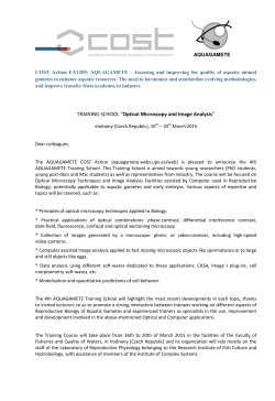
© Copyright 2026