ABC
docz
Explore
Log in
Create new account
Download
Report
No category
Span 400 VX Användarinstruktion
DI W ? HAT IS
Standard Features
Book 1 - Destination Imagination
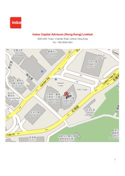
Indus Capital Advisors (Hong Kong) Limited Tel: + 852-3652-030
Mono Tower ALUMINIUM TOWER SYSTEM
4 Annual Region II FSAWWA Model Water Tower Competition
Patient Leadership Programme â May 15/ Apr 16
Spaghetti Towers Aim:
Parking Permit - WordPress.com
Section 5.7: The Cosine Law
© Copyright 2026
About abcdocz
DMCA / GDPR
Report