
Publisher version
Downloaded from orbit.dtu.dk on: Feb 15, 2016
Application of product modelling - seen from a work preparation viewpoint
Hvam, Lars; Vesterager, Johan
Publication date:
1996
Document Version
Publisher's PDF, also known as Version of record
Link to publication
Citation (APA):
Hvam, L., & Vesterager, J. (1996). Application of product modelling - seen from a work preparation viewpoint.
Technical University of Denmark. (IPV Publication; No. 96.13-A).
General rights
Copyright and moral rights for the publications made accessible in the public portal are retained by the authors and/or other copyright owners
and it is a condition of accessing publications that users recognise and abide by the legal requirements associated with these rights.
• Users may download and print one copy of any publication from the public portal for the purpose of private study or research.
• You may not further distribute the material or use it for any profit-making activity or commercial gain
• You may freely distribute the URL identifying the publication in the public portal ?
If you believe that this document breaches copyright please contact us providing details, and we will remove access to the work immediately
and investigate your claim.
FOREWORD
This thesis is the result of a Ph.D. project performed at the Production Engineering Department at the Technical University of Denmark under the supervision of Dr. Johan
Vesterager. The project has been funded by the Danish Technical Research Council as part
of the Inte-grated Production Systems (IPS) research project.
In addition to working at the Production Engineering Department, I have also had more
than a year's collaboration with Alfa Laval Separation A/S in Søborg, where the empirical
part of the project has been carried out. I should therefore particularly like to thank their
chief pro-duction engineer, Poul Erik Nielsen, who has followed the progress of this Ph.D.
project and contributed to it with essential information and many interesting discussions. I
should also like to thank the other members of the staff of Alfa Laval Separation who have
been invol-ved in this project for showing their interest in what was going on, and for
offering informa-tion and comments.
I should also like to thank Johan Vesterager for his advice and for many exciting
discussions, and my fellow Ph.D. students Geir Arngrimsson of the Production Engineering
Department and Niels Henrik Mortensen of the Institute of Engineering Design, who have
been heavily involved in the empirical work and have contributed much useful knowledge,
and with whom I have had many exciting discussions about object-oriented modeling and
the con-struction of design support systems respectively. In addition I would like to thank
Lars Carstensen, a Master's thesis student at our department, for having performed the
arduous task of programming the model described in this thesis.
Finally I would like to thank the staff of the Production Engineering Department, and in
particular Torsten Höök and Christian Glyrskov, who have helped me with illustrations and
with the task of producing the thesis.
Lyngby, August 1994.
This version of the Ph.D. thesis is a translation to English of the original Danish version
published in August 1994.
Lyngby, June 1996.
Lars Hvam
i
ABSTRACT
Manufacturing companies spends an increasing amount of the total work resources in the
manufacturing planning system with the activities of e.g. specifying products and methods,
scheduling, procurement etc. By this the potential for obtaining increased productivity
moves from the direct costs in the production to the indirect costs in the manufacturing
planning system.
This Ph.D.-project consider information technology (IT) to be an important means for
obtai-ning increased productivity and efficiency in these functions. The project focuses on
the use of IT to support the activities of specifying products and methods, as only a minor
part of the engineering work in these functions in the planning system until now has been
supported with IT. The aim is to develop methods for analysing which activities to support
with IT, and in relation to this, define context and structure of the IT-systems to support the
specifi-cation work.
The theoretical fundament of the project include four elements. The first element (work
pre-paration) consider methods for analysing and preparing the direct work in the
production, pointing to an analogy between analysing the direct work in the production and
the work in the planning systems. The other element covers general techniques for
analysing and mode-ling knowledge and information, with special focus on object oriented
modeling.
The third element covers four different examples of product models. The product models
are viewed as reference models for modeling knowledge and information used for
specifying products and methods. The last element attach to the use of the task concept
viewed as a means for expressing the demands to a given system in the company. In this
case, systems for specifying products and methods.
Based on the referred theory, the project provides a line of procedure for developing systems to support the specification activities in the company using product models. The first
phase in the procedure contain an analysis of the task of the system (called the product and
methods specification task) leading to a definition of the context and structure of the system
in the specific company. The following phases are based on the use of object oriented
mode-ling and follow in outline the object oriented project life cycle.
The empirical work in the project, carried out at Alfa Laval Separation A/S, covers all the
phases in the line of procedure from analysing the task of the system, over building a
model, and to the final programming of an application. It has been stressed out to carry out
all the phases in the outline of procedure in the empirical work, one of the reasons being to
prove that it is possible, with a reasonable consumption of resources, to build an application
to support a part of the specification work in the company.
ii
CONTENTSI
1. Introduction ......................................................................................................................... 1
1.1 Background ................................................................................................................... 1
1.2 The Procedure followed in the Project .......................................................................... 3
1.3 The Structure of the Report ........................................................................................... 7
2. Theoretical foundations....................................................................................................... 9
2.1 Work study .................................................................................................................... 9
2.1.1 Information technology in technical planning and control .................................. 11
2.1.2 An analogy to traditional analysis and the rationalisation of production work. .. 13
2.1.3 Summary .............................................................................................................. 19
2.2 Modeling of knowledge and information .................................................................... 21
2.2.1 Data and knowledge representation forms ........................................................... 22
2.2.2 Three-schema architecture and the project life cycle ........................................... 25
2.2.2.1 Three-schema architecture ............................................................................ 25
2.2.2.2 The ICAM project life cycle .........................................................................27
2.2.2.3 The object-oriented project life cycle ...........................................................29
2.2.3 IDEF modeling .....................................................................................................31
2.2.3.1 Function modeling (IDEF0) .......................................................................... 31
2.2.3.2 Information modeling (IDEF1): .................................................................... 34
2.2.4 Object-oriented modeling.....................................................................................38
2.2.4.1 Object-oriented analysis ................................................................................41
2.2.4.2 Identification and characterisation of objects (OOA) ...................................42
2.2.4.3 Object-oriented design ..................................................................................46
iii
2.2.4.4 Object-oriented programming ....................................................................... 47
2.2.5 The CIM/OSA reference model ........................................................................... 49
2.2.6 The STEP standard............................................................................................... 53
2.2.7 Summary .............................................................................................................. 59
2.3 Concurrent engineering and product modeling........................................................... 61
2.3.1 Concurrent engineering ........................................................................................ 61
2.3.2 The concept of features ........................................................................................ 65
2.3.3 Product modeling ................................................................................................. 70
2.3.3.1 The Fraunhofer Institute in Berlin ................................................................ 71
2.3.3.2 The University of Erlangen-Nürnberg .......................................................... 75
2.3.3.3 Dataforeningen in Sweden ............................................................................ 79
2.3.3.4 The Institute of Engineering Design, DTU (The chromosome model) ........ 82
2.3.4 Summary .............................................................................................................. 85
2.4 The task concept.......................................................................................................... 88
2.4.1 Background .......................................................................................................... 88
2.4.2 The production task.............................................................................................. 90
2.4.3 The manufacturing task in the UPS project ......................................................... 94
2.4.4 The production planning and control task............................................................ 97
2.4.5 The development task ........................................................................................ 100
2.4.6 Summary of the task concept ............................................................................. 104
2.5 Problem formulation ................................................................................................. 106
2.5.1 Assumptions ....................................................................................................... 107
2.5.2 Limitations of the project ................................................................................... 107
2.5.3 Summary ............................................................................................................ 108
iv
3. Hypothesis ....................................................................................................................... 109
3.1 Introduction ............................................................................................................... 109
3.2 The procedure............................................................................................................ 109
3.2.1 A/S Reoler an example....................................................................................... 111
3.3 The product and method specification task ............................................................... 113
3.3.1 Use of the task concept ...................................................................................... 114
3.3.2 The content of the task concept .......................................................................... 116
3.3.3 Purposes view and contexts ............................................................................... 126
3.4 Building up an OOA model ...................................................................................... 127
3.5 Design, programming, implementation and maintenance ........................................ 133
3.6 Summary ................................................................................................................... 134
4. Empirical results.............................................................................................................. 136
4.1 Alfa Laval Separation A/S ........................................................................................ 136
4.2 The procedure used in the project ............................................................................. 138
4.3 The product and method specification task ............................................................... 140
4.3.1 The purpose, view and context of the model ......................................................... 144
4.4 Building up the OOA model ..................................................................................... 145
4.4.1 Presentation of the domain ................................................................................. 145
4.4.2 Identification of features .................................................................................... 149
4.4.3 The product model ............................................................................................. 153
4.4.4 The production model ........................................................................................ 158
4.5 Constructing the OOD model.................................................................................... 163
4.6 Programming the model ............................................................................................ 167
4.7 Presentation of the system......................................................................................... 171
v
4.8 Summary of empirical work ..................................................................................... 177
4.8.1 The product and method specification task........................................................ 177
4.8.2 The procedure .................................................................................................... 178
4.8.3 Effects of using product and product related models ......................................... 179
4.8.4 The perspectives for Alfa Laval Separation ....................................................... 180
5. Conclusion ...................................................................................................................... 182
5.1 Evaluation of the hypothesis ..................................................................................... 182
5.2 Putting the project into perspective ........................................................................... 185
Literature: ............................................................................................................................ 189
Appendix 1. OOA-model for manufacturing of bookcases ................................................ 199
Appendix 2. Formulae for calculation of geometry-data etc.
for object 19 in the product model............................................................... 206
Appendix 3 Formulae for calculation of time consumption
at object 110 in the production model .............................................................. 208
vi
1. INTRODUCTION
1.1 BACKGROUND
As a result of the increased use of information technology (IT),marked changes are currently
taking place in the area of technical planning and control (product planning, methods engineering, quality control, logistics and production planning) in companies involved in production activities.
At the same time, these companies use a continually increasing proportion of their resources
for technical administration, so that the potential for achieving increased productivity is
changing from primarily involving physical production to also involving production and
development tasks associated with technical planning and control.
As an example I may mention the ABB concern, which has just initiated a large scale project
entitled "production in half the time", which focuses on companies' overall order flow, including the production preparation activities involved in planning and control. As part of this
project, an investigation of the flow of orders in a number of companies within the concern
has been carried out. The investigation showed amongst other things that work was being
performed on a given order during about 5% of the overall throughput time. For 95% of the
time the order was sitting untouched.
In connection with the ICAM project in USA [Vesterager, 124], this is described by saying
that the production engineer's point of view changes from "the manufacturing of the product" to "the manufacturing of the manufacturing system". Thus planning and control tasks
are to an increasing extent being changed so that they also include the development and
maintenance of systems for performing the daily methods engineering tasks associated with
technical planning and control.
Important targets are to achieve a faster and more certain throughput of orders, and increased productivity in dealing with orders, at the same time as the company obtains more freedom with respect to how orders are to be passed through the system. This is achieved, for
example, by not specifying several products/components until the order of which they are
part has to be dealt with, and then using a computer supported design and production engineering system based, for example, on object-oriented modeling of products and process
plans.
The key technology for the development of functions for technical planning and control is
information technology (IT). Methods (such as IDEF methods) are currently available for
describing functions and pieces of information. Thus there is a "language" for modeling the
structures of tasks and the relationships between pieces of information, in connection with,
for example, order production (design and production engineering). On the other hand there
are as yet no operational procedures and methods for determining the degree of computer
1
support which has to be selected for the individual functions. An analogy can be made with
the mechanisation and automation which have been introduced in the production process,
where there are a number of analysis models available for describing the processes which are
carried out (for example, MTM studies), together with methods or general rules for how to
choose the degree of mechanisation.
Thus a central question is how the possibilities offered by information technology should be
incorporated when building up the routines used in technical planning and control. At present, there is no set of concepts or methods available to help companies to decide the extent
to which the individual functions are to be integrated, or the degree of computer support or
computer-based automation.
In this project I have chosen to focus on the specification activities which take place in the
company. In Figure 1 below, the individual functions within the company are shown divided
up into two different streams, where the horizontal stream shows activities related to the
control of how an order passes through the system (the logistic flow), while the vertical
stream (the specification flow) shows activities related to how the product is created specification and manufacturing.
Product
Productspecification
Methodspecification
Order
Receipt
of order
Planning
Purchasing
Initiation
Production
Monitoring
Qualitycontrol
Figure 1. Logistic flow and specification flow within the company
[Hirsch, 52].
The logistic activities in the horizontal stream can to a considerable extent be supported by
general applications (standard or framework systems) such as MAPICS, COPICS or SAP,
2
as the work routines supported by these applications are similar in many companies involved
in production.
The activities in the vertical stream, involving specification of the product and its production, are associated with the individual company's products and production apparatus, and
can thus only be supported by general applications, such as CAD or programming equipment
for CNC machines, to a modest extent. For example, CAD systems primarily support the task
of documentation, but not the content of the actual engineering tasks. 1
To support the tasks of specifying products and production methods, it is necessary to build
up an application based on an analysis of the individual company's products and production
apparatus. An essential tool in this connection is the use of product and product-related models (product modeling), which will be described in more detail in the next chapter.
This project has, as previously mentioned, focused exclusively on activities in the vertical
stream, i.e. specification of the product and its manufacturing process. This is the area in
which production companies use a continually increasing portion of their resources, while at
the same time a considerable international research effort is going into the creation of theories and methods for supporting these activities.
In the literature, examples can be found of product and product-related models (see
Section 2.3.3), and of theories of which knowledge and information such models
should include, whereas I have not been able to find any theory for how to deduce
which design and methods engineering activities in a given company should be supported by product and product-related models.
1.2 THE PROCEDURE FOLLOWED IN THE PROJECT
The procedure followed during the project can be described partly in terms of an interaction
between theory and practice, and partly as a combination of analysis and synthesis. In general terms, the scientific method can be described as critical rationalism, where an attempt is
made to develop existing perceptions, in form of models and methods, further by making use
of literature studies, investigations of logical structure, empirical work and so on.
Figure 2 below shows the elements of the scientific procedures followed. Two different procedures are illustrated. In the first of these, the starting point is a problem, and an analysis
phase is used in an attempt to obtain understanding of and insight into the problem domain
1
In this thesis, the terms "knowledge- and information-oriented tasks" are used as general terms for the
activities which are related to the storage and retrieval of information (information-oriented tasks) and to
the generation of new information (knowledge-oriented tasks). Specification-oriented tasks are in this
context knowledge- and information-oriented tasks in the company's specification flow, and by
engineering tasks I primarily mean the knowledge part of the knowledge- and information-oriented tasks
in the company's specification flow.
3
by exposing structures and relationships etc. In a subsequent synthesis phase, models and
methods for solving the problem are formulated, and the consequences of the proposed solution are evaluated.
Scientific work paradigms
Problem base
R
E
S
E
A
R
C
H
Theory base
SYNTHESIS
ANALYSIS
Building up structures
Internal consistens, etc .
Revealing structures,
causality, empirical ,
results etc.
Diagnosis
Model
ANALYSIS
SYNTHESIS
External consistency,
usability, etc.
Generation of solutions,
Evaluation of consequenses
D
E
V
E
L
O
P
M
E
N
T
New scientific
perception
New scientific
perception
KNOWLEDGE TRANSFER
Adaptation of methods,
implementation, etc.
Practical
results
Figure 2. A scientific working procedure [Jørgensen, 74].
4
In the other procedure, the starting point is the existing theory, and a synthesis phase is used
to set up models and methods which explain a given phenomenon (problem), after which
these models and methods are tested in an analysis phase, in which the proposed theory's
consistency and usability is evaluated.
In the current project, a combination of these two procedures has been used, where I sometimes start from a problem (to set up models and methods for supporting the tasks of design
and methods engineering), and sometimes start from relevant theories in this area (for task
preparation, modeling of knowledge and information, product modeling and the task
concept).
In the figure, the scientific task is also divided into research and development, where the
latter includes adaptation and implementation of research results, so that they can be used
operationally in a particular company. In this Ph.D. project, emphasis has been placed on
making the proposed models and methods "finished", so that they can be used in an operational manner within individual companies. Another important aspect of the project has been
the use of Linstone's theory of the significance of perspectives for the solution chosen
[Linstone, 87]. Linstone states that the perspectives which are adopted during analysis of a
problem determine the validity of the final solution. The optimum solution to a problem seen
from one point of view can be unsuitable seen from other points of view.
Linstone formulates three main groups of perspectives in connection with analysis of systems: a technological perspective, an organisational perspective and a perspective oriented
toward individuals. This project consider the group of technological perspectives, and when
formulating an hypothesis, a number of these perspectives are used as the basis for the hypothesis, while other perspectives are more or less excluded, in order to limit the extent of the
project. Efforts have been made to ensure that it is made quite clear which perspectives are
included and which are excluded.
Figure 3 below shows how the project has proceeded. The procedure is based, as mentioned
above, on a combination of the procedures shown in Figure 2, starting partly from a problem
and partly from a study of the literature in the area concerned. The empirical work has been
used to contribute both to the analysis and evaluation of the chosen hypothesis, and to a synthesis in which the hypothesis was reformulated and extended.
5
Formulation of
problem
Study of
literature
Limitation of project and formulation of initial hypothesis
Correction and
extension of
hypothesis
Empirical work
Study of literature
Final hypothesis
Writing report
Figure 3. The working procedure followed in the project.
The study of the literature has continued throughout the project up to the formulation of the
final hypothesis. The main effort in the study of the literature has partly been expended during the early phases of the project, where the limits to the project were set and the initial
hypothesis was formulated, and partly during the empirical work, during which the hypothesis was continually reformulated and extended, during the three first activities, there was
some overlap and iteration between formulating the problem, studying the literature and
formulating the initial hypothesis.
6
1.3 THE STRUCTURE OF THE REPORT
This report is divided into four main parts (see Figure 4), where the first part deals with the
theoretical basis for the project, its final delimitation, and the assumptions on which the project is based. The second part contains a formulation of the proposed hypothesis, while the
third part contains a description of the empirical work which has been carried out at Alfa
Laval Separation A/S. The final part contains an evaluation of the proposed hypothesis and
sets the results of the project into perspective.
Teoretical basis
Work preperation
IT-modelling
Product modelling
Task concept
Hypothesis
Procedure
The product and method
specifikation task
Emprical results
Specification of task and
construction of model at
Alfa Laval Separation A/S
Conclusion
Evaluation of the proposed
hypothetis and setting the
project results into perspective
Figure 4. The structure of the report.
The theoretical basis of the project is made up of four different elements. The first element
(work preparation) contains a description of methods for determining the optimum work
preparation (or support) for the technical planning and control functions within a company,
and an work analogy is made with methods for analysing and preparing for the actual production tasks.
7
The second element consists of a short presentation of basic concepts and techniques for the
modeling of knowledge and information, with special emphasis on the use of object-oriented
modeling. In addition, there is a short description of the CIM/OSA reference model and the
STEP-standard as these are expected to contribute to coming standards in this area.
The third element deals with product modeling, which is set in relation to concurrent engineering and the feature concept. Reference is made to four different examples of product and
product-related models, which can be considered as reference systems which determine the
general content and the general structure of product and product-related models.
Finally, in the fourth element, the task concept is presented and its application in Danish industry in three large Danish projects, Development of Production Systems (UPS), Company-specific Production Control (ViPS) and Focus on Development Ability (UNIC), is discussed. The theoretical discussion finishes with a definition and delimitation of the project
and the assumptions on which it is based.
The theoretical basis of the project forms the foundation for the hypothesis which has been
formed, which involves an overall procedure for development of systems, which can support
activities in the company's specification flow. The first part of the procedure involves an analysis of the system's task, expressed in terms of the product and method specification task,
which - seen from a task preparation perspective - contributes to the definition of the future
structure of the company's specification flow (here primarily design and methods engineering).
Following this, the procedure consists of a number of phases, based on the use of objectoriented modeling, which lead to the construction of the IT systems which are to support
activities within the specific company. Analysis of the product and method specification task
forms the foundation for the task of building up the IT systems, as the analysis of which activities are to be supported determines the content and structure of the IT systems, which are
to be built up based on the content and structure of the general reference models for product
and product-related models.
The project's empirical work has been carried out at Alfa Laval Separation A/S in Søborg.
The empirical work has made it possible to perform an analysis of which design and methods
engineering activities it would be interesting to support by IT (the product and method specification task), and to build up an application which contains knowledge and information for
the support of design and methods engineering for one of the components which make up
part of the company's product program (decanters).
Emphasis has been placed on carrying out the whole process (formulated in the procedure),
from the determination of the content and structure of the system (by use of the product and
method specification task) through to the programming of an application.
Finally, the proposed hypothesis is evaluated in relation to the empirical work carried out,
and the hypothesis' validity is judged from the point of view of the perspectives which are
used in the project. In addition, the results of the project are put into in perspective, and the
hypothesis is related to other points of view, such as those of organisation and integration.
8
2. THEORETICAL FOUNDATIONS
2.1 WORK STUDY
In this section I will present the general philosophy and the point of view used in this project
with respect to the development of systems for technical planning and control. A technical
planning and control system, as defined in [Vestager, 125] is shown in Figure 5 below.
Technical planning and control involves the planning and control of the product, method and
quality, together with logistics and production planning and control.
Produc t
Design
Handling
Proc ess
Quality
Methods
Plant
Materials
Capacity
Innovation
Specific ation
Introduction
Indirect
monitoring
Direct
monitoring
Produc t
planning
and c ontrol
Method
planning
and control
Quality
planning
and control
Logistics
Production
planning and control
PRODUCTION
Figure 5. Technical planning and control in the company.
Product planning and control involves all activities concerned with planning, development
and specification of the company's products. Method planning and control involves development of the company's production apparatus, together with specification of the running activities associated with production (routing, operational advice, cnc coding, tool design etc.).
Quality planning and control is here shown as an independent activity, but can in fact be considered as a parameter which affects all activities within the company. Logistics is here used
in the sense of control of the purchase of materials and subcontractor services, together with
plant planning, while production planning and control involves the planning of the individual
production activities, i.e. the planning of materials and operations in relation to the available
capacity.
9
The technical planning and control system has arisen as a result of the extensive division of
labour and mechanisation which has been introduced in production. An essential prerequisite
for the improvements in productivity, which have as time goes by been achieved in production since the initial introduction of the division of labour at the end of the previous century,
is the development of methods for analysing and preparing the task of production, together
with the exploitation of mechanical technology to support the individual work operations.
The various functions in a company which correspond to the various phases in the product
life cycle are shown in Figure 6 below. The figure only includes those phases which are related to activities in a manufacturing company, so that for example phases such as the use and
the disposal of the product are not included in this context. The individual activities associated with the specification and manufacture of the product are shown as consisting of three
levels.
Strategic planning and coordination
Delivery
Production
Production planning og control
Quality control
Purchasing
Method
engineering
Design
Sa les
(Contra cting for
ord ers)
Preperation/innovation
Product fabrication ( operation level )
Figure 6. The company's functions, showing the operational, preparation
and coordinating levels.
The operational level describes the actual work of sales, specification, purchasing, planning
and manufacturing of products. The preparation level indicates the development of systems
which can support activities on the operational level, for example development of the production system by changing the layout or the production equipment, or the building up of
product and product-related models to support specification activities in design or methods
engineering.
In relation to the functions of technical planning and control shown in Figure 5, it should be
noted that the activities involved in method planning and control are divided into those activities which prepare (develop) the production system, and those which, on an operational
10
level, specify the activities (operations) to be performed during production. The strategic
level involves the coordination of the individual subsystems, and sets up the ground rules for
building up the systems in accordance with the company's overall strategy.
The preparation level in Figure 6 indicates the need to develop systems and to support functions in the company's technical planning and control, using IT, in the same way as production has up till now been developed and supported by the use of mechanical technology.
In the ICAM project, this fact has, as previously mentioned, been formulated by saying that
the focus of attention has changed from being "Manufacturing of the product" to being
"Manufacture of the manufacturing system", which means that systems for performing the
daily operational routines concerned with the specification and manufacturing of products
have to be developed and implemented.
2.1.1 INFORMATION TECHNOLOGY IN TECHNICAL
PLANNING AND CONTROL
In connection with the development of functions within the system for technical planning
and control, information technology (IT) is an important tool for achieving improvements in
the efficiency of these functions. IT is developing rapidly. The price/performance ratio is
dropping rapidly, and new technical possibilities (such as graphical communication using
images and films) are appearing, which means that the potential area of application of IT is
continually being expanded. It is especially developments in hardware which are going
rapid-ly, but there is also a continual development in methods for efficient development of
soft-ware, such as object-oriented systems and CASE tools [Kirkby and Kjærulf, 78].
Information technology is being used to an increasing extent in the technical planning and
control system, a fact which is confirmed by several investigations into companies' use of IT;
[Arthur Andersen, 13], [Foss Michelsen, 44], [Price Waterhouse/IKO, 101] and [Danish
Industrial Employers' Association, 65]. In these investigations, the following trends in the
use of IT in Danish manufacturing companies are indicated:
• The use of IT is having increasing influence on manufacturing companies' productivity
and competitiveness.
• Company management is to an increasing extent involved in the use of IT.
• Companies are investing more and more money in IT. In the period 1985-1991, annual
costs for edp rose by 120% measured in fixed prices.
• Responsibility for the development and maintenance of computer systems is being decentralised, and is to an increasing extent being taken over by the users.
• External networks between companies (EDI techniques) are being used to an increasing
extent.
11
The conclusions indicate that the use of IT is of increasing significance for the competitiveness of manufacturing companies. Company management is becoming more involved in the
exploitation of IT, and more and more people consider the exploitation of IT to be a competitive factor on an equal footing with product development and rationalisation of production. More money is being invested in IT, and most companies experience pressure from
suppliers and customers to use IT for external communication.
At the same time it is stated that many manufacturing companies have difficulty in understanding the tasks of technical administration, and therefore rationalise these tasks by using
IT. [Danish Industrial Employers' Association, 65] formulates this as follows:
"A central question in this connection is how a company can take hold of the
administrative tasks, so that they appear in such a transparent manner that the
company can find a basis for managing the administrative functions and making
them more efficient".
In other words, there is an increased interest in using IT in manufacturing companies, and at
the same time a realisation that there is a lack of methods and procedures for analysing and
modeling those knowledge and information tasks within the company, which have to be supported and made more efficient by IT.
In 1992, [Christensen & Clausen, 25] performed an investigation of manufacturing companies' use of IT in technical functions. The investigation, which covered 100 companies in the
mechanical and electronic engineering industries, came to the conclusion that most companies use computers for design and methods engineering. The systems used are general ones,
such as CAD, spreadsheets and database systems, while more advanced applications with a
marked knowledge content, for example for processes selection, are only used to a small
extent.
In connection with the use of general knowledge-based systems for supporting design and
methods engineering tasks, [Alting & Zhang, 2] have performed an investigation into the use
of process selection systems (Computer Aided Process Planning, CAPP, systems). In this
investigation, which considered 150 CAPP systems, it was stated:
"In spite of the fact that tremendous efforts have been made in developing CAPP
systems, the benefits of CAPP in the real industrial environment are still to be
seen".
Many resources had been invested in the development of general process selection systems,
but they had not (in 1989) achieved any notable degree of acceptance in industry. The investigation concluded that one reason for the failure to apply them could be failure to achieve an
overall view of the systems on offer, together with a lack of knowledge of which criteria
should be used for selection and evaluation of a CAPP system.
Another aspect could be that the choice of processes is related to the individual company's
product and production system, so that it can be difficult to model all relevant points of view
12
for process selection in a general system which can be used in several companies, without
this system being on a general level and only able to cover a small part of the company's
product range.
To sum up, it must be stressed, as mentioned in Section 1.1, that the activities associated
with the technical planning and control system consume a larger and larger portion of the
company's manpower resources. Of these activities, it is primarily the activities in the company's logistic flow (Figure 1) which have until now been supported by generic applications
(such as MRP systems) which can contribute to the performance of some of the working
routines in this area, while the activities in the company's specification flow, which include
the design and methods engineering functions, have only to a small extent been supported by
tools such as CAD and programming equipment, which does not directly help to perform
working routines (the real engineering tasks), but merely support tasks such as drawing and
programming.
There is considerable potential in supporting the engineering activities in the company's specification flow with IT, as companies use an increasing portion of their manpower resources
for these activities, and because this type of activity has until now only been supported to a
modest extent. Support of such activities is, as previously mentioned, associated with the use
of product and product-related models which contain engineering knowledge and information about the product and, for example, its manufacturing process.
Product and product-related models contain knowledge and information about the individual
company's specific products and production system, and must thus be put together individually for each particular company, possibly by the use of general (purchased) software components (Section 2.2.5-2.2.7). In this connection it is necessary to determine which activities
have to be supported, and thus which knowledge and information the model must include.
2.1.2 AN ANALOGY TO TRADITIONAL ANALYSIS AND THE
RATIONALISATION OF PRODUCTION WORK.
In this section I shall consider some of the techniques which are used for analysing and describing the work which are performed during production, and will try to draw an analogy
between traditional work analysis in production and analysis of the knowledge and information work which are performed in the technical planning and control system.
In Figure 7 below, all work is considered as being made up of three elements, an intellectual
element, a sensory element, and a motor element [Vestager, 123, p.14]. The motor element
includes the directly physical work elements, such as grasping or lifting. The sensory
element includes tasks such as the registration and identification of items, while the
intellectual ele-ment involves the processing of data (sensory impressions) and the
preparation of the opera-tion (knowledge and information work).
13
Intellectual
work
Sensory
work
Motor
work
Figure 7. The elements of work [Vesterager, 123, p.14].
In connection with the mechanisation of production work, it is primarily the physical work
elements (the heavy mechanical work) which is supported by mechanical technology. This is
typically the case for mechanisation carried out in companies involved in one-of-a-kind and
batch production, where machines perform the heavy mechanical tasks, while the sensory
and intellectual work are still performed by the operator. The use of CNC machines and sensors is in this context an example of how IT is used to support the sensory and intellectual
production work. Another example is in mass production, where all work elements are performed automatically, with the sensory and intellectual work elements to a great extent mechanically embedded in the construction of the production system (stiff automation).
In mass production, a considerable amount of preparation for the work to be done is performed, as the elements of this work are analysed and to a considerable extent automated or
mechanised. Mass production involves preparation (and automation) to a greater extent than
for example batch production.
Work preparation is here defined in a general manner as the preparatory work which are performed before the actual operational work. Thus the preparatory work include analysis of
which auxiliary means (machines and tools) it can pay to purchase or develop for carrying
out the operational work. The degree of support (here the degree of mechanisation) is in what
follows generally denoted the degree of preparation.
In connection with the mechanisation of production, the optimal degree of preparation is
determined from an analysis of the nature of the work and the frequency with which it is
carried out. By analysis of the nature of the task, we mean analysis and description of the
elements of the task and determination of the relationship between the task (work element)
and the machines/tools which can support this work.
When the mechanical operations in production are rationalised, methods are available for
analysing and specifying the work, as the individual operations are broken down into welldefined sub-operations falling in the following four categories:
perform process
inspect
14
transport
store
The individual sub-operations can then be further subdivided, for example following the
principles of MTM (Methods Time Measurement) analysis, which is used to classify manual
work operations, where the individual sub-operations are broken down into so-called basic
elements, such as stretch, move, twist, press, grasp, adapt, release and loosen.
The operations which are analysed can either be purely manual or be performed together
with a machine. In the latter case, a so-called man-machine analysis is performed, describing
the sub-operations carried out respectively by the employee and the machine and their relative order.
The aim of analysing work operations in this way is partly to determine the time needed for
the operation, and partly to minimise this time by optimising the sub-operations which are
performed. Optimisation of sub-operations can be achieved in several ways. Small changes
can be made to the product, so that for example it becomes easier to assemble. The task can
be organised in a different way by changing the order or content of the individual suboperations. Or finally the operation can be improved by changing the equipment (machine,
tool or fixture) which is used. In this last case, it is the detailed analysis of the operation
which forms the basis for mechanisation of basic elements which were previously performed
manually.
In connection with a production sequence, there is often a combination of manual, mechanical and automatic operations. Figure 8 below shows how various operations in a sequence
can be performed with various degrees of mechanisation. An example of this is in assembly
lines, where in many companies there is a mixture of manual, mehanical and automatic work.
Degree of mechanisation
Automatic
Mechanical
Manual
Activities
Figure 8. The working procedure with varying degrees of
mechanisation.
"Manual operations" refers to a procedure in which the operator, possibly with limited mechanical aids, himself controls and performs the process. "Mechanical operations" refers to a
15
procedure in which the motor/mechanical work are primarily performed by a machine, while
the operator still controls the sequence of operations (possibly in an interaction with the machine), while an "automatic operation" is performed without the operator directly being
involved, as the operator is here typically only responsible for monitoring and control of the
process.
In the context of the analysis of work in a company's technical planning and control, one can
in a similar way talk of a varying degree of IT support. An operation (a work procedure) can
be performed without using IT (corresponding to a manual operation). The operation can be
performed in an interaction with IT, where IT supports the function (corresponding to a
mechanised operation), or it can be performed automatically solely by the use of IT
(corresponding to an automated operation).
The relationship between the task and the tool or machine is known as correspondence,
where a high degree of correspondence means that the tool or machine can support the task
to be performed to a considerable extent.
In connection with correspondence between task and tool, the term tool homogenisation is
used to denote the development of tools, such as universal grasping tools, finishing centers
and so on, which can support many different tasks. Correspondingly, the term task homogenisation means that the tasks which are to be performed on a given machine or tool have
been made uniform seen from a tool point of view, where we here consider a tool as a general aid, which could be a machine, a tool, a fixture and so on. Task homogenisation from a
tool point of view is often used in connection with the classification of items (for example
using group technology) to be processed, so that these items are uniform from the point of
view of machining, handling, assembly or whatever. The various "Design for X" methods
correspondingly have as their aim the design of products which are uniform with respect to
machining, handling, assembly and so on. Conversely, a "manufacturing for design" review
could have tool homogenisation as its aim.
In the system for technical planning and control, it is, as previously mentioned, primarily
knowledge and information tasks which are performed. By supporting technical planning and
control activities with IT, for example by building up systems for specification of the product
and its manufacturing procedure, one can in a corresponding manner talk of making the
products specification-uniform (design-uniform, methods engineering-uniform, etc.)
[Vesterager, 123].
The criterion for when it is optimal to support one or more sub-operations by using machines is that it must be possible to describe the operation unambiguously (it must be analysable), the operation must be performed in the same way every time, which implies that the
items which are to be processed in the operation must be uniform from a tool point of view.
And finally, in order that any investment in machines or equipment should be profitable, it is
necessary that the operation be performed sufficiently often.
16
Tota l
p rod uc tion
c osts
Tota l avera ge
c osts pe r prod uc t
Numb er of
p ro duc ts
of typ e x
Numb er of
prod uc ts
of typ e x
Figure 9. Cost per item for various degrees of mechanisation.
The above criteria are derived from a general economical criterion, which is to achieve the
lowest possible cost per item (total average costs). Figure 9 shows costs per item for varying
degrees of mechanisation, where the total production costs are divided up into fixed and
variable costs. By manufacturing products in large volumes, a high degree of methods
engineering and mechanisation can be introduced, which minimises the variable costs per
unit and thus the total average costs per item.
The interesting thing about making products X-uniform by a combination of task and tool
homogenisation is that in this way one achieves a higher volume of uniform operations, so
that one moves further down the total costs per item curve. This fact is generally known in
connection with the design of production systems, but corresponding considerations will also
be relevant to the design of systems for supporting the company's specification tasks.
An important tool for grouping product components according to particular manufacturing
methods is the use of group technology [Burbidge, 19], [Sant, 110]. To group items,
classification systems are used which group components according to various criteria, for
example the grouping of axles on the basis of criteria for performing turning operations, such
as geometry, materials and surfaces. There are a large number of group technology
classification systems and various methods for grouping items.
17
S
S2
S1 S3
D1 D2 D3
Df
Dh
H - number
v
Fb
Fd
Cl.nr.
DI
D2
D3
Df
Dh
S
SI
S2
S3
Fd
Fb
H
Number
V°
1
01102-3900
80
67,7
27
-
56
12
2
-
-
-
-
8,4
2
-
40
2
01102-3900
80
67,7
21
-
56
10
2
-
-
-
-
8,4
2
30
3
01102-3910
80
67,7
30
64
56
17
-
4
-
-
8,4
2
20
80
4
01102-3910
100
87
27
82
78
24
-
5
-
-
8,4
4
30
25
5
01102-3910
80
67,7
24
56
56
17
-
4
-
-
8,4
2
15
45
6
01132-3910
100
87,9
27
-
78
18
3
-
-
5
16
8,4
4
-
100
7
01132-3910
80
67,7
27
-
56
16
2
-
-
5
15
8,4
2
-
70
8
01132-3900
80
67,7
21
-
56
15
2
-
-
5
15
8,4
2
-
90
9
01102-3900
100
87,9
27
-
78
13
3
-
-
-
-
8,4
4
-
70
10
00100-2900
67,7
-
21
-
-
12
-
-
-
-
-
-
-
-
80
11
00100-2900
67,7
-
27
-
-
12
-
-
-
-
-
-
-
-
75
12
00102-3900
80
67,7
27
-
56
10
2
-
-
-
-
8,4
2
-
50
13
01132-3900
80
67,7
27
-
56
15
2
-
-
5
15
8,4
2
-
85
14
01102-3900
80
67,7
30
64
56
17
-
4
-
-
8,4
2
20
60
15
01132-3900
100
88
30
82
78
24
-
5
-
-
8,4
4
30
75
16
04102-3900
100
88
27
-
78
16
3
5
3
-
-
8,4
4
-
90
17
01100-3900
87,5
75
27
-
-
10
2
-
-
-
-
-
-
-
Run
Drawing
length
nr.
20
Figure 10. A complex component with 17 instances [Sant, 110, p.206].
Figure 10 above shows an example of a so-called complex component, which describes a
group of components with uniform manufacturing properties.
Originally, group technology was associated with the grouping of product components
according to manufacturing method, so the word "technology" in group technology must be
understood in the sense of manufacturing technology. [Sant, 110] draws an analogy between
18
manufacturing processes and decision processes, where group technology for a decision
maker means that he has to relate uniform tasks and work out a solution for the group of
tasks, rather than specific solutions for each individual task.
[Sant, 110, p.37] continues:
"The original idea of group technology about simultaneous processing of uniform products is extended in two areas: Products have been replaced by the
more general concept of tasks, and the condition of simultaneity in the groupwise processing has been eliminated."
In other words, the idea is presented that group technology should be used for knowledge
and information tasks (decision processes). Continuing from there, the conclusion is drawn
that with the existing classification systems (1976), there are limited possibilities for grouping uniform tasks it is only possible to group tasks in the industrial organisation which are
closely associated with a product's origin.
Thus group technology can be considered as a method for grouping similar tasks, so as to
obtain an increased frequency, which enables us to perform methods engineering to a greater
extent, and thus to move further down the cost per item curve of Figure 9. The philosophy of
group technology also been seen the use of product modeling, where knowledge and
information about similar products are collected in a model which forms the basis for programming an application which can support specification tasks.
Thus in this Ph.D. project it has been a question of grouping similar specification tasks and
supporting them by the use of product modeling. The pre-condition for using product modeling is, according to [Dataforeningen i Sverige, 34], that it is possible to set up a description
of a product (corresponding to a complex component) in principle, where this description
contains a description of the product's basic structure with a specification of which parts can
be varied and which possible variations can be permitted within the system.
2.1.3 SUMMARY
In this section, the technical planning and control functions within a company have been
described. The need for analysing, developing and supporting the individual functions with
IT, in the same way that the actual work of production has been analysed and supported with
mechanical technology, has been pointed out, Until now, companies' use of IT has focused
on supporting activities which are generic (or uniform) for a series of companies, such as a
part of the activities in the companies' logistic flow, while the activities in the com-panies'
specification flow, which are more specific to the individual company in relation to the
company's products and production system, have only been supported to a small extent,
using general applications such as CAD and programming equipment.
This project focus on activities within design and production preparation. Analysis of the
specification activities in these functions contributes to determining the content and structure
19
of product and product-related models (see Section 2.3.3), which support the specification
work in design and methods engineering. The knowledge and information content of the
activities to be supported dictates the knowledge and information which have to be modeled
in the product and product-related models.
We point out an analogy with traditional work analysis in production, as the criteria for determining which degree of work preparation to choose in production can form a basis for the
selection of activities within design and methods engineering which are to be supported, and
thus determine the degree of IT support of the individual specification activities, in the same
way as production has previously been analysed and supported by mechanical technology.
In connection with the determination of the degree of work preparation, there is also a
connection to the earlier use of group technology in production, where attempts have been
made to group items which are to get uniform treatment, in order to increase the number of
items (or the frequency) and thus the optimum degree of work preparation, resulting in lower
costs per item.
Group technology concepts have here been extended to include grouping of similar tasks (or
knowledge and information-related work) in the company's specification flow. Group technology is also associated with the use of product modeling, as one of the pre-conditions for
the use of product modeling is that it is possible to produce a description in principle of the
company's products, which comprise a number of variants within a given product family.
In connection with the analysis and modeling of knowledge and information, a number of
analysis and modeling techniques are available today which are analogues of the techniques
used to analyse and model the actual work of production. In the following sections, I shall
introduce a number of these methods which are used to analyse and model knowledge and
information, including the various perspectives (or description orientations) which make up
the overall sequence of activities (project life cycle) in the construction of IT systems.
20
2.2 MODELING OF KNOWLEDGE AND
INFORMATION
In this section I shall start by introducing some of the basic concepts used in modeling
knowledge and information, including the three-schema architecture and its relation to the
CIM project life cycle. The three-schema architecture is taken as an example of how various
mappings of the system, each supporting different phases in the development of IT systems
(the project life cycle), are worked out during construction of IT systems.
A short introduction to IDEF modeling (functional modeling, IDEF0, and information modeling, IDEF1) will be given, together with a description of object oriented modeling, as
these are general methods for analysing and modeling knowledge and information. IDEF0
modeling is described because this modeling method is an element in the project's hypothesis, to be presented in Chapter 3, which deals with the complete procedure for constructing
IT systems for supporting the activities in the company's specification flow. IDEF1 modeling
is primarily presented because a number of the basic concepts in IDEF1 information modeling are identical to the concepts which are used in object oriented modeling.
Object oriented modeling is described in more detail, as this modeling technique is used in
most of the phases of the complete procedure presented in Chapter 3. In addition to the
modeling techniques mentioned above, the corresponding models for the project life cycle
(ICAM's project life cycle for IDEF modeling, and the object oriented project life cycle,
respectively) are presented, since, as mentioned in Section 1.3, they form the background for
the way in which things proceed in the complete procedure. Particular emphasis has been
placed on formulating the object oriented project cycle, as this is used directly in a series of
phases in the procedure used in the hypothesis.
Finally, the CIM/OSA reference model and the STEP standard are described, as theses contribute to the design of standards and frameworks in this area. CIM/OSA and STEP are not
used directly in this project, but are described because it will be relevant in the long term to
follow these standards (especially STEP), partly because it will become possible in the future
to buy standard modules, which can be incorporated in the complete IT system, and partly
because it eases the external communication between companies.
The concepts, techniques and reference models mentioned here form a foundation for analysis and modeling of knowledge and information in a given domain. In this project they form
the basis (the information technological tools) for being able to build up applications (based
on product and product-related models, which will be dealt with in more detail in Section
2.3.3), which can support knowledge and information work in connection with the specification of the product and its manufacturing procedure.
21
2.2.1 DATA AND KNOWLEDGE REPRESENTATION FORMS
In the modeling of knowledge and information systems, data, information and knowledge all
have to be represented. In this section I shall start by explaining these three concepts, and
then give a short description of the principles used in various forms of knowledge representation.
To define data, information and knowledge refer to the process of human cognition. In this
connection, data do not have any meaning before they are put into a particular context (frame
of reference). When human beings receive data from their environment for example a
number, a statement (he went'), the whistling of a train, etc. these data have no meaning before they are placed in a particular context.
This can be explained by an example. [Kerr, 76, p.65] mentions an example with a train
whistle (data), where different people who hear the whistle give the sound (the data) quite
different information values. For the lonely wife, it means that her husband is on his way
home, for the saboteur that his mission has perhaps failed, and for the fellow who has his
foot stuck in the rails the whistle means that an accident will soon take place. Data in a
particular context (frames of reference) is called information.
Knowledge is associated with human ability to reason out new information from given information. In other words, knowledge can be considered as a system of data, abstractions,
theories and models, which together can receive and interpret data, and thus generate new
pieces of information.
A system which, by using rules and procedures, starting from an existing information base
(simple facts), is able to generate new information is called a knowledge base. A knowledge
base contains both declarative and procedural knowledge. Declarative knowledge (what
knowledge) consists of information and relationships between information, while procedural
knowledge consists of procedures which can generate new information.
22
DATABASE
KNOWLEDGE BASE
Simple facts
(explicit)
Simple facts
(explicit)
General rules
(explicit)
Relationships
between facts
(explicit)
Constraints on
allowable facts
(implicit)
Procedures for
'application' of
rules to deduce
new facts
(explicit)
Figure 11. Differences between a database and a knowledge base
[Kerr, 76, p.112].
Figure 11 shows the contents of a database and a knowledge base respectively. The database
contains information and indirect (implicit) limits to the possible combinations of information. The knowledge base contains not only information and general rules and relationships
between information (declarative knowledge), but also procedures for using rules and existing information to generate new information (procedural knowledge).
There are a number of different methods for representing knowledge, for example logicbased, rule-based and object oriented methods, all of which are based on the "pattern of
direct inference", i.e. a method in which new information is generated starting from existing
information and well-defined rules, in contrast to neural networks, for example, which take
as their starting point a set of pieces of information, and try to use these to deduce rules for
generating new information (deduction machines versus induction machines).
Rule-based systems consist of a database, a rule base and an inference machine, where the
inference machine contains procedures which activate rules in the rule base in a given order,
and thus generate new pieces of information. The rules consist of IF-THEN statements,
which can be modeled in a decision tree. Searching for and activation of rules takes place
either forwards or backwards in the tree structure, following procedures determined by the
inference machine. Figure 12 shows the elements of a rule-based system.
23
INFERENCE
ENGINE
Controls firing of rules
RULE BASE
Rule 'actions'
modify database
Data matched to
rule conditions
DATABASE
Figure 12. Elements in a rule-based system [Kerr, 76, p.127].
Logic-based systems rely on simple propositions which can be composed with the
connectives:
AND
OR
NOT
IMPLIES
logical symbol /\ (disjunction)
logical symbol \/ (conjunction)
logical symbol ~ (negation)
logical symbol -> (implication)
The individual propositions can be given the values true or false, after which the value of
composite propositions is evaluated by using the basic algebra for combination of the truth
values of the propositions. By combining propositions with known truth values, new knowledge can be derived by evaluating the truth values of the composite propositions. For programming in logic-based systems, programming languages such as PROLOG are used.
Object oriented analysis is based on the use of semantic networks, i.e. networks in which the
individual objects and their mutual relationships are described. A node in a semantic network
can be either an object or a class of objects. In many ways, a semantic network resembles the
network which is produced by drawing entity-relationship diagrams, but differs in that the
individual nodes in the network (the objects) can be given a behaviour, in addition to containing information. Semantic networks also contain structures (frames), i.e. a classification of
objects into hierarchies, which can either be generalisation-specialisation hierarchies or hierarchies of objects which form a whole (whole-part structure).
Similarly, a semantic network can contribute to structuring the rules used in rule-based modeling, as the individual rules are modeled within the frames of the individual object. Thus in
object oriented analysis, elements from both rule-based and logic-based models may be included. Object oriented analysis can be supported by object
24
oriented programming languages such as SMALLTALK or C++. The object oriented representation form is described in more detail in Section 2.2.4.
2.2.2 THREE-SCHEMA ARCHITECTURE AND THE
PROJECT LIFE CYCLE
2.2.2.1 THREE-SCHEMA ARCHITECTURE
Various points of view can be used in connection with the modeling of knowledge and information. Zachmann draws a parallel to house-building, where a series of descriptions of the
house are produced for example a sketch of the layout of the house, for use by the purchaser, a detailed drawing of the electrical installations, for use by the electrician, and so on and
points out that in a similar manner different pictures of the system are worked out during the
construction of information systems [Zachmann, 132].
Zachmann introduces three different types of description for use in the construction of information systems. These respectively describe the system's data (entities), the system's processes (functions) and the physical network. Zachmann combines these three dimensions with a
number of points of view, known as perspectives, which are relevant for the individual types
of description in the architecture (see Figure 13).
Data description
Process description
Network description
Scope description
(ballpark view)
List of entities
important to the
business
List of processes
the business
perform
List of locations in
which the business
operates
Model of the
business
(owner's view)
E.g. entity/
relationship
diagram
E.g. functional
flow diagram
E.g. logistic
network
Model of the information system
(designers view)
E.g. data model
E.g. data flow
diagram
E.g. distributed
systems architecture
Technology model
(builders view)
E.g. data design
E.g. structure
chart
E.g. system
architecture
Detailed description
E.g. data base
description
E.g. program
E.g network
architecture
Actual system
Data
Function
Communications
Figure 13. Description types and perspectives for building up information
systems [Zachmann, 132, p.285].
Within each individual type of description, the individual perspectives form a sequence, in
which one proceeds from a general level (and a comparatively coarse system description) to
25
a more detailed (implementation-oriented) system description. The content of the matrix
makes up a complete framework for constructing information systems.
In connection with the construction of information systems (databases), the so-called threescheme architecture shown in Figure 14, which in many ways is reminiscent of Zachmann's
framework for the construction of information systems, is used. The first element, the external schema, involves a description of the domain and an identification of the objects (entities) which are to be included in the model. It will typically be possible to support this schema
with an IDEF0 functional model together with the first phases of an IDEF1 information
model.
External
sc hema
Conceptual
schema
18
Internal
sc hema
18
Equipment
Type
Engineering
specifications
is USED
as
is USED
as
Conformsto
18
Determines
Equipment
Specifications
18
is USED
as
Equipment
Callout
Satisfies
Requires
18
DATABASE
Equipment
Spec.Callout
Figure 14. The three-schema architecture [Vesterager et al., 127].
The conceptual schema represents the formal and logical design of the database, with a detailed specification of all entities, attributes, relations and so on. The final element describes
the physical storage of the model (the internal schema), in other words the way in which the
database is programmed with specifications of files, variable declarations, pointers and so on.
In connection with the ICAM project [Vesterager, 124], a project life cycle has been built up
in relation to this 3-schema architecture, describing the activities associated with the development and maintenance of information systems (in the ICAM project primarily related to
the use of relational databases). The IDEF modeling techniques primarily support the analysis phase. The design phase is supported by traditional dataflow diagrams, and, especially
in the first stages, also by IDEF1 information analysis.
The use of, for example, the 3-schema architecture supports the task of modeling knowledge
and information within a given domain (a particular phenomenon) and of transforming this
phenomenon model into an actual system description which can be used as the foundation
for building up an application.
26
2.2.2.2 THE ICAM PROJECT LIFE CYCLE
In the ICAM project [Vesterager, 124], as previously mentioned, the procedure of building
up information systems has been formulated in terms of the so-called project lifecycle. The
project life cycle, as shown in Figure 15, contains 4 main phases: analysis, design, programming/implementation and modification/maintenance. The analysis phase contains a need
analysis, in which the domain is modeled in its current (AS IS) state, and a requirements
specification, in which a model which shows the system's future (TO BE) structure and
method of operation is built up.
Problem analysis
Maintenance
and follow-up
Requirements
specification
Introduction and
user acceptance
Rough design
Integration &
validation
Detailed design
Design &
verification
Figure 15. The ICAM project life cycle [Vesterager et al., 127].
The ICAM project life cycle and the corresponding modeling techniques (IDEF0 and IDEF1)
were transformed to suit conditions in Denmark in the so-called CIM/GEMS project
[Vesterager, 124], which was a research and development program lasting several years,
which primary aim was to transfer results from the American ICAM project for use in
Danish industrial companies. In the CIM/GEMS project, the project life cycle is extended
with a procedure in which the design phase is divided up into the construction of a preliminary design, involving the evaluation of various alternatives which are used in a dialogue
with the user (the domain expert), and a detailed design which forms the basis for programming the system.
It must also be noted that the notation used for documenting the system deviates from the
IDEF notation used in the analysis phase. In the design phase, as previously mentioned,
traditional dataflow diagrams are used in addition to IDEF1 modeling, while the detailed
design for example uses pseudo-code.
27
The procedure is shown as a cycle for the reason that maintenance of the system involves
performing a new cycle in the project life cycle, in which the same activities are carried out
as were performed during construction of the first version of the system. Thus the procedure
can be carried out arbitrarily many times within a given domain, as it is basically the same
activities which have to be performed, regardless of whether it is a new system which is
being developed, or an existing system which is being modified.
The reason for introducing the project life cycle in the ICAM project was a desire to attain a
more structured procedure for development of EDP systems. In the project life cycle,
emphasis is laid on performing analysis and design tasks, in which the system's content and
structure are specified and evaluated before actual programming work is started. In this way
the overall costs of development work are reduced, as the effort expended on analysis and
design, as shown in Figure 16, as a rule leads to a considerable reduction in the effort needed
for programming, implementation and maintenance.
Use of
ressources
Traditional
procedure
Structured
procedure
TIME
Analyse problem
Formulate and
Introduce solution
Build and introduce
solution
Implement and
maintain solution
Problem analysis
Requirement specification
Rough design
Detailed design
Building and testing
Integration og validation
Implementation and user acceptan
Maintenance and support
Figure 16. Savings through use of a structured procedure
[Vesterager et al., 127].
The ICAM project life cycle helps to structure and divide up the task of developing EDP
systems, and involves both the technical and management aspects of the development task.
In other words, the project life cycle both supports the technical activities involved in developing EDP systems and works as a management tool for planning and organising large
development projects, as they can be broken down into a series of sub-activities with welldefined results, such as an AS-IS model, a TO-BE model, a preliminary design and so on.
28
2.2.2.3 THE OBJECT-ORIENTED PROJECT LIFE CYCLE
The object-oriented paradigm for system development attempts to integrate the individual
phases of the project life cycle by identifying, at an early stage in the analysis phase, the objects in the domain which the system deals with. The identified objects are subsequently
developed and described in detail in all phases of the project life cycle, which in fact contains
the same phases as the ICAM project life cycle:
Analysis
Design
Development/ implementation
Modification/ maintenance
Figure 17 below shows the object-oriented project life cycle, which, in comparison to the
ICAM project life cycle, makes it easier to jump round between the different phases of
system development. This is because here, in contrast to previously where system developers
had to change representation form between the various phases, the same way of dividing
things up and the same basic representation form are used in all phases of system development - it is the same objects which appear in the different phases of the project life cycle.
Analysis
Design
Evolution
Modification
Figure 17. The object-oriented project life cycle [Booch, 16, p.204].
The model resembles the classical "waterfall model", where the overlapping arrows and the
reversed arrows attempt to illustrate the idea that system development based on the object-
29
oriented paradigm, as stated, offers better possibilities for jumping between the individual
phases of the project life cycle.
In the overall procedure followed in the Ph.D. project, to be described in Section 3.2, objectoriented analysis has been chosen as the common modeling technique from the con-struction
of the model to the programming and maintenance of the system. The basis for this choice
has been the requirements that:
• it should be possible to define a structure for a complex area of knowledge and
information.
• it should be possible to re-use analysis results throughout the project life cycle from
analysis to design, programming and maintenance of the model.
• domain experts (such as designers and production engineers) should be put in a position to
model their areas of work for themselves.
• a more appropriate division of work between the model builder (domain expert) and the
developer of the computer system should be made possible.
• In the literature, a number of properties of object-oriented analysis are presented. For
example, [Coad and Yourdon, 30, pp. 35-36] present the following features (advantages)
of using object-oriented analysis:
• It becomes possible to analyse more complex domains. OOA helps us to understand and
to structure the domain.
• It improves the cooperation between the domain expert and the developer of the computer
system.
• It ensures the consistency of the analysis result throughout the project life cycle. The use
of attributes and methods (services) in different phases of the project life cycle helps to
ensure the direct application of the analysis result in design and programming.
• It focuses on the common features of the objects (generality). OOA uses inheritance to
exploit common features of the objects' attributes and methods.
• It leads to specifications which can stand modification. OOA constructs models which are
stable in relation to changes, amongst other things by focussing on the most stable elements the domain and making them the top-level object classes.
• It ensures re-use of analysis results.
• It ensures a consistent representation for analysis and design. OOA uses a notation which
means that an analysis model (OOA) can directly be extended to give a design model
(OOD).
30
An important characteristic of object-oriented analysis is thus the possibility of being able to
structure a complex domain by dividing the domain up into subject areas and objects. The
chosen structure is maintained throughout all phases of the object-oriented life cycle, which
eases the transition between the individual phases and contributes to a more consistent use of
the results which are produced in the different phases.
The fact that the same way of dividing things up and the same notation are used in the different phases of the object-oriented life cycle leads to an improved collaboration between the
domain expert and the developer of the computer system, and to it being possible to divide
tasks between the expert and the developer, so that for example the domain expert builds the
OOA model and contributes to building the OOD model in collaboration with the system developer, who then takes over the further task of programming the model [Arngrimsson, 12].
In addition the object-oriented modeling technique aims at constructing models which are
stable in relation to changes, by amongst other things focusing on the most stable elements in
the domain and making them object classes, while those elements which vary within the
individual objects are as far as possible modeled internally within the individual objects, for
example as the object's variables. Finally, attention is focused on exploiting the common features of objects via inheritance of the objects' attributes and methods.
2.2.3 IDEF MODELING
In this section I shall give a short introduction to function modeling (IDEF0) and information modeling (IDEF1). IDEF0 and IDEF1 were developed in the ICAM (Integrated Computer Aided Manufacturing) project, a 10-year research program run by the American ministry of defense [Vesterager, 124].
The starting point for both IDEF0 and IDEF1 is to define the purpose, viewpoint and context for the analysis. The context delimits the model and defines the interfaces to other systems. The viewpoint defines the model builder's starting point, for example a technical, management-related or external customer point of view. The purpose defines the aim of building the model, for example to clarify the system's functional operation, or to create the basis
for implementing a computer application.
2.2.3.1 FUNCTION MODELING (IDEF0)
IDEF0 technique [ICAM, 62] is based on the so-called SADT technique (Structured Analysis and Design Techniques, developed by Softech), which has formerly been used as an analysis technique in system development projects. In function modeling, the functions (tasks)
are mapped onto a limited part of the company (defined in the context of the model).
In function modeling, the starting point is the following description of a function:
31
Control (limitation)
Input
Function
Outpu
Mechanism (aid)
Figure 18. The basic elements of IDEF0 modeling [ICAM, 62, p.59].
• Function:
An activity, action, process or operation. Is described by an active verb, such as "specify
component" or "produce component".
• Input:
Physical objects or pieces of information, which are needed for performing the function.
Input is transformed in the function. For example: materials are transformed by the
function "produce component".
• Output:
Physical objects or pieces of information, which are the results of or are produced in the
function. For example: "finished component".
• Control:
Pieces of information which determine or possibly initiate the performance of the
function. For example: a production order.
• Mechanism:
A person, machine, computer system or the like, which performs the function.
The individual functions (boxes) can be broken down into sub-functions, which describe the
function in more detail, as required. For example, the function "produce component" can be
broken down into a series of sub-operations, which can in turn be broken down into the subfunctions "procure materials and specifications", "set up machine", "perform operation",
"check component" and "pass component on to next operation". Figure 19 below illustrates
the principle in this hierarchical decomposition.
32
More
general
A-0
A0
A1
A3
A12
A32
More
detailed
Figure 19. Hierarchical decomposition of a model [ICAM, 62, p.20].
In addition to its basic elements, IDEF0 contains a syntax and a set of rules which ensure
suitable and consistent modeling. For example, all input and output which appear on a
diagram also appear on the diagrams which are produced by the breakdown process.
The procedure used to build up an IDEF0 model can be described in short as follows, using
the phases recommended by ICAM:
• Phase 0: Initial delimitation of the problem.
• Phase 1: Specification of the factors which the work is based on, such as resources,
project organisation etc.
• Phase 2: Clarification of the purpose, viewpoint and context.
• Phase 3: Collection of data.
• Phase 4: Production of a preliminary model.
• Phase 5: Review and revision of the model.
• Phase 6: Documentation of the final model.
33
The result of an IDEF0 model is a description which specifies the model's context, perspective and purpose, the graphical model (diagrams), with an overall diagram, explanatory text,
glossary of terms, explanatory diagrams and references to other models, including an IDEF1
model, if any.
2.2.3.2 INFORMATION MODELING (IDEF1):
The IDEF1 technique [ICAM, 63] and [Clausen, 27] is a further development of EntityRelationship modeling developed by [Chen, 23]. The technique is used to analyse and structure information within a company, and involves methods for building up a conceptual model of a company's information system. In IDEF1 modeling, no requirements are placed on
the type of database, and modeling can thus take place independently of how the computer
system is imagined implemented.
To introduce the basic concepts of IDEF1 modeling, I shall here relate these concepts to
tables in a database. Figure 20 below shows such a table, in IDEF1 notation known as an
entity class, where a row in a table, according to IDEF1 notation, is represented by an entity,
a column by an attribute class and a single value by an attribute.
Attribute classes
Entity classes
Columns in table.
Each column is an
attribute class..
Each table in the relational
database is an entity class.
SUPPLIERS
Entities
Attributes
Data values in a row.
Each row is an entity.
Data values in a column.
Each column can have
many attributes.
Figure 20. Elements in a database [Vesterager et al., 127].
An entity class is described by its attribute classes. An attribute class which can uniquely
identify an entity (a row in the table) is called a key attribute class. In addition, the IDEF1
technique describes the relationships between the individual entity classes by means of the
following types of relation:
- one to one (specific)
34
- one to one (non-specific)
- one to many (specific)
- many to many (non-specific).
The different relation types are referred to as the cardinalities of the relations. A "one to one"
relation implies that an entity is related to at most one entity in the related entity class, while
"one to many" and "many to many" relations imply that zero, one or many entities in a given
entity class are related to zero, one or many relations in the related entity class. That a
relation is specific means that for a given entity in a so-called dependent entity class there
will always be an entity in the related entity class.
An IDEF1 model is developed in five phases, where the preparatory phase, following
American practice, is denoted Phase 0:
Phase 0:
In the preparatory phase, the foundation for the modeling task is established, and an overall
view of the existing material is created. The result of Phase 0 is that the purpose, viewpoint
and context for the model are specified, together with a collection of source material, grouped into a source material list, which is a raw list of the source material which forms the
basis for the project, and a source data list, which contains the data to be found in the source
material, sorted according to an unambiguous source data number.
Phase 1:
In Phase 1, the model's entity classes are defined on the basis of the source data list. The
result of Phase 1 is an entity class list, with the name and number of all entity classes,
together with the entity class definitions, which define each individual entity class and
describe the abbreviations which are used.
Phase 2:
In Phase 2, the relations between the individual entity classes are specified, and entity class
diagrams are drawn. To identify the relations, a relation class matrix is worked out. This
matrix is a schema, in which the group of entity classes appears both in the rows and the
columns, and a relation between entity classes is indicated by a cross in the relevant field. A
relation class list with corresponding relation class definitions is worked out as the relations
are specified. Entity class diagrams are drawn for each entity class, showing the related
entities and the corresponding relations. Finally, an overall diagram, which shows all the
entity classes and their mutual relationships at once, is drawn.
Phase 3:
In Phase 3, the entity class diagrams are developed, so that they only contain specific
relations. In addition, attribute classes and key attribute classes (i.e. attribute classes which
can uniquely identify entities in the entity class) are identified, and these are used to draw
attribute class diagrams, in which the specific relations together with key attribute classes
and local attribute classes are shown. To support the task of identifying the attribute classes,
35
an entity class - attribute class matrix, which gives the relationship between entity classes
and attribute classes, is worked out. The task of transforming non-specific relations to specific ones is supported by an attribute class migration index, which shows which entity
classes the individual attribute classes are inherited to, and an inherited attribute class cross
reference, which for each inherited attribute class shows which entity class owns the attribute class.
Phase 4:
In Phase 4, the model is refined by specification of the remaining (local) attribute classes and
where they belong. In addition, the individual attribute classes and their ownership is
checked.
Figure 21 shows the procedure used to build up an IDEF1 information model.
36
PHASE 0
Purpose
Context
View
Users wishes an
requirements
PHASE 1
Entityclasses
Phase 1 model
PHASE 2
Relationclasses
Entityclasses
arise in
all phases
Phase 2 model
PHASE 3
Attribute- and
key classes
Phase 3 model
PHASE 4
Attribute user
classes
Phase 4 model
Figure 21. Procedure for building up an IDEF1 information model [Clausen, 27, p.12].
37
2.2.4 OBJECT-ORIENTED MODELING
Object-oriented modeling is, like IDEF modeling, an analysis method for modeling knowledge and information in a given system (the real world), where the system is broken down
into sub-elements (component parts). Object-oriented modeling differs from IDEF modeling
in that the individual objects are associated with a behaviour, i.e. functions which the individual objects can perform for example, carrying out a calculation or presenting information.
In addition, object-oriented modeling is characterised by an object being able to inherit information and procedures from other objects (inheritance) and by the individual objects' information and procedures being encapsulated (encapsulation), so that the individual object is
defined by a short description of its function and the arguments which are needed to call
(activate) the object and bring it to execution. This makes it possible for objects to be handled and re-used with a minimum of knowledge about the object's internal structure and
behaviour.
The object-oriented philosophy can be illustrated by respectively considering the structure of
traditionally developed software and software developed by the use of object-oriented
modeling and programming. Figure 22 below shows the structure in the software in relation
to a given problem domain in the object-oriented philosophy, the same structure is used in
the program and the problem domain, as the program is built up of objects corresponding to
the objects which can be identified in the domain.
Problem domain
DATA
Problem domain
DATA
PRO CEDURES
PRO CEDURES
DATA
PRO CEDURES
Software representation
Software representation
TRADITIONAL REPRESENTATION
DATA
PRO CEDURES
OBJECT-ORIENTED REPRESENTATION
Figure 22. Structure in traditional and object-oriented software
[Agida, 1, p.10].
An object is partly an abstraction of an element in a domain, and partly an element in a piece
of software described by an identity, a state and a behaviour. A number of definitions of objects are found in the literature. Below is given two definitions of objects, both of them covering objects as program elements and objects defined in a domain:
"An object has state, behaviour and identity; the structure and behaviour of
similar objects are defined in their common class; the terms instance and object
are interchangeable." [Booch, 16, p.77]
38
"Object. An abstraction of something in a problem domain, reflecting the
capabilities of a system to keep information about it, interact with it, or both; an
encapsulation of attribute values and their exclusive services. (Synonym: an
instance)." [Coad & Yourdon, 30, p.53]
According to [Oxford, 99, p.86], abstraction means the principle which involves ignoring
those aspects of a domain which are irrelevant with respect to the purpose, so that one can
concentrate on the relevant ones. Thus abstraction is associated with those perspectives and
that purpose which are used in modeling a domain. In the definitions referred to, the concept
of classes appears as a synonym of the concept of objects. [Booch, 16, p.93] defines classes
as follows:
"A class is a set of objects that share a common structure and a common
behaviour."
Thus a class is a collection of objects with identical characteristics. A class of objects is modeled in the same way as an individual object. The concept of an instance is also associated
with objects, and according to [Arngrimsson, 9, p.78] denotes a specific object or an individual example from a class. An instance is in itself an object, and thus has an identity, a state
and a behaviour. In the following description of modeling, no distinction is made between an
object, a class and an instance, as these are all modeled in the same way.
Object-oriented analysis consists of two elements, an analytic part, in which the domain is
broken down into elements (objects) and the individual elements are analysed and described,
and a synthetic part, in which the structure of the elements and their interplay with the remaining elements is specified. In this Ph.D. project, specification of the purpose, viewpoint
and context for the model, derived from ICAM's IDEF modeling, is used as the basis for
building up the objects' structure.
Object-oriented analysis involves three different forms of description:
• An information perspective, which describes the object's data, corresponding to the
content of entities in IDEF1 analysis.
• A functional perspective, which describes the object's behaviour, i.e. the procedures
which the object can perform.
• A dynamic perspective, which describes the dynamics of the individual objects and of the
overall system, by specifying (simulating) the order in which the individual objects call
one another.
Figure 23 below shows the notation used in object-oriented analysis, as defined by [Coad &
Yourdon, 30]. The notation applies both to individual objects and to classes of objects. A
class of objects is a description of one or more objects which have similar properties
(attributes) and procedures (services), together with a description of how new objects in the
class can be created.
39
Class & object
Class
Class & object
Name ( top section )
Class
Attribute 1
Attribute 2
Attributes ( middle section )
Attribute 1
Attribute 2
Service 1
Service 2
Services ( bottom section )
Service 1
Service 2
Whole
Generalization
Whole-part
connection 1,m
Gen-Spec Structure
1,m
1
Specialization 1
Specialization 2
Part 1
Class & object 1
1
Part 2
Class & object 2
1
Instance Connection
1,m
Sender
Reciever
Message Connection
Figure 23. Object-oriented notation [Coad & Yourdon, 30, p.196].
The figure shows the following types of relation between objects:
1. Whole-part structures, which define objects which are different, but which form parts of a
whole, for example parts of a car: wheels, seats, steering wheel etc. Relations in wholepart structures are also defined by their cardinality. Thus a seat corresponds to exactly one
car, corresponding to the specification of cardinality in IDEF1 notation.
2. Generalisation-specialisation structures, which define objects with common information
(attributes) and procedures (services), as for example in the case of a car object, which
contains general information and procedures about cars, and objects which describe
particular groups of cars, such as goods vehicles and lorries, with corresponding
information and procedures describing the specific group.
40
3. Instance connections, which describe relations between individual objects (instances) in
the model. As in the case of whole-part structures, this type of relation is also described
by its cardinality.
4. Message connections, which describe the information (message)which is sent from a
sender object to a receiver object in order to have a procedure executed.
In the following sections, the individual phases in the object-oriented project life cycle
(analysis, design and programming) are described in detail, with the main emphasis laid on
presentation of the procedure used during object-oriented analysis.
2.2.4.1 OBJECT-ORIENTED ANALYSIS
Object-oriented analysis [Coad & Yourdon, 30] builds on the use of concepts from existing
methods for information and data modeling, i.e. entity relationship diagrams (such as IDEF1)
and semantic data modeling. The concepts of attributes, instance connections,
generalisation/specialisation and whole/part are taken from these methods.
In addition, elements from object-oriented programming and knowledge based systems
which provide the concepts of exclusive procedures (services), communication with messages, generalisation and specialisation, and inheritance are used.
In building up an object-oriented analysis model (OOA model), the activities indicated in
Figure 24 below, in which the OOA model is described as consisting of five layers, are carried out. The individual activities (layers) can be thought of as different perspectives, which
together make up the OOA model. The activities are usually performed in the order in which
they are listed, but can also be carried out in any arbitrary order. In practice the modeling
task is performed as a series of iterations among the various layers of the model.
Subject layer
Class and object layer
Structure layer
Attribute layer
Method layer
Figure 24. The five layers of OOA modeling [Coad & Yourdon, 30, p.54].
•
The subject layer contains a sub-division of the complete domain which is to be modeled in different subject areas. In relation to the use of product and product-related
41
models, a subject area can for example be a product model or a factory model (see
Figure 40).
•
The class and object layer contains a list of the classes and objects which have been
identified in the individual subject areas.
•
The structure layer contains the relationships between the objects, i.e. a specification of
generalisation-specialisation and whole-part structures.
•
The attribute layer contains a specification of the information associated with the individual objects, i.e. what the objects know about themselves.
•
The method layer contains a description of the individual objects methods (procedures),
i.e. what the objects can perform.
A more detailed description of the individual layers and the procedures used can be found in
[Coad & Yourdon, 30]. As a basis for building up an OOA model, it can also be useful to
perform an analysis of the system's functionality by using IDEF0 functional modeling, as
described in Section 2.2.3.1. In this way one obtains a more detailed understanding of the
workings of the domain, and thus an improved basis for being able to identify the individual
elements in the 5-layer OOA model.
2.2.4.2 IDENTIFICATION AND CHARACTERISATION OF OBJECTS (OOA)
In this section I shall present the procedure used to identify subject areas and objects, and to
specify the objects' characteristics and mutual relationships. I also refer the reader to Section
3.4, where the procedure and the notation used during this Ph.D. project are described in
more detail by means of a simple example concerned with the manufacture of shelves.
In Figure 25 below, the content of the OOA model is illustrated, using OOA notation.
42
3
3
OOA Model
Name
1,m
1
Subject
Number
Name
Symbol
1,m 0,m
3
3
2
1,m
Structure
2
Name
Symbol
1
1
2,m
2
InstanceConnection
AmountOrRange1
AmountOrRange2
Symbol
1,m
2
Symbol
Gen-SpecStructure
Class-&-Object (or Class)
0,m
MessageConnection
0,m
2
0,m
Name
Symbol
ObjectStateDiagram
2
0,m
0,m
1
1
Attribute
Name
Description
Constraints
WholePartStructure
AmountOrRange1
AmountOrRange2
1
2
Service
Name
Parameters
ServiceChart
BulletList
1
1
Figure 25. An OOA model showing the content of an OOA model
[Coad & Yourdon, p.205].
Firstly, the model contains a description of the individual objects or classes of objects, defined by the objects' properties (attributes) and procedures (services), and also including the
relationships between the objects in the form of instance connections or message connections. Secondly, the structures of the individual subject areas have been determined in the
form of whole-part or generalisation-specialisation structures. And thirdly, the domain has
been divided up into subject areas (subjects).
An object is defined as a element in a domain, which is able to perform in a system by containing information or is able to execute procedures. A class is a description of one or more
objects, including how new objects in a class can be created. In this presentation, as mentio-
43
ned previously, I have chosen to use the word "object" to refer both to an object and a class
of objects.
When identifying objects in a domain, one can amongst other things search for structures in
the domain and for functions (procedures) which can be performed within the domain. In addition, it is possible to focus on which information and procedures are necessary in the given
system context, including which general properties and procedures are associated with the
domain.
During identification of structures, a distinction is made, as previously mentioned, between
generalisation-specialisation structures and whole-part structures. Generalisation-specialisation structures are identified by starting from the individual objects and investigating whether
it would be appropriate in the context (responsibility) of the system to generalise or specialise the object's properties or procedures. If there are many generalisation-specialisation
structures in the domain, one should start by identifying the simplest and the most detailed
structures, and then determine the remaining generalisation-specialisation structures.
Whole-part structures are identified by grouping objects which together form a whole for
example, components in a parts list (assembly-parts), objects which can be contained in other
objects (container-contents), or objects which together form a collection of objects
(collection-members). The individual objects are considered as respectively whole-objects
and part-objects in the hierarchy, and the object's contribution to the complete system is
evaluated. If the object only contains a status value, the object is removed, and the object's
status is instead added as a property of the topmost object in the hierarchy.
Subject areas are defined partly in order to make it possible to get an overall view of an
otherwise large and complicated model, and partly to organise the resulting system (the program) into well-defined units. A subject area is defined by grouping the uppermost objects in
the structures which have been found, together with the remaining objects according to subject. For example, objects which describe a product's construction can be placed in one subject area, while objects which describe the product's manufacturing process are placed in
another subject area.
An effort is also made to minimise dependencies (structures and instance connections) and
communication (message connections) between different subject areas, so that objects which
are often connected with one another are as far as possible collected in the same subject area.
An object can appear in more than one subject area, in as far as this will make the model
easier to understand.
Properties (attributes) describe the object's current state, and are identified by asking how the
individual objects are described (what must the object know about itself?), and which
different states the object can be in. A property can be described by a single value or an array
(table) of values. When identifying properties in a generalisation-specialisation struc-ture,
the general properties are placed uppermost in the hierarchy, while the specific proper-ties
are placed at the bottom of the hierarchy.
44
Properties are as far as possible denoted by terms which are used within the domain, and a
permissible interval of values is given, together with units for the values (such as kr., kg.,
meters etc.). In addition, any limitations on the property, such as dependencies on other
properties, are specified.
Instance connections denote relationships between objects which are naturally related to one
another, such as the object "car" and the object "car owner", and are thus in many ways similar to a whole-part structure. In instance connections, the cardinality of the relation is specified, as shown in Section 2.2.3.2.
Procedures (services) denote a given behaviour which the individual object is responsible for
demonstrating. Procedures are identified by starting from the various states which an object,
according to its specified properties, can be in. This can if necessary be done by using an
Object State Diagram, which shows the different states which an object can be in.
During the determination of procedures, attention is focused partly on simple procedures,
such as creating or making a connection to an object, or definition of the value for a property (attribute value) in an object, and partly on complex procedures, which in turn are divided
up into two categories, involving respectively the calculation of object attribute values and
the displaying of object attribute values.
Procedures are found by asking which calculations the object is to perform, and which information the object is to display. If necessary, procedures can be represented by means of a socalled procedure chart notation (Service Chart Notation) shown in Figure 26 below.
Condition (if; precondition; trigger; terminate)
Text block
Loop (while; do; repeat; trigger/terminate)
Connector (connected to the top of the next symbol)
Figure 26. Procedure chart notation [Coad & Yourdon, 30, p.157].
Message connections denote connections in which an object calls another object in order to
have a procedure executed. Message connections are found by investigating, for a given object, which procedures in other objects have to be called, and correspondingly which other
objects that call procedures are to be found in the given object.
45
2.2.4.3 OBJECT-ORIENTED DESIGN
When a system is being built up, the perspective changes from being domain oriented (what
and which task?) to being implementation oriented (how?). Thus in the design phase it is made clear how the specified objects cam be implemented most efficiently using given
software. To put it another way, the analysis model is moved over into a specific hardware
and soft-ware environment, which is used as a tool for building up the specified system.
As stated previously, the design phase is made considerably easier by the use of OOA analysis, as the OOA model forms the immediate basis for the OOD model, which in rough terms
is produced by giving more details of the individual objects and if necessary by adding new
objects. In the design phase the 5-layer model from object-oriented analysis (Figure 24) is
used. In addition, according to [Coad & Yourdon, 31, p.24-26], four perspectives are used
during development of the OOD model:
• User interface, which determines the user's communication with the system.
• Problem domain, in which the OOA model is corrected in accordance with design-specific
criteria.
• Data management, where the structure of the stored data and methods for control of data
are modeled.
• Task management, which is used in cases where the system has to perform several tasks
simultaneously (multi-tasking).
Subject layer
Class and subject layer
Structure layer
Attribute layer
method layer
Data
Problem
Taste
User
control
domain
control
interface
component component component component
Figure 27. Procedure for building up an OOD model
[Coad & Yourdon, 31, p.26].
Figure 27 above shows the overall procedure for building up an OOD model. In the user
interface perspective, the way in which the user can check and communicate with the system,
and the way in which the information in the system is to be presented to the user (screen
layouts and printouts) are specified. Starting from an analysis of the way in which the users
perform the tasks, a detailed design of the user dialogue is built up, together with an objectoriented model of the system's screen layouts and output procedures.
The problem domain perspective takes as its starting point the OOA model, and corrects this
to match design-specific criteria. This involves evaluating the structures which are specified
in the OOA model in relation to the structures which can be handled by a given programming language. The OOA model is checked for errors and omissions. If for example units or
value intervals have not been given for the attributes in the OOA model, then they are added
46
in the design phase. Efforts are made to minimise the number of changes in relation to the
OOA model, in order to preserve as close a relationship as possible between the original
OOA model (the domain model) and the final program code.
The data management perspective models the structure of the stored data and determines the
method for controlling these data. The starting point here is the choice of basic database
principle, which according to [Coad & Yourdon, 31, p.80] can be divided into:
• Storage of data in sequential files.
• Storage of data in a relational database.
• Storage of data in an object-oriented database.
It lies in the nature of things that the choice of database principle is closely associated with
the choice of programming language. For each principle there is a general procedure for
building up the design (structure) of the database and a set of methods for controlling data.
The task management perspective is, as stated, only relevant in those cases where the system
has to be able to perform several tasks at the same time. Task control is based on an analysis
of the dynamic aspects of running the system, including a specification of which tasks have
event-based or temporal dependencies. The tasks are given a relative priority and a function
for temporal coordination and control of the tasks is constructed.
For further details of the procedure used in object-oriented design than we have given in this
short introduction, we refer to [Coad & Yourdon, 31]. The advantages of using objectoriented design (OOD) are, according to [Booch, 16, p.215]:
• OOD encourages a greater degree of re-use of program code and design results.
• OOD build up systems which are more robust with respect to changes.
• OOD reduces the risk in system development, amongst other things because the
development task can be broken down into smaller and more easily dealt with units.
Object-oriented design contributes, like the other phases of the object-oriented project life
cycle, to a structured procedure, and thus makes it possible to control the entire project more
closely.
2.2.4.4 OBJECT-ORIENTED PROGRAMMING
In this section I shall discuss the factors associated with the use of object-oriented programming, and some existing object-oriented programming languages will be presented. Objectoriented programming has become more and more widespread since the beginning of the
1980s. During the same period there has been a rapid development of various object-oriented
programming languages. Today there are more than 100 different object-oriented
47
programming languages. Some of the most common such languages are listed below [Booch,
16, p.473]:
• Simula
• Quick Pascal
• Turbo Pascal
• C++
• Smalltalk
• CLOS (Common Lisp Object System)
These programming languages can be divided into two main categories, of which one category (Simula, Quick Pascal, Turbo Pascal and C++), which are based on ALGOL, have their
origins in procedural programming, where systems are built up from procedures and functions, while the other category (Smalltalk and CLOS), which are based on LISP, have their
basis in the development of systems for representation of artificial intelligence, where predicate logic is used to represent the knowledge which exists in a given domain.
An object-oriented model can in principle be programmed in both an object-oriented and a
non-object-oriented programming language. Graham stresses the following advantages of
using object-oriented programming languages [Graham, 47, p.51-52]:
• It becomes possible to re-use previously produced code.
• There is an improved possibility for extending existing programs. o It supports a welldefined set of concepts, which can be used both for analysis and programming. In this
way it becomes possible to model complex relationships, it becomes possible to structure
the tasks of both analysis, design and programming, and finally one obtains an easier and
more direct transition between the individual phases of the development process. In
addition, it becomes easier to maintain the system.
With respect to the first two points it must, however, be noted that the development of
object-oriented programming languages is proceeding very rapidly, which may mean that
current programming languages will be replaced by new languages which are not necessarily
compatible with existing languages, with the result that existing code and the corresponding
class libraries cannot directly be re-used. A class library is an hierarchy of objects which
describe patterns of inheritance and relationships between objects.
Another important aspect of the use of object-oriented programming is, that if one uses an
object-oriented programming language then the design model is a sufficient basis for programming, and can be used directly as documentation [Booch, 16].
48
2.2.5 THE CIM/OSA REFERENCE MODEL
In the next two sections I shall illustrate the efforts which are being made internationally to
build up frameworks and standards for developing IT systems in industrial companies by
describing two large international projects, known respectively as CIM/OSA and STEP. This
section deals with the CIM/OSA model, which is the result of an extensive ESPRIT project,
whose aim was to build up a reference model for the use of IT in industrial com-panies.
CIM/OSA (CIM Open Systems Architecture) is an ESPRIT project which is being carried
out by a consortium consisting of 21 companies from seven European countries. The big
computer companies IBM, Digital, Siemens and others take part in the consortium, together
with companies which use computers, such as AEG, Fiat and Volkswagen. Procos A/S takes
part from Denmark.
According to [ESPRIT-AMICE, 39], the background for the project for companies which
sell computer systems is the rapidly expanding number of new software products, with hard
competition on price and with rapid market changes, leading to rapid obsolescence of the
products. For the users, the background is the lack of attention to the new possibilities which
IT offers, inaccessible and inconsistent information systems, in which information is made
poor use of, and difficulties in handling the organisational aspects of introducing IT.
The aim of CIM/OSA is to support the IT producers' development of new IT systems and
manufacturing companies' use of IT systems by designing a CIM reference architecture
[ESPRIT-AMICE, 39, p.16]:
"The purpose of a CIM Reference Architecture is to define generic structures for
the completely structured description of the enterprise as a SYSTEM. This
description has to include the dynamic behaviour of its manufacturing processes, its information processes and its management processes. Specific emphasis
has to be placed on the Information Technology support environments for system
design, maintenance and operation. Only if all three are considered
simultaneously will system consistency be achieved."
The participants want to build up a generic model (a framework) for all companies, which
will include a complete description of the company as a system. Attention is focused on
supporting the functions within the company by using IT, with emphasis being laid on the
integration of design, use and maintenance of IT systems.
Figure 28 below shows the main CIM/OSA reference model (framework), which involves
three dimensions. One of these dimensions (drawn horizontal) relates to the generality of the
model, described by the levels generic, partial and particular, where the generic level describes all companies, the partial level describes a group of companies, for example with a particular line of business, and the particular level describes a specific company (an instance).
Instantiation denotes a stepwise concretisation, where one proceeds from the generic to the
particular level.
49
Organisation
view
Stepwise
generation
Information
view
Funktion
view
Resource
view
Resource
view
Resource
view
Information
view
Information
view
Funktion
view
Organisation
view
Organisation
view
Funktion
view
Generic
requirements
definition
building
blocks
Partial
requirements
definition
models
Particular
requirements
definition
model
Generic
design
specification
building
blocks
Partial
design
specification
models
Particular
design
specification
model
Generic
implementation
description
building
blocks
Partial
implementation
description
models
Particular
implementation
description
model
Stepwise deriviation
Stepwise instantiation
Figure 28. The CIM/OSA reference model [AMICE, 39, p.21].
The second dimension (drawn vertical) involves three levels which describe different phases
in IT systems' project life cycle: requirements specification, design and implementation,
where the design level in the CIM/OSA model acts to separate user requirements from
system implementation, and to ensure an appropriate relation between them.
The third dimension (drawn perpendicular to the paper) involves four different points of
view: function, information, resource and organisation. The function view reflects the company's activities and business processes in a hierarchical structure. The information view
reflects the information in the company by using entity modeling based on the 3-schema
architecture, corresponding to IDEF1 modeling. The CIM/OSA follows the ISO standard in
this area.
The resource view reflects the resources, corresponding to mechanisms in IDEF0 modeling,
such as machines, computer systems and persons. The organisation view reflects the organisational structure within the company, defining responsibilities for the elements in the remaining views (function, information and resource). The CIM/OSA project group attach great
importance to the organisation view, since this view exposes the company's decision processes.
50
With the help of this reference model, CIM/OSA aims to support the development of IT
systems by software companies and the procurement and use of IT systems by manufacturing companies. The requirements on the reference model can be expressed as follows:
• The generic and partial parts of the reference model (and the standards and architectures
built up here) must support the task of building up models for specific companies.
• The reference model must be able to describe the decision systems, organisation, activities, business processes and information and materials flow within the company in a
manner which can directly support the implementation of IT systems.
• The models which are developed and the systems which are implemented must be flexible
with respect to changes resulting from changed user requirements.
• The reference model must support the design, implementation and operation of IT systems
in many different lines of business.
• The reference model must support software manufacturers' design, implementation and
marketing of IT systems (larger markets, ensuring integration of different suppliers'
products, ensuring inter-organisational communication etc.)
• The reference model must support the design of the company's systems and ensure consistency in the models, so they can be changed or extended by the introduction of new IT
systems or by changes to existing ones.
• The operational level (implementation description) in the reference model must contribute
to the integration of information handling between different areas of the company.
The main aim of the reference model is to support work on development and implementation
of IT systems (CIM systems) through the design of company-specific models which, taking
the structure in the reference model as starting, are mutually consistent. The requirements
specified for the reference model are relatively general and reflect a high level of ambition.
The reference model must deal with all elements in the company which are related to IT
systems, and with companies in many different lines of business.
Figure 29 below shows the content of the different modeling levels (requirements specification, design and implementation) on the particular level (the company-specific level). The figure also shows the procedure used to build up a model, where one passes through the phases of requirements specification (requirements definition model), design (Design specification) and implementation (implementation description model). In what follows we shall
mainly go into more details of the requirements specification.
51
Enterprice
Implementation
description model
Design
specification
Requirements definition
model
Activity
Structure
¤ Information ¤ Function
Material
¤ Constraints ¤
¤ Resource
¤ Rules
¤ Organisation
Function
model
Information
model
Resource
model
Organisation
model
Enterprise
system
requirements
Function
model
Information
model
Resource
model
Organisation
model
Enterprise
system
constraints
Function
model
Information
model
Resource
model
Organisation
model
Component
catalogue
System
Components
Figure 29. Modeling levels and procedure for building up company-specific
models [AMICE, 39, p.59].
The uppermost level (requirements definition model) contains a number of different views
(functions, rules, constraints, information, materials, resources and organisation). The different views are the basis for the 4 views in the CIM/OSA model function, information,
resource and organisation which have been introduced above.
The function view specifies the tasks which are performed within a company (and their mutual dynamics) by using a notation which is more or less identical to IDEF0 function modeling. The tasks are specified on a general level as business processes, which are in turn broken down into a more detailed description of the functions which are performed, expressed in
terms of procedures (procedural rule set), which describe the flow for each individual business process, and activities (enterprise activities). This latter category is distinguished from
procedures by being a general function which can be used in several business processes.
52
The information view relates to the information which makes up the input and output of the
functions (business processes and enterprise activities) described in the function view. The
aim is partly to specify the information needed for performing the specified functions, and
partly to identify information entities which form the basis for modeling in the subsequent
design level.
The resource view determines the necessary resources (corresponding to mechanisms in
IDEF0 modeling) for performing the specified functions. The organisation view specifies, as
previously mentioned, areas of responsibility within the company.
The middle level in the model (design specification modeling level) involves the design of
amongst other things the IT systems which are to support the individual activities (enterprise
activities) which, as stated, form the lowest level of the function view. The models at the
design level contain the same views as for requirements specification: function, information,
resource and organisation.
The implementation level (implementation description modeling level) involves the same 4
views as the two uppermost levels (requirements specification and design). The model involves both IT systems and production systems, with specification of machines and corresponding programming equipment. At the implementation level, attention is focused on the individual hardware and software elements, and emphasis is laid on specifying interfaces and
achieving integration between the individual IT systems.
Finally, it must be pointed out that the CIM/OSA architecture is not yet in widespread use.
Modeling has mainly been attempted at the generic level, while there are only a few examples of models at the particular level. The organisational view, moreover, has only been dealt
with to a modest extent, and the architecture is not based on the object-oriented way of thinking, but uses an approach similar to the ICAM project, where information and functions are
separated.
An important aspect of building up the CIM/OSA reference model is to make it possible in
the long term to purchase partial subsystems (objects) which can be used to support the individual company's engineering tasks - for example, systems which can specify items suited
for turning, holes, welds and so on.
In this connection it is an essential requirement that standards for IT based representation of
product and product-related specifications should be established. Work is currently going on
under the auspices of the international standardisation organisation ISO, in order to establish
standards for digital specification of products the so-called STEP standard.
2.2.6 THE STEP STANDARD
STEP (STandard for the Exchange of Product model data) is, as the title implies, a standard
for the representation and exchange of digital product data. The standard has arisen as a result of the increasing use of CAD and CAM systems in industry, which means that, in con-
53
trast to previously where product data were communicated by means of drawings on paper,
this communication now takes place electronically and directly between, for example, CAD
and CNC programming equipment.
A characteristic of transfer of product data by means of drawings is that they generally contain other information than purely geometrical information for example surface smoothness,
lists of parts and specifications of materials. Drawings normally pre-suppose human interpretation in order for them to be understood. Electronic transfer of product data differs in the
respect that human involvement is avoided. This saves time and avoids errors, but at the same time the requirements for the degree of formalisation of the product data become larger,
as there is no human interpretation at the other end. Finally, there is a lot of redundant information in a set of drawings which belong together (for example in a product network), which
means that there is a lot of work involved in updating things when a drawing is changed.
Another important aspect is the possibility of exchanging data between different computer
systems (CAD or CAM systems) from different suppliers. In order to be able to communicate between different systems which use different file formats, pre- and post-processors,
which translate data for respectively the transmitter and receiver, are used. The problem here
is that the number of pre- and post-processors grows rapidly with the number of systems
which have to exchange data: for communication between n systems, n(n-1) processors are
needed.
In order to reduce the number of processors, a neutral file format can be used. This reduces
the number of processors to 2n (see Figure 30). At present, there are standards for exchange
of geometrical data via CAD files, but there are no standards for exchange of other forms of
product data, such as the product data which are typically used in different CA"X" systems.
Neutral
file format
Exchange by means
of a neutral file format
Direct exchange
between applications
Figure 30. Use of a neutral file format reduces the number of processors
[Friis & Petersen, 42, p.55].
54
Over the last 10 years, an extensive international standardisation effort has been in progress
to build up a common semantic data model for the exchange of product data. The STEP
standard is based on a series of existing standards developed for various business areas in
different countries (see Figure 31).
IGES 1.0
1980
1981
1982
1983
VDA-FS 1.0
IGES 2.0
SET 1.0
1984
1985
1986
VDA-FS 2.0
IGES 3:0
SET SOLID
1987
1988
IGES 4.0
1989
PDES
1990
1991
1992
1993
STEP
Figure 31. National standards which have influenced STEP
[Dansk Standard, 33, p.6].
The existing standards which form the basis for STEP can be divided into three main groups,
of which the first is the American IGES (Initial Graphics Exchange Specification), which
was originally (1980) developed with a view to exchanging geometrical data and technical
drawings between the Boeing factories in the USA. The standard was subsequently extended, so that it today covers many different geometrical entities. The latest version is from
1992. The IGES standard has a somewhat complicated structure, as it was not developed on
the basis of a general semantic model.
VDA-FS (Verband der Deutschen Automobilindustrie FlachenSchnittstelle) was developed
in the German car industry, and is a standard exchange format for transfer of descriptions of
55
3D surfaces between different CAD systems. The standard is relatively simple, as it only
contains five different entities; all other geometrical elements are converted to one of these
before transfer, and are converted back again by the receiving system.
SET (Standard d'Exchange et de Transfert) is a French standard for the exchange of product
data between CAD/CAM systems and between CAD/CAM systems and central databases.
PDES (Product Data Exchange Specification) is the name of the American predecessor to
STEP, and is an improved and extended version of IGES.
Work on building up the STEP standards was started in 1983 by the international standardisation organisation ISO in technical committee TC184, which contains five sub-committees, with the following areas of responsibility:
• SC1 Numerical Control and Machines
• SC2 Robots for Manufacturing Equipment
• SC3 Manufacturing Application Languages
• SC4 External Representation of Product Definition Data
• SC5 System Integration and Communication
Work on STEP takes places in SC4. 24 countries take part in the STEP work, of which 17
are active members and seven passive (with observer status). Denmark is represented by
Dansk Standardiseringsrad (DS), who have a standardisation committee (S242) entitled
"Industrial Automatisering" with observer status in SC4.
The committee presented the first proposals for STEP standards in 1988. The proposal was
rejected, after which work on development of standards was split up into a series of subprojects (parts) which have subsequently been approved, or are about to be approved, individually. The division into sub-projects took place because it was recognised that the task of
working out a standard in this area was larger and more complicated than had originally been
imagined.
In work on the individual sub-projects, a choice has been made to focus on the development
of the basic parts of the standard - the specification of basic concepts and general tools which
are to be used for the modeling and presentation of product information. Together with the
standard, a general modeling tool in the form of a formal language has been deve-loped
EXPRESS, which is an object-oriented description technique [Arngrimsson, 7].
The aim of STEP is, according to [Dansk Standard, 33, p.5], to establish an international
standard for digital exchange of complete information about technical products in such a way
that it can be read and interpreted by advanced computer systems without human intervention. The standard must be independent of both hardware and software. In order to
56
achieve this, STEP has been built up in three levels, so as to make the standard flexible with
respect to a number of situations of implementation and use (see Figure 32).
APPLICATION
PROTOCOL
APPLICATION
PROTOCOL
GENERIC
ENTITIES
APPLICATION
PROTOCOL
APPLICATION-SPECIFIC
ENTITIES
FILEFORMAT AND
DATA STRUCTURE
Figure 32. Three levels in the STEP standard [Wix, 130, p.57].
The application protocols at the uppermost level are a model for the implementation of STEP
within a particular application area, such as a specific area of business. The middle level
contains both general standards with generic entities for the representation of products' forms
and properties, such as geometry, topology, form, surfaces, tolerances and materials - and
some sub-standards with application specific entities which are used by several applica-tion
protocols. The lowest level contains sub-standards which specify file formats and descriptions of data structures.
Three different methods have in the first instance been proposed for exchange of product
data [ISO, 68, p.6]: Exchange of physical files, direct exchange and database exchange.
Exchange of physical files takes place by data from an application being read and written in
a specified sequential file format described by STEP. In direct exchange, different
applications use data directly in the form specified by STEP. Database exchange means that
different applications read, write and modify a common database. At present, only the first
form of data exchange, in the form of physical files, has been specified.
STEP differs from the previous standards in this area (VDA-FS, IGES, PDES and SET) in
the respect that the earlier standards focus on the transfer of geometrical data (drawings),
while STEP focuses on all the data which describe a product throughout its life cycle. STEP's
starting point is the construction of a basic conceptual model, in order to avoid inconsistency
in the structure in the final standard. And finally, it should be noted that STEP is a leading
edge standard, in which an attempt is made to standardise an area which has not yet been
developed [Mulvad, 94, p.39].
In relation to the original aims for STEP to build up a standard for representation and exchange of data for a product through the entire product life cycle only a small step has been
taken. On the other hand, there is general agreement to continue the work on the basis of
57
what has been achieved so far, and an increasing number of CAD and CAM applications
follow the STEP standards which currently exist. In addition, there are a number of projects
for the development and implementation of STEP in different business areas, such as for
example the German ProSTEP, which focuses on the development and implementation of
STEP in the car industry and the electronics industry.
[Arngrimsson, 8, p.28] gives two different strategies for the use of STEP in manufacturing
companies:
"The passive use does not directly seek to follow the standard. In connection with
in-house development of information models, the STEP models are used as
sources of inspiration, or those parts of the STEP model which suits the company's situation are imported or used directly in the in-house models. No special
effort is made to preserve the standard model's information structure.
In the active use, the standard becomes the focus of attention. The strategy is to
take the standard as the starting point and if necessary to extend it to cover your
own needs, without changing the basic information structure in the stan-dard
model."
The passive use is directed towards company-specific tailor-made solutions, in which STEP
is seen as a help for performing the modeling task, while the active use lays more emphasis
on following the STEP standards so that standard applications can be used to a greater extent, and in order to ease external communication with the company's suppliers and customers.
The possibility of using STEP for product modeling has been investigated in a Master's
thesis. [Friis and Petersen, 42, p.138] conclude:
"Based on the above it is our opinion that the parts of STEP which have currently been approved should not be actively drawn into a company-specific
development of an integrated knowledge system. STEP will not give companies
real advantages for such forms of system development until more application
specific entities and application protocols have been specified. These entities and
protocols can be used actively in company-specific system development for, for
example, the identification of relevant entity classes, but will probably have most
significance for companies in the way that software suppliers can develop
standard systems within the specified application areas."
The background for this statement is firstly, that STEP, via the language EXPRESS, attempts to deal with the implementation of both relational and object-oriented databases. This
means that a model defined in EXPRESS cannot immediately form the basis for implementing an object-oriented program it is necessary to reformulate the model according to the
principles of object-oriented analysis and design. In addition, there is no description of a formalised procedure which can be followed when modeling by means of EXPRESS.
58
Secondly, the STEP standard is by no means completely developed, as there are so far only a
small number of application specific entities and application protocols. For manufacturing
companies, however, the use of STEP will be of significance for the purchase of
applications, as it will be convenient to buy applications which are based on the STEP standard. For suppliers of CAD and CAM systems, STEP is an extremely relevant standard, and
there are increasing demands for conformance to STEP standards in the development of systems in the CAD/CAM area.
2.2.7 SUMMARY
In these sections I have, as indicated in the introduction to Section 2.2, presented the project's IT toolbox. The concepts, modeling techniques, architectures and reference models
which have been discussed are tools which are needed in order to analyse and model the
knowledge and information which is used in the activities of the company's specification
flow (design and methods engineering) for specifying the product and its manufacturing
procedure.
In connection with the analysis and modeling of knowledge and information, it is usual to
make use of different views in describing a system, for example as shown in the so-called
three-schema architecture, where there is an external schema (or phenomenon model), which
describes the domain, a conceptual schema, which describes the system's logical and formal
design, and finally an internal schema, which describes the system's physical
implementation.
The different views are related to the working procedure or project life cycle used for
designing, using and maintaining IT systems. In this project I have chosen to use objectoriented modeling, which affects the working procedure (see the "procedure" presented in
Chapter 3) used in designing IT systems, as the use of object-oriented modeling makes it
possible to model knowledge, at the same time as it facilitates the transition between the
individual phases in the object-oriented project life cycle.
An important aspect in this connection is that the use of object-oriented modeling makes it
possible to use prototyping to a greater extent in the development of IT systems. In other
words, it becomes possible as part of the analysis phase to perform detailed modeling (OOD
model) and possibly also to program critical elements in the system, and thus to investigate
whether it is possible to implement the system description which has been formulated. In
addition, prototyping can be used when designing IT systems to investigate which possibilities exist (explorative prototyping). This question is also discussed in [Kiil, 77] and
[Vesterager, 126].
Another aspect is that the use of object-oriented modeling makes it possible to have a greater degree of division of tasks between, for example, a domain expert, who designs an OOA
model, and a computer system developer, who programs the system, as there is, as stated, a
uniform notation and structure in the models in all the different phases of the object-oriented
project life cycle.
59
Object-oriented modeling differs from IDEF modeling in the way that IDEF modeling involves a separation of pieces of information, which are modeled as entities in IDEF1 information modeling, from functions (procedures), which are modeled in the IDEF0 function model. In object-oriented modeling, the individual objects (which can be compared with entities) contain both information and procedures, so objects can be assigned a behaviour
(functions).
IDEF0 functional modeling is used in this project to analyse and create an overall view of the
functional structure of the system, as IDEF0 is a "pure" functional model, and therefore
provides insight into the functions of the system faster and more easily than the object oriented modeling technique.
In connection with the design and use of IT systems there is a considerable need to standardise their structure and external interfaces, so as to be able to ensure that it will be possible to
communicate between systems both internally within the individual company and external-ly
between companies.
In this area there are two projects which dominate the field: The CIM-OSA project, which
has recently been finished and which involves the design of a reference architecture for the
design and use of IT systems in industrial companies, and the STEP project, which was started in 1983 and is still going on. In the STEP project the aim is to build up standards for the
exchange of digital product data. This work is supported by important interests both in industry and in the software branch, and it is expected that a number of the entities and protocols
which are developed as part of STEP will be promoted to standards in coming years.
As mentioned in the introduction to Section 2.2, CIM/OSA and STEP are not used directly in
this project. These two projects are dealt with in this thesis because they contribute to the
formulation of coming standards. An important point in this connection is that standardisation in this area makes it possible to develop generic models (entities or objects) which can
be used during the design of company-specific systems (based on the construction of product and product-related models), such as modules which describe turned items, holes,
drilling processes and so on.
In addition to the general modeling techniques and architectures already mentioned, a considerable research effort is currently being expended on the design of systems which contain
knowledge and information about products and, for example, their manufacturing processes.
This work is known as "product modeling", and its aim is to formulate how such systems are
to be structured and constructed. In the next section I shall discuss a number of examples of
results from projects in the area of product modeling, and the relationship between this area
and the overall concept of concurrent engineering, whose aim is to achieve increased integration and concurrency in the company's specification activities.
60
2.3 CONCURRENT ENGINEERING AND PRODUCT
MODELING
2.3.1 CONCURRENT ENGINEERING
In this section I shall introduce a number of the concepts and reference models which are
used in connection with the design of knowledge and information systems which can support
the activities in the company's specification flow. In this connection, product modeling denotes the construction of a database which contains knowledge and information about the product and, for example, its manufacturing process.
I shall start by introducing the overall concept of Concurrent Engineering (CE), which denotes a way of thinking in which one attempts to achieve increased integration and concurrency in the activities taking place in the individual phases of the product's life cycle which are
executed internally within the company. The word integration here expresses a desire to
obtain insight, as early as possible in the design process, into the consequences for the
remaining phases in the product's life cycle for example methods engineering, planning,
production and use of the decisions which are taken when the product is being designed.
Figure 33 below shows the individual phases in the product's life cycle. In general terms, the
product passes through the phases of design, production, use and disposal [Andreasen, 5,
p.16]. The individual phases in the product life cycle are supported by systems, for example
for design, methods engineering, production, sales, service, transport and recycling/
destruction.
SYSTEMS AND LIFE PHASES:
Phases of development:
Concept
Struc ture
Deta ils
Estabilishing
or fitting
Use
Total system innovation model:
The tec hnical management of the
c ompany
Develop ment
Contracting
Supply
Sa les
Prod uc tion
Use
Distrib ution
Destruc tion
Figure 33. Phases in the product life cycle [Andreasen, 5, p.17].
61
It is primarily systems which support the early phases of the product life cycle with development, production, sales and so on which are to be found within the company, while the two
last phases (use and disposal) lie outside the company. Like Figure 6, the figure shows two
levels within the individual systems, where the lower level is the executing system, which
performs the daily operational tasks, while
the upper level involves the development and maintenance of the systems which take care of
these tasks. In addition, a development procedure has been outlined for the development of
those systems which support the individual phases of the product life cycle.
The background for today's interest in CE is firstly that the extensive division of labour within companies, where tasks are broken down into well-defined sub-elements, gives a requirement for increased integration, and secondly increasing market requirements for rapid product launches, as a result of ever shortening product lifetimes and ever more customerspecific products.
Production
Qua
lity p
Prod
u
ct pla
nn
and
ning
d pla
n
Me t
ho
cont
rol
ning
an d
co ntr
ol
g an
d
lity p
lan
Time
Q ua
Prod
uct p
lann
in
Time
ing a
nd c
ontr
ol
lann
ing a
nd c
Me t
ontr
hod
ol
p lan
ning
an d
co n
Prod
tro l
uctio
n pla
nnin
g an
d co
ntro
l
Simultaneous (overlapping)
arrangements of activities in
technical managements and
control.
co
Sequential arrangement
of activities in technical
management and control.
ntro
Prod
l
uctio
n pl
annin
g an
d co
ntro
l
The temporal aspect of CE is, as stated, associated with a desire for faster and more certain
routes to completion during the development and specification of new products or customer
variants. Figure 34 below shows the technical planning and control activities in development
and specification of products and production methods, logistics, and quality and production
planning and control.
Production
Figure 34. Sequential and overlapping sequences of activities in technical planning and
control [Christiansen, 26, p.19].
62
Figure 34 shows firstly the traditional sequential arrangement of technical planning and control activities and secondly an arrangement with concurrent execution of these activities. The
aim in using CE is to achieve an arrangement with overlap, and thus increased concurrency
in the activities, together with a reduction in the time which elapses between the design and
specification of the product and the initiation of production.
Thus CE is related to the concept of Time Based Management (TBM) [Hvid & Sant, 60], in
which attention is focused on the reduction of throughput time and the time consumption of
all activities from product concept to market. Due to the increasing requirements for rapid
reactions and low costs, many companies focus on the reduction of throughput time and time
consumption. For example, the ABB concern [Källberg, 85], as previously mentioned, have
been working since 1991 to reduce the throughput time from order input to the initia-tion of
production, with the aims of halving the throughput time from order to delivery and of
increasing the productivity per employee by between 20 and 80%.
Another important aspect of CE is the reduction of costs through the achievement of greater
insight into the consequences of the choices (dispositions) which are made in the early stages
of the development process. Figure 35 below shows the relationship between the costs which
have been determined and those which have actually been incurred during the product life
cycle [Andreasen, 4]. As can be seen, most costs are determined at an early stage of the
product's design phase, even if the main part of them do not become due until the
manufacture, use or disposal of the product.
Percentage [%]
100
Disposed
costs
80
70
Incurred costs
10
Lifecycle phases internally within company
Figure 35. Relationship between disposed and incurred costs during the
product life cycle [Andreasen, 4].
The choice of design solutions determines costs which do not become due until later in the
product's life cycle. By obtaining greater insight into the consequences of the dispositions
63
which are made, the designer becomes able to select solutions which lead to lower costs in
the later phases of the product life cycle, phases often known as the victim area [Andreasen,
4].
Figure 36 shows the progress of the design of the product and its manufacturing sequence,
where the solution space is gradually reduced from an early outline of the principle of its
design (from the problem to the determination of the structure of the product), to a detailed
specification of materials, dimensions and surface. The figure also shows the relation to the
product's manufacturing sequence, where there is a corresponding reduction and selection of
details within the solution space.
DESIGN DEGREES
OF FREEDOM
PRODUCTION DEGREES
OF FREEDOM
Problem
Problem
Process
Function
Principle
Organ structure
Structure
Form of element
Layout
PRODUCTS
COMPONENTS
Material
Process groups
Material
Dimension
Machine
Surface quality
Tools and dies
Details of
shape
Process chains
Figure 36. Degrees of freedom and relationships between specification of a
product and its manufacturing procedure [Lenau et al., 86, p.141].
The relationships at the component level between the system for the specification of the product and the system for the specification of the production of the product are illustrated by
the crossing lines at the bottom of the figure. In the uppermost levels, the relationships between the two sub-systems are related to a coordination of the product's design principle and
the production system's general structure with the deployment of machines and their layout.
At the detailed level, the relationships are associated with a detailed description of the product (or components) and the corresponding processes and process chains (routings).
64
In connection with the product model idea, attention is mainly focused on the relationships at
the detailed level. On the product side, the integration between product and production
specification is dealt with by building up a theory for the construction of "Design for X"
systems, which are discussed in Section 2.3.3. On the production side, integration is dealt
with by building up the process selection systems, also known as CAPP (Computer Aided
Process Planning) systems, presented in Section 2.1.1. In such systems, starting from use of
group technology, an attempt is made to build up knowledge-based systems which are able to
work out process specifications for a group of similar products [Alting, 2].
The overall aim of using CE can be summarised as:
•
Faster introduction of new products or customer specific products (reduce time to
market), by reduction of the throughput time for the development, methods engineering
and production of the product.
•
Lower costs for the complete product life cycle internally within the company, firstly by
reduction of the time consumed for specification and production of the product, and
secondly by choice of design solutions which consider the consequences in later phases
of the product life cycle, so that solutions are selected which have the lowest total costs.
Various approaches are used for implementing CE. One way is the organisational solution, in
which employees involved in design, methods engineering and so on are organised in a
group (team work), whose task is to design and carry out methods engineering for a limited
group of products. The organisational solution can either be permanent or based on concrete
development projects, where the group is set up in order to carry out a particular
development task and is then disbanded.
A second approach involves classifying basic data for specification without the use of IT.
Here an attempt is made to support the task of designing and carrying out methods engineering for products by using technical handbooks which describe a group of similar products
with the corresponding manufacturing specifications based on a group technology analysis of
products or components.
A third approach is based on using IT, and makes use of the concepts of features and product modeling as tools for structuring knowledge and information for specifying the product
in various phases of the product life cycle, such as manufacturing. In the current project
attention is, as stated previously, focused on the use of IT for supporting the activities of the
company's specification flow, so in the following sections we shall concentrate our attention
on elements of product modeling which can support precisely these activities.
2.3.2 THE CONCEPT OF FEATURES
A concept known as features [Kristensen &Andreasen, 83] and [Salomons et al., 107] is
utilised to support the design process and improve the coordination between the design of the
product and, for example, the specification of its manufacturing process. Features (in Sweden
65
called engineering elements [Dataforeningen i Sverige, 34]) originate from a particular way
of thinking about the product.
To explain the concept of features, I shall make use of an example from the constructional
industry, involving the design and dimensioning of a room in a building [Bjork, 15]. To give
a complete description of the considerations on which the design and dimensioning of a
room are based, it is necessary to include 30 to 40 different perspectives, such as perpectives
which consider questions of strength, questions of aesthetics, questions of illumination,
heating, escape routes and so on.
The final design and dimensioning of the room takes place via a relative evaluation of the
various perspectives, often through negotiations among the parties involved, such as the
client, the architect, the engineer, the electrician, the plumber, the fire authorities etc.
In a corresponding manner, there are a number of perspectives which have to be considered
in connection with the design and method preparation of industrial products, such as
strength, surfaces, tolerances, aesthetics, production, assembly, delivery etc. There are a
number of examples of such features in the literature. According to [Salomonsen et al., 107],
these can be divided into two main perspectives, a design perspective (design features) and a
production perspective (manufacturing features). Others define more perspectives, corresponding to the phases in the product life cycle. For example, [Tjalve, 121] defines five lifetime phases: development, manufacture, sales/distribution, use and disposal.
In connection with phase 1 of the IPS (Integrated Production Systems) project, work has
been going on in sub-project 9, "Integrated Design and Process Technology", to define the
concept of features, focusing especially on how to combine design features with manufacturing features, and thus on how to use features as a means for integrating design and production.
[Kristensen & Andreasen, 83] define the difference between design features and manufacturing features for mass reduction processes as follows:
"The difference between design and production features is that design features
consist of describing characteristics, where production features is composed of
physical characteristics by blank and machine in a technological transformation."
Design features describe an item in terms of geometry, materials, surfaces and so on, whereas manufacturing features describe the item's manufacturing procedure, which is associated
with the machine which is to perform the process, and with the concept of a "blank", which
describes the material which is to be removed by mass reduction processes such as turning.
In the above-mentioned IPS sub-project 9, an investigation of a long series of the features
which have been described in the literature has been carried out. Examples are described in
which geometrical elements are used to create a connection between design features and
manufacturing features, including a system for turning items [Tsiotsias, 122], programmed in
66
the CAD system CATIA, where the features described contain information about the geometry, turning process and tools, so that the system can provide the designer with information about the extent to which a given item geometry can be produced using the existing
process equipment and tools.
It is pointed out that in the literature there are many different ways of looking at the concept
of features out of 7 articles with a definition of the features concept, no two were alike. This
marked difference in how the concept of features is defined is connected with the fact that
the particular content of the concept is associated with a particular application area, for
example the design of items to be milled.
The conclusion of the project was that it was not possible in the literature to find a definition
of features which can be used directly for the purpose intended (integrated design and process technology), and an effort was therefore made to produce a definition which could be
used in the project. The starting point for this was an analysis of the relationships between a
function-oriented surface design feature and a manufacturing feature for working up items on
a lathe.
The result was a set of design features and manufacturing features which are related to one
another. The design features are based on Tjalve's theory of functional surfaces [Tjalve, 121],
in which the configuration of the component's functional surfaces is carried by a skeleton
which shows the item's surface geometry and functional surfaces in stylised form, and where
the skeleton is the first step towards materialising the component (Figure 37).
Transmits force
Guiding
surfaces
Skeleton
Transmits
force and torque
Figure 37. Stylised description of surface geometry and functional surfaces
[Kristensen & Andreasen, 83, p.127].
Design features and manufacturing features contain a considerable amount of detailed information about both the product's geometry and functional surfaces and its manufacturing
process, with a specification of the machine, fixtures, set-up and tools. Together with a
description of the paths of the tools which are to perform the machining processes, the
stylised description of the item's geometry and functional surfaces makes up the contents of
the resulting design feature shown in Figure 38.
67
WANTED RESULT (addition of surface shape 4 - a design feature )
skeleton type
surface form 4
origin point
closed cylinder
configuration
with boring
surface shape 1
position
L
1
dimension
L
D1
D
lenght
diameter
orientation of material
tolerance of position
tolerence of dimension
lenght
diameter
tolerence of shape
material and process related properties
Disk
surface shape 2
position
dimension
lenght
orientation of material
tolerance of position
tolerence of dimension
lenght
tolerence of shape
material and process related properties
surface shape 3
surface shape 4
Cylinder
position
dimension
lenght
diameter
L
1
D
1
orientation of material
away from A
tolerance of position
tolerence of dimension
lenght
diameter
tolerence of shape
material and process related properties
Figure 38. Design feature with specification of machining surfaces
[Kristensen & Andreasen, 83, p.131].
68
The feature definition illustrated is produced by combining a so-called blank feature, which
gives the geometry and so on in the individual steps, i.e. each time a layer is removed by the
machining process (described by the resulting shape after each step), together with the geometry of the item from the original design feature, i.e. a combination of the final item geometry with the material which has to be removed during manufacture of the item.
The process which produces the resulting item geometry is associated with the specific production equipment, tools and fixtures and with a specification of the individual
manipulations (described by "blanks"). Figure 39 shows a feature which describes machines
(lathes).
MACHINE
OUTPUT
spindle
Skeleton type
1
pattern of movement matrices
configuration
1
surface shape
tail spindle
Skeleton type
1
pattern of movement matrices
configuration
2
2
surface shape
saddle
cross slide
slide rest
Skeleton type 1
spindle
pattern of movement
matrices 2
configuration 1
tail spindle
cross slide
pattern of movement
matrices
slide rest
saddle
Skeleton type 1
Figure 39. Feature describing lathes [Kristensen & Andreasen, 83, p.132].
69
[Kristensen & Andreasen, 83, p.128] conclude that the content of a process database for use
in feature-based design is associated with a specification of the machine and its fixtures with
given areas of operation, set-up, tools and the individual machining paths (blanks). The resulting set of features then consists of 5 elements. The first element is the raw design feature,
which shows the desired design for the item, the second element shows how the item can be
produced by specifying machining paths (blanks), the third element shows the resulting geometry after the individual sub-processes have been performed, the fourth element contains a
description of machines, fixtures and tools for the individual machining paths (blanks), while
the last element sums up the resulting item description after the entire process has been carried out.
The example of features given here is associated with a limited domain: turning items in
lathes. As stated above, there are many different definitions of features associated with
different application areas. [Vesterager et al., 128, p.7] define the general concept of a
feature as follows:
"Feature: engineering knowledge element or concept. Features are engineering knowledge dependent and as a consequence when talking about concurrent engineering
either dependent on the single functions in the engineering process with its purpose,
viewpoint, context, and semantics, or referring to a (well)defined engineering knowledge domain (for instance turning). Product specifications are expressed in and/or
perceived as features. Features can be basic/atomic (relative to an engineering knowledge domain) or compound/combined (last-mentioned normally dependent on the
specific engineering task in question). A physical object described by features can be
described in many different ways with highly unlike features, dependent on the perspective or the purpose of the description...."
The concept of a feature is here defined as a knowledge element. Features are related to a
given function (for example, designing or preparing a method) or to a particular domain (for
example, turning or assembling electronic components). Thus the specific content of the
concept of feature (the descriptive elements) can only be specified in relation to a given
application area.
Products are specified by means of features, which can be related to a single domain or to
two or more domains (as in the example above with a combination of design and production
features). Features describe an item from a particular perspective (function or domain).
Features which describe the same item can therefore differ markedly, depending on the
perspective. The implementation and use of features is associated with the concept of
product modeling, which I shall describe in more detail in the next section.
2.3.3 PRODUCT MODELING
The concept of product modeling denotes the construction of a knowledge base which contains all the knowledge and information associated with the product in different phases of its
life cycle, such as design and production (drawings, lists of parts, routing, operation instruc70
tions, CNC code, etc.). Product modeling is related to CE and to the concept of features in
the way that it seeks to integrate different perspectives (for example, sales, design, production and use) within a coherent model, which can thus be assembled from a number of features.
Internationally, a considerable research effort is being put into the use of product modeling.
This work is partly concerned with how product and product-related models are to be built
up (content and structure) and partly with which modeling technique can be used to
document the model.
There is some confusion of concepts in the area of product modeling. A product model is,
according to [Krause, 82], a model which contains knowledge about the product. In addition, there are a number of other models related to the product, such as a production model,
which contains knowledge about the product's manufacturing process, and an application
model, which contains knowledge about the use of the product. In many contexts, the term
product models is, on the other hand, used as a term which in a broad sense denotes all
models which contain knowledge and information about the product during the various
phases of the product life cycle.
In this presentation the term product model is used to denote a model containing a description of the product's functional and structural design, while product-related models are the
remaining models related to the product (for example, a process model). Product modeling
denotes the activity of building up product and product-related models. In the next sections I
shall briefly describe some examples of the content and structure of product and productrelated models.
2.3.3.1 THE FRAUNHOFER INSTITUTE IN BERLIN
The first example of product modeling comes from the Fraunhofer Institute in Berlin, where
[Krause, 82] has presented a concept for product modeling using features as a means for integrating different perspectives of the product. Emphasis is am on the fact that the architecture presented is a framework (or an example) which can form the basis for building up various systems in different companies. [Krause, 82, p.179-180] defines product modeling as
follows:
"Integrated product modeling is a concept for integrating all information concerning a product into one logical context. Information concerning geometry,
topology, functions and processes will be linked and serve as a basis for other
application functions, as planning, scheduling or sales forecast.
Knowledge integrated product modeling will provide a semantic network, including models and methods, so that every piece of information can be evaluated
within its logical context and related to the knowledge about applicable methods. Different models are used in knowledge integrated product modeling
71
providing the kernel for integration. A model of the product will allow to store
specific knowledge about a class of similar products."
Product modeling is seen as a means for collecting knowledge and information about the
product's structure and function in an integrated knowledge base which can form the basis
for the transfer of product specifications to other sub-systems, such as production preparation or planning. Modeling results in the building up of a semantic network, in which the
individual nodes (objects) in the network independently contain knowledge and information.
A product model contains knowledge about a class of similar products with common
characteristics, and is thus reminiscent of the definition and use of complex components
[Sant, 110] given previously.
As mentioned, product modeling involves building up several models which, in addition to
the product's structure and function, also contain knowledge and information about the
manufacture and use of the product [Krause, 82, p.180]:
"Every component of the product within the product model is related to information of the application model. The application model provides those pieces of
experience gathered as a feedback from field application or internal quality
inspection. Manufacturing, assembly and inspection processes are mapped
within the process model. For planning activities this model serves as one basis.
The other basis are information from the factory model, describing all
information concerning shop floor, as transportation, cells, stations, robots,
feeders and tools. The equipment model, as part of the factory model, describes
more in detail properties of tools and devices."
Figure 40 below gives a general view of the various models, their contents and mutual
relationships.
72
Plant
Lay-out
Model
Stock
Model
Capacity and
Sceduling
Model
Equipment
Model
Factory
Model
3D-Volume
Model
Product
Model
Operations
Model
Process
Model
Calculation
Model
Application
Model
Functional
Model
Tool Path
Model
Application
Experience
Figure 40. Content and structure of product and product-related models
[Krause, 82, p.183].
• The overall system of product and product-related models is divided into four main areas:
• An application model, which contains knowledge and data about experience with the use
of the product, including quality specifications.
• A product model, which contains knowledge about the product's functions and constructional structure, together with any derived product properties, such as weight, center of
gravity etc.
• A factory model, which contains knowledge about the production system, layout, number
and type of machines, tools, fixtures etc.
• A process model, which contains knowledge about the individual processes, tool paths,
operation descriptions, setting-up instructions, CNC codes etc.
73
The individual models can both contain a collection of previous specifications (instances) or
general descriptions on a higher level, from which instances can be generated. Krause distinguishes between "integrated product models", which contain instances (i.e. a catalogue of
previously specified products) and "knowledge integrated product models". This latter category contains knowledge which describes the product and its related properties generically
and contains sets of rules for the specification of new instances.
The use of features is a central element in Krause's concept for product modeling. Krause
distinguishes between "design features", which contain knowledge about the structure and
function of the product, and "manufacturing features", which contain knowledge about the
product's manufacturing procedure. In addition he describes two quite different ways of
using features, of which the first focuses on the use of features to support the task of designing the product and preparing its production, while the second focuses on the use of features for analysing and describing existing products (drawings). This latter use is relevant
which existing products are to be grouped within product or product-related models.
Figure 41 below shows an example of a complete concept for a system which contains product and product-related models:
Figure 41. Concept for building up product and product-related models
[Krause, 82, p.194].
74
The complete model is built up of a series of layers (information layers), which contain different perspectives on the product, such as design or methods engineering. The individual perspectives are in their turn further divided up into layers, which represent knowledge and information (features) which together contain the knowledge and information needed to specify an instance from the given perspective. In this way, the complete model can generate product components with corresponding specifications, covering the perspectives contained in
the model.
2.3.3.2 THE UNIVERSITY OF ERLANGEN-NÜRNBERG
At the University of Erlangen-Nürnberg, work is also going on building up product and product-related models. The primary point of view in building up product and product-related
models is to support the task of designing products. Thus the system is considered as a
"design for X" tool which contains knowledge and information needed for designing products which are good in relation to the perspectives contained in the system. The article
referred to in this connection [Meerkamm, 90] deals primarily with design for production.
A design system is defined as one which supports the task of the designer, and emphasis is
placed on the system being able to be used more or less actively by the designer, so that it
does not necessarily imply that design routines have to be performed automatically by the
system. The system is built up so that it contains various levels of abstraction, ranging from a
general sketch with a description of the functional principle to a detailed specification of the
geometry, materials, surface etc. Figure 42 below shows the contents of a "design for X"
system.
75
SYNTHESIS
ANALYSIS
Information Module
Design Module
Generate
Diagnosis
Modify
Consultancy
Delete
Correction
Component
Model
Function
Geometry
Design
Elements
Technology
Organisation
Knowledge Base
Basic Design
Elements
Know-Why
ø30
IF
For notch no tool
Design Elements
BB
THEN
Report
Know-How
TW
TT
TT < = TW
BB = BW
BW
Know-What
Design Building Block
ø 40
R Z 6,3
Prof. Dr.-Ing. H Meerkamm
Universität Erlangen-Nbg.
Design System
mfk
52. 01. 144
Kr
Figure 42. Architecture for a design system [Meerkamm, 90, p.2].
The system is divided into three parts: A component model, containing the data needed for
definition of product components (instances), a synthesis part, containing generic, object-
76
oriented descriptions of components building blocks which when synthesis is performed lead
to the creation of product components (instances), and finally an analysis part in which the
consequences of the specified solutions with respect, for example, to tolerances or tools are
worked out. The analysis part returns an evaluation of the component in relation to the given
perspective (diagnosis), together with proposals for changes (advice and corrections), if any.
Figure 43 below shows an example of the contents of the analysis part, which in this case
contains knowledge and information about the manufacture of turned items. The knowledge
base is divided into three layers, where the uppermost layer (Know-why) analyses the ways
in which the specified component can be manipulated, and works out a diagnosis. The
middle layer (Know-how) proposes any changes which may be necessary in the design of the
component (Consultancy), so that it can be manufactured using the available tools. The
lowest layer (Know-what) makes changes in the design of the component (Correction) after
these have been approved by the person responsible for the design of the component.
Production Knowledge Base
Know-Why
IF
For notch no tool
Information Module
Diagnosis
Tool continuity error
THEN
Report
No tool available
Consultancy
Know-How
BB
Radius or groove
BB = BW
TW
TT
TT < = TW
Notch width 3 mm or 5 mm
BW
Know-What
Correction
Analysis part of the Design System
52. 01. 132
Kr
Figure 43. Analysis part of the design system [Meerkamm, 90, p.3].
The knowledge base contains rules for working out diagnoses, consultancy and corrections,
while the information part contains the specifications (diagnosis, consultancy and corrections) which are worked out, and looks after the communication with the remaining subsystems in the design system.
77
The component model, shown in Figure 44, contains all the data needed for specifying and
looking up a product component; the specifications in the component model are produced, as
mentioned, via the synthesis part.
Rough Shape
Cylinder
Precise Shape
Quadrilateral
Chamfer
Radius
Notch
-0,1
100 -0,2
-
Geometric
Element
GE
Geometry
Technology
Element
TE
Technology
Function
Function
Element
FE
RZ 16
Tolerance
Surface Area
Direction
of Force
Shaft
Position
RSt 37-2
225 HB
Material
Material
Properties
Torque T
Relation
Organisation
Organisation
Element
OE
Released
G.Huber
7851
Status
Person
Responsible
Component
Number
Component Model
and Basic Design Elements
53. 50. 001
Me
Figure 44. Design elements in the component model [Meerkamm, 90, p.3].
The model is divided into four elements: A geometric element, which contains the geometric
description of the component, a technology element, which describes tolerances, surfaces,
materials and material properties, a function element, which describes the component's functional structure, including a specification of functional surfaces, forces, momenta etc., and
finally an organisation element, which allocates each component a number, specifies the person responsible for the design, and gives the component's status.
Starting from the system description given above, a prototype has been constructed for
components produced on lathes. The prototype, based on the CAD system "Sigraph Design"
(Siemens), contains 80 basic elements (geometric, technology, function and organisation)
and helps the designer to design the components and to analyse the consequences of the
chosen design from a production point of view.
Meerkamm's description of product and product-related models is, as mentioned, oriented
towards use in a "Design for X" tool, and differs from Krause's by focusing more on the
implementation of product and product-related models, with descriptions of the individual
analysis and synthesis tools and the way in which the designer interacts with them.
78
2.3.3.3 DATAFORENINGEN IN SWEDEN
In Sweden, Dataforeningen has quite recently established an interest group in the area of
product modeling. The group's aim is to contribute to the use of product modeling in
Swedish industry. Amongst other things, this involves increasing the participants' knowledge
of product modeling, and attempting to reach a definition of product modeling and of those
concepts which are associated with this area. The initiative takers held a workshop on
product modeling at the Technical University in Linkoping on 27-28 October 1993.
The starting point is a desire to support the task of designing and performing methods engineering of products by the use of object-oriented modeling and knowledge based systems. As
stated previously, there does not yet exist a proper definition of product models (here,
product models denote both product and product-related models). At the workshop, one
presentation gave a number of properties of product models [Dataforeningen i Sverige, 34,
p.18-19]:
1. A product model is a digital representation of a real or imaginary product.
2. It is built up of objects which are called engineering elements. These contain concepts
which engineers normally use.
3. The model includes relationships between details (components) and engineering elements.
4. The model is made "intelligent" by the use of classified and typified components,
enginee-ring elements and relationships.
5. The model can therefore be interpreted during subsequent data processing, where knowledge based systems (AI) are used to derive new information.
6. Information in product models is built up gradually, and each time an instance is generated, it contains sufficient information for parallel and subsequent specification activities.
7. For the individual company, there is a model in principle for the company's product families. Product-oriented knowledge is incorporated into these models and is associated with
the engineer elements. For example, in the case of a hole, how it is produced and for
example that for reasons of strength it must not lie too close to an edge.
The product model consists of two parts:
- A geometry model, which specifies the component's form
- A technology model, which gives the meaning from an engineering point of view.
The properties described are based on the possibility of producing a digital representation of
a product by using objects which describe the concepts (engineering elements) which are
used by the engineer in designing and preparing for production of products (components).
The complete model is viewed as a knowledge-based (intelligent) system which is able to
generate new information (here, new instances of products).
79
It is assumed that it is possible for each individual company to derive an overall description
in principle of the product families which the company deals with. An important element in
building up product models is therefore to build up a collection of classified and typified
components with their corresponding engineering elements and relationships. Finally, a
division is made between a geometric model, containing a description of form, and a
technology model, which contains "everything else", such as, for example, materials,
tolerances, roughnesses etc.
The division into a geometric and a technology model is explained by the fact that a drawing
or a 3D solid model require human interpretation in order for it to be possible to exploit the
information, for example in connection with the manufacture of the item. Figure 45 below
shows how individual geometry elements are given a meaning (engineering significance)
through the use of object-oriented modeling.
Baseplate
Supporting
flange
Rules
Dimensions
Min. thickness
Rules
Dimensions
Min. thickness
Thickness =
Area =
Thickness =
Area =
Design
method
Design
method
Non-throughgoing hole
Diameter =
Depth =
Thread
Thread depth
Design
method
Rules
Depth/thread depth
Distance to edge
Working method
Ear
Radius 1 =
Radius 2 =
Rules
Produced
on basis of hole
Radii based on
rules for hole
Design
method
Figure 45. Object-oriented product model
[Dataforeningen i Sverige, 34, p.21].
80
The individual parts (engineering elements) are classified and typified with the help of the
objects' attributes. The baseplate, for example, is described by the object atributes of
thickness and area. The figure also shows how rules can be associated with the individual
parts or engineering elements.
In addition, a division into various sub-models is used, as in the work of Krause and Meerkamm, where the Swedish workers talk of a master model, which contains a specification of
the component's form and function corresponding to Krause's product model and derived
product models, which include all the remaining models, for example a model for calculation
of strength or a model for a given process, such as turning. The sum of the master model and
the derived models is denoted the total product model.
As previously mentioned, object-oriented modeling is used in the description of the information structure of the product model. Figure 46 below gives a general view of this information structure. The central part of the model is a generic description of components
(articles), which are described by means of engineering elements (features), which in their
turn are divided up into technology elements and geometric elements.
D
E
S
C
R
I
P
T
I
O
N
ARTICLE
ENGINEER
ELEMENTS
D
A
T
A
TECHNOLOGY
I
N
S
T
A
N
C
E
D
A
T
A
GEOMETRY
Figure 46. The product model's information structure
[Dataforeningen i Sverige, 34, p.30].
In relation to the central component description, there is an element known as "description
data" which contains a description of the structure of the individual engineering elements,
relationships between engineering elements, and finally the methods (procedures) contained
in the individual engineering elements. The component description and the "description data"
81
form the basis for building up an application (knowledge base), which is able to generate
specific component descriptions (instances) which are stored as instance data.
The authors point out that the use of standards is of great significance for building up product models, but at the same time they conclude that there are as yet no accepted standards
for product modeling or features. International standardisation work, especially work to
develop the STEP standard (see Section 2.2.6), is being followed.
The presentations and discussion at the workshop gave the clear impression that "something
is going on", and that attempts are being made to achieve a clearer and more unambiguous
definition of the concepts used in product modeling, including a definition of principles for
the content and structure of product models.
2.3.3.4 THE INSTITUTE OF ENGINEERING DESIGN, DTU (THE
CHROMOSOME MODEL)
The final contribution to a description of product modeling which has been chosen for use in
this thesis comes for the Institute of Engineering Design at DTU, where a product model is
viewed as a structural description of the product's components considered as a system in four
different ways. Thus the model contains a description of the product's function (proces-ses
and functions) and its structure (organs and components). The idea is, as in the case of
Meerkamm, that a product model forms an element in a tool for supporting the design task a
Design for X tool.
The product model is described by drawing an analogy to a chromosome, which contains the
code for describing itself and for generating new instances. The chromosome model, which
can be seen in Figure 47, is divided up into four domains. The uppermost domain (the process domain) contains a description of the process or processes which the product is able to
perform. A process is associated with a particular technology. A process is performed (realised) by means of a number of functions, which are described in the function domain. As in
IDEF0 terminology, a function is described by an input which is transformed to an output;
some functions, however, can be passive (for example, to protect).
82
RELATIONS:
CHROMOSOME:
DOMAINS
Process
Operation
Process domain
This process/operation
needs theese functions
Function
Function
Function domain
This function is
realised by this organ
Organism
Organ
Organ domain
This organ is
realised by theese
components
Assembly
structure
This component
contribute to
theese organs
Part
Subass.
Assembly / parts
domain
Part
Figure 47. The chromosome model [Andreasen, 5, p.6].
A function is realised by organs, shown in the organ domain. An organ is "a set of materialised surfaces with given relationships". Organs help to the create the transition between the
product's functions and its components. The final domain describes the individual components within the product and their mutual relationships (position in the product network). The
individual domains contain both abstract/non-detailed descriptions and concrete/detailed
descriptions.
To explain the chromosome model, [Mortensen, 92] uses an example with a paper punching
machine. The process is described by a hierarchy, which at the top level is described as a
"punching process", which in turn consists of two processes: a process to position the paper,
83
and process to produce the holes. The functions are described by a function which supports
the paper, a function which controls the punch, and a function which produces power. The
organs are described by an organ which steers and an organ which cuts. The components are
described by the components "punch" and "frame".
The chromosome model reflects the process of designing products, where one starts by considering the product's functional properties and goes on from there, via the organs, to approach the structural design of the product. Thus the content of the model in the process and
function domains is generally on a conceptual level with few details, while the contents of
the organs and component domains are more concrete and, especially in the component
domain, include all details.
As mentioned, the chromosome model contains descriptions of the product's structure and
function, and thus corresponds to the product model which according to Krause and the
Swedish Dataforening is part of a complete model system. Figure 48 below shows the contents of a designer's workbench (a "Design for X" system), in which the chromosome model
is related to a model for production method. The total model is here considered as consisting
of a knowledge base, analysis and synthesis tools and finally the product model and the production model, where the production model is included as an example of one out of several
possible life cycle models.
Product
Products
Production
methods
Product
processes
Functions
Organs
Components
Property
models
Functionality
models
Relations
Target
specifications
Productionequipment
Manufacturing
processes
Materials
TASK-IDEN.
EVALUATE
SPEC. -CHAIN
CALCOR
$. Tid
Productionmethods
SOL-LIB
MODE AF ACTION
When
-----------------The organ works
CAD
NAVIGATE
Features
Master plans
KNOWLEDGE BASE
ACTIVE ANALYSIS AND
SYNTHESIS TOOLS
MODELS FOR CU
TASK.
Figure 48. The chromosome model in a designer's workbench
[Mortensen, 92, p.3].
84
The complete model system is here divided up into a knowledge base and models which
contain instances (product and production method models). An analysis and synthesis tool is
produced by utilising part of the knowledge which lies in the knowledge base, for example
knowledge about production equipment. The analysis and synthesis tools represent a series
of different perspectives. In some of these, calculations of the product's derived properties
(such as strength calculations or FEM analysis) are performed, while in others the descriptions in the chromosome model are related to the product life cycle (manufacture, use and
disposal).
2.3.4 SUMMARY
In this section, product modeling has been described by means of a series of examples.
Product modeling is associated with the general concept of Concurrent Engineering (CE),
which denotes a way of thinking in which an attempt is made to achieve concurrent and
parallel execution of the company's technical planning and control activities, with a view to
obtaining better integration of the activities which are carried out in connection with, for
example, design and manufacturing of the product.
CE is associated with the product's overall life cycle, partly because an attempt is made to
achieve insight into the consequences of decisions made during the design of the product for
later phases in the product life cycle, and partly because a reduction in the overall throughput time of the various phases of the product life cycle, such as design and manufacturing, is
achieved by performing activities concurrently. In this Ph.D. project, attention is focused on
those parts of the product life cycle which concern specification of the product and its manufacture, i.e. design and methods engineering.
The feature concept is an important tool for achieving IT-based CE. A feature represents one
or more perspectives on the product. For example a design feature or a production feature
respectively contain knowledge and information about the product's structure and operation,
and about the product's production. The concrete contents of features are deter-mined by the
specific area of application (perspective), corresponding to what is called the "universe of
discourse" i.e. the conceptual domain which the particular system element (feature) is to
describe in connection with the construction of knowledge-based systems.
Features are used in the construction of product and product-related models, which can be
considered as a realisation of the features which are defined, where the individual features
are related to one another, and the knowledge and information which is represented by the
individual features is represented in a coherent model which can form the basis for the construction of an application.
Thus product modeling is a method for structuring knowledge and information about the
product and its manufacture, and can therefore help to determine the content and structure of
the IT-based systems which are built up to support the activities in the company's
specification flow.
85
In this presentation, four different descriptions of product modeling have been referred to. To
conclude this section, I shall summarise the common aspects of the four descriptions. As
stated previously, there is some confusion of concepts in this area. For both Krause and
Meerkamm a product model is a model which describes only the product's structure and
operation, while the Swedish Dataforening call such a model a master model. In addition,
there are a number of other models, such as a process model and an application model.
Krause calls the sum of the product model and the remaining models the integrated product
model, while the Swedish Dataforening call it the total product model. In the current presentation, the term "product and product-related models" is used to denote the sum of the product model and the remaining models.
Another common feature is that product and product-related models contain both generic
descriptions and instances of products expressed for example in terms of drawings, bills of
materials and routings. The generic description contains knowledge and information for
generating new instances. Figure 49 below shows examples of the content and the two levels
(generic and instance) used in the construction of product and product-related models.
Derived
properties
Relational properties
(lifecycle properties)
Derived
properties
Product
model
Process
model
Factory
model
Application
model
Generic
description
Rules for
e.g.
calculating
centre of
gravity, or
FEManalysis
Rules for
e.g.
functional
and
structural
product
description
Rules for
e.g.
process
specification and cnc
programming
Rules for
e.g.
operations
sequence
and time
estimation
E.g. rules
for
determining
quality specifications
Instances
Centre of
gravity,
FEMcalculation
Drawing
Bill of
material
process
specification
CNC-code
Routings
E.g. quality
specifications
Etc.
Figure 49. Product and product-related models.
Examples are shown on each level of the content for example, rules for choosing a process
and calculating time consumption on the generic level, and routings on the instance level.
The models shown here should only be taken as examples. The production model, which is
here shown as a single model, is by Krause, for example, divided up into a factory model and
a process model.
In this project, derived models are considered as a part of the product model and contain a
description of ways of analysing the product (for example, calculation of the center of
86
gravity or Finite Element Analysis (FEM)). Relational models here denote models which
describe the product's relation to systems in the later phases of the product's life cycle.
The descriptions of product and product-related models shown here can be considered as
examples or reference models. The content and structure of a model within a given company
has to be specified in each individual case, and it is necessary to consider which products or
components have to be represented in the model, which perspectives are to be included for
example production (factory and process model) or application (application model). Finally,
it is necessary to decide which level of knowledge representation is to be chosen, i.e. whether
it is to be a model which contains a generic description of the product and rules for
generating new instances, or whether it is solely to be a catalogue of previously specified
instances.
The specific content and the structure of product and product-related models within the individual company is in this project associated with an analysis of activities in the company's
specification flow, with subsequent determination of the optimal degree of work preparation
for the individual activities. Thus determination of the degree of work preparation and analysis of the knowledge and information content of the activities which are to be supported determines, when related to the reference models described in this section, the content and
structure of the systems which have to be built up in order to support the company's specification tasks.
87
2.4 THE TASK CONCEPT
An important aspect of the development of systems related to a company's technical planning and control is to determine the requirements which the environment (customers, suppliers, public authorities, other parts of the company etc.) places on the system, so as to be
able to build up a system which matches these requirements to the greatest possible extent.
This has resulted in the introduction of the task concept, where an analysis of the system's
task leads to a specification of the future structure of the system through an analysis of the
environment's functional requirements on the system, and at the same time to the specification of the system's structural design.
Through analysis of the system's task, one proceeds to determine the system's overall structure, using the company's strategic planning as one's starting point, in order to ensure that the
system which is built up matches the company's overall target and strategic plans.
In this project I shall attempt to use the task concept in the development of systems for
specifying the product and its manufacturing process, where the main idea, as stated, is to
determine the optimal degree of work preparation in the company's specification flow, and to
go on to develop systems to support activities which are to be performed with a high degree
of work preparation.
In this section I shall describe the content of the task concept, which especially in the last 10
to 15 years has formed the basis for the development of companies' technical systems
(manufacturing, production control and design/product development).
The task concept was originally used (in the UPS project) as a means for developing the
production system in a concrete company, so manufacturing policies and structures were in
agreement with the requirements set by the manufacturing environment. Via two Danish
projects, the VIPS and the UNIC projects, the task concept has also been used in connection
with the development of the company's production planning and control system (ViPS) and
product development activity (UNIC).
The purpose of considering the task concept in the current work is to investigate whether the
procedure used in the projects mentioned above, involving formulation of the system task,
specification of the overall system concept, and finally the detailed development and
implementation of the system, can be transferred to the development of systems for specifying the product and its manufacturing procedure.
2.4.1 BACKGROUND
In Danish industry, the task concept has become known and used particularly through three
large development and exposition projects: the UPS project [Rode & Sant, 105], which introduces the manufacturing task [Nielsen, 95], the ViPS project, which introduces the production planning and control task [Johansen, 71], and finally the UNIC project, which fo88
cuses on the development of the company's design activity with the development and specification of products, and for this purpose introduces the development task [Kirkegård, 79].
The task concept, which forms the basis for these Danish projects, has been known internationally since the end of the 1970s. Skinner introduced the manufacturing task in 1978
[Skinner, 115, p.98-123]. The background for the increasing interest in specifying a system's
task was the turbulent market conditions, and the shorter and shorter product lifetime, which
arose in the wake of the oil crisis in 1973-74 after a long period with stable market conditions and constantly increasing demand.
Another important factor is that, in connection with the changed market conditions, where it
to an increasing extent became a buyer's market, a new interest arose in rationalising companies' manufacturing systems. The manufacturing task must in this context be seen as a means
for optimising the company's production activity by adapting the basic manufacturing structures (layout, processes, organisation, management principles etc.) so that they match current product and market conditions.
The aim of describing the manufacturing system's task is to determine the factors which decisively affect the company's choice of, for example, production technology, layout or organisation, and at the same time to coordinate the chosen solutions. The basis for the manufacturing task can be summarised in the following four factors:
•
Manufacturing companies experience turbulent markets, so that the external conditions
for and requirements on manufacturing can change dramatically over a short period of
time.
•
Many manufacturing companies have not understood their manufacturing task, and therefore perform a different task from what the market requires.
•
Many manufacturing companies place themselves between two stools and try to solve
several different (and incompatible) manufacturing tasks at the same time.
•
Manufacturing companies ought to know the current manufacturing task and arrange
their production structure and policies to suit it.
The task concept should be seen as a reaction to the point of view that it is possible to build
up generic models of production and production planning and control which are valid for a
given type of company or a given business area. An example of a generic model is the framework for production planning and control which was worked out by the Danish Engineering
Employers' Association and the Institute of Production Technology about 1970, in which a
detailed and a general model of the production planning and control system and its relationships to the remaining systems within the company are formulated. Descriptions are given
for make-for-stock production [Produktionsstyring: et rammesystem, 102] and for one-of-akind production [Produktionsstyring: et rammesystem - anvendt i enkeltstyksproduktion,
103].
89
The background for the development of the framework was the incipient use of EDP, and
thus an increasing requirement for a detailed description of manufacturing companies' systems for materials and capacity planning. The frameworks for make-for-stock production and
for one-of-a-kind production have become extremely widely used within Danish indu-stry,
and have made a useful contribution to companies' use of EDP for production planning and
control.
By using the task concept one breaks with the generic view of the company. By formulating
the task of the manufacturing system, the requirements placed on the manufacturing activities within a particular company are specified. In this connection, the frameworks can be
seen as a reference framework (or a contribution to a catalogue of solutions) for the development of a system for a given company (corresponding to the framework formulated in the
CIM-OSA project, which in general covers companies' use of IT or reference models for
product modeling presented in Section 2.3.3).
Thus specification of the manufacturing task forms the basis for the company's being able to
focus its manufacturing system, with a choice of production form, production technology,
management principle and organisation, starting from a specification of the environment's
requirements on the manufacturing system. In the next section I shall go into more detail
about the individual elements which are included in the specification of the company's manufacturing task.
2.4.2 THE PRODUCTION TASK
In formulating the manufacturing task, Skinner [Skinner, 115, p.98-99] takes as his starting
point a desire to specify a company's manufacturing task in such an operational manner that
it can form the basis for development of the company's manufacturing system, so that manufacturing can to a greater extent live up to the requirements of the company's strategic plan
(achieve a focused manufacturing activity). The arguments can be summarised by:
• The organisation does not recognise the necessity of having understood its production
task.
• There is a lack of recognition of and theory for the significance of the production activity
for the company's overall strategic planning.
• There is a failure to give priorities to the aims of manufacturing.
• The existing view of the manufacturing task is too general and does not include conditions specific to the company, including the critical factors for achieving the target of the
manufacturing task.
• The existing view of the manufacturing task is insufficient with respect to the task's consequences for the structure of production. There is a failure to describe precisely which
tasks/aims are to be excluded or given lower priority.
90
It is considered important that the individual company understands its current manufacturing
task, and it is argued that manufacturing is an important element in the company's overall
strategic planning, as manufacturing determines critical competitive parameters, such as cost
price, ability to deliver, inventory investment etc.
Skinner also argues that the existing task concept (1978) is too general, and does not ex-press
specific conditions in the company, such as which areas have to be focused on in order to
achieve the specified target. Finally there is a need to determine a more operational relationship between the formulated manufacturing task and the structure of manufacturing.
A list of the most important obstacles (cardinal sins [Skinner, 115, p.110-115]) to the development of a focused manufacturing structure, which matches the requirements that are placed on production in accordance with the production task, is as follows:
1. There is a new manufacturing task, but you continue to use the old policies and structures.
2. Production managers have no clear idea of the manufacturing task.
3. Production policies and structures are inconsistent and uncoordinated.
4. There is a lack of focus too many technologies, products and markets. More than one
manufacturing task.
5. Wrong process technology and equipment for the given manufacturing task.
6. Investments are only made on the basis of economic decisions, not strategic considerations.
7. You sub-optimise in accordance with mass production's old virtues.
8. Production is organised according to product, process and line (mass) production all at
one time.
General inertia has the effect that people continue to "do as usual", even if the requirements
on manufacturing have changed. There is no mechanism which can express the current requirements on production (the name of the game), so these can be clearly seen. The lack of
clarity with respect to the current manufacturing task also means that production policies and
structures become uncoordinated, amongst other things because they can have been
formulated over a period of time with changing tasks.
Another aspect is the desire to focus production, so as to avoid having to perform several
inconsistent tasks in the same production system. For example, production of standard products in large runs, where productivity is essential, and production of customer-specific specialised products in small numbers, where flexibility is essential. A result of mixing several
tasks in the same production system is that one gets to organise production according to
product, process and line production all at one time.
91
In this context, the manufacturing task is to be seen as a means for explicitly expressing the
requirements on production, and thus for structuring and focusing the production, so it is
divided up into several sub-systems, each of them focused on one task.
It is important that production managers obtain understanding of and insight into the company's manufacturing task by performing a procedure in which the product's and production
system's structure, current market conditions, organisational conditions, management routines and so on are analysed. It is pointed out that this process of comprehension is just as
important during analysis of the manufacturing task as the actual result - the formulation of
the manufacturing task. A manufacturing task which is formulated without the employees'
participation and active engagement has very little value.
Skinner describes the procedure for analysis of the company's manufacturing task in terms of
five steps, of which the first involves formulation of all the targets for the company's production activity. These targets are derived from the company's strategic planning by determination of the requirements and wishes which are put on production by the market and by the
other parts of the company (sales, product development, finance etc.).
The next step involves giving priorities to the targets, where those targets for production
which are of decisive importance for the execution of the company's overall strategy are
indicated and given relative priorities. In addition, a choice is made between targets which
are mutually incompatible, such as high exploitation of capacity and high flexibility.
In the third step, the critical target(s) are analysed, and the question of whether these targets
can realistically be achieved is considered. Requirements on production and other activities,
such as sales, design or purchasing, are formulated, and it is decided which parts of the overall production system are to be focused on in the subsequent work.
In the fourth step, the defined targets are made still more operational, and the consequences
for production are analysed. This includes a formulation of the solution space (or ideas for
solutions) for the overall manufacturing task; for example, a reduction of changeover times
for a given group of machines, or that the throughput time for manufacture of component A
must at most be 7 working days.
The fifth and final step involves the final formulation of the manufacturing task, including
any necessary revision of the elements which have been derived in the first four steps. The
form and content of the final manufacturing task can be summarised by the following seven
points:
1. It is formulated in simple statements.
2. It must express requirements and constraints on production, derived from the company's
strategy and policies for the remaining areas of activity.
3. It must express requirements for what is to be achieved and measured.
92
4. It specifies areas of special effort (name of the game).
5. It gives priorities to areas of production, specifying which ones are to be sacrificed.
6. It must express special demands on the infrastructure, such as planning and monitoring.
7. It is to be formulated as a single statement, image or slogan, to ensure its communication
value within the organisation.
In order to ensure its communication value within the organisation, an effort is to be made to
express the manufacturing task on one or two pages, using simple statements and possibly
simple figures. In this connection Skinner proposes that the manufacturing task is summarised in a single statement, image or slogan, which can be used to disseminate the content of
the task to the rest of the organisation.
The formulated manufacturing task forms the basis for further work on designing the manufacturing system. In other words, one proceeds from the task's analysis phase to a synthesis
phase, in which the overall policies and structures in the manufacturing system are specified.
This synthesis phase can involve design of a completely new manufacturing system or, more
usually, changes to the existing manufacturing system.
For use in the synthesis phase, a check list has been produced for revision (audit) of the
existing manufacturing system. This list is means for specifying the structure of the future
manufacturing system, starting from the manufacturing task as formulated, by analysing and
describing the individual elements of the manufacturing system:
1. Buy - make
2. Capacity
3. Production units
4. Equipment and process technology
5. Summary overall production concept
6. Production planning and control
7. Work force
8. Quality control
9. Development of production technique
10. Financial control (information systems)
11. Supplies (purchasing)
93
12. Organisation
By an analysis of the individual points, the ideal structure of the future production is derived,
so it matches the requirements placed on the manufacturing task. The structure outlined (the
ideal system) is then compared with the existing system, after which a decision is made as to
which changes have to be made.
The design phase involves both specifying the production equipment, process technology,
capacity and so on (hard items) which form the basis for summarising the overall production
concept with a specification of production units and layout, and dealing with the planning
and control systems for production, supply of materials, organisation and so on (soft items),
which form the basis for a specification of the production infrastructure.
Skinner operationalises the points given above further by giving 15 questions about the
production structure (hard items) and 30 questions about production infrastructure (soft
items).
The task concept has been widely used in Danish industry. As mentioned, three large development and dissemination projects have been carried based on Skinner's ideas. The first of
these (UPS) is based directly on Skinner's theories and the manufacturing task, the second
(ViPS) is based on that part of the manufacturing task (the production planning and control
task) which is related to the company's production planning and control systems, and the
third project (UNIC) attempts to use the task concept in those activities which are perfor-med
in connection with product development. In the next sections I shall go into more detail
about the way in which these projects looked at the task concept and how they used it.
2.4.3 THE MANUFACTURING TASK IN THE UPS PROJECT
The UPS project (from the Danish: Udvikling af ProduktionsSystemer (development of
production systems)) was carried in the period 1980 to 1983 in collaboration between the
Danish Metalworkers' Union, the Association of Salaried Workshop Staff in the Engineering
Industry in Denmark, the Institute for Product Development and the Association of Danish
Engineering Employers.
The background for the project was, as previously mentioned, a growing turbulence in the
conditions experienced by companies, where the financial, technological and marketing requirements on companies changed continually. Many companies therefore experienced that
their production activity was out of step with the requirements placed by the world about
them.
The aim of the project was to introduce methods and tools for developing production systems by presenting a complete procedure for specifying the external requirements on the
production activity (the manufacturing task), and by giving methods for specifying basic
structural elements in production, so that the production matches the external conditions.
94
The principal theoretical basis for the UPS project was Skinner's theory of development of a
focused manufacturing system, where the manufacturing task, as described in the previous
section, serves to specify the requirements on production, including if necessary a division
into several production tasks, which form the basis for a corresponding division of production into several sub-systems, where work in each individual production system follows a
well-defined and consistent task.
Thus in the UPS project it is possible to recognise the elements of Skinner's theory. The
manufacturing task is formulated via five steps, starting from a specification of the critical
target(s); the resulting manufacturing task is formulated in terms of simple statements and
possibly simple diagrams on one or two pages; importance is attached to production managers achieving a good understanding of the company's production task; and finally, the manufacturing task forms the basis for building up a manufacturing system (the ideal factory)
which matches the specified production task.
The UPS project also used 30 description points, which form the basis for specifying the
production task and building up the production system (the ideal factory). These description
points [Nielsen, 95, p.56] are listed in the table below:
Product lifetime
Number of process types
Number of finished wares
Training requirements
Number of items per year per product
Length of delivery time
Market stability
Delivery time security
Seasonal sales
Flexibility of capacity
Requirements for degree of renewal
One-of-a-kind production
Once-off production
Make-for-stock production
Product variation
Quality control
Product value
Product flexibility
Machine investment per operation
Environmental requirements
Product quality requirements
Production dependability
Production reliability
Maintenance requirements
Product value increment
Operation sequence
Number of products
Technical requirements for staff
Product structural depth
Transport equipment
95
The description points in the UPS project are listed in an arbitrary order, their mutual relationships are not given, and no arguments are given, as by Skinner, for whether the list is
complete and covers all relevant perspectives. The individual points are explained further
[Nielsen, 95, p.57-86], and here examples are given of the relationships between the individual points.
The points are general ones and are intended as a help to specifying the manufacturing task,
where for the concrete case in hand a limited number of points, which are considered important for the chosen critical production target(s), are selected.
For the manufacturing task there is also a list giving 35 general solution examples [Nielsen,
95, p.88], for example component factories, FMS, cyclic planning, modularisation and so on.
The solution examples are, like the description points, listed in arbitrary order, and they are
not grouped or classified.
The purpose of the list is, during analysis of the manufacturing task, to have some knowledge of the possible solutions. [Nielsen, 95, p.87] argues that the solution examples "illustrate a
direction" and "can be used for support" when specifying the solution framework by reference to the critical target(s).
The procedure for specification of the manufacturing task corresponds, as stated, to Skinner's, with five steps starting from a specification of the critical target(s). In addition (see
Figure 50), an overall procedure for the development of manufacturing systems, which in the
main follows the same procedure as Skinner's, is outlined.
The procedure involves three main elements: an analysis element, which results in a specification of the manufacturing task, a design element, which results in the description of the
ideal factory, and an execution element, in which the ideal factory is compared with the
existing manufacturing system, and where it is decided which changes have to be made.
PHASE 1
PHASE 2
EXTERNAL
STRATEGY AND
FORMULATION
OF TARGETS
CONDITIONS
PHASE 3
PRODUCTION
TASK
PHASE 4
PHASE 5
STRUCTURING
THE IDEAL
PRODUCTION
FACTURY
DESIGN
ANALYSIS
PHASE 6
EXECUTION
PLANNING AND
EXECUTION
Figure 50. The procedure used in the UPS project
[Rode & Sant, 105, p.16].
The first two phases are related to the company's strategy, and thus involve the entire company, while the following phases, starting from the chosen strategy, focus solely on production. The result of the analysis phase is a formulation of the production task, i.e. a specification of what the system has to be able to do, given the critical target(s), the external conditions, and to a certain extent the internal conditions.
96
2.4.4 THE PRODUCTION PLANNING AND CONTROL TASK
The ViPS project (from the Danish: Virksomhedstilpasset ProduktionsStyring (companyspecific production planning)) was carried out over the period 1984 to 1989 in a collaboration between the Institute of Production Technology at TUD, the Institute for Product
Development at TUD, and the Institute for Production at AUC. The project was funded by
the Danish Technology Board.
The project describes itself as a research and development program, but at the same time
placed great emphasis on dissemination of its results through the publication of a series of
booklets which describe the procedure used in developing and implementing production
planning and control systems, together with booklets with examples (cases) describing the
procedure within concrete companies who have worked on the development of production
planning and control systems, and finally a series of booklets summarising topics which are
related to the development of production planning and control systems, for example the
booklets "An Overview of Forms of Planning" and "New Forms of Collaboration with Subcontractors". A number of courses in this area were also held.
The background for the ViPS project was, amongst other things, that in the years before the
project started attention had been focused on automation of production planning and control
activities through the use of computers [Produktionsstyring et rammesystem, 102]. Many
companies had introduced computer systems for production planning and control, and this
had contributed to an increase in efficiency in planning activity, and had at the same time
made it possible to plan in a much greater degree of detail than before.
On this background, [Dam & Riis, 32, p.13] argue that the increasing use of computers has
led to production planning and control often being considered as a specialist function within
the company. In this way the construction of the planning and control system's routines has
often been left to the planning department and to the computer company, if any. This in turn
has lead to the solution often being moved in the direction which was easiest from a computer point of view. A result of this has been that the management in many companies has lost
its grasp of production planning and control, while at the same time experiencing the production planning and control system as a missing link within the company.
The purpose of the ViPS project is to give a general view of the company's production planning and control task and to ensure coordination between the company's production structure and the production planning and control system. A keyword in this connection is "controllability", and it is argued that the essential factor in ensuring the effectiveness of the control
system is that the system to be controlled is controllable. An illogical and inappropriate production system can not be changed by means of a complicated control system into a production system which performs well, while a logically constructed system, which is in balance
between requirements and possibilities, can easily be controlled in an appropriate manner.
97
The project involved an analysis and diagnosis tool for specifying the main problems and
areas for special attention, and introduces the term "control concept" for specifying the initialisation form and control points during production. It is argued that the control routines
and computer systems have to be adapted to the individual company's needs, and so the
project also describes the procedure for the final, detailed construction of the production
planning and control system and the corresponding information system.
The analysis and synthesis parts have as their aim a clarification of the company's production
planning and control task via specification of the most important areas of effort in the production planning and control system (corresponding to Skinner's critical target(s)) by a socalled gap analysis, in which the targets related to production planning and control, i.e. ability to deliver, inventory investment and exploitation of capacity [Johansen & Mitens, 70,
p.24] are specified and compared with current performance.
Consideration is also given to the way in which the system operates (the internal conditions)
via a so-called problem matrix, in which the most important obstacles to the achievement of
the specified targets are represented by formulating problems for the individual functions
within the company in a problem matrix and revealing their mutual relationships by drawing
up cause and effect chains.
The ViPS project wanted to relate production planning and control to the company's overall
strategic planning, and introduced the production planning and control task as a means for
specifying the requirements on production planning and control and relationships with the
other activities in the company, especially the production system.
The project took basically the same point of view as Skinner, and directly made use of Skinner's manufacturing task as a starting point, defining it by three elements [Johansen, 71,
p.55]:
1. External conditions (product/market relationships)
2. Internal conditions (organisation, systems, product structures, financial degree of freedom,
etc.)
3. Declared targets (ability to deliver, inventory investment, etc.)
The ViPS project differs from Skinner and the UPS project by laying more emphasis on the
constraints within the existing system (internal conditions) and, unlike the UPS project, does
not mention the ideal factory. The internal conditions are brought into play as early as the
formulation of the production planning and control task, and not, as in the UPS project,
during evaluation of the solution.
The production planning and control task is viewed as a subset of the manufacturing task,
with the entire production task being defined by three sub-tasks:
1. Manufacturing task
98
2. Control task
3. Organisational task
The individual sub-tasks are mutually dependent. This the control task is to be seen in relation to parts of the manufacturing and organisational tasks. The relationships between these
sub-tasks are illustrated in Figure 51 below.
PRODUCTION TASK
MANUFACTURING
TASK
CONTROL
TASK
ORGANISATIONAL
TASK
Figure 51. Sub-tasks of the production task [Johansen, 71, p.57].
An important point in the ViPS project is therefore that the production planning and control
system is developed together with the remaining sub-systems in manufacturing, manufacturing technology, factory layout and organisation. This is expressed in the so-called four flow
model [Dam & Riis, 32, p.21]. The argument for this is that a parallel and coordinated development of the four sub-systems gives an overall effect which is significantly larger than if
the individual elements are worked on their own.
As stated previously, the production planning and control task is defined by specified targets, external conditions and internal conditions, in the same way as the overall manufacturing task. The production planning and control task is viewed, like the overall manufacturing
task, as the starting point (reference framework) for the development of the company's
control systems.
The elements (description dimensions) of the production planning and control task are summarised below [Johansen & Mitens, 70, p.69]:
Product characteristics:
Delivery requirements:
99
Number of products
Delivery time (length)
Structure depth/width
Reliability
Product variation
Dependability
Product lifetime/life cycle
Flexibility
Degree of renewal
Market characteristics:
Production form/control principle:
Variation
One-of-a-kind production/ production to order
Volume/run length
Variant production
Season
Make-to-stock production
Reliability of forecast
Standard production
Value increment (sequence)
Materials/supply conditions:
Layout
Reordering times
Operation sequence
Reliability
Sub-contractor agreements
The description points are here divided up into five main groups, which describe the product, the production and the external conditions for production. The points are by and large a
selection of the points listed by Skinner and in the UPS project, but where the ViPS pro-ject
focuses attention on those points which are related to production planning and control.
The main aim of the ViPS project is, as stated, to develop production planning and control
systems which are adapted to particular companies, and which match the requirements which
these companies put on production planning and control. The project considers the structure
of the production system and focuses on performing parallel, coordinated develop-ment of
the production system and the production planning and control system. The produc-tion
planning and control task is used to define control points and principles for a given production system.
2.4.5 THE DEVELOPMENT TASK
The UNIC project (from the Danish: UdviklingsevneN I Centrum (Focus on development
ability)) was carried out in the period from 1986 to 1988 as a collaboration between the
100
Danish Engineering Employers Association, the Institute for Product Development at DTH,
and the consultancy company Sant + Bendix A/S. The aim of the project was "to create procedures and a basis which Danish companies can use to improve their product development
ability" [Kirkegård, 79].
The project used the task concept as a means for creating an overall view and giving
structure to the tasks which are performed as part of development activities. The development task is viewed as a functional description of the development activity, i.e. a
specification of the tasks which are performed during the development activity and the
targets which it achieves. In contrast to this, the development system is viewed as the
system's structural design, organisational structure, decision structure, persons etc.
The background for the UNIC project was, as in the case of Skinner, an idea that the requirements put by the outside world onto the system are continually changing (tightening).
Thus it is necessary to renew the development function, so that it can live up to the increased demands, for example shorter development times and product lifetimes, and requirements for increased adaptation to the requirements of individual customers. Another factor is
that staff in development departments often choose to perform urgent customer tasks first,
and to push other types of task, including new development tasks, to one side. Thus there is a
need for more conscious control of the resources in the development department, so that
activities are not solely controlled by short-term customer requirements.
The starting point for specification of the task of the development system is, as in the UPS
project, a diagnosis phase, in which the way in which the development system currently
operates is exposed a specification of which tasks are performed today and with what results.
During this process, a gap analysis is performed to specify the most important areas of effort
in relation to the company's targets, and work is done to achieve insight into the most
important problems and their mutual relationships within the development system.
Starting from the diagnosis which has been worked out and the company's strategic basis, the
tasks which the development department is to solve in the future are evaluated. In this way
the development task can form the basis for development of the development system of the
future, where the ability to perform tasks and achieve targets is built into the develop-ment
system. Figure 52 below shows the overall procedure for renewing the development
function.
Diagnosis
of development
ac tivities
Choise of
targets and
tasks for development
system
Spec ific ation of development
system
Planning
of
changes
Execution
and
measurement
unic
Intenventation
Finish
Figure 52. UNIC - the renewal process [Kirkegård, 79, p.8].
101
The starting point for the process of renewal is, as stated, a diagnosis of the development
function, where amongst other things the current tasks, targets and performance are mapped
out. The next phase involves a specification of the development task, which contains future
targets and tasks for the development function.
The development task makes up a functional description of the future development system
and forms the basis for specification of the development system's elements, organisation,
staffing, tools etc. The fourth phase in the procedure involves planning the changes, where
the outline of the future development system is used together with the current development
system as a starting point for setting up a plan of action for carrying out the necessary
changes. The final phase involves implementation of the plan of action and continual monitoring of whether the targets which have been set are reached.
Kirkegård argues, like Skinner, that it is of essential importance that the staff involved in
development activities, who work to specify the development task, go through a process of
elucidation, in which they obtain insight into and understanding of the company's current
development task: "The development task becomes cold and sexless, and is without value as
an image of the future or as the starting point for the future development system, if it is
formulated without knowledge, without deep insight into the company's situation and into
the situation for the current product area at present and in the future" [Kirkegård, 79, p.13].
As regards the specification of the development task, it is argued that the requirements
(targets) for the development system should be derived from a coherent strategy for the
company. In other words, efforts should be made to ensure that the sales strategy, product
strategy and production strategy are coordinated. An number of examples of coordinated
strategies are given for example a sales strategy which focuses on a narrow standard range of
products, a production strategy which focuses on productivity with low unit costs, and a
product strategy which focuses on designs which are optimal with respect to materials and
wage costs.
For these strategies, development activities can be characterised, amongst other things, by
production being considered during the product development procedure with a view to reducing manufacturing costs, great emphasis being put on cost reduction projects, attention
being focused on the costs structure of production, and great emphasis being put on standardisation of products for cost reduction reasons.
The UNIC project views the development task as consisting of the following three elements
of perspectives:
1. Structuring the development task, i.e. specification of which types of tasks are to be dealt
with and the relationships between them.
2. A qualitative specification of the content and aim of each individual task.
3. A quantitative specification of the level of ambition in terms of measurable quantities, and
the content, extent and number of the individual tasks.
102
The first point structuring the development task takes as its starting point a classification of
development tasks , which are divided into three main groups: contingency development,
multi-product tasks and market-related tasks. This third type is further divided into breakthrough projects, new developments and (possibly customer-initiated) variant creation
projects.
Contingency development includes more general activities such as research, new technology,
development of new research areas etc. Multi-product tasks include system concept development, modularisation, standardisation etc. The market-related tasks include the design of
products divided up according to the degree of innovation in the products.
To ensure that the most important factors affecting the future development system are considered and described during specification of the development task, a number of description
points have been formulated, as in Skinner's case. These take as their starting point the
structure of the tasks, and can in general terms be divided into four main classes:
1. Principal aim (creation of business or contingency planning)
2. Degree of innovation (breakthrough projects or variant creation)
3. Initiation of task (by market, single customer, or the company itself) 4. Object of the task
(single product, several products, knowledge or organisational factors).
In addition to this perspective, the description elements are derived from the requirements of
the environment and the internal conditions of the development department, corresponding to
Skinner's division:
1. The company's environment
2. The company's general decisions
3. Requirements put by other parts of the company
4. Internal conditions in the development department
5. Customer needs and the product
These description points, which are also broken down into a number of more detailed points,
form the basis for formulation of the qualitative content and aim of the individual sub-tasks,
expressed as a short verbal description.
The third and last perspective concerns quantification of the development task. Here emphasis is laid on specifying measurable quantities, so that it is possible to check the degree to
which targets are fulfilled, and the individual sub-tasks' content and extent in time are quantified.
103
The UNIC project differs from the previously mentioned projects by using the task concept
within another area (development of products) that the original focus area (production). This
is most obvious in the formulation of the description points, which are related to
development activities.
A procedure is used which in many way corresponds to Skinner's and to that of the UPS and
ViPS projects, where the system's task is formulated on the basis of an analysis of the requirements on the system in relation to the company's general strategic plans. The concept of
diagnosis from the ViPS project is used as a tool for obtaining insight into the system's
current method of operation and the central problems. The development task forms the basis
for building up the future development activity and setting up a plan of action for carrying
out the necessary changes.
2.4.6 SUMMARY OF THE TASK CONCEPT
In the current project, I want to use the task concept in the development of the company's
specification systems, which in relation to the UNIC project can be considered as the more
operational parts of the company's development activity, with variant creation and customerinitiated tasks together with methods engineering.
The task concept was, as stated above, introduced by Skinner at the end of the 1970s. The
background for this was partly the turbulent situation which lead to a rapid change in the
environment's requirements on production, and partly a desire to relate production to the
company's overall strategic planning. The main idea was in this connection a desire to
achieve a more focused production function, one task - one system.
Starting from a specification of the current task(s) in the given company, the system is designed by choosing solution elements, such as the form of production (mass production, maketo-stock production, one-of-a-kind production) or the form of control (cyclic planning,
kanban, project control etc.) from a relatively well-defined catalogue of possible solutions.
The UPS project is in the main based on Skinner's theory, and is in fact the project which has
most effect in Danish industry. In the UPS project, emphasis was laid on making the procedure operational, amongst other things by giving detailed description points for formulating
the manufacturing with solution elements for use in designing the manufacturing system (the
ideal factory).
The ViPS project focuses on production planning and control, and extends Skinner's theory.
Compared to Skinner and the UPS project, the ViPS project takes the system's current
method of operation and internal conditions more into account as its starting point. The point
of view company-specific production planning and control systems, where a parallel and
coordinated development of the production planning and control system and the pro-duction
is performed is less sharp in the ViPS project than in Skinner's case.
104
Skinner and the projects which have been presented here all emphasise that analysis of the
task is a process of perception, where it is essential to obtain insight into and understanding
of the requirements which the environment places on the system. The perception achieved
can then form the basis for designing a system (choosing a solution) which is in accordance
with these requirements.
The procedure for using the task concept is in many ways reminiscent of the rational decision process the requirements for the solution are formulated so they cover the relevant
perspectives in the domain, the solution space is formulated explicitly, and by comparing
requirements and possible solutions the optimal solution is chosen. Use of the task concept
for development of the company's production or parts of the technical planning and control
system can be characterised by the features that:
1. The task formulates, on the basis of the company's strategic plans, the environment's
requirements on a given sub-system within the company.
2. The task is related to a given solution space, so that for a given task there exist welldefined solution elements, such as type of layout, control principle etc.
3. The task is related to one or more perspectives which specify criteria for the choice of
solution. For example: achievement of focused production activity or control of resources
in development activities.
Thus use of the task concept for development of a given system is conditional on it being
possible, in an unambiguous and operational manner, to specify the environment's requirements on the system, and on the solution space being well-defined so that it is possible,
starting from the defined task, to choose an optimal solution for building up the system's
future structure.
In this project, the solution space is however less well-defined, which makes it necessary to
use, for example, prototyping in connection with analysis of the task. For formulation of the
solution elements it can here be appropriate to describe the critical elements in the overall
solution, and perhaps program them, both in order to evaluate whether the desired function
can be implemented and to investigate the possibilities which lie in product modeling. There
may then be a large number of iterations between analysis of requirements on the system and
formulation of solution elements.
It will also be necessary when using the task concept for development of the company's specification systems to formulate other descriptive dimensions which suit the specific area and
are related to the project's general perspective on work preparation.
105
2.5 PROBLEM FORMULATION
In this section I shall define the problem which forms the basis for this project more precisely, set the limits for the subject to be dealt with, and formulate the assumptions which the
project rests on. The starting point for the project is a desire to specify the optimum degree of
IT support (or the degree of work preparation) during the development of systems for a
company's technical planning and control. An associated aim is to give a procedure for building up IT systems for supporting activities within the company's technical planning and
control.
For reasons of time the project has been limited to involve only those design and methods
engineering activities which are related to specification of the product and its manufacturing
procedure. To support the actual engineering tasks involved in these activities, use is made of
the product and product-related models described in Section 2.3.
As shown in Figure 1, the activities within the company's technical planning and control can
be divided up into a logistic flow, involving the functions of receipt of orders, planning and
purchasing, together with a specification flow, in which the product and its manufacturing
procedure are specified. The activities within the specification flow (design and methods
engineering) differ from the activities in the logistic flow by being related to the individual
company's specific products and production system.
As mentioned previously, this means that the activities in the specification flow cannot be
supported by generic applications to the same extent as in the logistic flow. Thus the activities in the specification flow, which can be considered as activities involving knowledge and
information, must be analysed and supported by applications based on modeling knowledge
and information associated with the individual company's specific products and production
system.
Modeling of knowledge and information within design and production preparation is, as
stated previously, associated with the product modeling described in Section 2.3. Product and
product-related models denote a knowledge base which contains the totality of the
knowledge and information which is associated with the product during various phases of its
lifecycle. Techniques for modeling knowledge and information have been described in Section 2.2. I have here chosen primarily to use object-oriented modeling for two reasons: this
modeling technique is well-suited for modeling knowledge and information and it forms a
basis which can directly be used as documentation during programming of an application.
To specify which activities within design and methods engineering are to be supported and
thus which knowledge and information are to be modeled the same point of view has been
used as for the specification of the degree of preparation in the actual task of production.
That is to say, an investigation of the extent of similar work routines which are carried out
very frequently, and where the work can be analysed and described unambiguously.
106
During the analysis of which activities are to be supported and thus during the specification
of the content and structure of product and product-related models within the individual
company, use is also made of the task concept described in Section 2.4. The formulation of
the system's task is seen as a means for achieving insight into the requirements which are
placed on one or more departments in the company (here, design and methods engineering)
by the company's environment and the remaining parts of the company. Specification of the
task is thus a means for relating the development of systems within design and methods
engineering to the company's overall strategic planning.
In addition, formulating the product and method specification task helps to focus the job of
developing systems for supporting the task of specification, at the same time as an understanding of the system's task helps to make it possible to choose the right solution (in this
case, the content and structure of the product and product-related models).
2.5.1 ASSUMPTIONS
The project builds on the assumption that product modeling is an appropriate way to sup-port
a part of the activities of the company's specification flow, seen from a work study point of
view. It is also assumed that an analysis of the system's task is appropriate for rela-ting the
development of systems for the company's general aims and strategic plans, and that objectoriented modeling are well-suited for building up product and product-related mo-dels. We
summarise the assumptions which lie behind the project below:
•
Modeling of knowledge and information in the company's specification flow is associated with the use of product and product-related models.
•
Object-oriented modeling, and its associated procedures, is the most appropriate modeling technique and can form the basis for specification of the procedure for building up
product and product-related models.
•
Concepts and methods from traditional work analysis of the actual task of production
can be used for analysis of work within the company's specification flow.
•
The task concept should be used as a means for obtaining insight into the requirements
which are placed on activities within the company's specification flow.
The assumptions which lie behind the formulation of the project hypothesis are based on the
theory which has been presented in Sections 2.1 to 2.4.
2.5.2 LIMITATIONS OF THE PROJECT
The main idea of the project is to specify the optimum degree of IT support of design and
methods engineering activities, seen from a work study point of view and seen in relation to
the company's overall strategic planning. Certain important perspectives have only been con-
107
sidered to a modest extent in this project; of these, I shall here only mention the integration
perspective, which concerns the effect of integrating design and methods engineering activities by means of a coherent model, the organisational perspective and the quality perspective.
In relation to the product lifecycle, the project has been limited to including only the phases
related to the product and its manufacture, and thus not the later phases with, for example,
use and disposal.
The project has also been limited with respect to the types of company, as the use of product
modeling according to [Dataforeningen i Sverige, 34] requires the company to have a welldefined product concept from which variants are specified. Thus product modeling is basically particularly well-suited for companies which can be characterised by variant production. The project's limitations are summarised below:
•
It focuses on the company's specification flow (in this project only design and methods
engineering), i.e. the early phases of the product's lifecycle with specification of the product and its manufacturing sequence.
•
It analyses activities within the company's specification flow primarily from the point of
view of work preparation.
•
It focuses on companies with variant production.
2.5.3 SUMMARY
On the basis of the discussion above, the problems to be dealt with in the project can be
summarised as:
• How to specify, from a work preparation point of view and for a given company, which
activities in the company's specification flow it will be appropriate to support with IT by
building up product and product-related models.
• How to specify, in relation to the above, the content and structure of product and productrelated models for a given company.
• Which procedure to use when building up product and product-related models from
analysis of activities to programming and implementation of IT systems.
108
3. HYPOTHESIS
3.1 INTRODUCTION
In this chapter I shall present an hypothesis for the development of IT systems which can
support activities within design and methods engineering involving specification of the product and its manufacturing sequence. The hypothesis involves a complete procedure for specifying which activities are to be supported by IT, and for the subsequent construction of
such systems.
3.2 THE PROCEDURE
The overall hypothesis is based on the use of the theoretical foundation which has been presented in Chapter 2. The procedure is formulated from a starting point which involves firstly
the object-oriented project lifecycle for construction of IT systems, and secondly the use of
the task concept in which, amongst other things, the activities within the company's specification system are analysed in order to determine the optimum degree of work preparation.
Here, the starting point is existing techniques and methods for analysing work preparation in
production (see Section 2.1).
Thus the first phase of the procedure involves specifying the task of the system, here denoted the product and method specification task, which is seen as a means for determining the
optimum degree of IT support for the company's specification activities (within design and
methods engineering), and then the content and structure of the IT systems which are to
support these activities.
Thus the knowledge and information content of the activities to be supported leads to the
content and structure of the IT systems which have to be built up. The general theoretical
foundation for determining the content and structure is the existing models for the content
and structure of product and product-related models which we presented in Section 2.3.3. In
addition, a specification of the model's aims, perspective and context, based on the ICAM
definition of these concepts, is used as a basis for further modeling work.
For modeling IT systems in detail, object-oriented modeling is used, and during this activity
the feature concept can be used as a basis for identifying objects and object hierarchies. In
Section 4.4.2 is shown see how an identification of features as a basis for identifying and
characterising objects in the OOA model has been carried out as part of the empirical work
in this project.
As a basis for building up the OOA model, it is also possible, in order to get some insight
into the functional design of the system during analysis of the product and method specification task, to work out an IDEF0 model describing the system's method of operation (AS IS).
109
Figure 53. The procedure.
110
Figure 53 above shows the overall procedure, with the elements of theory which form the
basis for the individual phases, and the modifications or extensions which have been performed on the theory used.
In this project, attention has particularly been focused on the development of methods for
supporting the analysis sequence, i.e. the first three phases in the procedure, up to and including the building up of the OOA model. The later phases of the procedure follow in the main
the procedure of the object-oriented project lifecycle described in Sections 2.2.2.3 and 2.2.4.
When building up product and product-related models (here called the OOA model), the
object-oriented analysis technique helps to ensure that, as mentioned in Section 2.2.2.2, the
same notation and the same division in the later phases of the procedure (project lifecycle)
are used, as the objects which are identified during construction of the OOA model are used
both for design and for programming. This property of object-oriented modeling facilitates
the overall procedure for the development of systems, and makes it possible quickly to carry
out a procedure from analysis to programming, and possibly to jump between the individual
phases.
In the overall procedure shown in Figure 53, emphasis has been placed on it being an iterative procedure, where it is possible to jump between the individual phases of the sequence, so
that there is an interaction between the formulation of requirements and wishes for the
system, and the specification of solution elements.
As mentioned in Section 2.5.2, organisational aspects have not been dealt with in this project, but in connection with the procedure arguments are presented for a division of work
between the model builder (who as a rule should be a domain expert) and the developer of
the computer system. One of the arguments for choosing object-oriented modeling is that this
modeling technique just exactly permits such a division of work.
In addition to the domain expert and the developer of the computer system, it is also here
necessary to have a person with the role of consultant, i.e. a person who masters the techniques used in the project procedure (analysis of the product and method specification task,
product modeling and object-oriented modeling). The main task for a consultant will in this
context be to teach domain experts etc. the techniques necessary for carrying out the activities of the project procedure, and to lead the project.
For further information, the reader should refer to [Arngrimsson, 12], who deals in more
detail with the roles of the various actors (the leader, domain expert, user, system developer,
consultant etc.) in object-oriented modeling.
3.2.1 A/S REOLER -AN EXAMPLE
To illustrate the content of the procedure and of the product and method specification task, I
shall introduce a simple example involving the manufacture of bookcases. The company A/S
Reoler produces bookcases and has about 180 employees, 60 of them white-collar workers.
111
In recent years, the company has experienced a shift toward smaller and smaller sizes of
order and a greater proportion of customer-specific orders, which has led to the volume of
bills of materials and routings growing explosively to more than 25000 different specifications. The company receives 10 to 15 orders a day, most of them resulting in new product
variants.
The increasing volume of small, customer-specific orders has led to considerable pressure on
the activities of specifying the product and its manufacturing procedure (drawings, bills of
materials and routings). The overall throughput time is about five weeks two weeks in production and three weeks for technical and administrative activities. The pressure also leads to
an increasing number of orders being put into production without being completely specified, so that it is possible to keep to the agreed delivery times. A consequence of this is that
a number of orders pass "outside the system", which amongst other things means that
materials and capacity planning in the company's MRP system becomes unreliable.
The main part of the resources used to specify the product and its manufacturing procedure
are used to specify bills of materials and routings for bookcases. The company receives, as
stated, 10 to 15 orders per day, and typically 2 to 4 hours are used on each order for buil-ding
up a bill of materials and a routing. In addition, a large number of tenders are sent out, often
on a rather shaky foundation.
The product (bookcases) can be described parametrically as a combination of dimensions,
veneer materials, colour and surface finish. The structure of the bills of materials is uniform,
as the bookcases consist of veneered chipboard, defined by similar parameters to the bookcases. The overall routing complex is the same for all the veneered chipboard, and the specific routing is produced by choosing an operation station from the group of possible stations
and calculating the corresponding time consumption.
Saw chipboard
Cut
veneer
Join
veneer
Press veneer
and chipboard
Work up in
machine lines
Paint
Pack
Figure 54. Bookcases and their manufacturing procedure.
Figure 54 above shows bookcases and their manufacturing sequence. The bookcases consist
of veneered chipboard in various board sizes, while the manufacturing sequence includes the
operations of cutting out the boards, cutting and joining veneer, bonding boards to veneer,
machining the boards in machine lines (trimming edges, drilling and milling), and painting
and packing the finished boards. As stated, the veneered boards all follow the same opera-
112
tion sequence, and there are well-defined rules for selecting a machine for the next operation
and formulas for calculating the time consumption of the operation.
L<65cm
Operation time = round (B+15/2*PB) [MIN/ITEM]
100 cm <L<135cm
Paper
Press
Chipboard
Operation time= round (B+15/PB)[ MIN/ITEM]
Veneered
chipboard
Small press
65cm <L<100cm
135cm <L< 205cm
Paper
Press
Chipboard
Veneered
chipboard
Large press
65cm <L < 100cm Operation time = round (B+15/PB*2) [MIN/ITEM]
135cm <L< 205cm Operation time = round (B+15/PB) [MIN/ITEM]
Figure 55. Rule for choice of machine and calculation of time consumption.
Figure 55 above shows, in IDEF0 notation, an example of rules for selecting a machine and
calculating the time consumption for the operation of bonding veneer to board. The choice of
machine and the calculation of time consumption are based on the board's length and width,
with L denoting the board's length, B its width and PB denoting the width of the press. In the
other groups of operation stations, the choice of machine and the calculation of time
consumption is performed in a corresponding manner.
In the next section I shall use the example of bookcase production to illustrate how it is
possible, when determining the product and method specification task, to identify which
work routines within design and methods engineering it will be most appropriate to support
with IT, primarily seen from a work preparation point of view. In addition I shall use the
example to illustrate modeling of IT systems which support knowledge- and informationrelated tasks (including actual engineering tasks) in design and methods engineering by using
principles from product modeling and object-oriented modeling.
3.3 THE PRODUCT AND METHOD SPECIFICATION
TASK
The two first phases of the procedure involve, as stated previously, analysing the product and
method specification task and specifying the content and structure of the product and
product-related models in relation to the chosen degree of work preparation. The product
113
and method specification task is in this context considered as a functional description of the
system (the requirements of the environment), while the system's structural design is associated with the following Phase 2. As mentioned, the system's final content and structure are
determined via a number of iterations between analysing the task and specifying the system
structure, corresponding to the procedure for analysis of the production task and specification of the production system according to Skinner.
The product and method specification task contains, like the remaining tasks discussed in
Section 2.4, a series of descriptive dimensions, which describe the fundamental conditions in
systems, and forms the basis for building up the concept for the future structure within the
system. For the product and method specification task, the system comprises the activities in
design and methods engineering involving the working out of product and method specifications.
The starting point is the use of the task concept as it is defined by Skinner (Section 2.4). The
task concept is adapted to suit the actual domain (specification in design and methods engineering), by formulation of descriptive dimensions (see Section 3.3.2) from the general perspective for use of the task concept determination of the optimum degree of IT support seen
from a work preparation point of view.
3.3.1 USE OF THE TASK CONCEPT
In this project, emphasis is, as stated previously, placed on formulating requirements for the
systems which are to support the task of specification within individual companies, and for
the content and structure of systems for supporting the task of specification within the individual company, based on the use of product and product-related models.
Figure 56 below shows how the general descriptive dimensions in the product and method
specification task (shown in the uppermost circle), when used on a product and method
specification system in a given company, result in the formulation of the concrete product
and method specification system's task.
The specific task then gives, when compared with the general theories and methods for
building up product and product-related models (the left-hand circle), the general content and
structure for product and product-related models in the specific company considered. Thus
the rectangular boxes indicate descriptions for the specific company, while the two circles
respectively show the general task description and the general solution elements.
114
Product and
method specification
task
Exiting product and
method specification
system in a given
company
Solution space :
product and
product related
models content
and structure
Task of product
and method specification system
Specified content
and structure of
product and
product-related
models
Figure 56. The task determines the content and structure of product and
product-related models within a given company.
The procedure for specification of the product and method specification task is otherwise the
same as described in Section 2.4, i.e. a sequence in which the starting point is a specifi-cation
of the aim of the product and method specification system. This is followed by a series of
steps in which the company's product and method specification task are gradually made more
concrete in an iterative manner.
In this project, the solution space for building up systems for supporting the task of
specification is, as mentioned, associated with the use of product and product-related
115
models, together with modeling by means of object-oriented analysis, where the product and
method specification task is a tool for specifying the system's general content and structure
and thus the aims, perspectives and context for subsequent modeling tasks in the relevant
company.
As stated in Section 2.4.6, use of the task concept is conditional on the existence of a welldefined solution space, from which it is possible, based on the task which has been formulated, to select solutions which suit the given task. In the design of IT systems by using
product modeling, the solution space is less clearly defined than, for example, in the design
of production systems.
It will thus be necessary to perform a number of iterations between formulating the task and
specifying solution elements. In this project, in the context of the development of systems for
supporting the task of specification, this means that a number of modeling steps have to be
performed, possibly including test programming of the system or parts of the system,
corresponding to the later steps in the procedure.
Iterating between requirements on the system and the chosen solution elements is in the construction of IT systems in fact synonymous with the use of prototyping, where there is a
theory for the use of prototypes for example explorative prototyping, where the intention in
building up a prototype is to investigate and evaluate the possibilities offered by construction
of an IT system, or experimental prototyping, where the main aim is to test whether it is
possible to realise a system (or critical part-solutions in a system) corresponding to the system description which has been formulated.
Thus iteration or prototyping in connection with analysis of the product and method specification task is convenient, partly, as mentioned, for testing whether the solutions which have
been found are implementable, and partly for getting insight into the possibilities which are
offered by the use of product modeling.
3.3.2 THE CONTENT OF THE TASK CONCEPT
By building on the foundation of the existing task concepts presented in Section 2.4, I shall
in this section formulate the descriptive dimensions in the product and method specification
task, which describe the framework for developing the structure of the operational level of
the company's specification flow (the product and method specification system), with specification of products and their manufacturing processes.
The principal idea behind the product and method specification task is to determine which
work elements are to be supported (prepared) through the construction of product and product-related models. Before giving the descriptive dimensions, I shall formulate a series of
questions which one attempts to answer through specification of the task:
• What is the aim?
116
• Where is the potential?
• What is the nature of the work of specification?
• Are specification methods stable over time?
• Which degrees of freedom must a specification system contain?
In what follows, the descriptive dimensions of the product and method specification task are
listed from strategic, financial, and technical perspectives. The strategic perspective attempts
to specify the critical target(s) for the product and method specification system, for example
requirements on the system's efficiency and ability to react. In addition, plans are set up for
the future product range and production system, so as to determine the stability of the area to
be investigated, and the requirements with respect to flexibility (degrees of freedom) in the
product and product-related models.
The financial perspective describes the economic potential involved in using product and
pro-duct-related models, by determining possible savings (rationalisations) in the specification work. In this way, the activities in the specification system, which from a production
economy point of view are to be supported by the use of product and product-related models,
are discovered.
The technical perspective describes the analysability of the tasks to be supported, by revealing the nature of the knowledge and information which are used for specifying the product
and production method. This is done by analysing the structural and functional product
description, production method descriptions and their mutual relationships (mappings).
The descriptive dimensions which have been found at this stage can be divided into the
following main groups:
• Critical targets for product and method specification system
• Analysability (complexity) of product and method specifications.
• Mappings between functional and structural product descriptions and from there to
production method descriptions
• Consumption of resources in and frequency of similar specification tasks.
• Throughput time for working out product and method specifications.
• Stability of the existing product and manufacturing concept.
• Degrees of freedom, with respect to product variations and changes in production
methods, which have to be handles in the product and product-related models.
117
The critical targets for the product and method specification system are derived from the
company's overall aims and strategy. Examples of critical targets are: throughput time (for
example for working out a tender or specification of orders), costs (resources used for every
tender/order), quality (for example, number of errors per 1000 specifications), accuracy of
cost estimates, and the degree of detail in specifications when production is initiated.
As stated in Section 2.1.1, an important element in determining the degree of work preparation is whether the operation concerned can be analysed and described unambiguously. Thus
by analysability I mean whether it is possible to analyse and unambiguously describe the
work which is carried out during specification of products and their manufacturing procedure.
Amongst other things, analysability is described by the structural complexity of the product
(number of components, depth of ware network, number of parameters for specification of
the individual components etc.) and, with respect to the analysability of methods engineering
activities, by the complexity of, for example, the overall routing complex in relation to a
family of components, or the complexity and variation in the process descriptions for a given
process on a given family of components.
In addition, analysability is related to specification of the extent to which a generic model,
containing rules for generation of new instances, is to be built, or whether the model only has
to contain a collection of previously specified instances and methods for retrieving them
(Section 2.3.4). An example is the design of routings, where analysability is determined by
whether it is possible to formulate general rules for building up routings for groups of
components.
Degree of mapping
0
No
mapping
Intelligent
mapping
Functional
product
specification
Product system
(structural description)
Method
specification
100 %
Simple
mapping
Figure 57. Mapping between functional product specification, structural
product specification and method specification.
118
A mapping denotes the relation between various representations of the product or the product's relationships to a given system, such as production. Representations can, for example,
be drawings, bills of materials, instructions for operation, CNC code, routings, etc. A mapping means that it is possible to map directly from one representation of the product to
another.
Figure 57 shows three main groups of representations, where the mapping here denotes the
relation between the functional product description, structural product description and
method description (e.g. routings). For example, in the case of bookcase production, there is
a simple and analysable mapping between the structural product description (drawing + bill
of materials) and the method description (routings). As a consequence of this, it will be
possible to build up an application which contains rules for generating routings starting from
the product's specifications.
In other cases, where the mapping is not analysable or is more complex, it will be necessary
always to store the previously specified routings, perhaps with comments. Corresponding
considerations hold for mappings between functional and structural product specifications;
this is, for example, of relevance for building up a product configurer which takes the customer's needs as its starting point.
In the bookcase example, the solution spaces for the structural product description and the
method specification are well-defined, which is expressed by their analysability. The production method can be derived directly from the structural product description by means of
simple rules, so that in other words there is a simple mapping. In other cases, the solution
spaces for, for example, the functional and structural product descriptions can be welldefined, while the mapping from the functional to the structural product description cannot
be defined.
The frequency of the individual specification tasks, compared with their duration (use of
man-hours), indicates where the greatest consumption of resources lies in the task of
specification, and where there are similar tasks which are performed very frequently.
In order to expose the use of resources and find similar tasks, which are performed frequently, it is possible to perform an analysis of which tasks are performed in design and methods
engineering respectively. This analysis can, for example, take the form of a frequency study
in which an investigation of how large a part of the employees' time is used on given tasks defined in terms of specification result or specification method (activity) - takes place.
The examples of tasks which are shown in the later part of this section are mainly defined in
terms of the result of the specification task for example a routing or a detailed description of
a component. During analysis of the degree of work preparation, however, it is interesting to
identify uniform work routines, so here it is the specification method which must be uniform.
In this project it has generally only been possible to classify specification methods according
to their result. The following examples of task types (uniform specification methods) are
119
therefore identified assuming that the task of specification which results in uniform results
has been performed using uniform work routines.
Figure 58 below shows an example of some typical tasks which are performed in connection
with methods engineering for products. The individual sub-tasks are described both by the
general activity, which is performed, for example working out the basis for purchasing, routing or CNC code, and by the product element which the activity involves. By product element we here mean a limited part of a parts dependency graph (component) in one of the
company's product families (in the figure called a product series). This division has been
chosen because in this way the tasks become associated with a family of uniform product
elements.
The figure shows a few examples of frequency and resource consumption of activities. For
example, the activity "work out basis for purchasing for component x1 in product series y1"
has a frequency of 200 times a year, and a duration of 3 hours per time, giving 600 hours in
total.
Product element
Activity
Work out basis for
purchasing
Work out routings
Component x1
in product
series y1
Component x2
in product
series y1
Component x1
in product
series y2
3 hours 200
times a year.
Total 600 hours
1.5 hours 250
times a year.
Total 375 hours
Work out operation
description
Construct tools
40 hours 30
times a year.
Total 1200 hour
Work out CNC-code
Etc.
Figure 58. Time consumption and frequency of work routines in methods
engineering.
120
etc.
By determining how often a given task is performed and the corresponding time consumption, a picture is obtained of how resources are used in methods engineering, and where there
are similar tasks which are performed frequently.
When the activities which are performed during design of a product are analysed, one does
not obtain such a clear picture of the tasks which are performed as in the case of methods
engineering. In figure 59 below, the elements involved in the design task in new designs,
variant creation and adaptation respectively are indicated. By adaptation I mean the adaptation of a product in connection with an order from a customer, as opposed to variant
creation, which involves the development of a new variant for the company's general product
range.
Needs analysis
Concept
Adaptation
xxxxxxxxxxxx
xxxxxxxxxxxx
Variant
xxxxxxxxxxxx
Embodiment
Detail
New design
Figure 59. Sub-tasks for design and adaptation of products.
Needs analysis involves the determination of the requirements on the product in the various
phases of the product's lifecycle. Concept involves a specification of the product's functional
method of operation, embodiment involves the choice of solution in principle and the product's constructional structure, while the detail activity involves the final detailed description
of the product. In adaptation and variant creation, it is mainly the activities of embodiment
and detail on which attention is focused, as general requirements on the product and concept
are in general determined in advance.
121
Product element
Component x1 in
product series y1
Component x2 in
product series y1
Component x1 in
product series y2
Etc.
Activity
Adaptation. Embodiment.
Adaptation. Detail
Variant. Concept
Variant. Embodiment
Variant. Detail
New design,needs analysis
New design. Concept
New design. Embodiment.
New design. Detail
Figure 60. Time consumption and frequency of work routines in the design
of products.
Figure 60 above shows, on the basis of a description of the product design activities shown in
Figure 59, the types of tasks connected with the design of products, divided up according to
the general nature of the task and the product element which is dealt with, corresponding to
the description of the sub-tasks involved in methods engineering.
In this project, as stated, it is the specification activities associated with variant creation and
adaptation on which attention is focused. Within the individual sub-activities, it is possible to
subdivide things even further, for example "perform FEM analysis", "calculation of center of
gravity in connection with variant embodiment", or "specify tolerances and surfaces in connection with detailed specification". Kirkegård has in a corresponding manner proposed a
division of the task involved in the design of products [Kirkegård, 79, p.50], and has here
also included supporting activities, such as quality control and sales support.
In the example with bookcase manufacturing, there is a frequency of 10-15 orders per day,
which taken together with the fact that time consumption for specification of an order (i.e.
detailed specification of the bookcase together with specification of routings for the components used in the bookcase) is 1 to 2 hours, gives a consumption of resources for order
specification alone of 2 to 4 man-years per year. If this resource consumption can be reduced to one man-year, by supporting the task of building up a product and production model
which contains rule sets and parameters for building up bills of materials and operation lists,
122
then there will be an annual saving of 1 to 3 man-years, which can be used to finance the task
of developing and maintaining such a product and production model.
The throughput time for working out specifications is critical for the company's ability to
react and its flexibility with respect to rapid adaptation of products and specification of new
customer variants. The description of the throughput time is related to the descriptive dimension "resource consumption and frequency" in the way that it is the same activities which
are analysed - but in this case just focusing on the activities' throughput times.
The throughput time can, for example, be described by the use of activity chains [Frick, 44],
in which the individual activities in the sequence with specification of the product and its
manufacturing method are described in terms of their duration and mutual dependency (with
or without overlap).
Short throughput time and thus a rapid rate of reaction to the market can often be a critical
requirement for winning orders. An example of this is a company which produces planar heat
exchangers, which in general are incorporated in larger designs (for example, cold rooms in
buildings or ships), so that timely delivery and rapid tendering are critical para-meters in
winning orders. To achieve more rapid tendering, and at the same time to ensure that all
necessary product information from the customer is registered, the company has chosen to
build up a product configurer for specification of products.
The critical condition for building up such a product configurer was a market requirement
that bids should be given from day to day. The only possibility for being able to reduce the
throughput time for giving tenders to a single day was by building up an application which
contained knowledge and information for working out tenders.
Thus the basis for building up the system was partly a critical target of day to day tendering,
and partly an analysis of the throughput time which showed that this would only be possible
by building up a product configurer which the sales staff could use directly when discussing
with the customer. An analysis of analysability and complexity also showed that it would not
be realistic to store knowledge and information about the product's configuration in an
ordinary catalogue, partly because of the many possible combinations, and partly because of
the frequent changes to the product range. Thus the requirement for short throughput time
can in some cases be a decisive argument for supporting the task of specification with IT.
In the example with bookcase production, an analysis of the throughput time showed that the
overall throughput time for processing orders is about 3 weeks, of which two weeks are used
for specifying the product and its manufacturing process, while the final week is used for
setting up bills of materials and operation lists in the company's materials and capacity
planning and control system, and for printing out job cards, routings, material requisitions
etc. The throughput time for tendering is currently about 2 weeks, which the company wishes
to reduce to at most one day.
When building up product and product-related models it is, as mentioned, according to
[Dataforeningen i Sverige, 34, p.18] a critical assumption that one can identify a basic
123
product concept which describes common features in one or more families within the company's product range. By Stability I mean whether it is possible to identify such a basic
structure and whether the basic product concept and production structure are stable over
time.
Stability is essential for the rentability of building up systems for product and method
specification, since stability decides the lifetime of product and product-related models, and
thus the period of time over which the capital invested in development of the system can be
amortised.
When specifying the basic concept for the product and its manufacture (production structure), it is also necessary to identify the variations which a product and method specification
system will have to handle (the system's flexibility with respect to variation in product and
production).
Degrees of freedom concern the requirements for the model's generality and thus its flexibility in relation to future changes in the product or production. For example: when modeling the shelf objects in the bookcase example, it is necessary to decide whether the model
only needs to be able to deal with rectangular shelves, or whether it must contain other
geometry's, such as triangular or curved shelves. In the first case, the shelf geometry
(rectangular) is built into the model, while in the second case, with different geometry's, it
will be necessary to define the shelf geometry as a variable, and make allowance for varying
item geometry's when determining the remaining descriptive and action-related parameters
(attributes and services) in the shelf objects.
Figure 61 below summarises the product and method specification task for A/S Reoler. As
mentioned, both products and routings can be described in a simple manner, while at the
same time there is a simple and unambiguous mapping between the structural product description and the method description. This factor, together with the relatively high frequency
of specification tasks (10 to 15 orders a day), indicates that it will be a paying proposition to
change the structure of the product and method specification system, so that an application
containing rules for generating product specifications and routings is built up.
124
Critical goals:
Rapid tendering (max. 1 day).
Deviation between pre- and post-calculations max. 10 %.
Lead time for preparing orders is to be reduced from 3 weeks till 2 days.
Bills of material and operations sequences (routings) for all orders before manufacturing.
Resource consumption and frequency:
10 to 15 orders pr day.
1 - 2 hours used pr specification (bills of material and routings).
Lead time:
2 weeks in tendering.
3 weeks for specifying orders.
Complexity:
Simple product and operation sequence. 3 levels in the bill of material (mainly veneered
chip boards in different dimensions and with different surfaces). Uniform operation
sequences with ability of choosing between different machines at each process.
Mapping:
The product consist of veneered chip boards. Dimensions, surface etc. of the board dictates
operation sequence and time consumption. Simple rules for determination of operation
sequences and calculation of time consumption.
Stability and degrees of freedom:
Expect to manufacture bookcases of veneered chip boards for the next 3 to 5 years. The
system has to be flexible due to new design of bookcases and changes in machinery in the
manufacturing system.
Figure 61. The product and method specification task for A/S Reoler.
Starting from the task which has been formulated, the IT-based system's general content and
structure can be summarised by the fact that the system must contain both the structural
description for the bookcases, corresponding to a product model at the component level, and
a production model containing knowledge and information for specifying routings, for the
components used in the bookcase, corresponding to the Krause's factory model (Section
125
2.3.3.1). The models must contain generic descriptions of the bookcase and their manufacturing procedure (see Figure 49).
3.3.3 PURPOSES VIEW AND CONTEXTS
Starting from the analysis of the product and method specification task, the general lines for
the subsequent tasks of building up product and product-related models are drawn up by
formulating purposes, view and contexts for the modeling task. The following definitions of
purpose, view and context are based partly on ICAM's use of these concepts [ICAM, 62,
p.83-84], and partly on the domain-specific features of this project, i.e. the construction of
product and product-related models.
Purpose:
The purpose specifies the intention of building the model, and what it is to be used for
example, to support the task of specifying routings, so as to achieve a reduction in resource
consumption and shorter throughput time in methods engineering.
View:
This specifies the model builder's view on the given context -for example the methods engineering perspective on the modeling of knowledge and information for building up routings,
including whether the model is to contain general rules for generating routings or is to be a
system for storing and retrieval of previous specifications.
Context:
The model's context delimits the model in relation to its environment (a larger whole). Thus
in connection with the building up of product and product-related models, a specification is
given of which product properties - i.e. elements from the product and product-related models of Section 2.3 - and which product elements are to be included in the model.
Based on the result of analysing the product and method specification task, the purpose, view
and context for building up a product and production model for A/S Reoler can be
summarised as follows:
Purpose:
The purpose of the model is to build up an application which can support the task of working out bills of materials and routings for bookcases, so as to reduce the throughput time
and consumption of resources in working out these specifications.
View:
The view is primarily that of methods engineering. In other words, the product model is built
up from a methods engineering perspective, so that this can form the basis for the produc126
tion model where routings are worked out. General rules for building up product specifications and routings are modeled.
Context:
The context of the model is specification of bookcases and their manufacturing procedures,
i.e. drawings, bills of materials and routings. The model contains elements from the factory
model and the product model at the component level, taken from the reference models for
product modeling shown in Section 2.3.3.
3.4 BUILDING UP AN OOA MODEL
In this section I shall illustrate the procedure for building up an object-oriented analysis model (OOA model) presented in Section 2.2.4, and will explain in detail the notation and procedure used in this project by deriving an OOA model for the example with specification of
bookcases and their manufacturing procedure which was introduced in Section 3.2.1.
Appendix 1 gives part of an object-oriented model containing knowledge and information for
building up the bill of materials and the routings for the bookcases, with the time consumption for the individual operations. The model involves firstly a general diagram specifying all the objects in the model and their mutual relationships, and secondly the individual
objects, described by their properties (attributes) and procedures (services).
Elements from two different object-oriented analysis methods are used in the model. For the
general diagram, shown in Figure 62 below, Coad & Yourdon's notation specifying object
hierarchies (generalisation-specialisation and whole-part structures) and other relations between objects (instance connections and message connections) is used.
127
Product model
3
21
Chip board
Top board
5
9
Bill of matehas rials veneered
boards
a
Loose shelf
4
Veneer
23
Edge
moulding
Fixed shelf
1
22
1
Bookcase
Right side
2
Left side
6
Base
7
10
Process
sequence
Back
8
11
Parts to be
assembled
13
Consist of/
is part of
Process
Saw
Is performed on/
performs
14
12
Operationsite
(machine)
Cut veneer
15
16
Join veneer
Press
17
18
Machine line
Paint
Productionmodel
19
Pack
Figure 62. General OOA diagram for the bookcase example.
The model involves two subjects, corresponding to the division into a product model and
production model (factory model) shown in Section 2.3. As a starting point for identification
128
of objects and object hierarchies, an identification of features can be carried out, as shown in
Section 4.4.2. For describing the individual objects, an extended version of the so-called
"class-responsibilities-collaborations cards" (CRC cards), described in [Beck & Cunningham, 14] is used. A CRC card is divided into the following fields:
- the object's name
- what the object knows, i.e. the object's properties (attributes)
- what the object does, i.e. the object's procedures (services)
- which objects it cooperates with.
Here the CRC card (Figure 63) is extended with fields which describe super- and sub-classes
of the object, i.e. parent and child objects in a generalisation-specialisation hierarchy respectively, together with fields which describe super- and sub-parts in a whole-part hierarchy.
When building up the model, as mentioned in Section 2.2.4, use is made both of an information-related perspective, in which the objects and their properties (attributes) are identified, and of a functional perspective, in which the objects' procedures (services) are specified. The dynamic perspective will not be dealt with in this example.
In addition, use is made of the five layer model discussed in Section 2.2.4.1, in which the
initial step is to perform a division into subject areas, which in this case involve the previously mentioned product model and production model. After this, objects and object hierarchies
are identified (possibly starting by identifying the system's features), and finally the
individual objects' attributes and methods (procedures) are specified.
"Generalisation-specialisation" and "whole-part" hierarchies are used to organise the objects.
The first of these categorises objects with common properties from general to specific
objects in the so-called generalisation-specialisation hierarchies, which are also known as
inheritance hierarchies, since the specialised objects further down in the hierarchy "inherit"
general properties from the general (top-level) objects. The other type of hierarchies collect
objects of different types into whole-part hierarchies, also known as collection or composition hierarchies.
Considering the domain for specification of bookcases and their manufacturing procedure,
there are certain objects which can be immediately identified. The bookcase is an obvious
object, and since it consists of several different parts (objects), such as the top board, individual loose and fixed shelves, sides, base etc., we have here identified the first hierarchy a
whole-part hierarchy in which the bookcase (the whole) consists of various parts.
The veneered boards which the bookcase consists of are represented by a bill of materials
which contains the materials which are used in producing these veneered boards. The bill of
materials for veneered boards is described by a whole-part hierarchy containing the objects
chipboard, veneer and edge moulding.
129
Other obvious objects are the operation sites which the veneered boards must pass through in
the course of production. Each operation sites is characterised by the operation which is to
performed at the site in question, i.e. the description is specific to the different operation
sites. This relationship is nicely captured by a generalisation-specialisation hierarchy, in
which the operation sites are categorised according to their task: saw chipboard, cut veneer,
join veneer, bond veneer to chipboard, etc.
In addition to object hierarchies, the information perspective specifies, as stated, the properties of the objects, i.e. the information (attributes) which describe the individual object (what
the object knows about itself). For the bookcase and its components, it is the structural description of the set of shelves which has to be represented in the model, i.e. a description of
the structure of the bookcase and the individual parts which make up the bookcase.
The individual object is described by properties (attributes) such as shelf depth, width, board
thickness etc., and by the number of loose and fixed shelves in the bookcase. The form of the
components, such as a loose shelf, is limited by the measurements specified for the bookcase as a unit. Thus the geometrical dimensions for the loose shelf must be coordinated with
the measurements of the whole bookcase. The remaining objects similarly possess the properties (attributes) which, according to the purpose, perspective and context, are necessary
for describing the objects (the object's knowledge about itself).
The functional perspective of object-oriented analysis focuses on the functionality of individual objects and the functionality of the system as a whole. This is done by associating behaviour with the individual objects by identifying procedures (services) which demonstrate this
behaviour, and by describing the cooperation between objects which implement parts of the
system's functionality.
In the bookcase example, generation of the routing list for "loose shelf" is an example of the
functional perspective. According to the model's purpose, view and context, the object "loose
shelf" must possess a behaviour which enables it to set up a routing showing the operation
sequence for the production of "loose shelf" and the expected time consumption for the
individual operations. In addition, the object must be able to present this routing if desired.
Both requirements are part of the system's functionality. Presenting a routing is a relatively
simple task which can be dealt with by "loose shelf" itself, without help from other objects.
Generating a routing list is more complicated and requires cooperation between several objects. To be able to deal with this task, it is necessary to create two new objects: A process
object which organises (contains knowledge about) the operation sites according to the
processes which are performed, and a process sequence object which contains knowledge
about how a process sequence for an item (such as "loose shelf") is to be derived from the
item's characteristics, which in the example of "loose shelf" are described by "the loose shelf
object".
The task of generating a routing for "loose shelf" is thus divided into three sub-tasks. The
first sub-task is to find the right process sequence. This is performed in cooperation with
130
(via a message connection (message call) to) the process sequence object, which, on the basis
of information about the characteristics of the loose shelf, and by using its process rules and
knowledge of the company's processes (process list), can generate a suitable process
sequence and return it to "loose shelf". In the example with bookcase production, this is
particularly simple, as all veneered chipboard boards pass through the same process
sequence.
"Loose shelf" is then able to contact each individual process in the process sequence and find
the most appropriate operation site (machine), and perhaps also alternative sites, which can
perform the process. In other words, by using information about the loose shelf's dimensions, given in the "loose shelf object", the process object can search though the operation sites
which implement the relevant process and discover whether the operation site can deal with
the loose shelf in question, giving priorities to any alternatives, and then return informa-tion
about the choice of operation site for dealing with "loose shelf".
After having selected the operation sites (machines), the "loose shelf" object is able to consult the individual operation site objects and request the relevant operation time. In this way
the routing list now gets to consist of an operation sequence with specification of possible
alternative choices of machine, together with a specification of operation times for the individual operations.
Figure 63 below shows the press object, which contain rules for the choice of press and
calculation of time consumption. It should be noted that the rules for choice of press are
formulated in a table which gives the priority given to each of the two presses (1 or 2) for
various length ranges of the items to be pressed. This solution has been chosen because the
system, according to the product and method specification task for A/S Reoler, must be
flexible with respect to changes in the machine park. Thus if the company invests in a new
press, it is not necessary to make changes in the program, since the system can be updated by
changing the table which gives priorities to the choice of press for a given item length.
It must also be noted that for the press object considered here, no "collaborations" are shown.
This is due to the fact that the press object is a part of a generalisation-specialisation
hierarchy, so that the objects which cooperate with the press object (and the remaining operation sites) are shown under the operation site object, which is a superclass for the press
object (see Appendix 1).
131
Name: Press
No: 16
List of superclasses: Operation site (No. 12)
List of subclasses:
List of superparts:
List of subparts:
Responsibilities
Collaborations
Knows: Identification
Press length
Press breadth
Cycle time
List with priorities
[Press#, interval, priority]
Press 1, Length < 65 cm, (1)
65 cm < Length < 100 cm (2)
100cm < Length <135 cm (1)
Press 2, Length < 65 cm (2)
65 cm < Length < 100 cm (1)
100 cm <Length <135 cm (2)
135 cm < Length <205 cm (1)
Does:
Form prioritied list of machines
Calculate time consumption:
Time =
Cycletime*(B=15)/Press_breadt
h/int(Press_length/length)
Figure 63. The press object, with selection of press and calculation of time
consumption.
The same considerations apply to the specification of rules for calculating time consumption
as apply to the formulation of rules for choice of press. Thus the given formula is a general
one for all presses, as it is based on the length and breadth of the press, which gives the
132
capacity per stroke, and the cycle time, which gives the time per stroke, corresponding to the
repetition time of the machine. The last term, giving the integer value of the ratio- between
the length of the press and the length of the item, allows for whether there can be one or two
rows of items beside one another in the press.
The example shown here with modeling of a system for the specification of bookcases and
their manufacturing procedure illustrates the procedure for building up an OOA model. In
building up the OOA model, we model the knowledge and information used for specifying
the products and their manufacturing procedure in relation to the system's specified purpose,
perspective and context. Use is made of the techniques described in Section 2.2.4, together
with a notation based on the so-called CRC cards. It should also be noted that an excellent
starting point for identifying and characterising objects is initially to identify the system's
features (see Sections 2.3.2 and 4.4.2).
3.5 DESIGN, PROGRAMMING, IMPLEMENTATION
AND MAINTENANCE
In this section I shall shortly discuss the final phases (phases 4 to 7) of the procedure. The
process of building up the object-oriented design (OOD model) and programming the system
is carried out as described in Section 2.2.4.3 and 2.2.4.4. In rough terms, the OOD model is
constructed by adding more details to the objects in the OOA model, and possibly also
adding a few new objects. Thus the OOD model consists of the same objects as the OOA
model, possibly with new objects added for the sake of the implementation (program-ming)
of the system.
To build up the object-oriented design for the bookcase example, it is necessary to add units
and ranges for the values of individual properties. For example, in the press object described
in Figure 63, it must be specified for the property "Length of Press" that the units are millimeters and the range of values is from 500mm to 7000mm. It is also necessary to extend the
OOA model, as in the procedure shown in Section 2.2.4.2 (in this project, the task management perspective is omitted).
As stated previously, object-oriented modeling makes it easier to perform a division of labour between the model builder (domain expert) and the developer of the computer system
(programmer), as the model builder designs the OOA model, while the developer of the
computer system programs the system. Construction of the OOD model can be performed as
a collaboration between these two participants, as the division of tasks between the system
developer and the programmer can be weighted differently in each individual situation (see
[Carstensen, 21, p.86-88]).
The OOD model which is built up forms the basis for programming, and thus if an objectoriented programming language is used (see Section 2.2.4.4) makes up the system documentation. In this connection it should be noted that it is necessary to update the OOD model and
the computer program simultaneously when the system is maintained.
133
During implementation, it is essential not to establish an extra island of information within
the company. Thus it is important to that the system has well-defined interfaces for exchange
of files etc., conforming to current standards. Here, implementation in a CAD system using
macro programming can be a relevant alternative, as it then becomes possible to exploit the
CAD system's interfaces for the exchange of files etc. Since, as time goes by, many suppliers
of CAD systems choose to conform to the STEP standard, it then becomes possible to follow
international standards within this area, as new versions of the relevant CAD system are
developed.
Maintenance of the system is eased considerably by the use of objectoriented modeling.
[Coad & Yourdon, 31, p.14] state that maintenance costs in traditional systems typically
make up 75-80% of the system's (the program's) overall life cycle costs. [Agida, 1, p.238]
argues that in traditional system development the costs of programming later versions of a
system are almost the same as for version 1, as it is not possible to re-use elements from the
previous version. With object-oriented programming, there is a considerable saving in the
development of later versions, as it is possible to re-use elements from the first version.
3.6 SUMMARY
In formulating the hypothesis, most emphasis has been placed on the analysis part, from analysis of the product and method specification task up to and including the construction of the
OOA model. This has been done because I recognised, as stated in Section 1.1, that I was
unable to find a theoretical foundation for specification of the content and structure of IT
systems for supporting the task of specification in individual companies, just as I have been
unable to find a theory for relating the content and structure of IT systems to the degree of
work preparation which is to be chosen for specification activities within the company.
The task concept contributes here to formulation of the requirements placed by the environment on the individual company's specification system, and ensures that the choices which
are made about construction of systems for supporting the task of specification are coordinated with the company's aims and general strategic plans. To analyse the degree of work
preparation in the company's specification activities, concepts and methods from traditional
analysis of the actual work involved in production have been used.
By analysing the specification activities, the basis for constructing systems which support
this work are derived, where the content and nature of the knowledge and information used
in the individual specification activities within the company dictates the content and structure
of the IT systems which are to support these activities. For analysing and modeling knowledge- and information-related tasks, object-oriented modeling, which gives a "language" for
formulation of models, and reference models for product modeling, which help to structure
the content of the models, have been used.
The main focus of this project is, as stated, specification of the degree of work preparation
within the company's specification activities. Thus the list given of descriptive dimensions is
134
not to be regarded as an exhaustive one, as no effort has been made to formulate descriptive
dimensions which cover other areas, such as integration of activities in the specification
system, organisation of the specification activities or the quality of the specifications.
Specification of the product and method specification task is viewed as a step in a complete
procedure for building up IT systems for supporting the task of specification, based on the
use of product and product-related models. The complete procedure starts from a specification of the task of the system, which leads to a specification of the system's content and
structure, which forms the basis for the following phases, which are based on the use of
object-oriented modeling. The subsequent phases for design, programming, implementation
and maintenance follow in the main the usual theory for the object-oriented project life cycle.
As the solution space for the construction of systems for supporting the company's specification activities is, as mentioned, not very well defined, the analysis phase is to a considerable extent based on iterating between formulating requirements on the system and designing solution elements. For this reason, amongst others, emphasis has been placed on formulating the overall procedure so that it covers all phases in the system's life cycle, from the
initial analysis of the product and method specification task to programming and maintenance of the system.
In the project's empirical work, to be presented in the next chapter, emphasis has correspondingly been placed on performing the entire procedure up to and including programming
of the system. In this way it becomes possible to try out the content of the individual phases
in the procedure, and also to test whether it is possible to "get through" and to model and
program a system with a moderate use of resources.
135
4. EMPIRICAL RESULTS
4.1 ALFA LAVAL SEPARATION A/S
Alfa Laval Separation A/S is part of the Tetra Laval concern. The concern is divided into a
number of business areas, one of which is Separation. The individual business areas are divided up into marketing companies (application centers), which market and sell complete solutions, making use of products from external suppliers or products from the Tetra Laval concern itself. Product centers develop and manufacture products. In the separation business
area, there are three factories (product centers) within the Tetra Laval concern which develop and manufacture decanters.
Alfa Laval Separation A/S in Søborg is an independent product center within the Separation
business area, delivering products to sales companies at cost price (i.e. turnover is measured
in terms of cost price and not in sales price). The company has about 220 employees, of
which 100 are white-collar workers. In 1993, the turnover was 150 million Danish kroner. In
1993, 325 decanters were produced, of which 98% were exported. The company is current-ly
experiencing marked growth in its sales of decanters, and expects continued growth in this
area.
The organisation of the company is divided up into three main areas: design, production and
finance. In total, 60 white-collar workers are occupied with design and methods engineering.
As mentioned, the company is a part of the Separation business area, which is run from the
main office in Tumba in Sweden. The three departmental managers are therefore responsible
both to the managing director in Denmark and to the management in Tumba.
The company produces to order, except that a small part of the components used in the decanter are manufactured on the basis of forecasts. The parts manufactured on this basis are
mainly parts which are common to the individual product variants and which have a relatively low cost price (to minimise the inventory investment).
The company has previously carried out an UPS project, in which production is divided up
into groups corresponding to the modules in the decanter (see Figure 64); for example, a
production group for end pieces and a production group for conveyors. The throughput time
for production is currently about 6-8 weeks.
A decanter is a centrifuge which lies horizontally, and is used to separate solid material from
fluids or one type of fluid from another. The decanters are used in many different areas, such
as in the olive oil industry, where decanters are used to separate olive stones and impurities
from the oil, in the off-shore industry, where decanters are used to filter drilling sludge, in
treatment of waste water, and in the food industry in general, where decanters are used for
separation of milk, juice, wine and so on.
136
Decanters are found in various sizes and versions, depending on which separation task they
are to be used for. Figure 64 below shows the structure of a decanter. The decanter consists
of a series of modules: the support, vessel, main drive, conveyor drive, gearbox, bearings,
gables (in relation to the vessel) and the conveyor.
Figure 64. Decanter centrifuge.
Decanters are found in nine different product families, each of them containing a series of
variants. In addition, an increasing number of customer specific variants are produced, in
which larger or smaller portions of the decanter have to be designed for a specific purpose,
for example because decanters have not previously been designed for the desired application
area. When a customer specific decanter is specified, it is mainly the conveyor, gable and
vessel modules which are varied to meet the specific wishes of the customer.
Associated with the development and manufacture of decanters, there is a considerable task
of servicing the decanters. About 10% of the turnover (measured in terms of cost price) is
associated with sales of spare parts, mainly wearing parts, which have to be regularly replaced. The company possesses extensive documentation for all previously delivered decanters.
Current and earlier products are documented by means of a total of about 30,000 drawings.
Drawings related to the current product range are updated continually, as design changes are
performed on the products.
Thus the volume of documentation is growing, and the task of maintaining the documentation is correspondingly increasing, partly because of the increasing volume of documentation
and partly due to frequent changes in the product.
As stated, the company has the experience that customer-specific variants make up an increasing share of the turnover, at the same time as the market demands the ability to react
rapidly when tendering and when specifying customer variants. This places increased
137
demands on those parts of the company (design and methods engineering) which are
responsible for specification of products and their manufacturing procedure.
Rationalisation is continually being performed in production activities, which is reflected in
the fact that production is carried out with a continually increasing degree of work preparation, and thus with falling direct costs. At the same time, the company's technical planning
and control, and in particular activities in the company's specification flow, consume an
increasing portion of the overall labour resources in specifying the products and their manufacturing procedure. Moreover, the throughput time for specification of an order makes up an
increasing part of the overall throughput time in the company, from the arrival of an order to
the delivery of the decanter.
Thus the company finds it relevant to analyse its specification activities, and in this connection to investigate the possibilities for establishing a higher degree of work preparation within design and methods engineering activities by supporting the job of specifying products
and their manufacturing process with IT.
4.2 THE PROCEDURE USED IN THE PROJECT
The empirical work at Alfa Laval Separation A/S was carried out in the period from January
1993 to January 1994. The starting point was a hypothesis that it is possible to support part
of the activities in design and methods engineering by making up product and productrelated models by using object-oriented modeling.
A hypothesis also existed that specification of the content and structure of product and
product-related models for a given company is amongst other things related to an analysis of
the content of the tasks involved in design and methods engineering, i.e. an identification of
similar tasks which can be analysed and described unambiguously and which are performed
frequently.
It is also a condition for the use of product and product-related models that it is possible to
identify a description in principle of one or more of the company's product families.
Initially, the work was limited to concerning specification of the conveyor, for the reason
that the conveyor is one of the modules which varies in the design of customer-specific
decanters. At the same time, many resources (hours) are used for this specification task.
Figure 65 below shows the progress of the empirical work, which in the main follows the
sequence formulated as the "procedure" shown in Figure 53. There are, however especially
in Phases 1 and 2 some differences between the progress of the empirical work and the hypothesis' procedure, primarily because the specific content of these phases was first determined in connection with the empirical work.
With the aim of learning the object-oriented modeling technique and getting more insight
into the company's products, the first step in the project was to build up an OOA model of
the entire conveyor.
138
The model only involves the information-related perspective, i.e. a specification of objects
and their descriptive (knows) attributes (corresponding to the content of the IDEF1 information model).
In the next phase, work went on to specify which elements in the conveyor have to be modeled, and which working routines in the design and methods engineering activities are to be
supported. In this phase, work also went on to identify which descriptive dimensions have to
be included in the product and method specification task, seen from a work preparation perspective.
Building up a
OOA-model for
conveyer
(partic le model)
Specification of
descriptive
dimensions in
task concept
Analysisof
specification
activities
Setting limmits for
final model
(windings)
Building up of
OOA model
for windings
Building up of
OOD model
for windings
Programming
Evaluation of
work proc ess
and prototype
Figure 65. The course of the empirical work at Alfa Laval Separation.
139
The result of this is a further restriction of the content of the model, which, as a consequence
of the work of analysing the product and method specification task, is limited to involving
the specification of drawings, bills of materials and routings for windings, which are one of
the components which form part of the conveyor.
After analysis of the product and method specification task, and the subsequent restriction of
the modeling task, a procedure involving the building up of an OOA model, OOD model and
programming, corresponding to the procedure shown in Sections 2.2.4, 3.4 and 3.5, was
carried out. In connection with the analysis of the product and method specification task, and
as a basis for the building up of the OOA model, an IDEF0 analysis (AS IS), describing the
current sequence of activities used in the specification of windings and their routings, was
also performed, so as to achieve insight into the system's present way of working.
The work on modeling was carried out in collaboration with Geir Arngrimsson, a Ph.D.
student from the Institute of Production Management and Industrial Engineering, who took
part in the initial modeling of the entire conveyor and contributed with his knowledge of
object-oriented modeling, and Niels Henrik Mortensen, a Ph.D. student from the Institute for
Engineering Design, who participated in the task of modeling the windings and contri-buted
with his knowledge of design support systems.
The modeling task was carried out on the basis of material received from the company (e.g.
drawings, routings and various formulas for the calculation of, for example, winding segments and time consumption during production). It was also based on a series of interviews
with employees involved in design and methods engineering. The models built up were continually evaluated in a dialogue with employees (domain experts) from these same groups.
Finally, the procedure and the prototype constructed to support the task of specifying windings and their routings were evaluated. The result of the empirical work has been documented in a report for the company [Hvam & Mortensen, 59], containing amongst other things
the detailed OOA model for the specification of windings and their manufacturing procedure.
4.3 THE PRODUCT AND METHOD SPECIFICATION
TASK
In this section, I shall present Alfa-Laval Separation's product and method specification task.
By analysing the descriptive dimensions of this task, I shall (see Sections 2.5 and 3.3.2) try
to answer the questions:
• Is product modeling relevant for Alfa-Laval Separation?
• Which product parts and product properties must the model contain?
• How is the model to be structured?
140
The descriptive dimensions in Alfa-Laval Separation's product and method specification task
are given below. The individual descriptive elements are described from a general point of
view, and detailed analyses of the individual points have only been performed to a small extent. In the analysis, attention has been focused on the product families which are characterised by conveyors with the so-called Esbjerg body; these make up 80-90% of the total number of conveyors.
CRITICAL TARGETS:
The critical targets are the reduction of throughput time and resource consumption.
Throughput time (from the arrival of an order in the design department until the production
basis is ready in the methods engineering department), which is currently about 1 month, is
to be reduced.
The consumption of resources for specification of a conveyor variant is on average about 50
hours. This is to be reduced.
RESOURCE CONSUMPTION:
A detailed analysis of the use of resources for specifying products and production methods
has not been carried out. Two areas in which many resources are used on frequently occurring tasks namely the specification of conveyors and their routings, and the specification of
gables and their CNC code have directly been identified.
The consumption of resources for specifying the conveyor is, as stated above, on average
about 60 hours. Of this, the main part is used for the specification of windings.
Specification of the conveyor involves building up drawings, bills of materials, routings, a
basis for purchasing, operational instructions, setting up instructions and CNC programs.
The use of resources for he individual specification tasks has not been determined in detail.
The main part of the resources is, as mentioned, used for building up the winding segment
table and routings for the manufacture of windings.
FREQUENCY:
In total, about 325 decanters are produced a year, of which 80-90% have the Esbjerg body.
The frequency of specification varies for the different parts in the decanter. For example, the
frequency of specification of windings for conveyors with the Esbjerg body is 50-100 times a
year, while the frequency for the specification of cylindrical tubes for the conveyor is once
every two years.
141
ANALYSABILITY AND COMPLEXITY OF THE SPECIFICATIONS:
Product (functional):
The function of the decanter is specified by the medium which is to be separated, the amount
per unit time, the purity of the solid/fluid material and so on. Structural product parameters
are dictated by the sales organisation on the basis of the customer's needs. Thus the functional product structure will not be analysed further in this context. But there is hardly any
doubt that, in particular, the task of giving a fuller specification/description of the medium
will be a very complicated one, and perhaps even impossible.
Product (structural):
The decanter consists of the support, vessel, main drive, conveyor drive, gearbox, bearing,
gable and conveyor modules.
The individual modules have varying complexity, and for example most components in the
drive line are bought components, whereas the parts of the conveyor are manufactured inhouse. It is primarily the conveyor, gable and vessel modules which vary according to customer specific requirements.
Production (method specification):
Production is divided up into production groups corresponding to the decanter's modules.
The production procedure (routing complex) in the conveyor group, for example, is welldefined, as there exist over-complete routings (i.e. a mapping of that part of the overall routing complex which is relevant for the given component) for different types of conveyor, and
formulae for calculating the corresponding time consumption.
Summary of analysability and complexity:
Variation in the decanter appears mainly in the gable, the conical shell of the vessel and the
conveyor. In the conveyor it is the windings and the parts in the intake zone which vary.
There are rules (calculation formulas) for specifying windings and for generating routings.
MAPPING:
Mapping denotes the relation between the functional and structural product description, and
from there to the method description.
In the bookcase example (Chapter 3), there is a simple mapping from the structural product
description to the method description, as selection of the operation site and calculation of the
operation time are performed on the basis of the structural product description.
For windings, it is correspondingly possible to find a mapping between the structural description of windings and the description of the production methods (the method specifica-
142
tion), as routing and time consumption are determined from the product specifications. No
work has been done on the question of whether there is a mapping between the product's
function and its structure, and therefore none has been found. But as previously mentioned,
this will probably be very complex task, and it will perhaps not be possible to find general
rules for this mapping from functional to structural product description.
STABILITY:
Alfa-Laval Separation expect to continue (for the next 2 to 5 years) to produce horizontally
lying decanters following the current product concept (a stable product concept).
For the same period there are no plans for marked changes in production technology. However, there are plans for purchasing a machining center to replace the current lathes and
milling machines.
DEGREES OF FREEDOM:
By degrees of freedom we mean the (modest) changes in the product and production system
which a model of product and method specifications (if there is one) has to handle.
An example of this is the specification of cross sections for the external contours of the windings, where at present one or two sections are used, while at the same time it is expected
that in the future the contours will be specified by more sections. Here the model must be
secured for the future by being able to deal with several sections.
Another example is the case of modeling production methods, where the model has to be
able to deal with the use of a machining center instead of the current lathes and milling
machines.
SUMMARY AND LIMITS TO THE PROJECT:
Starting from the descriptive dimensions given above, the result of the analysis of the product and method specification task can be summarised as follows:
Variations in the decanter, in the given series with the Esbjerg body, are found mainly in the
gable, conical vessel shell and conveyor. In the conveyor it is the windings and the parts in
the intake zone which vary.
It is possible directly to identify two areas in which similar tasks are performed frequently,
and which use a lot of resources namely the specification of gables and their CNC code, and
the specification of conveyors and their routings.
Thus it is interesting to perform further analysis of the specification of the gables and their
CNC code, and the specification of the windings and their routings. With respect to the
complexity of the specifications, there are already over complete routings for the manufacturing procedure for windings, including formulae for calculating time consumption. Likewise there is a mapping from the structural description of the windings to the specification of
143
the production procedure, as the routings can be derived from the specifications of the windings.
Further work will be limited to the windings. The model must therefore involve the specification of windings in the conveyor (drawings and bills of materials), and the working out of
routings.
Thus a product model must be built up on the component level, involving windings, together
with a production model (factory model) containing knowledge and information for building
up routings. The two models must contain generic descriptions of windings and their manufacturing procedure (Figure 49).
4.3.1 THE PURPOSE, VIEW AND CONTEXT OF THE
MODEL
Based on the results of the analysis of the product and method specification task, the
purpose, view and context for the model can be summarised as follows:
Purpose:
The purpose of the model is to support design and methods engineering for windings in the
conveyor. An OOA model is to be built up which can form the basis for constructing an application which contains the necessary knowledge and information for specifying windings
and their manufacturing procedure.
Perspective:
The view used in building up the OOA model is that of the domain expert, i.e. the designer
and methods engineer. General rules for building up windings are to be modeled, so that the
model is not just a catalogue of previous designs, but contains the necessary knowledge for
specifying new variants of windings within the given solution space, where the desired degrees of freedom are taken into account.
Context:
The context of the model is specification of windings in the conveyor. The model covers
conveyors with the so-called Esbjerg body. The model supports the construction of drawings, bills of materials and routings for windings in the given product series. This means
that the overall model involves a product model for windings at the component level, and a
production model containing knowledge and information for the generation of routings,
corresponding to Krause's factory model (Section 2.3.3).
144
4.4 BUILDING UP THE OOA MODEL
4.4.1 PRESENTATION OF THE DOMAIN
Within the limits to the project presented above, an OOA model which contains knowledge
and information related to the specification of windings and their routings has been built up,
The OOA model forms the basis for construction of a computer application which can support the task of specifying windings and their routings in design and methods engineering
activities. The task which the system deals with together with the designer and the methods
engineer is shown in the IDEF0 model in Figure 66 below.
Given product
and production method
situation
C2
I1
Vinding
characteristics
Winding segment table
and drawing of segment
O1
Specify
segments
A1
Exesting I2
products
(windings)
Resulting specification
for windings
M2
Designer
Determine
routing
A2
M1
Computer
system
Routing
O2
time consumption
operation sequence
M3
Procesplanner
Figure 66. The complete task which the system is to deal with in
collaboration with the designer and methods engineer.
From a description (the winding characteristics) of the windings in the conveyor (described
by the internal and external profile of the conveyor, the pitch, coating etc.,), the computer
system must generate specifications for the individual winding segments, together with drawings and routings.
Figure 67 below shows an sketch of the entire conveyor. This consists of a conveyor body,
which is composed of a series of parts, which are standard for the various product variants,
and the windings, which vary according to the individual customer variants. The variation in
145
the conveyor appears mainly in the windings, and as different coatings in the intake zone
(flaps).
Figure 67. The conveyor.
As stated, the model has been limited to considering the windings. These are composed of a
number of winding segments, as shown in Figure 68 below. The geometry of the individual
winding segments is described in terms of radii (respectively r1, r2, R1 and R2) and angles
(respectively α, αI and αY).
146
Figure 68. Winding segments.
The external geometry of the winding segments is calculated from a specification of the windings' external profile and the conveyor's profile (Figure 67). Where there is a break in the
contour, either in the conveyor body or the external contour, the corresponding segment is
specified by two sets of geometry descriptions, from before and after the break respectively.
In the lower segment drawing shown in Figure 68, these two descriptions are denoted a and b
respectively.
In addition to their geometric description, the windings are described in terms of their materials, possibly together with a hard coating or tiles. Tiles are small, hard metal plates, which
147
are soldered or riveted on the extremities of the windings so as to increase their resistance to
wear.
Production is, as stated previously, divided up into production groups corresponding to the
modules in the decanter. The conveyor group is composed of operation sites for manufacturing the conveyor, and contains operation sites for turning, milling, grinding, welding, centrifugal cleaning and for applying hard coating and mounting tiles. Figure 69 below shows a
sketch of the layout of the conveyor group.
Figure 69. The layout of the conveyor group.
The operation sequence involves machining the individual parts of the conveyor body,
cylinder, base, flaps etc., and welding the conveyor body together, followed by turning,
grinding and centrifugal cleaning. The winding segments are flame cut, pressed up and
welded onto the conveyor body, after which turning, grinding, surface treatment (hard
coating or tiles) and polishing of segments and any remaining parts of the conveyor are
carried out. Sub-contractors are used for some operations, such as flame cutting of the
windings.
This project is limited to covering the operation sequence related to windings, i.e. flame
cutting and pressing of winding segments, together with the welding of the winding segments onto the conveyor body and the subsequent operations of grinding, hard coating etc.
The sequence of operations is relatively and well-defined, as it is more or less independent of
the chosen form of hard coating or the type of tiles. In addition, there is a series of formulae
for calculating the time consumption of the individual operations. The time consumption is
calculated from the characteristics for the windings, geometry, materials and surface treatment (hard coating or tiles).
148
4.4.2 IDENTIFICATION OF FEATURES
As a starting point for construction of the OOA model, it can be useful to identify the features which describe the domain in this case the windings and their routings. The features will
here be divided into three main groups: features which describe the product, features which
describe the production system, and features which describe the product's meeting with the
production system (here called features for description of the operation sequence). Figure 70
below shows part of a feature which describes windings (a product feature).
Conveyor
Windings
Windings`external profile
Pitch
Material
Winding thickness
Angle of cant
Winding segment
Alpha I
R1
Surface coating zone
Placement of coasting
Coating type
Hard coating
Tiles
Conveyer body
Conveyor profile
Material
Cylind er
End-piec e
Figure 70. Feature which describes windings as a component of the
conveyor.
149
In the illustration, elements which form part of the complete feature (elements of type "consists of") are symbolised by circles, and are distinguished from elements describing the individual elements of the complete feature (type "describes"), which are symbolised by
triangles.
Windings are here considered as a component which forms part of the conveyor. Thus windings are described partly by the geometry, materials etc. of the individual segments, and
partly by the windings' overall geometry, which is related to other components in the conveyor. For example, the internal contour of the windings, which is used in calculating the angles and radii of the individual segments (Figure 68) is found from contour of the conveyor
body.
As the model is limited to only considering windings, the descriptive elements which are
associated with the remaining components of the conveyor have been reformulated, as they
are collected under "section interval set", which contains a description of the internal and
external contours of the windings, and the tilt of the windings in relation to the center line of
the conveyor (the angle of cant). Figure 71 below shows part of the resulting feature, which
contains all the information needed for independently specifying windings.
150
Conveyor
Windings
Pitch
Material
Winding thic kness
Winding segment
Alpha I
R1
Section interval set
Conveyor profile
Windings`external profile
Angle of cant
Surfac e c oating zone
Plac ement of c oating
Coating type
Hard Coating
Tiles
Figure 71. Feature which describes windings in isolation.
The feature for describing windings contains the elements: windings, section interval set, and
surface treatment zone. It should be noted that the surface treatment zone element, which is
part of the overall description of the conveyor, is included because it determines the coating
of the windings.
As stated previously, the production system for manufacturing windings involves the conveyor group. Figure 72 below shows part of a feature describing the production system.
151
Conveyer group
(produc tion system)
Joining
Welding operation sites
Operations (op.no)
Time consumption
Rivet
Machining
Turning operation sites
Milling operation sites
Surface treatment
Figure 72. Feature which describes the production system.
The different operation sites in the conveyor group are here grouped according to the main
groups of processes, corresponding to the DIN standard [DIN8580, 35 and 36] for classification of processes. The individual operation sites (or groups of operation sites) contain both
a description of their characteristics and an identification of the operations which can be
performed at the operation site concerned, with formulae for calculating the corresponding
time consumption.
To be able to combine product and production features, Figure 73 below shows part of a
feature which describes the windings' operation sequence in the conveyor group. The feature
shown here can be regarded as a feature which describes the product's meeting with the
production, corresponding to the "blank" feature shown in [Kristensen & Andreasen, 83],
which shows the sequence for performing a turning operation.
152
Operation sequence
Operations
Operation 710 (turn windings)
Used for all types of surface coating
Can be performed at
operation site xx
Operation 730
Used only with TM II
Can be performed at operation
site xx
Sequence (ordering)
Table with relative ordering
of operations
Figure 73. Feature which describes the operation sequence.
The operation sequence feature contains firstly a list of the operations in the conveyor group,
with rules for which product types the operation is to be performed on, and secondly a
specification of the sequence of operations (their relative sequence).
The elements in the production and operation sequence features are collected in the production part of the operation-oriented model, corresponding to the content of Krause's factory
model (Section 2.3.3.1), while the elements of the product feature are collected in the product model.
4.4.3 THE PRODUCT MODEL
In building up an OOA model which contains knowledge and information for specifying
win-dings and their manufacturing procedure (routings), the model has, as mentioned in
Section 4.3.1, been divided up in a manner corresponding to the structure which is used for
building up the product and product-related models of Section 2.3.
With the chosen limits for the project, the complete OOA model only covers a small part of
the reference models discussed in Section 2.3, as these involve descriptions of the product in
153
terms of organs and functions, descriptions of the individual processes in the production of
the product (e.g. the operational instructions and CNC code), information related to the use
of the product, and so on.
In building up the OOA model, the way of dividing things up shown in these reference models is, however, still used. Thus the complete OOA model is divided up into a product model, containing a description of windings considered as components (the component model),
together with a production model (corresponding to the factory model of [Krause, 82]),
which contains rules for the choice of operation sequence and the calculation of time consumption for the individual operations. The detailed models have been built up on the basis
of the identified features.
The product model for windings has the form shown in Figure 74. The model consists firstly
of a whole-part hierarchy, as the coating zone, windings, and section interval set objects are a
part of a whole-part hierarchy under the conveyor object, and secondly of a generalisationspecialisation hierarchy involving coating type (hard coating or tiles), related to the coating
zone object.
Windings are constructed of winding segments, whose geometry is described by the use of
so-called section intervals, modeled in objects 19 and 20. A section interval is a group of
connected values for the angle of the external contour of the windings, the conveyor angle
and the angle of cant for a given interval on the conveyor. The angle of cant gives the tilt of
he winding segments relative to the long axis of the conveyor. The section interval set object
(no. 20) contains knowledge and information about the complete set of section intervals in
the conveyor.
The conveyor is correspondingly divided into coating zones (end zone, intake zone and cone
zone), each of which has a particular type of coating, which can be hard coating or tiles.
Tiles are further divided into Alpha and SH tile types.
154
Decanter
1
Support
Conveyer
Vessel
21
Surface
coating
zone
Gable
end
18
Windings
19
23
Windingssegment
20
Section
interval
set
Section
interval
set
29
Coating
type
40
41
Hard
coating
Tiles
43
Alpha-tiles
42
Sh-tiles
Figure 74. Product model for windings.
Each of the boxes in the figure denotes an object which contains a description of the object's
state (knows) and of the procedures which the object is able to carry out (does). The same
notation is used as was presented in Section 3.4, corresponding to the object shown in Figure
63.
155
Name: Section interval-set
No: 19
List of superclasses:
List of subclasses:
List of superparts:
Conveyor (No:1)
List of subparts:
Section interval (No: 20)
Responsibilities
Collaborations
Knows: Identification
Outer contour of the windings
[LKi, KVi]
Conveyor profile [LTj TVj]
Canted angle [LCk, CVk]
Does:
Read
Outer contour of the windings,
conveyor profile, canted angle
Check ΣLKi = LT
Check ΣLTj = LT
Check ΣLCk = LT
Check L > 0 and all angles <90°
Set up section intervals
[No, Length, Accumulated
length]
Calculate number of tiles,
welding length and length of the
outer contour of the windings:
(See appendix 2)
Operation site (104)
Figure 75. Object no. 19: Section interval set.
Figure 75 above shows the section interval set object (no. 19) which, from the external
winding profile, transporter profile and angle of cant, forms the section intervals for the
156
conveyor, and calculates the number of tiles, the welding length and the length of the external contour of the windings. The formulae for these calculations are shown in Appendix 2.
Objects may also contain graphical information. Figure 76 below shows a graphical depiction of the section intervals for the conveyor. The figure forms part of object 19, and has
been included in order to increase the communication value of the model.
L1
L2
L3
L4
Ln
Figure 76. Graphical depiction of section intervals.
The figure shows how a new section interval is created every time there is a break in the
external profile of the windings or the conveyor body.
The dynamic perspective of the model is described using diagrams which show the sequence
of events involved in the use of the model. Figure 77 below, for example, shows the sequence of events for reading in data for the model. The individual steps of the model are marked
to indicate which objects are communicated with.
157
1, 18
Read material,pitch,thickness,conveyor length,largest winding diam.,larg.body diam.,bevelling angle
19
Read windings`external profile
19
Read conveyor profile
19
Specify angle of cant
23
Specify placing and length of
reduced segments
21
Specify placing and type
of surface coating
18, 23
Order complete drawing of winding,drawing
of segment, table of winding segments.
Figure 77. Description of the sequence for reading data into the model.
The model's input data are described in detail in Section 4.7. The specification of the position and length of reduced segments is due to the fact that the winding characteristics which
are read in seldom give a whole number of segments in the conveyor, so that it is necessary
to specify where reduced segments are to be placed. Reduced segments are segments where
αY and αI are less than 180 degrees (see Figure 68).
4.4.4 THE PRODUCTION MODEL
As previously mentioned, the production model contains knowledge and information for
building up routings. In other words, the model contains procedures for generating ope-ration
sequences and calculating time consumption at the individual operation sites, corres-ponding
to the identified production features (Figures 72 and 73). The production model can be seen
in Figure 78 below.
158
108
Constant
mass
shaping
(presses)
110
Welding
machines
109
Operation
sites for
joining
Process
sequense
102
Process
111
Riveting
operation
sites
122
Check
113
Lathes
112
104
Operationsite
Machining
114
Drilling
machines
115
Machining
centres
116
Surface
treatment
117
Coating
Hard coating
118
Mass reducing surface
treatment
120
Centrifugal
cleaning
119
Finish
(polishing)
121
Grinding
machines
124
Hand
grinding
Figure 78. Production model for windings.
The process sequence object (no. 100) contains rules for specifying the sequence of fabrication processes. This sequence is determined from the winding characteristics, which are
described in the product model - for example, the type of hard coating or the maximum
winding diameter.
159
The process object (no. 102) contains relationships between fabrication processes and operation sites, i.e. a specification of which operation sites can perform a given fabrication process. The operation site object (no. 104) is a grouping object for the individual operation site
objects, which are represented by a generalisation-specialisation hierarchy. The individual
operation sites are grouped according to process type, corresponding to the standard for
classification of processes described in [DIN 8580, 35 and 36].
Figure 79 below shows an example of an object in the production model. The figure shows
the welding machine object, which contains procedures for the calculation of operation times
for welding machines. The different types of operation performed by the group of welding
machines are given by operation numbers, which are specified by objects 100 and 102.
160
Name: Welding machines
No: 110
List of superclasses: Operation sites for joining
List of subclasses:
List of superparts:
List of subparts:
Responsibilities
Collaborations
Knows: Identification
Welding method
Max. welding speed
Current
Voltage
Filler material
Does:
Find time consumption
[Op.nr, time calculation]
670, Appendix
680, Appendix
730, Time = 0,152[hours/metres]*
Coating length [metres]
800, Time = 3,00 hours
930, Time = Fixed time + Variable
time
Fixed time = 1,00 [hours]
AL-tiles:
Variable time = 0,085 [hours/tile]
* No. of tiles
SH-tiles:
Variable time = 0,145 [hours/tile]
* No. of tiles
No. 19
Figure 79. Object with procedures for calculation of time consumption
(welding machines, no. 111).
161
The complexity of procedures for calculating time consumption varies a lot. For operation
800, the operation time is constant for all types of conveyor; for operation 930, the opera-tion
time is related to the type of tiles, while for operation 730 the time consumption is eva-luated
using the length of the hard coating (HB length), which is found by working out the length of
the external contour of the winding (see Appendix 2) in the interval in which there is to be a
hard coating. Formulae for calculating the time consumption for operations 670 and 680 are
more complex and can therefore be found in a separate appendix (Appendix 3).
The dynamic perspective is described, just as for the product model, by giving diagrams
which show the procedure when the model is used. Figure 80 below shows the general
procedure for the specification of routings. The oval boxes show an activity in which the
operator and the system interact, while the rectangular boxes indicate activities which are
performed by the system alone.
1
Order with product ident.
29
Find surface coating type
100
Find operation sequense
in table
100
Find remaining operations
102
Find operation site
104
Find operation time
100
Print out routing
Figure 80. Description of the procedure used for specifying routings.
The starting point is an order which contains a description of the winding characteristics
specified in the product model.
162
The type of coating is looked up in object 29 in the product model.
The operation sequence is found by using object 100. This involves both looking up in a
table (under the object's knows attributes), and going through the procedures for specifying
operations which are not contained in the table - the table gives the relationship between the
type of hard coating and the operation sequence.
Table lookup in object 102 gives the operation site.
Using the operation site object (no. 104), the time consumption for the individual operations
is determined.
The sequence above is repeated for each operation until the routing is complete.
The OOA model which has been constructed gives a detailed description (model) of the sequence (the knowledge- and information-related work carried out) used for the specification
of windings and their routings. In the following sections I will show how this description
forms the basis for building up an application for supporting this work.
4.5 CONSTRUCTING THE OOD MODEL
In connection with the design and programming of the system, a Master's thesis project was
started whose main aim was to test whether it was possible for a the designer of a computer
system, without any production engineering background or insight into the relevant domain,
to develop an application on the basis of the OOA model which had been built up. It was also
of interest in this context to investigate the division of tasks between the domain expert and
the computer system designer.
In the thesis project, the present author played the role of domain expert, while the Master's
thesis student Lars Carstensen played the role of computer system designer. The contents of
Sections 4.5 and 4.6 in this report originate in the main from the thesis project.
This section describes the procedure used for building up an OOD model. The starting point
for this work was, as stated, the previously constructed OOA model, together with a requirements specification for the system.
The resulting design has been built up via a collaboration between the builder of the OOA
model (the domain expert) and the programmer, and builds directly on the OOA model, as
this is a detailed model with definitions of input and output data, nomenclature, validity intervals for variables and units. In addition, the objects needed for building up the user interface, collected in a third sub-model, have been added.
In working out the requirements specification, the procedure described in [Coad & Yourdon, 31, p.19], which gives a number of factors which have to be investigated when formu-
163
lating requirements specifications, was used. The requirements specification for the system
[Carstensen, 2], is as follows:
Ease of use:
The system is to have a window-based interface. The user is required to have a knowledge of
the domain which corresponds to having experience with the design and methods engineering of decanters.
Reliability:
The system is to be so reliable that its results can be used without subsequent checking. The
consequences of errors are at the worst to be the same as for errors in design and methods
engineering in general, i.e. production of a defective product.
Availability:
The system is to be available to the designer and methods engineer. The worst that is to happen if the system goes down during a calculation is that the user will be obliged to restart the
system and re-input the necessary data. Faults in external systems must not directly occur as
a consequence of the system going down. The system is to be able to handle more than one
user. The tasks which are dealt with by the system are to be carried out about 50-100 times a
year.
Maintainability:
It is essential that the system be easy to maintain, as changes are continually being made to
the formulae for the calculation of time consumption etc. It must be possible for the system
to be maintained by the designer and the methods engineer (here we are primarily thinking of
comparatively small changes to data, tables, formulae for calculations etc.). In the design,
emphasis is therefore to be placed on making it easy to maintain the system. This can be done, for example, by keeping all the tables with data in a separate database and developing a
table updating program. It must correspondingly be easy to change the formulae for performing calculations in the system.
Performance requirements:
The system must be able to perform the necessary calculations while the operator waits, i.e.
with a reasonable response time. There is no requirement for real-time calculations.
Interfaces:
In this project it is a requirement that the system must be able to communicate with AutoCAD. A further requirement is that the system must be able to communicate with the company's MRP system, which is currently being replaced.
Software environment:
The system is to operate under DOS.
Documentation:
Documentation (the OOD model) is to be compiled, which can be used as the basis for
performing running maintenance of the system.
164
Resources and time consumption for system development (the quadruple constraint):
Programming is to be performed by one person. At most two months are to be used for the
task.
On the basis of the OOA model and the requirements specification above, the system design
is built up, using the four perspectives for object-oriented design (user interface, problem
domain, data management and task management) which have been described in Section
2.2.4.3. The final perspective (task control) is not dealt with in this project, as the prototype
is an isolated system which can only be used by one user at a time.
The problem domain point of view involves reviewing and correcting the OOA model in accordance with design-specific criteria. This involves reformulating individual objects and filling in details in the model, such as revision of nomenclature and specification of valid intervals and units for variables, where these are missing.
The data management perspective involves the choice of database principle and a description
of methods for storage and retrieval of the system's data, including reformulating some of the
tables given in the OOA model in order to facilitate reading and writing in the tables.
The problem domain and data management perspectives are not discussed further in this report. I refer instead to [Carstensen, 21], who deals with them in more detail. In what follows
I will describe the system's user interface, in order to illustrate the way in which the system
works.
User interfaces are in this context considered as tools which are used when the system and
the user communicate with one another. Screen images, mice, keyboards and printouts are all
parts of the user interface. The mouse is used as a pointing tool, as the system is windowbased. The keyboard is used mainly for typing in data. Selection in menus, opening and
closing windows etc. can be performed both by using the mouse and the keyboard. Printouts
from the system include bills of materials, routings and drawings. The content and
appearance of the printouts is specified separately in specially designed output objects, in
which changes can be made without the system otherwise being affected.
The screen images consist of a series of windows (menus), which can be evoked by the user.
The menus can be moved and their sizes changed by use of the mouse, as in other windowbased programs. Using the OOA model and the requirements specification as a basis, a list of
the menus which the system is to contain has been worked out (Figure 81).
165
Files
New product
Get product
Save product
Save product as
Delete product
Exit
Close
Product
Specify
Show bill of material
Write bill of material
Transmit to CAD
Routing
Show
Write
Window
Arrange
Cascade
Size/ move
Zoom
Next
Previous
Close
Maintain
HB-matrix
Operation site tables
Set up
Color
Mouse
Save color set up
Get color set up
Information
- Set up a new product
- Get a product from disk
- Save a product on disk
- Save a product under a new name
- Delete a product from disk
- Go to DOS-shell
- Close the program
- Write/ Change data on product
- Show bill of material on screen
- Write bill of material on printer
- Set up a file to transmission to CAD
- Show routing on screen
- Write routing on printer
- Arrange windows on screen
- Cascade windows
- Change size/ move windows
- Zoom window in or out
- Show next window
- Show previous window
- Close window
- Change HB-matrix
- Change operation site tables
- Change color set up on screen
- Change mouse control/ display
- Save present color set up
- Get saved color set up
- Show program information
Figure 81. List of menu items [Carstensen, 21, p.48].
The menu items are divided up into logically related groups, each of which has a name. The
menus are built up round a permanent menu bar on the screen, which displays the names of
the individual menu groups. On the right-hand side of the figure, a short description of the
functions of the menus is given. As a supplement to the given list of menu items, prototypes
of screen images have been constructed as a part of the overall design, and have subsequently been evaluated by the builder of the OOA model.
In addition to the given perspectives from [Coad & Yourdon, 31], the dynamic perspective
(program flow) has been dealt with as in [Booch, 16]. The dynamic perspective describes the
166
system's work procedure. The basis for specification of the program flow is a division of the
complete program into three parts (units):
• Design unit (product model)
• Methods engineering unit (production model)
• User interface unit.
The three units correspond to the two object-oriented models, together with the user interfaces, which in the program are defined as an independent part. The three program units are
further divided into underunits. The flow in the design unit and the methods engineering unit
corresponds to the flow described in the OOA model.
In connection with the specification of the system design, the ease with which changes can
be made to the system has been evaluated. The consequences of making changes depend on
which parts of the system are changed and at what level. The degrees of change fall into
three classes:
•
Parts which can easily be changed. This is the case for objects' internal attributes, data
and methods, irrespective of where in the hierarchy they are to be found.
•
Parts which are difficult to change after implementation. This is the case for, amongst
other things, the interfaces between objects.
•
Parts which must remain unchanged during the entire lifetime of the system. This is the
case for the division into classes and objects high up in the inheritance hierarchy.
It is therefore easy to make changes in data and formulae in the individual objects, whereas it
is complicated and requires a lot of effort to change the relationships between objects. This
means that the basic structure for the objects, which is specified during OOA modeling, has
to be well thought through, so it can last throughout the lifetime of the system, as a change in
it will necessitate a reconstruction of the entire program.
The object-oriented model, which is finally completed during the construction of the OOD
model, documents the system in a manner which can be used both for programming and
during subsequent maintenance. A condition for being able to use the final OOD model as
documentation for subsequent maintenance is that the OOD model and the program are
updated simultaneously every time a change is made.
4.6 PROGRAMMING THE MODEL
This section describes the procedure used for programming the model. Programming was
carried out on the basis of the OOD model which had been constructed. An initial decision
was made to start the task of programming by programming the user interfaces. This would
167
be followed by programming the design unit (Figure 74) and finally by programming the
production unit (Figure 78).
As stated, the program consists of three units: the user interfaces, design unit and production
unit, where the user interfaces are further divided into a series of underunits. The complete
list of units in the system is as follows:
ConsProd
The main module in the system.
Cons
Prod
Files
Setup
Maintain
Background
Constant
Contains the design unit of the system.
Contains the methods engineering unit of the system.
Contains the items in the file menu.
Contains the items in the setup menu.
Contains the items in the maintenance menu.
Unit for initialisation of the application's background.
Unit for definition of constants.
Specific
Coating
Cant
Vessel
ReduSegm
Trans
Unit with window for specification of the product.
Unit with window for choice of coating type.
Unit with window for input of angle of cant.
Unit with window for input of data for vessel (external winding profile).
Unit with window for specification of reduced segments.
Unit with window for input of data about the conveyor.
Figure 82 below shows the relationship between the various units in the system.
KonsProd
Files
Specific
Cons
Prod
Maint
Setup
Background
Constant
Coat
Cant
Vessel
ReduSeg
Conv
Figure 82. Relationship between units in the system [Carstensen, 21, p.67].
The arrows in the figure indicate how the various units are put together when the program is
compiled. In addition to the units shown here, use is also made of various standard units
168
from the programming language TurboPascal, which offers routines for setting up colours, a
text editor, routines for putting out messages on the screen and standard routines for user
dialogues.
During construction of the OOD model, as previously stated, the system's input and output
data and the notation (nomenclature) for data were identified and valid ranges of values and
units were specified. Definitions of input and output are programmed into the user interface
objects, which therefore check that, for example, the values which are input lie in the specified ranges.
In this context it is to be noted that the specified definitions are easy to change, as it will only
be necessary to change the user interface objects, and if necessary a single object in the
design or methods engineering model. Figures 83 and 84 below shows examples of the specification of input and output data.
Name
Denoted by
Format
Conveyor length
LT
0000,0 mm
0 - 9999,9 mm
Winding thickness
T
0000,0 mm
0 - 9999,9 mm
00000 °
Sevel angleVs
Notes
Notes
Valid interval
0 - 999 °
Char x 300
0 =< length =< 300
Figure 83. Examples of the specification of input data
[Carstensen, 21, p.70].
Name
Denoted by
Format
Valid interval
Segment length
Z
0000
0 - 9999
External radius
RY
000,0 mm
Alpha Y
Alpha Y
000,0 °
0 - 999,9 °
Alpha I
Alpha I
000,0 °
0 - 999,9 °
Alpha
Alpha
00,00 °
-99,99 - 99,99 °
Operation time
Time
00,0 hours
0 < Time =< 99,9 hours
Operation site
Op. site
Char x 30
mm
0 - 999,9 °
0 < length
=< 30
Figure 84. Examples of the specification of output data
[Carstensen, 21, p.70].
169
The figures give the name of the data element and the identification which is used for the
data element in the program. In addition, the data element's format is given (e.g. numerical
values showing the number of digits and decimals, or a number of characters which can be
either digits or letters), together with the valid range of values for the data element.
For example, the data element Segment_length is in the program denoted by Z. The format of
Z is a whole number with 4 digits, and its unit is millimeters, the valid range of values for Z
is 0 to 9999 mm. The format Char x 30 for the data element operation_site means that the
data contain up to 30 arbitrary characters.
In the program, the objects from the object-oriented model reappear in the individual program units. Figure 85 below shows the structure for the methods engineering unit.
TProcess/sequense
TProcess
TRoutings
TOperation site
TPresses
TJoining
TWelding machines
TRivet operation sites
TCheck
TCut and mill
TLathes
TDrills
TTreatment areas
TSurface treatment
TCoating
THardcoating
TMasseReduc surface treatm
TCentrifugal cleaner
TGrindingmachine
THandgrind
TFinish
Figure 85. Program structure in the methods engineering unit
[Carstensen, 21, p.75].
170
The program structure for the methods engineering unit corresponds to the structure show in
the OOA model in Figure 78. It must be noted that a routing object has been added, as the
process sequence object in the program is divided into two objects - routings and process
sequence. The program otherwise uses the same inheritance hierarchy as in the OOA model.
4.7 PRESENTATION OF THE SYSTEM
In this section I shall briefly present the resulting system for specification of windings and
their routings. As stated, the system is programmed in TurboPascal and runs on an ordinary
PC (386). The procedure for using the system is, as we have seen in Section 4.4:
1. The operator types in the winding characteristics.
2. The operator requests the desired specifications, bills of materials (winding segment
table), drawing or routing.
3. The system generates the desired specifications, which are partly displayed on the screen
and partly produced as printouts.
The windings segment table and routings are generated by using the knowledge and information which are modeled in the product and production models (Figures 74 and 78).
Drawings are generated by transferring data from the product model to AutoCAD, where a
macro (a small AutoCAD program) has been constructed which generates drawings of the
individual winding segments, and possibly also of the windings on the conveyor, from the
listed product specifications.
Figure 86 below shows the screen image during input of winding characteristics. In addition
to the menu shown, there is a permanent menu bar (main menu) on the screen, corresponding to the main groups of menus shown in Figure 81. You obtain the menu for specification
of the product by selecting "Product" from the main menu and then "Specify" from the product menu.
171
Figure 86. Menu for specification of the product.
The menu contains fields for input of data identifying the product and the operator. The
product is specified by:
Conveyor length: Length in mm from small end to large end.
Largest body diameter: The largest diameter in the conveyor body [mm]. Largest winding
diameter: The largest diameter of the external contour of the windings [mm].
Winding thickness: The thickness of the windings [mm].
Pitch: The pitch of the windings [mm/turn].
Bevel angle: The angle of bevel of the windings [degrees] (the windings are beveled to facilitate the welding process).
The vessel profile gives corresponding values of length and vessel angles, which define the
external contour of the windings, and similarly for the conveyor and cant profile. Figure 87
below shows the menu for input of the conveyor profile.
172
Figure 87. Menu for specification of the conveyor profile.
The menu is displayed when you click with the mouse on the field "Conveyor profile" in the
above menu for specification of the product. The conveyor's profile is defined by inputting a
number of "line segments", each of which is defined by a length and an angle. The input values are checked, amongst other things, by comparing the conveyor length input in the previous menu with the resulting length given by the input values. In addition, the conveyor's
least diameter is worked out.
The remaining sub-menus shown in Figure 86 are displayed in a similar way. In the materials
menu, the winding segment material is specified by choosing among possible specifications
of materials.
The "Reduced Segments" menu is used where the input winding characteristics do not give a
whole number of segments. In this menu it is possible to give where "reduced" segments are
to be placed, i.e. segments where Alpha Y and Alpha I are less than 180 degrees (Figure 68).
Alternatively, the "extra" part of the segment can be cut off after the windings have been
welded together.
173
The menu for selection of surface coating is shown in Figure 88 below.
Figure 88. Menu for selection of surface coating.
In the menu, the positioning of the coating is specified by referring to respectively the intake,
end and cone zones of the conveyor, and to the various types of coating which can be selected (hard coating or tiles). It is possible to select one or no (TMOO) coatings for each zone in
the conveyor.
After having input winding characteristics, it is possible to request a winding segment table
or a routing. The winding segment table is generated via the main menu (Figure 81), by selecting the "Product" item, and then selecting "Show bill of materials" in the product menu.
Figure 89 below shows the content of the winding segment table.
174
Figure 89. Printout of winding segment table.
Each line in the table specifies a segment or segment element. The individual segments are
numbered consecutively. Where there are changes in the external or internal contour, the
segment is divided into two elements, a and b, as shown in Figure 68. Z gives the length of
the interval in the conveyor which the segment or segment element spans. The segments'
radii and angles (Alpha Y, Alpha I, Alpha, r1, R1, r2, R2) are calculated by using formulae
from the winding segment object. All lengths are given in millimeters.
A calculation is also made of the winding segments' total mass. This is worked out firstly as
the exact mass, i.e. the mass of the segments which have been cut out, and secondly as a
"circumscribed mass", i.e. where the mass is calculated by using the circumscribed area of
the winding segments. Calculation of the segments' mass has been added after the model and
program were finished, on request by Alfa Laval Separation, who wanted to know the segments' mass when ordering from sub-contractors. In this context it should be noted that it is
easy to add such calculation procedures, as geometrical data for the winding segments etc.
are already defined in the system.
A routing is generated by selecting "Route map" in the main menu, followed by "Show".
Figure 90 below shows a printout of a routing.
175
Operator
Date
: lnc
: 02-01-1994
Identification
Conveyor drawing
Segment drawing
: NX 438
: 6121.1985-80
: 6123.2446-80
Conveyor length
: 2017.0 mm
Largest body diameter
: 254 mm
Largest winding diameter : 472.0 mm
Winding thickness
: 6 mm
Pitch
: 96 mm
Bevel angle
:0°
Hard coating
Hard coating
Hard coating
Coating length
Welding length
Number of tiles
: TM21
: Stoody 85
: Elastodur
: 4193 mm
: 46307 mm
:0
End zone
Intake zone
Cone zone
Segment material
From [mm]
0.0
1400.0
1700.0
:
:
:
Mass : 1.76 kg
Mass : 0.63 kg
To [mm]
1400.0
1700.0
2017.0
Coating
TM00
TM21
TM00
: Mild steel
Notes:
Test calculation. The values typed in correspond to the given winding calculation.
Operation
No.
Time
Operation site
Bevel segments
Press segments
Adapt, attach windings
Weld windings
Grind coating in intake
Turn wind., mark with no
Grind before coating
Coat with elastodur
C after edge coating
Coating on pressure side
CC after coating
Grind after coating & CC
Turn
520
530
670
680
690
710
720
740
770
780
820
830
850
2.4
3.8
9.1
6.8
2.0
6.8
1.5
2.2
0.3
0.5
0.3
0.3
3.0
Hand grind
Presses
Welding machines
Welding machines
Hand grind
Lathes
Hand grind
Coating
Centrifugal cleaner
Coating
Centrifugal cleaner
Hand grind
Lathes
Drill and cut thrends
Turn bearing ends
Drill & cut thrends in b.e.
Grind - sections
860
880
890
910
2.5
6.8
2.5
9.5
Drills
Lathes
Lathes
Grinders
Figure 90. Printout of routing.
The routing is built up by using rules and procedures which are modeled in the production
model (Figure 78). The routing contains an ordered list (in sequence) of the operations which
are to be performed for fabricating windings. For each operation, the operation site and the
calculated time consumption (in hours) are given. Together with the routing, an identification
of the windings and the corresponding winding characteristics are given. The mass of the
coating material is also calculated.
176
It is possible to generate drawings of winding segments etc. by transferring the necessary
data from the winding segment table and the winding characteristics to AutoCAD. This is
done by selecting the item "Product" in the main menu (Figure 81), and then "Transfer to
CAD".
4.8 SUMMARY OF EMPIRICAL WORK
In this section, I shall summarise and evaluate the empirical work performed at Alfa Laval
Separation A/S and the product and production model which has been constructed, and
which forms the visible result of this work. I shall also discuss the perspectives in using
product and product-related models at Alfa Laval Separation A/S, including the question of
how further work in practice can be organised and carried out.
The starting point for the project was a desire to support some of the activities involved in
design and methods engineering by means of information technology, so as to achieve a
reduced consumption of resources, faster throughput and increased integration between the
two functional areas.
4.8.1 THE PRODUCT AND METHOD SPECIFICATION TASK
The empirical work has in the main proceeded in a manner corresponding to the procedure
formulated in the project's hypothesis in Chapter 3, except that there have been certain deviations in the two first phases, involving analysis of the product and method specification
task and specification of the system's content and structure. This was primarily because the
exact contents of these phases was worked out via the empirical work. In the rest of this
section I shall make some comments on the work carried out in the two first phases.
An essential aspect of building up product and product-related models is specification of the
content and structure of the models within the individual company. As stated previously, I
have not found any theory which can give the content and structure of a model in a given
company. In order to able to put some limits to this project, the concept of the product and
method specification task was introduced. The product and method specification task attempts, from the overall perspective of work preparation, including strategical, technical and
production ecoconomical points of view, to identify work routines involved in design and
methods engineering, where it is possible to achieve an advantage by supporting the work
with information technology.
The individual descriptive dimensions in the product and method specification task are, as
stated, derived and made precise in the course of the project, so that the task for Alfa Laval
Separation formulated in Section 4.3 was derived at the same time as the theoretical basis
was built up (see Sections 1.2 and 4.2). The task formulated can therefore not be considered
as completely typical for Alfa Laval Separation. For example, the descriptive dimension
177
"resource consumption and frequency of similar tasks" is specified from an overall evaluation of the use of resources, primarily for methods engineering.
Starting from the current task concept, a more correct procedure would be to perform a genuine work study (as is) of the activities which are performed in design and methods engineering, in order to obtain a more correct picture of where resources are used. It must here be
noted that work routines in this project, as mentioned in Section 3.3.2, are primarily classified according to the result of the work. No detailed analyses have been performed in the
course of the project in order to evaluate this assumption.
On the basis of the information which is available, the task concept indicates two areas - the
specification of windings and their routings, and the specification of gables and their CNC
code -where the use of product and product-related models appears to be relevant from an
economical point of view and realistic from a technical viewpoint. These areas of effort have
been found by evaluating methods engineering activities, while activities in the design department have only been dealt with to a smaller extent.
The empirical work has thus contributed to the formulation of parts of the hypothesis. Most
importantly, the derivation of the specific content of the product and method specification
task has been interesting, as an understanding of the elements of the task concept is a precondition for being able to use the theory for construction of product and product-related
models within individual companies in the optimal way.
4.8.2 THE PROCEDURE
The complete hypothesis involves a complete procedure, which covers the entire progress of
the project from analysis of the task to programming and implementation of the final product
and product-related models. As stated, the later phases (phases 3 to 7) follow in the main the
usual theory associated with the object-oriented project life cycle.
During construction of product and product-related models, methods for object-oriented
analysis and design have been used, and this has made the task of programming the model
significantly easier. It was quite a surprise that it would be possible for a Master's thesis student, Lars Carstensen (who is not a production engineer and has no experience form the production world), to build up an application in TurboPascal from the object-oriented model in
the course of a month and a half.
The transition from analysis (the OOA model) to design (the OOD model) has been made
much easier, as objects from the OOA models can all be reused directly in the OOD model,
where more details are specified for the objects and where certain new objects are added.
To summarise, it must be concluded that it has been possible to carry out the entire project,
from formulation of the task to programming of the model, with the use of a moderate
amount of resources. Figure 91 below shows the time used for the individual activities in the
project.
178
Phase
Activity
Time consumption
1
Analyse the product- and methods
specification task
80 hours
2
Determine content and structure of
product- and product related models
40 hours
3
Work out OOA-model
(object oriented analysis)
300 hours
4
Work out OOD-model
(object oriented design)
40 hours
5
Programming
(Turbopascal and AutoCAD)
250 hours
6
Implementation and education of users
(running in the application)
7
Maintenance of system
Figure 91. Time consumption for building up a model and prototype.
The time for specification of the product and method specification task is a rough estimate,
as work on building up the relevant theory was, as mentioned, going on at the same time. As
the prototype has not been implemented within the organisation itself, no time has been used
for implementation or maintenance. The time required for this is reduced considerably if it is
the domain experts who build up the model themselves. The total time consumption for activities up to and including programming of the model has been about 700 hours.
4.8.3 EFFECTS OF USING PRODUCT AND PRODUCTRELATED MODELS
The effects of implementing product and product-related models, corresponding to the prototype which has been constructed, are firstly a measureable saving in the time directly used
for specification of windings and their routings, including the overall throughput time for
performing the task of specification, and secondly a saving as a result of better integration
between the design and production activities, which is difficult to measure.
It is estimated that currently 60 hours are used for each order, to specify windings and their
routings, and 50 to 100 specifications are performed every year. If we conservatively estimate that it is possible to save 30 hours 50 times a year, the possible saving is in total about
1500 hours per year. Comparison of this saving with the time used for building up and programming the product and production model indicates that the project will pay for itself. The
179
use of resources for maintenance will partly depend on future changes in the product and the
production system, and partly on the flexibility of the model with respect to absorbing such
changes (the system's degrees of freedom).
If the system is used, the task of documentation will be made much easier when changes are
made to the product (such as design changes requested by the production department). It will
also be easier to find previous specifications again, and this will help the designer to have
easy access to complete solutions, i.e. the product and its production basis. This will be
useful not only in variant development projects but for all types of project.
The effect of the increased integration between design and methods engineering which the
model contributes to is, as stated, difficult to measure. An important aspect here is that the
actual task of building up the product and production model gives valuable insights into the
rules and procedures which lie behind the specification of windings and their routings. The
task also helps us to clarify the concepts which are used in design and methods engineering,
so that the design and methods engineer talk the same language.
As mentioned in Section 3.3.1, the modeling task also helps the persons involved (the domain experts) to achieve increased insight into the solution space for building up product and
product-related models. This helps them to achieve a better foundation for sketching the
structure in the future system (to be).
Thus the task of constructing the model gives the designer and methods engineer valuable
insights into one another's fields. At the same time, the finished model will - especially for
the designer - give insight into the production-related consequences, such a routing will be
available immediately after the windings have been specified. Thus the system can be used
for performing consequence calculations for various sets of specifications, so that there will
be a better possibility for optimising the specifications with respect to the resulting time
consumption during production.
4.8.4 THE PERSPECTIVES FOR ALFA LAVAL SEPARATION
An important perspective if product and product-related models are used is, as stated in
Section 1.1, that it then becomes possible to support part of the company's specification flow
with IT, in a manner analogous to what has up till now been done to mechanise the actual
work of production.
Thus it becomes possible, by using the procedure and the methods and techniques which it
involves, continually to improve the existing specification system by analysing the current
work procedure, and thus gradually establishing an ever increasing degree of work preparation in the company's specification activities.
For Alfa Laval Separation A/S, it therefore makes it possible continually to improve the
existing specification system and thus to achieve a number of the effects mentioned - lower
180
consumption of resources, faster throughput, increased flexibility, better integration etc. Thus
the results of the project are to be seen as a tool for achieving increased productivity etc. in
the company's technical and administrative activities (here primarily design and methods
engineering), corresponding to the effort which is continually being put into pro-duction in
order to achieve higher productivity and so on.
The use of product modeling can help to release engineer hours, which are otherwise used
for daily operational tasks involving specification of the product and its fabrication procedure, so these resources can be used for more design-oriented tasks and thus improve the
company's competitive ability in the long term.
Here it must be added that another aspect of using product and product-related models is that
the tasks for the designer and methods engineer change from primarily being a matter of
directly working out specifications to being development and maintenance of systems which
can perform the direct specification tasks (model the knowledge which lies behind the specifications - engineering of the task of engineering).
With respect to starting up projects in this area, it is the case that it is possible to "start
small". One can, in connection with analysis of the specification tasks performed in the
company, initiate small projects which cover a limited field, corresponding to the project
carried out here on winding specification. Through this type of project one can gradually
obtain insight into the possibilities, and as time goes by learn the necessary techniques and
methods.
To make further progress in using product and product-related models at Alfa Laval Separation, it will be necessary to carry out a pilot project, in which domain experts from design
and methods engineering learn the techniques and the procedure. An obvious idea would be
to carry out a project with the same context as the current research project, i.e. specification
of windings and their routings, as we "have been here before" and have already built up a
prototype. It will thus be possible to a greater extent to learn the procedure and the associated methods.
The project will require external assistance for teaching the methods and procedure, and for
managing the progress of the project. But it will be possible to carry out the project in a time
corresponding to the time consumption of the current research project. Another exciting
possibility would be to specify the product and method specification task for Alfa Laval
Separation, in order to reveal other areas in the company where it would be profitable to use
product and product-related models.
181
5. CONCLUSION
In this chapter I shall evaluate the hypothesis which has been built up in relation to the formulation of the problem to be dealt with in this project, the project's theoretical foundation
and the empirical work carried out at Alfa Laval Separation A/S. In conclusion I shall also
put the results of the project into perspective, and will include some of the points of view
which have only been considered in the project to a limited extent.
5.1 EVALUATION OF THE HYPOTHESIS
The initial problem in this project was, as mentioned in Sections 1.1 and 2.5, that there was a
need to produce methods and procedures for specifying the optimum degree of work preparation in individual companies' specification activities. Going on from there, the idea was to
introduce methods and procedure for specifying content and structure, and the subsequent
construction of the systems which are to support the task of specification.
The hypothesis which was set up, which involves a complete procedure for the use of product modeling within individual companies seen from a work preparation perspective, is
based on a series of assumptions which, as mentioned in Section 2.5, involve theories from
four different areas.
Thus the procedure is based on the use of product modeling and, associated with this, the
object-oriented project lifecycle, as it is assumed that object-oriented modeling is used for
building up product and product-related models.
Attention has been focused on the initial phases of the project lifecycle (analysis), in which
the content and structure of the model are specified. Specification of the model's content and
structure is in this project associated with an investigation of which activities in the company's specification flow, viewed from a work preparation perspective, are to be supported by
IT.
In order to expose the requirements which the environment places on the particular company's specification system, and at the same time to relate the task of development to the company's overall targets and strategic plans, the procedure used in the initial phase involves
analysis of the system's task, analogous to the analysis of the company's production task
introduced by Skinner [Skinner, 115].
The task concept has in this project been adapted to the changed domain (the company's
specification system instead of production), primarily in the way that a series of descriptive
dimensions related to the company's specification activities have been formulated. The usual
theory of work preparation in production has here had an important influence on the formulation of the descriptive dimensions in the product and method specification task.
182
The initial analysis is therefore divided into three steps in the hypothesis. Of these, the first
and second steps involve analysing the product and method specification task, and from there
going on to specify the content and structure of the systems which are to be built up in order
to support the specification task. The third step involves object-oriented analysis with
detailed construction of an OOA model, and starts with identification of the system's features. The following phases 4-7 follow the usual theory for the development of systems using
object-oriented modeling and programming.
As discussed in Sections 2.4 and 3.3, the solution space for construction of systems to support the task of specification is less well known than, for example, for the development of
production systems. Thus it will be necessary to have a larger number of iterations between
analysis of the task and specification of the elements of the solution. For this reason, amongst
others, emphasis has been placed on formulating a complete procedure which also includes
the later phases, involving design, programming etc.
In the empirical work, emphasis has correspondingly been placed on carrying out the entire
procedure, from specification of the method specification task up to and including programming of the system. This has been done firstly in order to test out all phases of the procedure
and relate the elements of the analysis phase to the later phases in the procedure, and secondly in order to demonstrate that it is likely that it is possible to design systems for
supporting the task of specification in design and methods engineering, using a reasonable
amount of resources.
The main perspective of the project is that of work preparation. Some important perspectives have only been considered to a small extent in the formulation of the descriptive dimensions of the product and method specification task. Of these, we may mention specification
quality, organisation of the specification task and integration of the various specification
activities. The use of product modeling affects the overall specification system with respect
to these perspectives (and thus leads to more than a higher degree of work preparation).
It will therefore be an interesting topic for further research to add additional descriptive
dimensions to the product and method specification task, thus including the remaining
perspectives.
The hypothesis of the project is, as mentioned in Section 1.3, partly derived via the empirical
work, as the hypothesis has been reformulated and extended during the course of the empirical work. Thus no real evaluation of the product and method specification task has been performed. This is partly because the descriptive dimensions, as mentioned previously, have
been determined via the empirical work, and partly because there has been no overall analysis of the task involving relevant persons in the organisation. Thus the staff at Alfa Laval
Separation have not carried out a complete analysis procedure for specification of the product and method specification task.
In the empirical work we have succeeded in getting through all the phases in the procedure,
from the initial specification of the product and method specification task (even if it, as mentioned, is only related to the organisation to a modest extent) up to the programming of an
183
application which supports the activities involved in specification of one of the components
used in the company's product range (windings) and the fabrication procedure for this component. In this way it is shown to be likely that it is possible to build up systems for supporting the actual engineering tasks in the company's specification flow, using a reasonable
amount of resources (in the empirical work, it is estimated that about 700 hours were used
for the whole procedure).
In organising the work to be done in order to carry out the procedure, it has also been shown
to be likely that it is possible to perform a division of labour, such that domain experts carry
out the tasks involved in the analysis phase up to and including the construc-tion of the OOA
model, while the actual task of programming is performed by programmers. The OOD model
is worked out in collaboration between the domain expert and the pro-grammer on the basis
of the OOA model which has been constructed.
An essential feature of using product and product-related models is that it is the company's
own domain experts - in this case the designer and methods engineer - who build and maintain the OOA model. In this way the domain experts achieve insight into the possibilities
which are latent in the use of product modeling, and thus obtain a better basis on which to
specify the future degree of work preparation and, following this, the content and structure of
the systems which are to support future specification tasks.
This is possible firstly because the technique for building up an object-oriented model can be
learnt with a modest use of resources (one to two weeks), and secondly because the use of
object-oriented modeling makes it possible to perform a division of labour between the domain expert and the programmer, so that the domain experts merely have to specify the
system, while the actual programming can be left to a computer system developer, resulting
in with more efficient programming.
In addition to this there are three reasons why domain experts themselves ought to build up
product and product-related models. Firstly, it is the domain experts who possess the knowledge which is to be modeled. Secondly, the effect of achieving increased insight into the
rules and procedures which lie behind the specification of, for example, windings and their
routings, can only be achieved if it the domain experts themselves who model the system.
And thirdly, because it is a requirement for being able to maintain the system that the domain
experts who are to look after the maintenance have themselves developed the system. It will
also make general use of the system easier if the users themselves have developed the system
and have the responsibility for maintaining it.
Thus the advantage of this division of labour is both that the domain experts' knowledge is
exploited in an optimal manner when they build up the OOA model and maintain the final
OOD model themselves, and that the actual task of programming is performed efficiently by
professional system developers (programmers).
It must here be added that it is essential during maintenance of the system that no changes
are made in the program code without corresponding changes being made in the objectoriented model (the OOD model). This is because it quickly becomes impossible to maintain
184
the program code if there is no up-to-date system documentation. It is therefore essential to
inculcate disciplined procedures for simultaneous maintenance of the object-oriented model
and the program code.
In summary, it must be concluded that this project has shown that it is likely that it is possible, using the theories and modeling methods which are available today, to support the actual engineering tasks in the company's specification flow. The project offers a method for
specifying which activities are to be supported, seen from a work preparation point of view,
and a complete procedure for system development.
In further research it will, as mentioned, be interesting to try to extend the product and
method specification task by formulating further descriptive dimensions, incorporating some
of the perspectives which have been omitted in this project. It will also be useful to evaluate
and extend the project's hypothesis, including the product and method specification task,
further by testing the hypothesis in more companies.
5.2 PUTTING THE PROJECT INTO PERSPECTIVE
The principal aim of the project is, as stated, to formulate methods and techniques for
performing work preparation for the activities in the company's specification flow (design
and methods engineering), corresponding to the techniques and methods which are used
today for performing work preparation for the direct (physical) work involved in production.
By establishing a higher degree of work preparation in the company's specification activities,
one achieves a number of effects, corresponding to the effects which can be obtained by
introducing a higher degree of mechanisation in production. That is to say, the direct time
consumption for the individual work operations is reduced, throughput time is shortened (this
effect can be dramatic, for example a reduction from a month to 30 minutes, in the case
where all activities previously performed "manually", with a throughput time of a month, are
automated), and a better and more uniform quality of specification is obtained. Finally, the
use of product modeling can be seen as a means to achieving better integration between the
individual activities, which makes it possible, seen from a global perspective, to achieve
better design solutions by development and adaptation of products.
Thus the use of product modeling affects a number of the parameters which play a role in the
company's overall strategic planning. As examples we may mention ability to react, here
expressed by shorter throughput time and reduced use of resources, giving the possibility of
rapid specification of new product variants, and cost levels, here expressed partly by the direct time consumption for the specification of new product variants, and partly by the effect
of obtaining, as a result of improved integration, design solutions which have lower overall
costs.
Support of the actual engineering activities within the company's specification flow by the
use of product modeling also affects the individual functions (here primarily design and
185
methods engineering) in the company in a number of ways. I shall here review these
consequences from the point of view of quality, organisation and integration.
With respect to the quality point of view, I shall again make an analogy to the mechanisation
of the direct work involved in production. Here, an important criterion for increasing mechanisation can often be a desire to achieve a better and more uniform quality in the items
produced. Corresponding considerations come into play in supporting the task of specification, where a number of human errors are avoided by letting computer systems perform the
task of specification, with the result that a more uniform quality in the resulting specifications is achieved.
In addition, the introduction of computer systems for supporting the task of specification
helps to formalise the work procedure, and thus helps the company to follow any procedures
which may have been written down in connection with ISO-9000 certification.
The use of product modeling also has a number of consequences from an organisational
point of view. Most importantly, I can mention the possibility of division of labour between
persons who develop and maintain systems for supporting the task of specification, and
persons who perform the actual task of specification by using the systems which have been
built up. Again, an analogy can be drawn to the analysis of the direct work involved in
production, where work analysis, time studies etc. and the subsequent changes in working
methods often result in conflicts of interest between people involved in the direct work and
the company management, represented by the people who have performed the analysis.
Another organisational aspect is that the construction and use of product and product-related
models helps to ensure communication across the organisation, between the individual
departments. An important result of the empirical work in this project has been the
realisation that construction and use of product and product-related models helps to improve
communication between (in this case) the design and methods engineering departments, as
the designer and methods engineer achieve insight into one another's domains, and at the
operational level manage to introduce a common language, i.e. a uniform notation for
specifying product components, production methods and so on.
It is also the case that, when an application corresponding to the prototype constructed at
Alfa Laval Separation is implemented, then part of the day-to-day methods engineering
activities with building up production specifications disappears, as they can subsequently be
performed automatically by the system, starting from the designer's specifications.
Thus the use of product modeling affects the activities performed in the company's specification flow to a considerable extent, which necessarily causes a number of changes in the
way in which work is organised.
In relation to this, the use of product modeling can be viewed as a means for integrating the
activities in the company's specification flow (the integration mechanism, according to
[Hansen, 50]). This is partly because one gains the possibility of performing simultaneously,
and in a single working sequence, specification activities which are normally performed in
186
various separate areas of the company and at various points in time. And partly because, as
stated, by building up and using product and product-related models one achieves insight
into other activity areas, including the consequences which chosen specifications have for the
remaining parts of the company (for example: production, purchasing, planning etc.).
The solution space for the construction of systems to support the company's specification
activities is, as mentioned previously, less well-defined than is the case for construction of,
for example, production systems. The reference models for product modeling, and the projects CIMOSA and STEP which are presented in this thesis can in this context be considered
as a reference framework and examples of solution elements. In relation to the construction
of applications for supporting the company's knowledge- and information-related tasks, a
considerable amount of research is taking place at the moment to develop models (or solution elements) which can help to develop such systems.
The aim of this work is among other things to develop so-called meta data, that is to set up
an overall structure of the specification data in the company. The purpose of this is firstly to
make it possible to communicate between companies, and secondly to make it possible to
develop generic solution elements (for example, as mentioned in Section 2.2.7, elements
which describe turned items, holes, drilling processes etc.), which can be used in different
companies.
In the long run there will presumably be developed a number of so-called standard solution
elements which can be used in many different companies, assuming that the company's internal applications are constructed in compliance with current standards. CIM/OSA and the
STEP project are in this context interesting because they are both oriented toward future
standards in this field. In addition one must assume that compliance to future standards in the
area will become a requirement, insofar as one wishes to communicate externally with other
companies.
To summarise, it can be comcluded that there is increasing interest for developing companies' technical planning and control activities. As stated in the introduction to this thesis
(Section 1.1), many companies use an increasing portion of their overall labour resources on
activities within technical planning and control. This means that the potential for achieving
increased productivity is to an increasing extent transferred to involving activities within the
company's technical planning and control systems. In this project, attention has been focused
on that part of planning and control which involves specification of the product and its
manufacturing procedure.
At present, as mentioned in Section 2.3.3, there is internationally a considerable amount of
research going on into the construction of systems for supporting the task of specification
within the company. Important perspectives in this work are a desire to achieve an increased
degree of simultaneity in specification activities (concurrent engineering) and, at an early
stage, greater insight into the consequences of the chosen specifications for the remaining
areas of the company.
187
This thesis should in this context be seen as a contribution in which an effort has been made
to supplement the way of thinking which is prevalent in concurrent engineering and product
modeling with the classical work preparation point of view, by drawing an analogy between
the company's specification tasks and the direct work involved in production. Through the
use of the task concept, attention has also been focused on relating the use of product modeling to the overall strategic requirements which are placed on the specification system within
each individual company.
188
LITERATURE:
[1] Adiga S.; Object-oriented Software for Manufacturing Systems; University of California,
Berkely, USA, 1993.
[2] Alting Leo og Zhang Hongchao; Computer Aided process Planning: the state of the art
survey; International Journal of Production Research, 1989 Vol. 27, No. 4, pp 553-585.
[3] Altenhof J.L.; Concurrent mechanical system design: A computer-aided demonstration;
Concurrent Engineering of Mechanical Systems; p. 103-109, The American Society of
Mechanical Engineers.
[4] Andreasen Mogens Myrup og Hein Lars; Integrert Produktutvikling;
Universitetsforlaget, Oslo, 1986 (In Norwegean).
[5] Andreasen Mogens Myrup; Designing on a Designers Workbench (DWB); 9. WDK
Workshop, Rigi, March 1992.
[6] Arai Eiji og Iwata Kazuaki; Product modelling system in conceptual design of
mechanical products; Robotics & Computer-Integrated Manufacturing, Vol. 9, No 4/5, pp
327-334, 1992.
[7] Arngrímsson Geir; Anvendelsen af STEP - den forretningsmæssige betydning af det
internationale standardiseringsarbejde; eksamensprojekt ved Driftsteknisk Institut, Danmarks
Tekniske Højskole, March 1990. (In Danish).
[8] Arngrímsson Geir og Vesterager Johan; Overblik over standarden ISO-STEP samt
erfaringer fra konkret anvendelse af standarden; Integrerede Produktionssystemer;
Driftsteknisk Institut, marts 1991. (In Danish).
[9] Arngrímsson Geir; Concepts of Object-orientation; Proceedings of sixth IPS Research
Seminar, p. 69-84; Fuglsø, March 1992.
[10] Arngrímsson Geir og Vesterager Johan; STEP: Experiences from actual use of the
standard; Proceedings of IFIP WG 5.7 Working Conference on Integration in Production
Management Systems, Eindhoven, The Netherlands, August 24-27, 1992, preprints pp. 1123.
[11] Arngrímsson Geir; Development life-cycle and organisation; Proceedings of the
seventh IPS Research Seminar, p 131-153, Fuglsø, october 1992.
189
[12] Arngrímsson Geir; User controlled analysis and development of object oriented
systems; Ph.D.-thesis under work; Department of Industrial Management and Engineering,
TUD 1994.
[13] Arthur Andersen & Co; Informatikfunktionen i ledelsesperspektiv, 1989. (In Danish).
[14] Beck Kent, Cunningham Ward; A laboratory for Teaching Object-Oriented Thinking;
Proocedings of OOPSLA´89: Object-Oriented Programming Systems, Languages, and
Applications; SIGPLAN Notices, vol. 24 (10) October 1989.
[15] Björk Bo-Christer; Issues in the development of a building product model standard;
The Journal of CIB, Number 1, 1990.
[16] Booch, Grady; Object Oriented Design; Benjamin/Cummings Publishing Company,
Inc., Californien, 1991.
[17] Broonsvoort Willem F., Jansen Frederik W.; Feature modelling and conversion - Key
concepts to concurrent engineering; Computers in Industry 21 p. 61-86, 1993.
[18] Brown D.R., m.fl.; Next-Cut: A Second Generation Framework for Concurrent
Engineering; Lecture Notes in Computer Sciense, p. 8-25, MIT-JSME Workshop,
Cambridge, USA, 1989.
[19] Burbidge, John L.; The Introduction of Group Technology; Heinemann, London, 1975.
[20] Busby J.S., Williams G.M.; The value and limitations of using process models to
describe the manufacturing organization; International Journal of Production Research, 1993,
Vol. 31 No. 9, p. 2179-2194.
[21] Carstensen Lars N.; Implementering og evaluering af objekt-orienterede modeller;
eksamensprojekt ved Driftsteknisk Institut, Danmarks Tekniske Højskole, februar 1994.
(In Danish)
[22] Chan K.C., Nhieu J.; A framework for Feature Based Applications; Computers in
Industrial Engineering, Vol 24, No 2 p. 151-161, 1993.
[23] Chen P.; The Entity-relationship Model - Toward a Unified View of Data; ACM Trans.
on Database Systems, Vol. 1, No. 1, Marts 1976, p. 9-36.
[24] Chern J.-H.; Knowledge-Based Engineering in Concurrent Engineering Automation;
Wisdom Systems, Inc., Pepper Pike, Ohio, USA.
[25] Christensen John, Clausen John; Produktudvikling, planlægning og produktion i dansk
industri1992; Driftsteknisk Institut og Procesteknisk Institut, DTH, juli 1992. (In Danish).
190
[26] Christiansen Peter Kåre Groes; Concurrent Engineering, Master thesis at Department of
Industrial Management and Engineering, TUD, January 1993.
[27] Clausen John; Introduktion til IDEF-1; Driftsteknisk Institut; marts 1993. (In Danish).
[28] Clausen John, Hvam Lars, Arngrimsson Geir; IDEF-1 kursusmateriale til IPS-seminar;
Driftsteknisk Institut 27. maj 1991. (In Danish).
[29] Clausen John, Hvam Lars og Vesterager Johan; Information technology in
manufacturing; Proceedings of the fifth IPS Research Seminar, Fuglsø, October 1991.
[30] Coad Peter, Yourdon Edward; Object-oriented analysis, second edition: Prentice Hall,
New Jersey, 1991.
[31] Coad Peter, Yourdon Edward; Object-oriented design, second edition: Prentice Hall,
New Jersey, 1991.
[32] Dam A., Riis J.O.;Udvikling af Styringskoncept, Virksomhedstilpasset
ProduktionsStyring; Institut for Produktion, AUC, Driftsteknisk Institut og Instituttet for
Produktudvikling, DTH, januar 1986. (In Danish).
[33] Dansk Standard, DS/INF 59; Introduktion til ISO-standarden STEP; Dansk
Standardiseringsråd, november 1990. (In Danish).
[34] Dataforeningen i Sverige; Produktmodeller för rationell produktframtagning med
reducerade totalkostnader och ledtider; Proceedings fra en workshop om
produktmodellering; Linköping, 27-28 oktober 1993. (In Swedish).
[35] DIN 8580; Fertigungsverfahren - Übersicht, juni 1983. (In German)
[36] DIN 8580; Fertigungsverfahren - Einteilung, juni 1974. (In German)
[37] Eiji Arai and Kazuaki Iwata; Product modelling system in conceptual design of
mechanical products; Robotics & Computer-Integrated Manufacturing, Vol. 9, No 4/5, pp
327-334, 1992.
[38] Erens Frederik, Alison McKay, Bloor Susan; Shortcomings of today´s design
frameworks; International Conference on Engineering Design ICED ´93, p 1279-1286, Haag,
August 1993.
[39] ESPRIT Consortium AMICE; Open System Architecture for CIM; Springer Verlag,
1989.
[40] ESPRIT Consortium IMPPACT; IMPPACT Reference Model (An Approach to
Integrated Product and Process Modelling for Discrete Parts Manufacturing); Springer
Verlag, 1992.
191
[41] Eversheim W., m.fl.; Trends and experiences in applying simultaneous engineering;
CIM Europe, p. 3-11, Torino, 29-31 may 1991.
[42] Friis Thyge, Petersen Jesper Bo; OO-systemudvikling i industrielle virksomheder,
eksamensprojekt ved Driftsteknisk Institut, Danmarks Tekniske Højskole, august 1993.
(In Danish).
[43] Foss Michelsen A/S; Tendenser - ledelse og informationsteknologi, 1990. (In Danish).
[44] Frick Jan; Utvikling av bedriftsrelaterte og integrerte produksjons systemer mot CIM
(den dataintegrerte bedrift); Institut for Produktion, Aalborg Universitetscenter, juni 1991.
(In Norwegean).
[45] Geitner U.W.; CIM Handbuch; Friedr. Vieweg & Sohn Verlagsgesellschaft mbH
Braunschweig 1991. (In German).
[46] Giehling W.F., Suhm A.K.; IMPPACT Reference Model; Project 2165 IMPPACT vol
1; Springer Verlag, 1993.
[47] Graham Ian; Object Oriented Methods; Addison-Wesley Publishing Company, 1991.
[48] Guofang Jiao, Shenquan Liu; Information Model for Product Modeling; Journal of
computer science and technology, Vol. 7, No. 1, p. 47-55, 1992
[49] Hakim M., Garrett J.H.; Object-Oriented Techniques for Representing Engineering
Knowledge and Data: Pros and Cons; Artificial Intelligence in Engineeringp. 21-34,
Department of Civil Engineering, Carnegie Mellon University, Pittsburgh, PA 15213, USA.
[50] Hansen Poul H.K.; Integration som en ledelsesparameter - en model af objekter og
mekanismer for integration; Institut for Produktion, Aalborg Universitet, 1993. (In Danish).
[51] Harpen N.T., Luiten M.E.G.; Information Technology: The key to an integrated
development process!; International Conference on Engineering Design ICED ´93, p 12631270, Haag, august 1993.
[52] Hirsch Bernhard E.; Evolution of CIM: "Milestones of Enterprise Integration";
Proccedings of CIMCON ´90, Bordeaux; 12-14 juni, 1990.
[53] Holt Knut; Bedriftslære, Kapitel 5; H.Aschehoug & Co, Oslo, 1962. (In Norwegan).
[54] Hvam Lars; Engineering the Product and Methods Specification System; Proceedings
of the 12th International Conference on Production Research, p 285-286, Lappeenranta,
Finland, 16-20 August 1993.
[55] Hvam Lars; Informationsteknologi i den tekniske styring, Proceedings of the sixth IPS
Research Seminar (Preprint), p 27-39, Fuglsø 23-25 marts 1992. (In Danish).
192
[56] Hvam Lars; Information Technology in Manufacturing Planning Systems; Proceedings
of the seventh IPS Research Seminar, p 131-153, Fuglsø, October 1992.
[57] Hvam Lars og Vesterager Johan; Manufacturing of the manufacturing system;
Proceedings of third International Symposium on Systems Research, Informatics and
Cybernetics, Baden-Baden, August 1991.
[58] Hvam Lars; Managing product and methods specifications; Proceedings of the eighth
IPS Research Seminar, p 23-41, Fuglsø 22-24 March 1993.
[59] Hvam Lars og Mortensen Niels Henrik; Opbygning af produkt- og produktionsmodel
hos Alfa-Laval Separation A/S; Driftsteknisk Institut 1994, (rapporten er fortrolig). (In
Danish).
[60] Hviid Johan, Sant Knud; Business Process Reengineering; Børsen Bøger 1994.
(In Danish).
[61] Hyer Nancy L., Wemmerlöv, Urban; Group technology and productivity; 1984.
[62] ICAM project group; Integrated Computer-Aided Manufacturing (ICAM) Architecture
part II, Vol. IV-Function Modelling Manual (IDEF-0); Soft Tech Inc, MA USA, Juni 1981.
[63] ICAM project group; Integrated Computer-Aided Manufacturing (ICAM) Architecture
part II, Vol. V - Information Modelling Manual (IDEF-1); Soft Tech Inc, MA USA, Juni
1981.
[64] ICAM project group; Integrated Information Support System (IISS), NewYork, 1985.
[65] Industriens Arbejdsgivere; Udvikling af de administrative funktioner - en foranalyse,
1990. (In Danish).
[66] Institut for Produktudvikling (IPU), Driftsteknisk Sektion; CIM-kursus for topledere;
CIM/GEMS-projektet 1990. (In Danish).
[67] International Labour Office; Introduction to Work Study, Geneva, 1957.
[68] ISO TC184/SC4, External Representation of Product Model Data, International
Organization for Standardization, Draft Proposal ISO/DP 10303, 1987.
[69] ISO TC184/SC4, Product Data Representation and Exchange Part 1: Overview and
Fundamental Principles; International Organization for Standardization, maj 1992.
[70] Johansen J., Mitens L.; Analyse og Diagnose, Produktionsstyring, Virksomhedstilpasset
ProduktionsStyring; Institut for Produktion, AUC, Driftsteknisk Institut og Instituttet for
Produktudvikling, DTH, januar 1986. (In Danish).
193
[71] Johansen John; Oversigt over styringsformer; Virksomhedstilpasset
ProduktionsStyring; Institut for Produktion, AUC, Driftsteknisk Institut og Instituttet for
Produktudvikling, DTH, marts 1987. (In Danish).
[72] Jones R., Mitchell S., Newman S.; Feature-based systems for the design and
manufacture of sculptured products; International Journal of Production Research, Vol 31,
No 6, p 1441-1452, 1993.
[73] Juri A.H. m.fl.; Reasoning about machining operations using feature-based models;
International Journal of Production research, Vol. 28, No. 1 p. 153-173, 1990.
[74] Jørgensen Kaj A.; Videnskabelige arbejdsparadigmer; Institut for Produktion, Aalborg
Universitet, maj 1992. (In Danish).
[75] Kang T.S., Bartholomew O. N.; Feature Representation and Classification for
Automatic Process Planning Systems; Journal of Manufacturing Systems Vol 12, No 2 p
133-145.
[76] Kerr Roger; Knowledge-Based Manufacturing Management; University of New South
Wales, Australia, 1991.
[77] Kiil Ole; Prototyping: Udvikling og indførelse af nyt informationsbehandlingssystem i
mellemstor produktionsvirksomhed; (kap 3, p. 34-65), erhvervsforskerprojekt fra NKT
Installationskabler, Driftsteknisk Institut, 1989. (In Danish).
[78] Kirkby Philip, Kjærulf Jesper; Case for planlægning og analyse i CIM systemudvikling,
eksamensprojekt ved Driftsteknisk Institut, Danmarks Tekniske Højskole, januar 1992.
(In Danish).
[79] Kirkegård Lars; Fastlæggelse af udviklingsopgaven; UNIC-gruppen, Instituttet for
Produktudvikling, 1988. (In Danish).
[80] Kjellberg Torsten, Schmekel Hans; Product Modelling and 'Information Integrated'
Engineering Systems; Annals of the CIRP Vol. 41/1/1992.
[81] Kjellberg Torsten; Tools for Intelligent Human Communication And Collaboration For
Better Manufacturing; Organization of Engineering Knowledge for Product Modelling in
Computer Integrated Manufacturing; p. 359-379, The Second Toyota Conference, Aichi
Japan, 2-5 October 1988.
[82] Krause Frank-Lothar; Knowledge integrated product modelling for design and
manufacture, Organization of Engineering Knowledge for Product Modelling in Computer
Integrated Manufacturing; p. 179-219, The Second Toyota Conference, Aichi Japan, 2-5
October 1988.
[83] Kristensen Leslie, Andreasen Mogens Myrup; Features describing products and
processes, Proceedings of the sixth IPS Research Seminar, Fuglsø, March 1992.
194
[84] Krug W., Eberl H.-W.; CAE and Product Modelling; Dresden University of
Technology, 1992.
[85] Källberg Mats, ABB Management Consultants AB; Indlæg på konferencen: Produktion
på halv tid; Teknik og Data, Odense, 19 februar 1992. (In Danish).
[86] Lenau Torben m.fl.; Interface between process planning and engineering design of
components; Proceedings of the fifth IPS Research Seminar, Fuglsø, October 1991.
[87] Linstone, Harold A.; Multiple Perspectives for Decision Making; Elsevier Science
Publishing Co, New York, 1984.
[88] Lundborg E.P.; Product models and structure handling in small companies - a case
study with radiator data; International Conference on Engineering Design ICED ´93, p 16501657, Haag, August 1993.
[89] Martin James; Information Engineering - Book 1 introduction, Prentice Hall, New
Jersey, 1989.
[90] Meerkamm H.; Computer Support of Design for X - the Importance of a Product
Model; Friedrich-Alexander-Universität, Erlangen Nürnberg; maj 1993.
[91] Meier Andreas, Krupp Atlas Datensysteme GmbH; Advantages of using features to
integrate product and process modelling - results of IMPPACT (ESPRIT 2165).
[92] Mortensen Niels Henrik, Svendsen Karl-Henrik, og Hansen Claus Thorp; På vej mod
en "Designer's Workbench"; Indlæg på Konstruktionsdagen 1993, Instituttet for
Konstruktionsteknik, DTU. (In Danish).
[93] Mortensen Niels Henrik, Andreasen M.Myrup; structuring Procuct Data - based on the
Chromosome model; Proceedings of the seventh IPS Research Seminar, p 155-168, Fuglsø,
October 1992.
[94] Mulvad Niels; STEP er det næste skridt i udvekslingen af CAD; CAD/CAM World p.
39, 16. december 1992. (In Danish).
[95] Nielsen C.A.; Produktionsopgaven, Udvikling af ProduktionsSystemer; Driftsteknisk
Institut, DTH, Institut for Produktion, AUC, og Instituttet for Produktudvikling. (In Danish).
[96] Nnaji B.O., Hsu-Chang Liu, Rembold U.; A product modeller for discrete components;
International Journal of Production Research, 1993, Vol. 31 No. 9, p. 2017-2044.
[97] Olesen Jesper og Andreasen M.Myrup; Disponeringer mellem konstruktion og
produktionsstyring; Proceedings of the third IPS-Research Seminar, Fuglsø, august 1990.
(In Danish).
195
[98] Olesen Jesper; Design for Production Planning and Control - based on Dispositional
Mechanisms; Proceedings of the fifth IPS Research Seminar, Fuglsø, oktober 1991.
[99] Oxford; Dictionary of Computing; Oxford University Press, 1986.
[100] Pallot Marc; Enables interaction using Meta-data within a CE environment; European
Society of Concurrent Engineering (ESoCE); Paris, 1994.
[101] Price Waterhouse/IKO; Informationsteknologi i Danmark 1990/1991 - Erhvervslivets
anvendelse og forventninger. (In Danish).
[102] Produktionsstyring et rammesystem; Sammenslutningen af Arbejdsgivere indenfor
Jern- og Metalindustrien i Danmark, Teknisk afdeling, publikation nr 6904, december 1969.
(In Danish).
[103] Produktionsstyring et rammesystem - anvendt i enkeltstyksproduktion;
Sammenslutningen af Arbejdsgivere indenfor Jern- og Metalindustrien i Danmark, Teknisk
afdeling publikation nr 7304, december 1969. (In Danish).
[104] Robert I. Benjamin and Michael S.Scott Morton; Information technology, Integration,
and Organizational Change; INTERFACES 18:3 May-June 1988, pp. 86-98.
[105] Rode J., og Sant K.L.; UPS-Introduktionen; Udvikling af ProduktionsSystemer;
Driftsteknisk Institut, DTH, Institut for Produktion, AUC, og Instituttet for Produktudvikling.
(In Danish).
[106] Rong-Kwei Li m.fl.; Composite feature and variational design concepts in a featurebased design system; International Journal of Production Research, Vol. 31, No. 7, p. 15211540, 1993.
[107] Salomons O.W., van Houten F.J.A.M., Kals H.J.J.; Review of Research in FeatureBased Design; Journal of Manufacturing Systems Vol 12, No 2, p 113-131.
[108] Sanderson Susan Walsh; Cost models for evaluating virtual design strategies in multi
cycle product families; Journal of Engineering Elsevier, p 339-358, 1991.
[109] Salzberg Steven, Watkins Michael; Managing Information for Concurrent
Engineering: Challenges and Barriers; Research in Engineering Design, p. 35-52, New York,
1990.
[110] Sant Knud L.; Gruppeteknologi i industrielle virksomheder, Polyteknisk forlag, 1977.
(In Danish).
[111] Savage Charles M.; CIM and fifth generation management; CASA/ SME, Dearborn,
Michigan, 1988.
196
[112] Sferro Peter R. Bolling G.F., Crawford R.H.; It´s time for the Omni Engineer; Journal
of Manufacturing Engineering, p 60-63, juni, 1993.
[113] Shaw M.J., Solberg J.J., Woo T.C.; System integration in intelligent manufacturing:
an introduction; IIE Transactions, p. 2-6, juli 1992.
[114] Shimon Y. Nof, Hans-Jorg Bullinger, S.E. Elmaghraby, A.Alan B. Pritsker, Gavriel
Salvendy, A.W. Scheer, Deborah J. Seifert, Daniel Teichroew, Tibor Vamos, A.B. Whinston,
John A. White, Gary E. Whitehousel; Research Needs and Challenges in Application of
Computer and Information Sciences for Industrial Engineering; IIE Transactions, Volume
21, number 1, March 1989.
[115] Skinner Wickham; Manufacturing in the corporate strategy; Wiley-interscience
publications, USA, 1978.
[116] Smith D.G., Ball A.A.; Support Systems for design and manufacture - the real needs;
ICED '93, Haag 17-19 august 1993.
[117] Specht Dieter, Forkel Malte og Weber Hartwig; Semantic Modelling of Technical
Objects; Fraunhofer Instituttet, Berlin.
[118] Srinivasa R. Shankar, Jansson David G.; A generalized methodology for evaluating
manufacturability; Concurrent Enginering; Chapman & Hall, 1993.
[119] Stanek J.; Object oriented knowledge base for design process; International
Conference on Engineering Design ICED ´93, p 1737-1740, Haag, august 1993
[120] Tichem Marcel og Mortensen Niels Henrik; Modelling Concurrency between Product
Design and Production Design; 4th Symposium "Fertigungsgerechtes Konstruieren",
Erlangen/Egloffstein, 14-15 oktober 1993.
[121] Tjalve E.; Systematisk udformning af industriprodukter; Akademisk Forlag,
København, 1976. (In Danish).
[122] Tsiotsias A.S. og Muir C.D.R.; Information structure requirements for feature based
modelling and process planning.
[123] Vesterager J.; Produktionsforberedelse af produktionsforberedelsen,
Driftsteknikerbogen 1985 p.13-27; Driftsteknisk Institut februar 1986. (In Danish).
[124] Vesterager J.; Beskrivelse af CIM/GEMS-projektet - resultater, publikationer og
opnået effekt; Driftsteknisk Institut, oktober1989. (In Danish).
[125] Vesterager J.; Driftsteknik og informationsteknologi, Driftstekniske Udviklinger p
141-156, Polyteknisk Forlag 1991. (In Danish).
197
[126] Vesterager J.; Bemærkninger til kapitel 3 i "Prototyping" af Ole Kiil; Driftsteknisk
Institut, 6. maj 1993. (In Danish).
[127] Vesterager m.fl.; CIM-kursus for topledere - kursus materiale udarbejdet i forbindelse
med CIM/GEMS-projektet; Institut for ProduktUdvikling; 1990. (In Danish).
[128] Vesterager Johan, Mølleskov Torben, Driftsteknisk Institut, DTU, Tuxen Jan og
Christiansen Kåre, Odense Stålskibsværft, Lindø; Architecture for a global concurrent
engineering system; Second deliverable of IMS Test Case, Global concurrent engineering;
Driftsteknisk Institut, 1994.
[129] Wichmann K.E., Young R.E.; An IDEF0 model of the CIM development lifecycle,
Driftsteknisk Institut, 1988.
[130] Wix Jeffrey, McLelland Colin; Data Exchange Between Computer Systems in the
Construction Industry; Appendix D - Product Data Exchange Specification; Building
Services and Information Association (BSRIA), p. 56-57, 1986.
[131] Wong A., Sriram D.; SHARED: An Information Model for Cooperative Product
Development; Research in Engineering design, Vol 5 p 21- 39; Springer Verlag London,
1993.
[132] Zachman, J.A.; A framework for information systems architecture; IBM Systems
Journal, vol. 26, no.3, pp.276-292, 1987.
198
APPENDIX 1.
OOA-MODEL FOR MANUFACTURING OF
BOOKCASES
199
Name: Bookcase
No: 1
List of superclasses:
List of subclasses:
List of superparts:
List of subparts:
Right side (No. 2), Left side (No. 3), Top plate (No. 4), Loose
shelf (No. 5), Fixed shelf (No. 6), Base (No.7), Back (No. 8)
Responsibilities
Collaborations
Knows: Identification
Height [H]
Right side (No. 2),
Left side (No. 3),
Back (No. 8)
Top plate (No. 4),
Loose shelf (No. 5),
Fixed shelf (No. 6),
Base (No. 7),
Back (No. 8)
Right side (No. 2),
Left side (No. 3),
Top plate (No. 4),
Loose shelf (No. 5),
Fixed shelf (No. 6),
Back (No. 8)
Width [W]
Depth [D]
Number of loose shelfs
Number of fixed shelfs
Does:
200
Name: Loose shelf
No: 5
List of superclasses:
List of subclasses:
List of superparts:
Book case (No. 1)
List of subparts:
Responsibilities
Collaborations
Knows: Identification
Width [W]
Depth of shelf
Plate thickness
Area of shelf
(depth of shelf x width)
Veneer
Surface
Veneer side 1
Veneer side 2
Front edge
Back edge
Edge side left
Edge side right
Number of edge lists
Routing list
Book case (No. 1)
Book case (No. 1)
Does:
Set up routing
• Find process sequence
• Find possible machines
• Set up prioritated list of
machines
• Calculate time consumption
Show routing
Process sequence (No. 10)
Process (No. 11)
Operation site (No. 12)
201
Name: Process sequence
No: 10
List of superclasses:
List of subclasses:
List of superparts:
List of subparts:
Responsibilities
Collaborations
Knows: Identification
Process sequence:
Saw chip boards
Cut veneer
Sew veneer
Press
Machining
Paint
Pack
Does:
Process (No. 11)
Set up process sequence
202
Name: Process
No: 11
List of superclasses:
List of subclasses:
List of superparts:
List of subparts:
Responsibilities
Collaborations
Knows: Identification
Operation sites
• Process: Saw chip boards
Op.site: Saw
Process: Cut veneer
Op.site: Cut veneer
Process: Sew veneer
Op.site: Sew veneer
Process: Press
Op.site: Press 1, Press 2
Process: Machining
Op.site: Machine lines 1-4
Process: Paint
Op.site:
Paint site 1, Paint site 2
Process: Pack
Op site: Packing lines 1-3
Operation site (No. 12)
Does:
203
Name: Operation site
No: 12
List of superclasses:
List of subclasses:
Saw (No. 13), Cut veneer (No. 14), Sew veneer (No. 15),
Press (No. 16), Machine line (No. 17), Paint (No. 18),
Pack (No. 19)
List of superparts:
List of subparts:
Responsibilities
Collaborations
Knows: Identification
Does:
Find Length, Width
Set up prioritated list of
machines
Calculate time consumption
Loose shelf (No. 5)
204
Name: Press
No: 16
List of superclasses: Operation site (No. 12)
List of subclasses:
List of superparts:
List of subparts:
Responsibilities
Knows: Identification
Does:
Collaborations
Press length
Press breadth
Cycle time
List with priorities
[Press#, interval, priority]
Press 1, Length < 65 cm, (1)
65 cm < Length < 100 cm (2)
100cm < Length <135 cm (1)
Press 2, Length < 65 cm (2)
65 cm < Length < 100 cm (1)
100 cm <Length <135 cm (2)
135 cm < Length <205 cm (1)
Form prioritied list of machines
Calculate time consumption:
Time =
Cycletime*(B=15)/Press_breadt
h/int(Press_length/length)
205
APPENDIX 2. FORMULAE FOR CALCULATION OF
GEOMETRY-DATA ETC. FOR OBJECT 19 IN THE
PRODUCT MODEL
206
Calculation of number of tiles, welding length, and length of the outer
contour of the windings.
Number of tiles:
Circumference(pr cut at the vessel angle)
number of cut
Circumference = ∑ √(DY*π*DY*π + s*s) * LKi/s
i=1
DY = (DYstart + DYend)/2
AL - tiles:
Number of tiles = Circumference/34,5[mm]
SH - tiles:
Number of tiles = Circumference/ 37 [mm]
LKi is the length of the cut in the i´th interval
s is the pitch of the windings
DI is the diameter of the conveyor
DY is the diameter of the outer contour of the windings
Welding length:
number of cut
Welding length = 2*∑ √(DI*π*DI*π + s*s) * LKi/s + 2*(DY - DI)*LKi/s
i=1
DI is the diameter at the conveyor body, DY is the external diameter at the windings. If the
angle is >< 0 the diameter is calculated as the avarage value of Dstart and Dend at the cut.
To be calculated for each cut at the conveyor body.
Length of the outer cut of the windings (pr covering zone):
Length
number of cut
= ∑ √(DY*π*DY*π + s*s) * LKi/s
i=1
(to be calculated for each cut in the covering zone)
(All values rounds up to nearest integral number [mm])
207
APPENDIX 3
FORMULAE FOR CALCULATION OF TIME
CONSUMPTION AT OBJECT 110 IN THE
PRODUCTION MODEL
208
Does 670 Adapt and fix windings
Time = Number of segments * 0,11 * ((D - d)/153) + Fixed time + Extra
Fixed time = 1,9 hours for type NX 414 - 830
Fixed time = 2,5 hours for type NX 834 - 438
Number of segments = 2 * Length / pitch (round off)
D = Largest diameter of windings
d = diameter of the body (diameter of cylindric part)
Extra:
For double windings 30 % is added to the variable time
For windows 20 % is added to the variable time pr segment * number of segments with
windows
Does 680 Weld vindings
Time = Welding length * Welding speed + Fixed time
Fixed time = 0,5 hour
Welding speed = 0,135 hours / meter
Extra:
For double windings 30 % is added to the variable time
For windows 20 % is added to the variable time pr segment * number of segments with
windows
209
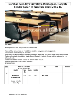


© Copyright 2026