
PB 4449 NOTE: FOLLOW THIS PLAN TO BUILD
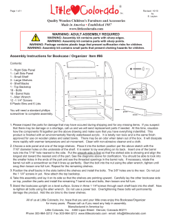
R
PB 4449
check out http://www.swing-n-slide.com
for updates to these instructions.
NOTE:
FOLLOW THIS
PLAN TO BUILD
ENTIRE UNIT
29'
26'
ASSEMBLY INSTRUCTIONS
No. of Children: Up to 10
Min. Use Zone: 29' x 26'
Set Dim. 12'W x 14'L x 10'H
Est. Building Time: 2 hrs (Tower only.)
Swing•N•Slide • 1212 Barberry Drive • Janesville, Wisconsin 53545
Visit our web site at: www.swing-n-slide.com or call us at 1-800-888-1232
R
Safety Checklist for Swing-N-Slide Play Sets and Accessories
Observing the following statements and warnings reduces the likelihood of serious or fatal injury
Installation Safety – Have You:
Consulted the assembly instructions supplied with your particular model?
Noted this accessory is to be used only on Swing•N•Slide approved designs? (Do not alter its design or add/remove components.)
Made sure all hardware is tightened securely? (Supplied bolt covers must also be fastened securely.)
Using a hacksaw, cut off all protruding threaded ends of bolts and other fasteners and remove any sharp edges with
a metal file as needed, and coated fastener ends with lead free paint?
Placed the equipment on level ground, not less than six feet (1.8 meters) from any structure or obstruction such as a fence, garage,
house, overhanging branches, laundry lines, or electrical wires?
Made sure home playground equipment is not installed over concrete, asphalt, packed earth or any other hard surface? (A fall onto
a hard surface can result in serious injury to the equipment user.)
Verified that suspended climbing ropes, chain,or cable are secured at both ends?
Consulted in assembly instructions of your particular model for minimum use zones?
Used a water sealant on your play set to protect the wood and prevent cracking and warping?
Followed all anchoring and shock absorbing surfacing requirements on the back of this sheet as they apply?
Made sure not to allow children to use equipment until it is properly installed?
Made sure to adjust all swings so there is a minimum 8'' clearance between the swing and the ground surface?
Operating Safety – Have You:
Determined that on-site adult supervision is provided for children of all ages?
Warned children the following before allowing them to use the equipment?
Not to walk close to, in front of, behind or between moving items.
Not to twist swing or any other accessory chains or ropes or loop them over the top support bar since this will reduce the
strength of chain or rope.
Not to swing empty seats or other accessories.
Not to slide down swing chains.
Be sure to sit in the center of the swing seat and other accessories with full weight on the seat.
Not to attach items to the playground equipment that are not specifically designed for use with the equipment such as but not
limited to, jump ropes, clotheslines, pet leashes, cables and chain. They may cause a strangulation hazard.
Not to climb or walk on the top of swing beams, railings or roof.
Not to use equipment in a manner other than intended.
Not to get off equipment while it is in motion.
Not to climb on the equipment when it is wet.
Be sure to go down slides feet first.
Determined that only one child per planned occupant seat should be allowed on this set at one time.
Determined children must be dressed appropriately for play. Avoid hooded jackets, bicycle helmets, clothing with draw strings and
loose fitting clothes which could become entangled or snagged on equipment.
Determined that suspended climbing ropes, chain, or cable cannot be looped back upon itself.
Made certain the slide is placed so that is is not in direct sunlight.
Safety Maintenance – At the beginning of every season and twice monthly thereafter:
Rake and check depth of loose fill protective surfacing material to prevent compaction and maintain appropriate depth. Replace as
necessary.
Check all nuts, bolts and C-Links during the usage season for tightness and tighten as required. (It is
particularly important that this procedure be followed at the beginning of each season.)
To prevent the deterioration of materials, remove plastic swing seats and other plastic accessories when outdoors temp dips down to
or below 32° F and take indoors.
Oil all metallic moving parts monthly during usage period.
Check all hardware and equipment for sharp edges during usage season. (Replace when necessary. It is especially
important to do this at the beginning of each new season.)
Check swing seats, chains, ropes and cables monthly during usage season for evidence of deterioration. Severe rusting or excessive wear,
especially near the top swing hanger or at the seat connection are evidence of chain deterioration. Cracks in the protective plastic sleeve
or seat itself are also signs of deterioration. If any of these conditions exist, call 1-800-888-1232 to order replacement accessories.
Sand rusted metal parts and repaint using non-lead based paint.
Check all wood members for deterioration and splinters. Sand down splinters and replace deteriorating wood members.
Disposal Instructions
When the equipment is taken out of service, it must be disassembled and disposed of in such a way that no unreasonable hazards
will exist at the time the set is discarded.
Important! Additional Safety Instructions for all Swing-N-Slide Playground Equipment.
Save this instruction sheet in the event the manufacturer needs to be contacted.
2
This product is intended for single family home/residential use only and not intended for use in any public setting.
Placement in any public setting constitutes a misuse of this product.
IMPORTANT!
ADDITIONAL REQUIRED SAFETY INSTALLATION INSTRUCTIONS
According to ASTM requirements, all kits must be anchored to the ground and, if the unit has a climbing rope, the rope end must be anchored to the ground. If soil conditions
permit stakes to be pulled out easily, cementing into ground is necessary.
• To anchor the unit to the ground, Follow the instructions included in this plan for applying Anchor-It devices to your unit, or use 2" x 4" x 18" (45mm x 95mm x 457mm) pressuretreated stakes. Pound stakes into ground at least 12" (305mm) at all inside corners of the posts (including A-frame legs and climbing unit posts). Attach with four (4) 16D (3-1/2")
galvanized nails per stake into each tower and/or A-frame upright.
• If the unit has a climbing rope, anchor the rope end.
• Once the unit is completely assembled and before children are allowed to play on it, proper shock-absorbing surfacing material must be installed. This may be accomplished by
using loose-fill materials at a sufficient depth. The Consumer Product Safety Commission “Handbook for Public Playground Safety” lists the following materials and required
depths that are sufficient for home/residential application. For fall height protection up to 9 ft. (2.742m) [recommended for Swing•N•Slide kits]:
1
LOOSE FILL MATERIAL
REQUIRED (UNCOMPRESSED) DEPTH in. (mm)
Wood Mulch
Double Shredded Bark Mulch
Uniform Wood Chips
Fine Sand
Fine Gravel
9" (229mm)
9" (229mm)
12" (305mm)
12" (305mm)
12" (305mm)
These depths were derived from the CPSC Handbook. Swing•N•Slide has not done independent tests to determine these required depths.
When properly installed, shock absorbing material will completely cover the horizontal baseboards on climbing units. This protective surfacing must extend a minimum of 6 ft.
(1.828m) in all directions from the perimeter of the equipment or from the outermost edges of any component. For example, a slide extending beyond the platform must have
protective surfacing at least 6 ft. (1.828mm) out from both sides as well as the end. For swings, the protective surface must extend at least 14 ft. (6m) out from both the back and
front of the swing when the swing is in its rest position.
For further information on playground safety, the Consumer Product Safety Commission
(CPSC) publishes the Outdoor Home Playground Safety Handbook which can be downloaded for free
from www.cpsc.gov. An additional resource is the American Society of Testing and Materials (ASTM)
Standard Consumer Safety Performance Specification for Home Playground Equipment (ASTM F1148)
which can be purchased and downloaded from www.astm.org.
Swing-N-Slide® MANUFACTURERS LIMITED WARRANTY
Swing-N-Slide® takes great pride in the quality and durability of our products. Our Manufacturer’s Limited Warranty provides confidence and demonstrates our commitment
to providing quality residential playground products.
MANUFACTURER’S LIFETIME LIMITED WARRANTY
Swing-N-Slide® warrants its thermoformed slides and climbing mountains to be free from defects in workmanship and materials, under normal use and conditions, for the
lifetime of the product.
MANUFACTURER’S 5 YEAR LIMITED WARRANTY
Swing-N-Slide® warrants its Custom Ready-to-Build Play Set kits and accessories to be free from defects in workmanship and materials, under normal use and conditions,
for a period of 5 years.
MANUFACTURER’S 5 YEAR LIMITED WARRANTY
Swing-N-Slide® warrants its No-Cut and Wood Complete Ready-to-Assemble Play Set kits against wood rot and termite damage, and to be free from defects in
workmanship and materials, under normal use and conditions, for a period of 5 years for structural wood components.
Cosmetic defects that do not affect the structural integrity of the product, or natural defects of wood such as warping, splitting, checking, twisting, shrinkage, swelling or
any other physical properties of wood that do not present a safety hazard, are not covered by this warranty.
MANUFACTURER’S ONE YEAR WARRANTY
Swing-N-Slide® warrants its canopy roofs and/or tarps, and Timber GLOVE lumber wrap to be free from defects in workmanship and materials, under normal use and
conditions, for a period of one year.
Swing-N-Slide® will repair, or at its discretion, replace any part within the stated warranty period which is defective in workmanship or materials. This decision is subject
to verification of the defect upon delivery of the defective part to Swing-N-Slide® at 1212 Barberry Drive, Janesville, Wisconsin, 53545. Any part(s) returned to Swing-NSlide® must have prior approved Return Authorization Number and proof of purchase, including the date of purchase. This warranty is valid only if the product is used for
the purpose for which it was designed and installed at a residential, single family dwelling. This warranty is void if the product is put to commercial or institutional use. This
warranty does not cover (a) products which have been damaged by acts of Nature, negligence, misuse, or accident, or which have been modified or repaired by
unauthorized persons; (b) the cost of labor; or the cost of shipping the product, any part, or any replacement product or part.
Swing-N-Slide® DISCLAIMS ALL OTHER REPRESENTATIONS AND WARRANTIES OF ANY KIND, EXPRESS, IMPLIED, STATUTORY OR OTHERWISE, INCLUDING THE
IMPLIED WARANTIES OF MERCHANTIBILITY AND FITNESS FOR A PARTICULAR PURPOSE. Swing-N-Slide® WILL NOT BE LIABLE FOR ANY INCIDENTAL OR
CONSEQUENTIAL DAMAGES. This warranty is non-transferable and does not extend to the owners of the product subsequent to the original purchaser. Some states do not
allow limitations on implied warranties or exclusion of incidental or consequential damages, so these restrictions may not be applicable to you. This warranty gives you
specific legal rights. You may also have other rights, which vary from state to state.
This warranty also does not apply to:
• Structures not erected, maintained or inspected in conformance with Swing-N-Slide® installation plans
• Structures that have had parts added or substituted not in conformance with Swing-N-Slide® installation plans
• Parts that have been modified, altered or misused
• Parts that have not been used as designed or intended
• Damage due to acts of Nature, vandalism, abnormal use or abuse as determined by Swing-N-Slide®
3
TOOLS REQUIRED • HERRAMIENTAS REQUERIDAS • OUTILS REQUIS
TOOLS REQUIRED
ELECTRIC DRILL
TAPE MEASURE
(40) 1-1/4" lag screw
HAMMER
1/2" SOCKET & WRENCH
SAFETY GLASSES
& DUST MASK
PHILLIPS BIT
CARPENTER'S SQUARE
(4) 5/16''Hex Head Lag Screws
(8) Tarp Washers
24) 2" lag screw
(4) 5/16'' flat washers
(8) 3/4'' panhead screws
(8) 3/4'' screws
(1) 3/8" DRILL BIT
(138) 1-1/4'' screws
(30) 1-1/2'' screws
(220) 2-1/2'' screws
(6) 3'' screws
(1) T20 Torx® Bit
4
(1) T30 Torx® Bit
(2) Step Brackets
Note: (1 Left, 1 Right)
(8) Shelf-Loc
THIS PRODUCT IS
INTENDED FOR USE
BY CHILDREN FROM
AGES 2-10 YEARS
(4) Wrap-Loc
For Home / Residential
Use ONLY
R
1212 Barberry Drive
Janesville, WI 53545
1-800-888-1232
(2) Roof Support Plate
www.swing-n-slide.com
(2) Name Plate
(1) Pleated Tarp
(4) 13-3/4'' Metal Rungs
(1) Window Frame
(2) Play Handles
Assembly
Plan
(8) Anchor-It
(1) Plan
5
(8) Anchor-It Straps
Assembly Instructions
(2) 1/2'' Panhead Screw
(16) 2'' Lag Screw
(4) 3/4'' Panhead Screw
(4) 1-1/2'' Lag Bolt
(1) T20 Torx® Bit
(2) 1-3/4'' Panhead Screw
(2) 1/4'' Flat Washer
(6) 1-1/4'' Wood Screw
(54) 2'' Wood Screw
(4) 5/16'' Flat Washer
(1) T30 Torx® Bit
(96) 2-1/2'' Wood Screw
(18) 1-1/4'' Lag Screw
(2) EZ Frame Brace (R)
(4) Tarp Washer
(3) 'L' Bracket
(2) EZ Frame Brace (L)
(1) PlayfulPlatform Tarp
(1) Play Handle
6
Assembly Instructions
Tower Board List
(1) 2'' x 4'' x 17'' (Slide Stake)
N O M IN AL M AT E R IAL S IZ E
(2) 2'' x 4'' x 31-1/2''
(2) 2'' x 4'' x 35''
(1) 2'' x 4'' x 33''
(5) 2'' x 4'' x 47-1/2''
(1) 2'' x 3'' x 47''
(1) 2'' x 3'' x 59''
LIS T E D S IZ E
T R U E S IZ E
E nglish(*)
M etric(C m )
E nglish(*)
M etric(C m )
1x4
2.5x7.6
3/4x3-1/2
1.9x9
1x6
2.5x15.3
3/4x5-1/2
1.9x14
5/4x4
3.2x10.2
1x3-1/2
2.5x9
2.5x14
5/4x6
3.2x15.3
1x5-1/2
2x2
5x5
1-1/2x1-1/2
3.8x3.8
2x3
5x7.6
1-1/2x2-1/2
3.8x6.4
2x4
5x10
1-1/2x3-1/2
3.8x9
3.8x14
2x6
5x15.3
1-1/2x5-1/2
7.6x7.6
3x3
7.6x7.6
3 x3
4x4
10x10
3-1/2x3-1/2
9x9
(*) E stim ated S izing D ue to C utting P rocess
(2) 5/4'' x 4'' x 20'' Angle Brace
(4) 5/4'' x 4'' x 14'' Ladder Brace
(4) 5/4'' x 4'' x 46-1/4'' Ladder Brace
(1) 5/4'' x 3'' x 38-1/2''
(1) 1'' x 4'' x 7'' Window Top
(1) 1'' x 4'' x 10'' Window Sill
(1) 1'' x 4'' x 11''
(1) 1'' x 4'' x 13-1/2''
(2) 1'' x 4'' x 15-1/2''
(2) 1'' x 4'' x 15-1/4'' Shutter
(1) 1'' x 4'' x 19-3/4''
(1) 1'' x 4'' x 20-1/2''
(1) 1'' x 4'' x 25-3/4''
(22) 1'' x 4'' x 33''
(2) 1'' x 4'' x 33'' Window Sides
(2) 1'' x 4'' x 41-1/4''
(4) 1'' x 4'' x 46''
(21) 1'' x 4'' x 47-1/2''
(4) 3'' x 3'' x 94'' (Plastic Coated)
7
Assembly Instructions
Platform Board List
N O M IN AL M AT E R IAL S IZ E
(1) 1’’ x 4’’ x 18’’
LIS T E D S IZ E
T R U E S IZ E
E nglish(*)
M etric(C m )
E nglish(*)
M etric(C m )
1x4
2.5x7.6
3/4x3-1/2
1.9x9
1x6
2.5x15.3
3/4x5-1/2
1.9x14
5/4x4
3.2x10.2
1x3-1/2
2.5x9
2.5x14
5/4x6
3.2x15.3
1x5-1/2
2x2
5x5
1-1/2x1-1/2
3.8x3.8
2x3
5x7.6
1-1/2x2-1/2
3.8x6.4
2x4
5x10
1-1/2x3-1/2
3.8x9
3.8x14
2x6
5x15.3
1-1/2x5-1/2
7.6x7.6
3x3
7.6x7.6
3 x3
4x4
10x10
3-1/2x3-1/2
9x9
(*) E stim ated S izing D ue to C utting P rocess
(1) 1’’ x 4’’ x 19’’
(12) 1’’ x 4’’ x 21’’
(1) 1’’ x 4’’ x 24’’
(2) 1’’ x 4’’ x 27’’ Angle Cut
(1) 5/4’’ x 4’’ x 10’’ Angle Cut
(2) 5/4’’ x 4’’ x 16’’
(3) 5/4’’ x 4’’ x 24’’
(1) 2’’ x 4’’ x 13-5/8’’
(2) 2’’ x 4’’ x 18’’
(2) 2’’ x 4’’ x 46’’
(4) 2’’ x 4’’ x 94’’
(1) 2’’ x 4’’ x 12’’ Slide Stake
(2) 5/4’’ x 2-1/2’’ x 19’’
(2) 5/4’’ x 2-1/2’’ x 48’’
(1) 4’’ x 4’’ x 10’’ Angle Cut
8
Assembly Instructions
How to select the correct fastener
Use these 2 pictorial guides to help select the correct fastener(s) for the
lumber attachment you are making. Each diagram will highlight the correct
number of fasteners to use, and where to attach them.
1'' x 4'' to 3'' x 3''
(3) 2-1/2'' screws
Apply 2-1/2" screws to the 1''x4'' boards
when attaching to 3''x3'' uprights.
1'' x 4'' to 1'' x 4''
(2)
1-1/4'' screws
Use 1-1/4'' screws when mounting 1'' x 4''
boards to 1''x4'' boards.
9
Assembly Instructions
ASSEMBLY INSTRUCTIONS • INSTRUCCIONES PARA ARMAR • DIRECTIVES D’ASSEMBLAGE
Understanding how the Bracket System Works
Example of a Shelf-Loc bracket connection.
2
1
Shelf-Loc Bracket
4
3
CORRECT!
Wrap-Loc
WRONG!
Brackets
''clipped''
brackets NOT
interlocked!
Example of a Shelf-Loc bracket connection.
Look for ''TOP'' stamp on
bracket for correct orientation.
TOP
Top of bracket
Introduction to the Bracket system
Wrap-Loc
1. ALWAYS Use 1-1/4'' or 2'' lag screws on
all brackets.
2. Brackets ''clip'' to each other. NEVER
position in a non-interlocking position.
NOTE: PLACE SCREWS IN BRACKETS ONLY
WHERE INSTRUCTED. DO NOT
FILL EVERY HOLE IN BRACKET.
THIS WILL LEAD TO HARDWARE
SHORTAGES.
GA
P
Bottom of bracket
(Hole locations close to bottom)
Shelf-Loc
Brackets Clip Together
10
DO NOT USE LAG
SCREWS HERE
Use Lag Screws Only Where
Brackets Attach
Assembly Instructions
TO
P
Look for ‘’TOP’’
stamp on brackets
while installing.
GAP on
this side
Frame 1 Construction Without PB 8263 Swing Beam
DO NOT USE LAG
SCREWS HERE
Fig.1a
Fig.1b
Use Lag Screws Only Where
Brackets Attach
3'' x 3'' x 94''
(2)
1-1/4'' Lag
Screws
per joint
(2)
1-1/4'' Lag Screws
per joint
47-1/4''
e1
m
Fra
Frame 1 Construction Without PB 8263 Swing Beam
1. Measure and position brackets on 3'' x 3'' as shown in (Fig.1a).
1-1/4'' Lag screw
Note: Secure Shelf Lock with (2) Lag Screws only at this time.
11
Assembly Instructions
TO
P
Look for ‘’TOP’’
stamp on brackets
while installing.
GAP on
this side
Frame 1 Construction With PB 8263 Swing Beam
Fig.1d
lag screw to
hold in place
(back)
DO NOT USE LAG
SCREWS HERE
Fig.1e
3'' x 3'' x 94''
NOTE: These
Brackets are included
in the PB 8263 Swing
Beam Kit
Use Lag Screws Only Where
Brackets Attach
(2)
2'' Lag Screws
per joint
(2)
1-1/4'' Lag Screws
per joint
84-1/2''
Fig.1f
47-1/4''
(2)
1-1/4'' Lag
Screws
per joint
e1
m
Fra
Frame 1 Construction With PB 8263 Swing Beam
1-1/4'' Lag screw
1. Measure and position brackets on 3'' x 3'' as shown in (Fig.1d).
Note: Secure Shelf Lock with (2) Lag Screws only at this time.
2'' Lag screw
12
Assembly Instructions
Frame 1 Construction
•WARNING•
Avoid splitting your
lumber by offsetting
your screws at least
3/4’’ from edge.
(3)
2-1/2'' screws
(per joint)
Fig. 2
x
1''
4''
2''
-1/
7
x4
Tip: Flex brackets to make installation of
2'' x 4'' easier
(3)
2-1/2'' screws
per joint
(2) 1-1/4'' lag screws
and
(3) 2'' lag screws
per bracket
x
2''
4''
2''
-1/
7
x4
Double check to make
sure structure is square
Fig. 2a
Approx. 1/4''
(3)
2-1/2'' screws
(per joint)
Fig. 2b
STEP
BRACKET
5/4'' x 4'' x 20''
Angle Brace
(6)
1-1/4'' screws
(per Bracket)
''
x4
'
'
1
(3)
2-1/2'' screws
per joint
2''
-1/
7
x4
Fig. 2c
e1
m
Fra
1-1/4'' Lag screw
1-1/4'' screw
2'' Lag screw
2-1/2'' screw
Frame 1 Construction cont.
2. Attach boards as shown in (Fig. 2) through (Fig. 2c).
13
(2)
1-1/4'' Lag
(3)
2'' Lag
NOTE: Upper screws are (2) 1-1/4'' Lag
Screws, Lower screws are (3) 2'' Lag
Screws.
Assembly Instructions
TO
P
Look for ‘’TOP’’
stamp on brackets
while installing.
GAP on
this side
Frame 2 Construction
Fig. 3
DO NOT USE LAG
SCREWS HERE
Fig. 3a
3'' x 3'' x 94''
Use Lag Screws Only Where
Brackets Attach
(2)
1-1/4'' Lag Screws
per joint
(2)
1-1/4'' Lag
Screws
per joint
47-1/4''
e2
m
Fra
Frame 2 Construction
1. Measure and position brackets on 3'' x 3'' as shown in (Fig.3).
1-1/4'' Lag screw
Note: Secure Shelf Lock with (2) Lag Screws only at this time.
14
Assembly Instructions
•WARNING•
Avoid splitting your
lumber by offsetting
your screws at least
3/4’’ from edge.
Frame 2 Construction
Fig. 4
1''
''
x4
2''
-1/
7
x4
(3)
2-1/2'' screws
(per joint)
Tip: Flex brackets to make installation of
2'' x 4'' easier
(3)
2-1/2'' screws
per joint
(2) 1-1/4'' lag screws
and
(3) 2'' lag screws
per bracket
2''
''
x4
Fig. 4a
2''
-1/
7
x4
Approx. 1/4''
Fig. 4b
(2)
1-1/4'' Lag
(3)
2'' Lag
NOTE: Upper screws are (2) 1-1/4'' Lag
Screws, Lower screws are (3) 2'' Lag
Screws.
x
1''
4''
2''
-1/
7
x4
e2
m
Fra
(3)
2-1/2'' screws
per joint
1-1/4'' Lag screw
Double check to make
sure structure is square
2'' Lag screw
Frame 2 Construction cont.
2-1/2'' screw
2. Attach boards as shown in (Fig. 4) through (Fig. 4b).
15
Assembly Instructions
Inset Board 3/4''
From Flush With
3''x 3'' Upright
Fig. 5
Inset Board 3/4''
From Flush With
3''x 3'' Upright
(3)
2-1/2'' screws
per joint
1''
x
1''
x
4''
x
4''
x
46
''
Tip: Flex brackets to make installation of
2'' x 4'' easier
46
''
2''
x
4''
x
Fig. 5a
47
-1/
2''
Approx. 1/4''
(2) 1-1/4'' lag screws
and
(3) 2'' lag screws
per bracket
Fig. 5b
2''
x
4''
x
47
-1/
2''
1''
x
4''
x
46
''
(3)
2'' Lag
e1
m
a
Fr
Inset Board 3/4''
From Flush With
3''x 3'' Upright
(3)
2-1/2'' screws
per joint
1''
x
4''
x
(2)
1-1/4'' Lag
NOTE: Upper screws are (2) 1-1/4'' Lag
Screws, Lower screws are (3) 2'' Lag
Screws.
46
''
Inset Board 3/4''
From Flush With
3''x 3'' Upright
1-1/4'' Lag screw
Frame Construction cont.
1. Attach 1''x4'' and 2''x4'' boards as shown.
2'' Lag screw
2-1/2'' screw
16
Assembly Instructions
Tip: Flex brackets to make installation of
2'' x 4'' easier
Inset Board 3/4''
From Flush With
3''x 3'' Upright
Fig. 6
(3)
2-1/2'' screws
per joint
Fig. 6a
Approx. 1/4''
47
-1/
2''
Ou
tsid
et
oO
uts
ide
Fig. 6b
(2)
1-1/4'' Lag
(2) 1-1/4'' lag screws
and
(3) 2'' lag screws
per bracket
(3)
2'' Lag
NOTE: Upper screws are (2) 1-1/4'' Lag
Screws, Lower screws are (3) 2'' Lag
Screws.
Fig. 6c
e1
m
Fra
47
-1/
2''
Ou
tsid
e
to
Ou
tsid
e
1''
x
e2
m
Fra
(3)
2-1/2'' screws
per joint
1-1/4'' Lag screw
1. Attach Frame 2 to Frame 1 as shown.
2. Install 1''x 4'' as shown in (Fig. 6c).
Note: Outside to Outside measurement of
uprights on all four sides of the tower
should be 47-1/2''
13
-1/
2''
(4)
1-1/4'' screws
Inset Board 3/4''
From Flush With
3''x 3'' Upright
Frame Construction (cont.)
4''
x
2'' Lag screw
1-1/4'' screw
2-1/2'' screw
17
Assembly Instructions
Fig. 7
Fig. 7a
(2)
2-1/2''
screws
per joint
1''
x
FR
ON
T
4''
x
1''
x
20
''
41
-1/
4''
x
2''
4''
x
4''
(2)
2-1/2''
screws
per joint
41
-1/
4''
'
/2'
7-1
4
x
(4)
1-1/4''
screws
1''
x
4''
x
19
-3/
4''
FR
ON
T
UNDER DECK VIEW
1-1/4'' screw
2-1/2'' screw
Install Deck Boards
1. Install (2) 1'' x 4'' deck boards as shown in (Fig. 7).
2. Attach 2'' x 4'' to deck boards using 2-1/2'' screws as shown in (Fig. 7).
3. Attach 1'' x 4'' Slide Support as shown in (Fig. 7a).
18
Assembly Instructions
Fig. 8
(2)
2-1/2''
screws
per joint
(10
)1
'' x
4''
x
47
-1/
2''
NOTE: There must be a 1/2''
Nominal Gap between all
deck boards.
2-1/2'' screw
Install Deck Boards
1. Install (10) 1'' x 4'' deck boards to structure as shown (Fig. 8).
2. Use two 2-1/2'' screws at center and each end of deck boards.
Note: Screws at center will attach to center support.
19
Assembly Instructions
NOTE: If you are not attaching a Swing Beam to
your unit, skip ahead to (Fig. 15)
Fig. 9a
Fig. 9
Tip: Flex brackets to make installation of
2'' x 4'' easier
Fig.
9b
Fig. 3a
Approx. 1/4''
Fig. 9c
4''
x
ATTENTION:
Unit has been rotated
1/4 turn Counter
Clockwise for this view.
2'' Lag screw
Install Lower Rail Boards
1. Install shelf brackets as shown in (Fig. 9) and
(Fig. 9a).
2. Install 4’’ x 4’’ Swing Beam Support as shown in
(Fig. 9b) and (Fig. 9c).
20
4''
x
47
-1/
2''
Assembly Instructions
START OF PLAYFUL PLATFORM
ASSEMBLY
Fig. 10
5/4'' x 4'' x 10'' Angle
(3)
2'' screws
NOTE:
Double check your
measurements to make
sure the structure is
square.
Note: Screws Must Be
Driven Through 5/4'' x 4''
Into The 2'' x 4''.
(3)
2'' screws
per joint
2''
-1/
75
2'' x 4'' x 46''
x
2''
2''
x
8''
-5/
50
''
94
4''
x
x
4''
94
''
(3)
2-1/2'' screws
per joint
1'' x 4'' x 27'' Angle
92-5/8''
Frame 1
Frame Assembly:
2'' Wood Screw
1. Install (1) 5/4'' x 4'', (1) 1'' x 4'' and (1) 2'' x 4'' boards as shown
in (Fig. 10).
2-1/2'' Wood Screw
21
Assembly Instructions
Fig. 10a
2'' x 4'' x 13-5/8'' Angle
(3)
2-1/2'' screws
per joint
''
86
Frame 2
Frame Assembly Cont.:
1. Install (1) 2'' x 4'' as shown in (Fig. 10a).
2-1/2'' Wood Screw
22
Assembly Instructions
Fig. 11
(3)
1-1/4'' Lag screws
per joint
3 5/8
3-5/8''
Frame 2
Swing Beam Support:
1. Install Swing Support Bracket as shown in (Fig. 11).
1-1/4'' Lag Screw
23
Assembly Instructions
Fig. 12
3''
(3)
1-1/4'' Lag screws
per Bracket
4''
x
4''
x
10
'' A
ng
le
Fig. 12a
(3)
2-1/2'' wood screws
per joint
4'' x 4'' x 10'' Angle
Fig. 12b
(3)
1-1/4'' Lag screws
per joint
UNDERSIDE VIEW
Frame 2
Swing Beam Support Cont.:
2-1/2'' Wood Screw
1-1/4'' Lag Screw
1. Attach (2) “L” Brackets as shown in (Fig. 12).
2. Secure Assembly in place on Frame as shown in (Fig. 12a).
3. Finish securing Assembly in place with Metal Bracket as shown in
(Fig. 12b).
24
Assembly Instructions
DETAIL VIEW
UNIT ROTATED 180˚
Fig. 13a
(2)
2-1/2'' wood screws
per joint
5/4
'' x
4''
x
Double check to make
sure structure is square
24
''
Fig. 13
10-3/4''
(2)
2-1/2'' wood screws
per joint
10''
2''
''
5/4
'' x
x4
'' x
x4
''
24
''
18
2''
'' x
x4
''
18
10''
(2)
2-1/2'' wood screws
Frame 1
1''
'' x
x4
''
24
Install Frame Braces:
2-1/2'' Wood Screw
1. Install (1) 1'' x 4'', (1) 5/4'' x 4'', and (2) 2'' x 4'' boards as shown
in (Fig. 13), and (Fig. 13a).
25
Assembly Instructions
Fig. 14
(2)
2-1/2'' wood screws
per joint
Platform Assembly:
2-1/2'' Wood Screw
1. Lift second half of Platform and secure in place in (4) locations as
shown in (Fig. 14).
26
Assembly Instructions
Fig. 15
(2)
2-1/2'' wood screws
per joint
(12) 1'' x 4'' x 21''
NOTE: There must be a 3/8''
Nominal Gap between
deck boards.
Install Deck:
2-1/2'' Wood Screw
1. Install Deck boards, evenly spaced with a 3/8'' Gap, as shown in
(Fig. 15).
27
Assembly Instructions
NOTE:
Double check your
measurements to make
sure the boards are
square.
Fig. 16
241/4
''
(2)
5/4
'' x
373/4
''
(2)
2-1/2'' wood screws
per joint
4''
x
24
''
Install Step Rungs:
2-1/2'' Wood Screw
1. Install Step Rungs as shown in (Fig. 16).
28
Assembly Instructions
platform 2
Swing Beam Assembly
3/8’’ Hole Locations
1. Identify your 3'' x 5-1/2'' x 94'' Swing Beam by
locating the board with the holes predrilled as
shown in (Fig. 17).
94''
94''
3''
platform
tower 1
29
Fig. 17
Assembly Instructions
Hammer
Fig. 17a
3/8'' hole
T-nut
t-nut
Bottom Beam Clamp
(4) 1-1/4'' screws
Use Screwdriver to aid in tightening
Swing Hanger
Swing Hanger Assembly
1. Tap T-nut into 3/8’’ hole as shown in (Fig. 17a).
2. Place a bottom beam clamp over the swing hanger as shown in (Fig. 17a).
3. Insert the swing hanger into the beam and thread it into the T-nut until it is flush or near flush with the top of the
T-nut. A screwdriver may be used to twist the hanger (Fig. 17a). Orient swing hanger as shown in (Fig 17a).
4. Use (4) 1-1/4'' screws to secure beam clamp.
5. Check hanger to ensure it does not spin.
6. Repeat for all swing hangers.
30
Assembly Instructions
A-Frame Assembly cont.
Fig. 18
1. Position Split-Brackets on 4'' x 4'' x 47-1/2''
(Fig 18).
2. With the help of others, lift A-Frame and
Swing Beam Assembly and center onto unit as
shown in (Fig. 18).
3. Secure as shown in (Fig 18a).
''
22
Fig. 18a
am
e
B
g
in
w
S
View from Deck
2'' Lag screw
x 8 (each bracket)
31
Sw
ing
Be
am
Assembly Instructions
Fig. 18b
Swing BEam Attachment cont.
m
ea
B
ing
w
S
1. With the help of others, place Swing Beam as
shown in (Fig. 18b).
3. Secure as shown in (Fig 18c).
Platform
Fig. 18c
am
e
B
g
n
i
Sw
View from Deck
1-1/4'' Lag Screw
x 3 (each bracket)
32
Assembly Instructions
Fig. 19
(3)
2-1/2'' screws
per joint
x
1''
(2)
4''
2''
-1/
7
x4
9''
2-1/2''
Fig. 19a
1''
(8)
(2)
1-1/4'' deck screws
per joint
NOTE: There must be a 1-1/2''
Nominal Gap between all
barrier boards.
2-1/4''
1-1/4'' screw
2-1/2'' screw
IInstall Barrier
1. Attach 1'' x 4'' support boards as shown in (Fig. 19).
2. Attach (8) 1'' x 4'' Barrier Boards, evenly spaced, as
shown in (Fig. 19a).
33
'' x
x4
''
33
Use 2-1/2'' screws to
secure to 1'' x 4'' to 4'' x 4''
Assembly Instructions
Fig. 20
(3)
2-1/2'' screws
per joint
x
1''
(3)
4''
2''
-1/
7
x4
29-1/2''
Fig. 20a
1''
x
1''
x
4''
x
4''
x
25
-3/
4''
20
-1/
2''
(5)
2-1/2'' screws
per Board
Barrier Supports
1. Install 1'' x 4'' barrier support boards as
shown in (Fig. 20) and (Fig. 20a).
2-1/2'' screw
34
Assembly Instructions
Fig. 21
Use 1-1/2'' screws from outside
barrier to
secure to 2'' x 4'' to 1'' x 4''
NOTE: There must be a 1''
Nominal Gap between
rear barrier boards.
(1) 1'' x 4'' x 7''
Window Top
(Flush With
Barrier Boards)
(2) 1'' x 4'' x 33''
(4) 1'' x 4'' x 33''
(1) 2'' x 4'' x 33''
(2)
1-1/4'' deck screws
per joint
(2) 1'' x 4'' x 33''
Window Cut
(1) 1'' x 4'' x 11''
Window Bottom
Fig. 21a
(2)
1-1/4'' deck screws
per joint
NOTE: There must be no Gap
between front barrier
boards. Mount Flush.
3/4'' screw
(8)
3/4'' deck screws
1-1/4'' screw
1-1/2'' screw
Install Barrier
1. Attach 1'' x 4'' barrier boards as shown in (Fig. 21).
2. Install Window Frame, as shown in (Fig. 21a).
NOTE: You may need to readjust Window Top Board to
properly align Window Frame with Opening.
35
Assembly Instructions
Fig. 22
x
1''
4''
2''
-1/
7
x4
(3)
2-1/2'' screws
per joint
Fig. 22a
1''
(8)
(2)
1-1/4'' deck screws
per joint
NOTE: There must be a 1-1/2''
Nominal Gap between all
barrier boards.
Barrier Supports
1. Install 1'' x 4'' barrier support board and
barrier boards as shown in (Fig. 22) and
(Fig. 22a).
''
33
x
''
x4
1-1/4'' screw
2-1/2'' screw
36
Assembly Instructions
(6)
1-1/4'' screws
'x
2'
'x
4'
(2)
2-1/2'' screws
per joint
2'
'x
''
35
Fig. 23
4'
'x
X2
5/4
'' x
31
-1
/2
''
Use Guides On
Plate To Align
Triangle Brace
Fig. 23a
3''
x
38
-1/
2''
Fig. 23b
(2)
2-1/2'' screws
per joint
Note: Make certain top surface
is flush with A-Frame point.
Roof Support.
1. Assemble Tarp Frame as shown in (Fig. 23) through (Fig. 23b).
1-1/4'' screw
2-1/2'' screw
37
Assembly Instructions
Fig. 24
INSTALL THESE TWO
SCREWS FIRST
3/4'' screw
Fig. 24a
Install Canopy.
1. Install canopy as shown in (Fig. 24).
Note: Make Certain Pleats are facing outward when
canopy is installed.
Note: Canopy will overhang support boards approx.
1-3/4'' on both sides when properly installed.
2. Secure canopy in eight locations (Fig. 24a). Make
certain to install the top two screws first to help center
the Canopy on the frame.
38
Washer
3/4'' Screw
3 Per Side
Assembly Instructions
Fig. 25
(3)
2-1/2'' screws
per joint
1''
x
4''
x
47
-1/
2''
21-1/2''
Fig. 25a
(3)
1-1/4'' screws
per joint
1-1/4'' screw
2-1/2'' screw
Install Protective Board and Window Dressing
1. Secure protective 1'' x 4'' barrier board as shown in (Fig. 25).
2. Attach Window Sill and Shutters as shown in (Fig. 25a).
39
Assembly Instructions
Fig. 26
1/4'' washer
1 - 3/4 Panhead screw
washer
1 - 3/4 Panhead screw
11"
1 - 3/4 Panhead screw
Deck Surface
Safety Handles.
1. Mount safety handles in the Ladder opening approximately11'' above the deck surface (Fig. 26).
40
Assembly Instructions
Fig. 27
Fig. 27a
(2) 1'' x 4'' x 15-1/2''
2-3/4''
9-7/8''
(2)
1-1/2'' screws
per joint
(2) 5/4'' x 4'' x 46-1/4''
Per Side
2'' x 3'' x 47''
2''
-1/
15
(6)
1-1/2'' screws
per side
21-7/8''
33-7/8''
(2)
1-1/4''
Lag screws
per rung
Body of Rung Must
Face Inward
(2)
2-1/2'' screws
per joint
ATTENTION:
These Images Show The
Back Side of The Unit
Fig. 27b
1-1/4'' Lag screw
1-1/2'' screw
(3)
3'' screws
per joint
2-1/2'' screw
3'' screw
Ladder Assembly.
1. Attach 2'' x3'' to unit as shown in (Fig. 27).
2. Assemble Ladder by Laminating 5/4'' x 4'' x 46-1/4'' boards as shown in (Fig. 27a). Make certain to
measure the spacing of the ladder rungs accurately to avoid a bad opening.
3. Attach the ladder to the unit as shown in (Fig. 27b).
Note: To avoid a possible entrapment issue, make sure to attach the Ladder Rung so that the body of the Rung
is facing inward (towards the underside of the unit).
41
Assembly Instructions
Slide Installation.
Fig. 28
1. Install Slide centered in the provided
opening as shown in (Fig. 28).
2. Attach Stake to end of slide as shown in
(Fig. 28a).
Fig. 28a
(2)
1-1/4'' screws
per joint
2'' x 4'' x 17''
2'' Above Ground
1'' Truss Screw
Use truss head screws to
to secure slide to deck.
Anchor-It
Fig. 29
Anchor-It Installation.
Instructions
Flat Washer
metal
strap
1-1/2"
lag bolt
for Anchoring Swing•N•Slide Activity Centers
1. Determine the final location of your activity center.
2. Place the Anchor- It stakes adjacent to the base and near the corners of
your activity center (at the bottom of the legs on swing sets) and twist the
auger- style stakes into the ground until only the loop is exposed.
3. Place the metal strap through the loop of the Anchor- It stake and secure
it to the unit with a lag screw and washer as illustrated to the right.
Note: Attach the strap to the unit with as little play as possible using
whatever holes in the strap that work best.
Anchor-It
42
Assembly Instructions
Fig. 30
HANG ACCESSORIES AND FULLY
CLOSE ‘S’ HOOKS.
(4)
2'' Lag Screws
AND
(4)
2'' wood screws
per Brace
(1) Brace per side
of unit
/2''
1-1
Install EZ-Frame Braces:
2'' Wood Screw
1. Install (1) EZ-Frame Braces per side of the units as shown in
(Fig. 30).
2. Hang Swing Accessories and fully close ‘S’ Hooks using pliers.
2'' Lag Screw
43
Assembly Instructions
Fig. 31
Double check to make
sure boards are square
5/4
'' x
5/4
'' x
2-1
/2'
'x
FLUSH
2-1
/2'
'x
22
-1/
2''
48
''
48
''
(2)
2'' wood screws
per side
Secure Tarp Supports:
1. Secure Tarp Supports as shown in (Fig. 31).
2'' Wood Screw
44
Assembly Instructions
Fig. 32
(2)
2'' wood screws
per joint
'' x
5/4
'x
/2'
2-1
''
19
''
5/4
x
2''
-1/
x2
''
19
(2)
2'' wood screws
per joint
Tarp Support Installation Cont.:
1. Install Tarp support Cross Braces as shown in (Fig. 32).
45
2'' Wood Screw
Assembly Instructions
Fig. 33
Double check to make
sure boards are square
(2) 5/4'' x 4'' x 16''
(2)
2'' wood screws
per joint
22
-1/
4''
22
-1/
4''
Tarp Support Braces Cont.:
2'' Wood Screw
1. Install Vertical Tarp Supports as shown in (Fig. 33).
46
Assembly Instructions
Fig. 34
(2)
2'' wood screws
per joint
1''
'' x
x4
''
19
Tarp Support Braces Cont.:
2'' Wood Screw
1. Install Tarp Cross Brace as shown in (Fig. 34).
47
Assembly Instructions
Fig. 35
Fig. 35a
Washer
3/4'' Screw
2 Per Side
Secure Tarp:
1. Secure Tarp in Place as shown in (Fig. 35), and (Fig. 35a).
3/4'' screw
48
Assembly Instructions
Fig. 36
1''
x
4''
x
18
''
(4)
1-1/4'' wood screws
Secure Deck Support:
1. Secure 1'' x 4'' x 18'' Deck Support Board under the Platform Deck
as shown in (Fig. 36).
49
1-1/4'' Wood Screw
Assembly Instructions
THESE INSTRUCTIONS SUPERCEDE THE
PLAN INCLUDED WITH YOUR ROCK WALL KIT
Fig. 37a
Fig. 37
(16) 1'' x 4'' x 24''
2'' x 4'' x 56-3/4''
2'' x 4'' x 56-3/4''
(2)
2-1/2'' screws
per joint
3/4''
21''
1-1/2''
(2)
2-1/2'' screws
per joint
(2)
2-1/2'' screws
per joint
Rock Wall Assembly and Installation:
1. Assemble Rock as shown in (Fig. 37).
2. Install Rock wall on Unit as shown in (Fig. 37a).
2-1/2'' Wood Screw
50
Assembly Instructions
Fig. 38
Climbing Rock Installation
1. Mark locations of Climbing Rocks on the Climbing
Wall in a pattern that will easily allow your child to
climb to the deck. Make sure the bolt hole locations
are clear of wall supports before drilling.
(2)"T" nuts
2. Drill holes through the wall at the desired locations
using a 3/8" drill bit. Install Climbing Rocks as shown
in (Fig. 38).
3. Make sure the Climbing Wall and Climbing Rock
connections are secure before allowing any children to
play on the Climbing Wall.
Hold (rock)
3/8" Holes
(2) 1-1/4'' Hex Head Bolts
(1) Loc Washer per bolt
(1) Flat Washer per bolt
Anchor-It
Fig. 39
Anchor-It Installation.
Instructions
Flat Washer
metal
strap
1-1/2"
lag bolt
for Anchoring Swing•N•Slide Activity Centers
1. Determine the final location of your activity center.
2. Place the Anchor- It stakes adjacent to the base and near the corners of
your activity center (at the bottom of the legs on swing sets) and twist the
auger- style stakes into the ground until only the loop is exposed.
3. Place the metal strap through the loop of the Anchor- It stake and secure
it to the unit with a lag screw and washer as illustrated to the right.
Note: Attach the strap to the unit with as little play as possible using
whatever holes in the strap that work best.
Anchor-It
51
Assembly Instructions
Fig. 40
1-1/4'' Screw
THIS PRODUCT IS
INTENDED FOR USE
BY CHILDREN FROM
AGES 2-10 YEARS
For Home / Residential
Use ONLY
BLACK
R
1212 Barberry Drive
Janesville, WI 53545
1-800-888-1232
www
ID TAG:
.swing-n-slide.com
1. Secure your product ID tag onto easy to read
location of any 4'' x 4'' using (2) 1-1/2'' screws
as shown in (Fig. 40).
Safety Handle
Fig. 40a
Safety Handle:
1. Mount safety handle in the climber openings
approximately 11'' above the deck surface
(Fig. 40a).
1- 3/4
Panhead
screw
washer
11"
Deck Surface
1-3/4 Panhead screw
52
Assembly Instructions
53
Assembly Instructions
54
Assembly Instructions
55
Questions???...
Call our Customer Service Department
at 1-800-888-1232
R
© PlayCore Inc. 2011
Printed In USA
LA 6224


© Copyright 2026