
Thyro-AX - Advanced Energy
1 THYRO-AXTM THYRISTOR-LEISTUNGSSTELLER / THYRISTOR POWER CONTROLLER DEZEMBER 2014 / DECEMBER 2014 8000030962 DE/EN - V5 2 3 CONTENTS List of illustrations and tables Abbreviations Key features 5 6 7 1. Safety notes 1.1 Obligatory instruction 1.2 Appropriate usage 1.3 Residual hazards of the product 1.4 Incorrect operation and their consequences 1.5 Scope of supply 1.6 Storage 1.7 Assembly 1.8 Connection 1.9 Maintenance, service, faults 1.10 Replacement of the integrated semiconductor fuse 1.11 Shut down, dis-assembly 8 8 8 9 9 10 10 10 10 10 12 12 2. Safety requirements 2.1 Important instructions and explanations 2.2 General danger information 2.3 Qualified personnel 2.4 Requirements to the operator 2.5 Intended use 2.6 Liability 2.7 Guidelines 13 13 14 16 16 16 17 17 3. Notes on these operating instructions 3.1 Validity 3.2 Type designations 3.3 Handling 3.4 Loss of warranty 3.5 Copyright 3.6 Further information on copyright 18 18 18 19 20 20 20 4. Contact 4.1 Technical queries 4.2 Commercial queries 4.3 Service 4.4 Internet 21 21 21 21 21 5. Commissioning 5.1 Connections 5.1.1 Grounding 5.1.2 Power supply and load 5.1.3 Electronic supply 5.1.4 Fan 5.1.5 Control signals 5.1.6 USB interface 5.1.7 Connecting terminals (overview) 5.1.8 Connection diagrams 5.2 Load configuration 5.3 IP20 Protection 22 22 22 22 23 23 23 24 25 26 31 32 6. Description of functionality 6.1 Operating modes 6.1.1 Full wave mode TAKT 6.1.2 Phase angle firing VAR (only Thyro-AX 1A and 3A) 6.1.3 SST ramp in operating mode TAKT 6.1.4 Quick takt mode QTM (only Thyro-AX 1A) 6.1.5 Switch mode SWITCH 6.2 Setpoint processing 6.3 Control modes 6.4 Limitations 6.5 Pulse inhibition 6.6 Current and voltage transformer 6.7 Display via analog output 6.8 Fault, status and monitoring messages 6.8.1 Overview 6.8.2 Fault signaling relay K1 6.9 Monitoring 6.9.1 Monitoring the mains voltage 6.9.2 Device temperature monitoring 38 38 38 38 39 39 39 39 42 44 45 45 46 46 47 49 50 50 51 7. Display and operational elements 7.1 Operation of touch display 7.2 Actual value view and actual value button 7.3 Message overview and acknowledgment 7.4 EasyStart 7.5 EasyStart identification 7.6 Restriction codes for parameterization and digital setpoint 2 7.7 Save and load parameters with USB stick 7.8 Menu structure 7.9 Thyro-Tool AX 7.9.1 Manage device and files 7.9.2 Parameter 52 52 54 55 57 60 60 61 62 63 66 67 4 5 8. Mains load optimization 8.1 Internal mains load optimization 8.2 Synchronization with dASM module or dASM bus module 8.3 Synchronization with the Thyro-Power Manager 8.4 Software synchronization with solid delay 70 70 70 71 71 9. Load monitoring 74 10. Multi I/O 78 11. Dimension drawings 80 12. Technical data 12.1 Technical data 12.2 Approvals and conformity 12.3 Type overview 104 104 110 112 LIST OF ILLUSTRATIONS AND TABLES Fig. 1 Connection diagram Thyro-AX 1A Fig. 2 Connection diagram Thyro-AX 2A Fig. 3 Connection diagram Thyro-AX 3A with load in delta or star connection without N Fig. 4 Connection diagram Thyro-AX 3A with load in star connection with N Fig. 5 Connection diagram Thyro-AX 3A with load in open delta connection Fig. 6 Set point inputs and effective set point Fig. 7 Contact assignment fault signaling relay K1 Fig. 8 Examples of areas to be pressed for actual value button Fig. 9 Connection to local installed server Fig. 10 Several open tabs Fig. 11 Minimize status messages Fig. 12 Maximize status messages Fig. 13 Separate tab Fig. 14 Preview of arranged tabs Fig. 15 Open thyro files in file explorer Fig. 16 Change name of device (re-start is necessary) Fig. 17 Transfer of parameter file Fig. 18 Drop-down menu Fig. 19 Field Fig. 20 Checkbox Fig. 21 Example of 4 controllers Fig. 22 Internal mains load optimization Fig. 23 Thyro-Power Manager wiring diagram Fig. 24 Digital set point 2 via external buttons Tab. 1 Connecting terminals (overview) Tab. 2 Effects in the case of load resistance change Tab. 3 Effective limitations Tab. 4 Error Tab. 5 Status Tab. 6 Monitoring Tab. 7 Limits of mains voltage monitoring Tab. 8 Acknowledgment Tab. 9 Menu structure Thyro-AX Tab. 10 Load resistance Tab. 11 Multi I/O Tab. 12 Multi I/O signals Tab. 13 Connection data of the power connection Tab. 14 Tightening torques Tab. 15 Thyro-AX 1A …H RLP2 Tab. 16 Thyro-AX 2A …H RLP2 Tab. 17 Thyro-AX 3A …H RLP2 26 27 28 29 30 41 49 55 63 63 64 64 65 65 66 67 68 68 69 69 72 72 73 107 25 44 45 47 48 49 51 56 62 75 78 106 108 109 112 113 114 6 7 ABBREVIATIONS KEY FEATURES AN1 - phase angle of the 1st half wave SST - soft-start time SYT - synchronized clock T0 - cycle period TS - switch-on time TAKT - full wave mode Thyrotakt VAR - phase angle firing Thyrovar QTM - quick takt mode SWITCH - switch mode • Integrated semiconductor fuse • Type range 230-600 V~, 16-1500 A, single phase, two phase uand three phase • Load voltage from 24 V~ • Touch display capable of full graphics • Electronic supply with 230V~/110V~ (85 V-265 V permissible) • Ohmic load and transformer load as well as load with large Rwarm /Rcold (≤ 6) and configurable peak current limitation up to 3 x Inom in operating mode VAR. • Soft-start function for transformer load • Channel separation, needed in case of counter voltage • Load current monitoring • Measurement of real phase value (current, voltage, power and resistance) • Fuse monitoring • 5 Multi-I/Os • 1 signaling relay • 3 analog outputs • Flexible connection: supply and outflow from above or below as selected • Control modes U, U2, I, I2; P • Thyristor short circuit protection • Operating modes TAKT, VAR, SWITCH and QTM (QTM only in the case of the single phase device, VAR only in the case of the single and three phase device) •M ains load optimization: internal for operating modes QTM and TAKT, connection for external mains load optimization e.g. Thyro-Power Manager (QTM only in the case of single phase device) • Control by analog or digital setpoint, via PC, touch display or via optional bus adapter • Data logger • Operating hours counter • Energy counter • Internal/external measuring transformer • USB interface • Safe isolation in accordance with DIN EN 50 178 • UL approval (for standard devices 16 - 350A) Options: • Coupling to different bus systems e.g. PROFIBUS DPV1, Modbus RTU, DeviceNet, CANopen, PROFINET, EtherNet/IP and Modbus TCP. Other bus systems on request. • Connection for optional visualization and commissioning software Thyro-Tool AX via USB (optional also via RS-232 adapter).The Thyro-Tool Family can also be used to an certain extent. 8 9 1. SAFETY NOTES The safety notes and the operating instructions are to be read carefully before installing and commissioning. 1.1 OBLIGATORY INSTRUCTION These safety notes and operating instructions shall carefully be read by all persons deployed for work using and employing the Thyro-AX prior to assembly, installation and the initial start-up of the Thyro-AX. These operating instructions are part of the Thyro-AX. The operator of the device is committed to provide these operating instructions without limitation to all persons, who transport the Thyro-AX, start it up, maintain it, or perform other work tasks to it. In accordance with the Product Liability Act the manufacturer of this product is obligated to inform about and warn against • other than the intended use of a product • the residual hazards of a product as well as • incorrect usages and their consequences The following information is intended for this purpose. This information should warn the product user and protect him and his appliances. 1.2 APPROPRIATE USAGE The Thyro-AX is a power controller which is capable of communication. It can be used anywhere where alternating voltages, alternating currents or power need to be regulated in thermic process engineering. The Thyro-AX has several different operation and control modes, good connection to process and automatization technology, high regulation accuracy and simple handling. • The Thyro-AX is a component which may only be used to control and regulate electric energies in industrial alternating or three-phase networks. • The Thyro-AX may at most be operated with the maximum permissible connection values in accordance with the details on the type plate. • The Thyro-AX may only be operated in connection with an appropriate upstream mains disconnecting device (e.g. switch, take note of DIN EN 50110-1) • The Thyro-AX is not functional on its own and must be project planned for its appropriate usage in order to minimize the residual hazards of the product. • The Thyro-AX may only be used for the purpose for which it was intended, as persons may otherwise be exposed to dangers (e.g. electric shock, burns) and systems also (e. g. overload). • It is not permitted to make any unauthorized modifications to the device or to use any spare parts or replacement parts not approved by Advanced Energy, or to use the device for any other purpose. • The warranty obligations of the manufacturer are only applicable if these operating instructions are observed and complied with. • It must be ensured that in the case of an error no uncontrolled large currents, voltages of power can occur in the circuit. • In the case of an error even with appropriate usage it is possible that the currents, voltages or power in the load circuit are no longer affected by the device (example: in the case of the destruction of of the power components (fully alloyed or high resistance) the following reactions may result: current interruption, half wave operation, continual flow of energy). 1.3 RESIDUAL HAZARDS OF THE PRODUCT Even with intended use it is possible, in the case of an error, that the currents, voltages or power in the load circuit are no longer affected by the Thyro-AX. If the power components are destroyed, for example, the following cases are possible: current interruption, continual flow of energy. If such a case occurs, then the occurring load voltages and currents result from the physical sizes of the overall circuit. Throughout the project planning of the system it must be ensured, that no uncontrolled large currents, voltages or power can occur. 1.4 INCORRECT OPERATION AND THEIR CONSEQUENCES In the case of incorrect operations, higher power, voltages or currents than intended can reach the thyristor power controller or the load. This can cause damage to the thyristor power controller or the load. In particular, factory-set parameters may not be altered in such a way that the Thyro-AX is overloaded. 10 11 1.5 SCOPE OF SUPPLY The supply consists of the following parts: • Thyro-AX • Accessory bag with screw/push terminals • Operating instructions • Safety note stickers 1.6 STORAGE The devices may be stored originally OEM packaged in rooms, which are dry and ventilated. • permissible ambient temperature: -25 °C to +55 °C • permissible relative air humidity: max. 85% For longer storage durations, the devices should be contained in airtight plastic skins with the addition of commercially available drying agents. 1.7 ASSEMBLY • If stored in cold environments it must be ensured that the device is absolutely dry before commissioning. Therefore allow at least 2 hours acclimatization time before commissioning. • Ensure sufficient ventilation and de-aeration of the cabinet if mounted in a cabinet. • Observe minimum spacing. • Ensure that the device cannot be heated up by heat sources below it. (see Technical data). • Ground the device in accordance with the local regulations. • Connect the device in accordance with the connection diagrams. For further details see the chapter „Installation“. 1.8 CONNECTION Before connection, the indicated voltage on the type plate is to be compared with the mains voltage to make sure they match. The electrical connection is made at the points labelled on the Thyro-AX. 1.9 MAINTENANCE, SERVICE, FAULTS The symbols used in the following are explained in the chapter on safety requirements. In order to avoid damage to personnel or property the user must note the following points before all work: CAUTION In the case of smoke or smell development, as well as in the case of fire, the power controller shall immediately be disconnected from the power supply. CAUTION For maintenance and repair works the power controller must be disconnected from all external voltage sources and safeguarded against it being switched on again. After switching off wait at least two minutes for the snubber capacitors to discharge. The absence of voltage is to be ascertained using appropriate measurement instruments. The device is to be grounded and short-circuited. Adjacent components under voltage are to be covered or separated off. These activities may only be carried out by an electrically qualified person. The local electro-technical regulations are to be adhered to. CAUTION The thyristor controller contains voltages which are hazardous. Repairs are strictly only to be carried out by qualified and trained maintenance personnel. CAUTION Hazard of electric shocks. Even after the separation from the mains, capacitors can still contain dangerously high levels of energy. CAUTION Hazard of electric shocks. Even with a non-activated thyristor controller the load circuit is not separated from the mains by the thyristor controller. ATTENTION Different power components are screwed in place with exact torques according to their function. For safety reasons repairs to power components are to be carried out by Advanced Energy Industries GmbH. Repairs by personnel of the operator require a written confirmation of the manufacturer. 12 13 1.10 REPLACEMENT OF THE INTEGRATED SEMICONDUCTOR FUSE The device has got an integrated semiconductor fuse F1 for each power unit which is designed protection reasons for the thyristor. If it has to be replaced, the device shall immediately be disconnected from the power supply. Before resumption of operation it is responsible for seeing that all screws are fastened and no unfasten screw are in the cabinet. 1.11 SHUT DOWN, DIS-ASSEMBLY If shutting down and dis-assembling the device for the reason of venue change or for disposal purposes the following safety rules must be complied with prior to the beginning of all work performed: ATTENTION MAINS VOLTAGE! Safety rules for work performed to electrical facilities: 1. Disconnect the device from the power supply (establish a voltage free status) 2. Secure against re-activation 3. Verify by measurement that there is no voltage present 4. Ground and short-circuit equipment 5. Cover or separate adjacent parts which are under voltage For dis-assembly, perform the following steps: 1. Separate the device from the 230VAC, respectively 110VAC, power supply. 2. Separate all other connections. Electrical connections are thus dis-assembled and now, the device can be removed by dis-assembly from the overhead rail. 2. SAFETY REQUIREMENTS 2.1 IMPORTANT INSTRUCTIONS AND EXPLANATIONS For the protection of personnel and the maintenance of good working order, usage and repairs must be in line with the guidelines, and the safety requirements listed must be adhered to. The personnel who set up/disassemble the devices, start them up, operate them, maintain them, must know and adhere to these safety requirements. All works may only be carried out by specialist personnel trained for the purpose and equipped with the tools, appliances, means of testing and materials required and intended for that purpose. In these operating instructions, there are important warnings before dangerous actions. These warnings are divided into the following classes of hazards: DANGER Hazards that can lead to serious injuries or fatal injuries. WARNING Hazards that can lead to serious injuries or considerable damage to property. CAUTION Hazards that can lead to injuries and damage to property. CAUTION Hazards that can lead to minor damage to property. 14 15 The warnings can also be supplemented with a special danger symbol (e.g. „Electric current“ or „Hot device“) , e.g. in case of risk of electric current or in case of risk of burns. In addition to the warnings, there is also a general note for useful information. NOTE Content of note 2.2 GENERAL DANGER INFORMATION DANGER ELECTRIC CURRENT Hazards that can lead to serious injuries or fatal injuries. WARNING ELECTRIC CURRENT Risk of injury from current carrying parts • Never operate the device without covering. CAUTION HOT DEVICE Risk of burns from heat sinks and adjacent plastic parts (> 70 °C possible) Do not touch the hot parts of the device. Affix the warning sign “Risk of burns“ in the immediate vicinity of the device. DANGER HAZARDS DURING INSTALLING Not adhering to the safety requirements in the operating instructions of the power controllers being used can lead to danger of injury/danger of damaging the device or system. - Adhere to all safety requirements in the chapter “Safety” of the operating instructions of the power controllers being used. DANGER UNSAFE SYSTEM DUE TO INCORRECT INSTALLATION Incorrect installation can lead to unsafe operation of the system. Therefore it is essential to maintain the following specifications: - Only install the device in an upright position. - Ensure sufficient ventilation and de-aeration of the cabinet if mounted in a cabinet. - Observe minimum spacing (self-ventilated: clearance: 150 mm above, 100 mm below). The devices can be installed next to one another without spacing between. - Ensure that the device cannot heat up as a result of heat sources from below (the power loss is listed in the type overview table, see chapter Technical data). - Ground the device in accordance with the local regulations (ground screw/bolt for protective conductor connection on the heat sink). The grounding also serves for EMC means (Y - capacitor 4.7 nF + 12 MΩ). - Cover energized parts CAUTION USE OF INCORRECT CONNECTION CABLES Incorrect connection cables can lead to functional faults. Use shielded control cables to connect the control signals. For use in UL conditions: for power connections only use 60 °C or 75 °C copper conductors (in accordance with the information in the Technical data). 16 17 2.3 QUALIFIED PERSONNEL Only qualified personnel who are familiar with the pertinent safety and installation regulations may perform the following with the Thyro-AX: • transport • installation • connection • commissioning • maintenance • testing • operation These operating instructions must be read carefully by all persons working with or on the device prior to installation and initial start-up. 2.4 REQUIREMENTS TO THE OPERATOR The person responsible for the system must ensure that • Safety notes and operating instructions are available and adhered to. • Operating conditions and technical data are heeded. • Protective devices are used. • Maintenance personnel are informed immediately or the Thyro-AX is taken out of action immediately if abnormal voltages or noises, higher temperatures, waves or similar occur, in order to identify the cause. • The accident prevention regulations valid in the respective country of use and the general safety regulations are observed. • All safety devices (covers, warning signs etc.) are present, in perfect condition and are used correctly. • The national and regional safety regulations are observed. • The personnel have access to the operating instructions and safety regulations at all times. These operating instructions contain all the information required by skilled personnel using the Thyro-AX. Additional information and notes for non-qualified persons and for the use of the Thyro-AX outside of industrial assemblies are not contained in these operating instructions. The warranty obligations of the manufacturer are only applicable if these operating instructions are observed and complied with. 2.6 LIABILITY No liability is burdened for non-intended by the manufacturer use of the Thyro-AX. The operator or user, respectively, shall burden the responsibility for possibly necessary measures for the prevention of people and asset damage. In case of complaints, please contact us immediately and include the following information: • type designation • fabrication number /serial number • complaint description • duration in operations • ambient temperature • mode of operation 2.7 GUIDELINES The devices of the type series Thyro-AX comply with the currently applicable EN 50178 and EN 60146-1-1. BGV A3 is considered by the compliance with EN 50274. The CE sign attached to the device confirms compliance with the EC directives for 2006/95/EEC for low voltage and 2004/108/EEC for electro-magnetic compatibility, if the installation and commissioning instructions described within the operating instructions are followed. 2.5 INTENDED USE CAUTION Regulations and definitions for specialists are included in DIN EN 50110-1. The Thyro-AX may only be used for the purpose for which it was intended, as persons may otherwise be exposed to dangers (e.g. electric shock, burns) and systems also (e. g. overload). Safe separation in accordance with EN 50178. It is not permitted to make any unauthorized modifications to the Thyro-AX or to use any spare parts or replacement parts not approved by Advanced Energy, or to use the Thyro-AX for any other purpose. 18 19 3. NOTES ON THESE OPERATING INSTRUCTIONS 3.1 VALIDITY These operating instructions correspond with the technical status of the Thyro-AX at the time of issue. The content is not the subject of the contract, but rather serves to provide information. We reserve the right to make amendments to the details in these operating instructions, in particular to technical data, operation, measurements and weights. Advanced Energy reserves the right to make content amendments and technical alterations to the details in these operating instructions unannounced. Advanced Energy cannot be held responsible for any inaccuracies or incorrect details in these operating instructions as there is no obligation to make ongoing updates to these operating instructions. These operating instructions only apply to the Advanced Energy power controller Thyro-AX in the versions of the types indicated on the cover sheet. The safety notes contained are to be noted in particular. 3.2 TYPE DESIGNATIONS The type designation of the thyristor power controller is derived from the configuration of the power unit and other features. Thyro-AX 1AThyristor controller with single phase power unit, suited for single phase loads Thyro-AX 2AThyristor controller with two phase power unit, suited for symmetrical loads in three phase operation in the three phase economy circuit (connection to L1 and L3) Thyro-AX calculates the values of load current, load voltage, power and resistance on phase L2 by measured values of phase L1 and L3. Thyro-AX 3AThyristor controller with three phase power unit, suited for three phase loads DESIGNATION CHARACTERISTICS (EXAMPLE) Thyro-AX 3AThree phase power controller with three phase power unit ...400- with 400V type voltage ...280 with 280A type current H with integrated semiconductor fuse F with fan R with signaling relay L with load monitoring P with additional power control 2 Identification 2, Thyro-AX series DIFFERENT VERSIONS OF THE POWER CONTROLLER 230 V, 400 V, 500 V, 600 V 16 ... 1500 A * Example: Thyro-AX 3A...RLP2 * device-specific Thyro-AX ...H RLP2 Thyristor power controller with integrated semiconductor fuse, system bus interface, fully graphically capable touch display, additional 230 V~/ 110 V~ electronic supply input, signaling relay, load current monitoring and analog output, channel separation, with the operating modes TAKT, VAR, QTM and SWITCH, synchronization option for mains load optimization, the control modes U, U², I, I² and P. Suitable for the visualization and commissioning software Thyro-Tool AX. 3.3 HANDLING These operating instructions for the Thyro-AX are structured in a manner so that according expert personnel may perform all work necessary for commissioning, maintenance, and repair. If threats to personnel and material cannot be ruled out for certain work, such tasks are marked with a pictogram, from which the according content may be extracted from the before mentioned chapter „Safety requirements“. 20 21 3.4 LOSS OF WARRANTY Our supplies and services are subject to the general conditions of supply for products of the electrical industry, as well as our general sales conditions. Claims in connection with supplied goods must be submitted within eight days upon receipt, along with the packing slip. Claims made later cannot receive consideration. Advanced Energy will rescind all possible obligations such as warranty agreements, service contracts, etc. entered into by Advanced Energy or its distributors without prior notice if maintenance and repair work is carried out using anything other than original Advanced Energy spare parts or spare parts purchased from Advanced Energy. 3.5 COPYRIGHT No part of these operating instructions may be transmitted, reproduced and/or copied by any electronic or mechanical means without the express prior written permission of Advanced Energy Industries GmbH. © Copyright Advanced Energy Industries GmbH 2014. All rights reserved. 3.6 FURTHER INFORMATION ON COPYRIGHT Thyro-AXTM is an international registered trademark of Advanced Energy Industries GmbH. All other company and product names are (registered) trademarks of the respective owners. 4. CONTACT 4.1 TECHNICAL QUERIES If you have any technical queries regarding the subjects dealt with in these operating instructions, please get in touch with our team for power controllers: Phone: +49 (0) 2902 763-520 or Phone: +49 (0) 2902 763-290 4.2 COMMERCIAL QUERIES If you have any commercial queries on power controllers, please get in touch with: Phone: +49 (0) 2902 763-558 [email protected] 4.3 SERVICE Our team is at your service on the following hotline: Advanced Energy Industries GmbH Emil-Siepmann-Straße 32 D-59581 Warstein Tel. +49 (0) 2902 763-0 4.4 INTERNET Further information about our company or products please see www.advanced-energy.com 22 23 5. COMMISSIONING The Thyro-AX may only be started when there is absolutely no danger to persons or system. • Protect the device against dust and damp. • Ensure that the ventilation openings are not blocked. 5.1 CONNECTIONS The device has to be connected to the power supply and to further external components or devices (PLC, Thyro-Power Manager or PC), which are contingent to the application, in accordance with the connection diagrams. 5.1.1 GROUNDING The grounding of the device shall be performed in accordance with the local regulations (grounding screw/nut for connecting the protective conductor to the heat sink). Grounding also serves for EMC means (Y capacitor 4.7 nF + 12MΩ). 5.1.2 POWER SUPPLY AND LOAD The connection of the power supply takes place in accordance with the illustrations. 1. Switch off power supply and ensure it cannot be switched back on again. 2. Ground the power controller. 3. Connect the load to the terminals (T1 + T3 in the case of the Thyro-AX 2A, T1 + T2 + T3 in the case of 3A devices, or only T1 in the case of the Thyro-AX 1A device) 4. Connect the terminals L1, L2 and L3 to the circuit breaker. In the case of Thyro-AX 2A and 3A devices the connection must be made to a clockwise rotating field in the power circuit. 5. Only in the case of Thyro-AX 1A and 2A devices: connect terminal X1.1 to N or the other / middle phase. When connecting to a phase a 2A slow acting fuse is required, at N the connection can be made directly. The terminals (X1.1 and X1.2, 1.5mm2, grid 3.5) are bridged internally. 6. Make any other necessary connections. The input voltage is used simultaneously for mains synchronization. Using flexible connection the terminals for the power can be used from above or from below. Contacts with the same designation are connected with one another internally so that the connections can be divided up to enable various combinations. WARNING HAZARDS DURING INSTALLATION Danger of injury/damage to the device or system - Take note of the labelling for the connections, as contacts with the same designation are connected internally and if confused there is a risk of a short-circuit occuring. 5.1.3 ELECTRONIC SUPPLY The electronics of the control device is supplied by a separate connection with 230V~ / 110V~ (85V - 265V 47Hz - 63Hz). The connection is made at terminals X4.1 and X4.3 (1.5mm2, grid 3.5). Terminals X4.1 and X4.2, along with X4.3 and X4.4 are internally bridged and offer an alternative connection option. The connection cables are to be fused in accordance with the applicable regulations. An internal 2A fuse protects the device in the case of internal short-circuits. In the case of Thyro-AX 2A and 3A each power unit must be connected separately to the electronic supply, this is wired up correspondingly at delivery. 5.1.4 FAN Devices with a rated current from 230A and more require a power supply of 230V~ for fan at terminal X7. Devices with a rated current of 30A and 100A come with a fan which is feed in by the device. In this case no extra connection is required. The connection is wired up correspondingly at delivery. 5.1.5 CONTROL SIGNALS The control signals influence the functional mode of the device. Shielded control cables must be used for the connection of the control signals. The following control signals are required for the operation of the device: - Connect setpoint (setpoint 1 to X2.4 (signal) and X2.3 (ground) or connect setpoint 2 to X2.11 (signal) and X2.3 (ground). Alternatively via bus module or PC) - Pulse inhibition (connect terminal X2.2 with ground X2.1) If the pulse inhibition bridge is not connected then the device is blocked and will not function. Communication via the interfaces continues to be possible. Please read carefully the information given in chapter 5.1.6. when using the USB interface. 24 25 5.1.6 USB INTERFACE When using the USB interface, e.g. for the use of the Thyro-Tool AX, the special Advanced Energy USB cable has to be used between the PC and Thyro-AX to avoid malfunctions. The shorter part of the wiring cable (plug - filter, approx. 30 cm) has to be connected to Thyro-AX while the longer part of the wiring cable (filter - plug) has to be connected to the USB plug of the PC. 5.1.7 CONNECTING TERMINALS (OVERVIEW) TERMINAL DESCRIPTION GRID DI MENSION X3 .1 root, common connection5.08 .2 N/O contact, open when there is a fault (closed circuit principle) .3 N/C contact, closed when there is a fault X22 .1bus setpoint activation (factory setting)/ 3.5 setpoint switchover .2 TxD / connection to bus module .3 RxD / connection to bus module / multi I/O 3 (In) .4 control ground .5 connection to slave power section .6 connection to slave power section .7 control ground .8 analog output 3 0-10 V or 0(4)-20 mA .9 multi I/O 1 (In/Out, default setting: In) .10 external voltage transformer .11 control ground .12 external current transformer .13 external current transformer X2 .1 control ground 3.5 .2 pulse inhibition .3 control ground analog - setpoint input 1, max. 10 V, max. 20 mA / multi I/O 4 (In) .4 .5 control ground .6 sync. Out (internal mains load optimization) / multi I/O 2 (Out) .7 sync. In (digital In, internal mains load optimization) / multi I/O 2 (In) .8+ 5V output, e.g. for a setpoint potentiometer (5 kΩ ≤ RPoti ≤ 10 kΩ) .9 analog output 1, 0-10 V or 0(4)-20 mA .10 ground potential, as may be shielded control cable analog - setpoint input 2, max. 10 V, max. 20 mA / multi I/O 5 (In) .11 .12 analog output 2, 0-10 V or 0(4)-20 mA .13 control ground X1 .1 auxiliary phase L2 / N 3.5 .2 auxiliary phase L2 / N X4 .1 phase for additional electronics supply 3.5 .2 phase for additional electronics supply .3 N for additional electronics supply .4 N for additional electronics supply X7 .2 phase for fan 3.5 .3 ground for fan TAB. 1 CONNECTING TERMINALS (OVERVIEW) X8 6 X8 6 K6 T C PE X6E 6 H z ~ 8 9 C H z ~ b G 9 FIG. 2 CONNECTION DIAGRAM Thyro-AX 2A Xb h Xb h Kh X6 6 PE . + PE XhP h x 6E 66 68 69 mA/V mA/V 8 b G + +~~hP kΩ +~~hP kΩ . b O I ( O I ( 9 9 Xh h ) hP hh hb hG mAHV mAHV ) hP hh hb hG b mA/V T C5z ~ T G G b mAHV . +zI ( G . ) hP hh hb hG G Xhb Th Lh Fh Semiz conductorz Fuse Lh Th Xhh RLoad F6 Semi5 conductor5 Fuse L6 T6 ~ AC (+V ~ to bO+V~ Auxiliary Voltagez Supply X. h x 6E 66 68 69 RLoad XI b b 9 connection for optional bus module Xbb h 8 ~ ~ AC ~C, to 8HCV~ Auxiliary Voltage5 Supply XT 6 , ,, X88 6 8 Xz 8 q,,, ,, ekgk,8/,, ,h optional for potentiometer b G Signallingz relay Master (+V~ to bO+V~ N PE LG Lb Lh Ckk6E,Ω Ckk6E,Ω T 8 8,P slow acting x 6E 66 68 69 ,, 8 9 Signalling5 relay Master , F Synck,,P,,P,8,qOuth Synck,,5x,P,,P,8,qInh Potk,,wCV ,,6 ,P, ,8 ,,8 Setpoint h 89EV/,CEPHEHz ,P,9,qInh Sync~ Out x Multi IxO b AOutV Sync~ In SYTz) x Multi IxO b AInV Pot~ supply /+V Analog output h Shield x Ground Setpoint b Analog output b , ,, ,89EA ϑ ~C,,8HCV~ N ,6 XG h Pulse inhibit bGPVH +PxOPHz Multi IxO G AInV Extk,, Extk,, Analog output G Multi IxO h AInxOutV Ext~ voltage transducer L8,qNh Ext~ current transducer Ext~ current transducer PE b Xh h Master Xbb + O I b Xbb +zI bz. Slave h XhP h bA x slow acting F XI b G Slave h Xbb + O I bGPVH +PxOPHz ,,9 ,P,6,qInPOuth Extk,, Connection only for types starting from bGPA ϑ Connection only for types starting from bGPA FIG. 1 CONNECTION DIAGRAM Thyro-AX 1A ϑ 8 b G . ~ AC (+V ~ to bO+V~ Auxiliary Voltagez Supply X. h Xhb TG LG Fh Semiz conductorz Fuse Xhh LG TG This line is to connect by the user Ex works wiring modifiable according the application hP hh hb hG Ext~ voltage transducer X9 6 Ext~ current transducer Ext~ current transducer L6 26 27 5.1.7 CONNECTION DIAGRAMS G b G b Xb h Xb h + XhP h O I ( + . + +~~hP kΩ +~~hP kΩ . b G + G FIG. 4 C ONNECTION DIAGRAM Thyro-AX 3A WITH LOAD IN STAR CONNECTION WITH N +~~hP kΩ +~~hP kΩ . b Xh h PE O I mAHV b Xh h O I ( O I ( bA x slow acting F ) hP hh hb hG XhP h ( mAHV ) hP hh hb hG ) hP hh hb hG mAHV mAHV ) hP hh hb hG optional for potentiometer b G Signallingz relay Master Kh . PE optional for potentiometer b (+V~ to bO+V~ N PE N LG Lb Lh Xb h Xb h Kh Signallingz relay Master (+V~ to bO+V~ N Pulse inhibit b b XI b G G mAHV . +zI ( G G . b G . ~ AC (+V ~ to bO+V~ Auxiliary Voltagez Supply X. h mAHV . +zI ( G ) hP hh hb hG ) hP hh hb hG connection for optional bus module b XI b RLoad b ~ AC (+V ~ to bO+V~ Auxiliary Voltagez Supply X. h connection for optional bus module Xbb h Xbb h b RLoad G Xhb Th Lh Fh Semiz conductorz Fuse Xhh Lh Th G Xhb Th Lh Fh Semiz conductorz Fuse Xhh Lh Th b Xh h b Xbb b O Xh h Master G . + b I Master G . + O I Xbb +zI bz. Slave h XhP h Xbb b b Xbb +zI bz. Slave h XhP h XI b XI b Xbb b Xbb b G Connection only for types starting from bGPA PE G Slave h G . + Slave h G . + I O G . b G . Xbb b G I Xbb b Xhb O Tb Lb Fh Semiz conductorz Fuse Xhh O Lb Tb Slave b G . + hP hh hb hG G Xhb Tb Lb I I Fh Semiz conductorz Fuse Xhh Lb Tb Slave b G . + hP hh hb hG ~ AC (+V ~ to bO+V~ Auxiliary Voltagez Supply X. h O b ~ AC (+V ~ to bO+V~ Auxiliary Voltagez Supply X. h b Xh h b Xh h XI b G b G . ~ AC (+V ~ to bO+V~ Auxiliary Voltagez Supply X. h b XI b G b G . Xhb TG LG This line is to connect by the user Ex works wiring modifiable according the application hP hh hb hG Fh Semiz conductorz Fuse Xhh LG TG This line is to connect by the user ~ AC (+V ~ to bO+V~ Auxiliary Voltagez Supply X. h Xhb TG LG Fh Semiz conductorz Fuse Xhh LG TG Ex works wiring modifiable according the application hP hh hb hG changes according to chapter +~b needed Xbb +zI bz. Slave b XhP h b Xbb +zI bz. Slave b XhP h Ext~ voltage transducer LG Setpoint h Setpoint h Ext~ current transducer Ext~ current transducer Lb XG h Pulse inhibit bGPVH +PxOPHz Multi IxO G AInV bGPVH +PxOPHz Multi IxO G AInV Sync~ Out x Multi IxO b AOutV Sync~ In SYTz) x Multi IxO b AInV Pot~ supply /+V Analog output h Shield x Ground Setpoint b Analog output b Sync~ Out x Multi IxO b AOutV Sync~ In SYTz) x Multi IxO b AInV Pot~ supply /+V Analog output h Shield x Ground Setpoint b Analog output b Analog output G Multi IxO h AInxOutV Ext~ voltage transducer Analog output G Multi IxO h AInxOutV Ext~ voltage transducer Connection only for types starting from bGPA ϑ Connection only for types starting from bGPA ϑ Connection only for types starting from bGPA ϑ Ext~ current transducer Ext~ current transducer Ext~ current transducer Ext~ current transducer bGPVH +PxOPHz bGPVH +PxOPHz Ext~ voltage transducer Ext~ voltage transducer ϑ Connection only for types starting from bGPA ϑ Ext~ current transducer Ext~ current transducer Ext~ current transducer Ext~ current transducer bGPVH +PxOPHz bGPVH +PxOPHz FIG. 3 C ONNECTION DIAGRAM Thyro-AX 3A WITH LOAD IN DELTA OR STAR CONNECTION WITHOUT N Connection only for types starting from bGPA G ϑ b Ext~ voltage transducer XG h Ext~ current transducer Ext~ current transducer Lh 28 29 30 31 ccccc c ccc cc XbG T. L. bh bb bG b. Xbb G . + ~ ~ AC )Oc to GIOV~ Auxiliary Voltage~ Supply X+ b X( G . c cc cG.hA When changing the load connection is has to be adjusted via parameters. This setting can be done by touch display, Thyro-Tool AX software or acyclic communication of a bus protocol. cG . + O XbG I TG LG . XGG G ( I cb . + O ( I Master . + O XGG G U % Output mAzV c cc Y bh bb bG b. + O~( ) . G XGG b SP ReadSet Code Settings LoadConf AO 2 AO 3 open D Y +N Hardware Operating Regulator Y D Change Val? Y OK OK OK Yes ESC ESC ESC No Y bh bb bG b. ) ( . FIG. 5 C ONNECTION DIAGRAM Thyro-AX 3A WITH LOAD IN OPEN DELTA CONNECTION OxxbhcΩ OxxbhcΩ I O + . G cc Menu ActVal Events Settings Thyro-Tool AX Load configuration can be found under the same parameter name (symbol: LoadConf). The modification has to be saved in the unit for permanent usage. XG b mAzV mAzV Y bh bb bG b. ) ( . G XG b Kb Signalling~ relay Master + O I G Xbh b PE )OccGIOV~ N PE L. LG Lb cb c G 7.1 % Menu G Xb b GcP slow acting F SyncxccPccPcGcVOut, Syncxcc~YcPccPcGcVIn, PotxccHOV ccb cPc cG ccG X. b 117.6 V . XbG Tb Lb Fb Semi~ conductor~ Fuse Xbh b . + Xbb Lb Tb G.hVzcOhPIhHz cPc.cVIn, G ~ ~ AC )Oc to GIOV~ Auxiliary Voltage~ Supply . c cc cG.hA X( G ϑ RLoad cc. cPcbcVInPOut, Extxcc X+ b Extxcc Extxcc G cb Xb b G XGG O~( G~+ G.hVzcOhPIhHz GcP slow acting Touch display The general functionality of the touch display is explained in chapter 7. Display and operational elements. If the connection option has not previously been set up via EasyStart configuration or has not yet been changed, the modification can be done in accordance to the following structure: XGG G . c cc cG.hA X( G ϑ F bh bb bG b. Xbb . G X+ b Extxcc + ~ ~ AC )Oc to GIOV~ Auxiliary Voltage~ Supply Extxcc Extxcc LG TG Fb Semi~ conductor~ Fuse ( Xbh b G cG Xb b G XGG O~( G~+ G.hVzcOhPIhHz ccccOxGc For load connection if applicable the wiring has to be adjusted for terminals X1 and X10. This depends on the connection option and has to be done in accordance to the respective connection diagram, see chapter 5.1.7 Connection diagrams. - Star or delta connection without N: Factory setting, no changes necessary - Star connection with N: Changes of wiring of X1 and X10 necessary - Open delta connection: Changes of wiring of X1 and X10 necessary ϑ GcP slow acting Extxcc F Extxcc Extxcc L. T. Fb Semi~ conductor~ Fuse 5.2 LOAD CONFIGURATION Settings -> Hardware -> LoadConf -> S tar connection with N (only Thyro-AX 3A version) Star or delta connection without N (factory setting) Open delta connection 32 33 5.3 IP20 PROTECTION blind cover DANGER Energized parts. The device shall immediately be disconnected from the power supply before installation. The Thyro-AX is designed according to IP20 protection code. To ensure protection during operation, the correct mounting is necessary of the added protection devices at each electric connection. In the following pictures the mounting of the protection devices is shown, this handling also applies to 2- or 3- phase units of Thyro-AX. Devices of 45A/60 A/100A : For non-used connections: • The blind cover for non-used connections has to be inserted into the plug-in edge at the front top of the device • The back part of the blind cover has to be pressed into the device cover until it snaps into place For used connections (cable is connected): • The protection cover has to be placed with its plug-in edge in the direction of the device and be placed at the cable with its semicircle gap • Push the whole backplane over the sideways rails towards the cover • Protection cover has to be hooked with its plug-in edge into the front hole • Press the back part of the cover into the device cover until it snaps into place protection cover backplate of protection cover NOTE In the case of both connection from top or from bottom are used at the same time, both backplanes of protection covers (see dotted line in the figure) have not to be mounted. For devices of 100A please consider additionally that the rear backplate of protection cover (see dotted line in the figure) has always not to be mounted due to the close-by fuse cover. This is only the case when the device is connected from below. 34 35 Devices of 130A/170A/240A/280A/350A : For non-used connections: • The blind cover for non-used connections has to be inserted into the plug-in edge of the device For used connections (cable is connected): • The protection covers have to be mounted according to the direction arrows in the figure. • If the customer used connections are wider than the standard gaps used for these protection covers, then the cover have to be adjusted by the customer in accordance to the given gaps. In Detail: Devices 495A/650A: For non-used connections: • The blind cover for non-used connections has to be inserted into the plug-in edge of the device For used connections (cable is connected): • The protection covers have to be mounted according to the direction arrows in the figure. • If the customer used connections are wider than the standard gaps used for these protection covers, then the cover have to be adjusted by the customer in accordance to the given gaps. 36 37 For devices 1000A/1400A/1500A: Before connecting the device all coverages (above and / or below as well as in the front) have to be removed. The connections coming from the customer side have to be connected to the copper bars of the device. Afterwards the according parts have to be removed with a side cutter so that the area around the copper bars to free for connection. Please be consider that an adequate IP20 protection can only exist when the area around the copper bars has only be removed as may be necessary. Then the according coverages have to be fixed again on the device. The following pictures illustrate a potential position of the coverages: 38 39 6. DESCRIPTION OF FUNCTIONALITY 6.1.3. SST RAMP IN OPERATING MODE TAKT So that the Thyro-AX can be fitted to the desired application optimally it is equipped with a variety of functions. After switching-on the power supply of the power controller (or after reset or re-start of control electronics) , the switching-on of load starts also in operating mode TAKT with Soft-Start ramp. As soon as there is a set point at the power controller, this ramp (default setting 120ms or 6 network periods) will be passed through completely. Afterwards the device operates without ramp. If Soft-Start time (SST) >= 600ms (30 network periods) is set, the power controller (after turning on the power supply at the power controller or after reset or re-start of the control electronics and followed by connecting a set point) stays as long in SST ramp as the turn on time is Ts > 600ms. Afterwards the power controller operates without SST ramp, as before, even when Ts should be < 600ms. Background is the usage of a transformer which can be adjusted perfectly to TAKT operation by the NOTE OPTIMAL ADAPTATION OF THE Thyro-AX TO THE LOAD With the selection of the operating and control mode the Thyro-AX can be optimally adapted to the load. NOTE INDICATED TIMES The times indicated in the following (duration), e.g. T0 or SST are given as the number of full waves. In this way the exact times for the frequency actually used can be indicated. settings and performance of SST ramp. 6.1 OPERATING MODES 6.1.4 QUICK TAKT MODE QTM (ONLY THYRO-AX 1A) For optimal adaptation to different applications and manufacturing procedures or varying electrical loads the appropriate operating mode is selected by the user. Depending on the defined setpoint network half waves are switched. Quick takt mode is a quick operating mode which offers a higher dynamic than TAKT through its functioning in half wave switch principle. QTM is suitable for ohmic loads. Continuous current elements are avoided through the cycle duration. The quick cycle control is particularly suited to infra-red projectors as an alternative to phase angle firing. When using multiple controllers there is the option of keeping feedback to mains minimal through synchronization. 6.1.1 FULL WAVE MODE TAKT The mains voltage is switched periodically depending on the defined setpoint. In this operating mode almost no harmonics of the mains frequency occurs. Whole multiples of network periods are always switched, which avoids continuous current elements. The full wave mode is particularly suited to loads with heat inertia. Nevertheless, any occurring feedback to mains (e.g. flickering) can be reduced to a negligible amount with the aid of mains load optimization (see chapter Mains load optimization). 6.1.2 PHASE ANGLE FIRING VAR (ONLY THYRO-AX 1A AND 3A) Depending on the defined setpoint the sinus wave of the mains voltage is shifted with a larger or smaller trigger delay angle α. This operating mode is characterized by its high control dynamics. In the case of phase angle firing, harmonics of the mains voltage occur. These can be minimized or considerably reduced by using various circuit types. 6.1.5 SWITCH MODE SWITCH Depending on the defined setpoint whole network periods are always switched. Then a signal can be used as control input for switch mode operation. This means that on-off control can be realized. The feedback to mains is very slight in this functionality. The switch mode is suitable for ohmic load and transformer load. 6.2 SETPOINT PROCESSING The Thyro-AX power controller has four setpoint inputs. All setpoint inputs are electrically isolated from the mains. For the analog setpoints 1 and 2 individual control characteristics can be configured via the parameters control begin and control end. 40 41 All setpoints are added up taking into consideration any preceding modifying symbols. The prerequisite for the influence of a setpoint on the overall setpoint is that it is approved through the setpoint enable register. • setpoint 1 analog signal: (X2.4, X2.3 ground) 0-20 mA as default settings • setpoint 2 analog signal: (X2.11, X2.3 ground) 0-5 V as default settings • setpoint 3 digital signal: setpoint from higher-level system such as a PC with USB or via the optional bus interface. • setpoint 4 digital signal: setpoint from digital potentiometer of the control panel The setpoint inputs 1 and 2 are two electrically identical analog inputs for current or voltage signals with a downstream A/D transformer (resolution 0.025% of end value). The following signal ranges can be configured using the touch display, Thyro-Tool AX and bus: 0(4) - 20 mA (Ri = circa 250 Ω) maximum 24 mA 0 - 5 V (Ri = circa 8,8 kΩ) maximum 12 V 0 - 10 V (Ri = circa 5 kΩ) maximum 12 V The setpoint signal can be adjusted by the user to the procedure controller or automation system. To do this the start and end points of the control characteristics are altered. All COTS signals can be used. If the power controller finds itself in a limitation (Umax, Imax, Pmax) this is shown on the display (see chapter Events). Set point Set point configuration local Set point 1 analog signal Set point 2 analog signal Set point 3 bus interface Set point 4 digital pot. Set point configuration remote (or alternative) Set point 1 Effective total set point value analog signal Set point 2 analog signal Set point 3 bus interface Set point 4 digital pot. FIG. 6 SET POINT INPUTS AND EFFECTIVE SET POINT CONFIGURE OVERALL SETPOINTS Two configurations for the overall setpoint are possible which each allow optional combinations of setpoints. In this way an alternative configuration can be selected quickly by connecting X22.1 to ground. This allows a manual/automatic switching to be realized 42 43 The values of the default settings are: • setpoint configuration 1 (no ground to terminal X22.1) o analog signal 1 o analog signal 2 o digital signal from digital potentiometer • setpoint configuration 2 (alternative - ground to terminal X22.1) o digital signal from USB or bus interface CONTROL CHARACTERISTICS AND CONTROL VARIABLE The control variable influencing the load is proportional to the effective setpoint in the case of control modes U, I, P. In control modes U2, I2, the control variable influencing the load is a square of the effective setpoint. U-load / set point INPUTS FOR SWITCH MODE SWITCH 6.3 CONTROL MODES U2-control U-control U-load [V] For the switch mode SWITCH it is possible to switch via a 24 V signal (5-24 V) as a digital signal to terminal X2.7 (Sync. In Digital In) or via the setpoint on the basis of a threshold. A digital switching signal or an overall setpoint from 50% causes a switching on, below this a switching off. Thyro-AX provides various types of control. The control has an influence on the size of the output of the power controller. Before commissioning the power controller and selection of a control mode the mode of functionality and effect on the application should be known. CONTROL MODES ...H RLP2 Control mode Control variable Output voltage U, U2 I, I2 Output current P Effective power Set point [%] Load voltage U, Ueff Load voltage U2, Ueff2 I-load / set point I2-control Mains voltage variations and load alterations are compensated directly and, as a result, quickly by bypassing the inert temperature regulation circuit (secondary control). I-load [A] I-control Set point [%] Load current I, Ieff Load current I2, Ieff2 44 45 SECONDARY MODE OF CONTROL P-Load / set point END VALUE OF LIMITATIONS THE CONTROLLER UUeff maxIeff max Pmax U2Ueff maxIeff max Pmax P-control Output power [kW] IIeff maxUeff max Pmax I2Ieff maxUeff max Pmax PPmaxIeff max Ueff max TAB. 3 EFFECTIVE LIMITATIONS Besides this the Thyro-AX 1A/3A ...H RLP2 is equipped with a peak current limitation (î = 3 x INom) in phase angle. 6.5 PULSE INHIBITION Set point [%] P output power If the load resistance changes e.g. through the influence of temperature, ageing or load interruption, the variables influencing the load change. ONTROL C MODE U LOAD RESISTANCE GETS SMALLER PULoad ILoad LOAD RESISTANCE GETS LARGER PULoadILoad larger=larger smaller=smaller U2 larger=larger smaller=smaller smallersmaller = larger larger = smallersmaller = larger larger = I I2 P=smaller larger = larger smaller The pulse inhibition (terminals X2.1 – X2.2) is activated by opening the pulse inhibition bridge, which means that current no longer flows. When the pulse inhibition is activated the touch display turns red and in the data logger “Pulse on” is listed. After switching on or after pulse inhibition the first Takt pulse (in TAKT operation) runs through with the soft start function. This is important for transformer load if it was switched off in an undefined way (remanence). In the case of the Thyro-AX 2A or Thyro-AX 3A the pulse inhibition is only wired to the master (L1, left). 6.6 CURRENT AND VOLTAGE TRANSFORMER The power controller has a current and voltage transformer on the load side per power unit which is internally wired. In addition each controller also has an external current and voltage transformer terminal which can be used via internal link plugs as an alternative to the internally built-in parts. This can increase the measurement accuracy in the case of very small voltages. For details on how to convert over please use the contact information indicated in chapter 4. TAB. 2 EFFECTS IN THE CASE OF LOAD RESISTANCE CHANGE 6.4 LIMITATIONS In addition to the configured control mode the following variables can be limited: • voltage limitation (U) • current limitation (I) • power limitation (P) External current and/or voltage transformer are to be connected inphase, see connection diagram: 46 47 Netz / Last Netz / Last Mains/Load X22.10 X22.10 Uext Uext X22.11 X22.11 N N Netz Mains Netz K K Iext Iext k k of the device impossible in general switch the pulse inhibition or the fault signaling relay K1. The output value of the voltage transformer is 10V~ (at rated voltage) and the output value of the current transformer is 1V~ (at rated current). The corresponding load resistor has to be connected externally as well. X22.12 X22.12 6.8.1 OVERVIEW The following table indicates the various messages (events) and their specific classification of default settings (X). DESCRIPTION OF FAULT THYRO-TOOL AX MESSAGE MESSAGE ON DISPLAY DISPLAY RELAY** PULSE INHIBIT LIGHTING ROT DATA LOGGER NETWORK IST NOT OK (SYNC ERROR) SYNC ERROR SYNC ERROR X X X* X HARDWARE ERROR HARDWARE FAULT HW FAULT X X X* X MINIMUM FREQUENCY FREQUENCY TO LOW FMIN X X X* X MAXIMUM FREQUENCY FREQUENCY TO HIGH FMAX X X X* X 6.7 DISPLAY VIA ANALOG OUTPUT VALID FREQUENCY TOLERANCE FREQUENCY FTOLERANCE TOLERANCE EXCEEDED X X X* X The following variables are given at the analog output (e.g. when connecting an external measurement instrument): • load current (highest phase current from L1, L2, L3) • load voltage (highest conductor voltage) • effective power (overall power) (only in the case of ...H RLP2) • additional variables (can be selected via PC/Bus, e.g. mains voltage, setpoint etc.) The variable to be given at the analog output can be configured by the user (see chapter control mode/analog output). NO ROTATING FIELD/ NO ROTATING FIELD LEFT ROTATING FIELD (FOR AX) NO ROTFIELD X X X* X PHASE L1 IS MISSING PHASE L1 MISSING NO PHASE1 X X X* X PHASE L2 IS MISSING PHASE L2 MISSING NO PHASE2 X X X* X PHASE L3 IS MISSING PHASE L3 MISSING NO PHASE3 X X X* X SETPOINT FAILURE (SETPOINT < 4 mA) SETPOINT < 4 mASETPOINT X (OPEN LOOP) XX X NO SUPPLY VOLTAGE NO SUPPLY VOLTAGE NO POWER X X X* X CONNECTION OF POWER UNITS POWER UNIT DISCONNECTED NOCONNPART X X X* X FAILURE OF TEMPERATURE SENSOR TEMPERATURE PROBE DEFECT TEMPSENS X X X X FUSE FAILURE OPEN FUSE L L Load Last Last l l X22.13 X22.13 DEFAULT SETTINGS ANALOG OUTPUT OUTPUT VARIABLE Analog output 1 Analog output 2 Analog output 3 load voltage load current power on the load 6.8 FAULT, STATUS AND MONITORING MESSAGES The Thyro-AX has internal fault, status and user-defined monitoring messages. Their effects can be configured with the Thyro-Tool AX software. The reactions on the occurrence of a message( =event) can be determined by the user. As a reaction, the inhibition of the load current (pulse inhibition), as well as the display at the fault signaling relay K1 and the color of the display lights (red) can be configured as well as the data logger and the multi-I/O outputs (s. chapter 6.8.1). Besides this the mode of operation (open or closed circuit principle) can be configured at the fault signaling relay K1. Fundamental fault messages which make the operation FUSE X X X* X THYRISTOR SHORT CIRCUIT THYRISTOR SHORT CIRCUIT THYRISTOR X X X* X EEPROM ERROR MEMORY ERROR EEPROM X X X* I2C ERROR I2C ERROR I2C X ETHERNET ERROR ETHERNET ERROR ETH USB ERROR USB ERROR USB FIRMWARE ERROR FIRMWARE ERROR FIRMWARE X POWER UNIT IS TOO SMALL FOR TYPE POWER UNIT INCOMPATIBLE INCOMPPART X U-MEASURING RANGE IS EXCEEDED U MEASURING RANGE EXCEEDED U RANGE X X U-MEASURING RANGE IS EXCEEDED I MEASURING RANGE EXCEEDED I RANGE X X NEGATIVE POWER NEGATIVE POWER NEG POWER X X LCD ERROR LCD ERROR LCD X PARAMETER ERROR PARAMETER ERROR PARAMETER X X * = cannot be deactivated ** = default setting of fault signaling relay K1: closed circuit principle TAB. 4 ERROR X X* X X X X* X 48 49 DESCRIPTION OF STATUS THYRO-TOOL AX MESSAGE MESSAGE ON DISPLAY PULSES ARE SWITCHED ON IMPULSE ON PULSE ON PULSE OFF AT TERMINAL X2.1-X2.2 PULSE SWITCH OFF TERMINAL PULOFFT PULSE OF AT HARDWARE (ERROR) PULSE SWITCH OFF HARDWARE ERROR PULOFFHW PULSE OF AT SOFTWARE PULSE SWITCH OFF (CONFIGURABLE)EVENT PULOFFEV DISPLAY RELAY** PULSE INHIBIT LIGHTING RED X X X THYRO-TOOL AX MESSAGE MESSAGE ON DISPLAY - UMAINS MIN U MAIN < MINIMUM UN MIN X - UMAINS MAX U MAIN > MAXIMUM UN MAX X ULOAD MIN U < MINIMUM UL MIN X ULOAD MAX U > MAXIMUM UL MAX X ILOAD MIN I < MINIMUM IL MIN X ILOAD MAX I > MAXIMUM IL MAX X PLOAD MIN P < MINIMUM PL MIN X PLOAD MAX P > MAXIMUM PL MAX X RLOAD MIN R < MINIMUM RL MIN X RLOAD MAX R > MAXIMUM RL MAX X X IPEAK MAX I PEAK > MAXIMUM I_PEAK MAX X - X X PULSE OF EXTERNAL PULSE SWITCH OFF EXTERN PULOFFEX LEFT ROTATING FIELD (MESSAGE ONLY) LEFT ROTATING FIELD LEFTROTF U LIMIT U LIMIT U LIMIT X I LIMIT I LIMIT I LIMIT X P LIMIT P LIMIT P LIMIT X IPEAK LIMIT I PEAK LIMIT IPEAKLIMIT X ALPHA IS RESTRICTED ALPHA RESTRICTED ALPHA TS IS RESTRICTED SWITCH ON TIME RESTRICTED X DESCRIPTION OF MONITORING - DATA LOGGER X - X TS MAXIMUM CONTROLLER OUTPUT IS REACHED MAXIMUM OUTPUT MAXCONTROL REACHED SETPOINT OF BUSMODULE IS ACTIVE BUSMODULE BUS SETP SETPOINT ACTIVE BUSMODULE IS CONNECTED BUSMODULE BUS CONN CONNECTED CLOCK IST NOT SET CLOCK NOT SET NO CLOCK POWER UNITS ARE HIGHER THAN TYPE POWER UNIT DIFFERENT DIFF PPART POWER CONTROLLER IS OK POWER CONTROLLER OK THYRO OK * = cannot be deactivated ** = default setting of fault signaling relay K1: closed circuit principle TAB. 5 STATUS X - DISPLAY RELAY** PULSE INHIBIT LIGHTING RED X MAX. TEMP. OF HEAT SINK TEMPERATURE UNIT > T_HEAT MAX MAXIMUM X X DATA LOGGER X * = cannot be deactivated ** = default setting of fault signaling relay K1: closed circuit principle TAB. 6 MONITORING X The events, which are captured by the Thyro-AX, are shown on the touch display in abbreviated form in a list. They correspond with the full forms in their meaning and can be discerned using the table above. 6.8.2 FAULT SIGNALING RELAY K1 NOTE DEFAULT SETTING The function explained here is described in its default setting. This setting can be altered with the control panel, with a bus module, or with the Thyro-Tool AX. FIG. 7 C ONTACT ASSIGNMENT FAULT SIGNALING RELAY K1 50 51 The fault signaling relay K1 is fitted with a changeover. Messages which lead to the switching of the fault signaling relay can be configured with the control panel, with a bus module, or with the Thyro-Tool AX. With the default setting the fault signaling relay K1 works in accordance with the closed circuit principle. In the case of the following errors the fault signaling relay de-energizes and the power controller switches off: • SYNC error • internal error • undervoltage in mains • master/slave error • error rotating field/phase In the case of the following errors the fault signaling relay drops out, the power controller continues to run and a notification is sent (touch display): • excess temperature • undercurrent in the load circuit 6.9 MONITORING Power controller and load circuit are monitored for errors. Messages are sent via the touch display, via a bus, or through the fault signaling relay K1 (see chapter Fault signaling relay K1). The feature of monitoring (e.g. voltage or temperature) can be deactivated by Thyro-Tool AX software. In this case the adjusted limits will be disregarded and no message will be shown. 6.9.1 MONITORING THE MAINS VOLTAGE NOTE LIMITS OF THE VOLTAGE MONITORING There are the following limits to the voltage monitoring: - undervoltage monitoring: < 24 V - overvoltage monitoring: +10% of the type voltage This results in absolute limits for the monitoring of the mains voltage. TYPEUNDERVOLTAGE LIMIT 230 V 24 V 400 V 24 V 500 V 24 V 600 V 24 V OVERVOLTAGE LIMIT 253 V 440 V 550 V 660 V TAB. 7 LIMITS OF MAINS VOLTAGE MONITORING In the default setting the pulse inhibition is switched internally if voltage drops below the undervoltage limit and the fault signaling relay K1 deenergizes (both can be configured). 6.9.2 DEVICE TEMPERATURE MONITORING NOTE DEFAULT SETTING The function explained here is described in its default setting. This setting can be altered with the control panel, with a bus module, or with the Thyro-Tool AX. The Thyro-AX is fitted with temperature monitoring. If the power controller dependent temperature is exceeded an event message is sent (see chapter Fault and status messages). The pulse inhibition is triggered as configured by default setting, but can be deactivated. Please note when it is deactivated, in case of fault there is the risk of overheat or damage of the device. 52 53 7. DISPLAY AND OPERATIONAL ELEMENTS The parameters of the power controller can be altered via the integrated touch display. In addition it shows the current values of the Thyro-AX. CAUTION Do not use any pointed or sharp-edged objects to operate. They can damage the surface of the screen. The touch display is a pressure sensitive screen which can be operated with the finger. It contains fields which react to light pressure in order to register buttons being pressed. Depending on the menu displayed the areas which can be pressed vary in accordance with the contents displayed. There is a large actual value button and requirement specific buttons displayed in the lower section of the screen. After a period of 30 seconds without a button being pressed the screen display reverts to the actual value view. If there are more entries available than can be displayed on the screen a separating line appears when approaching the first or last entry. This marks the transition from the start to the end of the list and can be skipped over with the arrow buttons. 7.1 OPERATION OF TOUCH DISPLAY All supported screens can be operated with a few buttons. The function of the button depends on the entry displayed. The current selection of the parameters in the list to be altered is indicated by a frame outline and can be altered with the OK button. Depending on the parameter variable a screen follows correspondingly in which alternative values for the parameter are offered. In the following the symbols and their various possible depictions are displayed. , , , : Call up menu. :- Set the marking of an entry (frame outline) higher or lower in the list. - Increase/decrease a numerical value or add/delete a decimal place. : Place a character position to left/right. , , , , , , , :C onfirm current selection and back to last screen. :R eject current selection and back to last screen. : Increase/decrease digital setpoint 2 The actual value button is described in chapter 7.2. EXAMPLE OF ENTERING A NUMBER The example shows the entry of numerical values via the screen buttons using the setting of Imax, which can occur in the course of EasyStart. Control End Control End Control End Valid 30.0 V Valid 30.0 V Valid 30.0 V 30.0 V 26.0 V 26.7 V Default 30.0 V Default 30.0 V Default 30.0 V OK ESC Use the cursor keys for higher and lower to increase or decrease the value number. Use the cursor keys for left and right to change the position of the number to be modificated. Furthermore entries can be confirmed (by pressing the right cursor key to the end of the row) or entries can be canceled (by pressing the left cursor key to the end of the row). 54 55 Actual button value When pressing the actual value button several times the current values of the Thyro-AX are displayed over several screens. By pressing several times the screens are alternately displayed and start from the beginning again if pressed again. Depending on the number of phases of the power controller the actual value view is displayed for all phases. The screen which appears at the end gives the type information of the Thyro-AX. The last line on the screen gives the EasyStart identification The actual value view can also be reached via Menu -> ActVal. 7.2 ACTUAL VALUE VIEW AND ACTUAL VALUE BUTTON FIG. 8 E XAMPLES OF AREAS TO BE PRESSED FOR ACTUAL VALUE BUTTON Start Start 7.3 MESSAGE OVERVIEW AND ACKNOWLEDGMENT Events !" RL Max PulOffEV Using the actual value button you can leave the current menu at any time in order to get back to the actual value view. In doing so the current menu is aborted without being saved permanently in EEPROM, however, the current alteration remains active and can be saved manually. The actual value button extends over the top half of the screen. This means that regardless of what is displayed in the upper half of the screen, the upper area, when pressed, functions as the actual value button, even when the text is displayed. This enables a quick change of the display for the values following an alteration of parameters. During EasyStart changing to the actual value view via the button is not possible. OK If there is a message (event) at which the display turns red, the lower button (▼ Events ▼ or ▼ Error ▼) can be used in the message overview to show all active events. If there is a message to acknowledge among the active messages (s. table 8), it can be acknowledged by pressing the OK button. 56 57 DESCRIPTION OF FAULT THYRO-TOOL AX MESSAGE MESSAGE ON DISPLAY ACKNOWLEDGE VIA LCD DISPLAY THYRISTOR SHORT CIRCUIT THYRISTOR SHORT CIRCUIT THYRISTOR X U-MEASURING RANGE IS EXCEEDED U MEASURING RANGE EXCEEDED U RANGE X I-MEASURING RANGE IS EXCEEDED I MEASURING RANGE EXCEEDED I RANGE X NEGATIVE POWER NEGATIVE POWER NEG POWER X * = cannot be deactivated ** = default setting of fault signaling relay K1: closed circuit principle 7.4 EASYSTART In the case of the initial start of the device the managed parameterization EasyStart is called up with the help of which the fundamental parameterization is configured. The following screens are depicted in the displayed sequences. The ESC button calls up the previous page and as such allows alterations to be made to settings already inputted. During the configuration with EasyStart the pulse inhibition is active and prevents power being emitted at the load side. DESCRIPTION OF STATUS THYRO-TOOL AX MESSAGE MESSAGE ON DISPLAY ACKNOWLEDGE VIA LCD DISPLAY U LIMIT U LIMIT U LIMIT X I LIMIT I LIMIT I LIMIT X P LIMIT P LIMIT P LIMIT X IPEAK LIMIT I PEAK LIMIT IPEAKLIMIT X ALPHA IS RESTRICTED ALPHA RESTRICTED ALPHA X TS X TS IS RESTRICTED SWITCH ON TIME RESTRICTED MAXIMUM CONTROLLER OUTPUT IS REACHED Load factory settings: The button Yes sets the Thyro-AX back to its default settings. When pressing the button No, the Thyro-AX continues EasyStart feature on basis of its current settings. If EasyStart has been started once, it will request first the default settings before EasyStart start screen appears. MAXIMUM OUTPUT MAXCONTROL X REACHED * = cannot be deactivated ** = default setting of fault signaling relay K1: closed circuit principle DESCRIPTION OF MONITORING THYRO-TOOL AX MESSAGE MESSAGE ON DISPLAY ACKNOWLEDGE VIA LCD DISPLAY UMAINS MIN U MAIN < MINIMUM UN MIN X UMAINS MAX U MAIN > MAXIMUM UN MAX X ULOAD MIN U < MINIMUM UL MIN X ULOAD MAX U > MAXIMUM UL MAX X ILOAD MIN I < MINIMUM IL MIN X ILOAD MAX I > MAXIMUM IL MAX X PLOAD MIN P < MINIMUM PL MIN X PLOAD MAX P > MAXIMUM PL MAX X RLOAD MIN R < MINIMUM RL MIN X RLOAD MAX R > MAXIMUM RL MAX X IPEAK MAX I PEAK > MAXIMUM I_PEAK MAX X * = cannot be deactivated ** = default setting of fault signaling relay K1: closed circuit principle TAB. 8 ACKNOWLEDGMENT Start screen: The parameterization of the fundamental values starts with the button Yes. With No EasyStart is aborted, in order, for example, to transfer an already saved parameter file to the device using the Thyro-Tool AX. Load type: Here, adjustment to a purely ohmic load or an inductive load, as occurs in transformers, is possible. As such in case of a purely ohmic load the power controller can clock more quickly with the R-Load setting and provides a larger dynamic on the output side. Configuring a transformer load with RL-Load causes an angle of the first half wave (Alpha 1st) each time it switches through and an optimization of the necessary time intervals for the controlled magnetization of the transformer coils. 58 59 Load Config open D Y +N Y D OK Load type, dynamic of the load: This screen appears only if the configuration R-Load has been selected beforehand. When configuring a load with heat inertia load with Slow (T0 = 1 s) the distance between the ignition cycles increases so that the switch on and switch off duration lasts longer. In the case of loads which are thermally easy to influence by external effects, the switching time can be shortened by configuring Fast (T0 = 0.1 s) to achieve a more even warm up. Load type, connection: Depending on the connection option the adequate entry has to be chosen from the list. This is important for the accurate processing and displaying of data. Potential necessary changes of the connection can be taken from chapter 5.2. Load configuration. Control end value: based control it is Imax in A, and with power based control it is Pmax in W. In most cases the preconfigured value is sufficient and can be confirmed with the NO button. ESC Operating mode: The operating mode can be set as QTM, Switch, TAKT or VAR. At this the settings for the load type are taken into consideration. Notes on operating modes can be taken from the chapter Operating modes. Control mode: The type of control can be set, the selection includes I, I², U, U², P and Off. Notes on control mode can be taken from the chapter Control modes. This screen only appears if the control mode has been selected beforehand, not if Off is selected. The control end value is the maximum value for control and limitation. In the case of full control through the setpoint this value defines the maximum which can be reached at the output. The unit is dependent on the control mode. In the case of voltage based control it is Umax in V, with current Control end value, value input: This screen only appears when the YES button has been selected beforehand. Similar to the unit from the previous screen an input field appears for the desired value of the control end value. After inputting all positions of the value the OK button appears to confirm. Control signal: The correct input variable must be selected corresponding to the signal for the setpoint definition. The selected value is related to the 1st analog setpoint. The 2nd analog setpoint remains set to 0-5V in order to enable an offset through the addition of the setpoints using an external potentiometer. The 3 analog outputs also receive the variable of the setpoint selected here. The configuration for the 2nd analog setpoint can be changed afterwards in EasyStart. The electrical limits of the levels must be heeded. 60 61 Confirmation of the settings: When Yes is pressed all settings are saved in the internal EEPROM and the pulse inhibition is ended again. Pressing the No button returns to the last screen. The characters in brackets each form an initial for the setting and are used for the EasyStart identification. !" Start !" Start 7.5 EASYSTART IDENTIFICATION The EasyStart identification makes the comparison of the configurations of multiple devices easier. Depending on the settings selected a series of characters is generated which corres ponds to the selected settings. If additional settings have been made outside of those covered by EasyStart, then a + (plus symbol) is added at the end of the identification code. This is an indication of additional alterations which have not been created by EasyStart. The EasyStart identification can be reached from the main screen through pressing the actual value button multiple times. The last line gives the identification code. 7.6 R ESTRICTION CODES FOR PARAMETERIZATION AND DIGITAL SETPOINT 2 The access via the touch display can be disabled and enabled for the following contents: - parameter alteration: setting menu is displayed or hidden (factory setting: on) - digital setpoint 2: DS2 is alterable via buttons following the screens of the actual value view (factory setting: off). If the actual value view is not already called up this can be reached via Menu ➔ ActVal. The screen for the DS2 follows the other actual value screens and appears last. An alteration of the setpoint is possible with the button + and -. The factory setting is for this value to be added to the other setpoints and as such can be used as an offset. The functions can be hidden or displayed by entering the restriction code under Menu ➔ Code. - DS2 restriction code: enable 234, disable 432 (restricted by default settings). - Parameter restriction code: enable 345, disable 543 (restricted by default settings). 7.7 SAVE AND LOAD PARAMETERS WITH USB STICK Parameters can be transferred from one device to another of the same type by using a USB stick. If a USB stick is inserted, a request will appear to set the pulse inhibition or not. Thereby the output power will be 0. This is a requirement for loading and saving of parameters from or on the USB stick. After loading, an option will appear to read parameters from the USB stick (when parameters are available for the specific device type on the USB stick and the device has not been locked by password protection (s. chapter 7.6)) or to save the current parameters of Thyro-AX (on the USB stick while existing parameters of the same device type will be overwritten). After reading, it is requested if the parameters should be saved permanently on the device (EEPROM). The USB overview can be seen when the USB stick is connected via its according menu item. On the market there are various USB sticks, which mainly can be operate without any difficulties with Thyro-AX. Special sticks won‘t be recognized which provide additional drives or need special drivers. 62 63 7.8 MENU STRUCTURE MENU SUBMENU DEFAULT VALUE ActVal Event Settings Operating SST 1A: TAKT, 2A: TAKT, 3A: VAR UxU Type values of the device 50 per 1A: 60° el, 2A: 90° el, 3A: 90° el 6 per 1A: 60° el, 2A: 90° el, 3A: 90° el 6 per Range Source R_Max = (type voltage * 2)/type current 0-20mA 0-20mA 0-20mA Average Regulator Limit Takt (for operating mode TAKT) Switch (for operating mode SWITCH) Monitoring AS 1 AS 2 AO 1 CyclTime Alpha1st SST Alpha1st Value ValuePh OFF AO 1: U, AO 2: I, AO 3: OFF ScaleMax AO 2 (like AO 1) AO 3 (like AO 1) REMARKS Main menu of the current value overview. Also appears automatically after a period of 30 sec. of not changing List of all current active messages (events). OK has the function of acknowledging the relevant message. Operating mode, operating of thyristors Current, voltage or power based control. Maximum value for current, voltage and power. Soft-start time Phase angle of the 1st half wave FIG. 9 CONNECTION TO LOCAL INSTALLED SERVER Soft-start time The left side of the window offers an own explorer for open files and directly connected devices. On the right side, tabs are shown for each subsection which has been selected by double clicking on it. There are 3 different options to switch between the open windows: - Double click on explorer (like opening for the first time) - Select tab - Drop-down menu (Overview with icons) R_Max for load monitoring Signal for analog setpoint 1 Signal for analog setpoint 2 Dimensions for analog output 1 Source for measurment (crucial if Value or ValuePh will be displayed). Output of general values (source must be set to general). Output of phase related values (source must be set to L1, L2, L3, Min, Max or average). Full scale value Overview of all device parameters. Code Load EEPROM Authorization code for parameter changes and digital setpoint entry at display. Save the current parameters in EEPROM. This is shown automatically after a modification, when the menu is acknowledged. Load customer parameters from EEPROM. Load Factory Set. Load default settings. Load TeachIn Start the load measuring for automatic load failure detection. EasyStart Eth.Set. DHCP/Static DHCP Start the quick configuration of the device by basic parameters. Method of assigning IP address. IP Adr 192.168.0.100 Read the assigned IP address or write the static one. Submask 255.255.255.0 Subnet mask of network. Gateway 192.168.0.254 Gateway of network. 1. DNS 194.25.2.129 IP of domain name server 1. 2. DNS 130.146.25.194 IP of domain name server 2. USB Menu TAB. 9 MENU STRUCTURE THYRO-AX The software Thyro-Tool AX (hereafter referred to as Tool) is suitable for parameterization and visualization of connected devices of series Thyro-AX. Parameter and line charts can be saved. During installation a server (Windows service: ThyroWindowsService) and client will be installed, which will be started parallel in the simplest case. There is an option to access device, which are connected to a computer, by using remote maintenance on another computer. Cycle period Phase angle of the 1st half wave ReadSet Save 7.9 THYRO-TOOL AX Read and write the parameters via USB flash drive. FIG. 10 SEVERAL OPEN TABS The field with status messages can be transferred as an external window back and forth for an improved overview. Therefore stretch out the 64 65 button on the left side of the status field. FIG. 11 MINIMIZE STATUS MESSAGES FIG. 12 MAXIMIZED STATUS MESSAGES The order of tabs within the window is flexible. The following order is possible: - Next to each other - Above the other - Single window with bar (separate for e.g. second screen) FIG. 13 SEPARATE TAB To arrange the tabs, keep the mouse button pressed while moving. Therewith a context menu opens in the middle of the program screen. If the mouse pointer with the attached tab is released above one of these windows, the tab positions itself new as seen in the advised preview. Anytime a new positioning is possible. FIG. 14 PREVIEW OF ARRANGED TABS The modified overview can be saved permanently as Overview -> Layout -> save. 66 67 7.9.1 MANAGE DEVICE AND FILES 7.9.2 PARAMETER Connected devices are shown directly with their virtual COM port under device port explorer when connected via USB. Thyro-AX devices within the network list their IP address. Devices can be connected before and after the software start. Files with ending .thyro can be selected by using the file explorer or the symbol from the icon bar. All open files are displayed in the lower window of the explorer, where the available tabs are for opening. In the middle window are all .thyro files from the selected folder of the upper window. By one double click on parameter entry, the suitable window will open on the right side of the tool. FIG. 16 CHANGE NAME OF DEVICE (RE-START IS NECESSARY) FIG. 15 OPEN THYRO FILES IN FILE EXPLORER For both cases are the following tabs possible: - Parameter (to change and adjust the performance) - Actual values (to display the current available data and messages (events)) - Data logger (to record messages with time stamp) - Diagrams (to record data in relation to the time as characteristic lines) The thyro files include not only parameters but also actual values measured at the same time and entries of the data logger. Recorded diagrams are also enclosed and available for review, which will be loaded from the file. The features are sorted by groups and are changeable via one click on each heading on the right side. Each feature has a help text known as ToolTip, which appears on mouse over the entry. It describes the features effect and where appropriate default values. Besides the value, the valid minimal and maximal value is registered as unchangeable for entries so that the permissible range of each value is known. If a value is changed and another field is selected, the value will be marked in red. Marked values are directly active (when the device is connected), but will be discarded at re-start. The button save saves changes permanently to the device storage, so that they are preserved after restart. Parameters can be saved to drive as .thyro files by using the button save as . To transfer a local file to the device, the device must be connected and the relevant .thyro file must be opened (file will appear in the lower window of the file explorer). A drop-down menu opens with a list of all open files and connections under tools -> transfer parameter set. 68 69 FIG. 19 FIELD FIG. 17 TRANSFER OF PARAMETER FILE In those fields, values are displayed to the second decimal place. For internal purposes further decimal places can be entered which will be used for calculation. With mouse-over the precise value of each field can be seen without any limitations. This is of particular importance to control parameters. The source file is under source instance and under target instance is the described device. By using the button transfer, the file transfer will start. Subsequently the values have to be saved. Here is a list of different entry options for parameters: FIG. 20 CHECKBOX FIG. 18 DROP-DOWN MENU Example for entries are summarized in a list and one can be selected from that list. This is a list of possible entries. Multiple selection is possible and active entries are marked in light green. Active entries are grouped in the overview and non-selected are hidden. These lists are used for selection of messages (events), which should lead to certain actions, or for selection of set points, which are added in two switchable, customized configurations and therefore are captured simultaneously in sets. 70 71 8. MAINS LOAD OPTIMIZATION HAZARDS WHEN CARRYING OUT ADJUSTMENT WORKS Danger of injury / danger of damage of the device or system > Adhere to all safety requirements of the chapter Safety. Mains load optimization provides considerable advantages, e.g. the reduction of mains load peaks and feedback to mains. Mains load optimization is possible under the following conditions: • applications with multiple power controllers • operating mode TAKT or QTM The mains load is optimized by cascading the switching on of the individual devices. There are two different processes for doing so. 8.1 INTERNAL MAINS LOAD OPTIMIZATION (Operating modes QTM (Thyro-AX 1A) and TAKT) In the operating modes QTM and TAKT a synchronization of 2-12 controllers is possible. The operating mode QTM works in a quick half wave mode with a pattern of switched and inhibited half waves at an interval of a fixed time < 1 sec, also known as T0. In order to create a balance within the network if possible from the start (not only following T0), the individual controllers synchronize themselves by offsetting by one network period. In the case of the first of the connected controllers the Sync. In Digital In X2.7 is bridged to +5V X2.8. The subsequent controllers receive their pulse to X2.7 from Sync. Out terminal X2.6 of the previous controller. In the case of the last controller X2.6 remains free. (connection in series). The illustration 7 has to be considered when changing the internal mains load optimization. 8.2 S YNCHRONIZATION WITH dASM MODULE OR dASM BUS MODULE If the power controllers operates according to full wave mode (TAKT) then this can lead to an increased burden on the mains caused by an unfavorable distribution of the switching on and switching off times. This then has negative effects as a consequence such as higher power loss, flicker effects etc. If load elements are used whose resistance increases over the course of time (ageing) then under certain circumstances a transformer with increased power output may even need to be used. All of these negative effects can be avoided or reduced to a minimum by using the dASM feature of the dASM module or dASM bus module. Key features: • Minimized mains load peaks and related mains feedback rates. • Setpoint and load alterations are not automatically taken into account for mains load optimization. • Can also be used with already existing power controllers from Advanced Energy. For details of connection and operation please refer to the according dASM module or dASM bus module operating manuals. 8.3 SYNCHRONIZATION WITH THE THYRO-POWER MANAGER A similar effect, as with dASM, can be reached by Thyro-Power Manager. This device has a total of 10 digital outputs at terminals X3 and X4. These are set up as potential-free optical coupler outputs. In the case of mains load optimization they are used as synchronization outputs (SYT) for the connected power controllers or groups of power controllers. All cables are to be laid shielded, the shield is grounded at the power controller. (Details can be found in the operating instructions of the Thyro-Power Manager available separately). In addition the illustration 8 has to be considered when changing the wiring diagram of Thyro-Power Manager. 8.4 SOFTWARE SYNCHRONIZATION WITH SOLID DELAY Software synchronization is a method of mains load optimization which can be configured via an optional bus module or via the Thyro-Tool AX. The software synchronization is configured by inputting a parameter and causes a delay of the initial ignition following the Thyro-AX being switched on. • Requirement is the equality of cycle period T0 to the same value for all power controllers (recommended: T0 = 50 periods (at 50Hz = 1 sec.). When configuring with the Thyro-Tool AX: • Set delay in menu load optimization -> SYNC offset time. Select a different value for each power controller. All devices used must then be switched on at the load supply simultaneously, ideally with the aid of a corresponding switch/contactor. A delay time up to the first switching on is set. The numerical value is given in periods. As a result the time until the first switching on is diffe- 72 73 rent for each power controller. This procedure enables a slow switching on of the load, e.g. with a slow cycle time of 1 sec. The values at an interval of 100 lead to a switching on phase delayed by a cycle period T0 (group formation). This formation, for example, allows the activation of an emergency power generator to be realized. a unit 1 FIG. 23 THYRO-POWER MANAGER WIRING DIAGRAM b unit 2 offset 250 unit 4 d mains load c offset 500 unit 3 a d d offset 750 c b a d c b d t 1 full T0 cycle 0 250 500 750 1000 ms FIG. 21 EXAMPLE OF 4 CONTROLLERS E.G. WITH 100A, LOAD REGULATION CIRCA 30% PARAMETER VALUE OF 4 UNITS: 50, 62, 75, 87 FIG. 22 INTERNAL MAINS LOAD OPTIMIZATION 74 75 9. LOAD MONITORING Load monitoring is the identification of a breakdown of one or more resistors connected in parallel series at the time of an error. Therefore the values of load resistance characteristic have to be in the device. Those values are set or automatically determined regarding one of the following approaches: 1. Automatic measurement of nonlinear load characteristic with TeachIn feature Via TeachIn feature (menu item TeachIn in main menu) the nonlinear load characteristic will be measured automatically. R_Max shows at active load monitoring the arithmetic mean of 10 values of the resistor characteristics. At deactivate load monitoring, the value for R_Max is 0. If R_Max is set (by pressing OK) to a value > 0 on the display, the applicable existing nonlinear load resistor characteristic will be exchanged by the defined linear resistor of R_Max and load monitoring will be active. If R_Max is set to 0 on the display, the load monitoring will be deactivated. Alternatively the TeachIn-function can be used for an automatically adjustment of the parameter R_Max. TeachIn determines the value for R_Max by measuring the current and voltage plus a variable addition (parameter RAutoTol, default value: 10%, parameter RAutoTol can be changed with Thyro-Tool AX). While TeachIn determines the value for R_Max, the limits are still in use (I_Max, U_Max and P_Max). NOTE NOTE: During TeachIn feature, the unit will be processed for approx. 20s with power on to the connected load within the set limits for current, voltage and power (I_Max, U_Max and P_Max) at default setting. Thereby the upper and lower tolerance limit of load characteristic (Rmin and Rmax) are determined and saved each for 10 zones. The parameter RAutoTol (default setting: 10%) determines the tolerance requirement during TeachIn feature, the parameter is changeable with Thyro-Tool AX. Through TeachIn feature the load monitoring is active. 2. Manual entry or change of nonlinear load characteristic with Thyro-Tool AX With Thyro-Tool AX, the 10 values can be set and changed manually in menu LOAD CHARACTERISTIC for the upper and lower tolerance limits of load characteristic (Rmax and Rmin). Furthermore the load monitoring can be activated or deactivated separately for the upper and lower tolerance limit (Rmax, Rmin) in menu MONITORING of Thyro-Tool AX. 3. Manual entry of linear load resistor value via display By using menu items SETTINGS -> MONITORING on the display, the linear load resistor value R_Max can be entered manually. - Thyro-Tool AX can reactivate the load monitoring together with the (nonlinear) load characteristic of the device. - The adjusted monitoring value Rmax should be in the middle between the resistance value without error and the resistance value at an error. However, it should not fall below 15%. - In the tables below attention should be paid to minimal load nominal current (I-load-nominal / I-type controller) and minimal load nominal voltage (U-load-nominal / U-type controller). If the values are by far better as the ones in the tables, a better monitoring could be achieved by more parallel load resistances. Thyro-AX 1A, Thyro-AX 2A and Thyro-AX 3A (load with separate star point without neutral conductor) NUMBER OF PARALLEL LOAD RESISTANCES 1 2 3 4 5 ILOAD NOMINAL / ULOAD NOMINAL / RESISTANCE RECOMITYPE CONTROLLER* UTYPE CONTROLLER* CHANGE IN MENDED FAULT** SETTINGS FOR R_MAX 20% 40% unlimited RLoad +50% 20% 40% +100% RLoad +50% 40% 40% +50% RLoad +25% 40% 40% +33% RLoad +18% 40% 40% +25% RLoad +15% 76 77 Thyro-AX 2A and Thyro-AX 3A (load with common star point without neutral conductor) NUMBER OF PARALLEL LOAD RESISTANCES 1 2 3 4 ILOAD NOMINAL / ULOAD NOMINAL / RESISTANCE RECOMITYPE CONTROLLER* UTYPE CONTROLLER* CHANGE IN MENDED FAULT** SETTINGS FOR R_MAX 20% 40% unlimited RLoad +50% 20% 40% +67% RLoad +33% 40% 40% +33% RLoad +18% 40% 40% +22% RLoad +15% Thyro-AX 2A and Thyro-AX 3A (load in delta connection) NUMBER OF PARALLEL LOAD RESISTANCES 1 2 3 ILOAD NOMINAL / ULOAD NOMINAL / RESISTANCE RECOMITYPE CONTROLLER* UTYPE CONTROLLER* CHANGE IN MENDED FAULT** SETTINGS FOR R_MAX 20% 40% +73% RLoad +36% 20% 40% +31% RLoad +16% 60% 40% +20% RLoad +15% Thyro-AX 3A (load with common star point with neutral conductor / open delta connection) NUMBER OF PARALLEL LOAD RESISTANCES 1 2 3 4 5 ILOAD NOMINAL / ULOAD NOMINAL / RESISTANCE RECOMITYPE CONTROLLER* UTYPE CONTROLLER* CHANGE IN MENDED FAULT** SETTINGS FOR R_MAX 20% 40% unlimited RLoad +50% 20% 40% +100% RLoad +50% 40% 40% +50% RLoad +25% 40% 40% +33% RLoad +18% 40% 40% +25% RLoad +15% * min value for 100% setpoint ** partial load fault TAB. 10 LOAD RESISTANCE NOTE - In operating mode VAR, the monitoring is blocked for large control angles (for load with neutral conductor alpha > 140°, for load without neutral conductor alpha > 117°). - In the operating mode TAKT the monitoring is blocked for low setting times (Ts) (by 2-phase devices Ts< 2 periods). 78 79 10. MULTI I/O FUNCTION INPUT off SYT-IN The multi I/O feature allows flexible classification of digital inputs and outputs for internal device features or status updates. This allows the adjustment of Thyro-AX for very specific customer and application related requirements. In table 9 are listed the features which can be assigned to the multi I/O inputs and outputs. FUNCTION OUTPUT OFF Events SYT-OUT SYT-Time SYNC_OUT REL_OUT THY_POS THY_NEG TS_TIME T0_TIME OUTPUT BUS REMARKT No function. Output of messages (events). Messages can be set. Mains load optimization, Output signal for following unit. Mains load optimization, Signal at the end of waiting period. Determined square wave signal of SYNC voltage to which the unit synchronizes 50Hz / 60 Hz. Position of relay. Logic signal for pos. thyristor. Logic signal for neg. thyristor. Logic signal for turn-on time Ts at TAKT. Logic signal for cycle period T0. Signal for level of modulation by flashing frequency. Signal when the bus module is active. SWITCH BUS_SW OPERATE Dig_SW2_UP Dig_SW2_DOWN REMARK No function. Mains load optimization, Input signal of previous unit. Input of operating mode SWITCH. Input for selection of setpoint (Local / Remote). Input for switching operating mode between VAR and TAKT. Prior VAR must be active as operating mode. Increase digital setpoint 2 with external button. Decrease setpoint 2 with external button. TAB. 11 MULTI I/O In table 12 of chapter Technical Data are listed the technical specifications of the five different multi I/O inputs and outputs. Please note that they are distinguished from each other, e.g. in signal level, in inverting, in capacity, etc. Thyro-Tool AX is necessary for changing the default setting of multi I/O assignment. 80 81 11. DIMENSION DRAWINGS 1 2 3 4 5 6 7 2 8 Thyro-AX Thyro-AX 22,5 ,89 22,5 ,89 X10 X10 (X1) (X1) X4 X4 28,5 1,12 R 2, ,11 75 7,5 ,30 A A X3 B 11 ,43 C X3 X3 B B C 11 Ethernet ,43 11 ,43 11 ,43 Ethernet X4 Thyro-AX 180 7,09 70 2,76 70 2,76 B C X10Touch Panel (X1) 139 5,47 X2 X22 X2 X22 106 4,19 106 4,19 173 6,80 173 6,80 7,5 7,5 ,30 ,30 73 2,89 73 2,89 144 5,66 144 5,66 X2 X22 8,5 ,33 X2 X22 22,5 ,89 12 X1 28,5 1,12 A view A view A Thyro-AX X3 X1211- L1 T1 11 11 196 7,71 X4 73 2,89 8,5 8,5 ,33 ,33 Touch Panel 7,5 ,30 Touch Panel Touch Panel 10 10 180 7,09 28,5 1,12 X1 X10X1 (X1) 9 9 B 22,5 ,89 X 11- L1 T1 X 11- L1 T1 70 2,76 8 8 139 5,47 45 1,77 45 1,77 106 4,19 7 7 view A 45 1,77 106 4,19 70 2,76 X1 B 73 2,89 view A 6 6 196 7,71 A 5 5 12 X 11- L1 T1 173 6,80 144 5,66 B B 45 1,77 4 4 11 front view without USB cover front view without USB cover A A X22 3 3 10 6 12 R 2R, 2, ,11 7,151 75 2 2 9 8 28,528,5 1,12 1,12 1 1 7 R 2, ,11 75 6 5 11 A 144 5,66 8,5 ,33 5 173 6,80 front view without USB cover 4 10 front view without USB cover A A 3 9 163 6,40 1 X12 USB X12 USB X22 5 2 ,7 1 R ,1 X2 X22 X12 X12 X12 X2 USB USB 28,5 1,12 Ethernet Ethernet 28,5 1,12 C C 163 163 6,406,40 D 180 180 7,097,09 139 139 5,475,47 196 196 7,717,71 C 163 6,40 139 5,47 180 7,09 196 7,71 D C C D X12- T1 L1 X12- T1 L1 9 144 5,66 123 4,85 M4 for protective earthing M4 for protective earthing 28,5 1,12 F1 X4 9 10 11 173 6,80 E E M4 for protective earthing 106 4,19 73 2,89 22,5 ,89 F F170 2,76 X2 X22 X10 X4 X3 (X1) 7,5 ,30 X10 G view A X1 B 22,5 ,89 E 8 144 5,66 X 11- L1 T1 G Touch Panel F F F Thyro-AX X3 G B (X1) 8,5 ,33 F1 F1 7 A 73 2,89 70 2,76 F 193 7,59 193 7,59 M4 for protective earthing 45 1,77 E 106 4,19 Observe Observe protection protection note note to DINto34. DIN 34. F F X2 X22 12 R 2, ,11 75 F front view without front cover 6 193 7,59 73 2,89 73 2,89 11 front view without front cover front view without front cover 173 6,80 view A M4 for protective earthing 10 D D 5 7,5 ,30 193 7,59 4 8,5 ,33 123 4,85 E E 8 3 28,5 1,12 A A 7 2 front view without USB1234,85 cover A 6 1 A 5 2,7 R2,7,151 R ,11 E 123 4,85 front view without front cover 22,5 ,89 22,5 ,89 Observe protection note to DIN 34. 5 D Observe protection note to DIN 34. E 73 2,89 4 A 24,724,7 ,97 ,97 28,5 1,12 X2 X2 X12- T1 L1 X12- T1 L1 3 73 2,89 5 2,7 R ,11 X22 X22 28,528,5 1,12 1,12 D D 11 ,43 Ethernet C 163 6,40 180 7,09 139 5,47 196 7,71 H G G Editor Check Norm. X12 USB 1 Free size tolerances Scale 1:1 1 2 Material : Blank: 7 Editor Check Norm. 1 1 22,5 ,89 8 28,5 1,12 24,7 ,97 H H 6 Surfaces Size: 1 Size: 1 01 Stat. 2 30004128/12 2 Alteration 21.06. Date Gal. Name Norm. Date 09.06.2011 22.11.2011 Name A.Gabel M.Galmann 4 repl.for: 5 X22 repl.by: 5 5 5 2,7 R ,11 A1 Page en 1 1 Pa. D 6 6 Surfaces Surfaces 01 01 Stat. Stat. 8 8 30004128/12 30004128/12 Alteration Alteration 21.06. Gal. 21.06. Name Gal. Date Date Name Norm. Norm. Date 09.06.2011 Date 22.11.2011 09.06.2011 22.11.2011 Name A.Gabel Name M.Galmann A.Gabel M.Galmann Scale 1:1 Scale 1:1 : Material 8 Material Blank: : Blank: Thyro-AX 1A...- 16 H..2 Thyro-AX 1A...- 16 H..2 9100001010_MB-01 9100001010_MB-01 repl.for: repl.for: Origin: Origin: A front view without front cover F Observe protection note to DIN 34. view without front cover 01 Stat. Scale 1:1 Material : Blank: Thyro-AX 1A...- 30 H..2 3 30004128/12 21.06. Alteration Date 4 repl.by: repl.by: A1 A1 en en Page Page 1 1 1 Pa. Pa. M4 F1 5 Norm. repl.for: Origin: 73 2,89 6 A1 Page en 1 1 9100001004_MB-01 Gal. Name 193 7,59 for protective earthing Thyro-AX 1A...30A F Surfaces Name m.galmann J.Panitz 123 4,85 E 193 7,59 M4 for protective earthing X12- T1 L1 7 7 123 4,85 Thyro-AX 1A...16A Editor Check Editor Norm. Check Norm. X2 E 73 2,89 Free size tolerances Free size tolerances 7 6 D Thyro-AX 1A...- 16 H..2 4 9100001010_MB-01 4 3 3 Origin: 3 2 Date 25.10.2011 22.11.2011 28,5 1,12 Size: 1 X12 5 Free size tolerances 180 7,09 139 5,47 196 7,71 Size: 1 H G 163 6,40 C G G repl.by: Pa. B B B 82 83 Thyro-AX Touch Panel Thyro-AX Touch Panel C C USB 3 4 5 6 7 8 9 10 32 1,26 10 ,39 1:1,25 170 6,68 15 ,59 8 ,31 A 2 3 Ethernet D 190 7,49 54 2,13 32 1,26 A A D 10 ,39 (Optional L1) L1 (M6) B X4 E B X2 B X22 L1 (M6) 151 5,94 A 191 7,54 C 260 10,23 193 7,61 178 7,01 260 10,23 C 260 276 10,25 10,86 F T1 Observe protection note to DIN 34. C F T1 (M6) Thyro-AX Touch Panel T1 Ethernet 193 7,61 USB F1 155 6,11 Ethernet G G D D 155 6,10 276 10,86 X2 X22 L1 5,5 ,22 Touch Panel USBF1 37 1,45 X3 E Thyro-AX Observe protection note to DIN 34. X10 L1 112,5 4,43 5,5 ,22 T1 (M6) F X1 T1 X2 X22 L1 E D 1:1,25 G 1:1,25 6 15,1 ,59 5 view A without protection caps 5,5 ,22 A 2 L1 L1 (M6) Editor Check Norm. X2 X22 3 4 5 7 8 Stat. Alteration Date Name Norm. Origin: F 8 9 10 X2 E H A1 Page en 1 1 9100001013_MB-00 repl.for: 2 3 4 5 6 7 238 9,38 F 212 8,36 170 6,68 front view without USB cover 190 7,49 T1 A 54 2,13 32 1,26 A 142 5,60 F1 T1 (M6) 2 12 1 3 8 X1 X10 X4 A 142 5,60 (Optional L1) 6 (Optional T1) G X1 B 48 1,88 front view without LCD-Display cover 1:2 Size: 2 26 1,02 Touch Panel Free size tolerances Editor Check Norm. Thyro-AX view A without protection caps Date 07.02.2012 09.02.2012 Surfaces Name m.galmann a.satzer Scale 1:1 (1:2; 1:1,25) Material : Blank: A1 5 7 8 Alteration Date Name Norm. Origin: repl.for: B view A without protection caps Page en repl.by: C 1 1 Pa. 2 3 4 5 260 10,23 Stat. 5 X3 1 9100001013_MB-00 6 X4 178 7,01 4 178 7,01 3 276 10,86 2 260 10,25 C C 1 X10 front view without LCD-Display cover 1:2 H Thyro-AX 1A...-...H..2 6 USB Ethernet D 1:1,25 D D 1:1,25 15 ,59 37 1,45 15,1 ,59 37 1,45 X2/X22 X2/X22 T1 X2 E L1 X22 E L1 (M6) 112,5 4,43 151 5,94 T1 (M6) 191 7,54 F F T1 G G 155 6,10 155 6,11 F1 Thyro-AX 1A...100A 193 7,61 Thyro-AX 1A...45A, ...60A Observe protection note to DIN 34. F L1 112,5 4,43 A 191 7,54 T1 E T1 5,5 ,22 151 5,94 T1 (M6) X2 X22 L1 L1 X2 X22 T1 L1 27 1,07 L1 (M6) 6 5 M6 Size: 2 Free size tolerances Surfaces Scale 1:1 (1:2; 1:1,25) T1 170 6,68 G M6 for protective earthing 8 238 9,38 190 7,49 X3 7 12 212 8,36 F1 X3/X4/X10/X1 6 11 B H 5 10 F 10 ,39 155 6,11 (Optional T1) G 4 9 8 ,31 (Optional L1) view A without protection caps A 1 X2 X22 L1 L1 (M6) ,22 Pa. repl.by: 191 7,54 11 X22 front view without LCD-Display cover 1:2 5,5 E L1 151 5,94 37 1,45 X2/X22 Thyro-AX 1A...-...H..2 193 7,61 7 Observe protection note to DIN 34. 6 Name m.galmann T1 a.satzer 112,5 4,43 6 T1 (M6) 5 Date 07.02.2012 09.02.2012 Scale 1:1 (1:2; 1:1,25) Material : Blank: Surfaces 260 10,25 1 26 1,02 Free size tolerances 193 7,61 E Size: 2 155 6,10 front view without LCD-Display X2coverX22 1:2 H 37 M6 1,45 for protective earthing Observe protection note to DIN 34. 48 1,88 15 ,59 7 X2/X22 (Optional T1) A 15,1 ,59 X3/X4/X10/X1 X22 6 1:1,25 142 5,60 37 1,45 5 front view without USB cover X3/X4/X10/X1 X2 4 12 USB 212 8,36 52 2,05 D 1 11 238 9,38 27 1,07 2 front view without USB cover 8 ,31 1 Ethernet 260 10,23 276 10,86 178 7,01 260 10,25 260 10,23 276 10,86 C 48 1,88 G M6 for protective earthing 7 F1 325 12,8 350 13,8 300 11,8 325 12,8 361 14,2 F1 84 85 Ethernet Ethernet USB USB 3 C 4 5 6 Front view without USB cover Front view without USB cover 129 5,1 75 3,0 A 13 ,5 23 ,9 L1 Optional Optional T1 6,5 ,3 52 2,0 M8 for earthing A view B without protection caps view A without protection caps X2 X22 D L1 Optional B 30,7 1,2 X10 X1 T1 M8 E X7 C 7 1 side view 2 view B without protection caps1 2 22,1 ,9 L1 Optional Optional T1 Front view without USB cover 129 5,1 75 3,0 L1 Optional X3 3 D B 5 4 view A without protection caps 19.07.2013 pa Date Name Origin: D 26,1 1,0 30,7 1,2 X10 ThyroAX 1A ...... H ... 2 35 1,4 1 repl.for: 6 283 11,1 X2 X22 A repl.by: 7 view B without protection caps L1 Optional X3 Optional L1 Optional T1 L1 M8 (M10) X4 X10 T1 Optional E X1 A2 en 9100001212_MB012 A X4 T1 M8 A 6,5 ,3 01 earthing 30005755 M8 for Stat. Alteration 5 E T1 M8 (M10) T1 Optional X1 B 235,5 9,3 249 9,8 235,5 9,3 249 9,8 X7 361 14,2 F1 35 1,4 61 2,4 35 1,4 USB C view B without protection caps Thyro-AX 1A...130A, ...170A 26,1 1,0 22,1 ,9 X3 X4 L1 Optional D 4 5 52 2,0 A 6,5 ,3 M8 for earthing 19.07.2013 pa Date Name Origin: ThyroAX 1A ...... H ... 2 35 1,4 9100001212_MB01 2 1 repl.for: repl.by: A2 en Page 1 1 Pa. Thyro-AX 1A...230A, ...240A, ...280A, ...350A D view A without protection caps view B without protection caps X2 X22 X3 22,1 ,9 3 01 30005755 Stat. Alteration Name Date Editor 05.04.2012 j.panitz Check 05.04.2012 C.Schaffarra Norm. 33 1,3 12,5 ,5 2 Observe protection note to DIN 34. 1 C Mass: 7,8 Kg. Material: Blank: 325 12,8 350 13,8 F Ethernet Scale 1:5 (1:2) 373 14,7 Free size tolerances Surfaces F 33 1,3 170,4 6,7 176 6,9 170,4 6,7 176 6,9 B BGR.4 L1 M8 (M10) Page 1 1 Pa. side view 23 ,9 L1 M8 4 1:5 283 11,1 X2 X22 3 52 2,0 22,1 ,9 view A without protection caps 8 Name Date Editor 05.04.2012 j.panitz Check 05.04.2012 C.Schaffarra Norm. 33 1,3 27,1 1,1 6 35 1,4 Mass: 7,8 Kg. Material: Blank: 29,7 1,2 5 61 2,4 Observe protection note to DIN 34. M8 for earthing 35 1,4 Scale 1:5 (1:2) Free size tolerances Surfaces 12,5 ,5 13 ,5 33 1,3 176 6,9 170,4 6,7 176 6,9 C F 6,5 ,3 E 235,5 9,3 249 9,8 235,5 9,3 249 9,8 Ethernet F 12,5 ,5 Observe protection note to DIN 34. D E T1 M8 (M10) BGR.4 A L1 M8 (M10) USB USB 4 X2 X22 F1 T1 Optional 325 12,8 350 13,8 E 3 D 361 14,2 26,1 1,0 X4 300 11,8 325 12,8 F1 52 2,0 6,5 ,3 M8 for earthing A view A without protection caps B B C 52 2,0 22,1 ,9 X3 L1 M8 Ethernet 4 B A Observe protection note to DIN 34. D 3 1:5 283 11,1 23 ,9 A C 28 side view B 12,5 ,5 129 5,1 75 3,0 71 12,5 ,5 C 2 Observe protection note to DIN 34. 1 L1 Optional 61 2,4 3 35 1,4 4 1:5 D L1 87 D L1 T1 53 2,087 ohne Frontabdeckung A 400 418 6x 7 1 8 2 A 25 ,984 B Touch Panel F2 600 23,622 V2 B V2 F1 V2 F1 C V1 G 118,5 4,665 C V1 T1 T1 Cu 60x10 O 14 ,551 Cu 2,361x0,394 T1 C G 118,5 4,665 C 550 21,654 550 21,654 Draufsicht ThyroAX ...1000 HFR.2 Ethernet Ethernet V1 10 für Erdung O 14 ,551 for earthing Seitenansicht Thyro Se USB V2 USB F1 53 2,087 400 9 418 6x 550 21,654 Ethernet V2 F Touch Panel F2 202 7,953 232 9,134 und Abdeckung LP 17 26 17 ,669 1,024 ,669 108,5 4,272 V2 6 8 E B USB 5 7 22,244 Seitenansicht ThyroAX 1A ...1400 HFRL.2 ThyroAX 1A ...1500 HFRL.2 25 ,984 F2 Observe protection note to DIN 34. F Touch Panel 4 12 6 Seitenansicht ohneThyroAX LPAbdeckung Frontansicht ...1000 HFRL.2 212,5 20ohne Abdeckungohne LP Frontabdeckung 8,366 ,787 Seitenansicht ThyroAX ...1000 HFRL.2A 565 ohne vordere Seitenwande 295 11,614 ohne Frontabdeckung 3 11 5 25 ,984 E B 2 10 4 245 9,646 für Erdung O 14 ,551 for earthing Seitenansicht ThyroAX ...1000 HFRL.2 ohne vordere Seitenwande und Abdeckung LP ThyroAX ...1000 HFRL.2 Frontansicht Draufsicht ThyroAX ...1000 HFR.2 A 1 9 3 25 ,984 600 23,622 Frontansicht ThyroAX ...1000 HFRL.2 6 202 7,953 232 9,134 20 ,787 5 25 ,984 4 Observe protection note to DIN 34. 3 25 ,984 2 20 ,787 1 T1 9 ,354 9 ,354 25 ,984 86 178 7,008 Cu 40x10 O 14 ,551 Cu 1,574x0,394 178 7,008 Cu 40x10 O 14 ,551 Cu 1,574x0,394 202 7,953 232 9,134 53 2,087 25 ,984 6 7 für Erdung O 14 ,551 for earthing 1 8 25 ,984 2 3 9 245 9,646 295 11,614 26 17 1,024 ,669 4 212,5 202 8,366 7,953 232 9,134 400 418 6x 11 5 20 ,787 202 7,953 232 89,134 245 9,646 12 6 7 53 2,087 für Erdung O 14 ,551 for earthing 25 ,984 400 418 6x 550 21,654 600 23,622 V2 A G 118,5 4,665 V1 Observe protection note to DIN 34. F 17 26 17 ,669 1,024 ,669 108,5 4,272 F Observe protection note to DIN 34. Observe protection note to DIN 34. F 1 G 2 Date Stat. Alteration 295 11,614 Draufsicht ThyroAX ...1000 HFR.2 E Date Editor Check Norm. für Erdung O 14 ,551 for9earthing 25 ,984 Scale 1:2 Free size tolerances Surfaces H 20 ,787 10 Bgr.7F T1 212,5 8,366 Mass: 0,000 kg Material: Blank: ThyroAX 1A......H...2 Name j.panitz ThyroAX 1A......H...2 9100002188_MB00 25 ,984 Name Origin: 245 9,646 repl.for:3 295 11,614 B F C G A1 25 ,984 en repl.by: 20 ,787 Seitenansich ThyroAX 1A ...1400 ThyroAX 1A ...1500 E Seitenansicht ThyroAX 1A ...1400 HFRL.2 ThyroAX 1A ...1500 HFRL.2 25 ,984 E 9 ,354 199,5 7,854 295 11,614 Seitenansicht ohne LPAbdeckung ohne Abdeckung LP Seitenansicht 565 HFR.2 ThyroAX 1A ...1400Draufsicht HFRL.2 ThyroAX ...1000 22,244 ThyroAX 1A ...1500 HFRL.2 und Abdeckung LP E 25 ,984 53 2,087 Seitenansicht ThyroAX ...1000 HFRL.2 ohne vordere Seitenwande Draufsicht ThyroAX ...1000 HFR.2 ohne Frontabdeckung T1 25 ,984 5 400 418 6x 20 ,787 4 AX ...1000 HFRL.2 L1 9 ,354 20 ,787 3 D L1 D H 178 7,008 T1 9 ,354 25 ,984 L1 D 17 26 17 ,669 1,024 ,669 108,5 4,272 178 7,008 Cu 40x10 O 14 ,551 Cu 1,574x0,394 D G Cu 60x10 O 14 ,551 Cu 2,361x0,394 178 7,008 178 7,008 Cu 60x10 O 14 ,551 Cu 2,361x0,394 Cu 40x10 O 14 ,551 Cu 1,574x0,394 Bgr.7F 178 7,008 H T1 295 11,614 199,5 7,854 26 17 1,024 ,669 H Free size tolerances Surfaces Editor Check Norm. 400 418 6x 3 4 25 ,984 H für Erdung O 14 ,551 for earthing 1 2 3 25 ,984 245 9,646 4 1 212,5 8,366 Seitenansicht ThyroAX 1A ...1400 HFRL.2 ThyroAX 1A ...1500 HFRL.2 Thyro-AX 1A...1000A 6 25 ,984 295 11,614 .1000 HFR.2 5 7 8 9 2 3 4 1 Name j.panitz Date D Stat. Alteration 5 2 Date 295 11,614 Mass: 0,000 kg Material: Blank: ThyroAX 1A......H...2 Bgr.7F 295 11,614 ThyroAX 1A......H...2 A1 en 9100002188_MB00 repl.for:3 Name Origin: 6 20 ,787 E Thyro-AX 1A...1400A, ...1500A F Scale 1:2 repl.by: 7 199,5 7,854 Page 1 1 Pa. 4 26 17 1,024 ,669 5 8 6 9 Stat. Alteration 89 Thyro-AX X4 X3 X10 X1 (X1) X4 X1 Touch Panel Thyro-AX 7,5 ,30 X2 X22 11 ,43 163 6,40 162,53 6,40 180 7,09 C X12 X12 X12 C Ethernet X12 USB X12- T1 L1 7 9 10 193 7,59 E 11 E 2 6,80 Observe protection note to DIN 34. X10 X4 7,5 ,30 M4 for protective earthing R 2 ,11 ,75 22,5 ,89 F X3 F3 F1 (X1) E 5 6 E 7 B Touch Panel view A F X1 Thyro-AX 9 10 11 144 5,66 45M4 1,77 for protective earthing X11- L1 T1 X11- L3 T3 X1 8 173 6,80 A X2 X22 B F3 F1 4 side view front view without front cover front view without USB cover 8,5 ,33 X2 X22 28,5 1,12 X2 X22 Observe protection note to DIN 34. F 3 E 90 3,54 106 4,19 F A 193 7,59 193 7,59 A 144 5,66 70 2,76 123 4,85 123 4,85 12 1 front view without front cover front view without front cover173 view A 28,5 1,12 28,5 1,12 A 8 E X12- T3 L3 106 4,19 X2 X22 F X10 X4 5 2,7 R ,11 X3 F3 (X1) F1 22,5 ,89 F M4 for protective earthing 70 2,76 8,5 ,33 A 73 2,89 28,5 1,12 123 4,85 D D X12- T1 L1 73 2,89 22,5 ,89 6 X12 X12- T3 L3 Observe protection note to DIN 34. 5 C X22 X22 X2 X12- T3 L3 73 2,89 4 5 2,7 R ,11 D 28,5 1,12 24,7 ,97 28,5 1,12 X12- T1 L1 D X22 X22 X2 X22 X22 X2 USB 5 2,7 R ,11 D USB D X2 X22 B Thyro-AX R 2, ,11 75 X12 139 5,47 196 7,71 Ethernet 180 7,09 139 5,47 196 7,71 C Ethernet 45 1,77 X3 11 ,43 162,53 6,40 180 7,09 139 5,47 196 7,71 C 5 2,7 R ,11 B B 11 ,43 C 22,5 ,89 45 1,77 X11- L3 T3 (X1) B Thyro-AX X10 A view A 180 7,09 8,5 ,33 Thyro-AX X2 X22 A 28,5 1,12 X2 X22 X2 X22 6 139 5,47 X1 X2 X22 Touch Panel 22,5 ,89 X11- L1 T1 70 2,76 70 2,76 12 5 90 3,54 106 4,19 106 4,19 X11- L3 T3 11 4 front view without USB cover 144 5,66 A 144 5,66 10 3 7,5 ,30 X1 X3 B Thyro-AX 45 1,77 12 9 2 173 6,80 173 6,80 view A 11 8 1 196 7,71 7,5 ,30 28,5 1,12 X4 (X1) Touch Panel 10 7 7,5 ,30 22,5 ,89 X11- L1 T1 X1X10 9 6 side view view A X11- L3 T3 X1 8 5 90 3,54 X11- L1 T1 B 7 4 A A 90 3,54 106 4,19 70 2,76 6 3 8,5 ,33 173 6,80 144 5,66 12 2 front view without USB cover front view without USB cover A 5 11 1 R 2 ,11 ,75 4 10 8,5 ,33 3 9 28,5 1,12 2 8 28,5 1,12 1 7 R 2 ,11 ,75 6 Thyro-AX 11 ,43 11 ,43 G G G Scale 1:1 Editor Check Norm. Date 10.06.2011 22.11.2011 01 8 2 Stat. 30004128/12 Alteration 22.06. Date Gal. 3 Name Norm. X12 4 9100001011_MB-01 repl.for: A1 Page 1 D 5 repl.by: 5 2,7 4 R ,11 USB en 1 Pa. 5 6 7 X22 7 X22 X12- T1 L1 8 Stat. 30004128/12 Alteration 22.06. Date Gal. Name Norm. Origin: Date 10.06.2011 28.11.2011 Editor Check Norm. Surfaces Name m.galmann j.panitz 01 Stat. 30004128/12 Alteration 22.06. Date 2 9100001011_MB-01 repl.for: repl.for: Origin:Page A1 4 1 en 1 Pa. repl.by: 123 4,85 A 193 7,59 E E front view without front cover over Thyro-AX 2A...30A F Observe protection note to DIN 34. Thyro-AX 2A...16A M4 for protective earthing F F1 F3 A1 Page en 1 1 9100001005_MB-01 Norm. 73 2,89 193 7,59 Scale 1:1 Material : Blank: Thyro-AX 2A...- 30 H..2 Gal. Name 3 X12- T3 L3 123 4,85 M4 for protective earthing Free size tolerances Thyro-AX 2A...- 16 H..2 73 2,89 22,5 ,89 180 7,09 139 5,47 Name A.Gabel M.Galmann 8 D X2 Date 10.06.2011 22.11.2011 1 01 6 Size: 1 Scale 1:1 Material : Blank: Editor Check Norm. 3 Surfaces X12 Thyro-AX 2A...- 16 H..2 2 Origin: Free size tolerances H Name A.Gabel M.Galmann 1 1 Ethernet Material : Blank: H Size: 1 R 2, ,11 75 Surfaces 28,5 1,12 X12 7 196 7,71 162,53 6,40 139 5,47 196 7,71 180 7,09 Free size tolerances H 6 C C Size: 1 X12 G G 163 6,40 G 28,5 1,12 24,7 ,97 88 Pa. repl.by: 5 6 45 1,77 X4/X10/X1 B 90 Thyro-AX 91 Thyro-AX Touch Panel C Touch Panel 178 7,01 260 10,25 260 10,23 276 10,86 C Thyro-AX Thyro-AX C USB 3 4 5 6 7 8 9 10 108 4,25 A 1:1,25 78,6 3,09 190 7,49 15 ,59 56 2,20 3 E X2 USB X4/X10/X1 78,6 3,09 D L1 L1 (M6) X2 X22 X2 X22 L3 L3 (M6) X1 L1/L3 X10 X4 E X22 193 7,61 C C 1:1,25 178 7,01 4 Free size tolerances 37 1,45 Date 20.07.2011 07.02.2012 Editor Check Norm. 26 1,02 X2 X22 L1 protection L3 view A without caps 5 Surfaces X2 X22 6 (1:2; 1:1,25) Material : Blank: 8 15,1 ,59 X2/X22 9 10 L1/L3 8 Stat. 113 Alteration Date4,43Name 9100001014_MB-00 Norm. Page 1 Pa. X22 repl.by: X2 H 1 12 212 8,36 1 T1 169,7 6,68 142 5,60 F3 3 4 5 6 7 F T3 front view without USB cover A 4 8 155 6,11 9 10 X4 14 ,55 X3 F1 G X3/X4/X10/X1 48 1,88 Free size tolerances Surfaces B Editor Check Norm. 26 1,02 Date 20.07.2011 07.02.2012 Name m.galmann a.satzer view A without protection caps 4 5 6 Touch Panel 178 7,01 3 260 10,25 2 7 Thyro-AX T1 8 Thyro-AX A 8 (1:2; 1:1,25) Material : Blank: X1 Stat. Alteration Date Name Norm. A1 Page en 1 1 H repl.by: Pa. X4 B view A without protection caps C 4 5 178 7,01 6 7 260 10,25 3 260 10,23 276 10,86 2 D 1:1,25 USB Ethernet D 37 1,45 D 1:1,25 X2/X22 L1 (M6) L1 X2 X22 L3 X2 X22 15,1 ,59 T1/T3 L3 (M6) E L1/L3 37 1,45 56 2,20 113 4,43 X22 L1 (M6) X2 X22 L1 X2 X22 L3 5,5 ,22 Thyro-AX 2A...100A T3 M6 for protective earthing 48 1,88 155,7 6,13 F3 193,7 7,63 G F1 Size: 2 Free size tolerances Surfaces Scale 1:1 (1:2; 1:1,25) Material : Blank: G F L3 T1 8 9 27 1,07 6,11 Observe protection note to DIN 34. F Thyro-AX 2A...45A, ...60A 191 7,54 T3 (M6) T1 (M6) A T3 E L1/L3 112,5 4,43 150,9 5,94 F T1 X2/X22 T1/T3 L3 (M6) X22 L1 X2 T3 E 191 7,54 T1 151 5,94 T3 (M6) T1 (M6) M6 for protective ea 5 X3 front view without LCD-Display cover 1:2 1 56 2,20 T3 Thyro-AX 2A...-...H..2 repl.for: Origin: X10 C 15 ,59 8 9 7 Scale 1:1 9100001014_MB-00 C 1 7 (Optional T1/T3) Size: 2 M6 for protective earthing T3 (M6) 12 (Optional L1/L3) G X4/X10/X1 front view without LCD-Display cover 1:2 11 170 F36,68 142 5,60 B H 6 212 8,36 8 ,31 X10 L3 (M6) 238 9,38 (Optional T1/T3) X1 view A without protection caps 5 190 7,49 78,6 3,09 X2 X22 L3 F (Optional L1/L3) G T1 (M6) 3 110,2 4,34 A 193 7,61 F1 2 A 2 X2 X22 L1 L1 (M6) X22 5,5 front view without LCD-Display cover ,22 1:2 238 9,38 190 7,49 37 1,45 5 E A1 en 1 E repl.for: Origin: 151 5,94 T3 (M6) 11 9 56 2,20 7 Thyro-AX 2A...-...H..2 Observe protection note to DIN 34. Observe protection note to DIN 34. F 8 1:1,25 G T1/T3 L3 (M6) 7 T1 (M6) Name m.galmann a.satzer Scale 1:1 191 7,54 7 193,7 7,63 155,7 6,13 56 2,20 L1 (M6) 5,5 ,22 3 15 ,59 M6 for protective earthing M6 for protective earthing 155,7 6,13 2 X22 F3 F1 193,7 7,63 48 1,88 front view without LCD-Display cover 1:2 X2 X22 T3 D Size: 2 A 6 T1 USB EthernetD 1 L3 (M6) T3 (M6) T1 (M6) Thyro-AX A 155 6,11 G D 5 Thyro-AX 260 10,23 F Touch Panel 276 10,86 T3 Observe protection note to DIN 34. 260 10,23 276 10,86 T1 F3 Ethernet E X2 X22 L3 5,5 ,22 F USB H X2 X22 L1 L1 (M6) X22 Thyro-AX C G 37 1,45 260 10,25 Observe protection note to DIN 34. X2 Touch Panel F1 56 2,20 B 191 7,54 Thyro-AX 15,1 ,59 X4/X10/X1 B 151 5,94 T3 (M6) T1 (M6) 7 1:1,25 E X3 113 4,43 A F 14 ,55 X3/X4/X10/X1 (Optional T1/T3) T1/T3 5,5 ,22 6 110,2 4,34 A (Optional L1/L3) X22 B 5 Ethernet X2/X22 X22 4 front view without USB cover D A 142 5,60 37 1,45 8 ,31 X3/X4/X10/X1 212 8,36 169,7 6,68 14 ,55 2 12 27 1,07 D 11 238 9,38 260 10,23 2 front view without USB cover 8 ,31 1 276 10,86 1 Ethernet G B 254 10,0 200 7,9 A 1:5 283 11,1 A L1;L3 Optional Optional T1;T3 23 ,9 92 93 B F3 325 12,8 350 13,8 F1 B Ethernet B USB F2 2 361 14,2 C 3 4 5 6 Front view without USB cover side view 254 10,0 200 7,9 Ethernet 283 11,1 B Optional T1;T3 5 6 Front view without USB cover side view 254 10,0 200 7,9 1:5 283 11,1 D A 12,5 ,5 L1;L3 Optional A 13 ,5 D F1 X1 235,5 9,3 E D 13 ,5 33 1,3 35 1,4 1 3 2 186 7,3 6 7 X2 X22 L3 Optional 2 3 5 29,6 1,2 L3 9100001213_MB01 5 repl.for: side view 283 11,1 E T3 T1 M10 6 repl.by: X4 X10 L1 Optional X3 Page 1 1 Pa. Optional T1;T3 X1 3 7 8 X4 X10 T3 Optional T1 Optional 1:5 X1 Optional L1;L3 A X7 A 249 9,8 23 ,9 19.07.2013 pa. Date Name Origin: X10 X1 X1 T3 T1 M8 L1;L3 Optional T3 Optional X10 2 view B without protection caps L3 Optional A2 en 61 2,4 35 1,4 B 1:5 X4 X4 Optional T1;T3 430005755 01L1 M10 Stat. Alteration D 158 6,2 1 ThyroAX 2A ...... H ... 2 254 10,0 200 7,9 35 1,4 Mass: 15,6 Kg. 176 6,9 27,2 1,1 283 11,1 22,1 ,9 L3 L1 M8 A 33 1,3 6,5 ,3 Free size tolerances Surfaces Scale 1:5 (1:2) M8 for earthing DIN ISO Material: 2768 m view A without protection caps Blank: Name Date Editor 05.04.2012 j.panitz Check 05.04.2012 c.schaffarra X2 X22 X2 X22 Norm. A 35 1,4 4 8 L1 Optionl X3 side view BGR.4 23 ,9 5 X2 X22 E 35 1,4 Front view without USB cover 4 254 10,0 200 7,9 61 2,4 35 1,4 view B without protection caps 1 view A without protection caps 3 158 6,2 52 2,0 22,1 ,9 12,5 ,5 E 235,5 9,3 249 9,8 BGR F B F3 Free size tolerances Surfaces DIN ISO 2768 m BGR.4 F2 300 11,8 325 12,8 361 14,2 T1 Optionl 33 1,3 35 1,4 158 6,2 t 61 2,4 35 1,4 1 2 3 35 1,4 4 Name Date Editor 05.04.2012 j.panitz Ethernet Check 05.04.2012 c.schaffarra Norm. 186 7,3 35 1,4 5 USB 19.07.2013 pa. Date Name Origin: 33 1,3 Mass: 15,6 Kg. Material: Blank: 35 1,4 61 2,4 35 1,4 158 6,2 1 2 3 35 1,4 186 7,3 4 41,2 1,6 01 Stat. Lufteintritt air inlet5 ThyroAX 2A ...... H ... 2 A2 en 9100001213_MB01 USB 01 30005755 Stat. Alteration C Scale 1:5 (1:2) 325 12,8 350 13,8 F1 F B 170,4 6,7 176 6,9 B 373 14,7 Front view without USB cover Observe protection note to DIN 34. D 2 6,5 ,3 M8 for earthing 12,5 ,5 Observe protection note to DIN 34. 170,4 6,7 176 6,9 F C T1 Optionl A 235,5 9,3 176 6,9 C T3 249 9,8 USB X10 170,4 6,7 T3 Optional X1 F 52 2,0 X7 Ethernet X4 249 9,8 27,2 1,1 X10 325 12,8 300 11,8 29,6 1,2 B X1 T3 T1 M10 X4 X10 E 22,1 ,9 L3 T1 M8 USB C L1 Optionl X3 L3 Optional X4 F3 325 12,8 350 13,8 X2 X22 X2 X22 E L3 L1 M10 view B without protection caps view A without protection caps F2 Ethernet X2 X22 X2 X22 B M8 for earthing L1 M8 F1 M8 for earthing view A without protection caps 22,1 ,9 52 2,0 B 6,5 ,3 A 6,5 ,3 361 14,2 D Observe protection note to DIN 34. 23 ,9 Optional T1;T3 Option C 52 2,0 27,1 1,1 A 8 29,7 1,2 B 7 27,1 1,1 4 Observe protection note to DIN 34. USB C 3 235,5 9,3 2 170,4 6,7 1 12,5 ,5 23 ,9 A 29,7 1,2 300 11,8 1 325 12,8 F1 repl.for: repl.by: Page 1 1 Pa. C 6,5 ,3 M8 for earthing D view B without protection caps caps 29,6 1,2 12,5 ,5 A 6,5 ,3 M8 for earthing view A without protection caps X2 X22 X2 X22 X1 L1 Optional X3 22,1 ,9 X4 X10 X4 T3 Optional X10 T1 Optional X10 E T3 L3 Optional L3 L1 M10 T3 Optional D Thyro-AX 2A...230A, ...240A, ...280A, ...350A L1 Optionl X4 X4 X10 view B without protection caps D 27,1 1,1 27,2 1,1 L3 52 2,0 29,7 1,2 X3 Thyro-AX 2A...130A,L3 Optional ...170A 22,1 ,9 X2 X22 Observe protection note to DIN 34. 13 ,5 C X1 T1 M10 E T3 X7 X1 X1 E F6 V2 V6 Ethernet Ethernet F1 C 600 23,622 USB 550 21,654 94 F6 F2 V2 F5 F1 C V5 95 F5 C V1 V5 118,5 4,665 V1 V6 550 21,654 F2 USB T1 T1 T5 T5 Cu 40x10 O 14 ,551 Cu 40x10 Cu 1,574x0,394 3 4 5 L1 6 T1 L3 7 T3 8 9 10 D 1 11 2 12 D 3 4 5 Seitenansicht ohne LPAbdeckung 25 ,984 ohne vordere Seitenwande und Abdeckung LP 368,5 14,508 398,5 15,689 53 2,087 1 3ohne Abdeckung LP 2 25 ,984 für Erdung O 14 ,551 for earthing Frontansicht ThyroAX ...1000 HFRL.2 245 9,646 295 11,614 4 ohne Frontabdeckung 5 A 25 565 ,984 22,244 Frontansicht ThyroAX ...1000 HFRL.2 6 Seitenansicht ThyroAX ...1000 HFRL.2 V2 V6 F1 C T5 550 21,654 F1 F5 V5 V1 V5 T1 T5 G G 118,5 4,665 G F5 C F 600 23,622 V1 118,5 4,665 Ethernet C T1 V6 F6 F2 USB V5 V1 F V2 USB Ethernet 550 21,654 F5 F6 F2 Touch Panel 108,5 4,272 F1 C B 550 21,654 Ethernet B 17 26 17 ,669 1,024 ,669 V6 ohne Abdeck 565 22,244 E Touch Panel 600 23,622 F V2 Observe protection note to DIN 34. F6 F2 USB 14 für Erdung O ,551 for earthing Seitenansicht ohne LPAbdeck Draufsicht ThyroAX ...1000 HFR.2 E B B Touch Panel ohne vordere Seitenwande und Abdeckung LP 25 ,984 Seitenansicht ThyroAX 1A ...1400 HFRL.2 ThyroAX 1A ...1500 HFRL.2 E ohne vordere 10 Seitenwande und Abdeckung LP 9 368,5 14,508 398,5 15,689 25 ,984 25 ,984 A 8 53 2,087 20 ,787 ohne Frontabdeckung Draufsicht ThyroAX ...1000 HFR.2 7 A 212,5 8,366 7 T3 Seitenansicht ThyroAX ...1000 HFRL.2 Observe protection note to DIN 34. ohne Frontabdeckung A 6 L3 T1 20 ,787 Seitenansicht ThyroAX ...1000 HFRL.2 20 ,787 Frontansicht ThyroAX ...1000 HFRL.2 L1 9 ,354 9 ,354 25 ,984 2 178 7,008 D 1 T1 4 E Draufsicht ThyroAX ...1000 HFR.2 5 1 6 245 9,646 295 11,614 212,5 8,366 2 7 3 8 20 ,787 4 9 ohne vordere Seitenwande und Abdeckung LP ohne Frontabdeckung 12 Observe protection note to DIN 34. Cu 40x10 O 14 ,551 Cu 40x10 Cu 1,574x0,394 295 11,614 199,5 7,854 Scale 1:2 4 178 7,008 3 5 6 Editor Check Norm. 26 17 1,024 ,669 7 8 D Stat. Alteration 9 1 25 ,984 für Erdung O 14 ,551 for earthing Draufsicht ThyroAX ...1000 HFR.2 25 ,984 245 9,646 295 11,614 Name j.panitz 25 ,984 212,5 8,366 3 4 Seitenansicht ThyroAX 1A ...1400 HFRL.2 ThyroAX 1A ...1500 HFRL.2 20 ,787 ThyroAX 2A......H...2 Date Name Origin: 1 9100002189_MB00 Cu 60x10 O 14 ,551 Cu 60x10 Cu 2,361x0,394 repl.for: repl.by: 2 3 4 2 Page 1 1 Pa. 5 20 ,787 Seitenansicht ThyroAX 1A ...1400 HFRL.2 ThyroAX 1A ...1500 HFRL.2 E Thyro-AX 2A...1000A 108,5 4,272 7 26 17 69 1,024 ,669 F G Bgr.7F 295 11,614 A1 en 25 ,984 212,5 8,366 245 9,646 295 11,614 Cu 60x10 O 14 ,551 Cu 60x10 Cu 2,361x0,394 Mass: 0,000 kg T3 368,5 14,508 398,5 15,689 212,5 8,366 2 Material: Blank: ThyroAX 2A......H...2 H 2 repl.by: Page 1 1 Pa. G Free size tolerances Surfaces H Date 1 repl.for: A1 en 178 7,008 118,5 4,665 Bgr.7F L3 1 Name Origin: 25 ,984 C T5 T1 Date G H L1 ,984 9100002189_MB00 F G V5 T1 für Erdung O 14 ,551 for earthing 9,646 295 11,614 ThyroAX 2A......H...225 108,5 4,272 17 26 17 ,669 1,024 ,669 600 23,622 550 21,654 Cu 60x10 O 14 ,551 Cu 60x10 Cu 2,361x0,394 ,984 E Mass: 0,000 kg Material: Blank: ThyroAX 2A......H...2 Seitenansicht ThyroAX 1A ...1400 HFRL.2 ThyroAX 1A ...1500 HFRL.2 25 ,984 Observe protection note to DIN 34. F5 Draufsicht9 25ThyroAX ...1000 HFR.2245Stat. Alteration 8 E Scale 1:2 B V6 V1 7 368,5 14,508 398,5 15,689 F G F1 368,5 14,508 398,5 15,689 26 17 53 1,024 ,669 2,087 A F6 V2 Name j.panitz Date Editor Check Norm. 14 für Erdung O ,551 for earthing Draufsicht ThyroAX ...1000 HFR.2 ohne Abdeckung LP E F F2 H T3 199,5 7,854 6 11 53 2,087 565 22,244 F L3 295 11,614 5 10 Seitenansicht ThyroAX 1A ...1400 HFRL.2 Seitenansicht ThyroAX 1A ...1500 HFRL.2 ohne LPAbdeckung Seitenansicht ThyroAX ...1000 HFRL.2 Frontansicht ThyroAX ...1000 HFRL.2 9 ,354 25 ,984 T1 25 ,984 25 ,984 Free size tolerances Surfaces 20 ,787 L1 für Erdung O 14 ,551 for earthing Cu 40x10 O 14 ,551 Cu 40x10 Cu 1,574x0,394 T3 17 26 17 ,669 1,024 ,669 3 L3 Bgr.7F Observe protection note to DIN 34. 368,5 14,508 398,5 15,689 H 20 ,787 25 ,984 20 ,787 2 T1 9 ,354 D 53 2,087 D L1 T3 108,5 4,272 L3 178 7,008 T1 9 ,354 25 ,984 L1 178 7,008 D 178 7,008 D Cu 40x10 O 14 ,551 Cu 40x10 Cu 1,574x0,3 Cu 60x10 O 14 ,551 Cu 60x10 Cu 2,361x0,394 T5 178 7,008 Cu 40x10 O 14 ,551 Cu 40x10 Cu 1,574x0,394 Thyro-AX 2A...1400A, ...1500A 3 295 11,614 6 4 199,5 7,854 7 5 26 17 1,024 ,669 8 6 199,5 7,854 7 9 Stat. Alteration Date N 96 97 22,5 ,89 X2 X22 X10 X1 X4 8,5 7,5 ,33 ,30 28,5 1,12 22 X1 5 2,711 L1 T1 R ,X11- X3 (X1) X1 X2 X22 X1 X2 X22 101 6 Thyro-AX Thyro-AX Thyro-AX Touch Panel 22,5 ,89 X10 X2 X22 X2(X1)X22 X4 X2 X22 B Thyro-AX Thyro-AX 11 ,43 X3 22,5 ,89 X1 X10 X4 X2 X22 X3 Thyro-AX X2 X22 Thyro-AX B 11 ,43 163 6,40 C X2 X22 B C 180 7,09 196 7,71 139 5,47 180 7,09 196 7,71 139 5,47 C USB 90 3,54 X11- L3 T3 X1 11 ,43 163 6,40 139 5,47 180 7,09 196 7,71 view A A X11- L2 T2 70 X1 2,76 Thyro-AX Thyro-AX 7 12 135 5,31 (X1) Touch Panel B 6 11 90 3,54 106 4,19 73 X11- 2L1,75 T1 2,89 R ,11 Touch Panel C 5 10 A 144 5,66 73 2,89 X1 X2 X22 4 9 6,80 A 70 2,76 3 12 8 side front view view without USB cover 173 173 6,80 144 5,66 B B 11 2 7 106,4 4,19 X11- L3 T3 X11- L2 T2 9 5 view A A 5,31 90 3,54 X11- L3 T3 X11- L2 T2 8 28,5 1,12 135 5,31 73 2,89 X11- L1 T1 70 X1 2,76 front view without USB cover view A 135 A 106,4 4,19 7 4 C C Ethernet X12 X12 Ethernet X12 Ethernet X12 X12 X12 X12 X12 X12- T1 L1 22,5 ,89 X2 X12- T3 L3 73 2,89 4 E 5 X22 X22 X12- T1 L1 6 73 2,89 X12- T3 L3 73 2,89 8 9 X12- T1 L1 123 4,85 A 193 7,59 7 D E 10 11 X22 X22 X2 X22 X12- T2 L2 A 123 4,85 D 28,5 1,12 D 28,5 1,12 X22 X12- T2 L2 D 28,5 1,12 28,5 1,12 D 24,7 ,97 X22 X22 X2 X12 5 2,7 R ,11 USB USB D X12 R 2, ,11 75 R 2, ,11 75 2 180 7,09 144 5,66 6 3 196 7,71 173 6,80 front view without USB cover A 12 5 139 5,47 2 R 2 ,11 ,75 11 4 1 8,5 7,5 ,33 ,30 10 3 163 6,40 9 2 8,5 7,5 ,33 ,30 8 1 28,5 1,12 7 28,5 1,12 6 X12- T2 L2 X12- T3 L3 A 123 4,85 193 7,59 12 X22 193 7,59 E E 1 front view without front cover front view without USB cover 5 6 A 7 8 front view without front cover side view view A X4 X3 X1 11 ,43 Thyro-AX Touch Panel B F5 X1 X1 Thyro-AX F X11- L3 T3 B X2 X22 F F3 11 173 6,80 F1 X2 X22 22,5 ,89 M4 for protective earthing 106 4,19 90 3,54 73 2,89 X2 X22 70 2,76 F5 X10 X4 X3 (X1) F Thyro-AX G G E 10 R 2 ,11 ,75 X10 X11- L1 T1 F1 F5 135 5,31 M4 for protective earthing X11- L2 T2 Observe protection note to DIN 34. F3 9 144 5,66 28,5 1,12 90 3,54 F5 2,7 1 R ,1 8,5 7,5 ,33 ,30 (X1) F1 22,5 ,89 M4 for protective earthing Observe protection note to DIN 34. X2 X22 F 70 2,76 28,5 1,12 X2 X22 73 2,89 F3 4 A 106,4 4,19 Observe protection note to DIN 34. F 3 front view without front cover 173 6,80 144 5,66 view A X2 X22 2 8,5 7,5 ,33 ,30 E 11 ,43 G G G X12 X12 X12 Editor Check Norm. H Date 11.06.2011 22.11.2011 Name A.Gabel j.panitz 7 1 12 10 61 8 2 Stat. Alteration 22.06. 3 Date Name Norm. Origin: 4 repl.for: A1 Page en 1 Date 11.06.2011 22.11.2011 Editor Check X12 X12 Norm. Surfaces repl.by: 5 Name A.Gabel j.panitz Scale 1:1 Material : Blank: X12 Size:1 01 Pa. 6 7 3 4 D 8 Stat. 30004128/12 Alteration 22.06. Date Name Norm. repl.for: Origin: A1 Page en 1 Editor Check Norm. 1 9100001012_MB-01 Gal. Free size tolerances Pa. 1 641 D 73 2,89 X2 123 4,85 X22 X22 X12- T1 L1 5 X12- T2 L2 641 8 Stat. 3 30004128/12 Alteration 22.06. Date Gal. Name Norm. 4 Origin: X22 73 2,89 123 4,85 E 193 7,59 er E front view without front cover Thyro-AX 3A...16A Thyro-AX 3A...30A M4 for protective earthing F F5 protection note to DIN 34. F F3 M4 for protective earthing Name m.galmann j.panitz Scale 1:1 Material : Blank: Thyro-AX 3A...- 30 H..2 A1 01 2 7 X12- T3 L3 A 193 7,59 6 28,5 1,12 22,5 ,89 2 Date 11.06.2011 28.11.2011 repl.by: USB 1 Surfaces Thyro-AX 3A...- 16 H..2 H 1 9100001012_MB-01 Gal. 28,5 1,12 24,7 ,97 6 30004128/12 Free size tolerances Ethernet Thyro-AX 3A...- 16 H..2 H 01 Size:1 C 163 6,40 C Scale 1:1 Material : Blank: 180 7,09 Surfaces 196 7,71 Free size tolerances R 2, ,11 75 Size:1 139 5,47 163 6,40 180 7,09 196 7,71 139 5,47 G 9100001006_MB-01 5 repl.for: 6 repl.by: en Page5 2,7 R ,11 1 Pa. 7 B X1 B X3 Thyro-AX Thyro-AX Thyro-AX 99 C Thyro-AX Thyro-AX C 276 10,86 Thyro-AX Touch Panel 260 10,23 Touch Panel C 3 4 6 7 8 9 10 15 ,59 56 2,20 (Optional T1/T2/T3) B X2 X22 L1 L1 (M6) X22 X22 X22 X2 X22 L2 X2 X22 L3 Thyro-AX X10 L1/L2/L3 X4 F Touch Panel T3 X2 X22 X2 X22 37 1,45 L2 L3 (M6) X2 X22 L3 Thyro-AX Thyro-AX F T3 (M6) Thyro-AX C F1 T1 T3 193 7,61 G G Ethernet D 27 1,07 1:1,25 T2 F5 USB 155 6,11 G L1 L1 (M6) F3 C 193 7,61 USB 56 2,20 T1 (M6) F5 Ethernet 57 2,24 L2 (M6) A 178 7,01 276 10,86 260 10,25 260 10,23 276 10,86 T2 14 ,56 T2 (M6) 191 7,54 T3 (M6) T1 9 X22 X22 5,5 ,22 B Thyro-AX F1 8 B 151 5,94 T2 (M6) X4/X10/X1 X22 E X3 7 1:1,25 14 ,55 X4/X10/X1 112,5 4,43 T1 (M6) F3 D X1 6 155 6,10 Observe protection note to DIN 34. Thyro-AX X2/X22 E T1/T2/T3 L3 (M6) 5,5 ,22 A F 135 5,31 X3/X4/X10/X1 X2 X4/X10/X1 X2 14 ,55 (Optional L1/L2/L3) L2 (M6) E 5 164 6,46 A 142 5,60 37 1,45 8 ,31 X4/X10/X1 56 2,20 4 front view without USB cover 8 ,31 14 ,55 3 D A 170 6,68 135 5,31 X3/X4/X10/X1 Touch Panel 2 190 7,49 164 6,46 C D1 212 8,36 1:1,25 A 14 ,55 12 238 9,38 front view without USB cover Ethernet D 11 260 10,25 Ethernet 5 260 10,23 2 USB Observe protection note to DIN 34. 1 178 7,01 260 10,23 276 10,86 USB 48 1,88 Size: 2 L2 26 1,02 5 view A without L3 protection caps 6 F 7 Observe protection note to DIN 34. 6 8 A Stat. Alteration Date Norm. repl.for: Origin: (M6) 11 12 238 9,38 212 8,36 A 170 6,68 F3 T1 142 5,60 T2 A 3 6 7 14 ,55 F X4/X10/X1 X3/X4/X10/X1 193 7,61 (Optional L1/L2/L3) Touch Panel Thyro-AX Editor Check Norm. Date 20.07.2011 07.02.2012 Name m.galmann j.panitz L3 T3 (M6) A (Optional L1/L2/L3) T1 142 5,60 (Optional T1/T2/T3) X1 F5 X10 T2 X4 T3 X3 48 1,88 A1 7 8 Stat. Alteration Date Name Norm. M6 for protective earthing Page en 1 Pa. repl.by: front view without LCD-Display cover 1:2 H 1 2 C view A without protection caps USB 3 4 5 6 7 D D D 1:1,25 X2 X22 L3 X2 X22 T1/T2/T3 L3 (M6) L1/L2/L3 112,5 4,43 T2 (M6) T3 (M6) X2 191 7,54 L1 (M6) A L1 X2 X22 L2 X2 X22 L3 X2 X22 T2 (M6) Thyro-AX 3A...45A, ...60A T2 T3 F T1/T2/T3 L1/L2/L3 E L3 (M6) F T1 (M6) X2/X22 151 5,94 37 1,45 L2 (M6) 5,5 ,22 191 7,54 56 2,20 X22 X22 X22 E 151 5,94 112,5 4,43 57 2,24 T3 (M6) Thyro-AX 3A...100A T1 F3 F1 T2 T3 F L2 L2 14 ,56 E G F5 193 7,61 X2 X22 X2/X22 L3 L2 (M6) T3 37 1,45 T2 56 2,20 G Size: 2 1 repl.for: Origin: B Ethernet 56 2,20 191 7,54 8 L3 (M6) T2 (M6) 12 Thyro-AX 3A...-...H..2 9100001015_MB-00 260 10,23 6 C X2 X22 T1 (M6) Scale 1:1 (1:2; 1:1,25) Material : Blank: C 178 7,01 5 Thyro-AX 260 10,25 4 X2 X22 27 1,07 Surfaces view A without protection caps 276 10,86 3 26 1,02 L2 L2 (M6) 7 193 7,61 Thyro-AX M6 for protective earthing X2 X22 11 G Free size tolerances 48 1,88 2 170 6,68 B X3 6 212 8,36 155 6,11 X4 view A without protection caps 190 7,49 F3 Size: 2 1 F L1 10 37 1,45 56 2,20 5 L1 (M6) 9 F1 X10 4 5,5 ,22 G B front view without LCD-Display cover 1:2 3 8 X4/X10/X1 X1 H 2 57 2,24 X22 X22 X22 X2 238 9,38 135 5,31 F5 (Optional T1/T2/T3) 5 164 6,46 14 Pa. 112,5 4,43 14 ,56 A 4 front view without USB cover ,55 T3 1 191 7,54 2 190 7,49 en repl.by: 1 151 5,94 T3 (M6) 1 Page 1 9100001015_MB-00 Name E 10T1 G 112,5 4,43 8 T2 (M6) 9 F1 L1/L2/L3 7 A1 1:1,25 front view without LCD-Display cover 1:2 E 178 7,01 L1 4 5,5 ,22 Thyro-AX 3A...-...H..2 H X2/X22 T1/T2/T3 L3 (M6) X2 X22 Name m.galmann j.panitz 260 10,25 3 X2 X22 Date 20.07.2011 07.02.2012 155 6,10 2 L1 (M6) X22 X22 X22 X2 X22 Editor Check Norm. M6 for protective earthing Observe protection note to DIN 34. X2 1 37 1,45 56 2,20 L2 (M6) M6 for protective earthing D Scale 1:1 (1:2; 1:1,25) Material : Blank: Surfaces 8 ,31 E 56 2,20 48 1,88 15 ,59 front view without LCD-Display cover 1:2 H Free size tolerances Observe protection note to DIN 34. T1 X4 98 25 L1 X10 G 8 Stat. Alteration 100 101 B F1 B F3 F2 300 11,8 325 12,8 361 14,2 F3 F2 F1 350 13,8 325 12,8 350 13,8 B Ethernet USB Ethernet C USB C 1 2 3 4 5 6 Front view without USB cover 1:5 A D 12,5 ,5 A 1:5 view B without pro M8 for earthing 23 ,9 view A without caps Optionalprotection T1;T1 Optional L1;L2 X2 X22 X2 X22 X2 X22 22,1 ,9 A 27,1 1,1 L3 L2 L1 M10 L1 Optionl X3 30,7 1,2 26,1 1,0 L3 T2 X4 X4 X4 X10 X10 T3 Optional T2 Optional X10 X1 X1 E X10 T1 Optionl F1 E X1 T3 T2 X7 F3 F2 X1 B T1 M10 X7 X7 Lufteintritt air inlet 170,4 6,7 Ethernet 361 14,2 235,5 9,3 249 9,8 176 6,9 T3 T3 Option B X4 373 14,7 L2 L2 Optional 29,7 1,2 L3 Optional X2 X22 X2 X22 USB 35 1,4 170,4 6,7 176 6,9 325 12,8 300 11,8 D view B without protection caps T1 M8 F3 F2 F1 B L1;L2;L3 Optional X2 X22 E B A view A without protection caps Optional T1;T2;T3 L1 M8 8 6,5 ,3 6,5 ,3 249 9,8 23 ,9 side view M8 for earthing 283 11,1 7 283 11,1 350 13,8 D A 6 23 ,9 5 52 2,0 325 12,8 350 13,8 4 B 13 ,5 3 Front view without USB cover 379 14,9 325 12,8 7 side view 52 2,0 22,1 ,9 2 Observe protection note to DIN 34. 1 Observe protection note to DIN 34. 12,5 ,5 379 14,9 328,2 12,9 235,5 9,3 C C F 35 1,4 283 11,1 35 1,4 2 3 35 1,4 186 7,3 35 1,4 4 311 12,2 01 30005755 Stat. Alteration 5 19.07.2013 pa. Date Name Origin: E T2 T1 M8 X4 side view X10 X1 T3 T3 Optional 283 11,1 X10 7 X4 A T2 Optional X1 X10 X2 X22 X2 X22 L1 M10 4 X2 X22 L3 L2 1:5 T1 Optionl 8 379 14,9 328,2 12,9 E T1 M10 B E 235,5 9,3 23 ,9 249 9,8 X3 L1 Optional X4 7 X4 sideX10view X4 X10 T3 Optional X10 T2 Optional X1 T1 Optional Optional T1;T1 Optional L1;L2 35 1,4 BGR.4F L1;L2;L3 Optional 170,4 6,7 176 6,9 F 35 1,4 BGR.4 Free size tolerances Surfaces DIN ISO 2768 m Name Date Editor 05.04.2012 j.panitz Check 05.04.2012 c.schaffarra Norm. F 33 1,3 35 1,4 158 6,2 35 1,4 1 283 11,1 61 2,4 35 1,4 2 3 35 1,4 186 7,3 35 1,4 4 311 12,2 01 30005755 Stat. Alteration 5 Scale 1:5 (1:2) 33 1,3 Mass: 23,4 Kg Material: Blank: 35 1,4 158 6,2 35 1,4 1 283 11,1 61 2,4 35 1,4 2 3 35 1,4 186 7,3 4 35 1,4 311 12,2 01 30005755 Stat. Alteration 5 Free size tolerances Surfaces Scale 1:5 (1:2) Name Date Editor 10.04.2012 j.panitz Check 10.04.2012 c.schaffarra Norm. ThyroAX Material: Blank: 18.07.2013 j.pa. Date Name Origin: 910000121 repl.for: ThyroAX 3A ...... H ... 2 9100001214_MB01 19.07.2013 pa. Date Name Origin: 1:5 X1 X7 X7 A Optional T1;T2;T3 4 6 283 X1 11,1 T3 T2 X7 X1 61 2,4 35 1,4 3 L2 Optional L3 Optional 5 29,7 1,2 6 X4 283 11,1 view B without protection caps Front L1 Optionlview without USB cover X3 35 1,4 2 235,5 9,3 5 L3 6,5 ,3 249 9,8 L2 L2 Optional Page 1 1 Pa. 176 6,9 4 L1 M8 L3 Optional X2 X22 X2 X22 158 6,2 view A without protection caps 3 D 22,1 ,9 X2 X22 2 A2 en repl.by: M8 for earthing 27,1 1,1 1 35 1,4 1 52 9100001214_MB01 2,0 A repl.for: 23 ,9 view B without protection caps view A without protection caps B cover A M8 for earthing 26,1 1,0 3 52 2,0 6,5 ,3 30,7 1,2 D Observe protection note to DIN 34. 13 ,5 12,5 ,5 D 33 1,3 ThyroAX 3A ...... H ... 2 170,4 6,7 158 6,2 1 61 2,4 Mass: 23,4 Kg Material: Blank: 23 ,9 35 1,4 Scale 1:5 (1:2) 12,5 ,5 Name Date Editor 05.04.2012 j.panitz Check 05.04.2012 c.schaffarra Norm. C 33 1,3 Observe protection note to DIN 34. F USB C Free size tolerances Surfaces DIN ISO 2768 m 22,1 ,9 BGR.4 Ethernet repl.for: repl.by: A2 en Page 1 1 Pa. B B F3 F2 F1 373 14,7 350 13,8 325 12,8 350 13,8 361 14,2 325 12,8 300 11,8 F3 Luftein air inl Ethernet USB C view B without protection caps thout protection caps D L3 Optional X2 X22 L2 Optional 6,5 ,3 M8 for earthing L1 Optionl X2 X22 X2 X22 view B without protection caps D view A without protection caps X2 X22 Thyro-AX 3A...230A, ...240A, ...280A, ...350A L2 Optional L3 Optional X3 L1 Optional 22,1 ,9 X10 X4 T3 Optional X10 L1 M10 X4 T2 Optional X10 T1 Optionl L2 L3 27,1 1,1 26,1 1,0 X4 30,7 1,2 L3 X3 A 22,1 ,9 Thyro-AX 3A...130A, ...170A 52 2,0 X4 ,7 2 12,5 ,5 6,5 ,3 Observe protection note to DIN 34. 13 ,5 C X10 X4 T3 Optional X10 X4 T2 Optional X10 T1 Optional 102 103 5 6 4 7 9 10 8 11 Seitenansicht ohne10LPAbdeckung ohne Abdeckung LP Seitenansicht ohne LPAbdeckung 9 ohne vordere Seitenwande und Abdeckung LP ohne Frontabdeckung A 8 6 7 Seitenansicht ThyroAX ...1000 HFRL.2 ohne vordere Seitenwande und Abdeckung LP Seitenansicht ThyroAX ...1000 HFRL.2 5 565 22,244 12 1 11 2 1 2 1 2 ohne Abdeckung LP A A 565 22,244 3 3 4 4 5 3 4 Frontansicht ThyroAX Frontansicht 2ThyroAX ...1000 HFRL.2...10003 HFRL.2 ohne Frontabdeckung ohne Frontabdeckung Frontansicht ThyroAX Frontansicht ...1000 ThyroAX HFRL.2...1000 HFRL.2 ohne Frontabdeckung A A A Touch PanelB V2 V6 USB USB Ethernet Ethernet V3 F3 V5 F5 V1 V3 T1 V5 USB USB Ethernet Ethernet C C T1 V1 F3 F1 V1 C V3 F6 V6 V6 F3 F5 V3 V5 V5 F5 F5 V3 V5 T5 T3 T1 V6 V6 F6 V4 V3 T3 T1 F6 V4 F5 V1 T1 T5 F4 V4 F3 V1 F1 C F6 V4 F3 T1 T3 F4 V2 F1 C C F4 V2 F2 V2 T5 T3 F4 F2 F2 F1 118,5 4,665 V1 F1 C 550 21,654 F5 118,5 4,665 F3 600 23,622 550 21,654 Ethernet 600 23,622 USB C F2 V2 V4 F1 Touch Panel V6 F6 T3 550 21,654 Touch Panel V4 F4 Ethernet B Touch PanelB F6 V2 F2 USB 7 ohne vordere und Abdeckung 25 ,984 B B F4 F2 6 6 6 7 ... Seitenansicht ThyroAX Seitenansicht ThyroAX ...1000 HFRL.2 ohne vordere Seitenwande ohn und Abdeckung LP und Thyr Seitenansicht Seitenansicht ThyroAX ...1000 H 5 ohne Frontabdeckung A 550 21,654 B Touch Panel B 6 5 550 21,654 B Touch Panel 5 4 25 ,984 25 ,984 A 1 12 25 ,984 4 25 ,984 3 3 Frontansicht ThyroAX ...1000 HFRL.2 ohne Frontabdeckung Frontansicht ThyroAX ...1000 HFRL.2 2 550 21,654 2 1 25 ,984 1 V5 T5 T5 T3 T5 Cu 40x10 O 14 ,551 Cu 1,574x0,394 O 14 ,551 198 7,795 Cu 40x10 O 14 ,551 Cu 1,574x0,394 25 ,984 Draufsicht ThyroAX ...1000 HFR.2 Draufsicht ThyroAX ...1000 HFR.2 E 245 9,646 295 11,614 25 ,984 245 9,646 295 11,614 A 212,5 8,366 25 ,984 20 ,787 212,5 8,366 für Erdung O 14 ,551 for earthing 20 ,787 Seitenansicht ThyroAX 1A ...1400 HFRL.2 Seitenansicht ThyroAX 1A ...1500 HFRL.2 HFRL.2 ThyroAX 1A ...1400 ThyroAX 1A ...1500 HFRL.2 E T1 9 ,354 9 ,354 20 ,787 25 ,984 für Erdung O 14 ,551 for earthing L1 5 9 ,354D D L1 6 T1 L3 T3 E E L5 T3 7 T1 T5 T3 L5 T5 8 L5 T5 535 21,063 565 22,244 535 21,063 565 22,244 535 21,063 565 22,244 10 11 Seitenansicht ohne LPAbdeckung T5 ohne Abdeckung LP 25 ,984 535 21,063 565 22,244 25 ,984 245 9,646 295 2511,614 ,984 25 ,984 für Erdung O 14 ,551 for earthing Draufsicht ThyroAX Draufsicht ThyroAX ...1000 HFR.2 ...1000 HFR.2 Draufsicht ThyroAX Draufsicht ThyroAX ...1000 HFR.2 ...1000 HFR.2 E 9 L5 ohne vordere Seitenwande und Abdeckung LP E E L3 L1 T1ThyroAX L3 T3 L3 Seitenansicht ...1000 HFRL.2 L1 9 ,354 25 ,984 535 21,063 565 22,244 D D ohne Frontabdeckung 25 ,984 535 21,063 565 22,244 D D 4 3 25 ,984 2 Frontansicht ThyroAX ...1000 HFRL.2 25 ,984 20 ,787 20 ,787 1 T5 25 ,984 T5 L5 25 ,984 L5 T3 25 ,984 T3 L3 20 ,787 L3 T1 20 ,787 T1 L1 9 ,354 20 ,787 L1 9 ,354 D 198 7,795 D 245 9,646 295 11,614 für Erdung O 14 ,551 for earthing für Erdung O 14 ,551 for earthing 565 22,24425 ,984 245 9,646 295 11,614 für Erdung O 14 ,551 for earthing 25 ,984 245 9,646 295 11,614 212,5 8,36625 ,984 25 ,984 SeitenansichtSeitenansic ThyroAX 1A ...1400 ThyroAX HFRL.2 1A ...140 Seitenansicht Sei ThyroAXThyroAX 1A ...1500 ThyroAX HFRL.2 1A ...150 1A ...1400 ThyroAX HFR ThyroAX 1A ...1500 ThyroAX HFR E B V3 T1 V5 T5 T3 17 26 17 ,669 1,024 ,669 108,5 4,272 G G G G G G Cu 40x10 O 14 ,551 Cu 1,574x0,394 G 198 7,795 G F 600 23,622 F5 V1 F 118,5 4,665 F3 F1 C F 550 Observe 21,654 protection note to DIN 34. F F Observe protection note to DIN 34. V6 Observe protection note to DIN 34. F6 V4 F 17 26 17 ,669 1,024 ,669 108,5 4,272 F V2 USB Ethernet Observe protection note to DIN 34. F4 F2 Observe protection note to DIN 34. Observe protection note to DIN 34. Touch Panel F Cu 60x10 O 14 ,551 Cu 2,361x0,394 D L1 T1 Free size tolerances Surfaces 2 3 4 5 6 1 Frontansicht ThyroAX ...1000 HFRL.24 3 2 2 1 5 ohne Frontabdeckung 7 8 3 2 6 4 Seitenansicht ThyroAX ...1000 HFRL.2 3 7 9 ohne vordere Seitenwande und Abdeckung LP 5 4 8 9 ohne vordere Seitenwande und Abdeckung LP ohne Frontabdeckung 5 10 11 Seitenansicht ohne LPAbdeckung 6 10 ohne Abdeckung 11 LP 7 7 26 17 1,024 ,669 199,5 7,854 8 12 26 17 1,02412 ,669 Date Name Origin: Stat. Alteration Date Mass: 0,000 kg Name Origin: repl.for: H 25 ,984 H H A1 en 245 9,646 295 11,614 H 25 ,984 212,5 8,366 20 ,787 295 11,614 für Erdung O 14 ,551 for earthing Page 1 1 Pa. Page 1 1 Pa. A1 en repl.by: 1 1 1 2 1 2 2 3 3 Seitenansicht ThyroAX 1A ...1400 HFRL.2 2 3 ThyroAX 1A ...1500 HFRL.2 4 3 4 4 5 4 5 5 295 11,614 6 5 295 11,614 199,5 7,854 6 6 295 11,614 7 6 7 A 25 ,984 25 ,984 Stat. Alteration 9 Mass: 0,000 kg Blank: ThyroAX 3A......H...2 Name Date ThyroAX 3A......H...2 j.panitz Editor Check ThyroAX Draufsicht ThyroAX ...10003A......H...2 HFR.2 Norm. 9100002190_MB00 repl.for: repl.by: 9100002190_MB00 A ohne Abdeckung LP 565 22,244 9 E 8 565 Seitenansicht ohne LPAbdeckung 22,244 Seitenansicht ThyroAX ...1000 HFRL.2 Frontansicht ThyroAX ...1000 HFRL.2 6 295 11,614 Scale 1:2 Blank: 535 Free size tolerances Surfaces Scale 1:2 21,063 Name Date 565Material: ThyroAX 3A......H...2 j.panitz 22,244 F Observe protection note to DIN 34. 1 Cu 6 O 14 ,551 Cu 2 T5 Material: Editor Check Norm. H 199,5 7,854 L5 T3 25 ,984 20 ,787 178 7,008 Bgr.7F Bgr.7F H 295 11,614 L3 9 ,354 178 7,008 Cu 60x10 O 14 ,551 Cu 2,361x0,394 B Panel B F4 F6 V2 V4 V6 17 26 17 ,669 1,024 ,669 108,5 4,272 F2 SB F4 F6 V5 F5 V3 V5 T1 118,5 4,665 V1 T5 T3 118,5 4,665 V3 F3 600 23,622 V1 F1 G Cu 60x10 O 14 ,551 Cu 2,361x0,394 C 178 7,008 V6 F5 600 23,622 V4 F3 550 21,654 V2 F1 550 21,654 F2 et C Bgr.7F T1 T5 T3 Cu 40x10 O 14 ,551 Cu 1,574x0,394 L1 T1 L3 L5 T3 1 198 7,795 L5 2 3 4 5 D T5 25 ,984 T3 535 21,063 565 22,244 25 ,984 535 21,063 565 22,244 Draufsicht ThyroAX ...1000 HFR.2 Thyro-AX 3A...1000A Draufsicht ThyroAX ...1000 HFR.2 245 9,646 295 11,614 25 ,984 20 ,787 L3 20 ,787 T1 199,5 7,854 Editor Check Norm. 26 17 1,024 ,669 D T5 9 ,354 L1 Date 295 11,614 198 7,795 Cu 40x10 O 14 ,551 Cu 1,574x0,394 9 ,354 Free size tolerances Su H 25 ,984 O 14 für Erdung ,551 for earthing für Erdung O 14 ,551 for earthing 245 9,646 295 11,614 25 ,984 212,5 8,366 20 ,787 25 ,984 212,5 8,366 Seitenansicht ThyroAX 1A ...1400 HFRL.2 ThyroAX 1A ...1500 HFRL.2 Seitenansicht ThyroAX 1A ...1400 HFRL.2 ThyroAX 1A ...1500 HFRL.2 20 ,787 E E F Thyro-AX 3A...1400A, ...1500A 6 7 8 9 Stat. Alteration Date Name Origin: Nam j.pa 104 105 12. TECHNICAL DATA CAUTION The induction of the downstream transformer should not exceed 1.45 T in case of mains overvoltage in use (grain-oriented, cold rolled sheets) = 1.2 T nominal induction. 12.1 TECHNICAL DATA TYPE VOLTAGE ...H RLP2 24V to 230V + 10% 24V to 400V + 10% 24V to 500V + 10% 24V to 600V + 10% IP20 PROTECTION DANGER: Energized parts. The device shall immediately be disconnected from the power supply before installation. The Thyro-AX is designed according to IP20 protection code. To ensure protection during operation, the correct mounting is necessary of the added protection devices at each electric connection. Please see chapter 5.2 “IP20 Protection“ for detailed information. ELECTRONIC SUPPLY The (additional) control voltage supply serves to supply the internal electronics max. 10W or 27VA respectively (typically 5.5W or 16VA respectively) for each supplying power unit (Please consider that for 2-phase device the information has to applied 2-times and for 3-phase operation respectively 3-times), 230 V~/110 V~ (85 V - 265 V). MAINS FREQUENCY all types 47 Hz to 63 Hz; maximum frequency alteration 55% per half wave LOAD TYPE - Ohmic load ohmic load with Rwarm/Rcold relation to 6, peak current limitation to î=3xINom (in VAR) - Transformer load OPERATING MODES TAKT = full wave mode VAR = phase angle firing (only for types Thyro-AX 1A and Thyro-AX 3A) QTM = quick half wave cycle operation (only for type Thyro-AX 1A) SWITCH = switch mode SETPOINT INPUTS 4 setpoint inputs (SELV, PELV), separated from the mains. - setpoint 1 and 2: analog setpoint input signal ranges: - 0(4) - 20 mA Ri = circa 250 Ω - 0(1) - 5 V Ri = circa 14.7 kΩ - 0(2) - 10 V Ri = circa 11 kΩ - setpoint 3: digital potentiometer - s etpoint 4: optional bus interface, connection of overriding PC or automation system. CONTROL CHARACTERISTICS Any controller (e.g. temperature controller), whose output signal lies in the range 0-20 mA/0-5 V/0-10 V, is adaptable to the power controller. CONTROL INPUT FOR SWITCH MODE OPERATION maximum switching frequency 5 Hz ton min = 100 ms toff min = 100 ms ANALOG OUTPUTS signal level 0-10 V, 2-10 V 0-20 mA, 4-20 mA maximum output load voltage 10 V CONTROL MODES … H RLP2: voltage control Ueff, U2eff current control Ieff, I2eff power control P ACCURACY OF THE CONTROL: voltage ± 1,5%* in range -15% to +10% of the type voltage. current ± 1,5%* * in relation to the respective end value(based on the digital set point) 106 107 DATA LOGGING Phase power and phase resistances are measured. Therefore also asymmetrical loads and changes are recorded precisely. As an option for pure inductive loads, the measurement can be set to an virtual star point. LIMITATIONS voltage limitation Ueff RELAY OUTPUTS changeover, contact material: AgSnO2/Au coated The relay can be used for low load circuits (> 5 V 20 mA), however, not if it is preloaded with 230 V~. Maximum values: 250 V, 4 A, 180 W, 1500 VA MULTI I/O I/O CONNECTION Multi I/O 1 (Direction selectable by jumper) Multi I/O 2 Input Multi I/O 3 LOGIC LEVEL SIGNAL LEVEL High active 0-30 V, Ri = 3,3 kΩ Output X22.9 (default: input active) X22.9 DEFAULT VALUE SWITCH - Low active 12 V, Ri = 3,5 kΩ Input Output X2.7 X2.6 Syt-In Syt-Out High active Low active Input X22.1 Output Bus connection/ Low active, set point only for SYT_ remote IN feature high active High active 0-24 V, Ri = 10 kΩ 12 V, Ri = 34 kΩ, max 359 µA toward GND Bridge to GND, Ri = 10 kΩ Multi I/O 4 Input green LED next to Ethernet plug X2.4 Multi I/O 5 Output Input Output Analog SW1 High active X2.11 Analog SW2 High active - - - TAB. 12 MULTI I/O SIGNALS X2 1 2 3 4 5 6 Switch up 7 8 9 10 11 12 13 Switch down FIG. 24 D IGITAL SET POINT 2 VIA EXTERNAL BUTTONS current limitation Ieff power limitation P peak current limitation to î=3xINom in phase angle firing NUMBER optional for digital setpoint 2 with external switches (see range of set point inputs) (see range of set point inputs) - AMBIENT TEMPERATURE 40 °C at ...F... (with forced cooling) 40 °C in case of natural air cooling (without fans) If the maximum ambient temperature is reduced the maximum load current can be increased up to 110% of the nominal current. Here the following applies: 1% more current requires a temperature reduction of 1 °C. The maximum ambient temperature can be increased up to a maximum of 55 °C if the maximum load current is reduced. Here the following applies: 1°C more ambient temperature requires a current reduction of 2%. Device usage for UL applications up to a maximum ambient temperature of 40 °C. 108 109 1 Pound-Force Inch = 0.112985 Newton Meter CONNECTION DATA OF THE POWER CONNECTION Grounding screw/bolt for protective conductor connection to the heat sink. The grounding also serves EMC means (Y - capacitor 4.7 nF). 16 / 30 A 45 A* 60* / 100 A* 130 / 170 / 230 A 240 / 280 A 350 A 495 A 650 A 1000 A 1400 A 1500 A CONNECTIONGROUNDINGCONDUCTOR L1, T1, L2, T2, SCREWCROSSL3, T3 SECTION lug / M4 lug / M4 maximum 6 mm2 M6 M 6 maximum 50 mm2 M6 M 6 maximum 50 mm2 M8 M 10 95 / 120 mm2 M 10 M 10 150 / 185 mm2 M 10 M 10 185 mm2 M 10 M 10 Cu 48x3; 2xø11 M 10 M 10 Cu 48x3; 2xø11 M12 M12 Cu 60x10; 2xø14 M12 M12 Cu 60x10; 2xø14 M12 M12 Cu 60x10; 2xø14 Tightening torques for electric connections in Nm SCREW MIN. VALUE NOM. [NM] VALUE [NM] MAX. VALUE [NM] M2 0.2 0.25 0.3 M3 0.6 0.75 0.9 M4 1.0 1.2 1.4 M5 1.7 2.0 2.3 M6 2.6 3.0 3.5 45;60;100 M8 5.1 6.0 6.9 130;170;230 130;170;230; 240;280;350 130;170;230; 240;280;350 240;280;350 M10 8.5 10.0 11.5 M12 13.2 15.5 17.8 GROUND POWER CONNECTION CONNECTION FUSE CONTROL WIRE TYPE IN [A] Phoenix terminals 16;30 Phoenix terminals 16;30 16;30 45;60;100 45;60;100 Tightening torques for electric connections in pound inches TAB. 13 CONNECTION DATA OF THE POWER CONNECTION With UL applications only use 60 °C or 60 °C/75 °C copper conductors (with the exception of control cables). *W ith UL applications only use 75 °C copper conductors (with the exception of control cables). SCREW FUSE MAX. VALUE [POUND INCHES] 2.5 GROUND POWER CONNECTION CONNECTION M2 MIN. VALUE NOM. [POUND VALUE [POUND INCHES] INCHES] 1.9 2.2 M3 5.6 6.6 7.6 16;30 M4 9.0 10.6 12.2 M5 15.0 17.7 20.4 M6 22.6 26.6 30.5 45;60;100 M8 45.1 53.1 61.1 130;170;230 130;170;230; 240;280;350 130;170;230; 240;280;350 240;280;350 M10 75.2 88.5 101.8 M12 116.6 137.2 157.8 TAB. 14 TIGHTENING TORQUES CONTROL WIRE TYPE IN [A] Phoenix terminals Phoenix terminals 16;30 16;30 45;60;100 45;60;100 110 111 12.2 APPROVALS AND CONFORMITY In detail The standards are subject to an adaptation and renumbering process which will continue for years as a result of European harmonization and international alignment. That is why in the detail listings norms to date are stated even if their expiry date has already been decided. There is no product norm for thyristor power controllers so that a sensible norm framework must be created from the corresponding fundamental norms in order to facilitate safe application and comparison possibilities. DEVICE APPLICATION CONDITIONS Thyristor power controllers are not devices to be used for disconnecting purposes in the sense of DIN EN 50110-1 and as a result may only be operated in connection with an appropriate upstream mains disconnecting device (e.g. breaker, observe VDE 0105 T1). The Thyro-AX has the following approvals and conformities: • Quality standard in accordance with EN ISO 9001 • Approval in accordance with UL 508, File No. E 135074 Investigated under consideration of the Canadian National Standard C22.2 No. 14-95 • UL Markings: -Tightening torque (in pound inches) see Chapter 12.1. (only for devices rated 16A or 30A) -Wiring details: „Use 60/75°C wires“ and specified tightening torque (pound inches) (only for devices rated 45A, 60A or 100A) - „Max. surrounding air temperature 40°C“ -Suitable For Use On A Circuit Capable Of Delivering Not More Than 100kA rms Symmetrical Amperes, xxx Volts Maximum, When Protected by RK5 Class Fuses“ NOTE: xxx = max. allowable voltage depending upon rating of the device -„Branch circuit protection must be provided and sized according National Electrical Code and any additional local codes“ • CE conformity - Low voltage directive 2006/95/EEC; EMC directive 2004/108/EEC Built-in device DIN EN 50 178 General requirements DIN EN 60146-1-1 Installation position vertical Operating location industry sector Storage temperature -25 °C - +55 °C Transport temperature -25 °C - +70 °C Operating temperature -10 °C - +40 °C with forced cooling -10 °C - +40 °C with natural air cooling -10 °C - +55 °C with reduced type current -2%/°C with UL applications up to +40 °C Load category I 100% permanent DIN EN 60 146-1-1 operation Damp heat EN 600721-3-3 93% Overvoltage category III DIN EN 50 178 Degree of pollution 2 DIN EN 50 178 Altitude ≤ 1000 m above sea level Safe isolation up to 600 V DIN EN 50 178 mains voltage EMC interference immunity EN 61000-6-2 Test in acc. with DIN EN 60 146-1-1 EMC emission standard EN 61000-6-4 Compatibility level Class 3 EN 61000-2-4 112 113 12.3 TYPE OVERVIEW TYPE POWER [KW] VOLTAGE IN [V] CURRENT 230 [A] 16 3 30 7 10 45 400 14 24 60 100 130 170 230 240 280 350 1000 1400 1500 6 12 18 500 600 Thyro-AX 8 15 22 27 40 30 50 60 30 52 65 78 39 68 85 102 53 64 80 92 112 140 400 115 140 175 500 700 DIMENSIONS IN MM/KG POWER LOSS [W] 36 23 TYPE POWER [KW] VOLTAGE IN [V] 138 168 210 600 840 600 * 50/60 HZ TAB. 15 Thyro-AX 1A ...H RLP2 25 40 51 61 66 72 116 130 159 182 180 211 280 332 352 399 1317 1401 1721 1761 FAN W 1 1 1 *19/18 *19/18 *19/18 *19/18 24 24 *64/80 *64/80 45 45 52 52 52 52 54 54 129 129 129 129 129 129 129 129 285 285 285 285 H 196 196 276 276 276 276 276 276 361 361 361 361 373 373 373 373 550 550 550 550 CURRENT [A] D WEIGHT FUSE F1 193 193 238 238 238 238 238 238 283 283 283 283 283 283 283 283 565 565 565 565 1.1 1.1 2.2 2.2 2.2 2.2 2.8 2.8 7.8 7.8 7.8 7.8 8.3 8.3 8.3 8.3 33.5 33.5 33.5 33.5 20 40 63 63 80 80 200 200 200 200 315 315 315 315 350 500 2 x 1000 2 x 1000 4 x 900 4 x 900 16 30 45 60 100 130 170 230 240 280 350 1000 1400 1500 400 500 11 21 31 14 26 39 41 52 69 86 600 Thyro-AX 47 62 104 90 112 117 147 159 199 135 176 239 194 242 693 DIMENSIONS IN MM/KG POWER LOSS [W] 242 303 363 866 1212 1039 1455 1039 * 50/60 HZ TAB. 16 Thyro-AX 2A ...H RLP2 49 80 101 121 131 144 231 260 318 368 360 422 600 664 702 79 2654 2822 3462 3542 FAN 2 2 2 *38/36 *38/36 *38/36 *38/36 39 39 *127/180 *127/180 W H 90 90 108 108 108 108 110,2 110,2 250 250 250 250 250 250 250 250 452 452 452 452 196 196 276 276 276 276 276 276 361 361 361 361 373 373 373 373 550 550 550 550 D WEIGHT FUSE F1 193 193 238 238 238 238 238 238 283 283 283 283 283 283 283 283 565 565 565 565 2.2 2.2 4.4 4.4 4.4 4.4 5.6 5.6 15.6 15.6 15.6 15.6 16.6 16.6 16.6 16.6 53.0 53.0 53.0 53.0 20 40 63 63 80 80 200 200 200 200 315 315 315 350 350 500 2 x 1000 2 x 1000 4 x 900 4 x 900 114 115 TYPE POWER [KW] VOLTAGE IN [V] CURRENT [A] 16 30 45 60 100 130 170 230 240 280 350 1000 1400 1500 400 500 11 21 31 14 26 39 41 52 69 86 600 Thyro-AX 47 62 104 90 112 118 147 159 199 135 176 194 242 693 DIMENSIONS IN MM/KG POWER LOSS [W] 242 303 239 291 363 866 1212 1039 1455 1040 * 50/60 HZ TAB. 17 Thyro-AX 3A ...H RLP2 73 121 151 182 197 216 346 390 475 544 540 632 840 995 1054 1194 3891 4143 5102 5223 FAN 3 3 3 *57/54 *57/54 *57/54 *57/54 *64/80 *64/80 *127/180 *127/180 W H 135 135 164 164 164 164 164 164 375 375 375 375 375 375 375 375 618 618 618 618 196 196 276 276 276 276 276 276 361 361 361 361 373 373 373 373 550 550 550 550 D WEIGHT FUSE F1 193 193 238 238 238 238 238 238 283 283 283 283 283 283 283 283 565 565 565 565 3,3 3,3 6,6 6,6 6,6 6,6 8,4 8,4 23,4 23,4 23,4 23,4 24,9 24,9 24,9 24,9 72,0 72,0 72,0 72,0 20 40 63 63 80 80 200 200 200 200 315 315 315 315 350 500 2 x 1000 2 x 1000 4 x 900 4 x 900 116 117 World Headquarters 1625 Sharp Point Drive Fort Collins, CO 80525 USA Specifications are subject to change without notice. 970.221.4670 Main 970.221.5583 Fax © 2014 Advanced Energy Industries, Inc. All rights reserved. Advanced Energy® and Thyro-AX ™ are trademarks of Advanced Energy Industries, Inc. www.advanced-energy.com 118


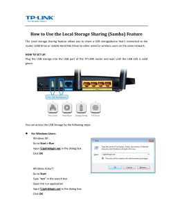


© Copyright 2026