
Document
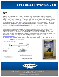
ED 200 Swing Door Operator DORMA ED 200 Swing Door Operator Universal application, simple installation, reliable function As a powerful automatic electro-hydraulic swing door operator, the DORMA ED 200 is suitable for standard and for large and heavy doors. It can be adapted to a wide range of applications and mounting requirements and offers numerous adjustable features. When the permanent open function is activated, the door is held open by a solenoid valve in a way which ensures stability and operational silence. 2 The softline cover can be extended to the full door width providing an optical elegant solution. The DORMA ED 200 – available up to size EN 7 – is also suitable for fire and smoke doors, even with its permanent open function. Double-leaf doors may also be equipped with an integrated door coordinator (ED 200 ESR) which, when viewed from the outside, is concealed behind the cover. As an alternative, we now offer our new VARIO cover (page 16). It can also be installed in emergency exits and escape routes. It can likewise be combined with access control systems. DIN 18 263/T4 Features and benefits 2Two variants (EN 4–6, EN 7), to suit all applications. 2One version for both door directions (left-handed/ right-handed) and mounting positions (hinge (pull) side/opposite hinge (push) side. 2Quick and easy mounting thanks to two auxiliary screws and plugconnected cabling. 2Reliable function even in the case of heavy-use doors and entrances exposed to various weather conditions. 2Optimum adaptability to individual requirements – e.g. in hospitals, homes for the elderly, facilities for the disabled, restaurants, security areas and laboratories. 2Numerous control options. 2Integrated door coordinator for double-leaf doors. 2 Suitable for connection. of tested infrared safety sensors. 3 DORMA ED 200 Technical data and features Applications ED 200 mounted on hinge (pull) side with slide channel Applications Lintel depth (mm) 280 Single- and double-leaf standard doors Single- and double-leaf fire and smoke doors (only with standard arm) Opening width for single-leaf doors (Door leaf width) 275 1) 250 Operator variant EN 4-6 225 with standard arm 1590 mm to 1400 mm with slide channel (mounting on the hinge [pull] side) 880 mm to 1400 mm2) 175 with slide channel (mounting on the opposite hinge [push] side) 1800 mm to 1400 mm 150 with parallel arm 200 125 1680 mm to 1400 mm 100 Operator variant EN 7 with standard arm 1750 mm to 1600 mm with slide channel (mounting on the hinge [pull] side) 1880 mm to 1600 mm2) 50 25 with slide channel (mounting on the opposite hinge [push] side) 1800 mm to 1600 mm with parallel arm Applications 75 0 1680 mm to 1600 mm 880 900 920 940 960 980 1000 1020 1040 1060 1080 1100 Minimum door leaf width (mm) Door leaf Opening width for double-leaf doors1) (for applications with symmetric door leaf widths) 615 alternatively 850 mm Operator variant EN 4-6 with standard arm 1284 mm to 2800 mm with slide channel (mounting on the hinge [pull] side) 1750 mm to 2800 mm2) with slide channel (mounting on the opposite hinge [push] side) 1600 mm to 2800 mm with parallel arm 1360 mm to 2800 mm Operator variant EN 7 with standard arm with slide channel (mounting on the hinge [pull] side) 1284 mm to 3200 mm 1750 mm to 3200 mm2) with slide channel (mounting on the opposite hinge [push] side) 1600 mm to 3200 mm with parallel arm 1360 mm to 2800 mm Door leaf weight, max. 250 kg Lintel depth with standard arm with slide channel (mounting on the hinge [pull] side) –40 mm to 500 mm –20 mm to 280 mm2) with slide channel (mounting on the opposite hinge [push] side) 0 mm with parallel arm 1) 2) 4 –40 mm to 160 mm oor widths beyond the above-mentioned ranges on D demand! Attention! Please consider the minimum door leaf width according to the above diagram. Additionally a special slide channel or a mounting position different from the drawings in this brochure could be required. Special solutions on demand! 30 Technical data of the drive unit Closing force (2 operator types) EN 4 – 6 (adjustable) EN 7 (fixed) Dimensions Height 106 mm Depth 133 mm Width 665 mm Continuous/extended cover for singleand double-leaf door operators Weight per operator One operator variant for mounting on the hinge (pull) and opposite hinge (push) side, and LH (ISO 6) and RH (ISO 5) doors Power consumption, max. Supply voltage X 18 kg x 250 W 230 V, 50/60 Hz Power supply for external accessories with control board A 800 mA at 12/24 V AC; 600 mA at 24 V DC with control board B 1500 mA at 12/24 V AC; 1000 mA at 24 V DC Stabilized power supply (e.g. for smoke detectors) with control board B 100 mA at 24 V DC Class of protection IP 20 TÜV type-approved x Compliant with the Low Voltage Directive and the EMC Directive x Manufactured to ISO 9000 x Adjustable parameters of the driving phase Function programs Opening angle, max. with standard arm 115° with slide channel (mounting on the hinge [pull] side) 90° Control board A Control board B Off x x Automatic x x Permanent open x x with slide channel (mounting on the opposite hinge [push] side) 90° Exit only– x with parallel arm 90° Nurse-bed-function for double-leaf doors (only in combination with special module SM 206) x x Airlock function (only in combination with door reed contact TK) X X Timed airlock function (only in combination with special module SM 208 and door reed contact TK) Adjustable opening time ≥ 1,5 s Adjustable closing time ≥3s Adjustable hold open time 0 s – 30 s Adjustable backcheck x Adjustable delayed action x Adjustable wall blanking for safety sensors x Functions and adjustment possibilities 7 115ϒ 75ϒ 2 3 6 25ϒ 1 Special functions X X Night-/bank function– x Push&Go function (only in combination with Push&Go module) X X Flip-flop-function (only in combination with special module SM 202) X X Door closer function under cut-out conditions x x 5 Prepared for connection of the following accessories 4 1 Adjustable opening speed 2 Adjustable backcheck 1 + 2Adjustable opening time 3 Adjustable closing speed 4 Adjustable delayed action 3 + 4Adjustable closing time 5 Easy manual operation with bypass valve 6 Backcheck range for manual operation 7Adjustable opening angle, adjustable hold open time Standard arm, slide channel, parallel arm x x DORMA IRS-2 infrared safety sensors (mounting on the hinge [pull] and opposite hinge [push] side) x x Door locking device x x Electric strikes (fail-safe/fail-secure principle) x x DORMA SVP emergency exit motor lock with self-locking action – x Access control system (DORMA AutoSwitch) – x Activators (Pushbutton, Radar movement detector ...) x x Radio remote control x x External program switch (integrated 3-position program switch as standard) x x Smoke detectors also with i ntegrated power pack* – x * 1 x lintel-mounted RM-ED or RM when bottom edge of lintel to bottom edge of smoke-sealed ceiling < 1 m In addition: 2 x ceiling-mounted RM when bottom edge of lintel to bottom edge of smoke-sealed ceiling > 1 m xstandard Xoptional 5 DORMA ED 200 for single-leaf doors Mounting on the opposite hinge (push) side with standard arm for LH (ISO 6) and RH (ISO 5) doors (example: RH [ISO 5] door) 665 64 508,5 64 45 5,5 38 1) 24,5 280 315 15 112 106 133 36 62,5 X 50 Mounting on the opposite hinge (push) side with slide channel for LH (ISO 6) and RH (ISO 5) doors (example: RH [ISO 5] door) 62,5 F (not approved for fire and smoke doors) 665 508,5 64 64 123 23 1) 40 30 15 17 12 47 36 106 133 175 598 280 Mounting on the hinge (pull) side with slide channel for LH (ISO 6) and RH (ISO 5) doors (example: RH [ISO 5] door) 665 64 503,5 64 1) 40 47 30 12 17 123 106 133 36 57,5 (not approved for fire and smoke doors) 250 598 615 350 20 Mounting on the hinge (pull) side with parallel arm for LH (ISO 6) and RH (ISO 5) doors (example: RH (ISO 5) door) 665 64 50 90 20 6 350 X A 133 106 60 29 48 53,5 48,5 159,5 106 82 1) 14,5 64 503,5 36 57,5 (not approved for fire and smoke doors) Mounting plates/axle extension 649 629 575 319,5 21 34 66 84,5 100 34 66 84,5 100 8 34 66 84,5 100 13 7 34 66 84,5 100 axle extension (see page 18) *maximum axle extension : 48 mm, maximum closing force: EN 6 maximum door leaf weight: 120 kg 21 1) optional 21 h1 = 21 (Standard) 21 20 h1 – 12,5 Standard arm var. 01 var. 02 var. 03 var. 04* 8,5 Lintel depth X – 40 to 120 mm 80 to 240 mm 240 to 360 mm 360 to 500 mm 74 46,5 Axle extension/spindle extension 280 13 21 30 48 73 95 649 629 575 319,5 20 74 46,5 Lintel depth: 0 mm 8 h1 – 15 15 h1 = 30 (Standard) 13 7 1) optional axle extension (see page 18) Axle extension/spindle extension 280 13 21 30 48 649 629 602,5 575 20 1) h1 – 7 8 h1 = 13 (Standard) 20 Lintel depth: – 20 mm to 280 mm (Attention! Please consider the minimum door leaf width according to the diagram on page 4) 329,5 74 8 12 optional axle extension (see page 18) Axle extension/spindle extension 350 Min. distance X up to 40 mm = 200 mm X up to 100 mm = 260 mm X up to 160 mm = 290 mm Min. 13 21 30 48 649 629 602,5 575 20 329,5 74 ° 90 *For dimension A see drawing on the left h1 = 13 (Standard) 12 8 8 Parallel arm var. 01 var. 02 var. 03 var. 04 h1 +43,5 A* 50 50 80 80 56,5 Lintel depth X – 40 to 0 mm 0 to 40 mm 40 to 100 mm 100 to 160 mm Axle extension/spindle extension 350 13 21 30 48 73 95 7 DORMA ED 200 for double-leaf doors Mounting on the opposite hinge (push) side with standard arm 64 508,5 64 38 5,5 36 36 62,5 F 280 315 15 50 Passive leaf Mounting on the opposite hinge (push) side with slide channel 64 503,5 64 12 47 30 17 36 57,5 (not approved for fire and smoke doors) 586 600 20 280 Passive leaf Mounting on the hinge (pull) side with slide channel 64 503,5 64 12 47 30 17 36 57,5 (not approved for fire and smoke doors) 586 250 600 20 350 Active leaf Mounting on the hinge (pull) side with parallel arm 64 503,5 64 29 48 53,5 36 57,5 (not approved for fire and smoke doors) 50 90 20 8 350 A Active leaf 112 Lintel depth X –40 to 120 mm 80 to 240 mm 240 to 360 mm 360 to 500 mm 1) 45 36 133 X Standard arm var. 01 var. 02 var. 03 var. 04* 1) optional axle extension (see page 18) *maximum axle extension: 48 mm maximum closing force: EN 6 maximum door leaf weight: 120 kg B = min. 1284 mm Active leaf 133 123 Lintel depth: 0 mm 1) optional axle extension (see page 18) 40 1) B = min. 1600 mm Active leaf 133 123 Lintel depth: –20 mm to 280 mm (Attention! Please consider the minimum door leaf width according to the diagram on page 4) 40 1) 1) B = min. 1750 mm optional axle extension (see page 18) Special door widths on demand Passive leaf 48,5 B = min. 1360 mm X 14,5 159,5 60 Passive leaf 133 106 82 Lintel depth X A* Parallel arm – 40 to 0 mm 50 var. 01 0 to 40 mm 50 var. 02 40 to 100 mm 80 var. 03 100 to 160 mm 80 var. 04 *For dimension A see drawing on the left Special door widths on demand 9 DORMA ED 200 for “contraflow traffic” Mounting on the hinge (pull) and opposite hinge (push) side 503,5 64 118 64 250 62 12 64 47 17 36 57,5 (not approved for fire and smoke doors) 598 615 20 The decisive advantage of the double-door “contraflow traffic” lies in the fact that each door leaf controls just one direction, so separating the ingress and egress flows as users enter or leave the building or area. There is also the advantage that 10 passage through the doors takes place immediately because they always open in the walking direction. This application is therefore especially suitable for doors in which there is a constant or occasionally heavy flow of users like the entrances to 350 department stores, leisure facilities and administration buildings, but also for the kitchen entrances of large restaurants and hotels. The two swing door operators operate individually: The drive unit of each operator controls all the parameters, such as opening, closing and hold open times, and also the functions triggered by the safety sensors. 508,5 64 62,5 64 12 64 34 41 36 118 64 1) 1) 15 50 315 280 B Also available with 2 slide channels Hinge (pull) side: Slide channel, pulling Lintel depth: –20 mm to 280 mm (Attention! Please consider the minimum door leaf width according to the diagram on page 4) 1) optional axle extension (see page 18) Lintel depth X –40 to 120 mm 280 to 240 mm 240 to 360 mm 360 to 500 mm Standard arm var. 01 var. 02 var. 03 var. 04* 1) optional axle extension (see page 18) *maximum axle extension: 48 mm maximum closing force: EN maximum door leaf weight: 120 kg 11 DORMA ED 200 Fire and smoke doors F Mounting on the opposite hinge (push) side with standard arm Single-leaf doors for LH (ISO 6) and RH (ISO 5) doors (example: RH (ISO 5) door) 665 64 508,5 106 64 5,5 38 36 62,5 280 315 15 50 Mounting on the opposite hinge (push) side with standard arm (Drawing for ED 200, ED 200 ESR 1/2 and ED 200 ESR) Double-leaf doors 64 508,5 38 5,5 36 64 36 62,5 280 315 15 50 Passive leaf In the case of fire and smoke doors, the ED 200 is always fixed on the opposite hinge (push) side with a standard arm. Such systems are referred to as hold open systems. Compliant with the German guidelines governing hold open systems issued by the German Institute for Civil Engineering DIBt (Berlin), hold open systems must always consist of the 4 following components: 1.Activator (complied with by RM-ED or RM) 12 2.Pushbutton (with “Tür schließen” wording) 3.Power supply and 4.Hold open system (3. and 4. complied with by ED 200). The ED 200 has the approval for application at fire and smoke doors. Please refer to the chart on page 5 for all possible combinations of operators and DORMA smoke detectors. The connection of smoke detectors, supplied by others, is also possible. The number of smoke detectors normally depends on the distance between the bottom edge of the lintel and the bottom edge of the smoke-sealed ceiling. Please see page 14 for number and positioning of smoke detectors. Depending on requirements, individual or several electric strikes can be connected which must operate in accordance with the failsecure principle. In addition, it must be ensured that they are installed in the correct (approved) position. For all components of this system, including the electric strikes, approvals must be obtained in accordance with the German Institute for Civil Engineering (DIBt). Lintel depths of up to 500 mm Lintel depth X –40 to 120 mm 280 to 240 mm 240 to 360 mm 360 to 500 mm Standard arm var. 01 var. 02 var. 03 var. 04 * maximum axle extension: 48 mm maximum closing force: EN 6 maximum door leaf weight: 120 kg * 1) X 1) optional axle extension (see page 18) Fire and smoke doors with lintel depths of up to 500 mm may also be equipped with the ED 200 swing door operator, as it is also approved by the German Institute for Civil Engineering DIBt with standard arm variant 04. 36 F Approval Certification B Active leaf The ED 200 is always mounted on the opposite hinge (push) side of single- and doubleleaf fire and smoke doors with standard arm. The two operators, which are concealed behind the continuous cover, operate according to the master-slave principle: The active leaf operator controls all the parameters (e.g. hold open time) and also the functions actuated by the safety sensors (IRS-2). Both operators are fed internally by an external power supply. In the event of a fire, the door can be activated by the DORMA RM-ED and RM smoke detectors (see page 5, 14/15). The connection of smoke detectors supplied by others is also possible. Door coordinator According to EN 1158, a double-leaf swing door operator must be equipped with a mechanical door coordinator. The purpose of the door coordinator is to ensure that even under cut-out conditions the two door leaves close in a correct sequence (passive leaf before active leaf), so producing a tight barrier seal. With two integrated versions and the external version, DORMA offers three door coordinators for the ED 200 (see page 16). The DORMA ED 200 auto matic swing door operator is approved in Germany by the MPA (State Material Testing Authority) NRW Dortmund in accordance with DIN 18263, Part 4, and is subject to third-party quality assurance X verification. In combination with the DORMA RMZ 2 smoke detector with integrated power pack and DORMA smoke detectors, it is approved by the German Institute for Civil Engineering DIBt (Berlin) for use on single- and doubleleaf fire and smoke doors provided that this is allowed by the approval certificate for the door concerned. The DORMA ED 200 has been tested and approved as hold open system for single- and double-leaf doors in accordance with the German guidelines governing hold open systems. 13 DORMA ED 200 Smoke detectors for fire and smoke doors Number and positioning of smoke detectors 230 V max. 0,1 m 230 V ≤ 3m NO Does the door width exceed 3,0 m? 2 Ceiling-mounted detectors1) 2 Ceiling-mounted detectors1) 0,6 – 2,4 m ≤1m 0,6 – 2,4 m ≤1m NO YES 230 V 230 V >3m >3m 2 Ceiling-mounted detectors + 1 Lintel-mounted detector1) 0,6 – 2, 4m >1m Does the distance between the bottom edge of the ceiling and the bottom edge of the lintel exceed 1,0 m on one or on both side/s of the door? 2 Ceiling-mounted detectors + 1 Lintel-mounted detector1) 0,6 – 2, 4m 230 V 1) max. 0,1 m YES >1m 230 V For opening widths beyond 4 m further smoke detectors are required. For application at fire and smoke doors: RM-ED smoke detector 14 RM smoke detector ≤1m 1 Lintel-mounted detector ≤1m 1 Lintel-mounted detector DORMA RM-ED lintel-mounted smoke detector 30 B 45 34 378 The optical DORMA RMED smoke detector can be installed as ED 200 lintelmounted smoke detector. 12/25 Bolzen A 357,5 Dimensions: 34 x 378 x 30 mm DORMA RM lintel- and ceiling mounted smoke detector 53 ∅ 100 32 45 170 Ø 4,5 As universal optical smoke detector, the DORMA RM is suitable for lintel- and ceiling-mounting. It is connected to a DORMA RM-ED smoke detector or a DORMA ED 200 swing door operator. It is ready for connection of further DORMA RM smoke detectors, a manual release pushbutton and a light indicator. Dimensions: 53 x 195 x 52 mm DORMA RM Red/green light indicator, test input for functional test, power supply: 24 V DC, power consumption: 25 mA, maximum load current: max. 2 A at 60 V AC. E 6/C 0 (silver-coloured) Order No. 64820001 RAL 9016 (white) Order No. 64820011 Special colour Order No. 64820009 E 6/C 0 (silver-coloured) Order No. 64840001 RAL 9016 (white) Order No. 64840011 Special colour Order No. 64840009 DORMA RM-N ceiling-mounted smoke detector 52 195 DORMA RM-ED Red/green light indicator, test input for functional test, power supply: 24 V DC, power consumption: 75 mA, maximum load current: max. 2 A at 60 V AC. RM-N The DORMA RM-N serial smoke detector detects smouldering fires as well as open fires with smoke emission at an early stage. It is designed for application as second or third detector for hold-open devices and in combination with RMZ-ED and RM detectors. Operating voltage 24 V DC White Order No. 64830000 F Approval Certification The smoke detectors DORMA RM-ED and RM are approved by the German Institute for Civil Engineering DIBt (Berlin) and are subject to third-party quality assurance verification. DORMA HT manual release pushbutton for hold-open devices 80 12,5 Tür schliessen flush-mounting Order No. 19144601175 80 This pushbutton is designed to release hold-open devices by hand. Where hold-open devices with free-swing door closers are applied at fire and smoke doors, the installation of a manual release pushbutton is compulsory DORMA HT single-pole changeover contact, standard frame, red label with white inscription reading “Tür schliessen” according to the guidelines of the German Institute for Civil Engineering (DIBt), Berlin. surface-mounted box for DORMA HT Order No. 05158533332 (not displayed) 15 Door coordinator for double-leaf fire and smoke doors DORMA ED 200 ED 200 ESR with integrated door coordinator The ED 200 ESR combines operational reliability and excellent optical characte ristics with a minimum of installation and maintenance costs. The door coordinator is installed in the factory and located behind the continuous cover of the doubleleaf door system and no additional slide channels and pivot bearings are required on the hinge side. Thanks to the fact that the door coordinator is installed in the factory, no additional installation work is necessary compared to the stand-alone operator, reducing both installation time and installation costs to a minimum. The hydraulic system works in a closed circuit, which does not require readjustment and renders the system maintenance-free. Furthermore all arm components of the ED 200 system can still be used. The ED 200 ESR is supplied as a closed unit so that you only need a single order number and no extensive search in the price list and the planning documents is required. Of course the ED 200 ESR is suitable for installation at fire and smoke doors and its integrated door coordinator ensures – also in this combination – a proper closing behaviour of the door under cut-out conditions. When applied at fire and smoke doors, the whole system has to be planned as hold-open device (see page 14/15). ED 200 ESR 1⁄2 for partially automated double-leaf doors The low-priced application for double-leaf doors (fire and smoke doors) In general both door leaves of a double-leaf door are automated, however, for pedestrian traffic it is sufficient to automate only one door leaf. This is where the ED 200 ESR 1/2 comes into play as it is the low-price application that automates only one of the two door leaves. While the active leaf is opened full-automatically, the passive leaf can be operated manually and has the function of a door closer. Thanks to its integrated hold-open device, both door leaves can be set to Permanent Open while no further components are required. Of course the ED 200 ESR 1/2 is suitable for application at fire and smoke doors and ensures, due to its integrated door coordinator – also in this combination – the safe closing behaviour of the door under cut-out conditions. When applied at fire and smoke doors, the whole system has to be planned as hold-open device (see page 14/15). DORMA ED 200 with VARIO cover: Always the suitable operator in stock With the new ED 200, we now offer a ready-for-installation swing door operator for double-leaf doors that is available within a short period of time. A further benefit of this new system is its adaptability to any width 1 1. Standard cover 2. Cover for cutting edge 3. VARIO cover 16 you may desire to cover. It has a variable centrepiece between the two equally sized standard operator parts consisting of the cover and the base plate. Thanks to the innovative VARIO cover, you can cut the operator cover to the desired length on the building site. All 2 parts are connected while covers hide the cutting edges. The VARIO cover can also be combined with the wellestablished ESR integrated door coordinator and the ESR 1/2 version. 3 2 1 DORMA ED 200 Partially automated double-leaf doors ED 200 ESR 1⁄2 behind continuous cover 15 280 280 Passive leaf/opposite hinge (push) side 15 Active leaf/opposite hinge (push) side ED 200 with TS 93-B door closer without continuous cover 142 160 428 280 81 143 Passive leaf/opposite hinge (push) side Active leaf/opposite hinge (push) side 30 30 ED 200 with ITS 96-GSR-EMF 70 ITS 96 GSR/GSR-EMF 96,5 30 31 ITS GSR/Pivot block 68 141 106 90 133 48,5 69 70 280 40 Passive leaf Active leaf 17 DORMA ED 200 Arm versions and accessories Arm versions 82 133 48,5 106 133 14,5 133 X X DORMA offers a competitive range of arms and axle extensions in order to cope with all door versions and ways of mounting. Apart from a standard arm, also a slide channel and a parallel arm are available. The standard arm is espe cially suitable to transfer the maximum force onto the door leaf and is applied where the system is mounted on the opposite hinge side (push side). The joint can be opened easily what facilitates the installation considerably. The standard arm pushes the door in opening direction and offers the ED 200 operator enough power for installation at fire and smoke doors. The slide channel is suitable for installation on the hinge side (pull side) and on the opposite hinge side (push side). Apart from its appealing design, it offers the benefit that it can also pull the door. However, due to its force progression, the slide channel is not suitable for application at fire and smoke doors. The parallel arm is adequate where the operator is installed on the hinge side (pull side) and when small door leaves have to be automated. Furthermore lintel depths of up to 160 mm can be handled. All these arm versions are supplied with an axle extension. When required, additional axle extensions are available as an option in order to compensate differentials in height. Optional axle extension for variable height increase of ED 200 swing door operators with standard arm ED 200 D Y 18 Y with parallel arm D Y H with slide channel ED 200 Height H mm 13* 21* 30* 48* 73* 95* ....... D mm 6 14 23 41 66 88 .....Y mm 30 38 47 65 90 112 Order No. 19425251150 19425252150 19425253150 19425254150 19425256150 19425255150 13* 21* 30* 48* 14 22 31 49 47 55 64 82 19433201150 19433202150 19433203150 19433204150 53,5 61,5 70,5 88,5 113,5 135,5 19425204150 19425201150 19425202150 19425203150 19425206150 19425205150 13* 21* 30* 48* 73* 95* * Part of the scope of delivery DORMA ED 200 Wiring diagrams Connections ED 200 for single-leaf doors 01Feeder 2a Emergency pushbutton Function: Emergency off 4 x 0,8 mm 16 13 19 4 x 0,25 mm 05Electronic PGS external program switch 4 x 0,8 mm 04Mechanical PGS external program switch 2 x 0,8 mm NYM 3 x 1,5 mm2 ED 200 4 x 0,8 mm 4 x 0,8 mm 8 x 0,8 mm 2 x 0,8 mm 03Two-pole-and-earth socket 18 6 x 0,8 mm 4 x 0,25 mm 4 x 0,8 mm 2 x 0,8 mm 17 2 x 0,8 mm 2bEmergency pushbutton Function: Emergency stop 3 2a 9 2b 06Pushbutton 7 8 10 11 5 4 12 10 A 07Pushbutton, inside 1 08Pushbutton, outside L1 N PE 09Door locking device 10Radar, inside 11Radar, outside 12Key switch ED 200 for double-leaf doors 13ED 200 14ED 200 with continuous cover 4 x 0,8 mm 17 16 4 x 0,8 mm 2 x 0,8 mm 2 x 0,8 mm NYM 3 x 1,5 mm2 ED 200 2 x 0,8 mm 4 x 0,8 mm 4 x 0,25 mm 4 x 0,25 mm 2 x 0,8 mm 9 2 x 0,8 mm 9 14 18RM smoke detector, hinge (pull) side 4 x 0,8 mm 17RM smoke detector, opposite hinge (push) side 8 x 0,8 mm 16RM-ED smoke detector 3 2a 19 2b 7 8 10 11 5 4 12 10 A 1 L1 N PE ED 200 for “contraflow traffic” je 2 x 0,8 2 x 0,8 mm 4 x 0,25 mm 2 x 0,8 mm 2 x 0,8 mm 2 x 0,8 mm 8 x 0,8 mm 4 x 0,25 mm 9 4 x 0,8 mm 3 x 1,5 mm ED 200 8 x 0,8 mm 15 2 x 0,8 mm 19Manual release switch, with “Tür schließen” wording 18 6 x 0,8 mm 2 x 0,8 mm 4 x 0,8 mm 15ED 200 for “contraflow traffic” 3 12 4 5 10 6 2b 6 10 5 4 12 2a 10 A 1 L1 N PE 19 DORMA ED 200 Example combinations Suitably equipped for the requirements of handicapped people: The rest room for handicapped people Public buildings must have rest rooms that are tailored to the requirements of handicapped people. However, special care must be devoted to the needs of wheelchair drivers. A corresponding room layout is as important as the availability of sufficient space. The accessibility with the aid of an automatic door operator is likewise important for handicapped people and can, among others, be realized with a special key switch, which triggers an opening pulse. In case there is a person inside the rest room, the door can be locked via pushbutton (locking via electric strike) while a red-green display indicates the door status. Emergency sensors may be integrated into the door system if desired. As you see, DORMA takes care that every special requirement is considered. 20 ED 200 for rest rooms for the disabled 200 x 125 x 77 mm 12 2 6 4 x 0,8 mm 2 x 0,8 mm 2 x 0,8 mm 2 x 0,8 mm 4 x 0,8 mm 4 ED 200 3 x 1,5 mm 6 x 0,8 mm 2 x 0,8 mm 2 x 0,8 mm 3 x 1,5 mm Connections 11Feeder: 230 V, 50/60 Hz 12Two-pole-and-earth socket (by others) 13Junction box (by others) 14DORMA ED 200 15Fail-safe lock, 24 V DC 16Alarm siren with signal lamp (red) 17Palm pushbutton with disabled symbol 18Concealed/flush-mounted emergency pushbutton, located behind emergency break glass 19Concealed/flush-mounted signal lamp (red) 10Concealed/flush-mounted palm switch, with “open/ locked” wording 11Flush-mounted pull switch, for emergency opening 12Auxiliary drive unit, housed in external cover 9 3 10 A Auf Verriegelt 5 7 8 10 L1 N PE 1 inside outside 11 Application of the ED 200 swing door operator in smoke and heat ventilation systems Smoke and heat ventilation systems are applied in preventing fire protection with the following objectives: 2To evacuate smoke and heat in the event of a fire. 2To keep emergency exits and escape routes free from smoke and gas. 2To create a smoke-free layer and to facilitate fire fighting. 2They can also be used for ventilation purposes (air supply/air withdrawal). 2To open air outlets like windows and dome lights in the event of a fire. 2Automatic and remote activation. 2To supply and to withdraw air. A smoke and heat ventilation system consists of a smoke outlet, fire detectors, a control unit and an air supply opening. In smoke and heat ventilation systems, the ED 200 is mounted to doors serving as air supply openings. These doors are designed to create a balance between the air inflow and the outflow of gas in the roof area of the building (e. g. windows). The following system solutions are approved as air supply openings: 1.ED 200 with USV emergency power supply unit 2.ED 200 Inverse (see page 22 for “Mechanical opening under cut-out conditions”) ED 200 with USV emergency power supply unit The drawing shows an example for an air supply opening. In contrast to smoke and heat ventilation systems, equipped with the ED 200 Inverse, the ED 200 operates in daily use (without activation of the smoke and heat ventilation system) as properly and reliable as usually, which allows also heavy usage of the door. On activation of the smoke and heat ventilation system (floating opening contact), the ED 200 opens the door which remains open until the smoke and heat ventilation system has been reset. In order to ensure this function for a certain period of time even under cut-out conditions, the ED 200 is equipped with an emergency power supply unit integrated in its 230 V-wiring. In addition to the emergency power supply unit, the system is equipped with a power overload protection. If the power consumption falls Example Door status of ED 200 + SM 202 special module smoke and heat ventilation system radar pushbutton electric strike plate NYM 3 x 1,5 mm2 Feeder 230 V/AC USV emergency power supply unit below an admissible value, the emergency power supply unit switches to emergency mode within 20 ms. The following components must be installed when using the ED 200 in the air supply opening of a heat and smoke ventilation system 2E mergency power supply unit MT 700 USV 2 Special module SM 202 21 DORMA ED 200 Example combinations ED 200 Inverse (mechanical opening under cut-out conditions) The ED 200 Inverse is especially suitable for large buildings such as airports, theatres or congress centres. In the event of an emergency, the ED 200 activates doors even under cut-out conditions in order to make escape routes available. For this application, the operating principle of the ED 200 is reversed: The operator actuates the door to open by using the energy stored in the integrated door closer, then the door is closed by motor power. The opening width must be limited by an external door stop. In contrast to the ED 200 with emergency power supply unit, the ED 200 Inverse cannot be connected to a radar motion detector; it is activated via push button. The ED 200 Inverse can perform 3 different operating principles. System solution 1 Timed closing action. The ED 200 Inverse is activated via pushbutton and opens the door for an adjustable hold open time from 0 to 100 s. On expiry of this period, the door is closed automatically. The following components are required for this system solution: 2Operator variant ED 200 Inverse 2Special module SM 202 2Door locking device TV 200 2Pushbutton for activation System solution 2 Flip-flop-function (positively activated closing action) Pressing the pushbutton institutes the ED 200 to open the door. The door remains open until the door closing is activated by pressing the pushbutton again. The following components are required for this system solution: 2Operator variant ED 200 Inverse 2Special module SM 202 2Door locking device TV 200 2Pushbutton for activation TV 200 electrical locking device 22 NYM 3 x 1,5 mm2 Feeder 230 V ~ ED 200 + special drive unit TV 2 x 0,8 System solution 3 DORMA TMS door management system (for emergency exits and escape routes). The ED 200 is approved for installation in emergency exits and escape routes when controlled by the DORMA TMS door management system. In the event of an emergency, the door terminal institutes the door to open. The following components are required for this system solution: 2Operator variant ED 200 Inverse 2Special module SM 202 2Door locking device TV-DCW 2Door terminal TL-TMS TL-TMS door terminal 2 x 0,8 Summary The ED 200 Inverse can be instituted to open a door via: 2Pushbutton 2Power failure 2Emergency pushbutton 2Smoke detector 2A higher-level fire detection system or hazard warning system 2Activation from central control position SM 202 special module Emergency exit control system The door is normally locked (DORMA TV 200, TV 500). Operation of the emergency pushbutton in the DORMA TL door terminal causes the locking mechanism to be de-energized and released, and also the deadbolt and latch of the DORMA SVP 200 emergency exit motor lock to be withdrawn and enabled respectively. At the same time the system emits an alarm and the DORMA ED 200 receives an opening signal. Authorized users may unlock the door with the DORMA TL key switch/button or via DORMA access control systems. If the DORMA RM smoke detector responds, the DORMA TV electrical locking device is unlocked, the DORMA SVP 2000 emergency exit motor lock with self-locking action is locked and the DORMA ED 200 is de-energized. These actions ensure that the fire protection characteristics of the door are maintained. If activated from a central control position, the TV electrical locking device and the SVP 2000 emergency exit motor lock are unlocked and the ED 200 opens the door. MPA (German Material Testing Authority) VdS (insurance) approval certificates for use in emergency exits and escape routes have been issued for this system. RM BMA DCW ® Junction box SVP-S2X DCW ® I/O DCW ® Radar Feeder 230 V ~ ED 200 KÜ The following components are required: 2DORMA ED 200 swing door operator 2TL-G TMS door terminal with TL-S TMS control board 2TV 200, TV 200 DCW electrical locking device 2SVP 2000 emergency exit motor lock with selflocking action 2SVP-S DCW motor lock control module 2SVP-A … motor lock cable 2Flush-mounted cable loop KÜ ST 32 DCW key button 2DCW junction box 2I/O DCW module Concealed/ flush-mounted socket TV DCW ® Feeder 230 V ~ TL TMS SVP 2000 SVP-A ST 32 DCW ® outside Insurance lock When closed, the door is locked by the DORMA SVP 2000 emergency exit motor lock with self-locking action (insurance lock). The door can be opened and closed from the inside at any time, with unlocking action of the DORMA SVP 2000 and the delayed activation of the DORMA ED 200 being initiated either manually or by active detectors as required. Activation control from a central position is also possible. Authorized users may be granted access from the outside. Once the door is closed, the insurance lock is reinstated fully automatically as the DORMA SVP 2000 automatically throws the bolt after each closing cycle. The DORMA SVP-S22 motor lock control module is installed under the extended cover of the ED 200 for activation control of the DORMA SVP 2000. The following components are required: 2ED 200 swing door operator 2SVP 2000 emergency exit motor lock with selflocking action 2SVP-S22 DCW motor lock control module 2SM 24 special module for stabilized power supply 2SVP-A … motor lock cable 2Concealed/flush-mounted cable loop KÜ 2Activator ED 200 SVP-S22-DCW ® SM24 NYM 3 x 1,5 mm2 Feeder 230 V ~ 2 x 0,8 KÜ SVP 2000 SVP-A ST 23 DORMA ED 200 DORMA IRS-2 infrared safety sensor DORMA IRS-2 Safety Reversal STOP Rever sing this side of the door, the door is reopened automatically due to a new activating impulse given by the safety sensor. In case that the safety sensor on the hinge (pull) side is activated, the automatic opening action of the door is stopped in order to avoid collisions with objects in the scanning range of the IRS-2 safety sensor. The technical principle of the safety sensor ensures that people and objects Benefits and features 24 Number of integrated safety sensors Length of safety sensor IRS-2-33 1 1330 mm IRS-2-70 1 1700 mm IRS-2-90 2 1900 mm IRS-2-120/2 2 1200 mm IRS-2-120/3 3 1200 mm 37 0 1m 1m 30° 2m m Cross section m 00 25 IRS-2 infrared safety sensor variants Scanning range 2m x. 2Ideal activating sensor for confined situations due to its small scanning range 2May serve as travelling opening protection for swing doors 2Monitoring of crushingand shearing edges recommends to select the longest-possible IRS-2 safety sensor variant with a maximum number of integrated infrared sensors as the scanning range grows in line with the number of infrared sensors. This ensures the maximum safety of the swing door. ma 2Available in the following lengths: 330, 700, 900 and 1200 mm 2Suitable for LH (ISO 6) and RH (ISO 5) doors 2Mounting on the hinge (pull) and opposite hinge (push) side 2Suitable as opening activator for automatic doors are detected at the same time. The scanning range of the IRS-2 is adjustable and infrared light is used to safeguard the driving phase of the door. As an active infrared sensor, the IRS-2 detects all static and moving objects, e. g. items or people, within its scanning range. The IRS-2 is available in different lengths and with a variable number of infrared sensors. Depending on the door width, DORMA 42 The DORMA IRS-2 safety sensor is a monitoring module designed to safe guard the sweep range of automatic swing doors. It can be mounted travelling on the hinge (pull) and opposite hinge (push) side of the door. If mounted on the opposite hinge (push) side, the DORMA IRS-2 safety sensor acts as an activator to open the door in the close range of the door. As soon as an object is located on IRS-2 mounting dimensions Mounting on the opposite hinge (push) side with slide channel 85 44 91 Mounting on the hinge (pull) side with slide channel 85 Mounting on the opposite hinge (push) side with standard arm 38 38 23,5 38 30 30 4,2 Electronic control unit Push&Go The ED 200 is also available with the electronic control unit Push&Go, which can easily be retrofitted as an accessory. Just push slightly and the door leaf opens automatically, thus even heavy doors can be operated without any effort. Inhibitions not least older people might have when it comes to modern technology are being removed. In contrast to radar or infrared-controlled door systems, the comfort version ensures that heavy-used doors and entrances are not opened unnecessarily. Push&Go is the appropriate alternative for locations with insufficient space for radar or pushbutton activation. Where fire doors are retrofitted with Push&Go, the fail-safe lock need not be exchanged. An additional incremental encoder ensures that the Push&Go system can be activated from any opening angle. Furthermore, the sensitivity of the system is adjustable in 15 levels. If the door hits an obstacle during its closing action, it will be reopened immedia tely. As no additional wiring is required, Push&Go is the economical alternative to a radar-controlled system. Application and benefits 2In contrast to radar or infrared-operated door systems, the ED 200 Push&Go prevents heavyused doors from being opened unnecessarily 2Ideal solution for locations with insufficient space for radar or pushbutton activation 2Even heavy doors can be opened manually with the support of Push&Go 2It minimizes the inhibition thresholds of older people 2Activation from any opening angle 2The ED 200 (with control board A and B) can easily be retrofitted with Push&Go 2Adjustable sensitivity (15 levels) 2Safety function: the opening action is reversed as soon as the door hits an obstacle 115ϒ 15 x 0,7ϒ = 10,5ϒ 25 DORMA ED 200 System accessories Program switch When combining the system with a program switch out of the DORMA accessory range, the automatic door system even meets individual requirements and offers easy handling. These program switches are available in various designs have been conceived for all kinds of demands. Furthermore they offer various options, from a mechanical to a full-electronic version alternatively also lockable via Euro profile half-cylinder or in a full-electronic way via code. 2U p to 4 different functions: Off, Automatic, Exit Only, Permanent Open 2 Electronic program switches in System 55 design to cope with the highest aesthetic demands 30 PG-D1 program switch 4-position, aluminium, white, for control unit A and B, flush-mounted, 80 x 80 mm, Gira S-Color UP = 7,5 AP = 47,5 31 PG-D1 46 80 30 Order No. 19135404150 80 Mounting position for turn switch PG-D3 program switch 4-position, lockable, aluminium, white, control unit B, flush-mounted, 80 x 80 mm, Gira S-Color UP = 7,5 AP = 47,5 36 PG-D3 80 46 30 80 26 Mounting position for turn switch Order No. 19135604150 PG-D4 PG-D4 program switch 4-position, lockable via Euro profile half-cylinder, white, flush-mounting, 105 x 80 x 65 mm, box for surface-mounting: 19142201170 97 105 65 Order No. 19141801170 80 Flush-mounting box 97x75x65 PG-D4 box for surface mounting for PG-D4 for mechanical program switch, 100 x 80 x 65 mm standard frame, white 83,5 100 Thread M3 19 PUSH OUT Order No. 19142201170 15 15 19 21,5 77 PUSH OUT 65 EPS-D 80 13 3 4 80 R 30 1 2 10 EPS-D full-electronic program switch in System 55 design, 4-position, lockable via code or additional TL-ST S55 key switch, membrane keypad, aluminium coloured, white, flush-mounted, 80 x 80 mm Order No. 16557001150 27 DORMA ED 200 System accessories Pushbuttons Pushbutton 12,5 80 Pushbutton Single-pole changeover contact, standard frame, white, flush-mounting, System 55 Order No. 19144701170 80 Key switch 19 9 l 59 75 75 50 60 Flush-mounting version 45 17 KT 3-1 surface mounting Order No. 05054631332 19 9 l 59 75 KT 3-1 Flush-/Surface 75 mounting 10 50 60 Flush-mounting version 40 9 10 Key switch KT 3-1 1 NO contact, with Euro 45 9 profile17half-cylinder (can be replaced by any half-cylinder of a master-key system), you can only withdraw the key 10 10 when it is in zero40position, aluminium, PG 13,5 metal, 75 x 75 x 60 mm Surface-mounting version KT 3-1 flush-mounting Order No. 05054531332 PG 13,5 Surface-mounting version KT 8 Flush-/Surface mounting Key switch KT 8 Lettering “Auf, Zu”, 2 NO contacts, with Euro profile half-cylinder can be replaced by any half-cylinder of a master-key system), you can only withdraw the key when it is in zero position, aluminium, metal, 75 x 75 x 60 mm KT 8 flush-mounting Order No. 05054831332 KT 8 surface mounting Order No. 05054931332 Large-sized pushbutton (elbow) 30 304 254 274 6,5 80 Large-sized pushbutton (elbow) flush-mounting/surfacemounting, electrical, silver anodic coating CO, 304 x 80 mm Order No. 90410015 28 40 57 20 40 Large-sized pushbutton (elbow) Large-sized pushbutton (elbow) surface-mounting, extra-flat design, synthetic material, grey, 209 x 79 x 17 mm 209 169 59,5 40 17 79 Order No. 05080231332 4,8 Large-sized pushbuttons 224 Large-sized pushbutton with box for flush-mounting, without switch pad, incl. switch, 224 x 82 mm Order No. 05095531332 82 44 Surface-mounted design 11 71 224 39,5 82 Flush-mounted design Large-sized pushbutton with box for surface-mounting, without switch pad, incl. 2 switches, paint sprayed for aluminium effect, 224 x 82 x 44 mm Order No. 05095231332 Switch pad aluminium, suitable for flush-/surface-mounting, 214 x 70 mm Order No. 05095431332 Switch pad aluminium, suitable for flush-/surface-mounting, 214 x 70 mm, with inscription reading “Tür auf” Order No. 05095331332 CT 4/1 code keypad as control for locking devices (keypad and electronic module have to be combined) The code keypad does not require optional software for simple access authorizations. The metal keypad is waterproof and protected against manipulation thus it is also suitable for installation on the outside of a building. The four- or six-digit code can be changed at the keypad via Plug & Play. The respective control unit is installed in the protected area and can be connected to all DORMA operators. Surface-mounting, 230 V/50 Hz, 1.5 V A, 1 x UM potentialfree relay contact 8 A, 250 V, connections: max. 2.5 mm, 75 x 75 x 11.5 mm. MTB 4/1 metal keypad to enter the activation code (to open the door) and for programming purposes, surface-mounting, 75 x 75 x 11.5 mm Order No. 05079331332 EB 4/1 Electronic module, incl. 2 m connection cable, plastic cover, black, surfacemounting Order No. 05063431332 29 DORMA ED 200 System accessoires Radio transmitters and transponders Radio remote control system The RC-R radio receiver can be combined with all DORMA operators. Apart from the handy RC-T HandHeld radio remote control, also large-sized pushbuttons are available. Thanks to its individual code, the system can also be applied as a simple access control system. This is realized by storing the code of the radio remote control in the radio receiver via Plug&Play and allows you to allocate different access authorizations. Furthermore this system is especially suitable for upgrades as no wiring for the pushbuttons is required. Coverage: up to 20 m. DORMA RC-R Receiver module including adaptor for installation in ED 200, CD 400, CD 80 and PORTEO 24 V DC, 1 channel, self-learning – also for several remote controls, 24 V DC, max 100 mA, frequency: 433.92 MHz Order No. 16562301170 DORMA RC-T Large-sized pushbutton with integrated radio transmitter, small pushbutton and RC-T radio remote control including battery (product life: approx. 1 year with 60 activations/day), without switch pad, 2 channels, 433.92 MHz, with box for surface-mounting 224 x 82 x 44 mm Order No. 16562201175 Switch pad, aluminium, suitable for flush-/surface-mounting, 214 x 70 mm Order No. 05095431332 DORMA RC-T Large-sized pushbuttons DORMA RC-T HandHeld Hand-held transmitter Switch pad with inscription reading “Tür auf”, aluminium, suitable for flush-/surface-mounting, 214 x 70 mm Order No. 05095331332 DORMA RC-T HandHeld hand-held transmitter, incl. battery (product life: approx. 1 year with 60 activations/day), 4 buttons that can be assigned individually, 2 channels, frequency: 433.92 MHz, plastic, black Order No. 1656210117 DORMA AutoSwitch transponder The active transponder system: This system automatically sends a pulse to the control unit when entering the detection range (which amounts to approx. 2.5 m) and is especially suitable for areas where a manual operation has to be excluded. Thanks to its coverage, it is the adequate access control system for doors used by wheelchair drivers. DORMA AutoSwitch Receiver/control unit, surface-mounting, white Order No. 16571101175 Programming-(Transponder-) key, yellow Order No. 16571201175 Standard-(Transponder-) key, blue Order No. 16571301175 30 Radar motion detectors Radar motion detectors detect approaching people at an early stage and emit an activation (opening) signal for the door operator. Radar motion detectors only respond to movements. Thanks to their various adjustment options, also difficult installations can be realised. Radar motion detectors with direction recognition Eagle 1 Direction recognition, black Order No. 16503101170 Eagle black Eagle white Eagle silver 100 120 3 mm 80 34 26 50 8 mm Cable entry 50 silver Order No. 16503102170 Merkur Cross traffic suppression with direction recognition, black Order No. 16532201170 60 175 white Order No. 16503103170 Merkur 168 57 21 8 150 31 System accessoires DORMA ED 200 Active infrared safety sensors IRS-2 active infrared safety sensor IRS-2-33 with 1 sensor, length: 330 mm Power supply: 24 V DC, power consumption: 100 Maximum load current: 0.2 A at 48 V DC, Installation height: min. 0.5 m / max. 2.5 m IRS-2-70 with 1 sensor, length: 700 mm Power supply: 24 V DC, power consumption: 100 Maximum load current: 0.2 A at 48 V DC, Installation height: min. 0.5 m / max. 2.5 m IRS-2-90 with 2 sensors, length: 900 mm Power supply: 24 V DC, power consumption: 200 Maximum load current: 0.2 A at 48 V DC, Installation height: min. 0.5 m / max. 2.5 m IRS-2-120/2 with 2 sensors, length: 1200 mm Power supply: 24 V DC, power consumption: 200 Maximum load current: 0.2 A at 48 V DC, Installation height: min. 0.5 m / max. 2.5 m IRS-2-120/3 with 3 sensors, length: 1200 mm Power supply: 24 V DC, power consumption: 300 Maximum load current: 0.2 A at 48 V DC, Installation height: min. 0.5 m / max. 2.5 m Colour Order No. mA, silver (E 6/C O) (traffic white) RAL 9016 further RAL 16521701150 16521704150 16521705150 mA, silver (E 6/C O) (traffic white) RAL 9016 further RAL 16521706150 16521709150 16521710150 mA, silver (E 6/C O) (traffic white) RAL 9016 further RAL 16521711150 16521714150 16521715150 mA, silver (E 6/C O) (traffic white) RAL 9016 further RAL 16521716150 16521719150 16521720150 mA, silver (E 6/C O) (traffic white) RAL 9016 further RAL 16521721150 16521724150 16521725150 IRS-2 safety sensors 42 23,6 Cable entry = 165 8 30 32 L 30 38 4,2 Power transit device and cable loops Power transit device type 10305 5 Order No. 05045231332 5,3 41 58 5,3 5 Power transit device Type 10305 two-pole, to transfer electric current from the door frame to the door leaf while the door is closed. 4 71 17 13 Cable loops KÜ 300 cable loop Flexible metal loop for protection of cables between door and door frame, max. cable diameter: 5 mm, Length: 300 mm 300 Order No. 05045331332 10 30 5 KÜ 300/600 Order No. 05101933332 4,2 20,5 KÜ 600 cable loop Flexible metal loop for protection of cables between door and door frame, max. cable diameter: 5 mm, Length: 600 mm 30 Robust stainless steel spiral to protect flexible cables with a diameter of up to 8 mm between movable elements. A B C D KS 155/370 Spring secured by bending the shim 16 0,5 155 A-B Spring loose, not yet secured C-D KS 155 cable loop Cable spiral for door hinges of up to 18 mm, to cover opening angles of up to 110°, variable length: 155 mm, Installation dimensions (W x H x D): approx. 17 x 255 x 15 mm Order No. 15817000 KS 370 cable loop Cable spiral for door hinges of up to 36 mm, to cover opening angles of up to 180°, variable length: 370 mm, Installation dimensions (W x H x D): approx. 17 x 470 x 15 mm Order No. 15819000 Robust stainless steel spiral with recess box for flexible connection cables, for cables with a diameter of up to 8 mm. Ensuring a pinch-free and sabotage-proof connection between the leaf and frame of doors and windows. KÜ 260/480 As linking element between the door leaf and the door frame, the cable loop is of special importance. Like all other DORMA products, these cable loops offer solidity and long product life. Therefore DORMA cable loops have an especially robust metal spiral, which ensures, together with the recess box, the optimum protection of the contained flexible connection cables. KÜ 260 cable loop for door hinges of up to 18 mm, to cover opening angles of up to 110°, variable length: 155 mm, installation dimensions of recess box (W x H x D): approx. 24 x 260 x 17 mm Order No. 15811000 KÜ 480 cable loop for door hinges of up to 36 mm, to cover opening angles of up to 180°, variable length: 370 mm, installation dimensions of recess box (W x H x D): approx. 24 x 480 x 17 mm Order No. 15813000 33 System accessoires DORMA ED 200 KÜ-CD cable loop for door-leaf mounted DORMA swing door operators Junction box (1) for cable loop (internal diameter: 12 mm or 200 mm), white, including accessories (2) 3 4 5 Order No. 5163333332 1 cable loop (3) 600 mm, internal diameter: 12 mm, silver Order No. 5163433332 2 5 2 cable loop (4) 600 mm, internal diameter: 20 mm, silver, incl. fixing elements Order No. 5163533332 The DORMA KÜ-CD cable loop offers the ideal solution for the door leaf fixing options of the CD operator. The combination of – Junction box (1) – Junction box accessories (2) – Cable loop (inner diameter 12 mm) (3) – Cable loop (inner diameter 20 mm) (4) – Adapter-unit (5) enables elegant concealment of all the requisite cabling connecting the operator to the supply. 34 Adaptor unit (5) to conceal the cabling on its way into the operator, combinable with both cable loops silver Order No. 5163133332 RAL 9016 (traffic white) Order No. 5163233332 Further accessories Red-green display The red-green display indicated the status of the door system. The extravagant, semicircular designer signal lamp is made of acryl, manufactured according to the latest LED technology and has a high-grade LED display (24 V, brilliancy according to DIN VDE (German association of engineers) 0834, part 1). The light signals are visible from both sides and the front even from a large distance. Its display is resistant against almost all disinfectants and cleaning agents. Light signal, 24 V DC, LED-display red, green, white. Order No. 05111631332 Emergency power supply unit In order to assure unlimited safety to all visitors of a building, every door system within this building has to remain fully functional even in the event of a power failure. This is ensured by the DORMA MT 700 USV emergency power supply unit. Depending on its equipment, this unit can maintain the function of an operator for up to one hour. During this time, the whole door system is provided with emergency power so that there remains sufficient time for countermeasures and securing the building. USV MT 700 VA emergency power supply unit integrated in 230-V power supply line Dimensions: 160 x 120 x 360 mm (W x H x D) Order No. 05094531332 SM 202 special module SM 202 special module completely packed (suitable for installation in end cap) Order No. 18806701175 35 www.dorma.com Region China DORMA GmbH + Co. KG DORMA Platz 1 D-58256 Ennepetal Phone+49 2333/793-0 Fax +49 2333/793-495 Division Automatic worldwide Region Australasia Australia DORMA Automatics Pty. Ltd. Phone +61 3 97964111 www.dorma.com.au New Zealand DORMA Automatics Pty. Ltd. Phone +61 3 97964111 www.dorma.com.au Region Central Europe Belgium DORMA foquin N.V./S.A. Phone +32 50 312849 www.dorma.be Germany DORMA Automatic GmbH + Co. KG Phone +49 2333 793-0 www.dorma.de Luxembourg Luxembourg Subsidiary Automatic Phone +49 2333 793-216 www.dorma.de Door Control WN 051 578 51532, 06/09, GB, xx. DD. xx/09 · Subject to change without notice Automatic Indonesia, Japan, Malaysia, Vietnam DORMA Emerald Entrance Systems Pte Ltd Phone +65 459 5733 www.dorma.com.sg Israel DORMA GmbH + Co. KG Phone +49 2333 793-0 www.dorma.com Poland DORMA Polska Sp. z o.o. Phone +48 22 736-59-00 www.dorma.pl South Korea DORMA Emerald Entrance Systems Pte Ltd Phone +65 459 5733 www.dorma.com.sg Region South America Region South-East Europe Austria DORMA AKS Automatic GmbH Phone +43 6225 8636-0 www.dorma.at Taiwan DORMA Door Controls Pte. Ltd. Phone +886 2 9182987 Croatia www.dorma.com.sg DORMA URED Phone +385 1 3498 422 Region France www.dorma.com Region North America Canada DORMA Door Controls Phone +1 905 6701281 www.dorma.com Mexico DORMA México, S. de R.L. de C.V. Phone +52 55 5272 6937 www.dorma.com USA DORMA Automatics Inc. Russia Phone +1 301 390-3600 Representative Office in Russia www.dorma-usa.com Phone +7 495 981 14 33 www.dorma.ru Region Scanbalt Security/Time and Access (STA) Sweden DORMA Sverige AB Phone +46 31 289520 www.dorma.se Philippines Argentina DORMA Door Controls Pte. Ltd. DORMA Sistemas de Phone +632 893 40778 Controles para Portas Ltda www.dorma.com.sg Phone +54 11 45051032 www.dorma.com Singapore DORMA Far East Pte. Ltd. Brazil No. 31 Gul Lane DORMA Sistemas de Controles Phone +65 62 68 76 33 Phone +55 11 41913244 www.dorma.com.sg www.dorma.com.br France Netherlands DORMA Accueil S. A. S. DORMA van Duin Nederland BV Phone +33 4 79348924 Phone +31 488 418 100 www.dorma.fr www.dorma.nl Region Gulf Switzerland DORMA Schweiz AG Saudi Arabia, Bahrain, Kuwait, Phone +41 71 8864646 Egypt, Syria, Jordan, Lebanon, www.dorma.ch Iran DORMA ARABIA Region Emerging Markets Automatic Doors Ltd. Kingdom of Saudi Arabia Bulgaria Phone +966 3 847 2394 DORMA Bulgaria www.dorma.com Phone +359 2 9714 904 www.dorma.com United Arab Emirates, Oman, Qatar Greece DORMA Middle East LLC DORMA Representation Greece Dubai Phone: +30 21 09944388 Phone +971 4 282 4424 www.dorma.com www.dorma.com India DORMA Door Controls India Phone +91 442 8585097 www.dorma.com Glass Fittings and Accessories China DORMA Door Controls (Suzhou) Co. Ltd. Phone +86 512 676 12481 Lithuania www.dorma.com.sg DORMA Norge AS Phone +47 23 176800 Hong Kong www.dorma.com DORMA Door Controls Pte. Ltd. Phone +852 25034632 Norway www.dorma.com.sg DORMA Norge A/S Phone +47 23 176800 Region Far East www.dorma.no South Africa Denmark DORMA Door Controls (Pty.) Ltd DORMA Danmark A/S Phone +27 11 8300280 Phone +45 44 543000 www.dorma.com www.dorma.dk Czech Republik DORMA dverní technika CR, s.r.o. Phone +420 2 671321-78 or -79 www.dorma.com Hungary DORMA AKS Automatic GmbH Phone +36 1 2065127 or 2058058 www.dorma.com Romania DORMA ROMANIA S.R.L. Phone +40 31 806 916 0 www.dorma.com Slovakia DORMA Slovensko spol. s.r.o. Phone +421 2 50221 283 www.dorma.com Slovenia DORMA Representation Slovenia Phone +386 2 5 30 20 10 www.dorma.com Region South Europe Italy DORMA Italiana S.r.l. Phone: +39 039 244031 www.dorma.it Portugal DORMA Portugal para Portas, Lda. Phone +351 252 860 490 www.dorma.com Spain DORMA Ibérica, S.A. Phone +34 91 8757851 www.dorma.es Region UK/Ireland Turkey Estonia Ireland DORMA Kapi Kontrolleri Ltd. Sti DORMA Representation Estonia DORMA Ireland Limited Phone: +90 216 3600056 Phone +372 6707064 Phone +353 1 295 8280 www.dorma.com www.dorma.com www.dorma.com Ukraine DORMA Representation Ukraine Phone +380 44 2443897 www.dorma.com Movable Walls Finland DORMA Finland Oy Phone +358 9 8789130 www.dorma.fi Great Britain DORMA UK Limited Phone +44 1462 477600 www.dorma-uk.co.uk


© Copyright 2026