
SheetCam Operator Manual v5
User Manual
V5.0.0
1
Contents
Bottom Left .....................................................
Drawing centre ................................................
Use drawing origin ...........................................
Current position ...............................................
Material bottom left ..........................................
Open Excellon options .......................................
File scale ........................................................
Origin ..........................................................
Bottom Left .....................................................
Drawing centre ................................................
Use drawing origin ...........................................
Current Position ..............................................
Material bottom left ..........................................
Number format.................................................
Create tools and processes .............................
Enabled .......................................................
Drill depth .....................................................
Plunge rate ..................................................
Spindle speed ..............................................
Open EMF options .............................................
Origin ..........................................................
Bottom Left .....................................................
Drawing centre ................................................
Use drawing origin ...........................................
Current Position ..............................................
Material bottom left ..........................................
Recent drawings ....................................................
Material setup ........................................................
Thickness of material ......................................
Coordinates of bottom left corner .....................
Sizes ..........................................................
Rapid clearance ..............................................
Height of bottom of material above table ..........
Parking position ..............................................
Tool setup ..............................................................
New mill/router ...................................................
New drill .............................................................
New V cutter ......................................................
New automatic tap ..............................................
New rigid tap ......................................................
New plasma cutter ..............................................
New code snippet ...............................................
Process setup .......................................................
New contour .......................................................
New fill ................................................................
New plasma cut ..................................................
New drilling process ...........................................
Edit G-code ........................................................
New tapping process ..........................................
Post process .........................................................
Open and save options ..........................................
Other Features ..........................................................
File Menu ..............................................................
Introduction ................................................................. 4
Safety ...................................................................... 4
Initial setup ................................................................. 4
Setup Wizard ........................................................... 4
Linear units ........................................................... 5
Angular units ........................................................ 5
Feed rate .............................................................. 5
Plasma cutting ..................................................... 5
Rotary cutting ....................................................... 5
Multiple drawings .................................................. 6
Complexity ........................................................... 6
Allow multiple parts ........................................... 6
Plasma cutting .................................................. 6
Rotary cutting .................................................... 6
Units setup ........................................................... 7
Linear units ....................................................... 7
Angular units ..................................................... 7
Feed rate ........................................................... 7
Thread pitch ...................................................... 7
Post processor units ............................................ 7
Select post processor .......................................... 7
G-code extension ................................................. 8
Use lower left coordinates..................................... 8
Machine setup ...................................................... 8
Machine origin ................................................... 8
Coordinates of machine origin ........................... 8
Working envelope size ...................................... 8
Co-ordinates of table bottom left ........................ 9
Table size .......................................................... 9
Max. clearance between chuck and table .......... 9
Load machine .................................................... 9
Save machine .................................................... 9
Help
............................................................ 9
Work flow procedures ................................................. 9
Creating drawings .................................................... 9
Outlines must be properly closed ......................... 9
So how do I find problems? ................................. 10
Shapes must not self intersect ........................... 10
Explode text in DXF files .................................... 10
Use layers .......................................................... 10
Splines and bezier curves ................................... 10
Blocks and groups .............................................. 10
Open DXF options ............................................... 11
File scale ......................................................... 11
Origin ........................................................... 11
Bottom Left ...................................................... 11
Drawing centre ................................................. 11
Use drawing origin ............................................ 11
Current Position ............................................... 11
Material bottom left .......................................... 12
Use points for drilling ....................................... 12
Open HPGL options ........................................... 12
Origin .......................................................... 12
2
12
12
12
12
12
12
12
12
12
12
12
12
13
13
13
13
13
13
13
13
13
13
13
13
14
14
14
14
14
14
14
14
14
14
15
15
17
19
21
24
26
27
27
28
35
38
42
46
47
50
51
52
52
Contents (cont.)
Edit Menu ..............................................................
View menu .............................................................
Options Menu ........................................................
Help Menu .............................................................
Toolbars ....................................................................
View toolbar buttons ..............................................
Run post processor toolbar buttons .......................
Zoom toolbar buttons .............................................
Selection toolbar buttons .......................................
Tools toolbar buttons ..............................................
Processes toolbar buttons .....................................
Lower right toolbar .................................................
Hints and Tips ...........................................................
Centre drilling .........................................................
Context sensitive help ............................................
Copy and duplicate differences ..............................
Depth of cut, peck depth etc. .................................
52
52
56
59
61
61
62
62
63
67
68
69
69
69
69
69
69
Entering values ......................................................
Finish allowance ....................................................
Machine and material parameters ..........................
Machine parameters ...........................................
Material parameters ............................................
Mouse wheel .........................................................
Zooming and panning .............................................
Panning ..............................................................
Rotating the screen in 3D ...................................
Drag mode ..........................................................
Tutorials ....................................................................
Profile tutorial .........................................................
Pocketing tutorial ...................................................
Plasma tutorial ......................................................
Nesting Tutorial ......................................................
Frequently asked questions ......................................
Index
....................................................................
3
70
70
70
70
71
71
71
71
72
72
72
72
76
78
82
84
86
Introduction
Welcome to SheetCam, an affordable but powerful 2 1/2 D CAM program.
SheetCam has been designed to fill a niche in the CAM marketplace by providing an easy to use application for machining
'sheet' goods (metal plates, plastic sheets, thin woods etc.) It will generate the required code for inside and outside contours,
pockets and drilling cycles and will work with milling machines, routers, engravers and plasma cutters.
SheetCam accepts data in the form of DXF files (CAD drawings), HPGL files (line art) and Excellon files (circuit boards) and has
several, configurable, post processors to meet the needs of the many control packages available. Custom post processors can
also be written to cope with non-standard applications.
SheetCam will allow the nesting of parts and has features for copying, duplicating, rotating and mirroring parts to reduce
wastage to the minimum. SheetCam can also allow for parts that are not aligned perfectly along the machine axes by aligning
the drawing to the actual part.
SheetCam will show cutter paths, rapid moves, layers etc. and the part can be rotated in three dimensions in the view panel to
check for errors prior to machining.
Safety
Care must be taken when using computer controlled equipment to ensure the safety of the operator, bystanders and the
equipment itself. While SheetCam does not directly control the machine (except in special circumstances) the post processor
code generated by SheetCam is used by other software that in turn controls the machine operation.
It is strongly advised that all post processor files are run through a CNC simulator of some sort to check for errors prior to running
them on the machine in question. CNC simulators are available as 'freeware' at a number of sites on the internet and can be part
of the control software itself. 'Stable Design' cannot be held responsible for any damage caused by incorrect programming by the
user.
Initial setup
Before you can generate G-code SheetCam needs to know certain facts about your specific machine and unit preferences in
order to calculate the required tool paths. When you install SheetCam for the first time the ‘Setup Wizard’ will start and ask a
number of questions. If you need to change any of the parameters or if you entered something incorrectly the various parameters
can be found under the ‘Options’ menu on the main toolbar. Let’s look at the ‘Setup Wizard’ first and then look at what can be
changed under the ‘Options’ menu.
Setup Wizard
The first screen you will see is the ‘Welcome’ screen. Click on <Next> to proceed.
4
The second screen of the ‘Setup Wizard’ deals with the preferred units.
Linear units
Enter the linear units from the large drop down menu. Use the
scroll bar to see more options.
Angular units
Enter the angular units from the drop down menu.
Feed rate
Enter the feed rate units from the drop down menu.
After making your choices click <Next> to move onto the next
option.
Note:
You can use any units when entering values into any edit boxes (with the exception that linear edit boxes must have
linear units and angular edit boxes must have angular units). If you do not specify any units then the preferred units
(as set above) are used. If you specify any of the units in the list they will be converted to your preferred units as soon
as you leave the edit box.
Example 1: If you type 10mm (with the unit designator mm) into a cut depth box, it will change to 0.3937 inches as soon as
you leave the box (assuming your preferred units are inches).
Example 2: If you type 1" (with the unit designator ") into a cut depth box, it will change to 25.4mm as soon as you leave
the box (assuming your preferred units are mm).
Example 3: If you type 1 inch (with the unit designator inch) into a cut depth box, it will change to 25.4mm as soon as you
leave the box (assuming your preferred units are mm).
The third screen of the ‘Setup Wizard’ deals with ‘Post processor’ selection.
Select the correct processor for your machine controller. A brief
description of the processor file will appear in the lower window
(if available).
The fourth screen of the ‘Setup Wizard’ asks about your machine type and multiple drawings.
Plasma cutting
Checking this item will toggle the plasma cutting option on or
off. When checked the plasma cutting 'controls' are available
under the 'Tools' menu and the 'Processes' menu. The respective
buttons also appear on the various 'tool bars'. When unchecked
these 'controls' are hidden.
Rotary cutting
Checking this item will toggle the rotary cutting option on or off.
When checked the rotary cutting 'controls' are available under
the 'Tools' menu and the 'Processes' menu. The respective
buttons also appear on the various 'tool bars'. When unchecked
these 'controls' are hidden.
5
Multiple drawings
Checking this item will allow you to open multiple drawings within in the same ‘job’.
The fifth screen of the ‘Setup Wizard’ completes the setup process. Click <Finish> to continue.
The sixth screen of the ‘Setup Wizard’ is a reminder to close and re-start SheetCam in order for the changes you made to take
effect.
Now lets look at where you can enter the same information in the ‘Options’ menu.
Complexity
'Hovering' over or clicking this menu item will open the following pop-out dialogue box.
Allow multiple parts
Checking this item will allow you to have multiple parts within in
the same piece of material specified in the 'Options/material'
dialogue box.
Plasma cutting
Checking this item will toggle the plasma cutting option on or
off. When checked the plasma cutting 'controls' are available
under the 'Tools' menu and the 'Processes' menu. The respective
buttons also appear on the various 'tool bars'. When unchecked
these 'controls' are hidden.
Rotary cutting
Checking this item will toggle the rotary cutting option on or off.
When checked the plasma cutting 'controls' are available under
the 'Tools' menu and the 'Processes' menu. The respective buttons
also appear on the various 'tool bars'. When unchecked these
'controls' are hidden.
6
Units setup
This dialogue box is used to set up the 'base' or 'preferred' units used by many of SheetCam's functions.
Linear units
Enter the linear units from the large drop down menu. Use the
scroll bar to see more options.
Angular units
Enter the angular units from the drop down menu.
Feed rate
Enter the feed rate units from the drop down menu.
Thread pitch
Enter the thread pitch units from the drop down menu.
After making any changes click <OK> to accept and close the box.
Note:
You can use any units when entering values into any edit boxes (with the exception that linear edit boxes must have
linear units and angular edit boxes must have angular units). If you do not specify any units then the preferred units
(as set above) are used. If you specify any of the units in the list they will be converted to your preferred units as soon
as you leave the edit box.
Example 1: If you type 10mm (with the unit designator mm) into a cut depth box, it will change to 0.3937 inches as soon
as you leave the box (assuming your preferred units are inches).
Example 2: If you type 1" (with the unit designator ") into a cut depth box, it will change to 25.4mm as soon as you leave
the box (assuming your preferred units are mm).
Example 3: If you type 1 inch (with the unit designator inch) into a cut depth box, it will change to 25.4mm as soon as you
leave the box (assuming your preferred units are mm).
Post processor units
Selecting either 'Inch' or 'Metric' will determine the units used by the post processor.
Select post processor
Calls up the standard Windows 'open file' dialogue box below.
Select the correct processor for your machine controller. A brief description of the processor file will appear in the lower
window (if available).
7
G-code extension
Enter the required extension for your CNC controller (eg. .txt, .cnc,
.tap, .nc, etc.).
Use lower left coordinates
The part position boxes at the bottom of the screen normally show the coordinates of the centre of the part. Checking
this menu item changes them to show the coordinates of the lower left corner.
Machine setup
Selecting ‘Machine’ from the ‘Options’ menu will bring up the following screen, enter the relevant information as shown
below.
Note:
All units based on the selection in the 'Options/Units' menu.
The 'Setup machine parameters' dialogue box allows you to specify your machine parameters.
Machine origin
Clicking on one of the 'radio buttons' will quickly establish the machine origin relative to the dimensions entered in the
'Table size' windows.
Clicking on the 'Enter coordinates' button will allow you to enter coordinates in the 'coordinates' windows.
Note:
'Machine origin' is usually taken as the bottom left corner of the machine but can be anywhere.
Coordinates of machine origin
Enter the X and Y coordinates for the machine origin.
Note:
This is usually a negative (-) value but could be positive (+) if required.
Working envelope size
This is the area of the machine that the cutter can physically cut.
8
Co-ordinates of table bottom left
This is the position of the bottom left hand corner of the table relative to the working envelope. Some machines have a
large table but a relatively small working envelope. If you are cutting a part that is bigger than the working envelope it can
be useful to see if it will fit on the table. If you don't want to display the table then enter 0 for the X and Y sizes.
Table size
Enter the size of the table in the X and Y direction.
Max. clearance between chuck and table
Enter the maximum clearance amount.
Load machine
Clicking this button will load a previously saved set of parameters.
Note:
You can use SheetCam to generate G-code for several different machines (eg. router, mill and plasma cutter) by
saving the parameters for each machine as separate ‘machine’ files and then loading the required file for the
current part.
Save machine
Clicking this button will save the current values as a ‘machine’ file. Select a suitable location on your hard drive and
type in a name for the file then click <OK>.
Help
Clicking on this button will open the relevant help section for that screen. This applies to all ‘Help’ buttons.
Once all the values are entered click <OK> to exit the screen.
Work flow procedures
New users are sometimes confused as to the 'correct' way to get SheetCam to manipulate their drawings/files. The information
below is intended to be a guide to the optimal steps in the process from drawing to compiled G-code. There are normally
three or four steps in any CAD/CAM process:
1. Create your part/design in either a CAD package or an 'art' application like Corel Draw.
2. Open/import the drawing as a DXF, HPGL or Excellon file into the CAM program and set up your material sizes, tooling
sizes and cutting processes. Once these are set run the 'post processor' to generate the required G-code.
3. (Optional but very worthwhile) Run the generated G-code in a CNC simulator (lots of free versions available on the
net) to check for any errors.
4. Once the code has been verified open the G-code file in your CNC control package and run the program to create the
part.
Creating drawings
In order to create usable drawings in either a CAD or art application certain fundamental principles must be adhered to
otherwise SheetCam will not be able to manipulate the resulting DXF, HPGL or Excellon file.
Outlines must be properly closed
A closed shape is any shape where the lines completely enclose an area. A square is a simple example of a closed
shape. It has an inside and an outside so SheetCam needs to work out which side you want to cut. A simple line is a
open shape as there is no inside or outside therefore SheetCam treats it differently.
So what is meant by 'properly closed'? Let's take a simple example. You draw a rectangle using four lines. However two
of the lines don't quite meet. On the screen it looks fine unless you zoom in very close. When you load the drawing into
SheetCam it will recognize that two ends don't meet and it will assume that the shape is open so you can't cut it out. All
open lines will be shown on the screen in purple. If your lines are very close (as defined under 'Options/Systems
parameters') SheetCam will automatically move the ends so that they touch. It is not good practise to rely on this
feature, always try to draw properly closed shapes.
9
So how do I find problems?
Turn off the show segment ends button
and turn on the show path ends button
. The start and end points of each
line will be shown. A closed shape has no start and no end so there will be no markers if the shape is fully closed. If you see
the end markers on a 'supposedly' closed shape it means the lines are not joined at that location. You can now go back to
your drawing and fix the problem.
Note:
'Snaps' are your best weapon against problems like this. Use 'grid' snaps and 'end' snaps whenever possible.
They are the best way to create accurate drawings. If you are not familiar with using snaps then look in the
documentation for your CAD/drawing program. Virtually all CAD/drawing programs have some form of snap
capability.
Shapes must not self intersect
A good example of a self intersecting shape is the figure 8. In the middle of the 8 the lines cross over each other. Imagine
a path in the shape of an 8 and you are walking along it. At one point the outside is on your left and another point the
outside is on your right. There is no rational way to cut this shape. SheetCam tries but the results will almost undoubtedly
not be what you are after.
Explode text in DXF files
DXF files cannot handle 'True Type' fonts very well as there is no 'standardized' format to follow. To guarantee that the
cut path is exactly the same as your drawing you need to convert any text into lines. This is often called 'exploding'. If you
are not familiar with 'exploding' text look in the documentation for your CAD/drawing program to find out more. If your
CAD/drawing package supports HPGL export then try exporting your drawing as HPGL. Most CAD/drawing packages
will automatically convert text to lines when exporting HPGL.
Note:
Some drawing programs have an option to 'convert text to lines' rather than having an 'explode' function but the
end result is the same, text blocks are converted to lines that SheetCam will recognize.
Use layers
If you want to perform more than one operation on your part then you will need to separate your drawing into layers.
Each time you run a process in SheetCam the process is applied to everything on that layer. You can create your
drawing using 'layers' in CAD programs and in 'most' drawing programs (check your CAD/drawing program documentation
for more information).
Note: If your drawing is all on one layer you can use SheetCam to split different processes
off onto their own layers. Use the 'Edit contour' window to move parts to a different layer
by first selecting the 'Edit contour properties' button.
Then click on a drawing section to select it and right-click to call up the 'Edit contour'
window. Select either a new layer (and provide a unique name) or an existing layer to
move the selection to.
Splines and bezier curves
Try not to use splines and/or bezier curves. SheetCam cannot currently handle these entities. If you have to use splines
then first of all, try to save the drawing as HPGL or AutoCad DXF V12. If that does not work then you may be able to 'explode'
the splines to convert them into polylines. CorelDraw is particularly bad for this. For best results always use HPGL export
instead of DXF export with CorelDraw.
Blocks and groups
Do not use blocks and/or groups. SheetCam does not currently understand blocks. Explode the blocks/groups into their
component parts before saving the file.
10
Opening drawings
Selecting ‘Open drawing’ from the ‘File’ menu opens a pop-up window allowing you to browse for your drawing file.
Acceptable formats are DXF, HPGL, Excellon or EMF files. The formats are selectable from the drop down menu. Each
particular format will open its own specific settings dialogue window when you select the file and click on <Open>.
To view the settings for each drawing type click on the file type in the graphic above.
Note: For tips on creating suitable drawings see the 'Hints and Tips' section.
Open DXF options
File scale
Select the file scale from the available options.
Origin
Select the origin location from the available options.
Bottom Left
The bottom left hand corner of the drawing is aligned to the
machine 0,0 position.
Drawing centre
The centre of the drawing is aligned to the machine 0,0 position.
Use drawing origin
The origin specified in the drawing is used as the machine 0,0 position. The position of the origin in the drawing varies
between different cad packages. Some use the page bottom left hand corner, some use the page centre and some
use the origin (sometimes called the datum) as it is placed in the drawing.
Current Position
The centre of the new drawing is placed in exactly the same position as the current drawing.
11
Material bottom left
The bottom left corner of the material is aligned to the machine 0,0 position.
Use points for drilling
Check this option if you marked the hole locations with 'points' in your original drawing.
Note:
For tips on creating suitable drawings see the 'Hints and Tips' section.
Open HPGL options
Origin
Select the origin location from the available options.
Bottom Left
The bottom left hand corner of the drawing is aligned to the machine 0,0
position.
Drawing centre
The centre of the drawing is aligned to the machine 0,0 position.
Use drawing origin
The origin specified in the drawing is used as the machine 0,0 position. The
position of the origin in the drawing varies between different cad packages.
Some use the page bottom left hand corner, some use the page centre and some use the origin (sometimes called the
datum) as it is placed in the drawing.
Current position
The centre of the new drawing is placed in exactly the same position as the current drawing.
Material bottom left
The bottom left corner of the material is aligned to the machine 0,0 position.
Note:
For tips on creating suitable drawings see the 'Hints and Tips' section.
Open Excellon options
File scale
Select the file scale from the available options.
Origin
Select the origin location from the available options.
Bottom Left
The bottom left hand corner of the drawing is aligned to the
machine 0,0 position.
Drawing centre
The centre of the drawing is aligned to the machine 0,0 position.
Use drawing origin
The origin specified in the drawing is used as the machine 0,0
position. The position of the origin in the drawing varies between
different cad packages. Some use the page bottom left hand
corner, some use the page centre and some use the origin
(sometimes called the datum) as it is placed in the drawing.
Current Position
The centre of the new drawing is placed in exactly the same position as the current drawing.
12
Material bottom left
The bottom left corner of the material is aligned to the machine 0,0 position.
Number format
Excellon files use fixed point numbers. The number format specifies the number of leading and trailing digits. For instance
2.4 means two leading digits and 4 trailing digits. This is quite a common format for Inch files. Metric files often use 4.3 (4
leading, 3 trailing). To save space in the file leading or trailing zeros can be suppressed. You need to specify which
system is used. If the file does not use zero suppression then it does not matter if you select 'leading zeros' or 'trailing
zeros'.
Common problems:
My drawing comes out 10x too big.
If you are using leading zero suppression, increase the second digit of the number format otherwise decrease the first
digit.
My drawing comes out 10x too small.
If you are using leading zero suppression, decrease the second digit of the number format otherwise increase the first
digit.
My drawing comes out 25x too big or 25x too small.
You have selected metric for an inch file or vice-versa.
Note:
Some files include tags for inch/metric and leading/trailing zeros. In that case they will override your selection.
Create tools and processes
Enabled
As the tools are specified in the file SheetCam can set up the tool table and processes to run the job. With this
option turned on you can simply load a file and immediately post process, without having to do anything else.
Drill depth
Enter the required drill depth in the box.
Plunge rate
Enter the required plunge rate in the box.
Spindle speed
Enter the required spindle speed in the box.
Note: For tips on creating suitable drawings see the 'Hints and Tips' section.
Open EMF options
Origin
Select the origin location from the available options.
Bottom Left
The bottom left hand corner of the drawing is aligned to the machine 0,0 position.
Drawing centre
The centre of the drawing is aligned to the machine 0,0 position.
Use drawing origin
The origin specified in the drawing is used as the machine 0,0 position. The
position of the origin in the drawing varies between different cad packages. Some
use the page bottom left hand corner, some use the page centre and some use
the origin (sometimes called the datum) as it is placed in the drawing.
13
Current Position
The centre of the new drawing is placed in exactly the same position as the current drawing.
Material bottom left
The bottom left corner of the material is aligned to the machine 0,0 position.
Note:
For tips on creating suitable drawings see the 'Hints and Tips' section.
Recent drawings
Opens a pop-up window showing the last five drawings opened.
Material setup
After opening your drawing you will need to tell SheetCam about the material you will be using.
Note:
All units based on the selection in the 'Options/Units' menu.
Selecting ‘Material’ from the ‘Options’ menu opens the 'Material setup' dialogue box which allows you to specify the material
parameters.
Thickness of material
Enter the material thickness here.
Coordinates of bottom left corner
Enter the X and Y coordinate for the bottom left corner of the
material. The 'values' are the distances from the machine zero
point (set using the 'Options/machine' dialogue box) to the bottom
left corner of the material, this can be a positive (+) or a negative
(-) figure.
Sizes
Enter the sizes of your material in the X and Y directions.
Rapid clearance
Enter the amount of 'clearance' you wish to apply during rapid
moves.
Note:
This is a positive (+) figure as you are specifying the 'clearance' amount and will be the height above Z0 (which is
always the top face of the material) to the bottom of the tool. Any rapid move in the Z axis will stop at this point and
any further Z axis travel in a downward direction will be at the chosen feed rate.
Height of bottom of material above table
Enter the distance the bottom of the material sits above the table.
Note:
This is a positive (+) figure as you are specifying the 'height'. This is used where the part requires a 'sacrificial board'
under it in order to machine it (i.e. a 'through' pocket or cut-out in a sheet of material). SheetCam will let you cut into
the board but it will not let you cut into the table.
Parking position
If any of the 'Use .. position' boxes are checked then the machine will go to the position entered into the preceding box at
the end of the program. For instance, if you just want the tool to lift well clear of the work at the end of the program then
just enter the required position and place a check mark in the Z position check box. If you want to move to a specific X,Y
coordinate (i.e. to clear a work load/unload area) then use those as well.
Note:
If a Z position is specified and it is above the rapid height then the Z axis will move first and then the X,Y axes
simultaneously. If Z is below the rapid clearance height (unlikely but it is allowed for) then the Z axis moves last.
14
Tool setup
Once you have the material information entered you can define the tools you intend to use. Tools are selected by clicking on
the ‘Tools’ menu item, select the correct type of tool from the drop down menu.
Note: The tools shown in the drop down menu are based on the choices made in the ‘Options/
Complexity’ menu.
Note: Tools can also be selected by clicking on the required tool button on the left of the main
screen.
New mill/router
Note:
All units based on the selection in the 'Options/Units' menu.
Note:
This menu item is only visible if it has been selected in the 'Options/Complexity' menu.
Tool number
Enter the tool number here.
Automatically generate name
Checking this box will automatically generate the tool name based on selections made in the lower boxes.
Tool name
Manually enter tool name if the box above is not checked.
15
Tool type
Select the correct tool type from the drop down menu shown below.
Note:
Note:
Note:
Note:
Note:
A mill/router can plunge and cut sideways. It can be used by the contour,
drill and pocket processes.
A drill can plunge but cannot cut sideways. It can only be used by the
drill process.
A V cutter is offset depending on the angle and depth. The deeper you cut,
the more the cut path is offset.
An automatic tapping head automatically reverses when you retract the
spindle.
A rigid tapping head does not reverse when you retract the spindle, the
spindle is reversed instead.
Diameter
Enter the diameter of the tool here.
Flute length
Enter the tool flute length here (i.e. the length from the tip of the tool to the end of the cutting flute).
Tool projection
Enter the tool projection length here (i.e. the distance from the tip of the tool to the face of the chuck/collet).
Tool length offset
Enter the amount of tool offset here.
Note:
Tool length offset is the length of the tool from a particular reference point. This may be the spindle nose or any
other convenient reference point. It is used to compensate for different length tools. The post processor may use
this value in one of two ways: If the controller supports tool length offsets then they are used. If not the offset is
added to the Z position.
Z increment
Enter the Z increment depth here. This function controls the depth of cut per pass.
Note:
This is a positive (+) figure as you are specifying the 'depth' of cut. Some users expect this to be a minus (-) figure.
Feed rate
Enter the required feed rate here.
Plunge rate
Enter the plunge rate here.
Ramp angle
‘Ramping' allows the cutter to enter the work while travelling in a forward direction. This reduces the load on the Z axis
and also allows you to plunge with a 'non-centre cutting' tool (i.e. some 4-flute end mills). The cutter will travel forwards
as it plunges, cutting a ramp into the work. This ramp is then machined away. If you are ramping into an open contour
or between tabs then the cutter ramps down then backs up to the start of the cut, reverses up to the start point then
reverses again and carries on to the end. If the contour is open then the cutter simply carries on at the end of the cut
until the ramp is machined away. For small contours the cutter will spiral down to depth. The ramp angle specifies the
angle at which the cutter will plunge into the work . 0 degrees or 90 degrees are straight down (no ramping), 5 degrees
is very shallow and 85 degrees is very steep.
Spindle speed
Enter the spindle speed here.
Note:
Speed only needs to be specified if your spindle motor is controlled via software. However, the post processor will
issue a warning if the speed is set to zero (0).
16
Spindle rotation
Select the spindle direction from the available choices.
Note:
These items only need to be checked if your spindle motor is controlled via software.
Note:
The spindle direction also affects the cut direction. For instance if climb cutting, outside contours are cut clockwise
if the spindle is clockwise or anticlockwise if the spindle is anticlockwise.
OK
'OK' keeps the changes and applies them to any new processes that use that tool.
Cancel
'Cancel' cancels any changes and closes the dialogue box.
Update processes
'Update processes' will copy all of the tool's parameters into any processes that use this tool. For instance this will reset
the spindle speed, feed rate, ramp angle etc.
Note:
This dialogue box can also be accessed via the 'Add a new mill/router tool' button
vertical toolbar.
New drill
Note:
All units based on the selection in the 'Options/Units' menu.
Tool number
Enter the tool number here.
17
located in the left-hand
Automatically generate name
Checking this box will automatically generate the tool name based on selections made in the lower boxes.
Tool name
Manually enter tool name if the box above is not checked.
Tool type
Select the correct tool type from the drop down menu shown below.
Note:
Note:
Note:
Note:
Note:
A mill/router can plunge and cut sideways. It can be used by the contour,
drill and pocket processes.
A drill can plunge but cannot cut sideways. It can only be used by the
drill process.
A V cutter is offset depending on the angle and depth. The deeper you cut,
the more the cut path is offset.
An automatic tapping head automatically reverses when you retract the
spindle.
A rigid tapping head does not reverse when you retract the spindle, the
spindle is reversed instead.
Diameter
Enter the diameter of the tool here.
Flute length
Enter the tool flute length here (i.e. the length from the tip of the tool to the end of the cutting flute).
Tool projection
Enter the tool projection length here (i.e. the distance from the tip of the tool to the face of the chuck/collet).
Tool length offset
Enter the amount of tool offset here.
Note:
Tool length offset is the length of the tool from a particular reference point. This may be the spindle nose or any other
convenient reference point. It is used to compensate for different length tools. The post processor may use this value
in one of two ways: If the controller supports tool length offsets then they are used. If not the offset is added to the Z
position.
Peck depth
Enter the peck depth here. This function controls the depth of each peck of the drilled hole (i.e. how deep the drill will travel
before backing out to relieve/break chips).
Note:
This is a positive (+) figure as you are specifying the 'depth' of the peck. Some users expect this to be a minus
) figure.
(-
Plunge rate
Enter the plunge rate here.
Spindle speed
Enter the spindle speed here.
Note:
Speed only needs to be specified if your spindle motor is controlled via software. However, the post processor will
issue a warning if the speed is set to zero (0).
Spindle rotation
Select the spindle direction from the available choices.
Note:
These items only need to be checked if your spindle motor is controlled via software.
18
Note:
The spindle direction also affects the cut direction. For instance if climb cutting, outside contours are cut clockwise
if the spindle is clockwise or anticlockwise if the spindle is anticlockwise.
OK
'OK' keeps the changes and applies them to any new processes that use that tool.
Cancel
'Cancel' cancels any changes and closes the dialogue box.
Update processes
'Update processes' will copy all of the tool's parameters into any processes that use this tool. For instance this will reset
the spindle speed, feed rate, etc.
Help
Clicking on this button will open the relevant help section for that screen. This applies to all ‘Help’ buttons.
New V cutter
Note:
All units based on the selection in the 'Options/Units' menu.
Tool number
Enter the tool number here.
Automatically generate name
Checking this box will automatically generate the tool name based on selections made in the lower boxes.
Tool name
Manually enter tool name if the box above is not checked.
19
Tool type
Select the correct tool type from the drop down menu shown below.
Note:
Note:
Note:
Note:
Note:
A mill/router can plunge and cut sideways. It can be used by the contour,
drill and pocket processes.
A drill can plunge but cannot cut sideways. It can only be used by the
drill process.
A V cutter is offset depending on the angle and depth. The deeper you cut,
the more the cut path is offset.
An automatic tapping head automatically reverses when you retract the
spindle.
A rigid tapping head does not reverse when you retract the spindle, the
spindle is reversed instead.
Tip diameter
Enter the tip diameter of the tool here.
V angle
Enter the angle of the tool tip here.
Note:
This value is used in the corner sharpening function (see 'Contour process')
Flute length
Enter the tool flute length here (i.e. the length from the tip of the tool to the end of the cutting flute).
Tool projection
Enter the tool projection length here (i.e. the distance from the tip of the tool to the face of the chuck/collet).
Tool length offset
Enter the amount of tool offset here.
Note:
Tool length offset is the length of the tool from a particular reference point. This may be the spindle nose or any other
convenient reference point. It is used to compensate for different length tools. The post processor may use this value
in one of two ways: If the controller supports tool length offsets then they are used. If not the offset is added to the Z
position.
Z increment
Enter the Z increment depth here. This function controls the depth of cut per pass.
Note:
This is a positive (+) figure as you are specifying the 'depth' of cut. Some users expect this to be a minus (-) figure.
Feed rate
Enter the required feed rate here.
Plunge rate
Enter the plunge rate here.
Ramp angle
Ramping' allows the cutter to enter the work while travelling in a forward direction. This reduces the load on the Z axis and
also allows you to plunge with a 'non-centre cutting' tool (i.e. some 4-flute end mills). The cutter will travel forwards as it
plunges, cutting a ramp into the work. This ramp is then machined away. If you are ramping into an open contour or
between tabs then the cutter ramps down then backs up to the start of the cut, reverses up to the start point then reverses
again and carries on to the end. If the contour is open then the cutter simply carries on at the end of the cut until the ramp
is machined away. For small contours the cutter will spiral down to depth. The ramp angle specifies the angle at which the
cutter will plunge into the work . 0 degrees or 90 degrees are straight down (no ramping), 5 degrees is very shallow and 85
degrees is very steep.
20
Spindle speed
Enter the spindle speed here.
Note:
Speed only needs to be specified if your spindle motor is controlled via software. However, the post processor will
issue a warning if the speed is set to zero (0).
Spindle rotation
Select the spindle direction from the available choices.
Note:
These items only need to be checked if your spindle motor is controlled via software.
Note:
The spindle direction also affects the cut direction. For instance if climb cutting, outside contours are cut clockwise
if the spindle is clockwise or anticlockwise if the spindle is anticlockwise.
OK
'OK' keeps the changes and applies them to any new processes that use that tool.
Cancel
'Cancel' cancels any changes and closes the dialogue box.
Update processes
'Update processes' will copy all of the tool's parameters into any processes that use this tool. For instance this will reset
the spindle speed, feed rate, ramp angle etc.
New automatic tap
21
Note: All units based on the selection in the 'Options/Units' menu.
Note: This menu item is only visible if it has been selected in the 'Options/Complexity' menu.
Tool number
Enter the tool number here.
Automatically generate name
Checking this box will automatically generate the tool name based on selections made in the lower boxes.
Tool name
Manually enter tool name if the box above is not checked.
Tool type
Select the correct tool type from the drop down menu shown below.
Note:
Note:
Note:
Note:
Note:
A mill/router can plunge and cut sideways. It can be used by the contour,
drill and pocket processes.
A drill can plunge but cannot cut sideways. It can only be used by the
drill process.
A V cutter is offset depending on the angle and depth. The deeper you cut,
the more the cut path is offset.
An automatic tapping head automatically reverses when you retract the
spindle.
A rigid tapping head does not reverse when you retract the spindle, the
spindle is reversed instead.
Diameter
Enter the diameter of the tool here.
Flute length
Enter the tool flute length here (i.e. the length from the tip of the tool to the end of the cutting flute).
Tool projection
Enter the tool projection length here (i.e. the distance from the tip of the tool to the face of the chuck/collet).
Tool length offset
Enter the amount of tool offset here.
Note:
Tool length offset is the length of the tool from a particular reference point. This may be the spindle nose or any other
convenient reference point. It is used to compensate for different length tools. The post processor may use this value
in one of two ways: If the controller supports tool length offsets then they are used. If not the offset is added to the Z
position.
Axial travel
An automatic tapping head (e.g. TapMatic) automatically reverses when you retract the spindle. There is a small amount
of backlash when you start to retract as the reverse clutch engages. This value is that backlash.
Reverse multiplier
Normally tapping heads spin faster in reverse than forwards. If your reverse speed is 1.5x as fast as the plunge speed
then use a value of 150%, if it is twice as fast use 200%.
Pitch
Enter the thread pitch if you are using a metric machine or the threads per inch (TPI) if you are using an imperial machine.
22
Underfeed
If you feed faster than the tap cuts you will either break the tap or strip the thread. The worst that can happen if you
underfeed is that the clutch in the head disengages for a short time. It is customary to feed slightly slower then the
theoretical speed to make sure you don't overfeed. Normally 5 - 10% is enough. If the tapping head 'chatters' while
tapping, reduce the amount of underfeed.
Spindle speed
Enter the spindle speed here.
Note:
Spindle speed must be entered. It is used with the tap pitch to work out the feed rate.
Spindle rotation
Select the spindle direction from the available choices.
Note:
These items only need to be checked if your spindle motor is controlled via software.
Note:
The spindle direction also affects the cut direction. For instance if climb cutting, outside contours are cut clockwise
if the spindle is clockwise or anticlockwise if the spindle is anticlockwise.
OK
'OK' keeps the changes and applies them to any new processes that use that tool. The tool diameter however is immediately
applied to all processes that use the tool.
Cancel
'Cancel' cancels any changes and closes the dialogue box.
Update processes
'Update processes' will copy all of the tool's parameters into any processes that use this tool. For instance this will reset
the spindle speed, feed rate, ramp angle etc.
Help
Clicking on this button will open the relevant help section for that screen. This applies to all ‘Help’ buttons.
23
New rigid tap
Note:
Note:
All units based on the selection in the 'Options/Units' menu.
This menu item is only visible if it has been selected in the 'Options/Complexity' menu.
Tool number
Enter the tool number here.
Automatically generate name
Checking this box will automatically generate the tool name based on selections made in the lower boxes.
Tool name
Manually enter tool name if the box above is not checked.
Tool type
Select the correct tool type from the drop down menu shown below.
Note:
Note:
Note:
Note:
Note:
A mill/router can plunge and cut sideways. It can be used by the contour,
drill and pocket processes.
A drill can plunge but cannot cut sideways. It can only be used by the
drill process.
A V cutter is offset depending on the angle and depth. The deeper you cut,
the more the cut path is offset.
An automatic tapping head automatically reverses when you retract the
spindle.
A rigid tapping head does not reverse when you retract the spindle, the
spindle is reversed instead.
24
Diameter
Enter the diameter of the tool here.
Flute length
Enter the tool flute length here (i.e. the length from the tip of the tool to the end of the cutting flute).
Tool projection
Enter the tool projection length here (i.e. the distance from the tip of the tool to the face of the chuck/collet).
Tool length offset
Enter the amount of tool offset here.
Note:
Tool length offset is the length of the tool from a particular reference point. This may be the spindle nose or any
other convenient reference point. It is used to compensate for different length tools. The post processor may use
this value in one of two ways: If the controller supports tool length offsets then they are used. If not the offset is
added to the Z position.
Reverse multiplier
To speed up the tapping cycle you can use a higher spindle speed when retracting. Make sure you don't exceed the
machine's maximum rated spindle speed (spindle speed x reverse multiplier).
Pitch
Enter the thread pitch if you are using a metric machine or the threads per inch (TPI) if you are using an imperial
machine.
Underfeed
Rigid tap holders normally have some axial travel to allow for slight variations in spindle speed. It is sometimes useful
to feed slightly slower then the ideal to prevent overfeeding and breaking the tap. Normally you would use 0 - 3%.
Spindle speed
Enter the spindle speed here.
Note:
Spindle speed must be entered. It is used with the tap pitch to work out the feed rate.
Spindle rotation
Select the spindle direction from the available choices.
Note:
These items only need to be checked if your spindle motor is controlled via software.
Note:
The spindle direction also affects the cut direction. For instance if climb cutting, outside contours are cut clockwise
if the spindle is clockwise or anticlockwise if the spindle is anticlockwise.
OK
'OK' keeps the changes and applies them to any new processes that use that tool. The tool diameter however is immediately
applied to all processes that use the tool.
Cancel
'Cancel' cancels any changes and closes the dialogue box.
Update processes
'Update processes' will copy all of the tool's parameters into any processes that use this tool. For instance this will reset
the spindle speed, feed rate, ramp angle etc.
Help
Clicking on this button will open the relevant help section for that screen. This applies to all ‘Help’ buttons.
25
New plasma cutter
Note:
All units based on the selection in the 'Options/Units' menu.
Note:
This menu item is only visible if it has been selected in the 'Options/Complexity' menu.
Note:
If you need to use a plasma cutter to pierce holes at specific locations the 'Drilling process' can be used with a
plasma tool setting for this purpose. See the 'Drilling process - Special case' section on page 42 for more information.
Tool number
Enter the tool number here.
Automatically generate name
Checking this box will automatically generate the tool name based on selections made in the lower boxes.
Kerf width
Enter the kerf width (cut width) here.
Feed rate
Enter the required feed rate here.
Preheat
Enter the preheat time here. This is mainly for use with oxy-fuel cutting to preheat the work before turning on the oxygen
to pierce and start the cut.
Pierce delay
Enter the delay time here.
Pierce height
Enter the pierce height here.
26
Plunge rate
Enter the plunge rate here.
Ramp lead in
Clicking this box will enable the ramp lead in option. Instead of moving straight down the cutter will ramp down to the
cut start. This can help reduce tip contamination.
Cut height
Enter the cut height here.
Pause at end of cut
Enter the pause time here.
OK
'OK' keeps the changes and applies them to any new processes that use that tool.
Cancel
'Cancel' cancels any changes and closes the dialogue box.
Update processes
'Update processes' will copy all of the tool's parameters into any processes that use this tool. For instance this will
reset the kerf width, feed rate, pierce delay, etc.
Help
Clicking on this button will open the relevant help section for that screen. This applies to all ‘Help’ buttons.
Note:
This dialogue box can also be accessed via the 'Add a new plasma cutter tool' button
located in the left-hand
vertical toolbar.
Note:
Pierce height, plunge rate, ramp leadin and cut height are only available for machines where the Z axis is controlled
via G-code. Some machines perform these operations automatically.
New code snippet
New code snippet creates a 'tool' that consists of one or more lines of
G-code. This is then used by the 'Insert code' process.
Enter a name for the code in the top window and the body of the code in
the lower window. Click <OK> to accept.
Note:This dialogue box can also be accessed via the 'Add a new code
snippet' button
located in the left-hand vertical toolbar.
Process setup
You will now need to select the process you require from the following options:
New contour process
New plasma cut process
Insert code snippet
New tapping process
New fill process
New drilling process
Set post variable
27
New contour
Note:
All units based on the selection in the 'Options/Units' menu.
Contour method
Select the contour method required using the drop down menu shown below.
Note: 'Inside offset' will offset the cutter path to the 'inside' of the
contour by half the diameter of the tool chosen below.
Note: 'Outside offset' will offset the cutter path to the 'outside' of
the contour by half the diameter of the tool chosen below.
Note:
'No offset' will set the centre of the tool on the contour line.
Note: The above is for closed contours, for open contours see ‘Offset open paths’ on the ‘Cut path’ tab.
Layer
Select the layer you wish to apply the contour to using the drop down menu.
28
Tool
Select the correct tool using the down menu shown below.
Edit
Calls up the 'Tool Edit' dialogue box.
Start depth
This function specifies the depth at which to start cutting.
Note:
This function could be used if you want to cut a second pocket into the floor of a previously machined pocket that
is 1" deep. Set the start 'depth' to 1" (a positive (+) dimension) and SheetCam will start machining at this point.
This saves a lot of 'air cutting' time.
CAUTION: Improper use of this function could lead to tool/part crashes! Only change the value from zero (0) (the default
value) if you are actually cutting a 'pocket within a pocket'.
Cut depth
Enter the cut depth here. This function controls the total depth of cut.
Note:
This is a positive (+) figure as you are specifying the 'depth' of cut. Some users expect this to be a minus (-)
figure.
Z increment
Enter the Z increment depth here. This function controls the depth of cut per pass.
Note:
This is a positive (+) figure as you are specifying the 'depth' of cut. Some users expect this to be a minus (-)
figure.
Finish allowance
Enter the finish allowance here. This will force SheetCam to leave the part either oversized or undersized depending
on the 'contour method' chosen above. You will then need to specify a new 'process' to machine the part to the
'finished' size using a finishing cutter if required and/or a different 'Z increment' depth.
Note:
Leaving the allowance at zero (0) will machine the contour to full size with no need for a finishing pass.
Feed rate
Enter the required feed rate here.
Plunge rate
Enter the plunge rate here.
Spindle speed
Enter the spindle speed here.
Note:
Speed only needs to be specified if your spindle motor is controlled via software. However, the post processor will
issue a warning if the speed is set to zero (0).
Coolant
Select the coolant type from the available choices.
Note:
These items only need to be checked if your coolant pump is controlled via software.
Note:
This dialogue box can also be accessed via the 'Create a new contour process' button
vertical toolbar.
29
located in the left-hand
Cut start
Note:
All units based on the selection in the 'Options/Units' menu.
Ramp angle
'Ramping' allows the cutter to enter the work while travelling in a forward direction. This reduces the load on the Z axis and
also allows you to plunge with a 'non-centre cutting' tool (i.e. some 4-flute end mills). The cutter will travel forwards as it
plunges, cutting a ramp into the work. This ramp is then machined away. If you are ramping into an open contour or
between tabs then the cutter ramps down then backs up to the start of the cut, reverses up to the start point then reverses
again and carries on to the end. If the contour is closed then the cutter simply carries on at the end of the cut until the
ramp is machined away. For small contours the cutter will spiral down to depth. The ramp angle specifies the angle at
which the cutter will plunge into the work . 0 degrees or 90 degrees are straight down (no ramping), 5 degrees is very
shallow and 85 degrees is very steep.
Note:
If a cut path is very short it will not be possible to ramp into the cut. In this case the cutter will be plunged straight
down. The cut process will turn yellow to warn you that this is happening.
Lead in
Select the type of lead in required using the 'radio' buttons and enter the size in box.
Note:
Size refers to the length of the lead in.
Lead out
Select the type of lead out required using the 'radio' buttons and enter the size in box.
Note:
Size refers to the length of the lead out.
Use code snippet
Select the required code snippet from the drop down menu.
Note:
The code snippet needs to be previously defined using the 'Tools/New code snippet' function. The snippet is inserted
into the code at the start of the cut just before the cutter plunges to depth.
30
Cut path
Auto/manual
Select auto or manual path optimization using the radio buttons.
Note:
If 'Auto' is selected the cut sequence is calculated automatically. SheetCam tries to minimise rapid moves while
adhering to the rules shown under ‘Cutting rules’ below. If 'Manual' is selected then you can manually set the cut
sequence (by editing the start points).
Optimise now
This button optimises the cut path immediately. This is useful to see the effect of any changes or to create a starting point
for manual editing.
Start point
This is the point where SheetCam assumes the cutter is when it starts calculating the paths. Paths nearest the start
point will be cut first while complying with the above rules.
Cutting rules
All inside first
Inside contours are cut first then outside. This is the way SheetCam always used to work. Useful for plasma or for
milling/routing when you are cutting all the way through.
Shortest path
This option uses the shortest possible route between contours. This is the one you would use for most milling/
routing jobs where you aren't cutting right through.
Keep parts together
Like all inside first, it cuts inside then outside. If your drawing contains more than one part then each part is cut out
completely before moving on to the next. This is useful for plasma, where heat distortion can cause problems if you
cut all the insides of all parts then cut all the outsides. By the time you get to the last part heat distortion of the
sheet can result in the inside not lining up with the outside.
31
Preferred cut direction
This adds a bias to the path optimization. For example, if you set the slider toward horizontal, SheetCam will prefer to
rapid left/right rather than up/down.
Reverse open paths
Check this box to reverse the cut direction of open paths.
Note:
If this item is selected and you are cutting to depth in a number of passes then the cutter will reverse direction on
each pass. If this is turned off the cutter will lift and return to the start of the path for each pass. It can give a better
finish but obviously takes longer.
Offset open paths
Open paths are always offset to the right of the start point. That is, if you were standing at the start point looking down the
line the offset would be to your right. To reverse the side of the offset, move the start point to the other end of the line.
Inside/outside offset make no difference as a line doesn't have an inside or outside.
Note:
If you have climb cut selected the cut will start at the opposite end of the path to the start point. I know this is counter
intuitive but it is the only way to maintain the 'offset to the right' rule.
Sharpen/Overcut corners
Note:
Sharpen corners will only appear if you have selected a V cutter while overcut corners will only appear if you have
selected a mill/router.
Sharpen corners
Check this box to apply 'corner sharpening' to corners.
Note:
If you are using a V cutter on inside corners the radius of the cut is bigger at the top than at the bottom due to the
taper of the cutter. Turning on 'sharpen corners' ramps the cutter up on inside corners so that the radius of the cut is
the same at the top as it is at the bottom. This is a benefit when engraving text or graphics. This option is not available
for mill/router cutters. The steps for using corner sharpening are shown below:
First define your tool. It must be defined as a V cutter and you must enter the V angle. Pocket the area to clear the
majority of the material using a regular milling cutter. Now do an 'inside contour' using the V tool. With the V tool
selected go to the 'Cut path' tab. You should see a check box for 'Sharpen corners' and a slider called 'Angle
threshold'. If you are engraving text or something that is made up of lots of short line segments you may find that
SheetCam is sharpening some very shallow corners which wastes time and does not make much difference to the
final result. Increasing the angle threshold will remove these.
Overcut corners
Check this box to apply 'over cutting' to corners.
Note:
If this is selected the cutter will cut into inside corners to allow room for a sharp cornered part to fit. For instance if you
are cutting a rebate for a square part to fit into this option will save manually squaring out the corners. This option is
not available for V cutters.
32
Angle threshold
Note:
This option only appears if you have selected a V cutter as your tool.
Note:
When sharpening corners you may not want to sharpen shallow angles. This
option controls how sharp an angle has to be to trigger corner sharpening.
Consider the letter 'C' where the outline consists of a large number of short
line segments. You don't normally want to sharpen the join between every
line.
Tab length/Tab thickness
The tab length and tab thickness controls are used to specify the respective sizes of
holding tabs (i.e. the material left behind to hold parts in place). To place tabs use the
'Holding tab tool' on the tool bar.
Tab length
This control is used to specify the length of the holding tab. Tabs can be any size to
suit the application but generally longer tabs have a reduced thickness while shorter
tabs are usually left at the material thickness.
Tab thickness
This control is used to specify the thickness of the holding tab. Setting the tab thickness to less than the material
thickness will result in thin tabs that can be easily cut/broken when machining is complete.
Note:
By using the tab length/thickness controls you can make SheetCam clear any clamps or fixtures as it cuts provided
that you know where the clamps will be. By making the 'thickness' greater than the material thickness plus the clamp
thickness SheetCam will 'rapid' traverse for the length of the tab after the cutter has withdrawn to the correct height
provided that the combined thickness is greater than the rapid clearance height (as set under the 'Options/Material'
menu item). The steps for using 'tabs' are shown below:
Set up your contour process as normal and then go to the 'Cut path' tab and set the tab length and tab thickness.
Tab length is the length of the tab at the narrowest point. Thickness is the amount of material left in the tab.
Once your process is set up click on the 'Tabs' button
. The cursor will change to an arrow with a 'T' next to
it if it is near a valid tab position. Now click on the outline where you want to place the tab. You can place as many
tabs as you like. To delete a tab point at it (it will change to white), right click and select delete. To check if the tabs
have been placed correctly click on the 'Scroll screen' button
then rotate the display by holding the shift key
and dragging with the mouse. You will see the cut paths lift up where you have placed the tabs.
If you set the tab thickness to greater than the cut depth + rapid clearance then the cutter will rapid when it moved
from one end of the tab to another. This is handy if you have a holding clamp in the way. You can set the tab
thickness so that the cutter will lift over the clamp even if this is higher than the rapid clearance.
If you are not using tabs it is recommend that you set the tab thickness to 0 (zero). When using a tab thickness
greater than 0 (zero) SheetCam uses a slightly different cutting strategy which can be a little less efficient. This is
particularly noticeable if you use ramping in conjunction with the tabs.
33
Notes
Notes
Use this area to store any notes you may wish to make regarding the process.
Note:
If the machine understands 'comments' then these notes will also appear in the g-code as a comment.
Help
Clicking on this button will open the relevant help section for that screen. This applies to all ‘Help’ buttons.
Note:
This dialogue box can also be accessed via the 'Create a new contour process' button
vertical toolbar.
34
located in the left-hand
New fill
Note:
All units based on the selection in the 'Options/Units' menu.
Pocket method
Select either 'Spiral pocket' or 'Zigzag pocket' from the drop down menu.
Note:
If 'Zigzag pocket' is selected a new menu item will appear as shown below.
Zigzag pocket
Changing the 'Fill angle' changes the direction of cut for the zigzag pocket.
Layer
Select the layer you wish to apply the pocket to using the drop down menu shown below.
35
Tool
Select the correct tool using the down menu shown below.
Edit
Calls up the 'Tool Edit' dialogue box.
Start depth
This function specifies the depth at which to start cutting.
Note:
This function could be used if you want to cut a second pocket into the floor of a previously machined pocket that
is 1" deep. Set the start 'depth' to 1" (a positive (+) dimension) and SheetCam will start machining at this point.
This saves a lot of 'air cutting' time.
CAUTION: Improper use of this function could lead to tool/part crashes! Only change the value from zero (0) (the default
value) if you are actually cutting a 'pocket within a pocket'.
Cut depth
Enter the cut depth here. This function controls the total depth of cut.
Note:
This is a positive (+) figure as you are specifying the 'depth' of cut. Some users expect this to be a minus (-)
figure.
Z increment
Enter the Z increment depth here. This function controls the depth of cut per pass.
Note:
This is a positive (+) figure as you are specifying the 'depth' of cut. Some users expect this to be a minus (-)
figure.
Step over
Set the 'Step over' amount as a percentage of the cutter diameter.
Finish allowance
Enter the finish allowance here. This will force SheetCam to leave the part undersized. You will then need to specify a
new 'process' to machine the part to the 'finished' size using a finishing cutter if required and/or a different 'Z increment'
depth.
Note:
Leaving the allowance at zero (0) will machine the contour to full size with no need for a finishing pass.
Feed rate
Enter the required feed rate here.
Ramp angle
'Ramping' allows the cutter to enter the work while travelling in a forward direction. This reduces the load on the Z axis and
also allows you to plunge with a 'non-centre cutting' tool (i.e. some 4-flute end mills). The cutter will travel forwards as it
plunges, cutting a ramp into the work. This ramp is then machined away. If you are ramping into an open contour or
between tabs then the cutter ramps down then backs up to the start of the cut, reverses up to the start point then reverses
again and carries on to the end. If the contour is open then the cutter simply carries on at the end of the cut until the ramp
is machined away. For small contours the cutter will spiral down to depth. The ramp angle specifies the angle at which the
cutter will plunge into the work . 0 degrees or 90 degrees are straight down (no ramping), 5 degrees is very shallow and 85
degrees is very steep.
Note:
If a cut path is very short it will not be possible to ramp into the cut. In this case the cutter will be plunged straight
down. The cut process will turn yellow to warn you that this is happening.
36
Plunge rate
Enter the plunge rate here.
Spindle speed
Enter the spindle speed here.
Note:
Speed only needs to be specified if your spindle motor is controlled via software. However, the post processor will
issue a warning if the speed is set to zero (0).
Coolant
Select the coolant type from the available choices.
Note:
These items only need to be checked if your coolant pump is controlled via software.
Climb cut
Check this box to select 'climb' cutting.
Note:
This will reverse the cut direction on closed paths.
Note:
This dialogue box can also be accessed via the 'Create a new fill process' button
located in the left-hand vertical
toolbar.
Notes
Notes
Use this area to store any notes you may wish to make regarding the process.
Note:
If the machine understands 'comments' then these notes will also appear in the g-code as a comment.
Help
Clicking on this button will open the relevant help section for that screen. This applies to all ‘Help’ buttons.
Note:
This dialogue box can also be accessed via the 'Create a new fill process' button
toolbar.
37
located in the left-hand vertical
New plasma cut
Note:
All units based on the selection in the 'Options/Units' menu.
Note:
If you need to use a plasma cutter to pierce holes at specific locations the 'Drilling process' can be used with a
plasma tool setting for this purpose. See the 'Drilling process' page for more information.
Layer
Select the layer you wish to apply the contour to using the drop down menu shown below.
Contour method
Select the contour method required using the drop down menu shown below.
Note:
Note:
'Inside offset' will offset the cutter path to the 'inside' of the
contour by half the diameter of the kerf of the tool chosen
below.
Note:
'Outside offset' will offset the cutter path to the 'outside' of the
contour by half the diameter of the kerf of the tool chosen
below.
'No offset' will set the centre of the tool on the contour line.
Note: The above is for closed contours, for open contours see ‘Offset open paths’ on the ‘Cut path’ tab.
38
Tool
Select the correct tool using the down menu shown below.
Edit
Calls up the 'Plasma Edit' dialogue box.
Feed rate
Enter the required feed rate here.
Loop sharp corners
When plasma/flame/water jet cutting the exit point of the jet lags behind the entry point. This causes rounding of sharp
corners. To get around this problem the corner is cut in a loop instead. Set up a simple plasma job on a square and you
will see how this works.
Note:
Loops will be left out if they would overlap an existing cut path.
Loop size
The slider adjusts the size of the loop used above. This is an arbitrary function and can only be established using trial and
error methods as it is dependant upon flame/jet size on your machine. Set the slider, make a test cut and adjust as
required.
Lead in
Select the type of lead in required using the 'radio' buttons and enter the size in box.
Note:
Size refers to the length of the lead in.
Lead out
Select the type of lead out required using the 'radio' buttons and enter the size in box.
Note:
Size refers to the length of the lead out.
Use code snippet
Select the required code snippet from the drop down menu.
Note:
The code snippet needs to be previously defined using the 'Tools/New code snippet' function. The snippet is inserted
into the code at the start of the cut just before the cutter plunges to depth.
Note:
This dialogue box can also be accessed via the 'Create a new plasma cut process' button
hand vertical toolbar.
39
located in the left-
Cut path
Auto/manual
Select auto or manual path optimization using the radio buttons.
Note:
If 'Auto' is selected the cut sequence is calculated automatically. SheetCam tries to minimise rapid moves while
adhering to the rules shown under ‘Cutting rules’ below. If 'Manual' is selected then you can manually set the cut
sequence (by editing the start points).
Optimise now
This button optimises the cut path immediately. This is useful to see the effect of any changes or to create a starting point
for manual editing.
Start point
This is the point where SheetCam assumes the cutter is when it starts calculating the paths. Paths nearest the start point
will be cut first while complying with the above rules.
Cutting rules
All inside first
Inside contours are cut first then outside. This is the way SheetCam always used to work. Useful for plasma or for
milling/routing when you are cutting all the way through.
Shortest path
This option uses the shortest possible route between contours. This is the one you would use for most milling/
routing jobs where you aren't cutting right through.
Keep parts together
Like all inside first, it cuts inside then outside. If your drawing contains more than one part then each part is cut out
completely before moving on to the next. This is useful for plasma, where heat distortion can cause problems if you
cut all the insides of all parts then cut all the outsides. By the time you get to the last part heat distortion of the
sheet can result in the inside not lining up with the outside.
40
Preferred cut direction
This adds a bias to the path optimization. For example, if you set the slider toward horizontal, SheetCam will prefer to
rapid left/right rather than up/down.
Reverse cut direction
Check this box to reverse the cut direction.
Offset open paths
Open paths are always offset to the right of the start point. That is, if you were standing at the start point looking down the
line the offset would be to your right. To reverse the side of the offset, move the start point to the other end of the line.
Inside/outside offset make no difference as a line doesn't have an inside or outside.
Note:
If you have climb cut selected the cut will start at the opposite end of the path to the start point. I know this is counter
intuitive but it is the only way to maintain the 'offset to the right' rule.
Tab length
This control is used to specify the length of the holding tab. Tabs can be any size to suit the application but generally
longer tabs have a reduced thickness while shorter tabs are usually left at the material thickness.
Notes
Notes
Use this area to store any notes you may wish to make regarding the process.
Note:
If the machine understands 'comments' then these notes will also appear in the g-code as a comment.
Note:
This dialogue box can also be accessed via the 'Create a new plasma cut process' button
hand vertical toolbar.
41
located in the left-
New drilling process
Note:
All units based on the selection in the 'Options/Units' menu.
Cut path tab
Click on the 'Cut path' tab to access more options.
Notes tab
Click on the 'Notes' tab to access more options.
Layer
Select the layer you wish to apply the contour to using the drop down menu shown below.
Tool
Select the correct tool using the down menu shown below.
Note:
A special case exists for using the drilling process with a plasma cutter. See the 'Special case' section below for more
information.
42
Edit
Calls up the 'Edit drill' dialogue box.
Start depth
This function specifies the depth at which to start drilling.
Note:
This function could be used if you want to drill a hole into the floor of a previously machined pocket that is 1" deep.
Set the start 'depth' to 1" (a positive (+) dimension) and SheetCam will start machining at this point. This saves
a lot of 'air cutting' time.
Finish depth
Enter the finish depth here. This function controls the total depth of the drilled hole.
Note:
This is a positive (+) figure as you are specifying the 'depth' of the hole. Some users expect this to be a minus
(-) figure.
Peck depth
Enter the peck depth here. This function controls the depth of each peck of the drilled hole (i.e. how deep the drill will
travel before backing out to relieve/break chips).
Note:
This is a positive (+) figure as you are specifying the 'depth' of the peck. Some users expect this to be a minus
(-) figure.
Peck retract
Enter the peck retract distance here. This function controls the distance the drill 'backs out' of the hole to relieve/break
chips.
Note:
This is a positive (+) figure as you are specifying the 'retract distance' of the peck.
Plunge rate
Enter the plunge rate here.
Min hole size
Set the minimum hole size here.
Max hole size
Set the maximum hole size here.
Note:
Only holes that fall in the range covered by the max. and min. settings will be machined.
Note:
If holes have been specified as points in the drawing then SheetCam has no way of knowing the desired hole size.
Holes specified as points are always drilled.
Tip:
If you need to centre drill a series of holes prior to drilling set the minimum hole size to zero (0) and the maximum
hole size to the size of the largest hole. All the holes on that layer will then be centre drilled.
Spindle speed
Enter the spindle speed here.
Note:
Speed only needs to be specified if your spindle motor is controlled via software. However, the post processor will
issue a warning if the speed is set to zero (0).
Coolant
Select the coolant type from the available choices.
Note:
These items only need to be checked if your coolant pump is controlled via software.
43
Special case
The drilling process can be used with a plasma cutter to cut holes at the required locations. When you select a plasma
cutter as a tool in the drilling process dialogue box most of the options disappear as they are not relevant. The process
performs a function similar to centre drilling but pierces a hole with the cutter instead. The hole can then be drilled to size,
on a different machine or by hand, at a later time. Some plasma cutters have a centre punch built into the head. In that
case this function can be used to fire the centre punch instead.
Note:
This dialogue box can also be accessed via the 'Create a new drilling process' button
located in the left-hand
vertical toolbar.
Cut path
Auto/manual
Select auto or manual path optimization using the radio buttons.
Note:
If 'Auto' is selected the cut sequence is calculated automatically. SheetCam tries to minimise rapid moves while
adhering to the rules shown under ‘Cutting rules’ below. If 'Manual' is selected then you can manually set the cut
sequence (by editing the start points).
Optimise now
This button optimizes the cut path immediately. This is useful to see the effect of any changes or to create a starting
point for manual editing.
Start point
This is the point where SheetCam assumes the cutter is when it starts calculating the paths. Paths nearest the start point
will be cut first while complying with the above rules.
Preferred cut direction
This adds a bias to the path optimization. For example, if you set the slider toward horizontal, SheetCam will prefer to
rapid left/right rather than up/down.
44
Notes
Notes
Use this area to store any notes you may wish to make regarding the process.
Note:
If the machine understands 'comments' then these notes will also appear in the g-code as a comment.
Help
Clicking on this button will open the relevant help section for that screen. This applies to all ‘Help’ buttons.
Note:
This dialogue box can also be accessed via the 'Create a new drilling process' button located in the left-hand
vertical toolbar.
45
Edit G-code
The 'Use code snippet' drop down menu will show any previously written snippets, simply select the one you want to use.
If the drop down menu says 'Enter code' then code can be entered directly into the lower window.
Click <OK> to apply it as a process.
Edit G-code Notes
Notes
Use this area to store any notes you may wish to make regarding the process.
Note:
If the machine understands 'comments' then these notes will also appear in the g-code as a comment.
Help
Clicking on this button will open the relevant help section for that screen. This applies to all ‘Help’ buttons.
46
Set post variable
This function is used to set post processor variables. Sometimes
a particular post may implement features that are not otherwise
available in SheetCam. 'Set post variable' is a way of passing
parameters to the post processor to control these functions.
The variable names and functions are defined in the post.
Variable name
Variable name is defined in the post processor.
Value
Value is the value that will be applied to that variable. This is always metric. It does not take the user's preferred units into
account.
Help
Clicking on this button will open the relevant help section for that screen. This applies to all ‘Help’ buttons.
Note:
This dialogue box can also be accessed via the 'Set post processor variable' button
vertical toolbar.
New tapping process
Note: All units based on the selection in the 'Options/Units' menu.
Layer
Select the layer you wish to apply the contour to using the drop down menu shown below.
47
located in the left-hand
Tool
Select the correct tool using the down menu shown below.
Edit
Calls up the 'Edit tap' dialogue box.
Start depth
This function specifies the depth at which to start tapping.
Note:
This function could be used if you want to tap a hole into the floor of a previously machined pocket that is 1" deep. Set
the start 'depth' to 1" (a positive (+) dimension) and SheetCam will start machining at this point. This saves a lot of 'air
cutting' time.
Finish depth
Enter the finish depth here. This function controls the total depth of the tapped hole.
Note:
This is a positive (+) figure as you are specifying the 'depth' of the hole. Some users expect this to be a minus (-)
figure.
Spindle speed
Enter the spindle speed here.
Note:
Spindle speed must be entered. It is used with the tap pitch to work out the feed rate.
Min hole size
Set the minimum hole size here.
Max hole size
Set the maximum hole size here.
Note:
Only holes that fall in the range covered by the max. and min. settings will be machined.
Note:
If holes have been specified as points in the drawing then SheetCam has no way of knowing the desired hole size.
Holes specified as points are always tapped.
Coolant
Select the coolant type from the available choices.
Note:
These items only need to be checked if your coolant pump is controlled via software.
Help
'Help' opens the help file at the relevant location.
Note:
This dialogue box can also be accessed via the 'Create a new tapping process' button
vertical toolbar.
48
located in the left-hand
Cut path
Auto/manual
Select auto or manual path optimisation using the radio buttons.
Note:
If 'Auto' is selected the cut sequence is calculated automatically. SheetCam tries to minimise rapid moves while
adhering to the rules shown under ‘Cutting rules’ below. If 'Manual' is selected then you can manually set the cut
sequence (by editing the start points).
Optimise now
This button optimises the cut path immediately. This is useful to see the effect of any changes or to create a starting point
for manual editing.
Start point
This is the point where SheetCam assumes the cutter is when it starts calculating the paths. Paths nearest the start point
will be cut first while complying with the above rules.
Preferred cut direction
This adds a bias to the path optimisation. For example, if you set the slider toward horizontal, SheetCam will prefer to
rapid left/right rather than up/down.
Help
'Help' opens the help file at the relevant location.
Note:
This dialogue box can also be accessed via the 'Create a new tapping process' button
vertical toolbar.
49
located in the left-hand
New tapping notes
Notes
Use this area to store any notes you may wish to make regarding the process.
Note:
If the machine understands 'comments' then these notes will also appear in the g-code as a comment.
Help
'Help' opens the help file at the relevant location.
Note:
This dialogue box can also be accessed via the 'Create a new tapping process' button
located in the left-hand
vertical toolbar.
Post process
Once you have all your tools and processes set up it is time to ‘post’ your process. Select ‘Run post processor’ from the ‘File’
menu. This runs the 'post processor' chosen from the 'Options/Select post processor' menu. This option can also be activated
by clicking on the
button on the toolbar. Enter a name for the file and a suitable location on your hard drive and then click
<OK>.
50
Open and save options
Once you have ‘posted’ your G-code you can save various parameters for later use. The ‘File’ menu has the following options
to open and save files.
Job files
New job
Opens a new job.
Open job
Opens a pop-up window allowing you to browse for an existing job.
Recent jobs
Opens a pop-up window showing the last five jobs opened.
Save job
Opens a pop-up window allowing you to save your current job as a 'job' file (.job).
Save job as
Opens a pop-up window allowing you to save your current job under a different name or location as a 'job' file (.job).
Part files
New part
Opens a pop-up window allowing you to browse for your part file. Acceptable formats are DXF, HPGL or Excellon files.
Open part
Opens a pop-up window allowing you to browse for a previously saved 'part' file (.part).
Recent parts
Opens a pop-up window showing the last five parts opened.
Save part
Opens a pop-up window allowing you to save your current part as a 'part' file (.part).
Save part as
Opens a pop-up window allowing you to save your current part under a different name or location as a 'part' file (.part).
Drawing files
Open drawing
See Page 11 of this manual for ‘Open drawing’ options.
Toolset files
Open toolset
Opens a pop-up window allowing you to browse for a previously saved 'tools' file (.tools).
Save toolset
Opens a pop-up window allowing you to save your current tools as a 'tools' file (.tools).
Process files
Save process
Opens a pop-up window allowing you to save a process for future use as a 'process' file (.process).
Note:
This option is 'greyed out' until you generate your first process.
51
Load process
Opens a pop-up window allowing you to browse for a previously saved process file (.process).
Other Features
Congratulations, you have just ‘worked through’ the procedures for setting up your first SheetCam job. There are a number
of other features and functions within SheetCam and the following pages will look at these features in detail.
File Menu
Print
Prints the current item(s) in the 'view' panel. You must have a printer connected and 'online' to print.
Note:
If the 'view' panel has a black background all the colours will be inverted to save ink.
Exit
Exits SheetCam. If you have any unsaved items you will be prompted to save first.
Edit Menu
Undo
Undo the last action.
View menu
The view menu contains a number of viewing options.
DNC Tool
Send data
Sends the most recently post-processed data to your machine via a RS232 interface.
Open file icon
Use this button to search for and open a G-code file. Normally the file is opened automatically when you
run the post processor but you can also manually open a file to send using the DNC tool.
52
Configure
Opens the menu shown below.
Note:
Check in your equipment manual for the correct communication port settings.
Serial port/Run external command
You can either send the file to a serial port or pass
it on to an external program. Use the radio buttons
to make your selection.
Command settings
Command
You can add some extra flags to the command:
%F = full file name with path
%f = file name with path but without extension
%e = file extension
%p = file path
For instance the command:
c:\windows\notepad.exe %F
would open the file in Notepad.
Run in a DOS box
If the 'Run in a dos box' checkbox is checked
then the command is run in a DOS command
window.
Keep open when command finishes
By checking this box the DOS command
window will remain open once it has completed
its task.
Wait for command to finish
By checking this box the DNC tool will not do
anything else until the external program has
exited.
Port settings
Comm port
Select the correct communications port for your
application.
Baud rate
Select the correct baud rate for your application.
Parity
Select the correct parity for your application.
Byte size
Select the correct byte size for your application.
Stop bits
Select the correct stop bits for your application.
53
Flow control
Select the correct flow control for your application.
Auto send after post processing
If this option is enabled the g-code is sent immediately when the post processor is run.
Layer tool
To turn a layer on or off double-click on the check mark.
To rename a layer double-click on the name.
To minimize the palette click on the arrow button.
To close the palette click on the 'X' button.
Colour legend
Each colour represents an item displayed in the 'view' panel.
To change the default colours double-click on either the name or the coloured box and select a new colour.
To minimize the palette click on the arrow button.
To close the palette click on the 'X' button.
Show input paths
button in the toolbar.
Toggles the input paths on or off. This option can also be activated by clicking on the
Show segment ends
Toggles the segment ends on or off. This option can also be activated by clicking on the
button in the toolbar.
Show path ends
Toggles the path ends on or off. This option can also be activated by clicking on the
Note:
button in the toolbar.
This can be useful for locating 'non-joined' lines which may cause erratic behaviour.
Show tool paths
Toggles the tool paths on or off. This option can also be activated by clicking on the
button in the toolbar.
Show rapid moves
Toggles the rapid move paths on or off. This option can also be activated by clicking on the
button in the toolbar.
Show path directions
Toggles the path directions on or off. This option can also be activated by clicking on the
button in the toolbar.
Show machine and work
Toggles the machine and work on or off. This option can also be activated by clicking on the
button in the toolbar.
Zoom to fit job
Zooms the 'view' panel to fit the job. This option can also be activated by clicking on the
button in the toolbar.
Zoom to fit current part
Zooms the 'view' panel to fit the current part. This option can also be activated by clicking on the
toolbar.
54
button in the
Zoom to fit material
Zooms the 'view' panel to fit the material. This option can also be activated by clicking on the
button in the toolbar.
Zoom to fit machine
Zooms the 'view' panel to fit the machine. This option can also be activated by clicking on the
button in the toolbar.
Zoom in
Zooms the 'view' in. This option can also be activated by clicking on the
button in the toolbar or by pressing <Page
Up> on the keyboard.
Note:
If you have a 'scroll mouse' the 'mouse wheel' can also be used to zoom in and out. If the zoom directions are opposite
to the way you like to work you can change the direction of zoom using the 'Options/Reverse mouse wheel' option.
Zoom out
Zooms the 'view' out. This option can also be activated by clicking on the
button in the toolbar or by pressing
<Page Down> on the keyboard.
Note:
If you have a 'scroll mouse' the 'mouse wheel' can also be used to zoom in and out. If the zoom directions are
opposite to the way you like to work you can change the direction of zoom using the 'Options/Reverse mouse wheel'
option.
55
Options Menu
Tool change
Note:
All units based on the selection in the 'Options/Units' menu.
The 'Tool change' dialogue box allows you to specify a tool change
location.
Position boxes
Click in the small box to the right and enter the tool change position in
the window on the left. The 'position' is the distance from the machine
zero point (set using the 'Options/machine' dialogue box) to the location
chosen as the tool change position, this can be a positive (+) or a
negative (-) figure.
No Z move prior to toolchange
If this is checked SheetCam will not move the Z axis prior to the first
toolchange. If it is not checked then SheetCam will move to the rapid
clearance height before the toolchange.
Run code before toolchange
If you need to run a block of code prior to a tool change it can be
entered here. This is run before the X, Y, Z position moves. For instance
if you are using tool length offsets on the machine you can cancel the
offset and move the Z axis to a safe height. Examples are:
G0 Z??? - where ??? is a position to move the Z axis to in order to clear clamps etc. prior to the move to the toolchange
position.
M0 - Pause the program execution to allow you time to change tools.
Run code after toolchange
If you need to run a block of code after a tool change it can be entered here. Examples are:
X/Y/Z ??? - where??? is a suitable location to start the next operation.
Code to reference/zero the tool.
Help
Clicking on this button will open the relevant help section for that screen. This applies to all ‘Help’ buttons.
Set start point size
Note: All units based on the selection in the 'Options/Units' menu.
This function controls the size of start point markers and hole centre markers.
The size depends on the size of your drawing. If they are too large reduce
this value, if they are too small increase this value.
Enter the required marker size and click <OK>.
Note:
Hole centre markers will only update when you next open a drawing.
56
Set direction arrow size
Note: All units based on the selection in the 'Options/Units' menu.
The size depends on the size of your drawing. If they are too large reduce this
value, if they are too small increase this value.
Enter the required arrow size and click <OK>.
Note:
This function is used to control the size of the direction arrows shown on the cutter path display and is a percentage
of the tool diameter.
Set arrow frequency
Note:
This is used to control the frequency of the direction
arrows shown on the cutter path display. For instance
entering a figure of 5 would result in five vectors between
each arrow location while entering 8 would effectively
space the arrows further apart.
Enter the required arrow frequency and click <OK>.
System parameters
This dialogue box is used to set up the 'System parameters' used by many of SheetCam's functions.
Note: These values should never need changing under 'normal' conditions.
Import link tolerance
Due to rounding errors or drawing inaccuracies sometimes lines and
arcs in an outline do not join up exactly. If they are this distance apart
or closer the ends are moved so that they join up exactly. This should
not be used to compensate for poor drawings.
Max detail reduction error
Some drawings consist of a large number of very small line segments
(especially polyline curves converted to DXF). This can slow down
processing and produce very large g-code files. It can also slow down
machining. SheetCam tries to reduce the number of lines when it
loads the drawing. Removing lines introduces small errors and this
value is the maximum allowable error. For Plasma cutting you can
afford to have quite a large error (say .020"). The setup wizard adjusts
this value to suit.
Circle recognition limit
When SheetCam loads a drawing it looks for circles to identify holes
for drilling.
Default drill hole tolerance
When you create a drill process SheetCam automatically sets the minimum hole diameter and maximum hole diameter
to be just under and just over the actual drill size. This value controls how much tolerance is allowed. If you increase this
number the minimum hole diameter will decrease and the maximum hole diameter will increase.
Auto backup interval
Enter the required time (in seconds) for the automatic backup function.
Note:
The automatic backup is saved to a temporary file in the SheetCam program folder. If SheetCam is closed normally
it deletes the temporary file. If it crashes, the next time you start SheetCam it will detect the file and load it.
57
Remove duplicate lines
Sometimes drawings can contain multiple overlapping copies of the same lines. These lines normally confuse SheetCam.
If this is option is enabled SheetCam will delete all but one copy of the lines. This is time consuming so if you have very
complex drawings that take a long time to load, turning this option off will speed up loading considerably.
Do not prompt for updates
The first time SheetCam is started each day it checks for updates (if an internet connection is available). If there is a new
update available it asks if you want to install it. If this box is checked you will not be prompted and updates will not be
installed.
Help
Clicking on this button will open the relevant help section for that screen. This applies to all ‘Help’ buttons.
After making any changes click <OK> to accept and close the box.
Select language
This dialogue box is used to set up the 'System language' of choice.
Select from the available options in the drop down menu.
After making any changes click <OK> to accept and close the box.
Note:
You must restart SheetCam for the changes to take effect.
Post output to last drawing folder
Checking this item will save any output from SheetCam to the last opened drawing folder on your hard drive. If this is
unchecked SheetCam remembers the last folder you used.
Colours
'Hovering' over or clicking this menu item will open the following pop-out dialogue box.
Colour scheme
Clicking on either 'Colour scheme: White' or 'Colour scheme: Black' will change the background colour of the main
view panel.
Other items in list
Clicking on any of the other items in the list will open up the standard Windows 'colour picker' allowing you to select a
new colour for the item clicked on.
Note:
The same changes can be made via the 'View/Colour legend' menu item.
Reopen last job on startup
Checking this menu item will force SheetCam to open the last job saved when it starts.
Reverse mouse wheel
Checking this menu item will switch the way the mouse wheel controls the zoom in the main view panel.
58
Help Menu
Help
Calls up this help file.
Tutorials
'Hovering' over or clicking this menu item will open the following pop-out dialogue box.
Select a tutorial from the available choices.
Setup wizard
Click on <Next> and follow the on-screen directions.
59
About
This screen gives information on the current SheetCam version
and contact methods.
Clicking on any links will connect to the internet (if available).
Utilities
'Hovering' over or clicking this menu item will open the following pop-out dialogue box.
Click on <Update language file> to update.
Note: This only works on non-English versions.
Open licence
Locate the file <Licence.dat> and click <Open>. This will register your version of SheetCam.
Note:
This requires a restart of SheetCam to complete the registration.
60
Create a support file
This will create a support file that can be sent to SheetCam for analysis.
Note:
If possible you should have the problem job open when creating a support file.
Enter a brief description of the fault
encountered in the text box.
Use the check boxes to select which
items are to be included with the
support file.
Click on <Create file> to save the
support file to your hard drive as a zip
file. Enter a suitable name/location in
the appropriate boxes and click <OK>.
To create and then email the zipped
support file (if your machine has
internet access) click on <Create and
email file>. The support file will be
created as a zip file and your default
email program will open with a new
mail page already addressed and with
the zip file attached
Toolbars
There are a number of toolbars within SheetCam and the following section details their various functions.
View toolbar buttons
Show input paths
Toggles the input paths on or off.
Show segment ends
Toggles the segment end points on or off.
Show path ends
Toggles the path end points on or off.
Note:
This can be useful for locating 'non-joined' lines which may cause erratic behaviour.
Show tool paths
Toggles the tool paths on or off.
Show rapid moves
Toggles the rapid moves on or off.
61
Show path directions
Toggles the path directions on or off.
Show machine and work
Toggles the machine and work display on or off.
Show cut start points
Toggles the cut start points on or off.
Run post processor toolbar buttons
Run post processor
Runs the post processor previously chosen from the 'Options/Select post processor' menu.
Estimate cut time
Clicking on this button will estimate the time required to complete the cut.
Zoom toolbar buttons
Zoom in
Clicking on this button will zoom the view in.
Note:
Zooming can also be achieved by using the <Page Up> and <Page Down> keyboard buttons.
Note:
If you have a 'scroll mouse' the 'mouse wheel' can also be used to zoom in and out. If the zoom directions are opposite
to the way you like to work you can change the direction of zoom using the 'Options/Reverse mouse wheel' option.
Zoom out
Clicking on this button will zoom the view out.
Note:
Zooming can also be achieved by using the <Page Up> and <Page Down> keyboard buttons.
Note:
If you have a 'scroll mouse' the 'mouse wheel' can also be used to zoom in and out. If the zoom directions are opposite
to the way you like to work you can change the direction of zoom using the 'Options/Reverse mouse wheel' option.
Zoom to fit current part
Clicking on this button will zoom the view to fit the current part in the viewing window.
Note:
Zooming can also be achieved by using the <Page Up> and <Page Down> keyboard buttons.
Note:
If you have a 'scroll mouse' the 'mouse wheel' can also be used to zoom in and out. If the zoom directions are opposite
to the way you like to work you can change the direction of zoom using the 'Options/Reverse mouse wheel' option.
62
Zoom to fit job
Clicking on this button will zoom the view to fit the job in the viewing window.
Note:
Zooming can also be achieved by using the <Page Up> and <Page Down> keyboard buttons.
Note:
If you have a 'scroll mouse' the 'mouse wheel' can also be used to zoom in and out. If the zoom directions are opposite
to the way you like to work you can change the direction of zoom using the 'Options/Reverse mouse wheel' option.
Zoom to fit material
Clicking on this button will zoom the view to fit the material in the viewing window.
Note:
Zooming can also be achieved by using the <Page Up> and <Page Down> keyboard buttons.
Note:
If you have a 'scroll mouse' the 'mouse wheel' can also be used to zoom in and out. If the zoom directions are opposite
to the way you like to work you can change the direction of zoom using the 'Options/Reverse mouse wheel' option.
Zoom to fit machine
Clicking on this button will zoom the view to fit the machine in the viewing window.
Note:
Zooming can also be achieved by using the <Page Up> and <Page Down> keyboard buttons.
Note:
If you have a 'scroll mouse' the 'mouse wheel' can also be used to zoom in and out. If the zoom directions are
opposite to the way you like to work you can change the direction of zoom using the 'Options/Reverse mouse
wheel' option.
Selection toolbar buttons
Scroll the screen with the mouse
When clicked allows you to scroll the view panel by 'dragging' with the mouse.
Note:
Hold <Shift> and drag with the mouse to rotate the drawing in three dimensions. Double-click anywhere in the 'view'
panel with the left mouse button to return to the 'plan' or overhead view.
Right click options
'Right clicking' while using the 'Scroll screen' selection tool will bring up the following menu screen.
Measure
To use the dimension tool click on the point you want to measure from.
Note: If you click near a vertex (a join between two lines/arcs) or the centre of a circle the
dimension will snap to that point.
When you move the mouse the coordinate display at the bottom of the screen shows the X,Y
length and the number next to the cursor is the distance from the start to the cursor. If you
click on another point the dimension start will move to that point.
You can cancel dimensioning by switching to another mode, pressing <Escape> or by right
clicking and selecting 'End measuring'
63
Zoom controls
Clicking on any of these items will zoom the view as required.
Place cut start point
When clicked allows you to insert the 'Cut start point' on the part at a location of your choosing. The mouse cursor changes
to a pointer with an 'S' if you are near a valid start point.
Note:
Hold down the <Shift> key to scroll the screen with the mouse. Double-click anywhere in the 'view' panel with the left
mouse button to return to the 'plan' or overhead view.
Right click options
'Right clicking' while using the 'Place cut start point' selection tool will bring up the following menu screen.
Properties
Use code snippet
If you want to apply a previously written
code snippet (see 'Tools/New code
snippet') at the selected point use the
drop down menu to make your selection.
Order
If you wish to change the cutting order
of the parts enter the new value for the
selected start point in the dialogue box.
Use process settings
If this option is selected (the default) then
the start point uses the lead in/lead out
settings defined in the process. If it is
not selected then you can override the
process settings. This is useful if the
start point is in a confined space and
the default settings are too big for it to
fit.
Clear all
Clicking on this menu item will clear all the cut start points.
Zoom controls
Clicking on any of these items will zoom the view as required.
64
Place holding tab
When clicked allows you to insert a 'holding tab' on the part at a location of your choosing. The mouse cursor changes
to a pointer with a 'T' and clicking on the part in the required place will insert the tab. Repeat for each required tab. The
size of the tab is defined in the 'Processes/New contour/Cut path' dialogue box.
Right click options
Right clicking' while the mouse pointer is over a placed tab will bring up the following menu screen.
Delete
Clicking on this function deletes the selected tab.
Clear all
Clicking on this menu item will clear all the placed tabs.
Zoom controls
Clicking on any of these items will zoom the view as required.
Edit contour properties
Use this function to move or copy contours to different layers. Click on a contour to select it. Hold the <Control> key to
select multiple contours.
Note:
Hold down the <Shift> key to scroll the screen with the mouse. Double-click anywhere in the 'view' panel with the
left mouse button to return to the 'plan' or overhead view.
Right click options
'Right clicking' while using the 'Edit Contour' selection tool will bring up the following menu screen.
Properties
Clicking this function opens a dialogue box that shows how many contours you have selected
and which layers they are on.
Move to layer
'Hovering' over or clicking this menu item will open a pop-out dialogue box. Chose either a
'New layer' or an existing layer. This will move the selected contour(s) to the chosen layer.
Choosing 'New layer' will open an input window. Enter a new name for the layer and click
<OK>.
Copy to layer
'Hovering' over or clicking this menu item will open a pop-out dialogue box. Chose either a
'New layer' or an existing layer. This will copy the selected contour(s) to the chosen layer
(but leave the original contour(s) intact on the original layer).
Choosing 'New layer' will open an input window. Enter a new name for the layer and click <OK>.
Zoom controls
Clicking on any of these items will zoom the view as required.
65
Move part
When clicked allows you to move the part in relation to the material/machine.
Click on the part to select it then drag it to the new position. You can also copy and duplicate the part with this function.
TIP:
Copy:
'Copy' and 'Duplicate' have different functions as follows:
This will make a complete copy of the drawing and processes. The copy will be completely independent of the
part it was copied from.
Duplicate: This will perform a 'step and repeat' of the original drawing and processes. Any changes made to the original
will be reflected in the duplicate.
Note:
Hold down the <Shift> key to scroll the screen with the mouse. Double-click anywhere in the 'view' panel with the
left mouse button to return to the 'plan' or overhead view.
Right click options
'Right clicking' while using the 'Move' selection tool will bring up the following menu screen.
Copy
Click on this function to copy the part. A part consists of a drawing with its associated
processes. Copy will make a complete copy of the drawing and processes. The copy will
be completely independent of the part it was copied from.
Duplicate
Click on this function to duplicate the part. Duplicate will perform a 'step and repeat' of the
original drawing and processes. Any changes made to the original will be reflected in
the duplicate.
Align
Click on this function to align the drawing in SheetCam to the work on your machine. For
example, imagine you have a component or piece of material (here after called 'the job')
that you have clamped to the table. Instead of carefully positioning 'the job' to line up with
the drawing/machine axes you can clamp 'the job' roughly in place then line the drawing
up to match it. This is also very useful when drilling circuit boards.
Pick two points on 'the job' that are spaced as far apart as possible and measure their
coordinates by jogging the machine and using an edge finder or lining up a pointed cutter
by eye. Click on <Align> and then click on the first point on the part in the view window and the following
dialogue box will appear.
Enter the actual coordinates of this point and click <OK>. Now click on
the second point on the part in the view window and enter the coordinates
of that point and click <OK>. The drawing will be moved and rotated to
suit 'the job'.
Delete
Clicking on this function deletes the selected item.
66
Set bump increment
When moving a part you can 'bump' it a fixed amount using the arrow keys. 'Bump increment' sets the amount each
'bump' moves the part. Click on the function name to call up the dialogue box below.
Set grid size
Click on the function name to call up the 'Set grid size' dialogue box below.
If you set the grid size to be greater than zero (0) when you move the
part it will always 'snap' to the nearest multiple of the grid size. Enter the
required value and click <OK> to accept.
Zoom controls
Clicking on any of these items will zoom the view as required.
Tools toolbar buttons
New mill button
Clicking on this button will open the 'New mill/router' set up window.
Note:
This can also be accessed via the 'Tools/New mill/router' menu item.
New plasma button
Clicking on this button will open the 'New plasma cutter' set up window.
Note:
This can also be accessed via the 'Tools/New plasma cutter' menu item.
Add new code snippet
Clicking on this button will open the 'New code snippet' set up window.
Note:
This can also be accessed via the 'Tools/New code snippet' menu item.
67
Processes toolbar buttons
Add new contour
Clicking on this button will open the 'New contour' set up window.
Note:
This can also be accessed via the 'Process/New contour' menu item.
Add new fill
Clicking on this button will open the 'New fill' set up window.
Note:
This can also be accessed via the 'Process/New fill' menu item.
Add new plasma process
Clicking on this button will open the 'New plasma process' set up window.
Note:
This can also be accessed via the 'Process/New plasma cut' menu item.
Add new drilling process
Clicking on this button will open the 'New drilling process' set up window.
Note:
This can also be accessed via the 'Process/Drilling' menu item.
Add new tapping process
Clicking on this button will open the 'New tapping process' set up window.
Note:
This can also be accessed via the 'Process/Tapping' menu item.
Edit G-code
Clicking on this button will open the 'Edit G-code' set up window.
Note:
This can also be accessed via the 'Process/Insert code' menu item.
Set post processor variable
Clicking on this button will open the 'Set post variable' set up window.
Note:
This can also be accessed via the 'Process/Set post variable' menu item.
68
Lower right toolbar
Information area
Shows file loading bars, hints etc.
Part centre
Enter the location of the part centre in the X and Y directions to move the part.
Note:
Part centre becomes lower left corner if 'Options/Use lower left coordinates' is turned on.
Angle
To rotate the part enter the required angle.
Note:
To rotate clockwise enter a positive (+) value, to rotate counter-clockwise enter a negative (-) value.
Mirror
Checking the <X> box will mirror the part in the X plane.
Checking the <Y> box will mirror the part in the Y plane
Checking both boxes will mirror the part in both planes.
Hints and Tips
Centre drilling
If you need to centre drill a series of holes prior to drilling open a new drill process then set the minimum hole size to zero (0)
and the maximum hole size to the size of the largest hole. All the holes on that layer will then be centre drilled.
Context sensitive help
Clicking on an open palette or settings window and pressing the <F1> key will open the specific help file for that item.
Copy and duplicate differences
The 'copy' and 'duplicate' commands have very specific meanings in SheetCam. Each acts upon the drawing/processes in a
different way as shown below.
Copy:
This will make a complete copy of the drawing and processes. The copy will be completely independent of the
part it was copied from.
Duplicate: This will perform a 'step and repeat' of the original drawing and processes. Any changes made to the original will
be reflected in the duplicate.
Depth of cut, peck depth etc.
Any 'depths' are always entered as a positive (+) figure as you are specifying the 'depth' of cut. Some users expect this to
be a minus (-) figure.
69
Entering values
Whenever you enter a value into an edit box you can use any units you like. The units you use will be converted into your
'preferred units' as soon as you leave the edit box.
For example if your default units are millimetres but you are using a 0.25 inch cutter then just type in 0.25 in. The units are not
case sensitive so 0.25IN 0.25 inch or 0.25 Inch would all work. If you type in a value without any units SheetCam assumes you
are using your preferred units.
As soon as you leave the edit box it will be converted to 6.35mm
The available linear units are:
Metric: um, mm, cm, m
Inch: mil, thou, in, inch, ", feet, foot, '
The available angular units are:
degrees, deg, radians, rad
The available feed rate units are
Metric: mm/min, m/min, mm/sec, m/sec
Inch: IPM, inch/min, IPS, inch/sec
Finish allowance
The finish allowance option forces SheetCam to leave the part under or over sized. A positive finish allowance will leave
some material behind for a finishing pass using a new process. This allows you to use a different cutter and/or Z increment
for the finishing pass. A negative finish allowance will remove more material. This is useful if you have a close tolerance
hole and you need to make it slightly bigger. Note that the biggest negative finish allowance you can use is slightly less
than the cutter radius.
Note:
Leaving the allowance at zero (0) will machine the contour/pocket to full size with no finishing pass.
Machine and material parameters
SheetCam can show the machine table and material outlines for reference purposes. It also uses the material thickness
and height above the table to work out if the cutter is likely to crash into the table.
Machine parameters
The settings for machine parameters can be accessed via the 'Options/Machine' menu item.
X and Y coordinates of table origin
These are the absolute coordinates of the bottom left hand corner of the table.
Table width
This is the width of the table (X axis).
Table depth
This is the depth of the table (Y axis).
70
Max clearance between the chuck and the table
This is the maximum available clearance on the Z axis (i.e. the clearance between the chuck and table with the Z axis
raised to the maximum height). It is used to work out if it is possible to fit the work on the machine.
Note:
As with any input boxes you can enter values in any measurement system. See 'Entering values' for more
information.
Material parameters
The settings for material parameters can be accessed via the 'Options/Material' menu item.
Thickness of work
This is the total thickness of the material being machined.
X and Y coordinates of bottom left corner
These are the absolute coordinates of the bottom left hand corner.
X and Y size
The overall size of the work (X and Y axes).
Rapid clearance
The height above the work to run the tool when moving between cuts.
Height of bottom of material above table
Enter the distance the bottom of the material sits above the table.
Note:
This is a positive (+) figure as you are specifying the 'height'. This is used where the part requires a 'sacrificial
board' under it in order to machine it (i.e. a 'through' pocket or cut-out in a sheet of material). SheetCam will let you
cut into the board but it will not let you cut into the table.
Note:
As with any input boxes you can enter values in any measurement system. See 'Entering values' for more
information.
Mouse wheel
If you have a 'scroll mouse' the 'mouse wheel' can also be used to zoom in and out. If the zoom directions are opposite to
the way you like to work you can change the direction of zoom using the 'Options/Reverse mouse wheel' option.
Zooming and panning
Zooming in and out
There are three methods of zooming in and out:
The mouse wheel zooms the screen at any time.
on the toolbar.
Use the zoom buttons
Use the <Page Up> and <Page Down> keys on the keyboard.
Panning
There are two methods of panning the screen:
Use the keyboard arrow keys to pan the screen at any time.
If you are in 'drag' mode (i.e. the
toolbar button is selected) holding down the left mouse button and moving the
mouse will drag the drawing.
71
Rotating the screen in 3D
You have to be in 'drag' mode (i.e. the
toolbar button is selected) to rotate the screen. Hold down the <Shift> key
and move the mouse to rotate the drawing.
Drag mode
If the pointer button
is selected then you will automatically be in drag mode as soon as you press a mouse button.
Holding down the <Shift> key will enable drag mode while any other selection tool is active. The mouse pointer will
change into a hand to show you are in drag mode. On releasing the <Shift> key the previous selection tool will be
reactivated.
Tutorials
The following tutorial pages relate to the tutorials provided within SheetCam which are accessible via the ‘Help/Tutorials’
menu item.
Profile tutorial
In this tutorial we will open a drawing and create the toolpaths to cut out the part. The first group of icons on the left hand
side control how the drawing is displayed. Experiment with the first three to see what they do.
Show the input paths. This shows or hides your drawing
Show segment ends. This highlights the start and end points of each line or arc segment in the drawing. The
curves in this drawing consist of lots of small line segments so they show up as almost completely white.
Show path ends. This highlights the start and end points of all open paths. In this case the line underneath the text
is an open path because it has a start and an end point. The text consists of closed paths which have no fixed start
and end points.
For the purposes of this tutorial we are working in millimetres so go to ‘Options/Units’ and make sure linear units are set to
mm and feed rate is set to mm/min then click on <OK>. If you prefer inches then you can change the units when you have
finished the tutorial.
Setting up the machine
72
Make sure the Show machine and material button
is down. This displays the machine and material.
Now click on ‘Options/Machine’. The display will zoom to fit the machine.
Let's assume our machine table is 2 feet square with a useable area of 22" by 20". The bottom left hand corner of the
useable area is at coordinate 0,0.
In the ‘Machine origin’ box, click on the bottom left hand corner marker. This tells SheetCam that the origin is the bottom left
hand corner.
The ‘Working envelope’ is the useable area so enter 22" in the X size and 20" in the Y size (include the " to tell SheetCam
these measurements are in inches). Note that as soon as you exit each edit box the value is converted to millimetres for
you. Notice that the main drawing display changes as you change the dimensions so you get an idea what the table looks
like.
The table is larger than the actual useable area so we need to enter the size and position of the table. Enter -1" and -2" for
the X and Y coordinates of the table bottom left and 2 feet for the table X and Y sizes.
We won't be using the max clearance between the chuck and table so leave it as it is. Click on <OK>.
Setting up the material
Now click on ‘Options/Material’. The display will zoom and rotate
to fit the material.
We will be cutting this sign out of a 300mm x 200mm sheet of
6mm plastic that is clamped to the table with it's bottom left hand
corner at X=50mm,Y=50mm. As we intend to cut the parts out
completely the sheet is clamped on to a piece of 0.25in board to
allow the cutter to cut right through without damaging the table.
Enter the dimensions and position of the material in the first 5
boxes. The main display will resize to show the material as you
enter the values. To be safe we will run the cutter 4mm above
the panel when moving between cuts so enter 4 in the ‘Rapid
clearance’ box. The sacrificial board is 0.25in thick so enter 0.25in
for the height of the work above the table.
Now click on <OK>.
Defining a tool
Now we have set up the machine we need to define the tool that we will use to cut out the part.
For this job we will use a 30mm long 3mm spiral router with 10mm flute length. The spindle speed will be 10,000 RPM and
the feed rate will be 500mm/min. The maximum safe cut depth per pass in this material is 2mm. On the machine it is tool
number 3
Click on the new tool icon
to bring up the tool dialogue box.
73
Enter 3 in the tool number and select ‘Mill/Router’ as the tool
type. Now enter the diameter and flute length. The tool length
offset is useful if you are using multiple tool holders or are
using an autolock type chuck. You can enter the tool projection
here so SheetCam can automatically compensate for different
length tools. This will either be done by offsetting the Z position
or specifying the tool length if your machine understands tool
length offsets. As we are only using one tool just enter 0
(zero) here.
In ‘Z increment’ enter 2 as this is the maximum cut depth per
pass. We will plunge the tool in at a slower rate so enter 200
in the plunge rate. Leave the ramp angle at 0 (zero) degrees.
Tool projection is the amount the tool protrudes out of the
chuck. In this case we will assume that it is 15mm.
Click on <OK> to save the tool.
Define a cut process
Now we have defined the tool we need to use it to cut the letters out.
Press the ‘Zoom to fit material’ button
to show the drawing. Now press the ‘Create a new contour process’ button
to create a new contour process.
We want to cut the letters out of the sheet so select ‘Outside
offset’ in the contour method box. Select the ‘TEXT’ layer in
the ‘Layer’ drop down list. Select tool 3 in the ‘Tool’ list. Doing
this sets most of the parameters from the tool definition we
did earlier.
We want to cut right through the material and slightly into the
sacrificial board so enter 6.25 in the ‘Cut depth’ box.
The box on the bottom right shows how many passes the
cutter will make to cut through the material.
If you hover the mouse over the ‘Z increment’ box a box will
pop telling you that the cutter will make 3 passes of 2mm
and one of 0.25mm. This is not ideal for this job so change
the Z increment to 1.8mm. The cutter will now make 3 passes
of 1.8mm, leaving 0.85mm of material for the last cut.
Now click on <OK> to save the changes.
74
Generate the tool paths.
The toolpaths will now be created. While the paths are being calculated an animated icon
a very simple job the icon will disappear very quickly.
will be displayed. As this is
SheetCam has worked out that the inside of the ‘A’ has to be cut on the opposite side. It will also be cut before the outside.
The cutter has followed the line exactly because SheetCam does not know what to do with it. Note that the process has
turned yellow to warn you that there is a problem. If you hover the mouse over the process a message will pop up telling
you what the problem is.
Experiment with the ‘Show toolpaths’
effect they have on the display.
, ‘Show rapid moves’
and ‘Show path directions’
buttons to see what
You can drag the display around with the mouse and zoom in or out by using the mouse wheel or by holding down the right
mouse button and moving the mouse up and down. You can rotate the display by holding the shift key then dragging with
the mouse.
As we are only interested in cutting out the letters there is no point in cutting the line. To stop SheetCam from cutting it we
need to move it to another layer. Click on the ‘Contour properties’
button then click on the line. It will be highlighted in
white. While you are in this mode you can scroll the display around by holding the shift key and dragging with the mouse
or using the arrow keys. Now right-click and select ‘Move to layer/New layer’ and type anything in for the new layer name.
We will deal with layers in more detail in another tutorial.
Generating the G-code
Now we have defined what is to happen we can generate the G-code ready for the machine to run.
Click on the ‘Run post processor’ button
to generate the G-code. If this is the first time you have ‘post processed’ a
drawing then you may be asked to select a post processor to run. Try to choose one that best fits your machine. You will
then be prompted for the file name for the g-code file you are about to create.
You have now successfully created your first G-code with SheetCam.
75
Pocketing tutorial
In the previous tutorial we cut some letters out of a sheet of plastic. In this tutorial we will make a sign with raised letters and
a raised border.
First we want to engrave around the letters to form a recess 1mm deep.
SheetCam has already loaded the same tool settings as the last tutorial so we can get straight on to cutting plastic. First
click on the ‘Create a new fill process’ button
to open the pocket editor.
In ‘Pocket method’ select ‘Spiral pocket’. For the layer select
‘TEXT’. In the main window the text and the box around it is
highlighted in white to show the parts of the drawing that are
going to be used by this process.
Click on the drop down arrow for the tool and select the only
tool in the list. Doing this sets most of the parameters from
the tool definition we did in the previous tutorial. Set the ‘Cut
depth’ to 1mm and the ‘Step over’ to 40%. The step over is
the percentage of the tool width that is cut at each pass.
Define another tool
Now we need to cut the sign out. Just because we can we will use a different cutter. This time we will use a 0.25in cutter.
Click on the ‘New tool’ button
and enter the settings as shown below:
Remember that as soon as you leave the diameter box the diameter will be converted to millimetres. Now click on <OK>
to save the settings.
76
Using layers
Click on the ‘Create a new contour process’ button
to open the contour editor.
We want to cut around the outside so we use an outside
offset. For the layer select ‘OUTLINE’ as this is the profile we
want to cut. The layers ‘TEXT’ and ‘OUTLINE’ were created
in the original drawing. See your CAD package
documentation on how to create layers.
Select ‘Tool 2’ for this job and set the cut depth to 6.25mm
because we want to cut all the way through our 6mm panel.
If you hover the mouse over the Z increment a box will pop
up and show you that the part will be cut in 1 pass of 4mm
and one pass of 2.25mm.
Don't close this window yet as we will need it for the next
step.
Lead in and lead out
When the cutter plunges into the work it may burn and leave a mark. To avoid this we can tell SheetCam to plunge the tool
in close to the cut then move in and start cutting the profile. This is called lead in. Plasma cutters tend to make a messy
hole when they start and finish so lead in and lead out can be very handy if you are plasma cutting.
Click on the ‘Cut start’ tab and set ‘lead in’ to ‘Arc’ and enter
5mm for the size. The cutter will now plunge in 5mm from the
start point then enter the profile smoothly without leaving any
marks. You can do the same for the lead out.
Start depth can save time when machining an area that has
already been machined in a previous operation. For instance
if you are cutting a hole in a pocket. You can set the start
depth to the depth of the pocket. Now SheetCam will start at
the bottom of the pocket rather than 'cutting air' to get to
depth.
Click on <OK>. This process has been added to the process
list on the left hand side.
If you turn on the ‘Show path directions’ button
you can see what directions the cuts will be in. In this case the outline
is cut anti-clockwise. To change this to clockwise double click on the process we have just created to open the process
editor again. In the advanced tab, make sure ‘Climb cut’ is checked. Now click on <OK>. The outside tool path has now
reversed.
Click on the ‘Run post processor’ button
to create your G-code.
77
Plasma tutorial
In this tutorial we will open a drawing and create the toolpaths to cut out the part. First make sure SheetCam is in plasma
mode. Go to ‘Option/Complexity’ and make sure that ‘Plasma cutting’ is checked. You can turn off ‘Rotary cutting’ to
simplify the display.
The first group of icons on the left hand side control how the drawing is displayed. Experiment with the first three to see
what they do.
Show the input paths. This shows or hides your drawing.
Show segment ends. This highlights the start and end points of each line or arc segment in the drawing. The
curves in this drawing consist of lots of small line segments so they show up as almost completely white.
Show path ends. This highlights the start and end points of all open paths. In this case the line underneath the text
is an open path because it has a start and an end point. The text consists of closed paths which have no fixed start
and end points.
For the purposes of this tutorial we are working in inches so go to ‘Option/Units’ and make sure linear units are set to " and
feed rate is set to ipm then click on <OK>. If you prefer millimetres then you can change the units when you have finished
the tutorial.
Setting up the machine
Make sure the ‘Show machine and material’ button
is down. This displays the machine and material.
Now click on ‘Options/Machine’. The display will zoom to fit the machine.
Let's assume our machine table is 8' by 4'. The bottom left
hand corner of the useable area is at coordinate 0,0.
In the ‘Machine origin’ box, click on the bottom left hand corner
marker. This tells SheetCam that the origin is the bottom left
hand corner.
The ‘Working envelope’ is the useable area so enter 8 foot in
the X size and 4 foot in the Y size (include feet, foot or ' to tell
SheetCam these measurements are in feet). As soon as you
exit each edit box the value is converted to inches for you.
Notice that the main drawing display changes as you change
the dimensions so you get an idea what the table looks like.
You can define the table bottom left and size if you want to show the actual size of the machine as well as the working area.
This can be useful if you have a small machine and can fit on larger sheets than the cutting envelope. For simplicity in this
example we will leave these values at zero.
We won't be using the max clearance between the chuck and table so leave it as it is. Click on <OK>.
78
Setting up the material
Now click on ‘Options/Material’. The display will zoom and rotate to fit the material.
We will be cutting this sign out of a 2' x 18" off-cut of 1/8"
sheet. The sheet will be placed up against the 0,0 datum bar.
Enter the dimensions and position of the material in the first
5 boxes. The main display will resize to show the material as
you enter the values. To be safe we will run the cutter 0.5"
above the panel when moving between cuts so enter 0.5 in
the ‘Rapid clearance’ box. Leave the last value as zero
because this is not used for plasma cutting.
Now click on <OK>.
Defining a tool
Now we have set up the machine we need to define the plasma cutter settings. Click on the ‘Add a new plasma cutter’ icon
to bring up the plasma cutter dialogue box.
Enter 1 in the tool number. Tools are always displayed in
numerical order so the tool number can be used to group
different tool settings. Turn off ‘Automatically generate name’
and enter a name for this tool. You can have a library of tool
definitions for different thicknesses of material, machine
settings etc.
Enter the kerf width (width of the cut line) and feed rate.
‘Preheat’ is for flame cutting. The machine will wait for this
time to heat up the material before it turns on the oxygen.
For plasma cutting, leave this at 0 (zero). ‘Pierce delay’ is
the time the torch takes to pierce from the moment the cutter
is turned on. Set the pierce height as high as possible. If the
pierce height is too high then the arc won't transfer to the
material. If it is too low the nozzle could be damaged by
droplets of steel blown back as the arc pierces.
‘Plunge rate’ is the speed the torch plunges down to cut height. If you have ‘Ramp lead in’ selected then this value is
ignored. If ‘Ramp lead in’ is selected then the cutter will ramp down to cut height over the length of the lead in. This can
help reduce nozzle contamination.
Some plasma machines have a small delay between the torch being turned off and the arc going out. If the machine starts
moving before the arc has gone out you can get an ugly gouge in the work. To prevent this set the ‘Pause at end of cut’ to
a suitable value.
Click on <OK> to save the tool.
79
Define a cut process
Now we have defined the tool we need to use it to cut the letters out.
Press the ‘Zoom to fit part’ button
to show the drawing. Now press the ‘Create a new plasma cut process’ button
to create a new plasma cut process.
Select the ‘01’ layer in the ‘Layer’ drop down list. We want to
cut the part out of the sheet so select ‘Outside offset’ in the
‘Contour method’ box. Select ‘Tool 1’ in the ‘Tool’ list. Doing
this sets most of the parameters from the tool definition we
did earlier.
When the plasma cutter pierces the work it leaves an ugly
mark. We can tell SheetCam to pierce away from the cut
edge then move in and cut the outline. This is called a lead
in. We can do the same when the cut ends (lead out).
Now click on <OK> to save the changes.
Editing start points
Notice that some of the lead ins don't fit properly. This drawing was deliberately drawn to emphasize the problem.
Click on the ‘Place cut start point’ button
. Each start
point is marked with a red ‘S’. Start points can be placed on
any junction between lines/arcs (a segment end). If you have
the show segment ends button
down you will see these
points marked with white dots. The cursor changes to an
arrow with an ‘S’ when it is near a segment end.
Click on a segment end in the larger part of the loop part of
the ‘P’ to move the start point. As the mouse button is being
used to place start points you can't use it to scroll the screen.
Hold down the shift key and drag with the mouse to scroll.
The ‘A’ presents some more problems. There is simply not
enough room in the left hand leg for the lead in/out.
Right click on the start point and select ‘Properties’. Un-check
‘Use process settings’ and change the lead in and out sizes
to 0.15". Click on <OK>. You can now position the start point
so there is adequate clearance.
SheetCam has realised that arc lead ins won't work in the
horizontal part of the A and has shortened them and changed
them to lines. Even so they won't fit properly so you need to
shorten them a bit.
80
Positioning the part on the sheet
At the moment the part is stuck in the bottom left hand corner of the material. We need to move it closer to the middle of the
sheet. Click on the ‘Move part button’
. You can now drag the part on the sheet. Alternatively you can enter values in
the ‘Part centre’ boxes on the bottom of the screen.
Generating the G-code
Now we have defined what is to happen we can generate the G-code ready for the machine to run.
Click on the ‘Run post processor’ button
to generate the G-code. If this is the first time you have post processed a
drawing then you may be asked to select a post processor to run. Try to choose one that best fits your machine.
You will then be prompted for the file name for the G-code file you are about to create.
You have now successfully created your first plasma G-code with SheetCam.
81
Nesting Tutorial
In the previous tutorial we plasma cut a single part. In this tutorial will cut a number of parts. You need to have nesting
enabled to do this. Make sure that ‘Options/Complexity/Allow multiple parts’ is selected.
First we need to define a bigger sheet to place the parts on. Select ‘Options/Material’ and increase the size to 4' x 2'.
Click on the ‘Move part’ button
then click on the part select it. Right click and select ‘Duplicate’. A duplicate will be
created and attached to the mouse cursor. Drag it above the original part and drop it by clicking with the mouse. The
duplicate will appear in the part list in the top left hand corner. If you need to you can press the escape key to cancel the
operation.
If you are placing a number of parts it helps to have a grid to line them up. Right click and select ‘Set grid size’. Enter 0.5".
Now when you drag parts they will snap to the grid. You can also 'bump' them with the cursor keys. Right click and select
‘Set bump increment’ to set the amount each 'bump' moves the part.
To rotate a part, enter the angle into the ‘Angle’ box at the bottom of the screen or use the ‘<‘ and ‘>’ keys to rotate the part
in 5 degree increments.
Duplicates and copies
While in ‘Move part’ mode you will notice that the original part (called the parent) is orange and the duplicates are grey.
Duplicates simply offset, scale and rotate the code generated from the original part. Any changes to the parent part are
reflected in the duplicates. You cannot change any process settings for duplicates as they are tied to their parent.
Instead of duplicating a part you can copy it. A copy is completely independent so you can change it’s processes or even
load a different drawing without affecting the part it was copied from. For obvious reasons you cannot copy a duplicate.
While in ‘Move part’ mode paths and outlines are all shown in the same colour to prevent confusion.
While in other modes the currently selected part will have it's paths and outlines colour coded. All other parts and duplicates
will be shown in either grey or orange. To select a part click on it in the part list.
82
Using Copy
Now we have two signs saying 'PLASMA' we want plain backing plates that will be painted a different colour. Click on the
original part to select it then right click and select ‘Copy’. Drop the copy to the right hand side of the original part. Now right
click and select ‘Duplicate’. Drop the duplicate above the new copy. You should end up with something like the illustration
shown below.
We now have four identical signs. Two of them need the text removed so they can be used as backing plates.
Click on the ‘Contour properties’ button
then click on the copy in the part list (on top left hand side).
Click on the outline of the part. Right click and select ‘Move to
layer/New layer’. Type ‘Outline’ and click on <OK>. The outline
has now been moved to a new layer called 'Outline'.
There will now be no paths generated for the outline but the
text will be cut out. This is the opposite of what we want so
double click on the process and change the layer to ‘Outline’.
The outline will now be cut out and the text won't. If you look
closely at the duplicate of this part there are no paths shown
for the text in the duplicate.
83
Frequently asked questions
Q: I have a circular pocket with a small keyway tangent to the outside contour. Is there a way to machine the circular
pocket then do a tool change to a smaller tool and re-machine the keyway.
A: The easiest way is to use two contour processes. First cut the shape with your larger cutter. As the cutter won't fit in the
keyway it will just leave a small bump where the keyway should be. You can now create another contour process using
the smaller cutter. This is slightly wasteful because the small cutter will travel round the whole outline even though you
only need to cut the keyway.
A better alternative is to draw a rectangle on another layer that covers the keyway and extends outwards by at least 1/
2 the cutter diameter. You can then use an inside profile on this rectangle to just cut the keyway.
Is the key going to have rounded corners to compensate for the cutter radius? If not then turn on 'overcut corners' in the
'cut path' tab of the contour process. This will cut into the corners of the keyway to allow the square key to fit.
Q: When you are using 'No offset' is there a way to change the start point from the outside of the cut to the inside.
A: With 'No offset' SheetCam has no way of working out what side of the cut you want to keep. A way to work around this
is to use an inside or outside offset and use a negative finish allowance to return the cut path to nearly on the line.
Example:
If you are using a 0.25in cutter, use a finish allowance of -0.121" (SheetCam will not allow you to use a
bigger finish allowance). It will mean that your part will come out 0.004" over/under size.
Q: My outline is shown in grey and I cannot offset it.
A: Somewhere on the outline the lines don't quite join up. Turn off the show segment ends button and turn on the show
path ends button . The start and end points of each line will be shown. A closed shape has no start and no end so there
will be no markers if the shape is fully closed. If you see the end markers on a 'supposedly' closed shape it means the
lines are not joined at that location.You can now go back to your drawing and fix the problem then resave and open it
again in SheetCam.
Note:
'Snaps' are your best weapon against problems like this. Use 'grid' snaps and 'end' snaps whenever possible.
They are the best way to create accurate drawings. If you are not familiar with using snaps then look in the
documentation for your CAD/drawing program. Virtually all CAD/drawing programs have some form of snap
capability
Q: My cut paths look correct on the screen but when I try to run the G-code only part of the job gets cut.
A: SheetCam is running in demo mode. Check in 'Help/About' to see if SheetCam has found your licence.
Q: I have a simple matrix of 4 holes. There is no milling, just the drilling. I defined the drill and the drill process on the
appropriate layer. The graphics look OK except there are no rapid moves shown. No way for the tool to get to the
holes. When I run the post processor the code has no moves in it and no drilling.
A: If there are no rapid moves shown then the holes are not being drilled. The most likely reason is that the min. hole size
and max. hole size are not set correctly. Only holes between those two sizes will be drilled. Try increasing the max.
hole size and decreasing the min. hole size.
84
Q: I have drawn a shape with sharp edges but when SheetCam shows the cut path the corners are rounded. What is
happening?
A: The display shows the centre line of the cutter. Imagine your cutter is a piece of solid bar. As it rolls round the corner
the centre line of the bar follows an arc centred on the point of the corner. The cutting edge follows the sharp corner
precisely. This is the most efficient way to cut a corner.
Q: I created a new tool and then when I loaded a previously saved job the tool disappeared.
A: 'Job' files contain their own tool sets. If you load a 'job' SheetCam will use that toolset. The way around the problem is
to save your toolset before loading the job. You can then reload it at a later date.
Q: I would like to see an accurate description of 'polyline' and 'spline'. I know these are basic words but an understanding
of them is taken for granted in most documents and they are not self explanatory.
A: A polyline is a line that can contain multiple vertices and segments; the segments being either straight lines or arcs. It
can also be a single segment straight line or arc. In AutoCAD for example you can convert an arc into a polyline. They
appear to be exactly the same, which they are, but the information is stored differently.
A spline is a curve, not actually made up of multiple arcs, but defined by a mathematical equation.
Q: I am profiling a part mounted on top of a spoil board. I want it to cut slightly into the spoil so I get a nice sharp edge on
my part but SheetCam shows an error and changes the cut depth.
A: You can define a spoil board thickness using the 'Height of bottom of material above table' setting found under the
'Options/Material' menu item. You will still get a warning if you cut right through the spoil board.
Q: Why would the lead in options be disabled? They used to work but are now greyed out.
A: You have 'Overcut corners' or 'Sharpen corners' on the 'Cut Path' tab checked. You cannot use lead in when overcutting
or sharpening corners.
85
Index
A
About ........................................................................ 60
Add new code snippet ............................................... 67
Add new contour ....................................................... 68
Add new drilling process ........................................... 68
Add new fill ............................................................... 68
Add new plasma process .......................................... 68
Allow multiple parts ..................................................... 6
Angle ........................................................................ 69
Angle threshold ......................................................... 33
Angular units ............................................................... 7
Auto/manual ............................................................. 31
Automatically generate name .................................... 15
Axial travel ................................................................ 22
Drawing centre .......................................................... 11
Drawing files ............................................................. 51
Drill depth ................................................................. 13
Duplicates and copies ............................................... 82
DXF .......................................................................... 11
E
Baud rate .................................................................. 53
Blocks and groups .................................................... 10
Bottom Left ............................................................... 11
Byte size .................................................................. 53
Edit ........................................................................... 29
Edit contour properties .............................................. 65
Edit G-code ....................................................... 46, 68
Edit G-code Notes .................................................... 46
Edit Menu ................................................................. 52
Editing start points .................................................... 80
EMF ......................................................................... 11
Enabled .................................................................... 13
Estimate cut time ..................................................... 62
Excellon .................................................................... 11
Exit ........................................................................... 52
Explode text in DXF files ........................................... 10
C
F
Cancel ...................................................................... 17
CAUTION .................................................................. 29
Centre drilling ............................................................ 69
Circle recognition limit ............................................... 57
Clear all .................................................................... 64
Co-ordinates of table bottom left .................................. 9
Colour legend ............................................................ 54
Comm port ................................................................ 53
Configure .................................................................. 53
Contour method ........................................................ 28
Coolant ..................................................................... 29
Coordinates of bottom left corner ............................... 14
Coordinates of machine origin ..................................... 8
Copy and duplicate differences.................................. 69
Create a support file .................................................. 61
Create tools and processes ...................................... 13
Creating drawings ....................................................... 9
Current Position ........................................................ 11
Current position ......................................................... 12
Cut depth .................................................................. 29
Cut height ................................................................. 27
Cut path ....................................................... 31, 40, 44
Cut start.................................................................... 30
Feed rate .................................................................... 7
File scale .................................................................. 11
Finish allowance ....................................................... 29
Finish depth .............................................................. 43
Flow control .............................................................. 54
Flute length ............................................................... 16
Frequently asked questions ...................................... 84
B
G
G-code extension ........................................................ 8
Generate the tool paths. ........................................... 75
Generating the G-code ....................................... 75, 81
H
Height of bottom of material above table .................... 14
Help .......................................................................... 59
Help Menu ................................................................ 59
Hints and Tips ........................................................... 69
HPGL ........................................................................ 11
I
Import link tolerance .................................................. 57
Initial setup ................................................................. 4
Introduction ................................................................. 4
D
J
Default drill hole tolerance ......................................... 57
Define a cut process .......................................... 74, 80
Define another tool .................................................... 76
Defining a tool .................................................... 73, 79
Diameter ................................................................... 16
DNC Tool .................................................................. 52
Drag mode ................................................................ 72
Job files .................................................................... 51
K
Kerf width .................................................................. 26
86
Open Excellon options .............................................. 12
Open HPGL options .................................................. 12
Open job ................................................................... 51
Open licence ............................................................. 60
Open part .................................................................. 51
Open toolset ............................................................. 51
Opening drawings ..................................................... 11
Optimise now ............................................................ 31
Options Menu ........................................................... 56
Order ........................................................................ 64
Origin .................................................................. 11, 12
Other Features .......................................................... 52
Outlines must be properly closed ................................ 9
Overcut corners ......................................................... 32
L
Layer ........................................................................ 28
Layer tool .................................................................. 54
Lead in ...................................................................... 30
Lead in and lead out.................................................. 77
Lead out.................................................................... 30
Linear units ................................................................. 7
Load machine ............................................................. 9
Load process ............................................................ 52
Lower right toolbar..................................................... 69
M
Machine and material parameters ............................. 70
Machine origin ............................................................ 8
Machine parameters ................................................. 70
Machine setup ....................................................... 7, 8
Material parameters .................................................. 71
Material setup ........................................................... 14
Max clearance .......................................................... 71
Max detail reduction error .......................................... 57
Max hole size ........................................................... 43
Max. clearance between chuck and table ................... 9
Measure.................................................................... 63
Min hole size ............................................................ 43
Mirror ........................................................................ 69
Move part .................................................................. 66
Move to layer ............................................................ 65
P
Panning .................................................................... 71
Parity ........................................................................ 53
Part centre ................................................................ 69
Part files ................................................................... 51
Pause at end of cut ................................................... 27
Peck depth ............................................................... 18
Peck retract .............................................................. 43
Pierce delay .............................................................. 26
Pierce height ............................................................. 26
Pitch .................................................................. 22, 25
Place cut start point .................................................. 64
Place holding tab ...................................................... 65
Plasma cutting ....................................................... 5, 6
Plasma tutorial .......................................................... 78
Plunge rate ............................................................... 13
Pocket method ......................................................... 35
Pocketing tutorial ...................................................... 76
Position boxes .......................................................... 56
Positioning the part on the sheet ............................... 81
Post output to last drawing folder .............................. 58
Post process ............................................................ 50
Post processor units ................................................... 7
Preferred cut direction ............................................... 32
Preheat ..................................................................... 26
Print .......................................................................... 52
Process files ............................................................. 51
Process setup .......................................................... 27
Processes toolbar buttons ........................................ 68
Profile tutorial ............................................................ 72
N
Nesting Tutorial ......................................................... 82
New automatic tap .................................................... 21
New code snippet ..................................................... 27
New contour .............................................................. 28
New drill .................................................................... 17
New drilling process .................................................. 42
New fill ...................................................................... 35
New job ..................................................................... 51
New mill button ......................................................... 67
New mill/router .......................................................... 15
New part ................................................................... 51
New plasma button ................................................... 67
New plasma cut ........................................................ 38
New plasma cutter .................................................... 26
New rigid tap ............................................................. 24
New tapping process ............................................... 47
New V cutter ............................................................. 19
Notes ........................................................................ 34
Number format .......................................................... 13
R
Ramp angle .............................................................. 16
Ramp lead in ............................................................. 27
Rapid clearance ................................................. 14, 71
Recent drawings ....................................................... 14
Recent jobs .............................................................. 51
Recent parts ............................................................. 51
Reopen last job on startup ........................................ 58
Reverse cut direction ................................................. 41
Reverse mouse wheel ............................................... 58
O
OK ............................................................................ 17
Open and save options .............................................. 51
Open drawing ............................................................ 51
Open DXF options ..................................................... 11
Open EMF options .................................................... 13
87
Reverse multiplier ............................................... 22, 25
Reverse open paths .................................................. 32
Right click options .................................................... 63
Rotary cutting ........................................................ 5, 6
Rotating the screen in 3D .......................................... 72
Run code after toolchange ........................................ 56
Run code before toolchange ...................................... 56
Run post processor toolbar buttons ........................... 62
T
Tab length ................................................................. 33
Tab length/Tab thickness ........................................... 33
Tab thickness ........................................................... 33
Table depth ............................................................... 70
Table size ................................................................... 9
Table width ................................................................ 70
tapping process ....................................................... 47
Thickness of material ................................................ 14
Thickness of work ..................................................... 71
Thread pitch ................................................................ 7
Tip diameter .............................................................. 20
Tool ........................................................................... 29
Tool change .............................................................. 56
Tool length offset ....................................................... 16
Tool name ................................................................. 15
Tool number .............................................................. 15
Tool projection ........................................................... 16
Tool setup ................................................................. 15
Tool type ................................................................... 16
Toolbars .................................................................... 61
Tools toolbar buttons ................................................. 67
Toolset files ............................................................... 51
Tutorials ............................................................. 59, 72
S
Safety ......................................................................... 4
Save job .................................................................... 51
Save job as ............................................................... 51
Save machine ............................................................. 9
Save part .................................................................. 51
Save part as .............................................................. 51
Save process ............................................................ 51
Save toolset .............................................................. 51
Scroll the screen with the mouse .............................. 63
Select language ........................................................ 58
Select post processor ................................................. 7
Selection toolbar buttons .......................................... 63
Send data ................................................................. 52
Set arrow frequency .................................................. 57
Set bump increment.................................................. 67
Set direction arrow size ............................................ 57
Set grid size ............................................................. 67
Set post variable ....................................................... 47
Set start point size ................................................... 56
Setting up the machine ...................................... 72, 78
Setting up the material ....................................... 73, 79
Setup Wizard .............................................................. 4
Setup wizard ............................................................. 59
Shapes must not self intersect.................................. 10
Sharpen corners ....................................................... 32
Sharpen/Overcut corners ........................................... 32
Show cut start points ................................................ 62
Show input paths ............................................... 54, 61
Show machine and work .................................... 54, 62
Show path directions.......................................... 54, 62
Show path ends ................................................. 54, 61
Show rapid moves .............................................. 54, 61
Show segment ends .......................................... 54, 61
Show tool paths ................................................. 54, 61
Sizes ........................................................................ 14
So how do I find problems? ....................................... 10
Spindle speed ........................................................... 13
Splines and bezier curves .......................................... 10
Start depth ................................................................ 29
Start point ................................................................. 31
Step over ................................................................... 36
Stop bits ................................................................... 53
System parameters .................................................. 57
U
Underfeed .......................................................... 23, 25
Update processes ..................................................... 17
Use code snippet ............................................... 30, 64
Use drawing origin ..................................................... 11
Use layers ................................................................ 10
Use lower left coordinates ........................................... 8
Use points for drilling ................................................. 12
Use process settings ................................................ 64
Using Copy ............................................................... 83
Using layers .............................................................. 77
Utilities ..................................................................... 60
V
V angle ..................................................................... 20
Value ........................................................................ 47
Variable name ........................................................... 47
View menu ................................................................ 52
W
Work flow procedures ................................................. 9
Working envelope size ................................................ 8
X
X and Y coordinates of bottom left corner .................. 71
X and Y coordinates of table origin ............................ 70
X and Y size ............................................................. 71
88
Zoom to fit job .................................................... 54, 63
Zoom to fit machine .................................................. 55
Zoom to fit material ............................................ 55, 63
Zoom toolbar buttons ................................................ 62
Zooming and panning ................................................ 71
Zooming in and out ................................................... 71
Z
Z increment ............................................................... 16
Zigzag pocket ........................................................... 35
Zoom in .............................................................. 55, 62
Zoom out ........................................................... 55, 62
Zoom to fit current part ....................................... 54, 62
89


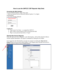


© Copyright 2026