
Survey (pdf 284KB) - Asset Standards Authority
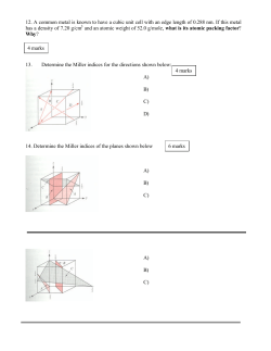
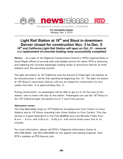
TN 001: 2015 For queries regarding this document [email protected] www.asa.transport.nsw.gov.au Technical Note TN 001: 2015 Issued date Effective date 06 January 2015 06 January 2015 Subject: Project obligations relating to survey assets This technical note is issued by the Asset Standards Authority to clarify the requirements of TMC 212 Survey, version 1.2. 1. Background Track location is defined by the mathematical relationship of different elements of curves and straights that the track traverses. This relationship is known as track alignment, whereby the different elements of straights, curves and transition curves are tied together by coordinated geometry to conform to minimum requirements. Coordinated track alignment is based upon the Rail Survey Control Network, which is underpinned by the NSW State Survey Control Network. This network is represented on the ground within the rail corridor by Rail Survey Control Marks. These marks are fundamental rail assets that have been coordinated in three dimensions, and provide a reference network for track alignment. Track Control Marks (TCM's) provide further densification of survey marks within the corridor. These marks are located at regular intervals on both sides of the corridor, and together with the plaques related to the mark, provide a direct reference for rail maintenance and construction personnel to locate the track in its correct spatial location. The purpose of this technical note is to reinforce the requirement for any project work being undertaken within the corridor to install, preserve, or replace these survey assets. It is mandatory to identify any activities that are likely to affect or disturb the location of existing survey marks, and any activities that result in new infrastructure requiring the installation of new survey marks. These requirements are outlined in the following sections of this technical note. © State of NSW through Transport for NSW Asset Standards Authority Page 1 of 3 TN 001: 2015 2. Planning stage survey requirements During the planning stage and prior to any work taking place, the Principal Surveyor of the relevant Rail Infrastructure Manager (RIM), for example Sydney Trains, shall be consulted regarding survey issues within the proposed 'work-zone'. This consultation shall consider the most appropriate corridor survey control marking strategy and coordinate system to be adopted for the project. Consultation is normally conducted with the project's survey representative, who will have an appreciation of the issues from both perspectives. A project plan shall be jointly developed to identify any likelihood of disturbance. Where it is identified that survey marks will be disturbed or destroyed, a remediation plan shall be agreed to. Action to replace a damaged or disturbed survey mark shall be organised before the damage or disturbance occurs. 3. Completion stage survey requirements At the completion of the project, information detailing the coordination of Rail Survey Control Marks and TCM's shall be provided to the Principal Surveyor, in the form of a report signed by a Registered Surveyor. Information shall include the following: • final 3D coordinates of all survey marks • documentation of adjustments • deliverables as required in SPC 211 Survey and TMC 212 Survey Examples of the types of projects that have the potential to disturb, damage, or destroy rail survey marks include the following: • platforms works – including reconstruction, re-sheeting, replacement • cutting and embankment widening • overhead wiring structure (OHWS) replacement • track reconstruction works • rerailing • excavation and other construction activities within the corridor Any activity or project that requires reinstatement or installation of survey assets including survey plaques shall be undertaken as a cost to the project. In some cases, the use of rail specialist survey personnel may be required to complete the works and reporting requirements to the satisfaction of the Principal Surveyor. All newly-installed marks, or marks requiring re-observation due to disturbance, shall be observed and connected to the existing survey network following the procedures outlined within the standards. Use of prescribed mark types and survey plaques is also a mandatory requirement. This hardware may be sourced in consultation with the Principal Surveyor. © State of NSW through Transport for NSW Asset Standards Authority Page 2 of 3 TN 001: 2015 For any other issues that require clarification or interpretation, the project should contact the Principal Surveyor at the earliest opportunity. Authorisation Technical content prepared by Checked and approved by Interdisciplinary coordination checked by Authorised for release Name David Brown John Paff David Spiteri Graham Bradshaw Position Senior Surveyor Lead Track Engineer Chief Engineer Rail Principal Manager Network Standards & Services Signature © State of NSW through Transport for NSW Asset Standards Authority Page 3 of 3 Engineering Manual Track SURVEY Version 1.2 Issued December 2009 Owner: Chief Engineer Track Approved by: Graeme Gaggin Principal Surveyor Authorised by: Malcolm Kerr Chief Engineer Track Disclaimer This document was prepared for use on the RailCorp Network only. RailCorp makes no warranties, express or implied, that compliance with the contents of this document shall be sufficient to ensure safe systems or work or operation. It is the document user’s sole responsibility to ensure that the copy of the document it is viewing is the current version of the document as in use by RailCorp. RailCorp accepts no liability whatsoever in relation to the use of this document by any party, and RailCorp excludes any liability which arises in any manner by the use of this document. Copyright The information in this document is protected by Copyright and no part of this document may be reproduced, altered, stored or transmitted by any person without the prior consent of RailCorp UNCONTROLLED WHEN PRINTED Control Pages – Page 1 of 2 Engineering Manual TMC 212 RailCorp Engineering Manual — Track Survey TMC 212 Document control Revision Date of Approval Summary of change 1.2 December, 2009 Changes detailed in Chapter Revisions 1.1 December, 2008 Section C2-1 - Change to SMS document reference for testing of survey staves; Section C2-2.1 - Change to installation requirements for marks 1.0 October, 2007 First issue as a RailCorp document. Includes content from TS 2621, C 4610, C 4611, C 4613 Summary of changes from previous version Chapter Current Revision Pages Date of Approval Control Pages 1.2 2 December, 2009 Change of format for front page, change history and table of contents December, 2009 Changes to reflect change in titles Various Summary of change 1 1.1 1 December, 2009 Format change only 2 1.2 4 December, 2009 Format change only 3 1.1 5 December, 2009 Format change only Appendix 1 1.1 1 December, 2009 Format change only Contents Chapter 1 C1-1 C1-2 C1-3 C1-4 Chapter 2 C2-1 C2-2 Chapter 3 C3-1 C3-2 C3-3 Appendix 1 Introduction ............................................................................................................................ 1-1 Purpose .........................................................................................................................................1-1 Context ..........................................................................................................................................1-1 How to read the Manual ................................................................................................................1-1 References ....................................................................................................................................1-1 RailCorp Survey Control Network........................................................................................ 2-1 Instruments and Equipment ..........................................................................................................2-1 Survey Control ..............................................................................................................................2-1 RailCorp Track Control Network .......................................................................................... 3-1 Instruments and Equipment ..........................................................................................................3-1 Track Control.................................................................................................................................3-1 Track Control Mark Plaques..........................................................................................................3-4 Plaque Engraving – Data requirements............................................................................ A1-1 © Rail Corporation Issued December 2009 UNCONTROLLED WHEN PRINTED Control Pages – Page 2 of 2 Version 1.2 RailCorp Engineering Manual — Track Survey TMC 212 Chapter 1 Introduction C1-1 Purpose This manual provides requirements, processes and guidelines to be used when conducting a survey of the RailCorp Survey Control and Track Control Networks. It does not include the use of GPS equipment. C1-2 Context The manual is part of RailCorp's engineering standards and procedures publications. More specifically, it is part of the Civil Engineering suite that comprises standards, installation and maintenance manuals and specifications. Manuals contain requirements, processes and guidelines for the management of track assets and for carrying out examination, construction, installation and maintenance activities. The manual is written for the persons undertaking installation and maintenance activities. C1-3 How to read the Manual The best way to find information in the manual is to look at the Table of Contents starting on page 2. Ask yourself what job you are doing? The Table of Contents is written to reflect work activities. When you read the information, you will not need to refer to RailCorp Engineering standards. Any requirements from standards have been included in the sections of the manual and shown like this: The following requirements are extracted from RailCorp Standard ESC 210 Track Control Marks to define alignment and grade shall be placed as detailed in Table 3. MR Reference is however made to other Manuals. C1-4 References C1-4.1 Australian and International Standards Nil C1-4.2 RailCorp Documents ESC 210 – Track Geometry and Stability SPC 211 – Survey Specification SMS-06-SW-0275 Annual Insulation Resistance Testing of Survey Staves © Rail Corporation Issued December 2009 UNCONTROLLED WHEN PRINTED Chapter 1 – Page 1 of 1 Version 1.2 RailCorp Engineering Manual — Track Survey TMC 212 Chapter 2 RailCorp Survey Control Network This specification outlines the field procedures to be followed when conducting a survey of the RailCorp Survey Control Network. This specification does not include the use of GPS equipment. C2-1 Instruments and Equipment All instruments and equipment used for survey of the RailCorp Survey Control Network shall be in accordance with SPC 211 Survey Specification. Only non-conducting timber or fibreglass survey staves are to be used. All staves must be tested and tagged in accordance with SMS-06-SW-0275 – Survey Staves used around 1500vdc equipment - Annual Testing of Insulation Resistance. Use of metallic staves and Invar staves is not permitted on any RailCorp project. C2-2 Survey Control C2-2.1 Types of Survey Mark The types of marks that may be placed for the purpose of the RailCorp Survey Control Network are as described in Table 1. Type Description Reference Remark Rail Survey Mark (RSM) Long brass pin and triangle. Short Brass pin and triangle Figure 1 Placed in bed rock, concrete, stone or masonry. RSM to be recessed so that the top of the triangle is flush with the surrounding material Rail Survey Mark (RSM) Long brass pin and triangle cast in concrete with cast iron box cover. Figure 2 Placed in stable soil or firm ground. Rail Survey Mark (RSM) Long brass pin and triangle cast in concrete with cast iron box cover. Galvanised iron or aluminium star picket set in concrete below ground level. Figure 3 Placed in locations where additional support is required. This type of mark to be used only if above types are unsuitable. Table 1 – Survey Marks In special circumstances other types of mark may be proposed for approval of the Principal Surveyor or the District Surveyor. Note that before any mark is installed it is recommended that a services search be undertaken. C2-2.2 Placement of Survey Marks Survey Control marks are to be placed at a maximum spacing of 150m. At intervals of approximately 500m the placement of the Rail Survey Control mark is to allow for connection to the Lands Department Control marks outside of the RailCorp corridor. This connection is to be by line of sight techniques with a minimum distance of 200m. © Rail Corporation Issued December 2009 UNCONTROLLED WHEN PRINTED Chapter 2 – Page 1 of 4 Version 1.2 RailCorp Engineering Manual — Track Survey TMC 212 Rail Survey Control Marks must be placed in stable structures clear of running lines and as far as is practical clear of access roads and other areas that may pose a risk to survey staff when occupying the mark. Where the above criteria cannot be met, approval to vary the criteria must be sought from the Principal Surveyor or the District Surveyor. Top of triangle flush with surrounding material 3mm 40mm Epoxy resin Set in epoxy resin in concrete or masonry 13mm dia 10mm 70mm Figure 1 – Rail survey Mark – Triangle type Hinged Cast Iron Box 100mm Ground Surface 450mm 100mm Brass Triangle Long pin In situ mass concrete In situ mass concrete Figure 2 – Survey mark with Triangle C2-2.3 Figure 3 – Survey mark with Star picket Documentation Each Rail Survey Mark (RSM) must be documented with a Rail Survey Mark Sketch Plan. See Figure 4. The Rail Survey Mark Sketch Plan must contain: − Kilometrage of the mark. − Distance to adjacent Rail Survey Control Marks. − Offset of the mark from the running face of the nearest rail. © Rail Corporation Issued December 2009 UNCONTROLLED WHEN PRINTED Chapter 2 – Page 2 of 4 Version 1.2 RailCorp Engineering Manual — Track Survey TMC 212 − A minimum of three connections with bearing and/or distances to nearby identifiable features. − Features such as tracks, fences, poles, etc should be shown with measurements of appropriate accuracy. Each sketch should be oriented to the north with either grid or magnetic bearings shown. Rail Survey Mark Sketch Plans are to be provided in both hard copy and electronic TIFF formats. © Rail Corporation Issued December 2009 UNCONTROLLED WHEN PRINTED Chapter 2 – Page 3 of 4 Version 1.2 RailCorp Engineering Manual — Track Survey TMC 212 RAIL SURVEY MARK SKETCH PLAN Line: Locality: Km: Location: Up Side Down Side O/S to NR: N CO-ORDINATES E: SOURCE PLACED BY: N: DATE: RL: SYSTEM ZONE DATUM: ISG: MGA: OTHER: DATE OF SURVEY: Figure 4 - Rail Survey Mark Sketch Plan © Rail Corporation Issued December 2009 UNCONTROLLED WHEN PRINTED Chapter 2 – Page 4 of 4 Version 1.2 RailCorp Engineering Manual — Track Survey TMC 212 Chapter 3 RailCorp Track Control Network This specification outlines the field procedures to be followed when conducting a survey of the RailCorp Track Control Network. C3-1 Instruments and Equipment All instruments and equipment used for survey of the RailCorp Survey Control Network shall be in accordance with SPC 211 Survey Specification. Only non-conducting timber or fibreglass survey staves are to be used. All staves must be tested and tagged in accordance with SMS-06-SW-0275 - Annual Insulation Resistance Testing of Survey Staves. Use of metallic staves and Invar staves is not permitted on any RailCorp project. C3-2 Track Control C3-2.1 Types of Track Control Mark The types of marks that may be placed for the purpose of the RailCorp Track Control Network are as described in Table 2. Type Track Control Mark (TCM) Description Stainless Steel Pin Reference Figure 5 Remark Placed in OHWS or other metallic structure. See Figure 7. Pin requires No. 20 drill for installation. The internal surface of the drill hole shall be coated with a paint product such as Galmet prior to the placement of the TCM. Track Control Mark (TCM) Brass pin (type 3). Figure 6 Placed in stable rock, concrete or masonry. See Figure 7. Pin requires 12mm drill for softer material such as brick or 13mm drill for hard materials such as concrete. When using 13mm drill adhesive such as Araldite must be used during installation. Track Control Mark (TCM) Punch Mark in galvanised iron or aluminium star picket set in concrete at ground level. Figure 3 Placed in stable soil or firm ground. This type of mark to be used only if above types are unsuitable. A metal tag must be attached to the picket with stainless steel tie wire or set in the concrete adjacent to the picket to provide a unique identifier. Table 2 – Track Control Marks In special circumstances other types of mark may be proposed for approval of the Principal Surveyor or the District Surveyor. © Rail Corporation Issued December 2009 UNCONTROLLED WHEN PRINTED Chapter 3 – Page 1 of 5 Version 1.2 RailCorp Engineering Manual — Track Survey 7 11 4.2±0.1 6 3.7±0.1 TMC 212 2 20 2 X 1mm chamfer 12 – 12.7 Figure 5 – Stainless Steel Pin 90 - 100 2 Figure 6 – Brass Pin Type 3 (Brass Rod) C3-2.2 Placement of Track Control Marks The following requirements are extracted from RailCorp Standard ESC 210 Track Control Marks to define alignment and grade shall be placed as detailed in Table 3. Location MR Spacing Straights Every 20m Circular curves and transition curves Every 10m Platforms Either end (100mm in) and every 10m Overbridge Abutments and tunnels Either end (100mm in) and every 10m Table 3 –- Placement of Survey Control Marks Track control marks are as far as is practical placed on stable permanent structures adjacent to the tracks. (Overhead Wiring structures and other similar structures) Track control marks are as far as is practical placed in stable permanent structure adjacent to the tracks. They are to be placed at a nominal 20m interval generally and at a nominal 10m interval in platforms, tunnels, bridges and other locations with restricted clearances. A mark is to be placed at the entrance and exit of these structures as indicated in Figure 7. All Track Control marks are to be assigned a unique identifier. © Rail Corporation Issued December 2009 UNCONTROLLED WHEN PRINTED Chapter 3 – Page 2 of 5 Version 1.2 RailCorp Engineering Manual — Track Survey TMC 212 Sydney Country TCM TCM TCM H - Frame A - Frame PP Mast Sketch A – OHW structures 100mm 100mm 100mm 100mm 100mm 100mm TCMs shown as O Required track location shown as Sketch B - Overbridges Abutments & piers Ballast wall Sketch C - Transom Top Underbridges Sketch D - Ballast Top Underbridges TCMs and Track location at 20m intervals on long underbridges On short Ballast Top underbridges, Track location at underbridge is sufficient Figure 7 – Location of Track Control Marks (TCM) © Rail Corporation Issued December 2009 UNCONTROLLED WHEN PRINTED Chapter 3 – Page 3 of 5 Version 1.2 RailCorp Engineering Manual — Track Survey C3-2.3 TMC 212 Standards of accuracy The following requirements are extracted from RailCorp Standard ESC 210 Where standards of accuracy are not nominated in the design, all marks shall be placed to an accuracy, relative to adjacent marks, of at least twice the accuracy standards defined in Section 11.1.2 for track construction standards. C3-2.4 MR Documentation The Track Control Mark (TCM) must be documented by recording the following information into a spreadsheet: − Track Referenced (maximum of 10 characters) − Location of TCM with respect to track referenced (up or down side) − OHWS Identification (if applicable) (maximum of 10 characters) − Kilometrage of the TCM (truncated to whole Km only) − Approximate metrage of TCM on referenced track (m) − Identifier i.e. TCM point number (maximum 5 characters) The Track Control Mark spreadsheet is to be provided in both hard copy and electronic (.xls) formats. C3-3 Track Control Mark Plaques The following requirements are extracted from RailCorp Standard ESC 210 Each Track Control Mark shall be referenced by a Survey Plaque containing, at least, the following information: - Track referenced - OHWS Identification (if applicable) - Kilometrage of TCM to 1mm (eg 49km 357.345m) - Design Track Centres from referenced track to adjacent track (if applicable) - Design superelevation of referenced track (mm) - Horizontal offset from TCM to Design running face of nearest rail of referenced track (mm) - Vertical offset from TCM to Design Low (datum) Rail of referenced track (mm) MR A standard aluminium plaque shall be attached to any structure in which a Track Control mark is installed. The plaque must be placed adjacent to the Track Control Mark. If a Track Control Mark references more than one track then an additional plaque is required for each track referenced. The format of the plaques is as is shown in Figure 8 The information to be shown on the plaque is as described in Appendix 1. C3-3.1 Installation of Plaques Plaques shall be fixed to metal structures by use of 4mm diameter Aluminium pop rivets (3.2mm to 4.8mm material thickness). Two rivets only required placed in the centre holes at the top and bottom of the plaque. Drill size No.20 as used for the stainless steel TCM is suitable for this purpose. The internal surface of drill holes shall be coated with a paint product such as Galmet prior to the placement of the rivet. © Rail Corporation Issued December 2009 UNCONTROLLED WHEN PRINTED Chapter 3 – Page 4 of 5 Version 1.2 RailCorp Engineering Manual — Track Survey TMC 212 Plaques shall be fixed to non-metallic structure using 4 (one in each corner) 5mm diameter, 25mm depth nylon anchors. These anchors require the use of a 5mm masonry drill for installation. 75 37.5 3 3 SURVEY Track Control Mark 4 2 4 km 3 3 SUPER mm 5 3 2 OFFSET TO NEAR RAIL mm 3 HEIGHT TO NEAR RAIL mm 3 DO NOT DEFACE 5 dia 150 CENTRES mm Equal Spacing 10 1.5 4 11.5 6 All dimensions are in mm 6 Figure 8 – Specification for Track Control Marks (TCM) Lettering Height Top and Bottom Headings 4mm Elsewhere 3mm Depth 0.4mm Lowercase = 75% of uppercase Height : Thickness 5:! Style Gothic Lines Thickness 0.6mm Material Type Marine Grade Aluminium 5251 W34 Anodised 20 micron Thickness 1.5mm © Rail Corporation Issued December 2009 UNCONTROLLED WHEN PRINTED Chapter 3 – Page 5 of 5 Version 1.2 RailCorp Engineering Manual — Track Survey TMC 212 Appendix 1 - Plaque Engraving – Data requirements To enable efficient plaque production, all plaquing data is to be supplied in the following format. Data is to be supplied electronically (i.e. on disk or via email). Data is to be supplied in a spreadsheet format, MS Excel is preferred, MS Works or Lotus 123 is acceptable. The spreadsheet columns are to be as shown: Column 1: Track Referenced (max. 10 characters) Column 2: OHWS Identification (if applicable) (max. 10 characters) Column 3: Kilometrage of TCM (Truncated to whole Km only) Column 4: Metrage of TCM on Referenced Track (do not show Km) (metres) Column 5: Design Track Centres of Referenced Track to Adjacent Track (if applicable) (mm) Column 6: Design Superelevation of Referenced Track (mm) Column 7: Horizontal Offset from TCM to Design Running Face of Near Rail of Referenced Track (mm) Column 8: Vertical Offset from TCM to Design Low (Datum) Rail of Referenced Track (mm) Column 9: Identifier i.e. TCM Point No., etc (max. 5 characters) Notes: Column 7: Horizontal offset is in millimetres and is positive only. Column 8: A negative vertical offset indicates that the low rail is below the TCM Column 9: The Identifier is included to enable the plaque to be fixed to the correct structure, i.e. this information ties the plaque /plaques to a particular TCM. Example spreadsheet DOWN MAIN 31+855 31 852.461 3810 110 2422 -792 1947 DOWN MAIN 31+896 31 892.723 3810 110 2392 -354 1951 DOWN MAIN 31+940 31 937.808 3810 110 2424 -558 1954 DOWN MAIN 32+436 32 430.548 3810 110 2601 -767 2503 DOWN MAIN 32+616 32 604.914 3810 92 2388 -408 2516 © Rail Corporation Issued December 2009 UNCONTROLLED WHEN PRINTED Appendix 1 – Page 1 of 1 Version 1.2


© Copyright 2026