
Drive Technology
762
Drive Technology
Drive Technology
Drive Technology
The drive system for highly dynamic positioning tasks
763
Drive Technology
820
770
Digital Compact Servo Drives
790
Synchronous Servomotors
Linear Servomotors
830
Compact Drive Technology
842
XTS (eXtended Transport System)
764
Drive Technology
Servo Drives, Servo and Linear Motors,
Compact Drive Technology and XTS
766
768
770
System overview
Servo Drives
788
Servo and Linear Motors
830
Compact Drive Technology
790
Synchronous Servomotors
832
Product overview
792
One Cable Technology (OCT)
793
Motor series AM8000
834
Motor series AM8100
801
Motor series with higher moment
834
Motor series AM3100
of inertia AM8500
836
Connection cables
Stainless steel motor series
837
Planetary gear units AG2250
Digital Compact Servo Drives
AX5000
810
771
Highlights
772
System description
814
Motor series AM3000
838
Stepper Motors AS1000
776
1-channel up to 28 kW AX51xx
818
Motor series with higher moment
840
Connection cables
778
2-channel up to 8.3 kW AX52xx
of inertia AM3500
841
Planetary gear units AG1000
780
1-channel up to 118 kW AX51xx
820
Linear Servomotors
782
Options
823
Linear Servomotors AL2000
782
Encoder option cards AX57xx
824
Linear Servomotors AL2400
842
XTS
782
TwinSAFE drive option cards
825
Linear Servomotors AL2800
AX58xx
826
Accessories
854
Motor modules AT200x
807
Planetary gear units
855
Movers AT9011
807
Planetary gear units AG2210
856
Software TF5850
813
Stainless steel planetary gear
858
Guide rails AT9xxx
783
AX-Bridge quick connection
system AX59xx
784
AM8800
Connection cables
(eXtended Transport System)
786
Accessories
837
Planetary gear units AG2250
784
Accessories
784
Motor cables
785
Resolver cables
829
Connectors
www.beckhoff.com/DriveTechnology
Drive Technology
units AG2800
765
Drive Technology
Beckhoff Drive Technology
766
Servo Drives
Servomotors
The Servo Drives of the AX5000 series impress with their versatile
functionality and high efficiency. The integrated, fast control technology with a current control cycle of up to 62.5 µs supports fast and
highly dynamic positioning tasks. EtherCAT as high-performance system communication enables ideal interfacing with PC-based control
technology and supports coupling with other communication systems.
The Servomotors are characterised by high dynamics as well as
energy and cost efficiency. They are available with stainless steel
housings (AM8800), certified according to EHEDG is this execution
particularly suitable for applications in the food and beverage industries. The AM8500 series is specially designed for applications with
high load moments of inertia or high synchronism demands. To further
enhance their performance the AM8000 and AM8500 series can be
equipped with an external fan. The AL2000 iron-core linear motors
offer high continuous forces.
See page
Accessories see page
770
782
Synchronous Servomotors see page
Linear Servomotors see page
Accessories see page
www.beckhoff.com/Servo-Drives
790
820
784
www.beckhoff.com/Servomotors
We reserve the right to make technical changes.
eXtended Transport System
In the low-voltage range up to 50 V, Beckhoff offers a wide range of
components for compact drive solutions, particularly for stepper and
servomotors. In conjunction with IP 20 stepper motor terminals or IP 67
EtherCAT Box modules, the AS1000 stepper series can be operated as
an adjustable axis, either with or without feedback. The AM8100 and
AM3100 servomotor series can be used in conjunction with the EL72xx
servo terminal to configure a very compact drive axis. A consistently costoptimised feedback system resolver is available for both motor series.
The AM8100 series supports One Cable Technology (OCT) and therefore
offers the benefits of an electronic name plate and multi-turn absolute
encoder function. Pre-assembled cables and specially adapted planetary
gear units round off the product range of Compact Drive Technology.
The XTS linear transport system (eXtended Transport System)
from Beckhoff combines all drive technology functions in a single
mechatronic system: motor movement, power electronics and displacement measurement form a technical unit which can be used
to implement a wide range of complex movements. A user-friendly
programming interface enables different movements to be realised
simultaneously directly from TwinCAT with little effort. The modular
XTS system enables fast adaptation of a transport concept to different
geometries and applications.
See page
System description see page
Mechanical components see page
Accessories see page
842
854
856
830
www.beckhoff.com/compact-drive-technology
We reserve the right to make technical changes.
www.beckhoff.com/XTS
Drive Technology
Compact Drive Technology
767
Drive Technology
Servo Drives
768
AX5101–AX5112, AX52xx | Digital Compact
Servo Drives: 1-/2-channel up to 8.3 kW
– 1- or 2-channel Servo Drives
– high-speed EtherCAT communication
– rated current up to 12 A or 2 x 6 A
– optimised for multi-axis applications
– variable motor output current for
2-channel Servo Drives
See page
776
We reserve the right to make technical changes.
EL7201 | Ultra-compact servo terminal
in 12 mm I/O housing up to 170 W
– complete servo drive on 12 mm
– seamless integration into EtherCAT I/O
system
– US 8…50 V DC, IMAX 2.8 ARMS
– field-oriented control for highly dynamic
positioning tasks
– tailored to AM8100
EL7211 | Compact servo terminal
in 24 mm I/O housing up to 245 W
– complete servo drive on 24 mm
– seamless integration into EtherCAT I/O
system
– US 8…50 V DC, IMAX 4.5 ARMS
– field-oriented control for highly dynamic
positioning tasks
– tailored to AM8100
See page
See page
431
Drive Technology
431
769
AX5118–AX5140 | Digital Compact
Servo Drives: 1-channel up to 28 kW
– high-speed EtherCAT communication
– rated current: 18/25/40 A
– flexible motor type selection
AX5160–AX5193 | Digital Compact
Servo Drives: 1-channel up to 118 kW
– high-speed EtherCAT communication
– rated current: 60/72/90/110/143/170 A
– high performance with small dimensions
– flexible motor type selection
See page
See page
776
www.beckhoff.com/Servo-Drives
We reserve the right to make technical changes.
780
AX5000 | Digital Compact
Servo Drives
Optional slot for interface
boards, e.g. additional feedback
Optional slot for
TwinSAFE safety cards
Motor feedback:
Sin/Cos 1 Vpp, EnDat,
Hiperface, BiSS
Motor feedback (only for
AX52xx 2-axis module): Sin/Cos
1 VPP, EnDat, Hiperface, BiSS
Motor feedback:
resolver
Motor feedback (only for
AX52xx 2-axis module): resolver
8 digital I/Os,
e.g. enable, limit switch,
capture input,
error message
Status display,
e.g. axis identifier
or a diagnostic message
Navigation buttons
EtherCAT system bus
Operating material identification
Drive Technology
24 V DC control
and braking voltage
770
DC-Link system
or external
braking resistor
Power supply
100 V AC -10 % …
480 V AC +10 %
Motor outputs
Brake control,
motor temperature
monitoring, OCT
We reserve the right to make technical changes.
AX5101–AX5112 |
AX52xx | 2-channel,
AX5118–AX5140 |
AX5160, AX5172 |
AX5190, AX5191 |
AX5192, AX5193 |
1-channel, up to 12 A
up to 2 x 6 A
1-channel, 18/25/40 A
1-channel, 60/72 A
1-channel, 90/110 A
1-channel, 143/170 A
The EtherCAT drives
The AX5000 Servo Drive product line from
Beckhoff sets new standards in drive performance. The AX5000 series is available
in single- or multi-channel form and is
optimised for exceptional functionality and
cost-effectiveness. Featuring integrated,
high-speed control technology with a current
control cycle of down to 62.5 µs, the AX5000
drives support fast and highly dynamic positioning tasks. The drives utilise EtherCAT as
a high-performance communication system,
providing an ideal interface with PC-based
control technology while supporting coupling
with other fieldbus systems. The 2-channel
Servo Drives with variable motor output cur-
rent optimise the packaging density and the
cost per drive channel. The compact design
and simple and safe installation through the
“AX-Bridge” quick connection system significantly simplify control cabinet assembly.
–
fast control technology
– current control: min. 62.5 µs
– speed control: min. 125 µs
– position control: min. 250 µs
–
variably adjustable current and speed filters
–
high-speed EtherCAT system communication
–
1- or 2-channel Servo Drive
– optimised for multi-axis applications
– variable motor output current in 2-channel drives
–
active DC-Link and brake energy management
–
variable motor interface with
– multi-feedback interface
– flexible motor type selection
– scalable, wide range motor current measurement
– OCT (One Cable Technology)
www.beckhoff.com/AX5000
We reserve the right to make technical changes.
–
high-speed capture inputs
–
wide voltage range 100…480 V AC
–
integrated mains filter
–
integration of safety functions (optional)
– restart lock
– TwinSAFE: intelligent safety functions
for Motion Control
–
compact design for simple control cabinet
installation (300 mm depth)
Drive Technology
Technical highlights
771
–
AX-Bridge – the quick connection system for
power supply, DC-Link and control voltage
–
variable cooling concept
(fanless, forced cooling)
1-axis AX51xx Servo Drive for a single motor
2-axis AX52xx Servo Drive for two motors
up to 170 A rated current
with a total current up to 12 A
AX5000 | System overview
The AX5000 Servo Drive series enhances the Beckhoff drive range
with a generation of drives for fast and highly dynamic positioning
tasks. The universal drive concept is suitable for almost any application
and system requirement.
AX51xx | 1-channel Servo Drive
– Servo Drive for one drive axis
– rated current: 1.5 A, 3 A, 6 A, 12 A, 18 A, 25 A, 40 A, 60 A, 72 A,
90 A, 110 A, 143 A, 170 A
– wide voltage range: 100 V AC -10 %…480 V AC +10 %
– AX5160…AX5193: 3 x 400 V AC -10 %…3 x 480 V AC +10 %
AX5021 | Brake module
The brake module consists of an internal braking resistor with a
continuous power of 250 W, forced cooling and a brake chopper.
An external braking resistor with a continuous power of up to 6 kW
can be connected to the brake chopper. The module has a 705 µF
auxiliary capacitance for storing braking energy that can be released
again for subsequent acceleration. The application of the brake module increases the efficiency of the whole drive system. Connection
of the brake module with the multi-axis system is straightforward
via the AX-Bridge module. The integrated EtherCAT interface enables
parameterisation and diagnosis via the System Manager.
Drive Technology
AX52xx | 2-channel Servo Drive
– Servo Drive for two drive axes
– rated current: 2 x 1.5 A, 2 x 3 A, 2 x 6 A
– flexible allocation of the total device current to both axes
– wide voltage range: 100 V AC -10 %…480 V AC +10 %
772
The double width of the AX5118 up to the AX5140
(rated current 18/25/40 A) compared to AX5x01–AX5112
supports modular control cabinet installation.
We reserve the right to make technical changes.
Multi-feedback interface for all common
Ultra high-speed communication via
Connection module with power rail system for
feedback systems and connection option
EtherCAT enables update times of 100 µs
multi-axis systems, current carrying capacity
for an additional encoder
for 100 axes.
up to 85 A.
AX5000 | High-speed Servo Drives
High-speed EtherCAT system communication
The AX5000 was developed specifically for use with EtherCAT,
the real-time Ethernet system. The outstanding features of EtherCAT
are particularly beneficial for Drive Technology:
– Ethernet right down to the I/O terminal and drives
– high-precision system synchronisation through
distributed clocks
– high-speed capture with time stamp, e.g. for print mark control
– ultra high-speed communication with update times of:
– 100 axes in 100 µs
– 1,000 distributed I/Os in 30 µs
– transparent line topology with flexible branches
– simple system wiring using Industrial Ethernet patch cables
2-channel Servo Drive with variable motor output current
One highlight of the AX5000 series is the dual power section that
enables operation of two motors with the same or different current
within a single Servo Drive. An asynchronous motor with a rated
current of 3 A and a linear motor with a rated current of 9 A can be
operated with a 2 x 6 A Servo Drive, for example. The total current is
relevant for the device utilisation.
– For two-channel devices (AX5206) the channel current is
adjustable between 1…9 A.
– “Active current sensing” automatically and optimally adapts
the current resolution to the connected current.
We reserve the right to make technical changes.
Optimised for multi-axis applications
The AX5000-Bridge system enables simple and fast connection to
several AX5000 devices with a multi-axis system through pluggable
feed and connection modules:
– integration of power supply, DC-Link, 24 V DC control and
braking voltage
– connection module with power rail system, current carrying
capacity up to 85 A
– straightforward installation and disassembly without additional
wiring effort
– visible and safe contacting
Active DC-Link and brake energy management
With the AX-Bridge, the DC-Links are automatically connected
through: This ensures economic energy balancing between axes.
– short-circuit-proof
– intelligent utilisation of all available system ballast resistors
– avoiding power loss
Braking resistor
The integrated braking resistor is sufficient for most applications.
In multi-axis systems the overall braking capacity of all braking
resistors is available. The brake module enables external ballast resistors with a continuous output up to 6 kW to be connected, making
extreme applications possible.
Further components for regenerative braking management
see page 786
Drive Technology
High-speed control algorithms
The AX5000 Servo Drives are designed for fast and highly
dynamic positioning tasks:
– current controller with cycle times down to 62.5 µs
for highly dynamic regulation of ironless linear motors
or low-induction motors
– speed controller 125 µs
– position controller 250 µs
773
Connection module with
power rail system for multiaxis systems, current carrying
capacity up to 85 A
Power supply module
Power distribution module
AX5901 with snap-on connec-
AX5911 with snap-on connection
tion for the Servo Drive
for power supply, DC-Link and
control voltage
AX5000 | One for all
Drive Technology
Variable motor interface
The AX5000 offers flexible and universal connection options.
Almost all feedback systems and motor types are supported.
The AX5000 supports the feature “electronic name plate”, which
simplifies commissioning and operation. The AX5000 is very flexible
with regard to supported motor types; different motor sizes and
types can be connected without additional measures, e.g.:
– synchronous motors
– linear motors
– torque motors
– asynchronous motors
Multi-feedback interface
AX5000 supports the right feedback system for any application:
– resolver
– One Cable Technology (OCT), single- and multi-turn
– SinCos encoder 1 VPP
– single- or multi-turn encoder with Hiperface,
EnDat or bidirectional sensor interface (BiSS)
– connection option for further feedback with option card AX57xx
– HTL
– EnDat 2.2
– BiSS C
774
Flexible motor current measurement
The AX5000 enables a scalable, wide range motor current measurement with high-resolution measuring range specification.
A 6 A amplifier can control a 1 A motor without loss of measuring
resolution. For 2-channel devices the total device current is significant: 12 A = 2 x 6 A or 1 x 3 A + 1 x 9 A.
High-speed capture inputs
Each AX5000 Servo Drive features eight additional on-board,
programmable digital I/Os:
– choice of standard functions such as enable, output stage lock
or axis-limit switches
– Due to the short response time of 11 µs, two of these inputs
can also be used as capture inputs with time stamp.
– Possible applications include precise referencing and measurement processes or print mark control.
– Three digital outputs for controlling the motor brake or fault
reporting are also integrated.
– Additional integrated functions include smooth start-up,
overvoltage detection, short circuit protection and phase failure
monitoring.
Diagnostic and parameter display
The AX5000 features a backlit, two-line plain text display. This display
enables fast device diagnosis and maintenance on site. In two-channel
devices the axis identifier is also displayed. Navigation buttons enable
simple and convenient operation of the diagnostic display.
Wide voltage range
The AX5000 can be connected to a wide range of voltage systems
worldwide without additional components, including 1 x 100 V AC,
for the Japanese market or 3 x 480 V AC for North America, for example. This significantly reduces the inventory management effort for
the machine manufacturer and minimises the risk of damage through
incorrect mains connection.
– can be used in all supply networks worldwide
– No additional transformers or mains chokes are required.
We reserve the right to make technical changes.
Integration of safety functions
Variables Motorinterface
Variable motor interface
Compact design for simple control cabinet installation
The AX5000 Servo Drive series (up to 40 A) enables simple and fast
connection of several drives to form a multi-axis system via AX-Bridge
modules. The pluggable supply and connection module combines supply voltage, DC-Link, 24 V DC control and braking voltage. It enables
fast installation and commissioning. The system consists of:
– AX5901/AX5902 power supply module with snap-on
connection on the Servo Drive
– AX5911/AX5912 power distribution module for multi-axis
systems with integrated power rails
Optimum cooling concept
The specially developed heat sink enables fanless operation of the
AX5000 through natural convection of up to 2 x 3 A rated current.
Devices with higher output feature integrated, temperature-controlled
ventilation.
Controlled system stop in the event of power failure
A power failure can lead to uncontrolled run-out of drive axes,
which means that linear axes or lifting axes would hit the limit stop
unbraked. The 24 V DC supply of the AX5000 has two channels so that
separate power supplies can be used for control electronics and brake
control. It enables the supply voltage for the control electronics to
be buffered via the UPS of the Industrial PC until all axes have been
stopped safely.
We reserve the right to make technical changes.
Integration of safety functions
Optional cards are available for different safety categories:
The AX5801 option card offers personal protection against
inadvertent restart of the drive axis (STO/SS1):
– certified according to DIN EN ISO 13849-1:2006 (Cat 4, PL e)
– Safe Torque Off (STO) according to IEC 61800-5-2
– control through safe 24 V DC outputs
– mains voltage and motor line remain connected
The AX5805, AX5806 option cards provide further drive-integrated
safety functions according to IEC 61800-5-2. Control is performed via
EtherCAT/Safety over EtherCAT; no further wiring is required.
– certified according to DIN EN ISO 13849-1:2008 (Cat 4, PL e)
– supported safety functions:
– stop functions (STO, SOS, SS1, SS2)
– speed functions (SLS, SSM, SSR, SMS) with up to 8 speeds
– position function (SLP, SCA, SLI) with reference cams
– acceleration functions (SAR, SMA)
– rotating direction functions (SDIp, SDIn)
For further information on TwinSAFE and the TwinSAFE products
see page 934
Drive Technology
Integrated mains filter
The device features integrated filters for power supply and 24 V DC
auxiliary supply for operation directly from the mains. No additional
shielding is required for the mains cable.
775
AX51xx
AX5101, AX5103, AX5106, AX5112
AX5118, AX5125, AX5140
AX51xx | Digital Compact Servo Drives (1-channel)
Drive Technology
Performance class up to 28 kW
776
The AX5000 Servo Drive series
is available in single- or multichannel form and is optimised
in terms of function and costeffectiveness. Integrated control
technology supports fast and
highly dynamic positioning tasks.
EtherCAT as a high-performance
communication system enables
ideal interfacing with PC-based
control technology.
The AX51xx 1-channel Servo
Drives are designed for rated
currents up to 40 A.
The AX5000 system enables
simple and fast connection of
several AX5000 devices to form
a multi-axis system through
the AX-Bridge quick connection
system. The pluggable supply
and connection module combines power supply, DC-Link
and 24 V DC control and
braking voltage.
A wide range of motor
types can be connected to the
AX5000. Motors of different
size and type can be connected
without additional measures.
Examples include synchronous,
linear, torque and asynchronous
motors. The multi-feedback
interface supports all common
standards.
The AX5000 was developed
specifically for use with EtherCAT.
The outstanding features of
EtherCAT are particularly beneficial for Drive Technology. They
include short cycle time, synchronicity and simultaneity. EtherCAT
enables very short cycle times,
even in networks containing a
large number of devices.
Features
– high-speed EtherCAT
system communication
– rated current: 1.5 A, 3 A,
6 A, 12 A, 18 A, 25 A, 40 A
– wide voltage range:
1 x 100…240 V AC ±10 %
and 3 x 100…480 V AC
±10 %
– active DC-Link and brake
energy management
– multi-feedback interface
– flexible motor type
selection
– scalable, wide range motor
current measurement
– high-speed capture inputs
– diagnostic and
parameter display
– integrated mains filter
Cat. C3, according to
EN 61800-3
–
–
–
–
optional safety functions:
restart lock, intelligent
TwinSAFE safety functions
compact design for simple
control cabinet installation
AX-Bridge – the quick connection system for power
supply, DC-Link and control
voltage
optimised cooling concept
Servo Drives with rated
output currents > 40 A
see page 780
We reserve the right to make technical changes.
AX51xx
Technical data
AX5101
AX5103
AX5106
AX5112
AX5118
AX5125
AX5140
Rated output current at 50 °C
1 x 1.5 A
1x3A
1 x 4.5 A
–
–
–
–
1 x 1.5 A
1x3A
1x6A
1 x 12 A
1 x 18 A
1 x 25 A
1 x 40 A
0.35 A
1A
1A
6A
12 A
12 A
18 A
(1-phase connection)
Rated output current at 50 °C
(3-phase connection)
Minimum rated motor current
at full current resolution
Rated supply voltage
3 x 100…480 V AC ±10 %
3 x 100…480 V AC ±10 %
1 x 100…240 V AC ±10 %
DC-Link voltage
max. 890 V DC
Peak output current (1)
4.5 A
7.5 A
13 A
26 A
36 A
50 A
80 A
120 V (1-/3-phase connection)
0.3 kVA
0.6 kVA
1.2 kVA
2.5 kVA
3.4 kVA
4.8 kVA
8.3 kVA
230 V (1-/3-phase connection)
0.6 kVA
1.2 kVA
2.4 kVA
4.8 kVA
7.2 kVA
10.0 kVA
16.0 kVA
400 V (only 3-phase connection)
1.0 kVA
2.1 kVA
4.2 kVA
8.3 kVA
12.5 kVA
17.3 kVA
28.0 kVA
480 V (only 3-phase connection)
1.2 kVA
2.5 kVA
5.0 kVA
10.0 kVA
15.0 kVA
20.8 kVA
33.0 kVA
Continuous braking power (2)
50 W
50 W
150 W
90 W
200 W
200 W
200 W
Max. braking power (2)
14 kW
14 kW
14 kW
14 kW
27 kW
27 kW
27 kW
Power loss (3)
35 W
50 W
85 W
160 W
255 W
340 W
550 W
System bus
EtherCAT
Weight
4.0 kg
4.0 kg
5.0 kg
5.0 kg
11.0 kg
11.0 kg
14.0 kg
Further information
www.beckhoff.com/AX51xx
Rated apparent power
for S1 operation (selection)
RMS for max. 7 seconds, (2) internal brake resistor, (3) S1 operation, incl. power supply, without brake chopper
Dimensions
AX5101
AX5103
AX5106
AX5112
AX5118
AX5125
AX5140
Height without connectors
274 mm
274 mm
274 mm
274 mm
274 mm
274 mm
274 mm
Width
92 mm
92 mm
92 mm
92 mm
185 mm
185 mm
185 mm
Depth without connectors
232 mm
232 mm
232 mm
232 mm
232 mm
232 mm
232 mm
Ordering information
AX51xx-0000-0200
AX5101-0000-0200
Digital Compact Servo Drive, 1-axis module, 100…480 V AC, rated output current 1.5 A, EtherCAT interface, OCT
AX5103-0000-0200
Digital Compact Servo Drive, 1-axis module, 100…480 V AC, rated output current 3 A, EtherCAT interface, OCT
AX5106-0000-0200
Digital Compact Servo Drive, 1-axis module, 100…480 V AC, rated output current 6 A, EtherCAT interface, OCT
AX5112-0000-0200
Digital Compact Servo Drive, 1-axis module, 100…480 V AC, rated output current 12 A, EtherCAT interface, OCT
AX5118-0000-0200
Digital Compact Servo Drive, 1-axis module, 100…480 V AC, rated output current 18 A, EtherCAT interface, OCT
AX5125-0000-0200
Digital Compact Servo Drive, 1-axis module, 100…480 V AC, rated output current 25 A, EtherCAT interface, OCT
AX5140-0000-0200
Digital Compact Servo Drive, 1-axis module, 100…480 V AC, rated output current 40 A, EtherCAT interface, OCT
777
Compatible with AX5021, AX57xx, AX5801-0200 and AX5805
Options, pre-assembled cables and accessories see page
We reserve the right to make technical changes.
Drive Technology
(1)
782
AX52xx
AX5201, AX5203, AX5206
AX52xx | Digital Compact Servo Drives (2-channel)
Drive Technology
Performance class up to 8.3 kW
778
The AX5000 Servo Drive series
is available in single- or multichannel form and is optimised
in terms of function and costeffectiveness. Integrated control
technology supports fast and
highly dynamic positioning tasks.
EtherCAT as a high-performance
communication system enables
ideal interfacing with PC-based
control technology.
The AX52xx 2-channel
Servo Drive enables operation
of two motors with identical or
even with different power, up to
a total current of 12 A. The multiaxis drives with variable motor
output allocation offer optimised
packaging density and costs per
drive channel.
The AX5000 system enables
simple and fast connection of
several AX5000 devices to form
a multi-axis system through
the AX-Bridge quick connection
system. The pluggable supply
and connection module combines power supply, DC-Link
and 24 V DC control and braking
voltage.
A wide range of motor
types can be connected to the
AX5000. Motors of different
size and type can be connected
without additional measures.
Examples include synchronous,
linear, torque and asynchronous
motors. The multi-feedback
interface supports all common
standards.
The AX5000 was developed
specifically for use with EtherCAT.
The outstanding features of
EtherCAT are particularly beneficial for Drive Technology. They
include short cycle time, synchronicity and simultaneity. EtherCAT
enables very short cycle times,
even in networks containing a
large number of devices.
Features
– high-speed EtherCAT
system communication
– rated current: 2 x 1.5 A,
2 x 3 A, 2 x 6 A
– wide voltage range:
1 x 100…240 V AC ±10 %
and 3 x 100…480 V AC
±10 %
– active DC-Link and brake
energy management
– multi-feedback interface
– flexible motor type
selection
– scalable, wide range motor
current measurement
– high-speed capture inputs
– diagnostic and parameter
display
– integrated mains filter
Cat. C3, according to
EN 61800-3
– optional safety functions:
restart lock, intelligent
TwinSAFE safety functions
–
–
–
compact design for simple
control cabinet installation
AX-Bridge – the quick connection system for power
supply, DC-Link and control
voltage
optimised cooling concept
We reserve the right to make technical changes.
AX52xx
Technical data
AX5201
AX5203
AX5206
Rated output current at 50 °C
2 x 1.5 A
2x3A
2 x 6 A (*)
Minimum rated channel current
0.35 A
1A
1A
3A
4.5 A
9A
3A
6A
9A
at full current resolution
Max. rated channel current
at full current resolution
(1-phase connection)
Max. rated channel current
at full current resolution
(3-phase connection)
Rated supply voltage
3 x 100…480 V AC ±10 %
1 x 100…240 V AC ±10 %
DC-Link voltage
max. 890 V DC
Peak output current (1)
2x5A
2 x 10 A
2 x 13 A
Peak output current as total
10 A
20 A
26 A
120 V (1-/3-phase connection)
0.6 kVA
1.2 kVA
2.5 kVA
230 V (1-/3-phase connection)
1.2 kVA
2.4 kVA
4.8 kVA
400 V (only 3-phase
2.1 kVA
4.2 kVA
8.3 kVA
2.5 kVA
5.0 kVA
10.0 kVA
Continuous braking power (2)
50 W
150 W
90 W
Max. braking power (2)
14 kW
Power loss (3)
55 W
85 W
160 W
System bus
EtherCAT
Weight
5.0 kg
6.0 kg
6.0 kg
Further information
www.beckhoff.com/AX52xx
device current (1)
Rated apparent power
for S1 operation (selection)
connection)
480 V (only 3-phase
connection)
RMS for max. 7 seconds, (2) internal brake resistor, (3) S1 operation, incl. power supply, without brake chopper
(*)
For 1-phase mains the total current is limited to 9 A.
Dimensions
AX5201
AX5203
AX5206
Height without connectors
274 mm
274 mm
274 mm
Drive Technology
(1)
Width
92 mm
92 mm
92 mm
779
Depth without connectors
232 mm
232 mm
232 mm
Ordering information
AX520x-0000-0200
AX5201-0000-0200
Digital Compact Servo Drive, 2-axis module, 100…480 V AC, rated output current 2 x 1.5 A, EtherCAT interface, OCT
AX5203-0000-0200
Digital Compact Servo Drive, 2-axis module, 100…480 V AC, rated output current 2 x 3 A, EtherCAT interface, OCT
AX5206-0000-0200
Digital Compact Servo Drive, 2-axis module, 100…480 V AC, rated output current 2 x 6 A, EtherCAT interface, OCT
Compatible with AX5021, AX57xx, AX5801-0200 and AX5805
Options, pre-assembled cables and accessories see page
We reserve the right to make technical changes.
782
AX51xx
AX5160, AX5172
AX5190, AX5191
AX5192, AX5193
AX51xx | Digital Compact Servo Drives (1-channel)
Drive Technology
Performance class up to 118 kW
780
Demand for higher output has
increased significantly in all
sectors, for example in order to
replace a pneumatic or hydraulic
drive motor with a more maintenance-friendly electrical axis,
or in order to meet stringent
dynamic demands even for high
loads. For this reason, higher
power servo drives have been
added to the AX5000 drive family.
These amplifiers, with nominal
device currents of up to 170 A,
fit seamlessly into the world of
the smaller AX5000.
The AX5000 amplifiers are
available in three sizes with rated
currents of 60 A, 72 A, 90 A, 110 A
and 143 A, 170 A. The controllers
are designed for 3-phase operation at 400 to 480 V AC and
deliver 1.5…2 times the rated
current for 3 seconds.
The versions up to 72 A feature
integrated mains filters for
compliance with EN 61800-3
requirements. The connection
of an external ballast resistor is
also possible. The EtherCAT connection to the PC-based control
technology enables optimum
utilisation of available resources.
The AX5000 is very flexible
with regard to the motors that
can be connected: different
motor sizes and types such as
synchronous, linear, torque and
asynchronous motors can be
connected without additional
measures. The multi-feedback
interface supports all common
standards.
The AX5000 was developed
specifically for the EtherCAT realtime Ethernet system. The outstanding features of EtherCAT
are particularly beneficial for
drive technology. They include
short cycle time, synchronicity
and simultaneity. EtherCAT enables very short cycle times, even
in networks containing a large
number of devices.
Features
– high-speed EtherCAT
system communication
– available in three sizes
– rated currents: 60 A, 72 A,
90 A, 110 A, 143 A, 170 A
– Supply voltage:
3 x 400…480 V AC ±10 %;
the ratings are reduced
by 10 % when connecting
480 V AC.
– multi-feedback interface
– flexible motor type selection
– scalable wide range motor
current measurement
–
–
–
–
high-speed capture inputs
diagnostic and parameter
display
integrated mains filters up to
72 A rated current, Cat. C3
according to EN 61800-3
optional safety functions:
restart lock, intelligent
TwinSAFE safety functions
Servo Drives with rated
output currents < 60 A
see page 776
We reserve the right to make technical changes.
AX51xx
Technical data
AX5160
AX5172
AX5190
AX5191
AX5192
AX5193
Rated output current
60 A
72 A
90 A
110 A
143 A
170 A
60 A
72 A
90 A
110 A
143 A
170 A
at 40 °C (1)
Rated output current at 40 °C
(3-phase connection)
Rated supply voltage
3 x 400…480 V AC ±10 %
DC-Link voltage
max. 890 V DC
Peak output current (2)
120 A
144 A
180 A
165 A
215 A
255 A
Rated apparent power
42.0 kVA
50.0 kVA
62.0 kVA
76.0 kVA
99.0 kVA
118.0 kVA
1010 W
1300 W
1600 W
2100 W
2500 W
13.0 kg
28.0 kg
28.0 kg
32.0 kg
32.0 kg
for S1 operation 400 V
Braking power
external
Power loss (3)
830 W
System bus
EtherCAT
Weight
13.0 kg
Further information
www.beckhoff.com/AX5160
(1)
at 480 V AC 10 % derating, (2) RMS for max. 3 seconds, (3) S1 operation, incl. power supply, without brake chopper
Dimensions
AX5160
AX5172
AX5190
AX5191
AX5192
AX5193
Height without connectors
345 mm
345 mm
540 mm
540 mm
540 mm
540 mm
Width
190 mm
190 mm
280 mm
280 mm
280 mm
280 mm
Depth without connectors
259 mm
259 mm
253 mm
253 mm
332 mm
332 mm
Ordering information
AX51xx-0000-0200
AX5160-0000-0200
Digital Compact Servo Drive, 1-axis module, 3 x 400…480 V AC, rated output current 60 A, EtherCAT interface (1)
AX5172-0000-0200
Digital Compact Servo Drive, 1-axis module, 3 x 400…480 V AC, rated output current 72 A, EtherCAT interface (1)
AX5190-0000-0200
Digital Compact Servo Drive, 1-axis module, 3 x 400…480 V AC, rated output current 90 A, EtherCAT interface (1), (2)
AX5191-0000-0200
Digital Compact Servo Drive, 1-axis module, 3 x 400…480 V AC, rated output current 110 A, EtherCAT interface (1), (2)
AX5192-0000-0200
Digital Compact Servo Drive, 1-axis module, 3 x 400…480 V AC, rated output current 143 A, EtherCAT interface (1), (2)
AX5193-0000-0200
Digital Compact Servo Drive, 1-axis module, 3 x 400…480 V AC, rated output current 170 A, EtherCAT interface (1), (2)
External mains choke required. (2) External mains filter required.
Drive Technology
(1)
Mains filter, mains choke and brake resistor must be ordered separately.
OCT is not supported.
Compatible with AX57xx, AX5806
781
Typical combinations
Mains choke
Mains filter
AX5160-0000-0200
AX2090-ND50-0060
integrated (C2 up to 10 m, C3 up to 25 m)
AX2090-BW51-x000
AX5172-0000-0200
AX2090-ND50-0072
integrated (C2 up to 10 m, C3 up to 25 m)
AX2090-BW51-x000
AX5190-0000-0200
AX2090-ND50-0090
AX2090-NF50-0100
AX2090-BW51-x000
AX5191-0000-0200
AX2090-ND50-0110
AX2090-NF50-0150
AX2090-BW51-x000
AX5192-0000-0200
AX2090-ND50-0143
AX2090-NF50-0150
AX2090-BW51-x000
AX5193-0000-0200
AX2090-ND50-0170
AX2090-NF50-0180
AX2090-BW51-x000
AX5000
(x = 1, 3 or 6)
Braking resistor: x = power in kW
Options, pre-assembled cables and accessories see page
We reserve the right to make technical changes.
Braking resistor
782
AX5000 options
Options for AX5000 Servo Drives
AX57xx | Encoder option cards
The AX5000 Servo Drive series supports a
large number of feedback interfaces via the
multi-option interface:
– resolver (2-, 4-, 6- or 8-pole)
– SinCos encoder 1 VPP
– single- and multi-turn encoder
Hiperface 1 VPP
– single- and multi-turn encoder BiSS 1 VPP
– single- and multi-turn encoder 1 VPP
From hardware revision 2 onwards, OCT
(One Cable Technology) is also supported by
the AX5000 and with it the “second encoder”
function where the encoder inside the motor
is used for commutation and a second
high-resolution encoder is used for position
control.
Encoder option cards
For the integration of further feedback systems the controllers can be equipped with
encoder option cards from hardware revision
2 onwards. The option cards are inserted in
the second option slot on top of the AX5000,
offering the possibility to connect one or two
further encoders, depending on the version.
Encoder option cards for AX52xx
– AX5702: two additional encoder inputs
1 VPP, BiSS B, Hiperface, EnDat
– AX5722: two additional encoder inputs
EnDat 2.2 or BiSS C
– AX5732: two additional encoder inputs
HTL
Encoder option cards for AX51xx
– AX5701: one additional encoder input
1 VPP, BiSS B, Hiperface, EnDat
– AX5721: one additional encoder input
EnDat 2.2 or BiSS C
– AX5731: one additional encoder input
HTL
Ordering information
Pict.
AX5701-0000
encoder option card for one additional encoder input 1 VPP, BiSS B, Hiperface, EnDat
AX5702-0000
encoder option card for two additional encoder inputs 1 VPP, BiSS B, Hiperface, EnDat
AX5721-0000
encoder option card for one additional encoder input EnDat 2.2, BiSS C
AX5722-0000
encoder option card for two additional encoder inputs EnDat 2.2, BiSS C
AX5731-0000
encoder option card for one additional encoder input HTL
AX5732-0000
encoder option card for two additional encoder inputs HTL
A
Drive Technology
AX58xx | TwinSAFE drive options cards
Significant hazards to persons arise from the
dynamic movements of the electrical drive
equipment of machines. With the AX58xx
TwinSAFE drive option cards numerous safety
functions can be easily implemented by the
user. No further circuits are necessary for
this, such as circuit breakers or contactors in
the supply lines or special external encoder
systems. Optional cards are available for different safety categories:
782
AX5801 | Personal protection against inadvertent restart of the drive axis (STO/SS1):
–
–
–
–
certified according to
DIN EN ISO 13849-1:2006 PL e
Safe Torque Off (STO)
according to IEC 61800-5-2
control through safe 24 V DC outputs
mains voltage and motor line remain
connected
AX5805, AX5806 | Further drive-integrated
safety functions according to IEC 61800-5-2.
Control is performed via EtherCAT; no further
wiring is required.
– certified according to
DIN EN ISO 13849-1:2008 PL e
–
supported safety functions:
– stop functions (STO, SOS, SS1, SS2)
– speed functions (SLS, SSM, SSR, SMS)
with up to 8 speeds
– position function (SLP, SCA, SLI)
with reference cams
– acceleration functions (SAR, SMA)
– rotating direction functions
(SDIp, SDIn)
For further information on TwinSAFE and
934
the TwinSAFE products see page
Ordering information
Pict.
AX5801-0200
TwinSAFE drive option card for AX5000 HW 2.0: STO, SS1 (1)
B
AX5805-0000
TwinSAFE drive option card for AX5000 HW 2.0: STO, SS1, SS2, SOS, SLS, SDI (1)
C
AX5806-0000
TwinSAFE drive option card for AX5000 HW 2.0: STO, SS1, SS2, SOS, SLS, SDI (2)
(1)
AX5000 up to 40 A: AX5x01-0000-0200, AX5x03-0000-0200, AX5x06-0000-0200, AX5112-0000-0200, AX5118-0000-0200, AX5125-0000-0200,
(2)
AX5000 from 60 A up to 170 A: AX5160-0000-0200, AX5172-0000-0200, AX519x-0000-0200
AX5140-0000-0200
We reserve the right to make technical changes.
AX5000 options
AX59xx | AX-Bridge quick connection system
For Servo Drives up to a rated current of 40 A,
the AX59xx AX bridge enables the simple and
fast connection of several AX5000 units to
form a multi-axis system by means of plug-in
supply and connection modules.
The AX590x supply module is simply
snapped onto the Servo Drive. The AX591x
connection module with integrated busbars is
suitable for multi-axis systems and combines
mains input, intermediate circuit, 24 V DC
control voltage and brake voltage. In combination, the AX590x and AX591x modules
enable fast installation and commissioning.
– integration of power supply, DC-Link,
24 V DC control and braking voltage
–
–
–
connection module with power rail system, current carrying capacity up to 85 A
straightforward installation and disassembly without additional wiring
visible and safe contacting
Active DC-Link and brake energy
management
With the AX-Bridge the DC-Links are automatically through-connected: This enables an
economic energy balancing between axes.
– short-circuit-proof
– intelligent utilisation of all available
system ballast resistors
– elimination power loss
Ordering information
AX5901-0000
Pict.
AX-Bridge power supply module for connection of supply voltage and 24 V DC for control and brake energy
D
(pluggable), for AX5x01…AX5125, 85 A
AX5902-0000
AX-Bridge power supply module for connection of supply voltage and 24 V DC for control and brake energy
(pluggable), for AX5140, 85 A
AX-Bridge power distribution module, quick connection system for power supply, DC-Link and control voltage
E
(pluggable), for AX5x01…AX5112, 85 A
AX5912-0000
AX-Bridge power distribution module, quick connection system for power supply, DC-Link and control voltage
F
(pluggable), for AX5118 and AX5125, 85 A
A
B
C
Drive Technology
AX5911-0000
783
D
We reserve the right to make technical changes.
E
F
AX5000 cables
Motor supply cables for AX5000 Servo Drives at AM8xxx
Motor cables 1 mm² with iTec plug system for AM801x, AM802x, AM803x and AM853x
at AX5000 (1.5…6 A)
Ordering information
Motor cable with 1 mm² wire gauge, highly flexible for drag-chain use
ZK4500-8022-xxxx
highly flexible, drag-chain suitable cable with 5 million bending cycles, max. 240 m/min, max. 30 m/s²,
min. bending radius = 81 mm (7 x OD), max. drag-chain length horizontal 20 m, vertical 5 m,
(4 x 1 mm² + (2 x 0.75 mm²) + (2 x AWG22))
ZK4500-8022-0050
example for 5 m length
ZK4501-8022-xxxx
extension cable
For maximum cable lenghts please see the current documentation
www.beckhoff.com/documentations
Motor cables 1.5 mm² with M23 speedtec® plug for AM883x and AM8x4x up to AM8x6x
(up to winding code P) at AX5000 (1.5…12 A)
Ordering information
Motor cable with 1.5 mm² wire gauge, fixed installation
ZK4500-8003-xxxx
cables for fixed installation
min. bending radius = 61 mm (5 x OD),
(4 x 1.5 mm² + (2 x 0.75 mm²) + (2 x AWG22))
ZK4500-8003-0050
example for 5 m length
ZK4501-8003-xxxx
extension cable
For maximum cable lenghts please see the current documentation
www.beckhoff.com/documentations
Ordering information
Motor cable with 1.5 mm² wire gauge, highly flexible for drag-chain use
ZK4500-8023-xxxx
highly flexible, drag-chain suitable cable with 5 million bending cycles, max. 240 m/min, max. 30 m/s²,
min. bending radius = 89 mm (7 x OD), max. drag-chain length horizontal 20 m, vertical 5 m,
(4 x 1.5 mm² + (2 x 0.75 mm²) + (2 x AWG22))
ZK4500-8023-0050
example for 5 m length
ZK4501-8023-xxxx
extension cable
For maximum cable lenghts please see the current documentation
www.beckhoff.com/documentations
Drive Technology
Motor cables 2.5 mm² with M23 speedtec® plug for AM8x4x up to AM8x6x (up to winding code P)
at AX5000 (18…25 A)
Ordering information
Motor cable with 2.5 mm² wire gauge, fixed installation
ZK4500-8004-xxxx
cables for fixed installation
min. bending radius = 69 mm (5 x OD),
784
(4 x 2.5 mm² + (2 x 1 mm²) + (2 x AWG22))
ZK4500-8004-0050
example for 5 m length
ZK4501-8004-xxxx
extension cable
For maximum cable lenghts please see the current documentation
www.beckhoff.com/documentations
Ordering information
Motor cable with 2.5 mm² wire gauge, highly flexible for drag-chain use
ZK4500-8024-xxxx
highly flexible, drag-chain suitable cable with 5 million bending cycles, max. 240 m/min, max. 30 m/s²,
min. bending radius = 97 mm (7 x OD), max. drag-chain length horizontal 20 m, vertical 5 m,
(4 x 2.5 mm² + (2 x 1 mm²) + (2 x AWG22))
ZK4500-8024-0050
example for 5 m length
ZK4501-8024-xxxx
extension cable
For maximum cable lenghts please see the current documentation
www.beckhoff.com/documentations
We reserve the right to make technical changes.
AX5000 cables
Motor cables 4 mm² with M40 speedtec® plug for AM8x6x (from winding code Q) and AM807x
at AX5000 (12…25 A)
Ordering information
Motor cable with 4 mm² wire gauge, highly flexible for drag-chain use
ZK4500-8025-xxxx
highly flexible, drag-chain suitable cable with 5 million bending cycles, max. 240 m/min, max. 30 m/s²,
min. bending radius = 111 mm (7 x OD), max. drag-chain length horizontal 20 m, vertical 5 m,
(4 x 4 mm² + (2 x 1 mm²) + (2 x AWG22))
ZK4500-8025-0050
example for 5 m length
ZK4501-8025-xxxx
extension cable
For maximum cable lenghts please see the current documentation
www.beckhoff.com/documentations
Motor cables 10 mm² with M40 speedtec® plug for AM8x6x (from winding code Q) and AM807x
at AX5000 (40 A)
Ordering information
Motor cable with 10 mm² wire gauge, highly flexible for drag-chain use
ZK4500-8027-xxxx
highly flexible, drag-chain suitable cable with 5 million bending cycles, max. 240 m/min, max. 30 m/s²,
min. bending radius = 225 mm (10 x OD), max. drag-chain length horizontal 20 m, vertical 5 m,
(4 x 10 mm² + (2 x 1.5 mm²) + (2 x AWG22))
ZK4500-8027-0050
example for 5 m length
ZK4501-8027-xxxx
extension cable
For maximum cable lenghts please see the current documentation
www.beckhoff.com/documentations
Motor cables 10 mm² with M40 speedtec® plug for AM8x6x (from winding code Q) and AM807x
at AX5000 (60 A)
Ordering information
Motor cable with 10 mm² wire gauge, highly flexible for drag-chain use
ZK4504-8027-xxxx
highly flexible, drag-chain suitable cable with 5 million bending cycles, max. 240 m/min, max. 30 m/s²,
min. bending radius = 255 mm (10 x OD), max. drag-chain length horizontal 20 m, vertical 5 m,
(4 x 10 mm² + (2 x 1.5 mm²) + (2 x AWG22))
ZK4504-8027-0050
example for 5 m length
ZK4501-8027-xxxx
extension cable
For maximum cable lenghts please see the current documentation
www.beckhoff.com/documentations
AX5000 (60 A) does not support OCT. With each unit, a resolver cable ZK4530-8010-xxxx must be ordered separately.
Resolver cables for AX5000 Servo Drives at AM8xxx
4 x 2 x 0.25 mm²
Drive Technology
Resolver cables with iTec plug system for AM802x, AM803x, AM853x at AX5000
ZK4530-8110-0050
example for 5 m length
785
ZK4531-8110-xxxx
extension cable
Ordering information
Resolver cable with 0.25 mm² wire gauge, flexible, for drag-chain use
ZK4530-8110-xxxx
flexible, drag-chain suitable cable with 5 million bending cycles, max. 120 m/min, max. 4 m/s²,
min. bending radius = 75 mm (10 x OD), max. drag-chain length horizontal 20 m, vertical 5 m,
Resolver cables with M23 speedtec® plug for AM883x, AM8x4x to AM8x6x, AM807x at AX5000
Ordering information
Resolver cable with 0.25 mm² wire gauge, flexible, for drag-chain use
ZK4530-8010-xxxx
flexible, drag-chain suitable cable with 5 million bending cycles, max. 120 m/min, max. 4 m/s²,
min. bending radius = 75 mm (10 x OD), max. drag-chain length horizontal 20 m, vertical 5 m,
4 x 2 x 0.25 mm²
ZK4530-8010-0050
example for 5 m length
ZK4531-8010-xxxx
extension cable
We reserve the right to make technical changes.
AX5000 accessories
Accessories
EtherCAT patch cables
Ordering information
ZK1090-9191-0xxx | EtherCAT patch cables
ZK1090-9191-0001
EtherCAT bridge AX5x01 to AX5112, length 0.17 m
ZK1090-9191-0002
EtherCAT bridge AX5118 to AX5140, length 0.26 m
ZK1090-9191-0xxx
EtherCAT patch cable, 0xxx = length in decimetres (-0020 = 2 m), available lengths 0.5 m, 1 m, 2 m, 3 m, 5 m and 10 m
Not assembled motor cable for higher performance, from AX5000 (25 A)
Ordering information
Motor cable, flexible, drag-chain suitable with 5 million bending cycles, for Servo Drives AX5000 from 25 A
ZK4509-0016-0xxx
6 mm², for AX5125, (4 x 6 mm² + (2 x 1 mm² + 2 x 1.5 mm²)) (1)
ZK4509-0017-0xxx
10 mm², for AX5140, (4 x 10 mm² + (2 x 1 mm² + 2 x 1.5 mm²)) (1)
ZK4509-0018-0xxx
16 mm², for AX5160, (4 x 16 mm² + 2 x (2 x 1.5 mm²)) (1)
ZK4509-0019-0xxx
25 mm², for AX5172, (4 x 25 mm² + 2 x (2 x 1.5 mm²)) (1)
ZK4509-0019-1xxx
35 mm², for AX5190, (4 x 35 mm² + 2 x (2 x 1.5 mm²)) (1)
ZK4509-0019-2xxx
50 mm², for AX5191/AX5192, (4 x 50 mm² + 2 x (2 x 2.5 mm²)) (1)
(1)
not suitable for OCT
Power supply | Mains filters for AX5000 (from 1.5 A)
Ordering information
AX2090-NF50-0xxx | Mains filters
AX2090-NF50-0014
mains filter C2 for AX5000 Servo Drives up to 14.6 A, 46.4 x 231 x 70 mm (W x H x D), 0.9 kg
AX2090-NF50-0032
mains filter C2 for AX5000 Servo Drives up to 32.8 A, 58 x 265 x 90 mm (W x H x D), 1.75 kg
AX2090-NF50-0063
mains filter C2/C3 for AX5160* Servo Drives up to 63 A, 62 x 305 x 180 mm (W x H x D), 5 kg
AX2090-NF50-0100
mains filter C2/C3 for AX5172*/AX5190 Servo Drives up to 100 A, 75 x 336 x 200 mm (W x H x D), 6 kg
AX2090-NF50-0150
mains filter C2/C3 for AX5191/AX5192 Servo Drives up to 150 A, 90 x 380 x 220 mm (W x H x D), 6.8 kg
AX2090-NF50-0180
mains filter C2/C3 for AX5193 Servo Drives up to 180 A, 200 x 410 x 120 mm (W x H x D), 7 kg
* AX5160, AX5172: mains filter already integrated. Additional mains filter for C2 and C3 only necessary if the cable lengths exceed 10 m (C2) and 25 m (C3).
Drive Technology
Power supply | Mains chokes for AX5000 (from 60 A)
786
Ordering information
AX2090-ND50-00xx | Mains chokes
AX2090-ND50-0060
mains choke for AX5160 Servo Drive, 60 A, 0.25 mH, UK 2 %, 190 x 200 x 120 mm (W x H x D), 7 kg
AX2090-ND50-0072
mains choke for AX5172 Servo Drive, 72 A, 0.20 mH, UK 2 %, 190 x 240 x 110 mm (W x H x D), 10 kg
AX2090-ND50-0090
mains choke for AX5190 Servo Drive, 90 A, 0.16 mH, UK 2 %, 230 x 300 x 160 mm (W x H x D), 13 kg
AX2090-ND50-0110
mains choke for AX5191 Servo Drive, 110 A, 0.13 mH, UK 2 %, 230 x 300 x 1800 mm (W x H x D), 15 kg
AX2090-ND50-0143
mains choke for AX5192 Servo Drive, 143 A, 0.10 mH, UK 2 %, 240 x 330 x 200 mm (W x H x D), 25 kg
AX2090-ND50-0170
mains choke for AX5193 Servo Drive, 170 A, 0.09 mH, UK 2 %, 240 x 330 x 200 mm (W x H x D), 25 kg
Power supply | Transient voltage suppressor for AX5000 (1.5…25 A)
Ordering information
Transient voltage suppressor for Servo Drives AX5000
AX2090-TS50-3000
transient voltage suppressor for AX5000 Servo Drives, required if CSA certification necessary
EMC accessories | Shroud for AX5000 (from 60 A)
Ordering information
EMC accessories for Servo Drives AX5000
AX2090-SB50-0001
shroud, for connecting cable screens, for 60…72 A
AX2090-SB50-0002
shroud, for connecting cable screens, for 90…110 A
AX2090-SB50-0003
shroud, for connecting cable screens, for 143…170 A
We reserve the right to make technical changes.
AX5000 accessories
Braking energy management
Ordering information
ballast unit with internal braking resistor (250 W) and option for connecting an external ballast resistor (up to 6 kW)
AX5021-0000-0000
as well as an additional DC link expansion capacity for storing brake energy efficiently.
AX2090-BW50-0300
external ballast resistor for AX5x01 to AX5112 (stand-alone), 0.3 kW/47 Ω, 92 x 120 x 349 mm (W x H x D), 2 kg (1)
AX2090-BW50-0600
external ballast resistor for AX5x01 to AX5112 (stand-alone), 0.6 kW/47 Ω, 92 x 120 x 549 mm (W x H x D), 3 kg (1)
AX2090-BW50-1600
external ballast resistor for AX5x01 to AX5112 (stand-alone), 1.6 kW/47 Ω, 185 x 120 x 649 mm (W x H x D), 5.8 kg (1)
AX2090-BW51-1000
external ballast resistor for AX5118 to AX5193 (stand-alone) and in combination with ballast unit AX5021,
1 kW/23 Ω, 92 x 120 x 749 mm (W x H x D), 4 kg (2)
AX2090-BW51-3000
external ballast resistor for AX5118 to AX5193 (stand-alone) and in combination with ballast unit AX5021,
3 kW/23 Ω, 355 x 255 x 490 mm (W x H xD), 8 kg (2)
AX2090-BW51-6000
external ballast resistor for AX5118 to AX5193 (stand-alone) and in combination with ballast unit AX5021,
6 kW/23 Ω, 455 x 255 x 490 mm (W x H x D), 12 kg (2)
Recommended interface cables: (1) ZK4000-2101-2xxx (1.5 mm²), (2) ZK4000-2102-2xxx (2.5 mm²)
AX5000 motor chokes
Ordering information
AX2090-MD50-00xx | Motor chokes
AX2090-MD50-0012
motor choke for AX5000 (1.5…12 A), up to 12 A rated current, necessary for motor cable ≥ 25 m, max. 100 m,
with integrated connection cable (150 mm)
AX2090-MD50-0025
motor choke for AX5000 (18…25 A), up to 25 A rated current, necessary for motor cable ≥ 25 m, max. 50 m,
with integrated connection cable (150 mm)
Connectors for AX5000 Servo Drives
Ordering information
Connectors for Servo Drives AX5000, for 1.5…25 A
ZS4500-2007
connector for AX5000: X06 BLIO connector, single row with LED, max. 1.5 mm², for 1.5…170 A
Pict.
A
ZS4500-2008
connector for AX5000: X06 BLIO connector, triple row with LED, max. 1.5 mm², for 1.5…170 A
B
ZS4500-2010
connector set for AX5000: X01, X02, X03, X06, for 1.5…25 A (1)
ZS4500-2011
connector for AX5000: X11/X21 encoder, connector, plug D-sub, 15-pin with enclosure, for 1.5…170 A
C
ZS4500-2012
connector for AX5000: X12/X22 resolver, socket D-sub, 15-pin with enclosure, for 1.5…170 A
D
ZS4500-2013
connector for AX5000: X13/X23 motor connector, plug 4-pin, max. 4 mm², with shroud, for 1.5…25 A
E
ZS4500-2014
connector for AX5000: X14/X24 motor brake and thermal protection contact, connector, socket 5-pin,
max. 1.5 mm², for 1.5…40 A
ZS4500-2020
connector set for AX5801 at AX5000: (spare part), 4-pin socket, 6-pin socket
ZS4500-2021
connector set for AX5021: X51 socket 3-pin, X52 socket 5-pin
(1)
included in the scope of the AX5000 supply, (2) included in the scope of the AX5021 supply
Connectors for Servo Drives AX5140, for 40 A
ZS4500-2040
connector set for AX5000: X01, X03, X06, for 40 A (1)
ZS4500-2014
connector for AX5000: X14/X24 motor brake and thermal protection contact, connector, socket 5-pin,
ZS4500-2047
connector for AX5000: X07 external ballast resistor, 4-pin socket, max. 16 mm², for 40 A (1)
(1)
included in the scope of the AX5000 supply
Drive Technology
Ordering information
Ordering information
Connectors for Servo Drives AX5000, for 60…170 A
787
ZS4500-2064
connector for AX5000: X14 motor brake and thermal protection contact, connector, socket, for 60…170 A (1)
max. 1.5 mm², for 1.5…40 A
ZS4500-2043
connector for AX5000: X13 motor connector plug, 4-pin, 16 mm², with shroud, for 40 A
ZS4500-2060
connector set for AX5000: X03, X06, X14, for 60…170 A
(1)
included in the scope of the AX5000 supply
A
We reserve the right to make technical changes.
B
C
D
E
Drive Technology
Servo and Linear Motors
788
Servomotors
Se
erv
r om
omot
o or
ot
orss
– AM
M80
8000
0 ffor
00
or aapp
ppplilica
cati
attiions
ons wi
on
with
thh hhighest
i he
ig
h st ddem
em
man
a ddss oonn
AM8000
applications
demands
ddynamics
dy
nami
na
m cs and
mi
andd performance,
per
erfoorm
rma
maannce On
O
C
blee Technology
bl
Tech
Te
chhno
n loogy
Onee Ca
Cable
(OCT) for power and feedback
– AM8500 with increased internal inertia ratio,
One Cable Technology (OCT) for power and feedback
– AM8800 for use in the food, chemical and pharmaceutical industries, One Cable Technology (OCT) for
power and feedback
– AM3000 for applications with highest demands on
dynamics and performance
– AM3500 with higher moment of inertia for synchronism
and optimal ratio of load/motor inertia
For dynamic applications in lower power range Beckhoff
offers the Compact Drive Technology series.
See page
790
, Compact Drive Technology see page
830
We reserve the right to make technical changes.
Planetary gear units
– AG2210: for motor series AM8000/AM8500
and AM3000/AM3500, low backlash and high performance with up to 16 transmission ratios, very
low running noise coupled with maximum quality
– AG2800: Stainless steel gearbox make the AM8800
a perfectly matched and certified Hygienic Design
servo axis by dead-space-free design, smooth
surface, round motor adapter and high resistance
to corrosion.
Linear Servomotors
– AL2xxx: iron core motor for high forces
with different magnetic path widths
(50/80/130 mm)
See page
820
www.beckhoff.com/Servomotors
We reserve the right to make technical changes.
807
Drive Technology
See page
789
AMxxxx | Synchronous Servomotors
One Cable Technology (OCT)
for power and feedback with
absolute encoder
Backlash-free
permanent magnet
holding brake
–
–
Rotatable
speedtec® plug
–
Thermal sensor
KTY
Drive Technology
–
Salient-pole
winding technology
Fully-encapsulated
stator
Modular design
Greatest possible
variability
790
Powder-coated
– scratchproof
– durable
– high quality
Single- and
multi-turn encoder,
resolver
–
–
–
–
Low cogging
High performance
High power density
High overload capacity
High-quality radial bearing
– service life 30,000 hrs
– maximum axial and
radial loadability
We reserve the right to make technical changes.
AM80xx high performance type
AM85xx
AM88xx
AM8500 – Synchronous servomotors
with increased rotor moment of inertia
The AM8500 series extends the servomotor
range by a complete series with increased
rotor moment of inertia. This series covers
a wide performance range with four sizes
and three lengths with standstill torques
ranging from 1.37 to 29 Nm. Due to the
high rotor moment of inertia, the control of
AM8500 servomotors is simplified in applications where a high external inertia has to be
moved, because these motor types tend to
vibrate less and are much easier to adjust
via the servo controller.
sive cleaning materials. All AM8800 motors
comply with protection class IP 69K and are
provided with a hygienic-design cable gland.
Four sizes, each with three different lenghts,
are available. The AM8800 range supports
the One Cable Technology (OCT) as standard.
The available options include a resolver, a
sealing-air connection, or an AG2280 stainless steel gear unit for the implementation of
a perfectly matched and standards-compliant
servo axis in hygienic design.
AM8000 – Dynamic power packages
made in Germany
The AM8000 servomotor range stands for
durable and powerful synchronous servomotors. Seven sizes, each with three overall
lengths, provide seamless coverage for all
areas of application. The high-performance
servomotor series is characterised by an
exceptional power density. Small end turns
and the fully potted stator enable an optimised thermal transition from winding to
motor housing.
As a result of low rotor moment of inertia
coupled with an overload capability of up to
5 times, the AM8000 series is highly dynamic.
The motors can be optionally equipped with
the proven resolver (2-cable standard) or the
innovative One Cable Technology (OCT) feedback system. With OCT, no encoder cable is
required, since the feedback signals are digitally transmitted over the existing standard
motor cable. Thus, the wiring costs can be
reduced by up to 50 %.
Typical for all seven sizes of this motor
series is the modular design. Therefore,
mechanical adjustments to suit customer
requirements can be made quickly and easily.
With a guaranteed service life of 30,000 h
for wearing parts such as ball bearings,
this motor series offers high durability and
robustness. Matching accessories such as
gears and pre-assembled motor and encoder
cables are available.
AM8000/AM8500 – Forced Cooling
High torques even at high speeds: This is the
benefit of the AM8000 and AM8500 motor
series with additional forced cooling for
increased performance. Equipped with a fan
for axial ventilation, the standstill torques of
these servomotors can be increased by about
35 %, and the rated torques at the rated
speed by even up to 150 %. The external
24 V DC fan can be actuated independently
of the motor.
AM8800 – Attractive hygienic design,
EHEDG certified
The AM8800 stainless steel motor range is
based on the AM8000 range and especially
designed for use in the food, chemical and
pharmaceutical industries. The motor design
complies with the EHEDG requirements and
the materials used with the FDA guidelines.
The motors are made from AISI-316L stainless steel, making them resistant to aggres-
www.beckhoff.com/Servomotors
We reserve the right to make technical changes.
AM3000/AM3500 – High-dynamic,
brushless servomotors
The low-inertia servomotors of the AM3000
series are equipped with rotors containing
high-grade neodymium. The high-quality permanent magnet material highly contributes
to the exceptionally dynamic behaviour of
the motor series. Consequently, the AM3000
synchronous servomotors are mainly used
in motion applications with highly dynamic
requirements. The motors of the AM3500
series with higher inertia are ideally suited
to applications where very high load inertias
need to be moved.
The AM3000 and AM3500 series incorporate resolvers as standard feedback unit;
however, they can also be fitted with singleturn or multi-turn absolute encoders. The
connection plugs can be rotated continuously.
The IP 65/64 protection class of the motors
can be increased to IP 65/65 by adding a
sealing ring. Available accessories for these
series include matching gears an pre-assembled motor and encoder cables.
Drive Technology
with forced cooling
791
Drive Technology
OCT | One Cable Technology
The One Cable Technology (OCT) of the AM8xxx motor series reduces
the motor cabling to the mandatory motor cable, which can then also
be used directly for the feedback signals. As in sensorless control,
the user no longer has to use an additional feedback cable. All the
information required for control purposes is transferred reliably and
interference-proof via a digital interface.
The symbiosis of power and feedback cable enables reliable
implementation of high-precision positioning and lower velocity fluctuations. The encoder data, rotor position, multi-turn information and
thermal conditions in motor are transferred via a purely digital interface. Costly analog evaluation function blocks in the drive amplifier
can be avoided, while retaining extensive diagnostic options.
Since a cable and plug are omitted at both the motor and controller end, the component and commissioning costs are significantly
reduced. The wiring is simplified significantly, possible error sources
are eliminated. This also has positive effects on the peripheral devices,
since drag-chains, cable bushings and areas reserved for cables in
machines and control cabinets can now be made smaller. OCT can
be used for line lengths of up to 100 m.
This results in greater degrees of freedom on the motor side:
the omission of a plug connector allows the new technology to be
used even in the smallest motor sizes. The AX5000 EtherCAT Servo
Drives support OCT.
Features
– digital single-cable transmission via the existing motor cable
– digital transmission of sensor data
– no interference-susceptible analog signals
– support for the electronic identification plate
– Encoder cables, including expensive plugs, are dispensed with.
– reduction
– in the costs for cable, plug and assembly
– in warehouse costs by dispensing with a cable variant
– in space requirements in cable carrier chains
– in space requirements on the motor
(important with small sizes)
– in the sources of error and wear
– Remote diagnostics are possible up to the motor.
– Cable lengths of up to 100 m are possible.
– operating hours counter and error memory integrated in the motor
792
The AX5000 EtherCAT Servo Drives support OCT.
We reserve the right to make technical changes.
AM8000
AM8000 | Synchronous Servomotors
factor, high continuous torques
can be achieved. The fully potted stator provides for an ideal
thermal transition from winding
to housing. Another advantage
is mechanical protection of the
winding wires against vibrations.
Amply sized, sealed grooved
ball bearings in conjunction
with a sophisticated mechanical
design ensure a bearing service
life of 30,000 hours. All motors
feature an integrated KTY temperature sensor for exact temperature evaluation.
In the forced-cooling version, the power density of the
AM8000 motor series can be
further increased by means
of external axial ventilation.
This option is available for the
AM806x to AM807x sizes.
The modular design of the
AM8000 motors enables rapid
implementation of mechanical
adjustments. Customer-specific
variants are available. The motors
offer an electronic identification
plate for simple commissioning.
The housing is fully powdercoated so that cutting edges are
covered. The acrylic powder coating also offers high resistance
against scratching and corrosion.
In the basic version, AM8000
motors feature IP 54 protected
housings. For harsh environmental conditions, the shaft
feed-through can optionally be
equipped with an FPM sealing
ring (fluoropolymer rubber), so
that the whole motor is IP 65
protected.
Planetary gear units
807
see page
Pre-assembled cables
784
see page
Technical data
AM80xx
Drive Technology
The AM8000 series represents
robust, durable and high-performance synchronous servomotors “Made in Germany”.
The seven flange sizes, each with
three overall lengths, cover a
wide torque range.
The AM8000 motors feature
a low rotor moment of inertia
and a very high overload capacity. Based on these technical
characteristics, the most highly
dynamic applications can be
realised.
The windings of the AM8000
motors are implemented using
salient pole-wound technology,
resulting in a high copper space
factor. Due to the high slot space
Motor type
permanent magnet-excited three-phase synchronous motor
793
Magnet material
neodymium-iron-boron
Insulation class
thermal class F (155 °C)
Design form
flange-mounted according to IM B5, IM V1, IM V3
Protection class
IP 54, IP 65 (shaft seal)
Cooling
convection, permissible ambient temperature 40 °C, optionally: external axial ventilation
Coating/surface
dark grey powder coating, similar to RAL7016
Temperature sensor
KTY in stator winding
Connection method
round plug connector, swivelling, angled
Life span
L10h = 30,000 hrs for ball bearings
Approvals
CE, UL
Feedback system
absolute encoder single-turn and multi-turn (OCT), resolver
We reserve the right to make technical changes.
AM8000
AM801x | Flange code F1, motor length 1 – 3
Data for 230 V AC
AM8011-wByz
AM8012-wCyz
AM8013-wDyz
Standstill torque
0.20 Nm
0.38 Nm
0.52 Nm
Rated torque
0.19 Nm
0.33 Nm
0.45 Nm
Rated speed
8000 min-1
8000 min-1
8000 min-1
Rated power
0.15 kW
0.28 kW
0.38 kW
Standstill current
0.76 A
1.3 A
1.65 A
Rotor moment of inertia
0.029 kgcm²
0.048 kgcm²
0.067 kgcm²
Rotor moment of inertia (with brake)
0.052 kgcm²
0.071 kgcm²
0.090 kgcm²
AM8021 | Flange code F2, motor length 1
Data for 400 V AC
AM8021-wByz
AM8021-wDyz
Standstill torque
0.50 Nm
0.50 Nm
Rated torque
0.50 Nm
0.50 Nm
Rated speed
8000 min-1
9000 min-1
Rated power
0.42 kW
0.47 kW
Standstill current
0.85 A
1.60 A
Rotor moment of inertia
0.134 kgcm²
0.134 kgcm²
Rotor moment of inertia (with brake)
0.156 kgcm²
0.156 kgcm²
AM8022 | Flange code F2, motor length 2
Data for 400 V AC
AM8022-wDyz
AM8022-wEyz
Standstill torque
0.80 Nm
0.80 Nm
Rated torque
0.70 Nm
0.65 Nm
Rated speed
8000 min-1
9000 min-1
Rated power
0.59 kW
0.61 kW
Standstill current
1.50 A
2.44 A
Rotor moment of inertia
0.253 kgcm²
0.253 kgcm²
Rotor moment of inertia (with brake)
0.276 kgcm²
0.276 kgcm²
Drive Technology
AM8023 | Flange code F2, motor length 3
Data for 400 V AC
AM8023-wEyz
AM8023-wFyz
Standstill torque
1.20 Nm
1.20 Nm
Rated torque
1.00 Nm
0.90 Nm
Rated speed
8000 min-1
9000 min-1
Rated power
0.84 kW
0.85 kW
Standstill current
2.20 A
3.40 A
Rotor moment of inertia
0.373 kgcm²
0.373 kgcm²
Rotor moment of inertia (with brake)
0.396 kgcm²
0.396 kgcm²
794
AM8031 | Flange code F3, motor length 1
Data for 400 V AC
AM8031-wCyz
AM8031-wDyz
AM8031-wFyz
Standstill torque
1.37 Nm
1.38 Nm
1.40 Nm
Rated torque
1.34 Nm
1.33 Nm
1.30 Nm
Rated speed
3000 min-1
6000 min-1
9000 min-1
Rated power
0.42 kW
0.84 kW
1.23 kW
Standstill current
1.00 A
1.95 A
3.20 A
Rotor moment of inertia
0.462 kgcm²
0.462 kgcm²
0.462 kgcm²
Rotor moment of inertia (with brake)
0.541 kgcm²
0.541 kgcm²
0.541 kgcm²
We reserve the right to make technical changes.
AM8000
AM8032 | Flange code F3, motor length 2
Data for 400 V AC
AM8032-wDyz
AM8032-wEyz
AM8032-wHyz
Standstill torque
2.38 Nm
2.37 Nm
2.37 Nm
Rated torque
2.30 Nm
2.20 Nm
2.00 Nm
Rated speed
3000 min-1
6000 min-1
9000 min-1
Rated power
0.72 kW
1.38 kW
1.89 kW
Standstill current
1.70 A
2.95 A
5.10 A
Rotor moment of inertia
0.842 kgcm²
0.842 kgcm²
0.842 kgcm²
Rotor moment of inertia (with brake)
0.921 kgcm²
0.921 kgcm²
0.921 kgcm²
AM8033 | Flange code F3, motor length 3
Data for 400 V AC
AM8033-wEyz
AM8033-wFyz
AM8033-wJyz
Standstill torque
3.20 Nm
3.22 Nm
3.22 Nm
Rated torque
2.98 Nm
2.70 Nm
2.30 Nm
Rated speed
3000 min-1
6000 min-1
9000 min-1
Rated power
0.94 kW
1.70 kW
2.17 kW
Standstill current
2.10 A
4.10 A
6.80 A
Rotor moment of inertia
1.22 kgcm²
1.22 kgcm²
1.22 kgcm²
Rotor moment of inertia (with brake)
1.46 kgcm²
1.46 kgcm²
1.46 kgcm²
AM8041 | Flange code F4, motor length 1
Data for 400 V AC
AM8041-wDyz
AM8041-wEyz
AM8041-wHyz
Standstill torque
2.37 Nm
2.45 Nm
2.40 Nm
Rated torque
2.30 Nm
2.31 Nm
2.10 Nm
Rated speed
3000 min-1
6000 min-1
8000 min-1
Rated power
0.72 kW
1.45 kW
1.76 kW
Standstill current
1.65 A
3.00 A
5.25 A
Rotor moment of inertia
1.08 kgcm²
1.08 kgcm²
1.08 kgcm²
Rotor moment of inertia (with brake)
1.73 kgcm²
1.73 kgcm²
1.73 kgcm²
Data for 400 V AC
AM8042-wEyz
AM8042-wFyz
AM8042-wJyz
Standstill torque
4.10 Nm
4.10 Nm
4.10 Nm
Rated torque
3.90 Nm
3.70 Nm
3.10 Nm
Rated speed
2500 min-1
5000 min-1
8000 min-1
Rated power
1.02 kW
1.94 kW
2.60 kW
Standstill current
2.15 A
4.10 A
6.90 A
Rotor moment of inertia
1.97 kgcm²
1.97 kgcm²
1.97 kgcm²
Rotor moment of inertia (with brake)
2.62 kgcm²
2.62 kgcm²
2.62 kgcm²
Drive Technology
AM8042 | Flange code F4, motor length 2
795
AM8043 | Flange code F4, motor length 3
Data for 400 V AC
AM8043-wEyz
AM8043-wHyz
AM8043-wKyz
Standstill torque
5.65 Nm
5.65 Nm
5.60 Nm
Rated torque
5.30 Nm
4.90 Nm
4.10 Nm
Rated speed
2500 min-1
5000 min-1
8000 min-1
Rated power
1.39 kW
2.57 kW
3.43 kW
Standstill current
2.90 A
5.40 A
9.30 A
Rotor moment of inertia
2.87 kgcm²
2.87 kgcm²
2.87 kgcm²
Rotor moment of inertia (with brake)
3.52 kgcm²
3.52 kgcm²
3.52 kgcm²
We reserve the right to make technical changes.
AM8000
AM8051 | Flange code F5, motor length 1
Data for 400 V AC
AM8051-wEyz
AM8051-wGyz
AM8051-wKyz
Standstill torque
4.80 Nm
4.90 Nm
4.90 Nm
Rated torque
4.60 Nm
4.40 Nm
3.90 Nm
Rated speed
2500 min-1
5000 min-1
8000 min-1
Rated power
1.69 kW
2.30 kW
4.11 kW
Standstill current
2.70 A
4.75 A
8.50 A
Rotor moment of inertia
2.24 kgcm²
2.24 kgcm²
2.23 kgcm²
Rotor moment of inertia (with brake)
2.90 kgcm²
2.90 kgcm²
2.90 kgcm²
AM8051 | Flange code F5, motor length 1, high-performance type with forced cooling
Data for 400 V AC
AM8051-wFyz
AM8051-wJyz
AM8051-wLyz
Standstill torque
6.3 Nm
6.3 Nm
6.3 Nm
Rated torque
5.8 Nm
5.4 Nm
3.6 Nm
Rated speed
2500 min-1
5000 min-1
8000 min-1
Rated power
1.52 kW
2.83 kW
3.02 kW
Standstill current
3.5 A
5.8 A
11.1 A
Rotor moment of inertia
2.24 kgcm²
2.24 kgcm²
2.24 kgcm²
Rotor moment of inertia (with brake)
2.90 kgcm²
2.90 kgcm²
2.90 kgcm²
AM8052 | Flange code F5, motor length 2
Data for 400 V AC
AM8052-wFyz
AM8052-wJyz
AM8052-wLyz
Standstill torque
8.20 Nm
8.20 Nm
8.20 Nm
Rated torque
7.50 Nm
6.90 Nm
5.40 Nm
Rated speed
2000 min-1
4000 min-1
7500 min-1
Rated power
1.57 kW
2.89 kW
4.24 kW
Standstill current
3.30 A
6.30 A
11.3 A
Rotor moment of inertia
4.08 kgcm²
4.08 kgcm²
4.08 kgcm²
Rotor moment of inertia (with brake)
4.74 kgcm²
4.74 kgcm²
4.74 kgcm²
Drive Technology
AM8052 | Flange code F5, motor length 2, high-performance type with forced cooling
Data for 400 V AC
AM8052-wGyz
AM8052-wKyz
AM8052-wNyz
Standstill torque
10.7 Nm
10.7 Nm
9.9 Nm
Rated torque
9.7 Nm
9.0 Nm
5.4 Nm
Rated speed
2000 min-1
4000 min-1
6000 min-1
Rated power
2.03 kW
3.77 kW
3.39 kW
Standstill current
4.3 A
8.5 A
13.9 A
Rotor moment of inertia
4.08 kgcm²
4.08 kgcm²
4.08 kgcm²
Rotor moment of inertia (with brake)
4.74 kgcm²
4.74 kgcm²
4.74 kgcm²
796
AM8053 | Flange code F5, motor length 3
Data for 400 V AC
AM8053-wGyz
AM8053-wKyz
AM8053-wNyz
Standstill torque
11.4 Nm
11.4 Nm
11.4 Nm
Rated torque
10.0 Nm
8.35 Nm
4.50 Nm
Rated speed
2000 min-1
4000 min-1
7000 min-1
Rated power
2.09 kW
3.50 kW
3.30 kW
Standstill current
4.70 A
8.80 A
15.6 A
Rotor moment of inertia
5.92 kgcm²
5.92 kgcm²
5.92 kgcm²
Rotor moment of inertia (with brake)
7.04 kgcm²
7.04 kgcm²
7.04 kgcm²
We reserve the right to make technical changes.
AM8000
AM8053 | Flange code F5, motor length 3, high-performance type with forced cooling
Data for 400 V AC
AM8053-wJyz
AM8053-wLyz
AM8053-wPyz
Standstill torque
15.4 Nm
15.4 Nm
13.3 Nm
Rated torque
14.9 Nm
12.9 Nm
7.1 Nm
Rated speed
2000 min-1
4000 min-1
5000 min-1
Rated power
3.12 kW
5.41 kW
3.72 kW
Standstill current
6.4 A
11.9 A
18.6 A
Rotor moment of inertia
5.92 kgcm²
5.92 kgcm²
5.92 kgcm²
Rotor moment of inertia (with brake)
7.04 kgcm²
7.04 kgcm²
7.04 kgcm²
AM8061 | Flange code F6, motor length 1
Data for 400 V AC
AM8061-wGyz
AM8061-wJyz
AM8061-wMyz
Standstill torque
12.8 Nm
12.8 Nm
12.8 Nm
Rated torque
12.1 Nm
11.0 Nm
9.00 Nm
Rated speed
1500 min-1
3000 min-1
5000 min-1
Rated power
1.90 kW
3.46 kW
4.71 kW
Standstill current
4.00 A
7.80 A
13.1 A
Rotor moment of inertia
11.1 kgcm²
11.1 kgcm²
11.1 kgcm²
Rotor moment of inertia (with brake)
13.4 kgcm²
13.4 kgcm²
13.4 kgcm²
AM8061 | Flange code F6, motor length 1, high-performance type with forced cooling
Data for 400 V AC
AM8061-wHyz
AM8061-wLyz
AM8061-wNyz
Standstill torque
17.1 Nm
17.1 Nm
15.5 Nm
Rated torque
16.0 Nm
14.7 Nm
10.7 Nm
Rated speed
1500 min-1
3000 min-1
5000 min-1
Rated power
2.50 kW
4.60 kW
5.60 kW
Standstill current
5.20 A
10.1 A
15.8 A
Rotor moment of inertia
11.1 kgcm²
11.1 kgcm²
11.1 kgcm²
Rotor moment of inertia (with brake)
13.65 kgcm²
13.65 kgcm²
13.65 kgcm²
Data for 400 V AC
AM8062-wJyz
AM8062-wLyz
AM8062-wPyz
Standstill torque
21.1 Nm
21.1 Nm
21.1 Nm
Rated torque
18.50 Nm
15.2 Nm
6.50 Nm
Rated speed
1500 min-1
3000 min-1
5000 min-1
Rated power
2.91 kW
4.78 kW
3.40 kW
Standstill current
6.20 A
12.4 A
20.3 A
Rotor moment of inertia
20.0 kgcm²
20.0 kgcm²
20.0 kgcm²
Rotor moment of inertia (with brake)
22.3 kgcm²
22.3 kgcm²
22.3 kgcm²
Drive Technology
AM8062 | Flange code F6, motor length 2
797
AM8062 | Flange code F6, motor length 2, high-performance type with forced cooling
Data for 400 V AC
AM8062-wKyz
AM8062-wNyz
AM8062-wRyz
Standstill torque
29.9 Nm
29.9 Nm
28.1 Nm
Rated torque
26.2 Nm
22.2 Nm
13.4 Nm
Rated speed
1500 min-1
3000 min-1
5000 min-1
Rated power
4.10 kW
7.00 kW
7.00 kW
Standstill current
8.70 A
17.4 A
28.7 A
Rotor moment of inertia
20.0 kgcm²
20.0 kgcm²
20.0 kgcm²
Rotor moment of inertia (with brake)
22.90 kgcm²
22.90 kgcm²
22.90 kgcm²
We reserve the right to make technical changes.
AM8000
AM8063 | Flange code F6, motor length 3
Data for 400 V AC
AM8063-wKyz
AM8063-wNyz
AM8063-wRyz
Standstill torque
29.0 Nm
29.0 Nm
29.0 Nm
Rated torque
22.3 Nm
13.2 Nm
6.10 Nm
Rated speed
1500 min-1
3000 min-1
4000 min-1
Rated power
3.50 kW
4.15 kW
2.56 kW
Standstill current
8.70 A
17.2 A
29.5 A
Rotor moment of inertia
29.0 kgcm²
29.0 kgcm²
29.0 kgcm²
Rotor moment of inertia (with brake)
34.9 kgcm²
34.9 kgcm²
34.9 kgcm²
AM8063 | Flange code F6, motor length 3, high-performance type with forced cooling
Data for 400 V AC
AM8063-wLyz
AM8063-wQyz
AM8063-wTyz
Standstill torque
41.4 Nm
41.4 Nm
40.1 Nm
Rated torque
33.7 Nm
25.5 Nm
15.1 Nm
Rated speed
1500 min-1
3000 min-1
4000 min-1
Rated power
5.30 kW
8.00 kW
6.30 kW
Standstill current
11.6 A
24.0 A
39.8 A
Rotor moment of inertia
29.0 kgcm²
29.0 kgcm²
29.0 kgcm²
Rotor moment of inertia (with brake)
34.9 kgcm²
34.9 kgcm²
34.9 kgcm²
AM8071 | Flange code F7, motor lengths 1
Data for 400 V AC
AM8071-wKyz
AM8071-wNyz
AM8071-wRyz
Standstill torque
31.8 Nm
31.8 Nm
29.0 Nm
Rated torque
26.5 Nm
19.5 Nm
8.00 Nm
Rated speed
1500 min-1
3000 min-1
4000 min-1
Rated power
4.16 kW
6.13 kW
3.35 kW
Standstill current
9.60 A
17.8 A
28.2 A
Rotor moment of inertia
49.6 kgcm²
49.6 kgcm²
49.6 kgcm²
Rotor moment of inertia (with brake)
68.3 kgcm²
68.3 kgcm²
68.3 kgcm²
Drive Technology
AM8071 | Flange code F7, motor length 1, high-performance type with forced cooling
Data for 400 V AC
AM8071-wMyz
AM8071-wPyz
AM8071-wTyz
Standstill torque
42.8
42.8 Nm
41.2 Nm
Rated torque
36.2 Nm
28.8 Nm
18.1 Nm
Rated speed
1500 min-1
3000 min-1
4000 min-1
Rated power
5.70 kW
9.10 kW
7.60 kW
Standstill current
12.6 A
23.8 A
41.1 A
Rotor moment of inertia
49.6 kgcm²
49.6 kgcm²
49.6 kgcm²
Rotor moment of inertia (with brake)
68.3 kgcm²
68.3 kgcm²
68.3 kgcm²
798
AM8072 | Flange code F7, motor lengths 2
Data for 400 V AC
AM8072-wLyz
AM8072-wPyz
AM8072-wTyz
Standstill torque
54.6 Nm
54.6 Nm
50.0 Nm
Rated torque
48.9 Nm
38.2 Nm
13.0 Nm
Rated speed
1000 min-1
2000 min-1
3000 min-1
Rated power
5.12 kW
8.00 kW
4.08 kW
Standstill current
11.1 A
20.6 A
37.5 A
Rotor moment of inertia
92.3 kgcm²
92.3 kgcm²
92.3 kgcm²
Rotor moment of inertia (with brake)
111.9 kgcm²
111.9 kgcm²
111.9 kgcm²
We reserve the right to make technical changes.
AM8000
AM8072 | Flange code F7, motor length 2, high-performance type with forced cooling
Data for 400 V AC
AM8072-wNyz
AM8072-wRyz
AM8072-wUyz
Standstill torque
80.7 Nm
80.7 Nm
74.0 Nm
Rated torque
72.6 Nm
60.1 Nm
33.8 Nm
Rated speed
1000 min-1
2000 min-1
3000 min-1
Rated power
7.6 kW
12.6 kW
10.6 kW
Standstill current
16.1 A
29.2 A
53.0 A
Rotor moment of inertia
92.2 kgcm²
92.2 kgcm²
92.2 kgcm²
Rotor moment of inertia (with brake)
111 kgcm²
111 kgcm²
111 kgcm²
AM8073 | Flange code F7, motor lengths 3
Data for 400 V AC
AM8073-wNyz
AM8073-wQyz
AM8073-wTyz
Standstill torque
72.6 Nm
72.6 Nm
70.0 Nm
Rated torque
58.5 Nm
38.8 Nm
10.8 Nm
Rated speed
1000 min-1
2000 min-1
3000 min-1
Rated power
6.13 kW
8.13 kW
3.39 kW
Standstill current
14.7 A
27.9 A
45.6 A
Rotor moment of inertia
134.9 kgcm²
134.9 kgcm²
134.9 kgcm²
Rotor moment of inertia (with brake)
153.6 kgcm²
153.6 kgcm²
153.6 kgcm²
AM8073 | Flange code F7, motor length 3, high-performance type with forced cooling
AM8073-wPyz
AM8073-wRyz
AM8073-wUyz
104 Nm
104 Nm
95.0 Nm
Rated torque
83.7 Nm
63.3 Nm
17.8 Nm
Rated speed
1000 min-1
2000 min-1
3000 min-1
Rated power
8.8 kW
13.3 kW
5.60 kW
Standstill current
19.8 A
37.4 A
66.5 A
Rotor moment of inertia
135 kgcm²
135 kgcm²
135 kgcm²
Rotor moment of inertia (with brake)
154 kgcm²
154 kgcm²
154 kgcm²
Order reference
AM80uv-wxyz
u
flange code F
v
motor length
w=0
smooth shaft
w=1
shaft with groove and feather key according to DIN 6885
w=2
shaft with IP 65 sealing ring and smooth shaft (not for AM801x)
w=3
shaft with IP 65 sealing ring and shaft with groove and feather key (not for AM801x)
x
winding code A…Z
Drive Technology
Data for 400 V AC
Standstill torque
y=0
2-cable standard: feedback resolver (not for AM801x)
799
y=1
One Cable Technology for power and feedback: feedback transmission via motor cable, no feedback cable
necessary, electronic identification plate, single-turn, absolute position within one revolution, 18 bit resolution
y=2
One Cable Technology for power and feedback: feedback transmission via motor cable, no feedback cable
necessary, electronic identification plate, multi-turn, absolute position within 4096 revolution, 18 bit resolution
y=4
2-cable standard: feedback multi-turn, absoulte encoder SKM36, 128 sincos periods
(only for AM806x and AM807x)
z=0
without holding brake
z=1
with holding brake
z=A
forced cooling, without holding brake, for AM805x, AM806x, AM807x (1)
z=B
forced cooling, with holding brake, for AM805x, AM806x, AM807x (1)
(1)
The EL2022
354
or KL2022
We reserve the right to make technical changes.
587
digital output terminal is recommended for controlling the external 24 V DC ventilation.
AM8000
k ±1
b
r
d
l
a
One Cable Technology
Dimensions
a
b
d
l
Resolver version
r
k (without
k (with brake)
Drive Technology
brake)
800
AM8011
30 h7
8 h7
25 mm
46 mm
40 mm
97 mm
129 mm
AM8012
30 h7
8 h7
25 mm
46 mm
40 mm
117 mm
149 mm
AM8013
30 h7
8 h7
25 mm
46 mm
40 mm
137 mm
169 mm
AM8021
40 j6
9 k6
20 mm
63 mm
58 mm
111.5 mm
146 mm
AM8022
40 j6
9 k6
20 mm
63 mm
58 mm
133.5 mm
168 mm
AM8023
40 j6
9 k6
20 mm
63 mm
58 mm
155.5 mm
190 mm
AM8031
60 j6
14 k6
30 mm
75 mm
72 mm
129 mm
168 mm
AM8032
60 j6
14 k6
30 mm
75 mm
72 mm
154 mm
194 mm
AM8033
60 j6
14 k6
30 mm
75 mm
72 mm
180 mm
229 mm
AM8041
80 j6
19 k6
40 mm
100 mm
87 mm
132 mm
179.5 mm
AM8042
80 j6
19 k6
40 mm
100 mm
87 mm
162 mm
209.5 mm
AM8043
80 j6
19 k6
40 mm
100 mm
87 mm
192 mm
239.5 mm
AM8051
95 j6
24 k6
50 mm
115 mm
104 mm
136.5 mm
183.5 mm
AM8051*
95 j6
24 k6
50 mm
115 mm
104 mm
209 mm
256 mm
AM8052
95 j6
24 k6
50 mm
115 mm
104 mm
169.5 mm
216.5 mm
AM8052*
95 j6
24 k6
50 mm
115 mm
104 mm
242 mm
289 mm
AM8053
95 j6
24 k6
50 mm
115 mm
104 mm
202.5 mm
251.5 mm
AM8053*
95 j6
24 k6
50 mm
115 mm
104 mm
275 mm
324 mm
AM8061
130 j6
32 k6
58 mm
165 mm
142 mm
176 mm
228 mm
AM8061*
130 j6
32 k6
58 mm
165 mm
142 mm
259 mm
311 mm
AM8062
130 j6
32 k6
58 mm
165 mm
142 mm
216 mm
268 mm
AM8062*
130 j6
32 k6
58 mm
165 mm
142 mm
299 mm
351 mm
AM8063
130 j6
32 k6
58 mm
165 mm
142 mm
256 mm
315 mm
AM8063*
130 j6
32 k6
58 mm
165 mm
142 mm
339 mm
398 mm
AM8071
180 j6
38 k6
80 mm
215 mm
194 mm
212 mm
284.5 mm
AM8071*
180 j6
38 k6
80 mm
215 mm
194 mm
322.5 mm
395 mm
AM8072
180 j6
38 k6
80 mm
215 mm
194 mm
269 mm
314.5 mm
AM8072*
180 j6
38 k6
80 mm
215 mm
194 mm
379.5 mm
452 mm
AM8073
180 j6
38 k6
80 mm
215 mm
194 mm
326 mm
398.5 mm
AM8073*
180 j6
38 k6
80 mm
215 mm
194 mm
436.5 mm
509 mm
* high-performance type: oversized caused by fan, see dimension “k”
www.beckhoff.com/AM80xx
We reserve the right to make technical changes.
AM8500
AM8500 | Synchronous Servomotors
with higher moment of inertia
Due to the high rotor inertia, control of the AM8500 is
simplified in areas in which a
high external inertia has to be
moved, e.g. CNC applications in
machine tools and woodworking
machines. The servo motors tend
to vibrate less and are much
easier to adjust to the application on the servo controller.
Where the ratio of external to
inherent inertia has previously
required a gearbox, this can now
be dispensed with in some cases.
Typical areas of application for
the AM8500 servomotors are in
woodworking machines, printing
machines and machine tools as
well as in film winders and
feeding drive units.
In the forced cooling version the power density of the
AM8500 motor series is thus
increased further thanks to the
external axial ventilation of
the servomotors: the standstill
torques can be increased by
about 35 %; the rated torques
at the rated speed even by up to
150 %. In this version the servomotor series offers high torques
even at high speeds. Cooling
takes place with a 24 V DC fan,
which is actuated independently
of the motor.In the forced cooling version all further options
are available in accordance with
the order data such as OCT or
backlash-free permanent magnet
holding brake. The forced cooling
option is available for AM855x
and AM856x.
Planetary gear units
807
see page
Pre-assembled cables
784
see page
Technical data
AM85xx
Drive Technology
The AM8500 series extends
the servomotor range by a
complete series with increased
rotor moment of inertia. Due to
the modified rotor geometry it
is increased, depending on the
length, by 100 to 300 % compared to the AM8000 servomotors. The AM8500 series covers
a wide performance range with
four sizes and three lengths with
standstill torques from 1.37 to
29 Nm. A particular highlight, as
with all servomotors from the
AM8000 series, is the One Cable
Technology (OCT) that combines
power and feedback system in
the standard motor cable.
Motor type
permanent magnet-excited three-phase synchronous motor
801
Magnet material
neodymium-iron-boron
Insulation class
thermal class F (155 °C)
Design form
flange-mounted according to IM B5, IM V1, IM V3
Protection class
IP 54, IP 65 (shaft seal)
Cooling
convection, permissible ambient temperature 40 °C, optionally: external axial ventilation
Coating/surface
dark grey powder coating, similar to RAL7016
Temperature sensor
KTY in stator winding
Connection method
round plug connector, swivelling, angled
Life span
L10h = 30,000 hrs for ball bearings
Approvals
CE, UL
Feedback system
absolute encoder single-turn and multi-turn (OCT), resolver
We reserve the right to make technical changes.
AM8500
AM8531 | Flange code F3, motor length 1
Data for 400 V AC
AM8531-wCyz
AM8531-wDyz
AM8531-wFyz
Standstill torque
1.37 Nm
1.38 Nm
1.40 Nm
Rated torque
1.34 Nm
1.33 Nm
1.30 Nm
Rated speed
3000 min-1
6000 min-1
9000 min-1
Rated power
0.42 kW
0.84 kW
1.23 kW
Standstill current
1.00 A
1.95 A
3.20 A
Rotor moment of inertia
1.67 kgcm²
1.67 kgcm²
1.67 kgcm²
Rotor moment of inertia (with brake)
1.76 kgcm²
1.76 kgcm²
1.76 kgcm²
AM8532 | Flange code F3, motor length 2
Data for 400 V AC
AM8532-wDyz
AM8532-wEyz
AM8532-wHyz
Standstill torque
2.38 Nm
2.37 Nm
2.37 Nm
Rated torque
2.30 Nm
2.20 Nm
2.00 Nm
Rated speed
3000 min-1
6000 min-1
9000 min-1
Rated power
0.72 kW
1.38 kW
1.89 kW
Standstill current
1.70 A
2.95 A
5.10 A
Rotor moment of inertia
2.05 kgcm²
2.05 kgcm²
2.05 kgcm²
Rotor moment of inertia (with brake)
2.14 kgcm²
2.14 kgcm²
2.14 kgcm²
AM8533 | Flange code F3, motor length 3
Data for 400 V AC
AM8533-wEyz
AM8533-wFyz
AM8533-wJyz
Standstill torque
3.20 Nm
3.22 Nm
3.22 Nm
Rated torque
2.98 Nm
2.70 Nm
2.30 Nm
Rated speed
3000 min-1
6000 min-1
9000 min-1
Rated power
0.94 kW
1.70 kW
2.17 kW
Standstill current
2.10 A
4.10 A
6.80 A
Rotor moment of inertia
2.44 kgcm²
2.44 kgcm²
2.44 kgcm²
Rotor moment of inertia (with brake)
–
–
–
Drive Technology
AM8541 | Flange code F4, motor length 1
Data for 400 V AC
AM8541-wDyz
AM8541-wEyz
AM8541-wHyz
Standstill torque
2.37 Nm
2.45 Nm
2.40 Nm
Rated torque
2.30 Nm
2.31 Nm
2.10 Nm
Rated speed
3000 min-1
6000 min-1
8000 min-1
Rated power
0.72 kW
1.45 kW
1.76 kW
Standstill current
1.65 A
3.00 A
5.25 A
Rotor moment of inertia
4.63 kgcm²
4.63 kgcm²
4.63 kgcm²
Rotor moment of inertia (with brake)
5.27 kgcm²
5.27 kgcm²
5.27 kgcm²
802
AM8542 | Flange code F4, motor length 2
Data for 400 V AC
AM8542-wEyz
AM8542-wFyz
AM8542-wJyz
Standstill torque
4.10 Nm
4.10 Nm
4.10 Nm
Rated torque
3.90 Nm
3.70 Nm
3.10 Nm
Rated speed
2500 min-1
5000 min-1
8000 min-1
Rated power
1.02 kW
1.94 kW
2.60 kW
Standstill current
2.15 A
4.10 A
6.90 A
Rotor moment of inertia
5.53 kgcm²
5.53 kgcm²
5.53 kgcm²
Rotor moment of inertia (with brake)
6.16 kgcm²
6.16 kgcm²
6.16 kgcm²
We reserve the right to make technical changes.
AM8500
AM8543 | Flange code F4, motor length 3
Data for 400 V AC
AM8543-wEyz
AM8543-wHyz
AM8543-wKyz
Standstill torque
5.65 Nm
5.65 Nm
5.60 Nm
Rated torque
5.30 Nm
4.90 Nm
4.10 Nm
Rated speed
2500 min-1
5000 min-1
8000 min-1
Rated power
1.39 kW
2.57 kW
3.43 kW
Standstill current
2.90 A
5.40 A
9.30 A
Rotor moment of inertia
6.43 kgcm²
6.43 kgcm²
6.43 kgcm²
Rotor moment of inertia (with brake)
–
–
–
AM8551 | Flange code F5, motor length 1
Data for 400 V AC
AM8551-wEyz
AM8551-wGyz
AM8551-wKyz
Standstill torque
4.80 Nm
4.90 Nm
4.90 Nm
Rated torque
4.60 Nm
4.40 Nm
3.90 Nm
Rated speed
2500 min-1
5000 min-1
8000 min-1
Rated power
1.69 kW
2.30 kW
4.11 kW
Standstill current
2.70 A
4.75 A
8.50 A
Rotor moment of inertia
8.74 kgcm²
8.74 kgcm²
8.74 kgcm²
Rotor moment of inertia (with brake)
9.40 kgcm²
9.40 kgcm²
9.40 kgcm²
AM8551 | Flange code F5, motor length 1, high-performance type with forced cooling
Data for 400 V AC
AM8551-wFyz
AM8551-wJyz
AM8551-wLyz
Standstill torque
6.30 Nm
6.30 Nm
6.30 Nm
Rated torque
5.8 Nm
5.4 Nm
3.6 Nm
Rated speed
2500 min-1
5000 min-1
8000 min-1
Rated power
1.52 kW
2.83 kW
3.02 kW
Standstill current
3.5 A
5.8 A
11.1 A
Rotor moment of inertia
8.74 kgcm²
8.74 kgcm²
8.74 kgcm²
Rotor moment of inertia (with brake)
9.40 kgcm²
9.40 kgcm²
9.40 kgcm²
Data for 400 V AC
AM8552-wFyz
AM8552-wJyz
AM8552-wLyz
Standstill torque
8.20 Nm
8.20 Nm
8.20 Nm
Rated torque
7.50 Nm
6.90 Nm
5.40 Nm
Rated speed
2000 min-1
4000 min-1
7500 min-1
Rated power
1.57 kW
2.89 kW
4.24 kW
Standstill current
3.30 A
6.30 A
11.3 A
Rotor moment of inertia
10.6 kgcm²
10.6 kgcm²
10.6 kgcm²
Rotor moment of inertia (with brake)
11.2 kgcm²
11.2 kgcm²
11.2 kgcm²
Drive Technology
AM8552 | Flange code F5, motor length 2
803
AM8552 | Flange code F5, motor length 2, high-performance type with forced cooling
Data for 400 V AC
AM8552-wGyz
AM8552-wKyz
AM8552-wNyz
Standstill torque
10.7 Nm
10.7 Nm
9.9 Nm
Rated torque
9.7 Nm
9.0 Nm
5.4 Nm
Rated speed
2000 min-1
4000 min-1
6000 min-1
Rated power
2.03 kW
3.77 kW
3.39 kW
Standstill current
4.3 A
8.5 A
13.9 A
Rotor moment of inertia
10.6 kgcm²
10.6 kgcm²
10.6 kgcm²
Rotor moment of inertia (with brake)
11.2 kgcm²
11.2 kgcm²
11.2 kgcm²
We reserve the right to make technical changes.
AM8500
AM8553 | Flange code F5, motor length 3
Data for 400 V AC
AM8553-wGyz
AM8553-wKyz
AM8553-wNyz
Standstill torque
11.4 Nm
11.4 Nm
11.4 Nm
Rated torque
10.0 Nm
8.35 Nm
4.50 Nm
Rated speed
2000 min-1
4000 min-1
7000 min-1
Rated power
2.09 kW
3.50 kW
3.30 kW
Standstill current
4.70 A
8.80 A
15.6 A
Rotor moment of inertia
12.5 kgcm²
12.5 kgcm²
12.5 kgcm²
Rotor moment of inertia (with brake)
–
–
–
AM8553 | Flange code F5, motor length 3, high-performance type with forced cooling
Data for 400 V AC
AM8553-wJyz
AM8553-wLyz
AM8553-wPyz
Standstill torque
15.4 Nm
15.4 Nm
13.3 Nm
Rated torque
14.9 Nm
12.9 Nm
7.1 Nm
Rated speed
2000 min-1
4000 min-1
5000 min-1
Rated power
3.12 kW
5.41 kW
3.72 kW
Standstill current
6.4 A
11.9 A
18.6 A
Rotor moment of inertia
12.5 kgcm²
12.5 kgcm²
12.5 kgcm²
Rotor moment of inertia (with brake)
–
–
–
AM8561 | Flange code F6, motor length 1
Data for 400 V AC
AM8561-wGyz
AM8561-wJyz
AM8561-wMyz
Standstill torque
12.8 Nm
12.8 Nm
12.8 Nm
Rated torque
12.1 Nm
11.0 Nm
9.00 Nm
Rated speed
1500 min-1
3000 min-1
5000 min-1
Rated power
1.90 kW
3.46 kW
4.71 kW
Standstill current
4.00 A
7.80 A
13.1 A
Rotor moment of inertia
48.2 kgcm²
48.2 kgcm²
48.2 kgcm²
Rotor moment of inertia (with brake)
50.6 kgcm²
50.6 kgcm²
50.6 kgcm²
Drive Technology
AM8561 | Flange code F6, motor length 1, high-performance type with forced cooling
Data for 400 V AC
AM8561-wHyz
AM8561-wLyz
AM8561-wNyz
Standstill torque
17.1 Nm
17.1 Nm
15.5 Nm
Rated torque
16.0 Nm
14.7 Nm
10.7 Nm
Rated speed
1500 min-1
3000 min-1
5000 min-1
Rated power
2.50 kW
4.60 kW
5.60 kW
Standstill current
5.20 A
10.1 A
15.8 A
Rotor moment of inertia
48.2 kgcm²
48.2 kgcm²
48.2 kgcm²
Rotor moment of inertia (with brake)
50.6 kgcm²
50.6 kgcm²
50.6 kgcm²
804
AM8562 | Flange code F6, motor length 2
Data for 400 V AC
AM8562-wJyz
AM8562-wLyz
AM8562-wPyz
Standstill torque
21.1 Nm
21.1 Nm
21.1 Nm
Rated torque
18.5 Nm
15.20 Nm
6.50 Nm
Rated speed
1500 min-1
3000 min-1
5000 min-1
Rated power
2.91 kW
4.78 kW
3.40 kW
Standstill current
6.20 A
12.4 A
20.3 A
Rotor moment of inertia
57.1 kgcm²
57.1 kgcm²
57.1 kgcm²
Rotor moment of inertia (with brake)
59.6 kgcm²
59.6 kgcm²
59.6 kgcm²
We reserve the right to make technical changes.
AM8500
AM8562 | Flange code F6, motor length 2, high-performance type with forced cooling
Data for 400 V AC
AM8562-wKyz
AM8562-wNyz
AM8562-wRyz
Standstill torque
29.9 Nm
29.9 Nm
28.1 Nm
Rated torque
26.2 Nm
22.2 Nm
13.4 Nm
Rated speed
1500 min-1
3000 min-1
5000 min-1
Rated power
4.10 kW
7.00 kW
7.00 kW
Standstill current
8.70 A
17.4 A
28.7 A
Rotor moment of inertia
57.1 kgcm²
57.1 kgcm²
57.1 kgcm²
Rotor moment of inertia (with brake)
59.6 kgcm²
59.6 kgcm²
59.6 kgcm²
AM8563 | Flange code F6, motor length 3
Data for 400 V AC
AM8563-wKyz
AM8563-wNyz
AM8563-wRyz
Standstill torque
29.0 Nm
29.0 Nm
29.0 Nm
Rated torque
22.3 Nm
13.2 Nm
6.10 Nm
Rated speed
1500 min-1
3000 min-1
4000 min-1
Rated power
3.50 kW
4.15 kW
2.56 kW
Standstill current
8.70 A
17.2 A
29.5 A
Rotor moment of inertia
66.1 kgcm²
66.1 kgcm²
66.1 kgcm²
Rotor moment of inertia (with brake)
–
–
–
AM8563 | Flange code F6, motor length 3, high-performance type with forced cooling
AM8563-wLyz
AM8563-wQyz
AM8563-wTyz
41.4 Nm
41.4 Nm
40.1 Nm
Rated torque
33.7 Nm
25.5 Nm
15.1 Nm
Rated speed
1500 min-1
3000 min-1
4000 min-1
Rated power
5.30 kW
8.00 kW
6.30 kW
Standstill current
11.6 A
24.0 A
39.8 A
Rotor moment of inertia
66.1 kgcm²
66.1 kgcm²
66.1 kgcm²
Rotor moment of inertia (with brake)
–
–
–
Order reference
AM85uv-wxyz
u
flange code F
v
motor length
w=0
smooth shaft
w=1
shaft with groove and feather key according to DIN 6885
w=2
shaft with IP 65 sealing ring and smooth shaft
w=3
shaft with IP 65 sealing ring and shaft with groove and feather key
Drive Technology
Data for 400 V AC
Standstill torque
x
winding code A…Z
805
y=0
2-cable standard: feedback resolver
y=1
One Cable Technology for power and feedback: feedback transmission via motor cable, no feedback cable
necessary, electronic identification plate, single-turn, absolute position within one revolution, 18 bit resolution
y=2
One Cable Technology for power and feedback: feedback transmission via motor cable, no feedback cable
necessary, electronic identification plate, multi-turn, absolute position within 4096 revolution, 18 bit resolution
y=4
2-cable standard: feedback multi-turn, absoulte encoder SKM36, 128 sincos periods (only for AM856x)
z=0
without holding brake
z=1
with holding brake (not available for AM8533, AM8543, AM8553 and AM8563)
z=A
forced cooling, without holding brake, for AM855x, AM856x (1)
z=B
forced cooling, with holding brake, for AM855x, AM856x (not available for AM8553 and AM8563) (1)
(1)
The EL2022
354
or KL2022
We reserve the right to make technical changes.
587
digital output terminal is recommended for controlling the external 24 V DC ventilation.
AM8500
k ±1
b
r
d
l
a
One Cable Technology
Drive Technology
Dimensions
806
a
b
d
l
Resolver version
r
k (without
k (with
brake)
brake)
AM8531
60 j6
14 k6
30 mm
75 mm
72 mm
168 mm
194 mm
AM8532
60 j6
14 k6
30 mm
75 mm
72 mm
194 mm
229 mm
AM8533
60 j6
14 k6
30 mm
75 mm
72 mm
229 mm
–
AM8541
80 j6
19 k6
40 mm
100 mm
87 mm
179.5 mm
209.5 mm
AM8542
80 j6
19 k6
40 mm
100 mm
87 mm
209.5 mm
239.5 mm
AM8543
80 j6
19 k6
40 mm
100 mm
87 mm
239.5 mm
–
AM8551
95 j6
24 k6
50 mm
115 mm
104 mm
183.5 mm
216.5 mm
AM8551*
95 j6
24 k6
50 mm
115 mm
104 mm
256 mm
289 mm
AM8552
95 j6
24 k6
50 mm
115 mm
104 mm
216.5 mm
251.5 mm
AM8552*
95 j6
24 k6
50 mm
115 mm
104 mm
289 mm
324 mm
AM8553
95 j6
24 k6
50 mm
115 mm
104 mm
251.5 mm
–
AM8553*
95 j6
24 k6
50 mm
115 mm
104 mm
324 mm
–
AM8561
130 j6
32 k6
58 mm
165 mm
142 mm
228 mm
268 mm
AM8561*
130 j6
32 k6
58 mm
165 mm
142 mm
311 mm
351 mm
AM8562
130 j6
32 k6
58 mm
165 mm
142 mm
268 mm
315 mm
AM8562*
130 j6
32 k6
58 mm
165 mm
142 mm
351 mm
398 mm
AM8563
130 j6
32 k6
58 mm
165 mm
142 mm
315 mm
–
AM8563*
130 j6
32 k6
58 mm
165 mm
142 mm
398 mm
–
* high-performance type: oversized caused by fan, see dimension “k”
www.beckhoff.com/AM85xx
We reserve the right to make technical changes.
AG2210
The low-backlash, high-performance gear units of the AG2210
series offer high torques, low
torsional backlash and up to
16 transmission ratios for optimised drive solutions as well as
a very low running noise coupled
with maximum quality.
The gear units for the
AM8000/AM8500 Synchronous
Servomotors are mainly used in
applications where large mass
inertia has to be accelerated, or
where the inertia ratio between
load and motor prevents dynamic motion. Gears of the AG2210
series are also suitable for use
with the motor series AM3000/
AM3500. The inertia ratios, i.e.
the required torques and motors,
can be calculated very conveniently using the CYMEX® calculation tool. In addition, there
is a possibility here to check
immediately whether or not the
selected motor can be adapted
to the gearbox.
The planetary gear units are
fitted to the respective motor in
the factory and delivered as a
complete motor/gear unit.
Features
– maximum economic
efficiency
– absolutely maintenancefree, thanks to unique
lubrication concept
– long service life
(> 20,000 h)
–
–
–
–
–
–
–
–
high efficiency
(> 95 % at full load)
low running noise
and smooth operation
through maximum
production quality
flexible mounting position
output shaft with
feather key
5 sizes LP050…LP155
16 gear ratios
i = 3, 4, 5, 7, 10
(single-stage),
i = 9, 12, 16, 20, 25, 30, 35,
40, 50, 70, 100 (two-stage)
acceleration torque
between 13 and 500 Nm
low torsional backlash
(≤ 8…13 arcmin)
Drive Technology
AG2210 | Planetary gear units for Servomotors
AM8000 and AM8500
807
We reserve the right to make technical changes.
AG2210
AG2210-+LPaaaS-MFs-i-wX1-
Gear ratio
Drive Technology
Motorsize
808
Rated
Acceleration
Max. torsional
Typ. combination
Typ. combination
torque
torque
backlash
with AM80xx
with AM3xxx
AG2210-+LP050S-MF1-4-wX1
4
6 Nm
13 Nm
≤ 10 arcmin
AM801x/AM802x
AM301x/AM302x
AG2210-+LP050S-MF1-5-wX1
5
6.5 Nm
14 Nm
≤ 10 arcmin
AM801x/AM802x
AM301x/AM302x
AG2210-+LP050S-MF1-7-wX1
7
6.5 Nm
14 Nm
≤ 10 arcmin
AM801x/AM802x
AM301x/AM302x
AG2210-+LP050S-MF1-10-wX1
10
6 Nm
13 Nm
≤ 10 arcmin
AM801x/AM802x
AM301x/AM302x
AG2210-+LP050S-MF2-16-wX1
16
6 Nm
13 Nm
≤ 13 arcmin
AM801x/AM802x
AM301x/AM302x
AG2210-+LP050S-MF2-20-wX1
20
6 Nm
13 Nm
≤ 13 arcmin
AM801x/AM802x
AM301x/AM302x
AG2210-+LP050S-MF2-25-wX1
25
6.5 Nm
14 Nm
≤ 13 arcmin
AM801x/AM802x
AM301x/AM302x
AG2210-+LP050S-MF2-35-wX1
35
6.5 Nm
14 Nm
≤ 13 arcmin
AM801x/AM802x
AM301x/AM302x
AG2210-+LP050S-MF2-50-wX1
50
6.5 Nm
14 Nm
≤ 13 arcmin
AM801x/AM802x
AM301x/AM302x
AG2210-+LP050S-MF2-70-wX1
70
6.5 Nm
14 Nm
≤ 13 arcmin
AM801x/AM802x
AM301x/AM302x
AG2210-+LP050S-MF2-100-wX1
100
6 Nm
13 Nm
≤ 13 arcmin
AM801x/AM802x
AM301x/AM302x
AG2210-+LP070S-MF1-3-wX1
3
29 Nm
55 Nm
≤ 8 arcmin
AM802x…AM804x
AM302x…AM3x4x
AG2210-+LP070S-MF1-4-wX1
4
22 Nm
42 Nm
≤ 8 arcmin
AM802x…AM804x
AM302x…AM3x4x
AG2210-+LP070S-MF1-5-wX1
5
21 Nm
40 Nm
≤ 8 arcmin
AM802x…AM804x
AM302x…AM3x4x
AG2210-+LP070S-MF1-7-wX1
7
21 Nm
40 Nm
≤ 8 arcmin
AM802x…AM804x
AM302x…AM3x4x
AG2210-+LP070S-MF1-10-wX1
10
19 Nm
37 Nm
≤ 8 arcmin
AM802x…AM804x
AM302x…AM3x4x
AG2210-+LP070S-MF2-9-wX1
9
29 Nm
55 Nm
≤ 10 arcmin
AM802x…AM804x
AM302x…AM3x4x
AG2210-+LP070S-MF2-12-wX1
12
29 Nm
55 Nm
≤ 10 arcmin
AM802x…AM804x
AM302x…AM3x4x
AG2210-+LP070S-MF2-16-wX1
16
22 Nm
42 Nm
≤ 10 arcmin
AM802x…AM804x
AM302x…AM3x4x
AG2210-+LP070S-MF2-20-wX1
20
21 Nm
42 Nm
≤ 10 arcmin
AM802x…AM804x
AM302x…AM3x4x
AG2210-+LP070S-MF2-25-wX1
25
21 Nm
40 Nm
≤ 10 arcmin
AM802x…AM804x
AM302x…AM3x4x
AG2210-+LP070S-MF2-30-wX1
30
22 Nm
55 Nm
≤ 10 arcmin
AM802x…AM804x
AM302x…AM3x4x
AG2210-+LP070S-MF2-40-wX1
40
22 Nm
42 Nm
≤ 10 arcmin
AM802x…AM804x
AM302x…AM3x4x
AG2210-+LP070S-MF2-50-wX1
50
21 Nm
40 Nm
≤ 10 arcmin
AM802x…AM804x
AM302x…AM3x4x
AG2210-+LP070S-MF2-70-wX1
70
21 Nm
40 Nm
≤ 10 arcmin
AM802x…AM804x
AM302x…AM3x4x
AG2210-+LP070S-MF2-100-wX1
100
19 Nm
37 Nm
≤ 10 arcmin
AM802x…AM804x
AM302x…AM3x4x
AG2210-+LP090S-MF1-3-wX1
3
63 Nm
125 Nm
≤ 8 arcmin
AM804x/AM805x
AM3x4x/AM3x5x
AG2210-+LP090S-MF1-4-wX1
4
58 Nm
115 Nm
≤ 8 arcmin
AM804x/AM805x
AM3x4x/AM3x5x
AG2210-+LP090S-MF1-5-wX1
5
50 Nm
100 Nm
≤ 8 arcmin
AM804x/AM805x
AM3x4x/AM3x5x
AG2210-+LP090S-MF1-7-wX1
7
50 Nm
100 Nm
≤ 8 arcmin
AM804x/AM805x
AM3x4x/AM3x5x
AG2210-+LP090S-MF1-10-wX1
10
45 Nm
90 Nm
≤ 8 arcmin
AM804x/AM805x
AM3x4x/AM3x5x
AG2210-+LP090S-MF2-9-wX1
9
63 Nm
125 Nm
≤ 10 arcmin
AM804x/AM805x
AM3x4x/AM3x5x
AG2210-+LP090S-MF2-12-wX1
12
63 Nm
125 Nm
≤ 10 arcmin
AM804x/AM805x
AM3x4x/AM3x5x
AG2210-+LP090S-MF2-16-wX1
16
58 Nm
115 Nm
≤ 10 arcmin
AM804x/AM805x
AM3x4x/AM3x5x
AG2210-+LP090S-MF2-20-wX1
20
58 Nm
115 Nm
≤ 10 arcmin
AM804x/AM805x
AM3x4x/AM3x5x
AG2210-+LP090S-MF2-25-wX1
25
50 Nm
100 Nm
≤ 10 arcmin
AM804x/AM805x
AM3x4x/AM3x5x
AG2210-+LP090S-MF2-30-wX1
30
63 Nm
125 Nm
≤ 10 arcmin
AM804x/AM805x
AM3x4x/AM3x5x
AG2210-+LP090S-MF2-40-wX1
40
58 Nm
115 Nm
≤ 10 arcmin
AM804x/AM805x
AM3x4x/AM3x5x
AG2210-+LP090S-MF2-50-wX1
50
50 Nm
100 Nm
≤ 10 arcmin
AM804x/AM805x
AM3x4x/AM3x5x
AG2210-+LP090S-MF2-70-wX1
70
50 Nm
100 Nm
≤ 10 arcmin
AM804x/AM805x
AM3x4x/AM3x5x
AG2210-+LP090S-MF2-100-wX1
100
45 Nm
90 Nm
≤ 10 arcmin
AM804x/AM805x
AM3x4x/AM3x5x
We reserve the right to make technical changes.
AG2210
AG2210-+LPaaaS-MFs-i-wX1-
Gear ratio
Motorsize
Rated
Acceleration
Max. torsional
Typ. combination
Typ. combination
torque
torque
backlash
with AM80xx
with AM3xxx
3
155 Nm
305 Nm
≤ 8 arcmin
AM805x/AM806x
AM3x5x/AM3x6x
AG2210-+LP120S-MF1-4-wX1
4
155 Nm
305 Nm
≤ 8 arcmin
AM805x/AM806x
AM3x5x/AM3x6x
AG2210-+LP120S-MF1-5-wX1
5
125 Nm
250 Nm
≤ 8 arcmin
AM805x/AM806x
AM3x5x/AM3x6x
AG2210-+LP120S-MF1-7-wX1
7
125 Nm
250 Nm
≤ 8 arcmin
AM805x/AM806x
AM3x5x/AM3x6x
AG2210-+LP120S-MF1-10-wX1
10
110 Nm
220 Nm
≤ 8 arcmin
AM805x/AM806x
AM3x5x/AM3x6x
AG2210-+LP120S-MF2-9-wX1
9
155 Nm
305 Nm
≤ 10 arcmin
AM805x/AM806x
AM3x5x/AM3x6x
AG2210-+LP120S-MF2-12-wX1
12
155 Nm
305 Nm
≤ 10 arcmin
AM805x/AM806x
AM3x5x/AM3x6x
AG2210-+LP120S-MF2-16-wX1
16
155 Nm
305 Nm
≤ 10 arcmin
AM805x/AM806x
AM3x5x/AM3x6x
AG2210-+LP120S-MF2-20-wX1
20
155 Nm
305 Nm
≤ 10 arcmin
AM805x/AM806x
AM3x5x/AM3x6x
AG2210-+LP120S-MF2-25-wX1
25
125 Nm
250 Nm
≤ 10 arcmin
AM805x/AM806x
AM3x5x/AM3x6x
AG2210-+LP120S-MF2-30-wX1
30
155 Nm
305 Nm
≤ 10 arcmin
AM805x/AM806x
AM3x5x/AM3x6x
AG2210-+LP120S-MF2-40-wX1
40
155 Nm
305 Nm
≤ 10 arcmin
AM805x/AM806x
AM3x5x/AM3x6x
AG2210-+LP120S-MF2-50-wX1
50
125 Nm
250 Nm
≤ 10 arcmin
AM805x/AM806x
AM3x5x/AM3x6x
AG2210-+LP120S-MF2-70-wX1
70
125 Nm
250 Nm
≤ 10 arcmin
AM805x/AM806x
AM3x5x/AM3x6x
AG2210-+LP120S-MF2-100-wX1
100
110 Nm
220 Nm
≤ 10 arcmin
AM805x/AM806x
AM3x5x/AM3x6x
AG2210-+LP155S-MF1-5-wX1
5
350 Nm
500 Nm
≤ 8 arcmin
AM806x/AM807x
AM3x6x/AM307x
AG2210-+LP155S-MF1-10-wX1
10
200 Nm
400 Nm
≤ 8 arcmin
AM806x/AM807x
AM3x6x/AM307x
AG2210-+LP155S-MF2-25-wX1
25
350 Nm
500 Nm
≤ 10 arcmin
AM806x
AM3x6x
AG2210-+LP155S-MF2-50-wX1
50
350 Nm
500 Nm
≤ 10 arcmin
AM806x
AM3x6x
AG2210-+LP155S-MF2-100-wX1
100
200 Nm
400 Nm
≤ 10 arcmin
AM806x
AM3x6x
Order reference
AG2210-+LPaaaS-MFs-i-wXy-Motorsize
aaa
series/size (050, 070, 090, 120, 155)
s=1
single-stage with i = 3/4/5/7/10
s=2
two-stage with i = 9/12/16/20/25/30/35/40/50/70/100
i
gear ratio
w=0
smooth shaft
w=1
shaft with groove and feather key according to DIN 6885
X
identifying letter for clamping hub diameter; not available for selection, is selected automatically based on
the respective motor
Drive Technology
AG2210-+LP120S-MF1-3-wX1
y=1
standard torsional backlash
809
Motorsize
Specifies adapter unit between motor and gearbox. Correlates to motor flange size “F” or flange compatible motor type.
Motorsize = AM801x (F1)
flange code 1: AM801x; compatible with AM301x
Motorsize = AM802x (F2)
flange code 2: AM802x; compatible with AM302x
Motorsize = AM803x (F3)
flange code 3: AM803x, AM853x; compatible with AM303x
Motorsize = AM804x (F4)
flange code 4: AM804x, AM854x; compatible with AM304x, AM354x
Motorsize = AM805x (F5)
flange code 5: AM805x, AM855x
Motorsize = AM305x
in combination with AM305x, AM355x
Motorsize = AM806x (F6)
flange code 6: AM806x, AM856x; compatible with AM306x, AM356x
Motorsize = AM807x (F7)
flange code 7: AM807x; compatible with AM307x
www.beckhoff.com/AG2210
We reserve the right to make technical changes.
AM8800
AM8800 | Stainless steel servomotors
Drive Technology
Based on the AM8000 technology, the AM8800 series has a
stainless steel housing that is
designed according to the EHEDG
guidelines in Hygienic Design.
The AM8800 is ideally suited for
use in the food, pharmaceutical
and chemical industries.
The windings of the AM8800
motors are implemented using
salient pole-wound technology.
This gives rise to a high copper
space factor. Due to the high
slot space factor, high continuous torques can be attained. The
fully potted stator provides for a
thermally ideal transition of the
winding to the housing. A further
810
positive consequence of this is
the mechanical protection of the
winding wires against vibrations.
Since the housing and motor
shaft are manufactured from
scratch-proof stainless steel
AISI 316L, no corrosion creep
or damage to the paint finish is
possible. The motors are manufactured as standard with IP 69K
protection, allowing the use
of steam pressure cleaners.
An optional sealing air connection to prevent the formation of
condensation is also available.
The cable gland also has a hygienic design. The lubricants used
are certified food-safe (FDA).
One Cable Technology (OCT)
With the servomotors of the
AM8000 series the feedback signals are sent directly along the
conductor to the power supply
so that the power and feedback
systems are combined in a single
motor connection cable. With the
use of OCT, the information is
sent reliably and without interference through a digital interface. Since a cable and plug are
omitted at both the motor and
controller end, the component
and commissioning costs are
significantly reduced.
Technical data
AM88xx
Motor type
permanent magnet-excited three-phase synchronous motor
Magnet material
neodymium-iron-boron
Insulation class
thermal class F (155 °C)
Design form
flange-mounted according to IM B5, IM V1, IM V3, optionally IM B14, IM V18, IM V19
Protection class
IP 69K, PTFE double-lip shaft seal with FDA approval
Cooling
convection, permissible ambient temperature 40 °C
Materials
AISI 316L
Temperature sensor
KTY in stator winding
Connection method
direct cable outlet via cable gland with connected M23 coupling plug
Life span
L10h = 30,000 hrs for ball bearings
Approvals
CE, UL, EHEDG
Feedback system
absolute encoder single-turn and multi-turn (OCT), resolver
For further information
on OCT see page 792
Stainless steal gear units
AG2800 see page 813
Pre-assembled cables
see page 784
We reserve the right to make technical changes.
AM8800
AM883x | Flange code 3
Data for 400 V AC
AM8831-wByz
AM8832-wCyz
AM8833-wDyz
Standstill torque
0.85 Nm
1.40 Nm
1.85 Nm
Rated torque
0.70 Nm
1.00 Nm
1.35 Nm
Rated speed
3000 min-1
3000 min-1
3000 min-1
Rated power
0.22 kW
0.31 kW
0.42 kW
Standstill current
0.65 A
1.00 A
1.25 A
Rotor moment of inertia
0.469 kgcm²
0.850 kgcm²
1.231 kgcm²
Rotor moment of inertia (with brake)
0.548 kgcm²
0.929 kgcm²
1.471 kgcm²
AM884x | Flange code 4
Data for 400 V AC
AM8841-wCyz
AM8842-wDyz
AM8843-wEyz
Standstill torque
1.60 Nm
2.60 Nm
3.50 Nm
Rated torque
1.30 Nm
1.90 Nm
2.75 Nm
Rated speed
3000 min-1
2500 min-1
2500 min-1
Rated power
0.41 kW
0.50 kW
0.72 kW
Standstill current
1.10 A
1.60 A
1.90 A
Rotor moment of inertia
1.115 kgcm²
2.006 kgcm²
2.898 kgcm²
Rotor moment of inertia (with brake)
1.765 kgcm²
2.656 kgcm²
3.548 kgcm²
Data for 400 V AC
AM8851-wDyz
AM8852-wEyz
AM8853-wFyz
Standstill torque
3.10 Nm
4.80 Nm
6.40 Nm
Rated torque
2.70 Nm
3.70 Nm
4.30 Nm
Rated speed
2500 min-1
2000 min-1
2000 min-1
Rated power
0.71 kW
0.77 kW
0.90 kW
Standstill current
1.80 A
2.10 A
2.80 A
Rotor moment of inertia
2.315 kgcm²
4.142 kgcm²
5.970 kgcm²
Rotor moment of inertia (with brake)
2.975 kgcm²
4.802 kgcm²
7.090 kgcm²
Drive Technology
AM885x | Flange code 5
811
AM886x | Flange code 6
Data for 400 V AC
AM8861-wEyz
AM8862-wFyz
AM8863-wGyz
Standstill torque
7.75 Nm
12.0 Nm
16.7 Nm
Rated torque
6.2 Nm
6.0 Nm
8.0 Nm
Rated speed
1500 min-1
1500 min-1
1500 min-1
Rated power
0.97 kW
0.94 kW
1.26 kW
Standstill current
2.53 A
3.7 A
4.9 A
Rotor moment of inertia
11.690 kgcm²
20.930 kgcm²
30.160 kgcm²
Rotor moment of inertia (with brake)
13.94 kgcm²
23.17 kgcm²
32.40 kgcm²
We reserve the right to make technical changes.
AM8800
Order reference
AM88uv-wxyz-caaa
u
flange code
v
motor length
w=0
smooth shaft with sealing ring IP 69K
w=1
shaft with groove and feather key according to DIN 6885 and sealing ring IP 69K
x
winding code A…Z
y=0
2-cable standard: feedback resolver
y=1
One Cable Technology for power and feedback: feedback transmission via motor cable, no feedback cable necessary,
electronic identification plate, single-turn, absolute position within one revolution, 18 bit resolution
y=2
One Cable Technology for power and feedback: feedback transmission via motor cable, no feedback cable necessary,
electronic identification plate, multi-turn, absolute position within 4,096 revolutions, 18 bit resolution
z=0
without holding brake
z=2
without holding brake, with sealing air connection
z=1
with holding brake
z=3
with holding brake, with sealing air connection
c=0
motor connection via M23 speedtec® plug, cable length definable via aaa (1)
c=2
direct connection for AX5000 up to 25 A (X13+X14), cable length definable via aaa
aaa
length of the motor cable in decimetres
(1)
For motor connection via an M23 speedtec® plug, a motor supply cable ZK4500-80x3-xxxx must also be ordered in the required length.
Motor connections see page
784
45°
b
45°
l
r
a
k ±1
Drive Technology
d
812
Dimensions
a
b
d
l
r
k (without
k (with
brake)
brake)
AM8831
60 j6
14 k6
30 mm
75 mm
89 mm
134 mm
172 mm
AM8832
60 j6
14 k6
30 mm
75 mm
89 mm
159.5 mm
197.5 mm
AM8833
60 j6
14 k6
30 mm
75 mm
89 mm
185 mm
223 mm
AM8841
80 j6
19 k6
40 mm
100 mm
114 mm
141 mm
188 mm
AM8842
80 j6
19 k6
40 mm
100 mm
114 mm
171 mm
218 mm
AM8843
80 j6
19 k6
40 mm
100 mm
114 mm
201 mm
248 mm
AM8851
95 j6
24 k6
50 mm
115 mm
132 mm
146 mm
192 mm
AM8852
95 j6
24 k6
50 mm
115 mm
132 mm
179 mm
225 mm
AM8853
95 j6
24 k6
50 mm
115 mm
132 mm
212 mm
258 mm
AM8861
130 j6
32 k6
58 mm
165 mm
185 mm
171.5 mm
221.5 mm
AM8862
130 j6
32 k6
58 mm
165 mm
185 mm
211.5 mm
261.5 mm
AM8863
130 j6
32 k6
58 mm
165 mm
185 mm
251.5 mm
301.5 mm
www.beckhoff.com/AM88xx
We reserve the right to make technical changes.
AG2800
AG2800 | Planetary gear units for AM8800
stainless steel servomotors
stainless steel shaft of the motor;
the use of a gearbox is often
absolutely necessary. The same
requirements apply here as to
the stainless steel servomotors.
All gearbox materials that come
into contact with the environment exhibit high resistance to
a large number of aggressive
CIP (Cleaning in Place) cleaning media. The dead-space-free
design, the smooth surface,
the round motor adapter and
the high resistance to corrosion of the gearboxes make the
AM8800 a perfectly matched
Hygienic Design servo axis.
The planetary gear units are fitted to the respective motor in
the factory and delivered as a
complete motor/gear unit.
Features
– corrosion-resistant
implementation
– resistant to aggressive
cleaning agents
– stainless steel screw plug
– stainless steel output
shaft
–
–
–
–
–
food-compatible NSF-H1
lubrication
use of special seals
high protection class IP 67
laser-etched name plate
dead-space-free design and
smooth, electro-polished
surfaces
AG2800-+HDV015F-MF1-i-wx1
15/16 Nm
29/32 Nm
≤ 10 arcmin
AM883x
AG2800-+HDV015F-MF2-i-wx1
15/16 Nm
29/32 Nm
≤ 15 arcmin
AM883x
Drive Technology
The AM8800 stainless steel
servomotors are fully compatible
with the high requirements in
the food, beverage and pharmaceutical industries with respect
to optimum cleaning, resistance
to aggressive cleaning agents,
heavy mechanical loads and
adverse environmental conditions. With their absolutely edgefree design these motors reduce
the costs for machine manufacturers and users to a minimum.
A Hygienic Design drive
axis does not always end at the
AG2800-+HDV025F-MF1-i-wx1
35/40 Nm
72/80 Nm
≤ 10 arcmin
AM884x
813
AG2800-+HDV025F-MF2-i-wx1
35/40 Nm
72/80 Nm
≤ 15 arcmin
AM884x
AG2800-+HDV035F-MF1-i-wx1
90/100 Nm
180/200 Nm
≤ 10 arcmin
AM885x
AG2800-+HDV035F-MF2-i-wx1
90/100 Nm
180/200 Nm
≤ 15 arcmin
AM885x
AG2800-+HDVaaaF-MFs-i-wx1-
Rated torque
Acceleration torque
Motorsize
Torsional backlash
Combination
standard/reduced
with AM88xx
AG2800-+ = stainless steel gear series
HDVaaaF = series/size (HDV015F; HDV025F; HDV035F)
MFs-i
= gear ratio, MF1-i = single-stage with i = 4/5/7/10, MF2-i = two-stage with i = 16/20/25/35/50/70/100
w
= shaft form (w = 0: smooth shaft; w = 1: shaft with groove and feather key)
x
= identifying letter for clamping hub diameter (not available for selection, is selected automatically based on the respective motor)
Motorsize = AM883x, AM884x, AM885x
www.beckhoff.com/AG2800
We reserve the right to make technical changes.
AM3000
Drive Technology
AM3000 | Synchronous Servomotors
814
Pole-wound motor series
For the AM3000 servomotors,
the stator is not wound outside
the housing but inside through
a needle winder. With conventional technology, the winding
is pressed into the grooved laminated core. This only achieves a
copper filling ratio (which determines the maximum torque) of
approx. 40 %. Furthermore, the
insulation layer has to be significantly thicker in order to protect
the wire from mechanical stress
and prevent damage.
With pole winding, the copper wire is in close contact with
the iron core. The wire insulation
can be much thinner, since no
pressing of the winding head is
required. These measures lead
to a significant increase in the
proportion of “active“ copper,
which determines the torque
value, so that the performance
of the AM3000 series is approx.
25…35 % higher. An additional
benefit is that the motors are
significantly shorter than conventional models.
Sealed winding
The AM3000 servomotors are
characterised by an extremely
low moment of inertia, robust
design and high overload capacity. The winding is sealed in order
to eliminate air between the
individual wires, since the thermal resistance of air is higher
than that of epoxy resin. This further increases mechanical resilience, e.g. in case of vibrations.
Single-piece motor housing
Servomotors dissipate a large
proportion of the heat generated
via the mounting flange. It is
therefore important to keep the
heat transfer resistance as small
as possible. For this reason, the
housings of the AM3000 motor
series are made from a single
piece, since material transitions
increase the thermal resistance
and have a negative influence
on the stability of the motor.
The AM3000 Synchronous
Servomotors are available with
eight different flange sizes.
For each size, once the flange
size has been defined, there is
scope for variation in the length.
The motors are offered with torques between 0.18 and 180 Nm
and with a wide range of nominal speeds, so that for each
application and gear ratio the
motor with the optimum dimensions can be selected.
Features
– Rotable plug connectors:
The plug connectors for
power and feedback are
freely rotatable, making
wiring of the whole machine
easier.
– terminal box for AM308x
– tight tolerances: resulting in
a highly symmetric structure
inside the motor reducing
cogging to an absolute minimum
– feedback option: resolver,
single-turn and multi-turn
absolute encoders
– The motors are available
with smooth shaft or
with groove and feather
key.
–
–
protection class IP 65,
shaft feed through IP 54,
optional IP 65/IP 65
UL/CSA
Option
– planetary gear units
in different variants
Planetary gear units
see page 807
Pre-assembled cables
and more accessories
www.beckhoff.com/AM30xx
We reserve the right to make technical changes.
AM3000
AM30uv-wxyz-000a
Stand-
Stand-
Rated speed at rated supply voltage
Rotor moment of inertia
Weight
Weight
still
still
230 V AC
(without
(with
(without
(with
torque
current
brake)
brake)
brake)
brake)
AM3011-wByz-000a
0.18 Nm
1.16 A
8000 min-1
–
–
0.017 kg cm²
0.020 kg cm²
0.35 kg
0.55 kg
AM3012-wCyz-000a
0.31 Nm
1.51 A
8000 min-1
–
–
0.031 kg cm²
0.034 kg cm²
0.49 kg
0.69 kg
AM3013-wCyz-000a
0.41 Nm
1.48 A
8000 min-1
–
–
0.045 kg cm²
0.048 kg cm²
0.63 kg
0.83 kg
AM3013-wDyz-000a
0.40 Nm
2.40 A
–
–
–
0.045 kg cm²
0.048 kg cm²
0.63 kg
0.83 kg
AM3021-wCyz-000a
0.48 Nm
1.58 A
8000 min-1
–
–
0.107 kg cm²
0.118 kg cm²
0.82 kg
1.09 kg
AM3022-wCyz-000a
0.84 Nm
1.39 A
3500 min-1
8000 min-1
8000 min-1
0.161 kg cm²
0.172 kg cm²
1.10 kg
1.37 kg
-1
–
–
0.161 kg cm²
0.172 kg cm²
1.10 kg
1.37 kg
400 V AC
480 V AC
AM3022-wEyz-000a
0.87 Nm
2.73 A
8000 min
AM3023-wCyz-000a
1.13 Nm
1.41 A
2500 min-1
5500 min-1
7000 min-1
0.216 kg cm²
0.227 kg cm²
1.38 kg
1.65 kg
AM3023-wDyz-000a
1.16 Nm
2.19 A
5000 min-1
8000 min-1
8000 min-1
0.216 kg cm²
0.227 kg cm²
1.38 kg
1.65 kg
-1
-1
5500 min-1
0.270 kg cm²
0.281 kg cm²
1.66 kg
1.93 kg
AM3024-wCyz-000a
1.38 Nm
1.42 A
2000 min
4500 min
AM3024-wDyz-000a
1.41 Nm
2.21 A
4000 min-1
8000 min-1
8000 min-1
0.270 kg cm²
0.281 kg cm²
1.66 kg
1.93 kg
AM3031-wCyz-0000
1.15 Nm
1.37 A
2500 min-1
5000 min-1
6000 min-1
0.330 kg cm²
0.341 kg cm²
1.55 kg
1.90 kg
AM3031-wEyz-0000
1.20 Nm
2.99 A
6000 min-1
–
–
0.330 kg cm²
0.341 kg cm²
1.55 kg
1.90 kg
AM3032-wCyz-0000
2.00 Nm
1.44 A
1500 min-1
3000 min-1
3500 min-1
0.590 kg cm²
0.601 kg cm²
2.23 kg
2.58 kg
AM3032-wDyz-0000
2.04 Nm
2.23 A
2500 min-1
5500 min-1
6000 min-1
0.590 kg cm²
0.601 kg cm²
2.23 kg
2.58 kg
-1
–
–
0.590 kg cm²
0.601 kg cm²
2.23 kg
2.58 kg
AM3032-wHyz-0000
2.10 Nm
5.50 A
7000 min
AM3033-wCyz-0000
2.71 Nm
1.47 A
1000 min-1
2000 min-1
2500 min-1
0.850 kg cm²
0.861 kg cm²
2.90 kg
3.25 kg
AM3033-wEyz-0000
2.79 Nm
2.58 A
2000 min-1
4500 min-1
5000 min-1
0.850 kg cm²
0.861 kg cm²
2.90 kg
3.25 kg
-1
-1
3500 min-1
0.810 kg cm²
0.878 kg cm²
2.44 kg
3.07 kg
3.07 kg
AM3041-wCyz-0000
1.95 Nm
1.46 A
1200 min
3000 min
AM3041-wEyz-0000
2.02 Nm
2.85 A
3000 min-1
6000 min-1
6000 min-1
0.810 kg cm²
0.878 kg cm²
2.44 kg
AM3041-wHyz-0000
2.06 Nm
5.60 A
6000 min-1
6000 min-1
6000 min-1
0.810 kg cm²
0.878 kg cm²
2.44 kg
3.07 kg
AM3042-wCyz-0000
3.35 Nm
1.40 A
–
1500 min-1
2000 min-1
1.450 kg cm²
1.518 kg cm²
3.39 kg
4.02 kg
AM3042-wEyz-0000
3.42 Nm
2.74 A
1800 min-1
3500 min-1
4000 min-1
1.450 kg cm²
1.518 kg cm²
3.39 kg
4.02 kg
-1
-1
6000 min-1
1.450 kg cm²
1.518 kg cm²
3.39 kg
4.02 kg
3.53 Nm
4.80 A
3500 min
6000 min
AM3043-wEyz-0000
4.70 Nm
2.76 A
1500 min-1
2500 min-1
3000 min-1
2.090 kg cm²
2.158 kg cm²
4.35 kg
4.98 kg
AM3043-wGyz-0000
4.80 Nm
4.87 A
2500 min-1
5000 min-1
6000 min-1
2.090 kg cm²
2.158 kg cm²
4.35 kg
4.98 kg
AM3043-wHyz-0000
4.82 Nm
5.40 A
3000 min-1
6000 min-1
–
2.090 kg cm²
2.158 kg cm²
4.35 kg
4.98 kg
AM3044-wEyz-0000
5.76 Nm
2.90 A
1200 min-1
2000 min-1
2500 min-1
2.730 kg cm²
2.798 kg cm²
5.30 kg
5.93 kg
AM3044-wGyz-0000
5.88 Nm
5.00 A
2000 min-1
4000 min-1
5000 min-1
2.730 kg cm²
2.798 kg cm²
5.30 kg
5.93 kg
-1
-1
6000 min-1
2.730 kg cm²
2.798 kg cm²
5.30 kg
5.93 kg
AM3044-wHyz-0000
5.89 Nm
5.60 A
2500 min
AM3044-wJyz-0000
6.00 Nm
8.80 A
4000 min-1
6000 min-1
6000 min-1
2.730 kg cm²
2.798 kg cm²
5.30 kg
5.93 kg
AM3051-wEyz-0000
4.70 Nm
2.75 A
1200 min-1
2500 min-1
3000 min-1
3.420 kg cm²
3.593 kg cm²
4.20 kg
5.30 kg
AM3051-wGyz-0000
4.75 Nm
4.84 A
2500 min-1
5000 min-1
6000 min-1
3.420 kg cm²
3.593 kg cm²
4.20 kg
5.30 kg
AM3051-wHyz-0000
4.79 Nm
6.00 A
3000 min-1
6000 min-1
6000 min-1
3.420 kg cm²
3.593 kg cm²
4.20 kg
5.30 kg
AM3052-wGyz-0000
8.43 Nm
4.72 A
1500 min-1
2500 min-1
3000 min-1
6.220 kg cm²
6.393 kg cm²
5.80 kg
6.90 kg
AM3052-wHyz-0000
8.48 Nm
5.90 A
1800 min-1
3500 min-1
4000 min-1
6.220 kg cm²
6.393 kg cm²
5.80 kg
6.90 kg
AM3052-wKyz-0000
8.60 Nm
9.30 A
3000 min-1
5500 min-1
6000 min-1
6.220 kg cm²
6.393 kg cm²
5.80 kg
6.90 kg
AM3053-wGyz-0000
11.37 Nm
4.77 A
1000 min-1
2000 min-1
2400 min-1
9.120 kg cm²
9.293 kg cm²
7.40 kg
8.50 kg
AM3053-wHyz-0000
11.51 Nm
6.60 A
–
3000 min-1
3500 min-1
9.120 kg cm²
9.293 kg cm²
7.40 kg
8.50 kg
AM3053-wKyz-0000
11.60 Nm
9.40 A
2000 min-1
4000 min-1
4500 min-1
9.120 kg cm²
9.293 kg cm²
7.40 kg
8.50 kg
Drive Technology
AM3042-wGyz-0000
5000 min
AM3054-wGyz-0000
14.30 Nm
5.00 A
–
1500 min-1
2000 min-1
11.92 kg cm²
12.093 kg cm²
9.00 kg
10.1 kg
815
AM3054-wHyz-0000
14.90 Nm
5.50 A
1000 min-1
1800 min-1
2000 min-1
11.92 kg cm²
12.093 kg cm²
9.00 kg
10.1 kg
AM3054-wKyz-0000
14.40 Nm
9.70 A
1800 min-1
3500 min-1
4000 min-1
11.92 kg cm²
12.093 kg cm²
9.00 kg
10.1 kg
-1
-1
–
11.92 kg cm²
12.093 kg cm²
9.00 kg
10.1 kg
AM3054-wLyz-0000
14.10 Nm
12.50 A
2500 min
AM3062-wGyz-0000
11.90 Nm
4.90 A
–
1800 min-1
2000 min-1
16.90 kg cm²
17.51 kg cm²
8.90 kg
10.9 kg
AM3062-wHyz-0000
11.90 Nm
5.40 A
1000 min-1
2000 min-1
2400 min-1
16.90 kg cm²
17.51 kg cm²
8.90 kg
10.9 kg
AM3062-wKyz-0000
12.20 Nm
9.60 A
2000 min-1
3500 min-1
4500 min-1
16.90 kg cm²
17.51 kg cm²
8.90 kg
10.9 kg
AM3062-wMyz-0000
12.20 Nm
13.40 A
3000 min-1
6000 min-1
6000 min-1
16.90 kg cm²
17.51 kg cm²
8.90 kg
10.9 kg
AM3063-wKyz-0000
16.80 Nm
9.90 A
1500 min-1
3000 min-1
3500 min-1
24.20 kg cm²
24.81 kg cm²
11.1 kg
13.1 kg
AM3063-wMyz-0000
17.00 Nm
13.80 A
2000 min-1
4000 min-1
4500 min-1
24.20 kg cm²
24.81 kg cm²
11.1 kg
13.1 kg
AM3063-wNyz-0000
17.00 Nm
17.40 A
3000 min-1
5000 min-1
6000 min-1
24.20 kg cm²
24.81 kg cm²
11.1 kg
13.1 kg
The table is continued on the next page.
We reserve the right to make technical changes.
4500 min
AM3000
Stand-
Stand-
Rated speed at rated supply voltage
Rotor moment of inertia
Weight
Weight
still
still
230 V AC
(without
(with
(without
(with
torque
current
brake)
brake)
brake)
brake)
AM3063-wHyz-0000
16.60 Nm
5.60 A
–
1500 min-1
1800 min-1
31.60 kg cm²
32.21 kg cm²
13.3 kg
15.3 kg
AM3064-wKyz-0000
20.80 Nm
9.20 A
1200 min-1
2000 min-1
2500 min-1
31.60 kg cm²
32.21 kg cm²
13.3 kg
15.3 kg
AM3064-wLyz-0000
21.00 Nm
12.80 A
1500 min-1
3000 min-1
3500 min-1
31.60 kg cm²
32.21 kg cm²
13.3 kg
15.3 kg
-1
-1
5500 min-1
31.60 kg cm²
32.21 kg cm²
13.3 kg
15.3 kg
AM30uv-wxyz-000a
400 V AC
4500 min
480 V AC
AM3064-wPyz-0000
20.40 Nm
18.60 A
2500 min
AM3065-wKyz-0000
24.80 Nm
9.80 A
1000 min-1
2000 min-1
2200 min-1
40.00 kg cm²
40.61 kg cm²
15.4 kg
17.4 kg
AM3065-wMyz-0000
25.00 Nm
13.60 A
1500 min-1
2500 min-1
3000 min-1
40.00 kg cm²
40.61 kg cm²
15.4 kg
17.4 kg
AM3065-wNyz-0000
24.30 Nm
17.80 A
2000 min-1
3500 min-1
4000 min-1
40.00 kg cm²
40.61 kg cm²
15.4 kg
17.4 kg
AM3065-wPyz-0000
24.50 Nm
19.80 A
2400 min-1
4000 min-1
5000 min-1
40.00 kg cm²
40.61 kg cm²
15.4 kg
17.4 kg
AM3072-wKyz-0000
29.70 Nm
9.30 A
–
1500 min-1
1800 min-1
64.50 kg cm²
66.14 kg cm²
19.7 kg
21.8 kg
AM3072-wMyz-0000
30.00 Nm
13.00 A
–
2000 min-1
2500 min-1
64.50 kg cm²
66.14 kg cm²
19.7 kg
21.8 kg
AM3072-wPyz-0000
29.40 Nm
18.70 A
1800 min-1
3000 min-1
3500 min-1
64.50 kg cm²
66.14 kg cm²
19.7 kg
21.8 kg
AM3072-wQyz-0000
29.70 Nm
20.90 A
–
3500 min-1
4000 min-1
64.50 kg cm²
66.14 kg cm²
19.7 kg
21.8 kg
AM3073-wMyz-0000
42.00 Nm
13.60 A
–
1500 min-1
1800 min-1
92.10 kg cm²
93.74 kg cm²
26.7 kg
28.8 kg
AM3073-wPyz-0000
41.60 Nm
19.50 A
1300 min-1
2400 min-1
2800 min-1
92.10 kg cm²
93.74 kg cm²
26.7 kg
28.8 kg
AM3073-wQyz-0000
41.60 Nm
24.60 A
–
3000 min-1
3500 min-1
92.10 kg cm²
93.74 kg cm²
26.7 kg
28.8 kg
AM3074-wLyz-0000
53.00 Nm
12.90 A
–
1200 min-1
1400 min-1
119.7 kg cm²
121.34 kg cm²
33.6 kg
35.7 kg
AM3074-wPyz-0000
52.50 Nm
18.50 A
–
1800 min-1
2000 min-1
119.7 kg cm²
121.34 kg cm²
33.6 kg
35.7 kg
AM3074-wQyz-0000
51.90 Nm
26.20 A
–
2500 min-1
3000 min-1
119.7 kg cm²
121.34 kg cm²
33.0 kg
35.7 kg
AM3082-wTyz-0006
75.00 Nm
48.00 A
–
2500 min-1
3000 min-1
172.0 kg cm²
177.00 kg cm²
65.0 kg
73.0 kg
AM3083-wTyz-0006
130.0 Nm
62.00 A
–
2200 min-1
2500 min-1
334.0 kg cm²
339.00 kg cm²
85.0 kg
93.0 kg
AM3084-wTyz-0006
180.0 Nm
67.00 A
–
1800 min-1
2000 min-1
495.0 kg cm²
500.00 kg cm²
105 kg
113 kg
www.beckhoff.com/AM30xx
u: flange code
v: motor length
Option
Option
Option
w = 0:
smooth shaft (preferred type)
w = 1:
shaft with groove and feather key according to DIN 6885
w = 2:
shaft with IP 65 sealing ring and smooth shaft
w = 3:
shaft with IP 65 sealing ring and shaft with groove and feather key
x=
winding code A…T
y = 0:
resolver, 2-pole
y = 1:
single-turn absolute encoder, EnDat 2.1
absolute position within one revolution, electronic identification plate
AM302x…AM304x: 512 sine periods per revolution
AM305x…AM308x: 2,048 sine periods per revolution
y = 2:
multi-turn absolute encoder, EnDat 2.1
Drive Technology
absolute position within 4,096 revolutions, electronic identification plate
AM302x…AM304x: 512 sine periods per revolution
AM305x…AM308x: 2,048 sine periods per revolution
y = 3:
single-turn absolute encoder, BiSS
absolute position within one revolution, electronic identification plate
816
AM302x…AM308x: 2,048 sine periods per revolution
y = 4:
multi-turn absolute encoder, BiSS
absolute position within 4,096 revolutions, electronic identification plate
AM302x…AM308x: 2,048 sine periods per revolution
y = A:
single-turn absolute encoder, Hiperface
absolute position within one revolution, electronic identification plate
AM301x: 16 sine periods per revolution (only for AM301x-xxxx-0005 with yTec plug)
y = B:
multi-turn absolute encoder, Hiperface
absolute position within 4,096 revolutions, electronic identification plate
AM301x: 16 sine periods per revolution (only for AM301x-xxxx-0005 with yTec plug)
Option
z = 0:
without holding brake
z = 1:
with holding brake
We reserve the right to make technical changes.
AM3000
Option
a = 0:
rotatable angular connectors for motor and feedback cable (only for AM302x up to AM307x)
a = 1:
connection cable 0.5 m with non-detachable plugs (only for AM301x/AM302x), only for resolver
a = 3:
vertical connectors for motor and feedback cables (only for AM302x up to AM307x)
a = 5:
yTec plug (only for AM301x)
a = 6:
motor connection via terminal box (only for AM308x)
With the exception of the shaft seal, the options cannot be installed in the field. Options such as shaft seal, holding brake,
absolute encoder can lead to a reduction of the nominal rating.
b
a
l
k
d
Dimensions
a
r
b
d
k (resolver)
k (resolver)
k (encoder)
k (encoder)
(without
(with brake)
(without
(with brake)
r
brake)
AM3011
30 mm
8 mm
25 mm
69.6 mm
106.6 mm
79.1 mm
116.1 mm
46 mm
40 mm
AM3012
30 mm
8 mm
25 mm
88.6 mm
125.6 mm
98.1 mm
135.1 mm
46 mm
40 mm
AM3013
30 mm
8 mm
25 mm
107.6 mm
144.6 mm
117.1 mm
154.1 mm
46 mm
40 mm
AM3021
40 mm
9 mm
20 mm
95.4 mm
129.5 mm
95.4 mm
129.5 mm
63 mm
58 mm
AM3022
40 mm
9 mm
20 mm
114.4 mm
148.5 mm
114.4 mm
148.5 mm
63 mm
58 mm
AM3023
40 mm
9 mm
20 mm
133.4 mm
167.5 mm
133.4 mm
167.5 mm
63 mm
58 mm
AM3024
40 mm
9 mm
20 mm
152.4 mm
186.5 mm
152.4 mm
186.5 mm
63 mm
58 mm
AM3031
60 mm
14 mm
30 mm
109.8 mm
141.3 mm
109.8 mm
141.3 mm
75 mm
70 mm
AM3032
60 mm
14 mm
30 mm
140.8 mm
172.3 mm
140.8 mm
172.3 mm
75 mm
70 mm
AM3033
60 mm
14 mm
30 mm
171.8 mm
203.3 mm
171.8 mm
203.3 mm
75 mm
70 mm
AM3041
80 mm
19 mm
40 mm
118.8 mm
152.3 mm
118.8 mm
152.3 mm
100 mm
84 mm
AM3042
80 mm
19 mm
40 mm
147.8 mm
181.3 mm
147.8 mm
181.3 mm
100 mm
84 mm
AM3043
80 mm
19 mm
40 mm
176.8 mm
210.3 mm
176.8 mm
210.3 mm
100 mm
84 mm
AM3044
80 mm
19 mm
40 mm
205.8 mm
239.3 mm
205.8 mm
239.3 mm
100 mm
84 mm
AM3051
110 mm
24 mm
50 mm
127.5 mm
172.5 mm
146.0 mm
189.0 mm
130 mm
108 mm
AM3052
110 mm
24 mm
50 mm
158.5 mm
203.5 mm
177.0 mm
220.0 mm
130 mm
108 mm
AM3053
110 mm
24 mm
50 mm
189.5 mm
234.5 mm
208.0 mm
251.0 mm
130 mm
108 mm
AM3054
110 mm
24 mm
50 mm
220.5 mm
265.5 mm
239.0 mm
282.0 mm
130 mm
108 mm
Drive Technology
brake)
l
AM3062
130 mm
32 mm
58 mm
153.7 mm
200.7 mm
172.2 mm
219.7 mm
165 mm
138 mm
817
AM3063
130 mm
32 mm
58 mm
178.7 mm
225.7 mm
197.2 mm
244.7 mm
165 mm
138 mm
AM3064
130 mm
32 mm
58 mm
203.7 mm
250.7 mm
222.2 mm
269.7 mm
165 mm
138 mm
AM3065
130 mm
32 mm
58 mm
228.7 mm
275.7 mm
247.2 mm
294.7 mm
165 mm
138 mm
AM3072
180 mm
38 mm
80 mm
192.5 mm
234.5 mm
201.7 mm
253.7 mm
215 mm
188 mm
AM3073
180 mm
38 mm
80 mm
226.5 mm
268.5 mm
235.7 mm
287.3 mm
215 mm
188 mm
AM3074
180 mm
38 mm
80 mm
260.5 mm
302.5 mm
269.7 mm
321.3 mm
215 mm
188 mm
AM3082
250 mm
48 mm
110 mm
263.4 mm
329.4 mm
263.4 mm
329.4 mm
300 mm
260 mm
AM3083
250 mm
48 mm
110 mm
343.9 mm
410.0 mm
343.9 mm
410.0 mm
300 mm
260 mm
AM3084
250 mm
48 mm
110 mm
424.4 mm
490.4 mm
424.4 mm
490.4 mm
300 mm
260 mm
Technical drawings at
www.beckhoff.com/DriveTechnology
Pre-assembled cables and more accessories
We reserve the right to make technical changes.
www.beckhoff.com/AM30xx
AM3500
Drive Technology
AM3500 | Synchronous Servomotors
818
New motor technologies enable
more and more dynamic motors
with lower inertia. The aim of
most motor development efforts
is to generate more torque with
a design that should be as compact as possible. The challenge
is that loads to be moved do
not reduce proportionally – on
the contrary, with each machine
generation the trend is towards
higher loads. Motor design
initially involves calculation of
the torque, which means that
the mass inertia ratio has to be
determined. The mass inertia
ratio can be calculated from
the quotient of reduced load
moment of inertia and rotor
moment of inertia of the motor.
For highly dynamic applications this ratio should not exceed
5:1; for ratios exceeding 10:1
the motor design should be
reconsidered. The CYMEX design
software makes calculation of
the external inertia particularly
easy. The mass inertia ratio is
automatically considered as soon
as a motor is selected.
For improving the inertia ratio,
it may be advisable to introduce
gearing or to increase the gear
ratio for existing gearing, since
the reduction in load moment
of inertia is proportional to the
square of the gear ratio. However, the resulting lower speed/
velocity is often unsuitable, leaving selection of a larger motor
as the only solution. Beckhoff
offers the AM3500 motor series
in order to avoid the associated
higher costs for the motor and
servo controller. These motors
are particularly suitable for
highly dynamic applications
with high loads. In conjunction
with higher rotor inertia, they
offer the benefits of the AM3xxx
motor series in the form of the
pole-wound stator winding,
which significantly reduces the
overall size. The flanges, connectors and shafts of the new
range are compatible with the
tried and tested AM3000 motors.
The new models are available
with flange sizes 3 to 6 and
torques between 1.9…15 Nm.
The rated speed range is
3,000…6,000 rpm. Resolvers
or absolute encoders (single
or multi-turn) are available as
feedback system. The standard
protection class is IP 64; IP 65
is available as an option.
Planetary gear units
see page 807
Pre-assembled cables
and more accessories
www.beckhoff.com/AM35xx
Features
– high overload capacity
– maximum power density
through stator pole winding
– increased moment of
inertia for highly dynamic
applications at higher loads
– compact design
– very low torque ripple
– different feedback systems
such as resolver or absolute
encoder
– rotatable plug connectors
facilitate assembly
– simple commissioning
through predefined default
values or electronic identification plate
– protection class IP 64,
shaft feed through IP 54,
optional IP 65/IP 65
We reserve the right to make technical changes.
AM3500
b
d
Dimensions
r
k
a
b
d
k (resolver)
k (resolver)
k (encoder)
k (encoder)
(without brake) (with brake)
(without brake) (with brake)
l
r
AM3541
80 mm
19 mm
40 mm
159 mm
181 mm
189 mm
211 mm
100 mm
84 mm
AM3542
80 mm
19 mm
40 mm
195 mm
233 mm
225 mm
263 mm
100 mm
84 mm
AM3543
80 mm
19 mm
40 mm
231 mm
309 mm
261 mm
339 mm
100 mm
84 mm
AM3551
110 mm
24 mm
50 mm
172 mm
223 mm
202 mm
253 mm
130 mm
108 mm
AM3552
110 mm
24 mm
50 mm
202 mm
262 mm
232 mm
292 mm
130 mm
108 mm
AM3553
110 mm
24 mm
50 mm
232 mm
292 mm
262 mm
322 mm
130 mm
108 mm
AM3562
130 mm
32 mm
58 mm
223 mm
262 mm
233 mm
289 mm
165 mm
138 mm
AM3563
130 mm
32 mm
58 mm
251 mm
304 mm
261 mm
317 mm
165 mm
138 mm
AM35uv-wxyz
Standstill
Standstill
torque
current
Rated torque
Rated current
Rotor moment
Rotor moment
of inertia
of inertia
(without brake)
(with brake)
AM3541-w0yz
1.9 Nm
1.7 A
1.6 Nm
1.5 A
2.0 kg cm2
2.2 kg cm2
AM3541-w1yz
1.9 Nm
2.8 A
1.2 Nm
1.9 A
2.0 kg cm2
2.2 kg cm2
2.3 A
4.0 kg cm
2
4.2 kg cm2
4.0 kg cm
2
4.2 kg cm2
8.0 kg cm
2
8.2 kg cm2
8.0 kg cm
2
AM3542-w0yz
AM3542-w1yz
AM3543-w0yz
AM3543-w1yz
AM3551-w0yz
AM3551-w1yz
AM3552-w0yz
AM3553-w0yz
AM3562-w0yz
AM3563-w0yz
3.3 Nm
3.3 Nm
4.2 Nm
4.2 Nm
4.1 Nm
4.1 Nm
6.3 Nm
8.6 Nm
11.6 Nm
14.9 Nm
2.4 A
4.5 A
3A
5.2 A
3.4 A
6.1 A
4.8 A
6.4 A
10.3 A
12.5 A
2.9 Nm
2.1 Nm
3.0 Nm
1.9 Nm
3.2 Nm
1.7 Nm
4.6 Nm
6.1 Nm
8.4 Nm
10.9 Nm
3.1 A
2.3 A
2.7 A
2.8 A
2.9 A
3.6 A
4.8 A
7.9 A
9.6 A
www.beckhoff.com/AM35xx
Flange and shaft-compatible with the corresponding size of the AM3000 series
u: flange code
Option
Option
w = 0:
smooth shaft
w = 1:
shaft with groove and feather key according to DIN 6885
x = 0:
rated speed 3,000 min-1
x = 1:
rated speed 6,000 min-1 (only till AM3551)
y = 0:
resolver, 2-pole
y = 3:
single-turn absolute encoder, BiSS, absolute position within one revolution,
y = 4:
multi-turn absolute encoder, BiSS, absolute position within 4,096 revolutions,
electronic identification plate, 2,048 sine periods per revolution
electronic identification plate, 2,048 sine periods per revolution
Option
15.0 kg cm
15.6 kg cm2
15.0 kg cm
2
15.6 kg cm2
19.0 kg cm
2
19.6 kg cm2
20.0 kg cm
2
20.6 kg cm2
40.0 kg cm
2
42.0 kg cm2
60.0 kg cm
2
62.0 kg cm2
819
v: motor length
Option
8.2 kg cm2
2
Drive Technology
a
l
z = 0:
without holding brake
z = 1:
with holding brake
We reserve the right to make technical changes.
ALxxxx | Linear Servomotors
Primary section:
Coil unit
Drive Technology
Secondary section:
Magnet plate (sealed)
820
We reserve the right to make technical changes.
AL20xx | Iron core motor,
AL24xx | Iron core motor,
AL28xx | Iron core motor,
magnetic path width 80 mm
magnetic path width 50 mm
magnetic path width 130 mm
Compact power packages:
Linear Servomotors AL2xxx
The AL2xxx Linear Servomotors complement
the servomotors series and can be used
wherever rotary design reaches mechanical
limits during installation, or where special
drive characteristics, in terms of dynamics,
synchronism or acceleration, are required.
Linear Servomotors are easy to set up
and are not subject to mechanical wear.
Moreover, there are virtually no limits on
travel options. With their high acceleration characteristics, Linear Servomotors can
achieve positioning velocities of up to 10 m/s
– with a high force constant and a very good
force/mass ratio.
The pole spacing is the same for all the
motors of a motor series. This has the advantage that the procedure for adjusting the
drive amplifiers and the adaptation to a linear encoder is always the same, which saves
time during commissioning. In principle, it is
possible to operate several primary sections
on one magnetic track. This significantly
reduces the installation and component costs
and opens up application options that would
not normally be considered for linear motors.
revolution corresponds to the distance
between two homopolar magnets, i.e.
for example between two north poles.
The achievable precision between ±0.1 mm
is adequate for simple positioning tasks and
largely depends on the mechanical precision
and position of the travel path magnets.
Since no scale has to be installed, the MES
encoder represents an inexpensive feedback
system.
Ironless AL3800 Linear Servomotors
www.beckhoff.com/AL38xx
Drive Technology
Scaleless feedback system for
AL2xxx Linear Servomotors (MES)
The operation of linear motors requires a
feedback system for the commutation and
for monitoring of the speed and position.
Normally, this measuring system consists of
a reader head and a scale, mounted parallel
to the travel path. The additional expenditure
for the complete system increases with the
length of the travel path. For this reason,
Beckhoff has developed a measuring system
that monitors the magnetic field of the permanent magnets of the magnetic plate and
provides the AX5000 series Servo Drive with
incremental transducer signals for commutation, speed and position control. The measuring system provides one sinusoidal oscillation
per logical motor revolution. A logical motor
821
www.beckhoff.com/Linear-motors
We reserve the right to make technical changes.
AL2xxx
AL20xx
AL24xx
AL28xx
Drive Technology
AL2xxx | Linear Servomotors
822
The 3-phase Synchronous Linear
Servomotors of the AL2xxx series
consist of a primary section and
a secondary section. The primary
section contains a grooved,
laminated core with inlaid copper windings. It is generally used
as the moving part. The secondary section contains the steel
plate with attached permanent
magnets.
The motors of the individual series have the same width
(including magnetic plate), i.e.
all motors can be operated on
the same magnetic plates, in
any combination. The magnetic
plates are fully sealed and therefore have an almost perfectly
level and robust surface.
The primary sections have
an IP 64 protection rating and
are therefore suitable for application in harsh environments.
They are equipped with a 0.5 m
cable strand and optionally with
pre-assembled connectors, so
that they can be coupled with
the servo drives either via the
connector box or via plug connectors. This greatly reduces the
difficulty of implementing the
cabling, and makes a significant
contribution to avoiding errors.
In conjunction with the
AX5000 Servo Drives the linear
motors of the AL2xxx series
are very suitable for dynamic
movements, which require high
acceleration values over short
distances.
Features
– accelerations up to 30 g
– no mechanical wear
– complete absence of
backlash, giving stiff
control response
– extremely precise positioning, high repeatability
– even, immediate force,
little cogging
– very low thermal resistance,
allowing high capacity
utilisation
– protection from thermal
overload through integrated
temperature sensors
– Operation with the AX5000
is made extremely simple
through default values.
– connection to the AX5000
through pre-assembled
cables
AL20xx
– velocity:
4 m/s or 10 m/s
– peak forces:
225 N to 1,800 N
AL24xx
– velocity:
8 m/s
– peak forces:
120 N to 480 N
AL28xx
– velocity:
2.5 m/s or 6 m/s
– peak forces:
1,800 N to 6,750 N
– operation optionally
with or without water
cooling
velocity and position control.
The MES provides a sine wave
per 24 mm pole pitch and a
precision of 1/10 mm.
Connector box
As a further accessory we
offer an adapter box with motor,
feedback and thermal protection line connected on one side.
The pre-assembled motor and
encoder lines can be attached
on the other side.
Scaleless feedback system
for Linear Servomotors
An MES system is available as
an optional accessory for monitoring the magnetic field of the
permanent magnets on the magnetic plate. With the aid of an
integrated electronic unit, it provides incremental encoder signals for the Servo Drives of the
AX5000 series for commutation,
We reserve the right to make technical changes.
AL2000
AL2000 | Linear Servomotors
b
h
la
lb
Dimensions
b
la
h
AL2003
77 mm
98 mm
40 mm
AL2006
77 mm
146 mm
40 mm
AL2009
77 mm
195 mm
40 mm
AL2012
77 mm
244 mm
40 mm
AL2015
77 mm
290 mm
40 mm
AL2018
77 mm
336 mm
40 mm
AL2024
77 mm
468 mm
40 mm
Technical drawings at
www.beckhoff.com/DriveTechnology
Technical data
AL2003
AL2006
AL2009
AL2012
AL2015
AL2018
AL2024
Winding type
S
N|S
N|S
N|S
N|S
N|S
N|S
Motor configuration
3-phase synchronous Linear Servomotors (400…480 V AC)
Peak force 3 sec. (FP)
225 N
450 N
675 N
900 N
1125 N
1350 N
1800 N
Peak current (IPa)
5A
6.5 A (N),
6.5 A (N),
13 A (N),
13 A (N),
20 A (N),
26 A (N),
13 A (S)
19 A (S)
26 A (S)
33 A (S)
41 A (S)
52 A (S)
Continuous force with
75 N
200 N
300 N
400 N
500 N
600 N
800 N
air cooling (Fca)
Continuous current (Ica)
1.6 A
2.26 A (N),
2.26 A (N),
4.5 A (N),
4.7 A (N),
6.8 A (N),
9 A (N),
4.5 A (S)
6.8 A (S)
9 A (S)
11.3 A (S)
14 A (S)
18.1 A (S)
Continuous power loss (Pca)
80 W
150 W
225 N
300 W
375 W
450 W
600 W
Force constant (Kf)
46 N/A
93 N/A (N),
140 N/A (N),
93 N/A (N),
112 N/A (N),
93 N/A (N),
93 N/A (N),
46 N/A (S)
46 N/A (S)
46 N / A (S)
46 N / A (S)
44.9 N / A (S)
46 N / A (S)
Motor constant (Km)
185 N²/W
350 N²/W
570 N²/W
760 N²/W
950 N²/ W
1140 N²/W
1520 N²/ W
Magnet pitch
24 mm
Winding resistance
7.8 Ω
14.4 Ω (N),
21.6 Ω (N),
7.2 Ω (N),
8.6 Ω (N),
5.0 Ω (N),
3.8 Ω (N),
3.6 Ω (S)
2.4 Ω (S)
2 Ω (S)
1.5 Ω (S)
1.18 Ω (S)
0.96 Ω (S)
108 mH (N),
162 mH (N),
54 mH (N),
64 mH (N),
36 mH (N),
28 mH (N),
28 mH (S)
18 mH (S)
14 mH (S)
10.8 mH (S)
8.8 mH (S)
6.8 mH (S)
0.12 °C/W
phase-phase (Rf)
Winding inductance
60 mH
phase-phase (Lf)
0.96 °C/W
0.48 °C/W
0.32 °C/W
0.24 °C/W
0.20 °C/W
0.16 °C/W
Magnetic attraction force (Fa)
500 N
950 N
1325 N
1700 N
2075 N
2450 N
3400 N
Weight of the coil (Mp)
0.9 kg
1.5 kg
2.0 kg
2.6 kg
3.2 kg
3.8 kg
5.2 kg
Air gap
0.5 mm
Temperature sensor
PTC 1 kΩ
Corresponding Servo Drive
AX5x03
AX5x03 (N),
AX5x03 (N),
AX5x06 (N),
AX5x06 (N),
AX5112 (N),
AX5112 (N),
AX5x06 (S)
AX5112 (S)
AX5112 (S)
AX5112 (S)
AX5118 (S)
AX5118 (S)
Further information
www.beckhoff.com/AL20xx
Ordering information
AL20xx-000x-000y coil unit
Drive Technology
Thermal resistance (Rth)
AL2003-0001-000y
Linear Servomotor, 400…480 V, Fp = 225 N, Fca = 75 N
823
AL2006-000x-000y
Linear Servomotor, 400…480 V, Fp = 450 N, Fca = 200 N
AL2009-000x-000y
Linear Servomotor, 400…480 V, Fp = 675 N, Fca = 300 N
AL2012-000x-000y
Linear Servomotor, 400…480 V, Fp = 900 N, Fca = 400 N
AL2015-000x-000y
Linear Servomotor, 400…480 V, Fp = 1125 N, Fca = 500 N
AL2018-000x-000y
Linear Servomotor, 400…480 V, Fp = 1350 N, Fca = 600 N
AL2024-000x-000y
Linear Servomotor, 400…480 V, Fp = 1800 N, Fca = 800 N
Option x = 0: N type, max. 4 m/s, x = 1: S type, max. 10 m/s, option y = 0: without connector plug, y = 1: with connector plugs (motor and temperature)
Ordering information
AL21xx-0000 magnet plate
AL2110-0000
magnetic assembly (lb = 192 mm, weight 3.8 kg/m), for AL20xx motors
AL2120-0000
magnetic assembly (lb = 288 mm, weight 3.8 kg/m), for AL20xx motors
Options, pre-assembled cables and accessories see page
We reserve the right to make technical changes.
826
AL2400
AL2400 | Linear Servomotors
la
h
b
lb
Dimensions
b
la
h
AL2403
51 mm
93 mm
40 mm
AL2406
51 mm
143 mm
40 mm
AL2412
51 mm
241 mm
40 mm
AL2406
AL2412
Technical drawings at
www.beckhoff.com/DriveTechnology
Technical data
AL2403
Motor configuration
3-phase synchronous Linear Servomotors (400…480 V AC)
Peak force 3 sec. (FP)
120 N
240 N
Peak current (IPa)
4.1 A
8.2 A
16.4 A
Continuous force with
60 N
120 N
240 N
Continuous current (Ica)
1.5 A
3.0 A
6.0 A
Continuous power loss (Pca)
49 W
99 W
197 W
Force constant (Kf)
39 N/A
Motor constant (Km)
95 N²/W
190 N²/W
380 N²/W
Magnet pitch
24 mm
Winding resistance
10.8 Ω
5.4 Ω
2.7 Ω
70 mH
34 mH
18 mH
Thermal resistance (Rth)
1.5 °C/W
0.75 °C/W
0.38 °C/W
Magnetic attraction force (Fa)
300 N
500 N
900 N
Weight of the coil (Mp)
0.6 kg
0.9 kg
1.6 kg
Air gap
0.5 mm
Temperature sensor
PTC 1 kΩ
Corresponding Servo Drive
AX5x03
AX5x03/AX5x06
AX5x06/AX5112
Further information
www.beckhoff.com/AL24xx
480 N
air cooling (Fca)
phase-phase (Rf)
Winding inductance
Drive Technology
phase-phase (Lf)
Ordering information
AL24xx-0001-000y coil unit
AL2403-0001-000y
Linear Servomotor, 400…480 V, Fp = 120 N, Fca = 60 N
824
AL2406-0001-000y
Linear Servomotor, 400…480 V, Fp = 240 N, Fca = 120 N
AL2412-0001-000y
Linear Servomotor, 400…480 V, Fp = 480 N, Fca = 240 N
S type, max. 8 m/s
Option y = 0: without connector plug, y = 1: with connector plugs (motor and temperature)
Ordering information
AL25xx-0000 magnet plate
AL2510-0000
magnetic assembly (lb = 96 mm, weight 2.1 kg/m), for AL24xx motors
AL2520-0000
magnetic assembly (lb = 144 mm, weight 2.1 kg/m), for AL24xx motors
AL2530-0000
magnetic assembly (lb = 384 mm, weight 2.1 kg/m), for AL24xx motors
Options, pre-assembled cables and accessories see page
826
We reserve the right to make technical changes.
AL2800
AL2800 | Linear Servomotors
la
h
b
lb
Dimensions
b
la
h
AL2812
130 mm
244 mm
45 mm
AL2815
130 mm
290 mm
45 mm
AL2830
130 mm
568 mm
45 mm (1)
AL2845
130 mm
852 mm
47 mm
(1)
Height h deviating for water-cooled variant: h = 47 mm
Technical drawings at
www.beckhoff.com/DriveTechnology
Technical data
AL2812
AL2815
AL2830
AL2845
Winding type
N|S
N|S
N|S
N|S
Motor configuration
3-phase synchronous Linear Servomotors (400…480 V AC)
Peak force 3 sec. (FP)
1800 N
2250 N
4500 N
6750 N
Peak current (IPa)
13 A (N), 26 A (S)
13.5 A (N), 33 A (S)
26 A (N), 66 A (S)
41 A (N), 98 A (S)
Continuous force with
–
–
2000 N
3000 N
760 N
950 N
1900 N
2850 N
–
–
8.9 A (N),
13.4 A (N),
water cooling (Fcw)
Continuous force with
Continuous current with
water cooling (Icw)
21.5 A (S)
32.3 A (S)
Continuous current with
4.1 A (N),
4.2 A (N),
8.5 A (N),
12.5 A (N),
air cooling (Ica)
8.2 A (S)
10.2 A (S)
20 A (S)
31 A (S)
Continuous power loss (Pca)
430 W
530 W
1060 W
1650 W
Force constant (Kf)
186 N/A (N), 93 N/A (S)
225 N/A (N), 93 N/A (S)
225 N/A (N), 93 N/A (S)
225 N/A (N), 93 N/A (S)
Motor constant (Km)
1750 N²/W
2150 N²/W
4300 N²/W
6450 N²/W
Magnet pitch
24 mm
Winding resistance
12.6 Ω (N),
15.2 Ω (N),
7.6 Ω (N),
5.2 Ω (N),
phase-phase (Rf)
3.2 Ω (S)
2.6 Ω (S)
1.3 Ω (S)
0.88 Ω (S)
Winding inductance
102 mH (N),
120 mH (N),
60 mH (N),
42 mH (N),
phase-phase (Lf)
26 mH (S)
21 mH (S)
10 mH (S)
6 mH (S)
Thermal resistance (Rth)
0.16 °C/W
0.13 °C/W
0.065 °C/W
0.04 °C/W
Magnetic attraction force (Fa)
3400 N
4150 N
8300 N
12450 N
Weight of the coil (Mp)
5 kg
6 kg
12 kg
18 kg
Air gap
0.5 mm
Temperature sensor
PTC 1 kΩ
Corresponding Servo Drive
AX5x06 (N), AX5112 (S)
AX5x06 (N), AX5118 (S)
AX5112 (N), AX5125 (S)
AX5118 (N), AX5118 (S)
Further information
www.beckhoff.com/AL28xx
Ordering information
AL28xx-000x-000y coil unit
AL2812-000x-000y
Linear Servomotor, 400…480 V, Fp = 1800 N, FCa = 760 N
AL2815-000x-000y
Linear Servomotor, 400…480 V, Fp = 2250 N, FCa = 950 N
AL2830-000x-0000
Linear Servomotor, 400…480 V, Fp = 4500 N, FCa = 1900 N
AL2830-100x-0000
Linear Servomotor, 400…480 V, Fp = 4500 N, FCa = 1900 N, water cooling
AL2845-100x-0000
Linear Servomotor, 400…480 V, Fp = 6750 N, FCa = 2850 N, water cooling
Option x = 0: N type, max. 2.5 m/s, x = 1: S type, max. 6 m/s
Option y = 0: without connector plug, y = 1: with connector plugs (only possible with AL2812 and AL2815!)
Ordering information
AL29xx-0000 magnet plate
AL2910-0000
magnetic assembly (lb = 192 mm, weight 10.5 kg/m), for AL28xx motors
AL2920-0000
magnetic assembly (lb = 288 mm, weight 10.5 kg/m), for AL28xx motors
Options, pre-assembled cables and accessories see page
We reserve the right to make technical changes.
826
Drive Technology
air cooling (Fca)
825
ALxxxx accessories
Accessories for Linear Motors ALxxxx
Feedback system (MES) for AL2xxx
Ordering information
AL2200-000z | Feedback system
AL2200-000z
magnetic encoder system for AL2xxx series Linear Servomotors (MES)
Pict.
A
Option z = 0: without connector plug, z = 1: with connector plug
Connector box for ALxxxx
The AL2250 connector box facilitates wiring between linear motor and the Servo Drive. It is mounted on the linear slide and moves with the
motor. The motor cable, the thermal protection contact cable and the encoder cable are inserted into the box through cable glands and connected
to the terminal strip. The temperature contact is linked to the motor and encoder cable, so that no thermal protection contact cable is required.
The standard motor and encoder cables are connected on the other side of the box.
Ordering information
AL2250-0001 | Connector box
AL2250-0001
connector box for motor, encoder and thermal protection cable
Pict.
B
Installation options for Linear Servomotors
Cable
AX5000 without connector box
Motor cable
ZK4500-0023
ZK4500-0023
Thermal protection
ZK4540-0020
–
C
AX5000 with AL2250 connector box
D
contact cable
Encoder cable for MES
ZK4510-0020
or absolute encoder
Encoder cable for encoder
ZK4520-0020
with zero pulse
Coil
with connector plugs
D
Drive Technology
C
without connector plugs
826
AL2xxx Linear Servomotor
AL2xxx Linear Servomotor
A
AL2250 connector box
B
We reserve the right to make technical changes.
ALxxxx accessories
Motor cable 1.5 mm² for ALxxxx at AX5000 (1.5 A…12 A)
Ordering information
Motor cable with 1.5 mm² wire gauge, fixed installation
ZK4500-0003-xxxx
cables for fixed installation
min. bending radius = 203 mm (18 x OD),
length < 25 m,
(4 x 1.5 mm²+ 2x (2 x 0.75 mm²))
ZK4500-0003-0050
example for 5 m length
ZK4502-0003-xxxx
length ≥ 25 m
ZK4509-0003-xxxx
not assembled
ZK4501-0003-xxxx
extension cable
Ordering information
Motor cable with 1.5 mm² wire gauge, highly flexible, for drag-chain use
ZK4500-0023-xxxx
highly flexible, drag-chain useable cable (5 million bending cycles), max. 240 m/min, max. 30 m/s²,
Pict.
min. bending radius = 87 mm (7 x OD), max. chain length horizontal 20 m, vertical 5 m,
length < 25 m,
(4 x 1.5 mm² + 2 x (2 x 0.75 mm²))
ZK4500-0023-0050
example for 5 m length
ZK4502-0023-xxxx
length ≥ 25 m
ZK4509-0023-xxxx
not assembled
ZK4501-0023-xxxx
extension cable
E
F
Motor cable 2.5 mm² for ALxxxx at AX5000 (18…25 A)
Ordering information
Motor cable with 2.5 mm² wire gauge, fixed installation
ZK4500-0004-xxxx
cables for fixed installation
Pict.
min. bending radius = 238 mm (18 x OD),
length < 25 m,
example for 5 m length
ZK4502-0004-xxxx
length ≥ 25 m
ZK4509-0004-xxxx
not assembled
ZK4501-0004-xxxx
extension cable
Ordering information
Motor cable with 2.5 mm² wire gauge, highly flexible, for drag-chain use
ZK4500-0024-xxxx
highly flexible, drag-chain useable cable (5 million bending cycles), max. 240 m/min, max. 30 m/s²,
E
F
Pict.
bending radius = 95 mm (7 x OD), max. chain length horizontal 20 m, vertical 5 m,
length < 25 m,
(4 x 2.5 mm² + 2 x (2 x 1 mm²))
ZK4500-0024-0050
example for 5 m length
ZK4502-0024-xxxx
length ≥ 25 m
ZK4509-0024-xxxx
not assembled
ZK4501-0024-xxxx
extension cable
E
We reserve the right to make technical changes.
F
E
Drive Technology
(4 x 2.5 mm² + 2 x (2 x 1 mm²))
ZK4500-0004-0050
827
F
ALxxxx accessories
Encoder cable (absolute encoder) ALxxxx and AL2250 at AX5000
Ordering information
Encoder cable with 0.14 mm² wire gauge, fixed installation
ZK4510-0000-xxxx
cables for fixed installation
Pict.
min. bending radius = 137 mm (18 x OD)
(7 x 2 x 0.14 mm² + 2 x 0.5mm²)
A
ZK4510-0000-0050
example for 5 m length
ZK4511-0000-xxxx
extension cable for fixed installation
ZK4519-0000-xxxx
not assembled
Ordering information
Encoder cable with 0.14 mm² wire gauge, highly flexible, for drag-chain use
ZK4510-0020-xxxx
highly flexible, drag-chain usable cable (5 million bending cycles), max. 240 m/min, max. 30 m/s²,
B
Pict.
min. bending radius = 53 mm (7 x OD), max. chain length: horizontal = 20 m, vertical = 5 m,
(7 x 2 x 0.14 mm² + 2 x 0.5 mm²)
ZK4510-0020-0050
example for 5 m length
ZK4511-0020-xxxx
extension cable, highly dynamic, suitable as trailing cable
ZK4519-0020-xxxx
not assembled
A
B
Encoder cable (SinCos encoder with zero pulse) ALxxxx and
AL2250 at AX5000
Ordering information
Encoder cable with 0.14 mm² wire gauge, highly flexible, for drag-chain use
ZK4520-0020-xxxx
highly flexible, drag-chain usable cable (5 million bending cycles), max. 240 m/min, max. 30 m/s²,
min. bending radius 53 mm (7 x OD), max. chain length: horizontal = 20 m, vertical = 5 m,
(7 x 2 x 0.14 mm² + 2 x 0.5 mm²)
Drive Technology
Thermal protection cables ALxxxx at AX5000
828
Ordering information
Thermal protection cables with 0.14 mm² wire gauge, highly flexible, for drag-chain use
ZK4540-0020-xxxx
thermal protection cable, highly flexible, drag-chain usable cable, 5 million bending cycles,
Pict.
max. 240 m/min, max. 30 m/s²,
min. bending radius = 38 mm (7 x OD)
(2 x 2 x 0.14 mm²)
C
Note: required if no connector box is used.
We reserve the right to make technical changes.
Accessories
Connectors for Servomotors AMxxxx, ALxxxx and cables
Pict.
Ordering information
ZS4000-2030
EMC thermo-protective connector (socket), D-sub, 9-pin, counterpart for thermo-protective wire,
for AL2xxx, with housing, straight
D
ZS4000-2100
metal flange for motor cable, iTec, M23, to adjust the connector, including sealings
ZS4000-2101
metal flange for feedback cable, M23, to adjust the connector, including sealings
ZS4000-2102
EMC power connector (female), iTec, 9-pin, for motor cable ZK4704-0411-xxxx
E
(counterpart for motor socket AM3100 and AM81uv-xy0z)
ZS4000-2104
EMC power connector (female), M23, 9-pin, for motor cable ZK450x-80x3-xxxx and ZK450x-80x4-xxxx
(counterpart to motor socket AM80xx/AM85xx with M23)
ZS4000-2105
EMC resolver connector (female), iTec, 12-pin, for resolver cable ZK453x-8110-xxx
(counterpart for motor socket AM802x, AM803x, AM853x)
ZS4000-2106
EMc resolver connector (female), M23, 12-pin, for resolver cable ZK453x-8010-xxx
(counter part for motor socket AM8x4x up to AM8x7x)
ZS4000-2107
EMC power connector (female), iTec, 9-pin, for motor cable ZK450x-8022-xxxx and ZK4704-0421-xxxx
A
B
C
Drive Technology
(counter part for motor socket AM80xx/AM81xx/AM85xx with iTec)
829
D
We reserve the right to make technical changes.
E
Compact Drive Technology
Convenient programming and configuration
in a single tool
Universal availability
in IP 20 and IP 67
Direct integration
of motors into the
Beckhoff I/O systems
Drive Technology
Simple engineering
with TwinCAT
830
Preconfigured
software function
blocks
Prefabricated
connecting cable
for simple
commissioning
AM8100 and AM3100 motor
series with high precision,
high dynamics, high efficiency
and minimised maintenance
requirements
Matching gears
for optimum drive
solutions
www.beckhoff.com/compact-drive-technology
We reserve the right to make technical changes.
Solutions for less complex motion
requirements
High quality servo axes are not required for
auxiliary drives such as simple adjustable
axes, mobile stops, small conveying movements or simple positioning drives; in fact,
stepper or DC motors are entirely adequate.
Motion | AS1000 stepper motors
The AS1000 stepper motors with flange
sizes from 42 to 86 mm (NEMA17, NEMA23,
NEMA34) and torques from 0.4 to 5 Nm are
ideally suited to the simpler tasks mentioned
above. They are characterised by robustness and high holding torques. Due to the
integrated micro-stepping the motors can
position very well even without a feedback
system and require only a motion terminal
for power electronics. Stepper or DC motors
can also be operated with TwinCAT NC PTP
for synchronisation functions such as cam
plates or flying saws.
I/O | Stepper motor terminals
For stepper motor terminals, I/O components
with different performance features are
available: Bus Terminal (KL2531, KL2541),
We reserve the right to make technical changes.
EtherCAT Terminal (EL7031, EL7041) and
EtherCAT Box (EP7041). The KL2531 and
EL7031 stepper motor terminals are exclusively designed for 24 V DC power supplies.
The motor current can reach up to 1.5 A.
The KL2541 and EL7041 stepper motor terminals cover a supply voltage range from 8 to
50 V DC and additionally require a 24 V supply via the power contacts. The motor current
can be set from 1 to 5 A. The EP7041 stepper
motor module allows the connection of stepper motors up to 50 V DC and 5 A.
Solutions for high precision and
dynamics
As a downside to stepper motors there is
always a risk of “steps being lost” in an overloaded condition. When combined with an
incremental encoder, however, they can also
be used where higher precision is required.
The encoder evaluation required for this is
already integrated in the EL7041 and KL2541
50 V DC output stages. With the integrated
incremental encoder connection, the EP7041
enables the implementation of a simple servo
axis in a compact IP 67 module.
However, the typical stepper motor
disadvantages remain: their less dynamic
behaviour, low efficiency and limited speed.
Beckhoff also has a solution to this, however,
in form of an EtherCAT Terminal: together
with the AM8100 servomotors, the EL7201
servomotor EtherCAT Terminal is probably the
world’s smallest servo multi-axis system.
Motion | AM8100 servomotors
Full-value servo axes can be implemented
using the EL7201 and EL7211 EtherCAT
Terminals in combination with AM8100
servomotors. The servo system delivers bestpossible performance with respect to dynam-
ics, accuracy, energy efficiency and robustness. The small motors from the AM811x
series with an edge size of only 40 mm fit
in the tiniest installation spaces. Nominal
torques of up to 0.52 Nm can be achieved
in the power range from 80 to 170 Watts
with these small power packs. An integrated
18-bit absolute encoder with electronic identification plate simplifies commissioning and
meets the highest requirements for precision.
The absolute encoder is also available as a
multiturn absolute encoder, which detects
the absolute position of the drive during
switch-on. Thus, reference trips (homing function) and additional limit switches are not
required, saving costs and time. Thanks to
the innovative One Cable Technology (OCT)
wiring costs are drastically reduced, since no
separate feedback cable is required and only
six cores have to be connected at the most.
I/O | Servomotor terminals
The EL7201, EL7211, EL7201-0010 and
EL7211-0010 servomotor terminals are fully
functional Servo Drives for the direct control
of servomotors. They offer terminal points
for connection of a servomotor as well as
motor brake and resolver. On the software
side, solutions based on TwinCAT NC PTP are
recommended even for moderate requirements to enable the synchronisation between
axes. While the EL7201 and EL7211 support
a resolver as feedback system, the EL72010010 and EL7211-0010 offer the option to
use an absolute feedback system (OCT).
Drive Technology
In combination with the wide range of
available motors and gears the Beckhoff
I/O systems enable the implementation of
compact and affordable drive solutions:
the modularly expandable motion terminals
support servo, stepper and DC motors of different performance classes. For stepper and
DC motors EtherCAT Box Modules with IP 67
protection are available for use outside of
control cabinets. All compact drive solutions
are integrated into the Beckhoff TwinCAT
automation software, making parameterisation convenient.
831
Product overview Compact Drive Technology
DC motor
Stepper motor
IP 20
I/O
Bus Terminals
KL2532
1A
KL2552
Cables
5A
EtherCAT Terminals
605 EL7332
3.5 A
IP 20
Bus Terminals
433 EP7342
1A
605 EL7342
IP 67
EtherCAT Box
3.5 A
433
494 KL2531
IP 67
EtherCAT Terminals
603 EL7031
1.5 A
KL2541
603 EL7041
840
Motors
Gear units
AG1000-+PM52.i
429
ZK4000-6261-xxxx
841
Motor cable
840
Encoder cable
AS10xx
493
5A
5A
Motor cable
ZK4000-5100-2xxx
429 EP7041-3002
1.5 A
5A
ZK4000-6700-2xxx
EtherCAT Box
ZK4000-5151-xxxx
841
Encoder cable
839
AS1060
5.0 Nm,
1…5 A
5A
839
Drive Technology
0.38…5.0 Nm,
832
at AS1030/AS1050
841
AG1000-+PM81.i
841
at AS1060
We reserve the right to make technical changes.
Servo motor
IP 20
EtherCAT Terminals
EL7201-0010
EL7201
431
OCT, 2.8 ARMS
EL7211-0010
EL7211
431
OCT, 4.5 ARMS
ZK4704-0421-xxxx
431
Resolver, 2.8 ARMS
431
Resolver, 4.5 ARMS
ZK4704-0411-2xxx
836
OCT motor cable
836
Motor cable
ZK4724-0410-2xxx
836
Resolver cable
AM811x
834 AM8122
834 AM3111
834 AM3121
0.20…0.52 Nm,
0.8 Nm,
0.21 Nm,
0.69 Nm,
2.8…4.8 A
4.0 A
3.22 A
4.6 A
AM8121
834 AM8131
1.25 Nm,
0.34 Nm,
4.0 A
4.7 A
3.4 A
834
Drive Technology
834 AM3112
0.5 Nm,
834
833
AG2250-+PLE40
AG2250-+WPLE40
We reserve the right to make technical changes.
837 AG2250-+PLE60
AG2250-+WPLE60
837 AG2250-+PLE40
AG2250-+WPLE40
837 AG2250-+PLE60
AG2250-+WPLE60
837
AM8100, AM3100
AM8100
AM3100
Drive Technology
AM8100, AM3100 | Synchronous Servomotors
834
AM8100
The AM8100 servomotors from
the AM8000 series are especially
designed for operation with
the EL7201 and EL7211 servo
terminals. The high dynamics of
the servomotors open up a multitude of possible applications:
for example in industrial robots
for pick-and-place applications,
or in general in mechanical engineering, where a compact design
and high positioning accuracy
are necessary. Like all motors
of the AM8xxx family they are
available in One Cable Technology (OCT) versions where power
and feedback are combined in a
single cable.
Homing is no longer necessary
thanks to the absolute value
encoder integrated in the motor:
the position of the drive is saved
in the EEPROM, which is ideal
for adjustable axes. The encoder
data are transmitted entirely
digitally to the EL7201-0010 or
EL7211-0010 servo terminal via
the motor cable. The encoder
cable can be dispensed with.
The full integration of the servo
terminal in the Beckhoff control
system facilitates the commissioning of the drive axis. All
motors of the AM8xxx family use
the electronic type plate, with
which the engineering expenditure is additionally reduced
by the simple reading of the
motor parameters. The Beckhoff
TwinCAT automation software
enables the convenient parameterisation of the servomotors.
The AM81xx motors can
optionally be equipped with a
backlash-free permanent magnet
holding brake, a sealing ring or
a feather key groove. They are
equipped with a sturdy rotary
resolver encoder and for the
purpose of long life have been
developed with generously
dimensioned bearings for general mechanical engineering.
Matching gears and prefabricated connecting cables complete
the ultra-compact drive axis.
AM3100
The AM3100 series of polewound servomotors with maximum torque yield covers three
types with rated outputs of 50 W
(rated voltage 24 V DC) as well
as 100 W and 140 W (rated voltage 48 V DC).
In the standard version,
the AM3100 servomotors are
equipped with a resolver and
a smooth shaft. They can be
optionally equipped with a holding brake, even in the smallest
size.
Technical data
AM81xx
Motor type
permanent magnet-excited three-phase synchronous motor
AM31xx
Magnet material
neodymium-iron-boron
Insulation class
thermal class F (155 °C)
Design form
flange-mounted according to IM B5, IM V1, IM V3
Protection class
IP 54, IP 65 (shaft seal only for AM812x, AM813x)
Cooling
convection, permissible ambient temperature 40 °C
Coating/surface
dark grey powder coating, similar to RAL7016
matt black coating RAL 9005
Connection method
round plug connector, swivelling, angled
straight connectors at 30 cm cable ends
Life span
L10h = 30,000 hrs for ball bearings
L10h = 20,000 hrs for ball bearings
Approvals
CE, UL
CE
Feedback system
resolver, OCT
resolver
IP 54
We reserve the right to make technical changes.
AM8100, AM3000
AM3100
AM8100 | Servomotors 0.20 – 0.52 Nm (standstill torque), OCT
Data for 50 V DC
AM8111-wFyz
AM8112-wFyz
AM8113-wFyz
Standstill torque
0.20 Nm
0.38 Nm
0.52 Nm
Rated torque
0.19 Nm
0.36 Nm
0.50 Nm
Rated speed
4000 min-1
4500 min-1
3000 min-1
Rated power
0.08 kW
0.17 kW
0.16 kW
Standstill current
2.8 A
4.7 A
4.8 A
Rotor moment of inertia
0.029 kgcm²
0.048 kgcm²
0.067 kgcm²
Rotor moment of inertia (with brake)
0.052 kgcm²
0.071 kgcm²
0.090 kgcm²
EtherCAT Terminal
EL7201-0010
EL7211-0010
EL7211-0010
AM8100 | Servomotors 0.5 – 1.25 Nm (standstill torque), OCT
Data for 50 V DC
AM8121-wFyz
AM8122-wFyz
AM8131-wFyz
Standstill torque
0.5 Nm
0.8 Nm
1.25 Nm
Rated torque
0.5 Nm
0.8 Nm
1.25 Nm
Rated speed
3000 min-1
2000 min-1
1000 min-1
Rated power
0.16 KW
0.16 KW
0.13 KW
Standstill current
4.0 A
4.0 A
4.7 A
Rotor moment of inertia
0.134 kgcm²
0.232 kgcm²
0.433 kgcm²
Rotor moment of inertia (with brake)
0.156 kgcm²
0.276 kgcm²
0.541 kgcm²
EtherCAT Terminal
EL7211-0010
EL7211-0010
EL7211-0010
www.beckhoff.com/AM81xx
AM3100 | Servomotors 0.21 – 0.69 Nm (standstill torque)
Data for 50 V DC
AM3111-w30z
AM3112-w40z
AM3121-w20z
Standstill torque
0.21 Nm
0.34 Nm
0.69 Nm
Rated torque
0.16 Nm
0.28 Nm
0.65 Nm
Rated speed
3000 min-1
3500 min-1
2000 min-1
Rated power
0.05 kW
0.10 kW
0.14 kW
Standstill current
3.22 A
3.40 A
4.60 A
Rotor moment of inertia
0.026 kgcm²
0.046 kgcm²
0.150 kgcm²
Rotor moment of inertia (with brake)
0.034 kgcm²
0.054 kgcm²
0.200 kgcm²
EtherCAT Terminal
EL7201-0000
EL7211-0000
EL7211-0000
www.beckhoff.com/AM31xx
AM81uv-wxyz
flange code
v
motor length
w=0
smooth shaft
w=1
shaft with groove and feather key according to
AM31uv-wxyz-000a
Drive Technology
Order reference
u
DIN 6885
w=2
shaft with IP 65 sealing ring and smooth shaft
–
(only for AM812x, AM813x)
w=3
shaft with IP 65 sealing ring and shaft with groove
–
and feather key (only for AM812x, AM813x)
x
winding code F
key number for rated speed in RPM x 1000,
not available for selection
y=0
resolver (only for AM812x, AM813x)
y=1
One Cable Technology for power and feedback:
feedback transmission via motor cable, no feedback
cable necessary, electronic identification plate,
single-turn, absolute position within one revolution,
18 bit resolution (only for AM811x)
The order reference is continued on the next page.
We reserve the right to make technical changes.
–
835
AM8100, AM3100
Order reference
AM81uv-wxyz
AM31uv-wxyz-000a
y=2
One Cable Technology for power and feedback: feedback
–
transmission via motor cable, no feedback cable necessary,
electronic identification plate, multi-turn, absolute position
within 4096 revolution, 18 bit resolution
z=0
without holding brake
z=1
with holding brake
a=1
–
cable 0.3 m, with iTec plug for power,
M12 plug for feedback
k ±1
b
r
d
l
a
One Cable Technology
Drive Technology
Dimensions
836
a
b
d
l
Resolver version
r
k (without
k (with
brake)
brake)
AM8111
30 h7
8 h7
25 mm
46 mm
40 mm
97 mm
129 mm
AM8112
30 h7
8 h7
25 mm
46 mm
40 mm
117 mm
149 mm
AM8113
30 h7
8 h7
25 mm
46 mm
40 mm
137 mm
169 mm
AM8121
40 j6
9 k6
20 mm
63 mm
58 mm
111.5 mm
146 mm
AM8122
40 j6
9 k6
20 mm
63 mm
58 mm
133.5 mm
168 mm
AM8131
60 j6
14 k6
30 mm
75 mm
72 mm
128.7 mm
168.2 mm
AM3111
30 j6
8 k6
25 mm
46 mm
40 mm
91 mm
122 mm
AM3112
30 j6
8 k6
25 mm
46 mm
40 mm
109 mm
140 mm
AM3121
50 j6
11 k6
23 mm
70 mm
60 mm
111 mm
148 mm
Accessories for AM8100 and AM3100 servomotors
Cables for servomotor terminal
Ordering information
Cables for servomotor terminal EL7201-0010/EL7211-0010 (OCT) and EL7201-0000/EL7211-0000
(resolver feedback)
ZK4704-0421-2xxx
motor cable for OCT, drag-chain usable cable, (4 x 0.75 mm² + (2 x 0.34 mm²) + (2 x AWG22)), shielded (1)
ZK4704-0411-2xxx
motor cable for resolver feedback, drag-chain usable cable, (4 x 0.75 mm² + (2 x 0.5 mm²)), shielded (2)
ZK4724-0410-2xxx
resolver cable, drag-chain usable cable, (3 x 2 x 0.25 mm²), shielded (2)
(1)
Max. cable length 20 m
(2)
Available in lengths of 1 m, 3 m, 5 m, 10 m and 20 m (xxx = length in decimetres, e.g. -2010 = 1 m)
Technical data for drag-chain use see
www.beckhoff.com/compact-drive-technology
We reserve the right to make technical changes.
AG2250
AG2250 | Planetary gear series for AM8100 servomotors
The AG2250 planetary gears
are especially matched to the
compact drive technology motor
series. They have been expanded
by a two-stage version. For better design, planetary and angled
planetary gears are available with
the following transmission ratios:
12, 16, 20, 25, 32, 40 and 64.
The AG2250 series completes the
range of small, affordable drive
technology products. The gears
are especially suited to applications where no particularly low
torsional backlash is required.
Features
– low torsional backlash
– high output torques
– high efficiency
– single-stage planetary gear/
angled planetary gear, transmission ratios 3, 4, 5, 7, 8, 10
– two-stage planetary gear/
angled planetary gear,
–
–
–
transmission ratios 12,
16, 20, 25, 32, 40, 64
flexible installation position
lifetime lubrication
suitable for motors of the
AM801x (230 V AC) and
AM8100/AM3100 (48 V DC)
series
Planetary gears
AG2250-+PLEaa-M0s-i-wx1-
Gear ratio
Rated torque
Motorsize
backlash
Torsional
Typ. combination with
AM80xx
AM81xx
AM31xx
> 15 arcmin
AM801x
AM311x
AG2250-+PLE40-M01-i-wx1
3, 4, 5, 7, 8, 10
AG2250-+PLE40-M02-i-wx1
12, 16, 20, 25, 32, 40, 64
7.5…20 Nm
> 19 arcmin
AM801x
AM811x
AM311x
AG2250-+PLE60-M01-i-wx1
3, 4, 5, 7, 8, 10
15…40 Nm
> 10 arcmin
–
AM812x/AM813x
AM312x
AG2250-+PLE60-M02-i-wx1
12, 16, 20, 25, 32, 40, 64
18…44 Nm
> 12 arcmin
–
AM812x/AM813x
AM312x
Gear ratio
Rated torque
Torsional
backlash
Typ. combination with
AM80xx
AM81xx
AM811x
AM31xx
Drive Technology
5…15 Nm
AG2250-+WPLE40-M01-i-wx1
3, 4, 5, 7, 8, 10
4.5…8,5 Nm
> 21 arcmin
AM801x
AM811x
AM311x
837
AG2250-+WPLE40-M02-i-wx1
12, 16, 20, 25, 32, 40, 64
7.5…20 Nm
> 25 arcmin
AM801x
AM811x
AM311x
AG2250-+WPLE60-M01-i-wx1
3, 4, 5, 7, 8, 10
14…25 Nm
> 16 arcmin
–
AM812x/AM813x
AM312x
AG2250-+WPLE60-M02-i-wx1
12, 16, 20, 25, 32, 40, 64
18…44 Nm
> 18 arcmin
–
AM812x/AM813x
AM312x
Angled planetary gears
AG2250-+WPLEaa-M0s-i-wx1Motorsize
www.beckhoff.com/AG2250
AG2250-+
= compact drive technology gear series
PLEaa / WPLEaa = series/size (PLE40; PLE60; WPLE40; WPLE60)
M0s-i
= gear ratio, M01-i = single-stage with i = 3, 4, 5, 7, 8, 10, MF2-i = two-stage with i = 12, 16, 20, 25, 32, 40, 64
w
= shaft form (w = 0: smooth shaft; w = 1: shaft with groove and feather key)
x
= identifying letter for clamping hub diameter (not available for selection, is selected automatically based on the respective motor)
Motorsize
= AM801x/AM811x/AM812x/AM813x/AM311x/AM312x
We reserve the right to make technical changes.
AS1000
AS1000 | Stepper motors
electronics. Stepper motors can
also be operated with TwinCAT
NC PTP for synchronisation
functions such as cam plates
or flying saws.
I/O | Stepper motor
terminals
For stepper motor terminals,
I/O components with different
performance features are available: Bus Terminal (KL2531,
KL2541), EtherCAT Terminal
(EL7031, EL7041) and EtherCAT
Box (EP7041). The KL2531 and
EL7031 stepper motor terminals
are exclusively designed for
24 V DC power supplies. The
motor current can reach up to
1.5 A. The KL2541 and EL7041
stepper motor terminals cover a
supply voltage range from 8 to
50 V DC and additionally require
a 24 V DC supply via the power
contacts. The motor current can
be set from 1 to 5 A. The EP7041
stepper motor module allows the
connection of stepper motors up
to 50 V DC and 5 A.
EL7031, EL7041 |
Stepper EtherCAT Terminals
see page 429
KL2531, KL2541 |
Stepper Bus Terminals
see page 603
EP7041 | Stepper EtherCAT
Box see page 492
EL957x | Buffer capacitor
terminals see page 441
Drive Technology
Motion | AS1000 stepper
motors
The AS1000 stepper motors with
flange sizes from 42 to 86 mm
(NEMA17, NEMA23, NEMA34)
and torques from 0.4 to 5 Nm
are ideally suited for use as
auxiliary axes and positioning
drives. They are characterised
by robustness and high holding
torques. Due to the integrated
micro-stepping the motors can
position very well even without
a feedback system and require
only a motion terminal for power
838
Technical data
AS10xx
Motor type
stepper motor
Rated supply voltage
24…50 V DC
Resolution
1.8°/200 full steps
Insulation system
class B (130 °C)
Design form
AS1010/AS1020: flange-mounted according IM B14, IM V1, IM V3
AS1030/AS1050/AS1060: flange-mounted according IM B5, IM V1, IM V3
Protection class
IP 43, AS1060: IP 20
Cooling
Free ventilation of the motors must be ensured.
Connection method
direct cable outlet via cable gland with connected M12 coupling
Life span
L10h = 30,000 hrs for ball bearings
Approvals
CE
We reserve the right to make technical changes.
AS1000
AS10xx | Rated current 1.0…1.5 A
Data for 24…50 V DC
AS1010-0000
AS1020-0xyz
Flange size
42 mm (NEMA17)
42 mm (NEMA17)
AS1030-0000
56 mm (NEMA23)
Rated current (per phase)
1.0 A
1.0 A
1.5 A
Standstill torque
0.38 Nm
0.5 Nm
0.6 Nm
Rotor moment of inertia
0.056 kgcm²
0.074 kgcm²
0.21 kgcm²
Bus Terminal
KL2531
KL2531/KL2541
KL2531
EtherCAT Terminal
EL7031
EL7031/EL7041
EL7031
EtherCAT Box
EP7041-1002
EP7041-1002
EP7041-1002
Gear unit
–
–
AG1000-+PM52.i
AS10xx | Rated current 5 A
AS1050-0xyz
56 mm (NEMA23)
AS1060-wxyz
86 mm (NEMA34)
Rated current (per phase)
5.0 A
5.0 A
Standstill torque
1.2 Nm
5.0 Nm
Rotor moment of inertia
0.36 kgcm²
3.0 kgcm²
Bus Terminal
KL2541
KL2541
EtherCAT Terminal
EL7041
EL7041
EtherCAT Box
EP7041-3002
EP7041-3002
Gear unit
AG1000-+PM52.i
AG1000-+PM81.i
Order reference
AS10u0-wxyz
u
type
w=0
AS1010, AS1020: smooth shaft with 1 flat
Drive Technology
Data for 24…50 V DC
Flange size
839
AS1030, AS1050: smooth shaft
AS1060: smooth shaft with 2 flats
w=1
shaft with groove and feather key according to DIN 6885 (only available with AS1060)
x=0
standard motor without second shaft
x=1
second shaft (AS1020/AS1050/AS1060 only), necessary for y = 1 and y = 2
y=0
no incremental encoder
y=1
incremental encoder, 24 V DC, 200 lines (only available for AS1020, AS1050, AS1060), requires x = 1
y=2
incremental encoder, 24 V DC, 1024 lines (only available for AS1020, AS1050, AS1060), requires x = 1
We reserve the right to make technical changes.
AS1000
k
m
r
a
o
l
b
d
Dimensions
a
b
d
k
l
m
o
r
AS1010
22 mm
5 mm
24 mm
39 mm
31 mm
–
–
42 mm (NEMA17)
AS1020
22 mm
5 mm
24 mm
48 mm
31 mm
33 mm
24 mm
42 mm (NEMA17)
AS1030
38.1 mm
6.35 mm
20.6 mm
54 mm
47.14 mm
–
–
56 mm (NEMA23)
AS1050
38.1 mm
6.35 mm
20.6 mm
75.8 mm
47.14 mm
33 mm
24 mm
56 mm (NEMA23)
AS1060
73 mm
14 mm
30 mm
96.5 mm
69.6 mm
33 mm
24 mm
85.5 mm (NEMA34)
www.beckhoff.com/AS10xx
Drive Technology
Accessories for AS1000 stepper motors
840
Cables for Bus Terminal/EtherCAT Terminal up to 5 A
Ordering information
Cables for stepper terminals EL7031, EL7041 and KL2531, KL2541
ZK4000-5100-2xxx
encoder cable, drag-chain suitable, (5 x 0.25 mm²), shielded, for EL7041 or KL2541
Pict.
A
ZK4000-6200-2xxx
motor cable, drag-chain suitable, 4 x 0.5 mm², for EL7031/EL7041 or KL2531/KL2541
B
ZK4000-6700-2xxx
motor cable, drag-chain suitable, (4 x 0.5 mm²), shielded, for EL7031/EL7041 or KL2531/KL2541
Available in lengths of 1 m, 3 m, 5 m and 10 m (2xxx = length in decimetres, e.g. -2010 = 1 m)
Technical data for drag-chain use see
A
www.beckhoff.com/compact-drive-technology
B
We reserve the right to make technical changes.
AS1000
Cables for EtherCAT Box up to 5 A
Ordering information
Cables for stepper EtherCAT Box EP7041
ZK4000-5151-xxxx
encoder cable, drag-chain suitable, (4 x 0.35 mm²), shielded, for EP7041
Pict.
C
ZK4000-6261-xxxx
motor cable, drag-chain suitable, 4 x 0.5 mm², for EP7041
D
Available in lengths of 0.5 m, 1 m, and 2 m (xxxx = length in decimetres, e.g. -0005 = 0.5 m)
Technical data for drag-chain use see
www.beckhoff.com/compact-drive-technology
C
D
AG1000 | Planetary gear units for stepper motors
Technical data
AG1000-+PM52.4
AG1000-+PM52.7
AG1000-+PM81.4
AG1000-+PM81.7
Nominal output torque
4 Nm
4 Nm
20 Nm
20 Nm
Max. acceleration torque
6 Nm
6 Nm
30 Nm
30 Nm
Gear ratio
3.7 resp. 63/17
6.75 resp. 27/4
3.7 resp. 63/17
6.75 resp. 27/4
Max. torsional backlash
≤ 0.7 °
≤ 0.7 °
≤ 0.5 °
≤ 0.5 °
Max. radial load
200 N
200 N
400 N
400 N
Efficiency
approx. 80 %
Type of gear
planetary gear
Weight
0.7 kg
0.7 kg
1.8 kg
1.8 kg
Combination with AS10xx
AS1030, AS1050
AS1030, AS1050
AS1060
AS1060
The planetary gears are delivered as a unit with the assembled stepper motor.
d
4x
Drive Technology
k
m
841
c
b
a
l
Dimensions
a
b
c
d
k
l
m
AG1000-+PM52.i
32 mm
12 mm
52 mm
25 mm
99.8 mm
40 mm
M5 x 10
AG1000-+PM81.i
50 mm
19 mm
81 mm
49 mm
151.2 mm
65 mm
M6 x 12
We reserve the right to make technical changes.
Drive Technology
XTS | eXtended Transport System
842
XTS | eXtended Transport System
– linear motor characteristics
on an endless path
– replaces classical mechanics
with innovative mechatronics
– individual product transport
with a continuous flow of material
– modular structure, simple adaptation
to the application
– low spatial and power requirements
See page
844
We reserve the right to make technical changes.
AT200x | Straight motor module
– highly integrated motor module
with coil package, power electronics
and displacement measurement
– 250 x 38 x 96 mm (L x W x H)
AT20xx | Curved motor modules
– highly integrated motor modules
with coil package, power electronics
and displacement measurement
– 180° (clothoid, radius not constant),
+22.5° or -22.5°
AT9xxx | Guide rails
– straight and curved segments
– with lock for the removal of movers
– abrasion-resistant hard anodised
aluminium surface
– lengths up to 6 m
See page
See page
See page
AT9011 | Mover
– wireless, mobile
carrier modules
– any desired number
of movers on a common path
– contains magnetic plates
which, together with the coils
in the motor modules, can
generate propulsive forces
See page
855
www.beckhoff.com/XTS
We reserve the right to make technical changes.
854
858
Drive Technology
854
TF5850 | Software and programming
– simple handling of the desired movements by mapping
the mover as a “normal” servo axis in TwinCAT
– By means of the XTS extension in TwinCAT, servo algorithms
are decoupled from the hardware and centrally calculated.
– All Motion Control functions such as flying saw,
electrical gears and cam plate are usable.
See page
856
843
XTS | The linear transport system
Drive Technology
The linear transport system XTS (eXtended Transport System) unites
the benefits of rotary and linear systems. XTS enables individual
product transport with a continuous flow of material. Due to the low
construction volume the energy efficiency can be improved and the
size of a machine can be significantly reduced.
844
Only motor module, mover, software and Industrial PC
PC-based control from Beckhoff follows a principle that is equally simple and efficient: the maximum application of information technology
for the simplification of mechanical processes. With XTS, Beckhoff has
transferred this principle directly to the field of drive systems – and in
this way has opened up new efficiency potentials in mechanical engineering, because XTS makes do with four simple components.
– Firstly: an arbitrary number of motor parts,
which serve as path modules.
– Secondly: an arbitrary number of movers,
which act individually or in groups.
– Thirdly: control software.
– And fourthly: an Industrial PC.
Flexible use, arbitrary functional options
There are virtually no limits to the possibilities of use of XTS:
the movers can accelerate, brake, position and synchronise; they
can take up absolute and positions relative to each other; they can
group themselves and accumulate; they can create clamping forces
in motion; they can travel through curves as fast as along straights;
they can recover energy through regenerative braking and utilise both
travel directions for transport purposes. And all of that with precise
position control without oscillations, without backlash, without material fatigue, virtually without wear – and without cost-intensive maintenance.
We reserve the right to make technical changes.
48 V DC, 24 V DC
Industrial PC, TwinCAT NC PTP,
TwinCAT XTS Extension
Mover
Guide rail
Straight or curved motor module
XTS | Modular and flexible
The XTS components for a continuous system
– 2 curve sections
– 2 or more straight sections
– 1 or more movers
– Beckhoff Industrial PC
– TwinCAT NC PTP
– TwinCAT XTS extension
– power supply unit
250 mm
250 mm
250 mm
Drive Technology
XTS is a mechatronic system containing all functions necessary for
operation. A modular, fully integrated linear motor with power electronics and displacement measurement in one device. A mover as the
moved part. A mechanical guide rail. The most diverse applications
can be realised with these few coordinated components. The desired
geometries, lengths and radii are formed by the number and choice
of the components.
845
Average length
approx. 500 mm
Curved motor
modules 180°
Straight motor
modules
We reserve the right to make technical changes.
Free mobility
of a mover
Free mobility
of several movers
4 m/s jerk-free
F = constant
Synchronous movement of a
group with constant force
Synchronous movement
of a group
XTS | Basic functions
The XTS system enables a new class of functions that can be used at the same time in several places.
Completely new, particularly flexible: transport and positioning tasks are economically solvable with little effort.
The linear motor with NC and more degrees of freedom
Drive Technology
Free mobility of an individual
wireless mover
The individual mover can be moved like
a linear motor along the entire path, since
it makes do without cables. It can arbitrarily start, stop, brake, accelerate and drive
to positions. Like a linear motor with NC,
an individual mover can be synchronised to
external motion profiles, thereby achieving
maximum flexibility.
Production speed of up to 4 m/s
over the entire path
An individual mover can be addressed sensitively – without jerking and with maximum
positioning accuracy. The jerk-free acceleration profiles even allow the transport of open
liquids.
Less wear, less maintenance
The use of XTS leads to less mechanical
wear, since only the mover needs mechani-
cal bearings. Gears, belts, guide rollers and
clamps are no longer necessary. Due to the
high positioning accuracy, the compensation of inaccuracies as required in common
transport solutions is unnecessary: there is
no stretching of chains due to load and wear,
re-tensioning of toothed belts or mechanical
backlash during load changes. Apart from the
payload, only the small mass of the mover is
moved.
846
Synchronous movement in the group
Movements with constant force
A mover follows another with a defined
force. It can apply a “clamping force” while
at the same time following a movement,
for example in order to hold a product.
For other applications the force can be
limited so as not to place an unnecessary
load on a product under any conditions.
Synchronous movement of a group
At any place on the path during movement,
groups can be formed that stop together
or drive past processing stations with a
specified speed profile. The size of the group
(number and spacing) can be changed
dynamically.
Free mobility of several movers
The movers can all be moved independently
of one another. They can take up absolute
positions along the entire travel distance.
In addition, they can be moved relatively to
each other and always avoid a collision with
their neighbour.
We reserve the right to make technical changes.
Push product, adapt product spacing,
reduce or increase product speed
Clamp and move product
Use of the basic functions
Interruption-free production flow
From the combination of the basic functions, product flows can be kept constantly in motion with XTS. Since the movers
in the XTS operate independently of each other, it is possible to stop and process individual objects without having to
interrupt the entire process; viewed from the outside the production flow is maintained.
Clamp and move product
Through the combination of the synchronous
movement of a group and the application of
a constant force, a product can be clamped
and moved in a clamped condition. Movement is controlled at all times and at all
places on the transport path.
Drive Technology
Push product, adapt product spacing,
reduce or increase product speed
The movers of the XTS system can always
run with the flow of product. No return trip
or return stroke is necessary. The transported
material can be accumulated and grouped
during the movement via the dynamic
buffering.
847
We reserve the right to make technical changes.
Arbitrary system
length
Arbitrary number
of movers
Dynamic buffering: accumulation
of movers and products
> 10 m
XTS | Complex functions
Due to the mechatronic concept, XTS combines functions and characteristics that are
required for the dynamic transport of goods
of all kinds. Apart from the basic functions
of the movers, the complex functions of XTS
enable the gentle control of an endless product flow.
Drive Technology
Arbitrary number of movers
There are no system limits for the number
of movers; consequently the number can be
optimally adapted to the application. In practice the number is limited only by the available computing power of the PC.
848
Unrestricted curve function
The entire travel path becomes the utilisable
path, since the outward and return path and
also the curve segments are available for the
transport and processing of materials. This
maximum utilisation of the machine volume
results in very compact application solutions,
which enable completely new machine concepts.
Arbitrary system length
There are no restrictions on the total length
of the path, so that 10 m and much more are
technically possible. The system consists of
individual modules, which when combined
with one another create both small, compact
solutions and metre-long transport paths.
Straight sections are made up of 250 mm
modules which can be made endless by
the use of curved segments. A motor cable
only has to be attached every three metres.
The electrical connection between the modules is automatically made when assembling.
The guide rail system offers lengths of up
to 6 m.
intervention in the process, this force acts
on one place. With XTS this risk can be significantly minimised and safety can be increased,
since in most cases only the parameterised
force of a mover acts. Hence, even in the case
of a collision with an obstacle, only the mass
of a mover with its payload acts.
Lower mass, increased safety
Small masses lead to a lower hazard potential, because unlike XTS, a conveyor chain
is kept in motion by a central drive unit.
The total acting force corresponds to the
sum of all necessary individual forces over
the entire length. In the case of an error,
a mechanical malfunction or a manual
We reserve the right to make technical changes.
Integrated collision
avoidance
Unrestricted curve
function
F = constant
Grouping of movers
in the product flow
Group movement
in the product flow
Control of a continuous product flow
Absolutely precise configuration
The arbitrary number of movers, the modular
path guidance, the individual controllability
of each individual mover and the simple integrability into existing machines and plants
ensure a precisely matching solution with
which the production efficiency of a machine
can be further optimised.
by changing the software parameters and
empirical values can also be retrieved at any
time in the form of a stored parameter set.
The parameters can be exchanged between
applications of the same type.
Fast, flexible format adaptation
A change of format when changing products
or, for example, when the filling quantity
changes can be carried out without stopping
production: the modifications can be realised
Drive Technology
High-power dynamics,
but no unrestrained force
The fast signal processing and the large
bandwidth of EtherCAT enable the best
dynamic characteristics. Together with large
peak forces, high acceleration is available
to the application. Position lag monitoring
avoids damage to the product in case of
mechanical malfunctions. In addition, force
limitation and jerk reduction allow the optimal handling of the product at all times at
different points in the production. For example, the parameters can be adapted according
to the filling level while moving.
849
We reserve the right to make technical changes.
XTS | Movement kinematics in one system
Kinematics in linear motion
for handling a product:
lifting, sealing, etc.
A mechanical action generated by the relative movement
between two movers creates an
additional movement that can
manipulate a product. Transported materials can be pushed
upwards or to the side. A product
can be closed or processed in
some other way while moving.
Drive Technology
Gear rack
Kinematics in linear motion
for handling a product:
rotate, screw cap on, etc.
A rotary movement can be generated between two movers by
a suitable mechanical action.
This can, for example, screw
a cap on or rotate the product.
850
We reserve the right to make technical changes.
XTS | Movement kinematics in two systems
Transport and discharge product
A package or a case is transported on a
surface. The package is to be deposited at
a station. The surface is tilted to the side
and the package slips off. Four movers on
two paths move the tilting surface with the
transported material. A change in the spacing of the movers with respect to each other
generates a mechanical action that tilts the
surface. The transported material can be
prevented from slipping off when driving
through curves by an inclined position and
can be specifically deposited at another
place while driving or after stopping.
Drive Technology
XTS | Trajectories
S-shape
Square
Rectangle
Circle, positive curve
Circle, negative curve
Straight, not closed
We reserve the right to make technical changes.
851
XTS | The construction kit
To create a track the single parts
with protection class IP 65 are
mounted at the machine frame.
Installation area
guide rail
Drive Technology
Motor, coil package
852
Mounting area: This surface enables mounting at
the machine base.
Displacement measurement
integrated in motor module
– non-contact
– absolute positions
of all movers
– multi-position
measurement
– resistant to dirt
When mounting two modules,
control voltage (24 V DC),
power supply (50 V DC) and
EtherCAT are automatically
connected through.
Straight motor module
We reserve the right to make technical changes.
Curved motor modules
Guide rail system
Guide rail system
Movers and guide rails are optimally matched
to each other. The geometry of the rail and
the hard anodised aluminium of the surface
in combination with the running surface of
the mover rollers allow good running characteristics and low wear. Lubrication of the
system is not necessary.
Mover
The mover contains magnetic plates which,
together with the coils in the motor modules,
can generate propulsive forces. It absorbs
the attractive forces of the magnets on both
sides and compensates them as far as possible. This allows the rollers of the mover to run
at high speed in the guide rail with low wear.
The rollers are equipped with a particularly
wear-resistant synthetic running surface.
The tensioning of the rollers prevents backlash and is at the same time designed for
low wear. Consequently, the lifetime of the
rollers depends on the payload. A mechanically robust encoder flag conveys the mover
position to the motor module.
System properties
XTS
Max. force
100 N @ 2 m/s
Continuous force
30 N (at ~30 °C temperature increase in the motor compared to mounting frame)
Speed
4 m/s @ 48 V DC supply
Acceleration
> 100 m/s² (without payload)
Positioning accuracy
< ±0.25 mm @ 1.5 m/s
Absolute accuracy
< ±0.25 mm within a module
Repeatability
< ±10 µm (standstill)
Mover length
50 mm in direction of movement
Mover weight
approx. 350 g (complete mover without attachments)
Maximum system length
>> 10 m (dependent on computing power, no system limit)
Operating/storage temperature
0…+50 °C/-25…+85 °C
Protection class
IP 65
Drive Technology
Motor module
The motor module contains the electromagnetic coils and all other active functions necessary for the operation of the system. Only
a power supply and an EtherCAT connection
are required. The motor module contains no
moving parts and is not subject to any wear.
– Fully integrated linear motor with
power electronics and displacement
measurement form a unit.
– Coil arrangement and mechanical
structure make up a ready-to-use unit.
Mover
Approvals
CE
853
Vibration/shock resistance
conforms to EN 60068-2-6/EN 60068-2-27
EMC immunity/emission
conforms to EN 61000-6-2/EN 61000-6-4
Electrical data
XTS
Supply voltage
control voltage 24 V DC, power supply 50 V DC
Current consumption
power supply: 16 A nominal current
Power consumption
motor modules: 19 W/m (communication, electronics, position determination)
Length per feed
3 m (voltage supply, EtherCAT)
Power consumption per mover
approx. 12 W @ 4 m/s without payload
www.beckhoff.com/XTS
We reserve the right to make technical changes.
AT20xx
Curved motor module, -22.5°
Curved motor module, +22.5°
Curved motor module,
Straight motor module
180° (clothoid)
AT20xx-0xxx | XTS motor modules
Drive Technology
The motor module, the power
electronics and the displacement
measurement are built into the
profile. The power electronics are
optimised for the requirement
and reduce assembly expenditure. There is an upper mechanical interface to the guide rail
and a lower one to the support
structure. Straight segments and
curves can be combined arbitrarily. The geometry of the motor
module without edges and openings allows easy cleaning.
854
Double-air-gap motor
– double-action linear motor,
hence low resulting forces
on the mechanical bearing
and compact total solution
– displacement measurement
integrated, no additional
assembly, no calibration
– Tolerances are compensated
automatically.
– Attractive forces neutralise
each other.
– lower force effect (wear)
on the guide
– Friction losses are greatly
reduced.
Output stages and coil
package integrated
– no cables between coil
and output stage
– no wiring expenditure
– exclusion of errors
– minimum mounting
space
– Output stage and coil
are optimally matched
to each other.
– supply voltage 50 V DC
(low voltage, low safety
expenditure)
–
Independent supply of each
individual coil with current is
possible.
arbitrary number of travelling fields/movers possible
temperature monitoring
of the output stage
temperature model of the
coils for optimum peak load
use (I²T model)
low temperature rise due
to good thermal coupling
to the machine bed
–
–
–
–
Technical data
AT2000-0250
AT2001-0250
AT2050-0500
Infeed
–
yes
–
Design form
straight
straight
curve
Dimensions (L x W x H)
250 mm x 38 mm x 96 mm
250 mm x 38 mm x 96 mm
307 mm x 41 mm x 195 mm
Weight
2.0 kg
2.2 kg
4.0 kg
Protection class
protection class IP 65
Approvals
CE
Further information
www.beckhoff.com/AT2000
Ordering information
XTS motor modules
AT2000-0250
motor module, straight, 50 V DC/24 V DC, 250 mm x 38 mm x 96 mm (L x W x H), 2.0 kg
AT2001-0250
motor module with feed, straight, 50 V DC/24 V DC, 250 mm x 38 mm x 96 mm (L x W x H), 2.2 kg
AT2020-0250
motor module, 22.5° (positive curve, convex, radius constant), 50 V DC/24 V DC,
257.7 mm x 38 mm x 96 mm (L x W x H), 2.2 kg
AT2025-0250
motor module, -22.5° (negative curve, concave, radius constant), 50 V DC/24 V DC,
241.9 mm x 38 mm x 96 mm (L x W x H), 2.2 kg
AT2050-0500
motor module, 180° (clothoid, radius not constant), 50 V DC/24 V DC, 307 mm x 41 mm x 195 mm (L x W x H), 4.0 kg
We reserve the right to make technical changes.
AT9011, AT9012
Guide rollers
Retainer for
magnetic plate
and guide rollers
Magnetic plates
Encoder flag for
displacement measurement
AT9011
AT9012
AT9011, AT9012 | XTS movers
that the rollers and the rail do
not have to absorb the comparatively high attractive forces of
the magnets.
The centre of the encoder
flag supplies a position signal
to the motor module. Movers
can be distinguished from each
other by differrent encoder flags.
The encoder flag is made from
a sturdy, lightweight glass-fibre
reinforced material.
–
–
–
–
–
no sliding contacts or
cables to the moved part,
purely passive mover
2 magnetic plates generate
the controlled propulsive
force via the motor module.
The attractive forces
largely neutralise each
other in relation to the
guide mechanism.
low friction losses
light mover (< 385 g)
–
–
–
–
A light encoder flag
generates the position
signal.
Short mover length allows
small product spacings.
Geometry allows driving
through curves with full
dynamics.
no development of heat
on and in the mover
Drive Technology
The mover is made of a light and
solid aluminium alloy. Thanks
to their arrangement the rollers
allow backlash-free travel on
the straights and in the curves.
The coating of the rollers causes
very little running noise and is
particularly low-wear without
lubrication of the guide rail. The
attractive forces of the magnetic
plates are largely balanced by
the opposed arrangement, so
Ordering information
XTS mover suitable for the guide rail system AT9000/AT9050
AT9011-0050-0550
mover, 6 rollers, length 50 mm with magnetic plate set AT9001-0550, 350 g, rollers: 6 x 19 mm, plastic coated
AT9012-0050-0550
mover, 12 rollers, length 51 mm with magnetic plate set AT9001-0550, 385 g, rollers: 12 x 16 mm, plastic coated
The magnetic plates can also be procured separately in order to be able to fit them to a self-developed mover.
Technical boundary conditions and support on enquiry.
Accessories
AT9001-0550
magnetic plate set, 5-pin, 50 mm, encoder flag (individually orderable, components of mover AT9011-0050-0550)
AT9011-1440
encoder flag with electronic marking “Mover Standard”, t = 1.4 mm, 4 absorber areas
AT9011-1441
encoder flag with electronic marking “Mover 1”, t = 1.4 mm, 4 absorber areas
www.beckhoff.com/AT9011
We reserve the right to make technical changes.
855
TF5850
Drive Technology
TF5850 | XTS – Software and programming
856
TwinCAT enables simple handling of the desired movements
by mapping the movers as normal servo axes in TwinCAT.
All Motion Control functions
such as flying saw, electrical
gears and cam plate are usable.
Function extensions in TwinCAT
take over typical XTS requirements such as automatic accumulation, collision avoidance,
jerk avoidance or centrifugal
force limitation. The integration
of the XTS system into a production plant is easily possible
thanks to support for different
fieldbuses. Through realisation
on a TwinCAT basis, the application-specific programming can
be done in IEC 61131.
All TwinCAT interfaces and
functions simplify development
and maintenance:
– remote access over Ethernet
– setting of breakpoints
– visualisation of arbitrary
variables
– …
Practise-proven TwinCAT
automation software
controls NC axes
By means of the XTS extension,
servo algorithms are decoupled
from the hardware and centrally
calculated. Each output stage/
coil is supplied with a current
setpoint via EtherCAT.
– Each mover becomes
a “servo axis”.
– synchronisation
(with external)
– collision avoidance
– accumulation
– drive on in jam
PC platform
PLC
TwinCAT Motion Control, PTP
1st axis
2nd axis
mth axis
SoftDrive
SoftDrive
SoftDrive
Dynamic data distribution
Virtual
connection
EtherCAT master
EtherCAT, XFC
Power output stages
Mover 1
Mover 2
Mover m
Application software
NC functions
XTS Extension
Customer application
TC3 XTS Extension | From the point of view of application programming, a mover looks like a “normal” servo axis.
We reserve the right to make technical changes.
Drive Technology
TF5850
857
Full integration in the TwinCAT tool
chain: The System Manager is supported by the IO manager.
Ordering information
TF5000-00pp
TC3 NC PTP 10 Axes
TF5850-0060
software licence, TwinCAT TC3 XTS Extension, TwinCAT 3 platform P60 (mid performance)
TF5850-0070
software licence, TwinCAT TC3 XTS Extension, TwinCAT 3 platform P70 (high performance)
TF5850-0080
software licence, TwinCAT TC3 XTS Extension, TwinCAT 3 platform P80 (very high performance)
www.beckhoff.com/TwinCAT3
We reserve the right to make technical changes.
893
AT9000, AT9050
AT9xxx-xxxx
Lock for the removal
of the movers
Mover with
guide rollers
Guide rail
Aluminium profile rail with special hard anodised aluminium
AT9xxx-xxxx | XTS guide rails
Drive Technology
The guide rail with the matching
movers makes the XTS system a
ready-to-use solution. However,
the motor modules can also be
used together with the magnetic
plate sets as a custom solution
without the XTS guide rail.
The movers can be removed or
inserted without tools through
858
a lock by releasing two screws
and removing part of the rail.
– optimised solution
for immediate mounting
on the motor module
– backlash-free due to
low manufacturing
tolerances and pretensioned rollers
–
–
–
–
abrasion-resistant hard
anodised aluminium
free of abutting ends,
lengths up to 6 m available
high-precision mounting by
means of fits
easy maintenance through
lock for the removal of the
movers
Movers and guide rail are optimally matched to each other.
The geometry of the rail and
the hard anodised aluminium of
the surface in combination with
the running surface of the mover
rollers allow good running characteristics and low wear.
Technical data
AT9050-0500
AT9100-xxxx
AT9000-xxxx
Design form
curve
straight with lock
straight
Length
–
250-mm steps
250-mm steps
Surface
hard anodised
Material
aluminium
Further information
www.beckhoff.com/AT9000
Ordering information
XTS guide rails available to suit the motor modules
AT9020-0500
guide rail, 22.5° curve (positive curve, convex, radius constant) and 250 mm straight,
suitable for 1 x AT2020-0250 and 1 x AT2000-0250
AT9025-0500
guide rail, -22.5° curve (negative curve, concave, radius constant) and 250 mm straight,
suitable for 1 x AT2025-0250 and 1 x AT2000-0250
AT9050-0500
guide rail, 180° (clothoid), 390 mm x 22 mm x 233 mm (L x W x H), suitable for 1 x AT2050-0500
AT9100-0250
guide rail, straight, with lock, suitable for 1 x motor module AT200x-0250: 250 mm
AT9100-0500
guide rail, straight, with lock, suitable for 2 x motor module AT200x-0250: 500 mm
AT9100-0750
guide rail, straight, with lock, suitable for 3 x motor module AT200x-0250: 750 mm
AT9100-1000
guide rail, straight, with lock, suitable for 4 x motor module AT200x-0250: 1000 mm
AT9100-1250
guide rail, straight, with lock, suitable for 5 x motor module AT200x-0250: 1250 mm
AT9100-1500
guide rail, straight, with lock, suitable for 6 x motor module AT200x-0250: 1500 mm
AT9000-xxxx
guide rails, straight, in steps of 250 mm in length, overall length up to 6 m, on request
AT9000-0250
guide rail, straight, suitable for 1 x motor module AT200x-0250: 250 mm
AT9000-0500
guide rail, straight, suitable for 2 x motor module AT200x-0250: 500 mm
AT9000-0750
guide rail, straight, suitable for 3 x motor module AT200x-0250: 750 mm
AT9000-1000
guide rail, straight, suitable for 4 x motor module AT200x-0250: 1000 mm
AT9000-1250
guide rail, straight, suitable for 5 x motor module AT200x-0250: 1250 mm
AT9000-1500
guide rail, straight, suitable for 6 x motor module AT200x-0250: 1500 mm
We reserve the right to make technical changes.
AT2000-xx00
AT2000-xx00 | XTS starter kit
Basic components:
– guide rail, assembled
– stand and holder
for all mechanical parts
– Industrial PC with all
necessary interfaces and
sufficient system performance
– TwinCAT NC PTP and
XTS function package
– installed in a control cabinet,
fully wired, ready for operation
– power supply units 24 V DC
and 48 V DC
– 1 day instruction and
programming support
Starter kit medium
– 8 x straight modules
– 2 x curve modules
– 10 x mover, with rollers,
magnetic plates and encoder flag
Starter kit small
– 4 x straight modules
– 2 x curve modules
– 5 x mover, with rollers,
magnetic plates and encoder flag
For information on the Beckhoff
training offers see page 965
Starter kit large
– 12 x straight modules
– 2 x curve modules
– 10 x mover, with rollers,
magnetic plates and encoder flag
Required user skills
– practical experience with TwinCAT
– basic knowledge of Motion Control
Drive Technology
The starter kit facilitates fast and effective
entry to the new technology. Mechanical
tests and the programming of your own
motion profiles are simple to accomplish.
Programming experience in IEC 61131-3 and
knowledge of TwinCAT NC are required for
this. The XTS starter kit contains all components required for the operation of an XTS
system. The construction is fully functional
and completely pre-assembled.
859
Ordering information
XTS starter kit
AT2000-0500
starter kit small, 500 mm, straight length, 5 movers
AT2000-1000
starter kit medium, 1000 mm, straight length, 10 movers
AT2000-1500
starter kit large, 1500 mm, straight length, 10 movers
We reserve the right to make technical changes.


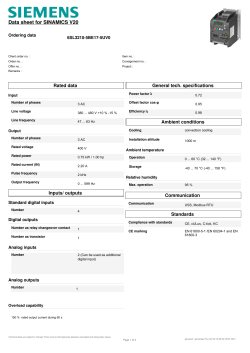


© Copyright 2026