
A pressure calibration method for a portable wide
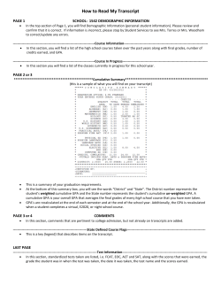
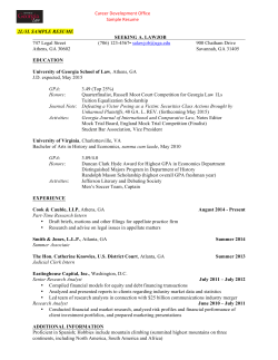
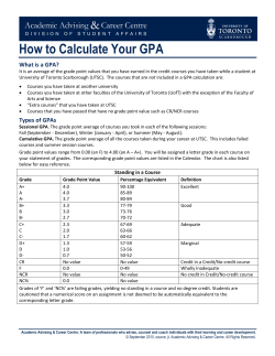
Chin. Phys. B Vol. 23, No. 11 (2014) 110701
A pressure calibration method for a portable wide-access
“panoramic” cell∗
Fang Lei-Ming(房雷鸣)† , Wang Yun(王 云), Chen Xi-Ping(陈喜平), Sun Guang-Ai(孙光爱),
Chen Bo(陈 波), and Peng Shu-Ming(彭述明)
Institute of Nuclear Physics and Chemistry, China Academy of Engineering Physics, Mianyang 621900, China
(Received 9 April 2014; revised manuscript received 20 May 2014; published online 21 October 2014)
A simple and convenient pressure calibration method is developed for a newly designed portable wide-access
‘panoramic’ cell. This cell is adapted to angle-dispersive-mode high-pressure in situ neutron diffraction of reactor neutron
sources. This pressure calibration method has established a relationship between the cell pressure and the anvil displacement (gasket compression) based on the fixed-point calibration technique. By employing TiZr gasket with a thickness of
3 mm and WC anvil with a culet of 4 mm diameter, the average anvil displacements are 1.31 mm and 2.22 mm for Bi phase
transitions (2.55 GPa and 7.7 GPa), and 1.85 mm for Ba phase transitions (5.5 GPa), respectively. In this pressure range, the
pressure increases quickly with decreasing gasket thickness, and undergoes a linear increase with the anvil displacement.
By extrapolating the calibration curve, the cell pressure will achieve 10 GPa when the anvil displacement is around 2.5 mm.
Keywords: pressure calibration, neutron diffraction, phase transition
PACS: 07.35.+k, 47.80.Fg, 61.05.F−, 61.50.Ks
DOI: 10.1088/1674-1056/23/11/110701
1. Introduction
Neutrons are complementary to X-rays because they can
specially probe nuclei, magnetic structure, are sensitive to
light atoms, and have high penetrating power. Thus, in situ
neutron diffraction experiments under high pressure can play
a key role in obtaining structural information on various materials. A toroid-type high-pressure apparatus with a so-called
‘Paris-Edinburgh (PE) press’ [1] is a standard high-pressure device in this domain. It can generate pressures of up to 10 GPa
on sample volumes of ∼ 100 mm3 , and pressures up to 30 GPa
on sample volumes of ∼ 30 mm3 . [2,3] This device is adapted to
time-of-flight (TOF) techniques at a fixed scattering angle, and
achieves enormous success in high-pressure structural studies
about the pulsed neutron sources, such as the neutron facilities ISIS in the United Kingdom or LANSCE in the United
States. In contrast to the energy-dispersive mode in pulse neutron facilities used by TOF spectroscopy, diffraction patterns
are usually collected with the angle-dispersive mode in continuous neutron sources, such as reactor based facilities. However, there is some inconveniences to making progress with
this technique. First, the opening window for diffraction is
limited by the geometry of high pressure devices, and thus it
is difficult to cover the wide angle range needed for the angular dispersion method. Secondly, the strong contamination of
the pattern is made by the signal from the anvils because of the
need to ensure large sample volumes. More recently, to combine high pressures and large sample volumes, Xu [4,5] and his
colleagues have developed a panoramic type moissanite (SiC)
anvil cell (MAC) that can readily generate pressure to 50 GPa,
which is significantly higher than that generated by conventional Paris–Edinburgh cells. However, its sample volume is
much smaller than that of a PE cell, although the sample volumes are many orders larger in magnitude than those available
in diamond anvil cells (DAC). [6] MAC is driven by hand force,
the same as DAC, thereby it is convenient to bring them to the
X-ray/neutron beamlines. Analogously, we have designed a
portable panoramic type opposed anvil cell with a wide opening window, large sample volume, and mild higher pressure,
which is adapted to be employed at reactor neutron sources for
angle-dispersive mode diffraction. [7]
In general, the cell pressure of high-pressure devices can
be determined by measuring the EOS of pressure markers,
such as Pt, Ag, Au, NaCl, MgO, etc., via in situ X-ray/neutron
diffraction techniques. [8] Another conventional pressure calibration is to measure the fluorescence spectra of ruby grains
while applying high pressure. [9,10] This method is adapted to
DAC or MAC, which profits from the fact that the fluorescence
spectra can pass through the diamond or moissanite anvils.
On the other hand, the pressure calibration for a large volume
press generally uses the fixed-point calibration technique. This
method establishes the relationship of the cell pressure and applied load (or hydraulic oil pressure) prior to the high pressure
experiment by measuring the phase transition of some standard materials, such as bismuth, thallium, cesium, barium, etc.
Thereby, the accurate and repeatable determination of an applied load is necessary for this method. Generally, it is difficult
to measure the applied load directly for ‘hand-force’ type cells
due to the discontinuous force applied, such as our designed
∗ Project
supported by the National Natural Science Foundation of China (Grant Nos. 91126001, 11105128, and 51231002).
author. E-mail: [email protected]
© 2014 Chinese Physical Society and IOP Publishing Ltd
http://iopscience.iop.org/cpb http://cpb.iphy.ac.cn
† Corresponding
110701-1
Chin. Phys. B Vol. 23, No. 11 (2014) 110701
panoramic type opposed anvil cell where pressure is generated
by turning screws. In this paper, we develop a simple and convenient pressure calibration based on the fixed-point calibration technique by monitoring the anvil displacement (gasket
compression) of our portable wide-access ‘panoramic’ cell.
2. Experimental details
2.1. Geometry of the cell
The newly developed cell designed for angle-dispersive
neutron diffraction is a wide-access ‘panoramic’ cell. Two opposed anvils are central and aligned in a piston cylinder, as
illustrated in Fig. 1. Eight screws and a lot of disc springs
are used to lock-up pressure. The load is applied by turning
screws, which disengage the setting from the bulky hydraulic
ram and loading frames, and it is convenient to bring them
to the neutron beamlines. The entire setting has a mass of
10 kg and a size of Φ 85 mm × 100 mm, which ensures that it
is portable and lightweight. Two symmetrical windows, each
with 135◦ equatorial and 68◦ azimuthal opening angles, are
cut open at the equatorial position of the outer cylinder body.
PCD (polycrystal diamond) or SiC anvils are employed to generate higher pressure, while WC (Tungsten carbide) is used to
generate a slightly lower pressure range.
This cell is mainly intended for direct observation of the
sample under pressure, as well as neutron diffraction. The key
features of this new cell design are: to enlarge the diffraction windows to satisfy the angle-dispersive mode in the continuous neutron sources; to lock-up pressure on two opposed
anvils with piston-cylinder alignment by turning screws; and,
to adapt the PCD anvil to ensure both large sample volumes
and high pressure.
load
micrometer
Dl
10 mm
Fig. 1. Schematic drawing of the portable wide-access ‘panoramic’ cell.
The load is applied by turning screws. A micrometer was employed to
determine the anvil displacement (gasket compression) by measuring
the spacing between the rear tables of cell.
2.2. New calibration method of cell pressure
The fixed-point calibration technique was originally developed by Bridgman. [11] Some materials undergoing phase
transitions can be expressed by abrupt changes in electrical resistance at a certain pressure. [12] When these transitions are
observed to occur, the corresponding force on the anvils is
monitored and a calibration plot of cell pressure versus press
load is established.
Since in our case the force is applied by screws, the direct measurement of the press load is rather laborious. After the load is applied step by step, the gasket thickness decreases from an original value of 3 mm to ∼ 0.5 mm. However, the measurement of anvil displacement (gasket compression) is advisable. [13] The linear relationship of applied
load and squeezed displacement of gasket was proposed by
Dunstan. [14] Thus, we propose a calibration method by establishing a relationship between press load and gasket compression. This calibration method has a simple procedure before
performing high-pressure experiments, which can ensure the
efficiency of the cell, select an optimal value of relationship
between the size of anvil culets and thickness of gasket, and
establish a simple empirical rule for estimating the press load
by measuring the gasket compression.
Taking into account that the sub-millimeter scale of gasket compression is enough for the use of a micrometer (the
measurement accuracy is 0.001 mm), [15] a micrometer is used
to determine the anvil displacements in this study, which measures the spacing between the rear (supporting) tables of the
cell, as shown in the Fig. 1.
2.3. Cell assembly
In this experiment, the cell pressures were calibrated by
using the resistance measurement method with Bi and Ba.
This method is followed by a careful assembling. The WC
anvil, which has a cone-shaped flat culet of Φ 4 mm, is employed in this study. The anvil is cut with 10◦ slope and
is pushed into the steel reinforcement ring. Baked (700 ◦ C,
30 min) natural pyrophyllite is used as gasket, measuring
initially 3 mm in thickness. A null-scattering Ti/Zr alloy
(67.7 mol% Ti, 32.2 mol% Zr) is located around the pyrophyllite as an additional support. We used copper foil (0.01 mm
thickness) as electrodes for the electrical connection and used
electrical tape as an insulator to separate the copper foil from
the Ti/Zr alloy. The details for the connection of Bi and Ba
wires, and copper foils are shown in Fig. 2. During the experiments, we simultaneously recorded the anvil displacement and
the resistances of Bi and Ba, while applying the load step by
step.
110701-2
Chin. Phys. B Vol. 23, No. 11 (2014) 110701
change at 1.850(9) mm for Ba was observed, which corresponds to I–II (5.5 GPa) phase transitions. [18] The changing
trends of the resistance of Bi and Ba are consistent with previous reports. [19] Figure 3 is a typical measurement of resistance
changes of Bi and Ba as a function of the anvil displacement.
The anvil displacement ∆l corresponds to the compression of
the gasket. Zero of ∆l implies the contact position of the anvils
against the initial gasket, and a maximum ∆l of 3.00 mm for
3.00-mm-thickness gasket was used in this experiment.
copper foil
anvil
Table 1. Measurement results of anvil displacements.
Bi or Ba
TiZr
Bi I–II (2.55 GPa)
Ba I–II (5.5 GPa)
Bi III–V (7.7 GPa)
pyrophyllite
Bi
Anvil displacements/mm
1
2
3
1.315 1.326
1.302
1.850 1.842
1.859
2.221 2.210
2.226
Average
Error
1.314
1.850
2.219
0.012
0.009
0.008
2.4
6
Bi I-II: 2.55 GPa
Ba
3. Pressure-induced phase transition of ZrW2 O8
Upon applying pressure at room temperature, the cubic
α-ZrW2 O8 transforms into a quenchable orthorhombic phase
λ -ZrW2 O8 . This phase transition takes place at a pressure of
0.2 GPa. [16] As the pressure further increases to 1.5–3.5 GPa,
λ -ZrW2 O8 gradually becomes amorphous, and amorphous
ZrW2 O8 is also irreversible upon decompression. [17]
An additional experiment is conducted with α-ZrW2 O8
(Alfa, 99.7%, −200 mesh) used as starting material. A 3mm-thickness Ti/Zr alloy gasket with a Φ 2 mm hole for assembling sample, and the WC anvil with Φ 4 mm culet were
used as described in the previous section. Four experiments
were performed, with the anvil displacement being 0.5 mm,
0.85 mm, 1.0 mm, and 1.5 mm, respectively. The recovered samples were characterized by X-ray diffraction (Philips
X’pert diffractometer).
4. Results and discussion
The electrical resistances of Bi and Ba, and the anvil displacements have been simultaneously measured as the load
was applied step by step. We repeated the measurements three
times with the same anvil and the same size of gasket. The
results are shown in Table 1. Two discontinuities of Bi resistance were observed at 1.314(12) mm and 2.219(8) mm of
anvil displacements, which correspond to I–II (2.55 GPa) and
III–V (7.7 GPa) phase transitions, respectively, and one abrupt
Resistance of Bi/W
Fig. 2. (color online) Sample assembly for Bi and Ba resistance measurement.
5
Ba I-II: 5.5 GPa
2.1
4
1.8
3
Bi III-V: 7.7 GPa
1.5
2
1.2
0.9
1.00
1
1.25
1.50
1.75
2.00
2.25
2.50
Resistance of Ba/W
insulator
0
2.75
Dl/mm
Fig. 3. Resistance changes of Bi (circle) and Ba (square) as a function of the
anvil displacement. The lines are used as guides for the eye.
Figure 4 shows the XRD patterns of the recovered
ZrW2 O8 products. Figures 4(a)–4(d) show different applied
loads, corresponding to various anvil displacements (∆l) of
0.50 mm, 0.85 mm, 1.00 mm, and 1.50 mm, respectively.
As we know, the pressure of α-ZrW2 O8 transforming to λ ZrW2 O8 starts from 0.2 GPa, and then gradually becomes
amorphous from 1.5 to 3.5 GPa. Only α-ZrW2 O8 peaks
were observed when ∆l is at 0.50 mm, indicating that the
cell pressure is below 0.2 GPa at this load (anvil displacement) (Fig. 4(a)). When the anvil displacements are 0.85
and 1.0 mm, intense peaks of λ -ZrW2 O8 appear, as shown
in Figs. 4(b) and 4(c). This indicates that the pressure is between 0.2 GPa and 1.5 GPa at these loads. The percentage
of λ -ZrW2 O8 in Fig. 4(c) obviously increases compared with
Fig. 4(b), which should be attributed to the increase of the
pressure. When ∆l is at 1.5 mm, the peaks of α-ZrW2 O8 disappear completely and the peaks of λ -ZrW2 O8 become broad
and considerably decrease its intensity, suggesting that the cell
pressure reaches up to 3.5 GPa or above.
110701-3
Chin. Phys. B Vol. 23, No. 11 (2014) 110701
XRD
•
•
(d)
α-Zr2WO8
• γ-Zr2WO8
•
Intensity
•
(c)
•
(b)
•
(a)
15
20
25
2θ/(O)
30
35
Fig. 4. XRD patterns of recovered ZrW2 O8 products from different
anvil displacements: (a) 0.50 mm, (b) 0.85 mm, (c) 1.00 mm, and (d)
1.50 mm, respectively.
The pressure calibration curves can be obtained based on
phase transition of Bi and Ba, as shown in Fig. 5. The result
shows that the pressure depends linearly on the anvil displacement, and it has a positive slope (∼ 5.7 GPa/mm). At a lower
pressure range (0–1.5 GPa), the pressure increases slowly before the anvil displacement reaches 1.0 mm. Furthermore, the
result shows that an anvil displacement is required before any
pressure is generated. According to the XRD results of recovered ZrW2 O8 , until the displacement achieves 0.5 mm, the
pressure is still below 0.2 GPa. On the basis of an extrapolation of the curve, at an anvil displacement of about 2.5 mm, the
pressure can achieve about 10 GPa. However, further squeezing the gasket does not produce a significant increase in the
cell pressure.
10
Pressure/GPa
8
Bi III-V: 7.7 GPa
6
Ba I-II: 5.5 GPa
4
2
amorphous Zr2WO8
Bi I-II: 2.55 GPa
γ-Zr2WO8
0
α-Zr2WO8
0
0.5
1.0
1.5
2.0
2.5
3.0
Dl/mm
Fig. 5. Pressure calibration curves of cell pressure versus anvil displacement. The solid squares are determined anvil displacements of
Bi and Ba by resistance measurement. The opened circle, opened diamond, and opened triangle are amorphous ZrW2 O8 , λ -ZrW2 O8 , and
α-ZrW2 O8 , respectively.
According to the operation theory of the gasket in the diamond anvil cell (DAC) by Dunstan, [14] , the hydrostatic pressure can be estimated by the following relation:
2k r0 rg σn = nk + √
−
,
t
3 t
where σn is the normal stress on the gasket surface, k is the
yield strength of the gasket material, r0 , rg , and t are the sample hole radius, anvil culet radius, and gasket thickness, respectively. The hydrostatic pressure is equal to σn , if the cell
pressure is assumed to be in a hydrostatic condition. Thus,
the plateau in pressure generating is most likely related to the
gasket aspect ratio, anvil culet diameter, and the yield strength
of the gasket. For an anvil displacement below about 1.0 mm,
the pressure generating is slow because of some sample leaking that occurs at the beginning of the compression. In order to avoid this, the anvil faces against the gasket should
be tightly sealed; namely, prepared preindentation gasket is
generally necessary. [14] When the anvil displacement is above
1.0 mm, the pressure increases quickly with the decrease in
gasket thickness, and then increases linearly as a function of
anvil displacement. In this pressure range, the gasket works in
the thick gasket regime, which means that the surface layers
of the gasket remain stationary on the anvil face due to the fact
that the friction between the gasket and anvil exceeds k (yield
strength of the gasket). On the other hand, outside this pressure range, slipping between the gasket and the anvil prevails
and the gasket undergoes an outward plastic extrusion and,
consequently, the increase in pressure was never observed.
In this case, the gasket is in an unstable regime and further
squeezing does not induce a pronounced pressure increase. [20]
This means that a plateau in pressure generating occurs.
5. Conclusion
In order to adapt to angle-dispersive diffraction in reactor neutron facilities, we designed a panoramic type opposed
anvil cell with wide opening window. This portable device
can generate and lock the pressure by turning screws, which is
convenient way to bring it to neutron beamlines. WC (tungsten carbide), PCD (polycrystal diamond), and SiC can be employed as anvil material depending on the highest pressure
needed. Because it is difficult to measure the applied hand
force (turning screws by hand) directly, we develop a simple
and convenient pressure calibration based on the fixed-point
calibration technique. This method can determine the pressure by monitoring the anvil displacement. In this study, we
observe the abrupt changes of resistance of Bi and Ba at the
anvil displacement of 1.31 mm (Bi I–II), 2.22 mm (Bi III–V),
and 1.85 mm (Ba I–II), respectively, by using 3-mm-thickness
gasket with a 2mm diameter hole and WC anvil with a culet
diameter of 4 mm. According to XRD result of the recovered
ZrW2 O8 samples, the pressure increased slowly with increasing anvil displacement up to around 1.0 mm. When the anvil
displacement is above 1.0 mm, the pressure increases quickly
with the decrease in gasket thickness, and undergoes a linear
increase as a function of the anvil displacement due to the fact
that the gasket works in the thick gasket regime, as explained
110701-4
Chin. Phys. B Vol. 23, No. 11 (2014) 110701
by Dunstan [14] and Bonetti. [20] On the basis of extrapolation of
the curve, with a displacement at about 2.5 mm, the cell pressure can achieve around 10 GPa. However, a plateau in pressure generating will occur because further squeezing does not
induce a pronounced pressure increase, although the plateau
pressure was not determined in this work.
Acknowledgment
The authors thank Prof. Duanwei He (Institute of Physics,
Chinese Academy of Sciences) for the fruitful discussion.
References
[1] Besson J M, Nelmes R J, Hamel G, Loveday J S, Weill G and Hull S
1992 Physica B 180 907
[2] Klotz S, Besson J M, Hamel G, R J Nelmes, Loveday J S, Marshall W
G and Wilson R M 1995 Appl. Phys. Lett. 66 1735
[3] Klotz S, Str¨assle Th, Rousse G, Hamel G and Pomjakushin V 2005
Appl. Phys. Lett. 86 031917
[4] Xu J and Mao H K 2000 Science 290 783
[5] Xu J, Mao H K, Hemley R J and Hines E 2004 Rev. Sci. Instr. 75 1034
[6] Hui B, He D, Lu Y, Chen X, Zhang Y, Sun G and Chen B 2013 Chin.
J. High Press. Phys. 27 517 (in Chinese)
[7] Fan D W, Wei S Y and Xie H S 2013 Chin. Phys. B 22 010702
[8] Jing Q M, Wu Q, Liu L, Bi Y, Zhang Y, Liu S G and Xu J A 2012 Chin.
Phys. B 21 106201
[9] Mao H K, Xu J and Bell P M 1986 J. Geophys. Res. 91 4673
[10] Liu L, Bi Y and Xu J A 2013 Chin. Phys. B 22 056201
[11] Bridgman P W 1952 Proc. Am. Acad. Arts Sci. 81 165
[12] Decker D L, Bassett W A, Merrill L, Hall H T and Barnett J D 1972 J.
Phys. Chem. Ref. Data 1 773
[13] Timofeev Y A and Utyuzh A N 2003 Instr. Exp. Tech. 46 721
[14] Dunstan D J 1989 Rev. Sci. Instrum. 60 3789
[15] Johansen P G 1989 Simple Molecular System at Very High Density
(New York: Eds., Plenum.) p. 299
[16] Evans J S O, Hu Z, Jorgensen J D, Argyriou D N, Short S and Sleight
A W 1997 Science 275 61
[17] Perottoni C A and da Jornada J A H 1998 Science 280 886
[18] Bean V E, Akimoto S, Bell P M, Block S, Holzapfel W B, Manghnani
M H, Nicol M F and Stishov S M 1986 Physica B 139 52
[19] Fang L, He D, Chen C, Ding L and Luo X 2007 High Press. Res. 27
367
[20] Bonetti M and Calmettes P 2005 Rev. Sci. Instrum. 76 043903
110701-5


© Copyright 2026