
Rosemount 148 Temperature Transmitter Datasheet
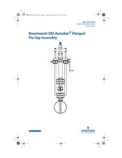
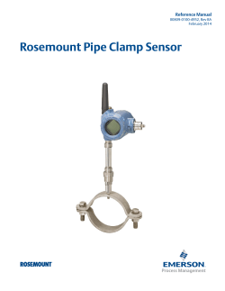
Product Data Sheet January 2015 00813-0100-4148, Rev GB Rosemount 148 Temperature Transmitter Basic temperature transmitter offers a cost-effective solution for temperature monitoring points. Standard transmitter design provides flexible and reliable performance in process environments. Experience lower overall installation costs when compared to wiring sensor directly, reducing the need for expensive extension wires and multiplexers. PC-based HART® configuration interface delivers a programmer, cables, and the software needed for transmitter configuration. Explore the benefits of a complete point solution from Rosemount Temperature. Rosemount 148 January 2015 Rosemount 148 Temperature Transmitter Basic temperature transmitter offers a cost-effective solution for temperature monitoring points DIN B style head mount transmitter Variety of DIN B enclosure options 4-20 mA analog protocol Single sensor capability with universal sensor inputs (RTD, T/C, ohms) PC-based configuration Standard transmitter design provides flexible and reliable performance in process environments Offers improved measurement accuracy and reliability over direct-wiring a sensor to the digital control system for a lower overall installation cost One-year stability rating reduces maintenance costs PC-based configuration interface delivers a programmer, cables, and the software needed for transmitter configuration Compensation for ambient temperature enhances transmitter performance Explore the benefits of a complete point solution from Rosemount Temperature Measurement An “Assemble To Sensor” option enables Emerson to provide a complete point temperature solution, delivering an installation-ready transmitter and sensor assembly. Emerson offers a selection of RTDs, thermocouples, and thermowells that bring superior durability and Rosemount reliability to temperature sensing, complementing the Rosemount Transmitter portfolio. Contents Ordering Information . . . . . . . . . . . . . . . . . . . . . . . . . . . . . . . 4 Dimensional Drawings . . . . . . . . . . . . . . . . . . . . . . . . . . . . . . 10 Rosemount 148 Configuration Interface Specifications . . . . . 6 Product Certifications . . . . . . . . . . . . . . . . . . . . . . . . . . . . . . 11 Transmitter Specifications . . . . . . . . . . . . . . . . . . . . . . . . . . . . 7 2 www.rosemount.com January 2015 Rosemount 148 Experience global consistency and local support from numerous worldwide Rosemount Temperature manufacturing sites World-class manufacturing provides globally consistent product from every factory and the capacity to fulfill the needs of any project, large or small. Experienced Instrumentation Consultants help select the right product for any temperature application and advise on best installation practices. An extensive global network of Emerson service and support personnel can be on-site when and where needed. Looking to measure more temperature points in a cost effective way? Consider a wireless temperature solution. The Rosemount 148 Wireless Temperature Transmitter is solid performing, yet economical. For temperature installations that require reliable measurement and can benefit from HART functionality, the Rosemount 148 Temperature Transmitter is a cost-effective solution. www.rosemount.com 3 Rosemount 148 January 2015 Ordering Information The Rosemount 148 Temperature Transmitter has a standard transmitter design that provides reliable performance in process environments. Transmitter features include: 4-20 mA Analog Output Variety of DIN B enclosure options 3-Point Calibration Certificate (Option Code Q4) Assemble to Sensor option (Option Code XA) Specification and selection of product materials, options, or components must be made by the purchaser of the equipment. See page 8 for more information on Material Selection. Table 1. Rosemount 148 PC-Programmable Temperature Transmitter Ordering Information ★ The Standard offering represents the most common options. The starred options (★) should be selected for best delivery. __The Expanded offering is subject to additional delivery lead time. Model Product description 148 PC Programmable Temperature Transmitter Transmitter type H ★ DIN B Head Mount Transmitter output N ★ Analog Output Product certifications Enclosure option codes permitted I5 FM Intrinsic Safety and Class 1, Division 2 A, B, U, G, H, N ★ FM Explosion-Proof A, U, G, H ★ E5(1) FM Intrinsic Safety, Explosion-Proof, and Class 1, Division 2 A, U, G, H ★ I6 CSA Intrinsic Safety and Class 1, Division 2 A, B, U, G, H, N ★ K6(1) CSA Intrinsic Safety, Explosion-Proof, and Class 1, Division 2 A, U, G, H ★ I1 ATEX Intrinsic Safety All enclosures ★ K5 (1) E1 ATEX Flameproof A, U, G, H ★ N1(1) ATEX Type n with enclosure A, U, G, H ★ NC ATEX Type n Component without enclosure N ★ ND ATEX Dust A, U, G, H ★ I7 IECEx Intrinsic Safety All enclosures ★ E7(1) IECEx Flameproof and Dust A, U, G, H ★ N7 IECEx Type n with enclosure A, U, G, H ★ NG IECEx Type n without enclosure N ★ KM Technical Regulations Customs Union (EAC) Flameproof, Intrinsic Safety A, U, G, H ★ IM Technical Regulations Customs Union (EAC) Intrinsic Safety All enclosures ★ EM Technical Regulations Customs Union (EAC) Flameproof A, U, G, H ★ NA No approvals All enclosures ★ (1) (1) (1) 4 www.rosemount.com January 2015 Rosemount 148 Table 1. Rosemount 148 PC-Programmable Temperature Transmitter Ordering Information ★ The Standard offering represents the most common options. The starred options (★) should be selected for best delivery. __The Expanded offering is subject to additional delivery lead time. Enclosure options Material IP rating A Connection Head Aluminum IP68 ★ U Universal Head (Junction Box) Aluminum IP68 ★ B BUZ Head Aluminum IP65 ★ C BUZ Head Polypropylene IP65 ★ N No Enclosure N/A N/A ★ G Connection Head SST IP68 H Universal Head (Junction Box) SST IP68 S Sanitary Connection Head, DIN B Polished SST IP66 F Sanitary Connection Head, DIN A Polished SST IP66/IP68 Conduit entry size 1 M20 ⫻ 1.5 (CM20) ★ 2 1 /2-14 in. NPT ★ 0 No Enclosure ★ Options (include with selected model number) Alarm level configuration A1 NAMUR alarm and saturation levels, high alarm ★ CN NAMUR alarm and saturation levels, low alarm ★ Calibration certificate Q4 ★ Calibration Certificate (3-point Calibration) Line filter F6 ★ 60 Hz Line Voltage Filter External ground option (available w/enclosures U, H) G1 ★ External Ground Lug Assembly Cover chain option (available w/enclosures U, H) G3 ★ Cover Chain Cable gland option G2 Cable Gland–Explosion Proof–7.5 mm - 11.9 mm ★ G4 Cable Gland–Explosion Proof, Thin Wire - 3.0 mm - 8.0 mm ★ Conduit electrical connector GE GM M12, 4-pin, Male Connector (eurofast®) ★ ® A size Mini, 4-pin, Male Connector (minifast ) ★ Assemble to options XA Sensor Specified Separately and Assembled to Transmitter Typical model number: ★ 148 H N I5 U1 A1 XA (1) Approval Codes E1, N1, N7, ND, E5, K5, K6, and E7 require an enclosure. www.rosemount.com 5 Rosemount 148 January 2015 Rosemount 148 Configuration Interface Specifications Configuration software(1) The Rosemount 148 PC-based configuration software for the Rosemount 148 allows comprehensive configuration of the transmitters. Used in conjunction with various Rosemount or user-supplied hardware modems, the software provides the tools necessary to configure the 148 Transmitters including the following parameters: Process Variable Sensor Type Number of Wires Engineering Units Transmitter Tag Information Damping Alarming Parameters USB HART modem and software (Part #: 00148-1601-0003) USB (Universal Serial Bus) HART modem Customer must provide separate loop power supply and resistor. Requires PC with USB port Suitable for use with powered loops Figure 1. Rosemount 148 Transmitter Accessories A B Configuration hardware The 148 Configuration Interface has 3 hardware options as follows: Software only (Part #: 00148-1601-0002) Customer must provide appropriate communications hardware (modem, power supply, etc.). Serial HART modem and software (Part #: 00148-1601-0004) Serial HART modem Customer must provide separate loop power supply and resistor. Requires PC serial port Suitable for use with powered loops (1) 6 C A. Mounting Hardware B. Transmitter C. Rail Clip Table 2. Rosemount 148 Transmitter Accessories External Ground Screw Assembly Kit 00644-4431-0001 Kit, Hardware for Mounting a 148 to a DIN Rail (see left picture-top hat rail, symmetric) 00248-1601-0001 Snap Rings Kit (used for assembly to DIN Plate Style sensor) 00644-4432-0001 The Rosemount configuration software is compatible with Microsoft® Windows™ XP, Windows 7 32-bit and Windows 7 64-bit. It is not compatible with Windows NT and Windows 2000. www.rosemount.com January 2015 Rosemount 148 Transmitter Specifications Functional specifications Turn-on time Inputs Performance within specifications is less than 5.0 seconds after power is applied to the transmitter, when damping value is set to zero seconds. User-selectable; sensor terminals rates to 42.4 Vdc. See “Transmitter accuracy and ambient temperature effects” on page 8 for sensor options. Update rate Output Less than 0.5 seconds 2-wire 4–20 mA, linear with temperature or input Damping Isolation 32 seconds maximum, 5 seconds default. Input/Output isolation tested to 500 Vac rms (707 Vdc) at 50/60 Hz. Recommended minimum measuring span 18 °F (10 °C) Supply voltage DC Software detected failure mode Standard: 12 to 35 V The values at which the transmitter drives its output in failure mode depends on device configuration. The device can be configured to meet NAMUR-compliant (NAMUR recommendation NE 43) operation. The values for standard and NAMUR-compliant operation are as follows: Intrinsic Safety: 12 to 28 V Minimum voltage across terminals 12 Vdc Humidity limits Table 3. Operation Parameters 0 - 95% relative humidity, non-condensing Standard(1) NAMUR NE43-Compliant(1) Linear Output: 3.9 ≤ I ≤ 20.5 3.8 ≤ I ≤ 20.5 Fail High: 21 ≤ I ≤ 23 (default) 21 ≤ I ≤ 23 (default) Fail Low: I ≤ 3.75 I ≤ 3.6 NAMUR recommendations The 148 meets the following NAMUR recommendations: NE 21 - Electromagnetic compatibility (EMC) for Process and Laboratory Apparatus NE 43 - Standard of the signal level breakdown information of digital transmitters (1) Measured in milliamperes. Transient protection The optional Rosemount 470 Transient Protector prevents damage from transients induced by lightning, welding, heavy electrical equipment, or switch gears. Refer to the 470 Product Data Sheet (document number 00813-0100-4191) for more information. Certain hardware failures, such as microprocessor failures, will always drive the output to greater than 23 mA. Temperature limits Operating Limit -40 to 185 °F (-40 to 85 °C) Storage Limit -58 to 248 °F (-50 to 120 °C) www.rosemount.com 7 Rosemount 148 January 2015 Performance specifications CE mark Material selection The 148 meets all of the requirements listed under IEC 61326: Amendment 1, 2006. Emerson provides a variety of Rosemount product with various product options and configurations including materials of construction that can be expected to perform well in a wide range of applications. The Rosemount product information presented is intended as a guide for the purchaser to make an appropriate selection for the application. It is the purchaser’s sole responsibility to make a careful analysis of all process parameters (such as all chemical components, temperature, pressure, flow rate, abrasives, contaminants, etc.), when specifying product, materials, options and components for the particular application. Emerson Process Management is not in a position to evaluate or guarantee the compatibility of the process fluid or other process parameters with the product, options, configuration or materials of construction selected. Power supply effect Less than ±0.0055 of span per volt Vibration effect The 148 is tested to the following specifications with no effect on performance: Frequency Vibration 10 to 60 Hz 0.21 mm displacement 60 to 2000 Hz 3 g peak acceleration Stability For RTD and thermocouple inputs, the transmitter will have a stability of ±0.15% of reading or 0.15 °C (whichever is greater) for twelve months. EMC (Electromagnetic Compatibility) NAMUR NE21 standard The 148 meets the requirements for NAMUR NE21 Rating. Sensor connections Susceptibility Parameter Influence ESD 6 kV contact discharge 8 kV air discharge None Radiated 80 – 1000 MHz at 10 V/m AM None Burst 1 kV for I.O. None Figure 2. 148 Sensor Connections Diagram Surge 0.5 kV line–line 1 kV line–ground (I.O. tool) None Conducted 150 kHz to 80 MHz at 10 V None (1) 1 2 3 4 1 2 3 4 1 2 3 4 1 2 34 2-wire RTD and ⍀ 3-wire RTD and ⍀(1) 4-wire RTD and ⍀ T/C Rosemount Inc. provides 4-wire sensors for all single element RTDs. You can use these RTDs in 3-wire configurations by leaving the unneeded leads disconnected and insulated with electrical tape. Transmitter accuracy and ambient temperature effects Note The accuracy and ambient temperature effect is the greater of the fixed and percent of span values (see example below). Table 4. 148 Transmitter Input Options, Accuracy, and Ambient Temperature Effects Sensor Transmitter input ranges(1) Temperature effects per 1.0 °C (1.8 °F) change in ambient temperature(2)(3) Accuracy 2-, 3-, 4-wire RTDs °C °F Fixed % of span Fixed % of span Pt 100(4) (a = 0.00385) –200 to 850 –328 to 1562 0.3 °C (0.54 °F) ±0.15 0.009 °C (0.016 °F) ±0.006 Pt 100(5) (a = 0.003916) –200 to 645 –328 to 1193 0.3 °C (0.54 °F) ±0.15 0.009 °C (0.016 °F) ±0.006 Ni 120(6) –70 to 300 –94 to 572 0.2 °C (0.36 °F) ±0.15 0.006 °C (0.011 °F) ±0.006 Cu 10(7) –50 to 250 –58 to 482 3 °C (5.40 °F) ±0.15 0.09 °C (0.16 °F) ±0.006 8 www.rosemount.com January 2015 Rosemount 148 Table 4. 148 Transmitter Input Options, Accuracy, and Ambient Temperature Effects Sensor Transmitter input ranges(1) Temperature effects per 1.0 °C (1.8 °F) change in ambient temperature(2)(3) Accuracy Thermocouples(8) Type B(9)(10) Type J (9) 100 to 1820 212 to 3308 2.3 °C (4.05 °F) ±0.15 0.084 °C (0.150 °F) ±0.006 –180 to 760 –292 to 1400 0.8 °C (1.35 °F) ±0.15 0.03 °C (0.054 °F) ±0.006 (9)(11) –180 to 1372 –292 to 2502 0.8 °C (1.35 °F) ±0.15 0.03 °C (0.054 °F) ±0.006 (9) –200 to 1300 –328 to 2372 1.2 °C (2.16 °F) ±0.15 0.03 °C (0.054 °F) ±0.006 Type R(9) 0 to 1768 32 to 3214 1.8 °C (3.24 °F) ±0.15 0.09 °C (0.16 °F) ±0.006 (9) 0 to 1768 32 to 3214 1.5 °C (2.70 °F) ±0.15 0.09 °C (0.16 °F) ±0.006 1.1 ohm ±0.15 0.042 ohm ±0.009 Type K Type N Type S 2-, 3-, 4-wire Ohm Input 0 to 2000 ohms (1) Input ranges are for transmitter only. Actual sensor (RTD or Thermocouple) operating ranges may be more limited. (2) Change in ambient is with reference to the calibration temperature of the transmitter at 68 °F (20 °C) from factory. (3) Ambient temperature effect specification valid over minimum temperature span of 28°C (50°F) (4) IEC 751, 1995. (5) JIS 1604, 1981. (6) Edison Curve No. 7. (7) Edison Copper Winding No. 15. (8) Total accuracy for thermocouple measurement: sum of accuracy +0.5 °C. (9) NIST Monograph 175, IEC 584. (10) Fixed accuracy for NIST Type B is ±5.4 °F (±3.0 °C) from 212 to 572 °F (100 to 300 °C). (11) Fixed accuracy for NIST Type K is ±1.3 °F (±0.7 °C) from -292 to -130 °F (-130 to -90 °C). Transmitter accuracy example When using a Pt 100 (a = 0.00385) sensor input with a 0 to 100 °C span, use the greater of the two calculated values. In this case, the accuracy would be +/-0.3 °C. Transmitter temperature effects example Transmitters can be installed in locations where the ambient temperature is between –40 and 85 °C (–40 and 185 °F). In order to maintain excellent accuracy performance, each transmitter is individually characterized over this ambient temperature range at the factory. When using a Pt 100 (a = 0.00385) sensor input with a 0–100 °C span at 30 °C ambient temperature: Temperature Effects: 0.009 °C x (30 - 20) = 0.09 °C Total transmitter error Worst Case Transmitter Error: Accuracy + Temperature Effects = 0.3 °C + 0.09 °C = 0.39 °C Total Probable Transmitter Error: www.rosemount.com 0.3 2 + 0.09 2 = 0.31°C 9 Rosemount 148 January 2015 Dimensional Drawings Figure 3. Rosemount 148 Temperature Transmitter Top view Side view 12.9 (0.51) 24.5 (0.97) 33 (1.3) 44 (1.7) DIN Rail mounting kit 50 (1.97) Dimensions are in millimeters (inches). 10 www.rosemount.com January 2015 Rosemount 148 Product Certifications Approved Manufacturing Locations Special Conditions for Safe Use (X): 1. When no enclosure option is selected, the Model 148 Temperature Transmitter shall be installed in an enclosure meeting the requirements of ANSI/ISA S82.01 and S82.03 or other applicable ordinary location standards. Rosemount Inc. - Chanhassen, Minnesota, USA Rosemount Temperature GmbH - Germany Emerson Process Management Asia Pacific - Singapore 2. No enclosure or Buz Head option cannot be selected to maintain a Type 4X rating. European Directive Information 3. Enclosure option must be selected to maintain a Type 4 Rating. A copy of the EC Declaration of Conformity can be found at the end of the Quick Start Guide. The most recent revision of the EC Declaration of Conformity can be found at www.rosemount.com. I6 CSA Intrinsic Safety and Division 2 Certificate: 1091070 Standards: CAN/CSA C22.2 No. 0-M90, CSA Std. C22.2 No. 25-1966, CAN/CSA C22.2 No. 94-M91, CAN/CSA C22.2 No. 157-92, CSA C22.2 No. 213-M1987, C22.2 No 60529-05 Markings: IS CL I, DIV 1 GP A, B, C, D when installed per Rosemount drawing 00248-1056; Suitable for CL I DIV 2 GP A, B, C, D when installed per Rosemount drawing 00248-1055; T6(-50 °C ≤ Ta ≤ +40 °C), T5(-50 °C ≤ Ta ≤ +60 °C); Type 4X, IP66/68 for enclosure options “A”, “G”, “H”, “U”; Seal not required (See drawing 00248-1066) K6 CSA Explosionproof, Intrinsic Safety, and Division 2 Certificate: 1091070 Standards: CAN/CSA C22.2 No. 0-M90, CSA Std. C22.2 No. 25-1966, CSA Std. C22.2 No. 30-M1986, CAN/CSA C22.2 No. 94-M91, CSA Std. C22.2 No.142-M1987, CAN/CSA C22.2 No. 157-92, CSA C22.2 No. 213-M1987, C22.2 No 60529-05 Markings: XP CL I/II/III, DIV 1, GP B, C, D, E, F, G when installed per Rosemount drawing 00248-1066; IS CL I, DIV 1 GP A, B, C, D when installed per Rosemount drawing 00248-1056; Suitable for CL I DIV 2 GP A, B, C, D when installed per Rosemount drawing 00248-1055; T6(-50 °C ≤ Ta ≤ +40 °C), T5(-50 °C ≤ Ta ≤ +60 °C); Type 4X, IP66/68 for enclosure options “A”, “G”, “H”, “U”; Seal not required (See drawing 00248-1066) Ordinary Location Certification from FM Approvals As standard, the transmitter has been examined and tested to determine that the design meets the basic electrical, mechanical, and fire protection requirements by FM Approvals, a nationally recognized test laboratory (NRTL) as accredited by the Federal Occupational Safety and Health Administration (OSHA). North America E5 FM Explosionproof, Dust-Ignitionproof, and Nonincendive Certificate: 3032198 Standards: FM Class 3600:1998, FM Class 3611:2004, FM Class 3615:1989, FM Class 3810:2005, IEC 60529: 2001, NEMA - 250: 1991 Markings: XP CL I, DIV 1, GP B, C, D; DIP CL II/III, DIV 1, GP E, F, G; NI CL I, DIV 2, GP A, B, C, D; T5(-50 °C ≤ Ta ≤ +85 °C); when installed per Rosemount drawing 00148-1065; Type 4X; IP66/68 I5 FM Intrinsic Safety and Nonincendive Certificate: 3032198 Standards: FM Class 3600:1998, FM Class 3610:1999, FM Class 3611:2004, FM Class 3810:2005, IEC 60529: 2001, NEMA - 250: 1991 Markings: IS CL I/II/III, DIV 1, GP A, B, C, D, E, F, G; NI CL1, DIV 2, GP A, B, C, D; T6(-50 °C ≤ Ta ≤ +40 °C), T5(-50 °C ≤ Ta ≤ +75 °C) when installed per Rosemount drawing 00148-1055; Type 4X; IP66/68 www.rosemount.com 11 Rosemount 148 Europe E1 ATEX Flameproof Certificate: FM12ATEX0065X Standards: EN 60079-0: 2012, EN 60079-1: 2007, EN 60529:1991 +A1:2000 Markings: II 2 G Ex d IIC T6…T1 Gb, T6(-50 °C ≤ Ta ≤ +40 °C), T5…T1(-50 °C ≤ Ta ≤ +60 °C); See Table 5 at the end of the Product Certifications section for Process Temperatures Special Conditions for Safe Use (X): 1. See certificate for ambient temperature range. 2. The non-metallic label may store an electrostatic charge and become a source of ignition in Group III environments. 3. Guard the LCD display cover against impact energies greater than 4 joules. 4. Consult the manufacturer if dimensional information on the flameproof joints is necessary. I1 ATEX Intrinsic Safety Certificate: Baseefa08ATEX0030X Standards: EN 60079-0: 2012, EN 60079-11: 2012 Markings: II 1 G Ex ia IIC T5/T6 Ga, T5(-60 °C ≤ Ta ≤ + 80 °C), T6(-60 °C ≤ Ta ≤ + 60 °C); See Table 6 at the end of the Product Certifications section for Entity Parameters January 2015 ND ATEX Dust Certificate: FM12ATEX0065X Standards: EN 60079-0: 2012, EN 60079-31: 2009, EN 60529:1991 +A1:2000 Markings: II 2 D Ex tb IIIC T130 °C Db, (-40 °C ≤ Ta ≤ + 70 °C); IP66 See Table 5 at the end of the Product Certifications section for Process Temperatures Special Conditions for Safe Use (X): 1. See certificate for ambient temperature range. 2. The non-metallic label may store an electrostatic charge and become a source of ignition in Group III environments. 3. Guard the LCD display cover against impact energies greater than 4 joules. 4. Consult the manufacturer if dimensional information on the flameproof joints is necessary. Technical Regulations Customs Union (EAC) KM, IM, EM Contact an Emerson Process Management representative for additional information. International E7 Special Condition for Safe Use (X): 1. The apparatus must be installed in an enclosure which affords it a degree of protection of at least IP20. Non-metallic enclosures must have a surface resistance of less than 1GΩ; light allow or zirconium enclosures must be protected from impact and friction when installed. N1 NC ATEX Type n - with enclosure Certificate: BAS00ATEX3145 Standards: EN 60079-0:2012, EN 60079-15:2010 Markings: II 3 G Ex nA IIC T5 Gc (-40 °C ≤ Ta ≤ + 70 °C); ATEX Type n - without enclosure Certificate: Baseefa13ATEX0092X Standards: EN 60079-0:2012, EN 60079-15:2010 Markings: II 3 G Ex nA IIC T5/T6 Gc, T5(-60 °C ≤ Ta ≤ + 80 °C), T6(-60 °C ≤ Ta ≤ + 60 °C); IECEx Flameproof and Dust Certificate: IECEx FMG 12.0022X Standards: IEC 60079-0:2011, IEC 60079-1:2007-04, IEC 60079-31:2008 Markings: Ex d IIC T6…T1 Gb, T6(-50 °C ≤ Ta ≤ +40 °C), T5…T1(-50 °C ≤ Ta ≤ + 60 °C); Ex tb IIIC T130 °C Db, (-40 °C ≤ Ta ≤ +70 °C); IP66; See Table 5 at the end of the Product Certifications section for Process Temperatures Special Conditions for Safe Use (X): 1. See certificate for ambient temperature range. 2. The non-metallic label may store an electrostatic charge and become a source of ignition in Group III environments. 3. Guard the LCD display cover against impact energies greater than 4 joules. 4. Consult the manufacturer if dimensional information on the flameproof joints is necessary. Special Condition for Safe Use (X): 1. The Model 148 Temperature Transmitter must be installed in a suitably certified enclosure such that it is afforded a degree of protection of at least IP54 in accordance with IEC 60529 and EN 60079-15. 12 www.rosemount.com January 2015 I7 Rosemount 148 IECEx Intrinsic Safety Certificate: IECEx BAS 08.0011X Standards: IEC 60079-0:2011, IEC 60079-11:2011 Markings: Ex ia IIC T5/T6 Ga, T5(-60 °C ≤ Ta ≤ + 80 °C), T6(-60 °C ≤ Ta ≤ + 60 °C); See Table Table 6 at the end of the Product Certifications section for Entity Parameters Special Condition for Safe Use (X): 1. The apparatus must be installed in an enclosure which affords it a degree of protection of at least IP20. Non-metallic enclosures must have a surface resistance of less than 1GΩ; light allow or zirconium enclosures must be protected from impact and friction when installed. N7 IECEx Type n - with enclosure Certificate: IECEx BAS 07.0055 Standards: IEC 60079-0:2011, IEC 60079-15:2010 Markings: Ex nA IIC T5 Gc; T5(-40 °C ≤ Ta ≤ +70 °C) NG IECEx Type n - without enclosure Certificate: IECEx BAS 13.0052X Standards: IEC 60079-0:2011, IEC 60079-15:2010 Markings: Ex nA IIC T5/T6 Gc; T5(-60 °C ≤ Ta ≤ + 80 °C), T6(-60 °C ≤ Ta ≤ + 60 °C) Special Condition for Safe Use (X): 1. The Model 148 Temperature Transmitter must be installed in a suitably certified enclosure such that it is afforded a degree of protection of at least IP54 in accordance with IEC 60529 and IEC 60079-15. Combinations K5 Combination of E5 and I5 Additional Specification Tables Table 5. Process Temperatures Temperature class Ambient temperature T6 Process temperature w/o LCD display cover (°C) No ext. 3-in. 6-in. 9-in. -50 °C to + 40 °C 55 55 60 65 T5 -50 °C to + 60 °C 70 70 70 75 T4 -50 °C to + 60 °C 100 110 120 130 T3 -50 °C to + 60 °C 170 190 200 200 T2 -50 °C to + 60 °C 280 300 300 300 T1 -50 °C to + 60 °C 440 450 450 450 Table 6. Entity Parameters HART loop terminals + and - Sensor terminals 1 to 4 Voltage Ui 30 V 45 V Current Ii 130 mA 26 mA Power Pi 1W 290 mW Capacitance Ci 3.6 nF 2.1 nF Inductance Li 0 mH 0 μH www.rosemount.com 13 Rosemount 148 00813-0100-4148, Rev GB Product Data Sheet January 2015 Rosemount World Headquarters Emerson Process Management 6021 Innovation Blvd Shakopee, MN 55379, USA +1 800 999 9307 or +1 952 906 8888 +1 952 949 7001 [email protected] North America Regional Office Emerson Process Management 8200 Market Blvd. Chanhassen, MN 55317, USA +1 800 999 9307 or +1 952 906 8888 +1 952 949 7001 [email protected] Latin America Regional Office Emerson Process Management 1300 Concord Terrace, Suite 400 Sunrise, Florida, 33323, USA +1 954 846 5030 +1 954 846 5121 [email protected] Europe Regional Office Emerson Process Management Europe GmbH Neuhofstrasse 19a P.O. Box 1046 CH 6340 Baar Switzerland +41 41 768 6111 +41 (0) 41 768 6300 [email protected] Asia Pacific Regional Office Emerson Process Management Asia Pacific Pte Ltd 1 Pandan Crescent Singapore 128461 +65 6777 8211 +65 6777 0947 [email protected] Middle East and Africa Regional Office Emerson Process Management Emerson FZE P.O. Box 17033, Jebel Ali Free Zone - South 2 Dubai, United Arab Emirates +971 4 8118100 +971 4 8865465 [email protected] Standard Terms and Conditions of Sale can be found at: www.rosemount.com\terms_of_sale. The Emerson logo is a trademark and service mark of Emerson Electric Co. Rosemount and Rosemount logotype are registered trademarks of Rosemount Inc. HART is a registered trademark of the HART Communication Foundation. eurofast and minifast are registered trademarks of TURCK. Microsoft is a registered trademark of Microsoft Corporation in the United States and other countries. Windows is a trademark of Microsoft Corporation in the United States and other countries. All other marks are the property of their respective owners. © 2015 Rosemount Inc. All rights reserved.


© Copyright 2026