
Rosemount 8700M Magnetic Flowmeter Platform
Product Data Sheet January 2015 00813-0100-4444, Rev AD Rosemount 8700M Magnetic Flowmeter Platform Industry leading performance: Standard reference accuracy of 0.25% of rate High reference accuracy of 0.15% of rate (optional) Rosemount 8732 Transmitter: Integral and remote mount designs, backlit display, and explosion-proof housing Available in 4-20mA with HART®, Intrinsically safe (I.S.) outputs, Process Diagnostics, and SMART™ Meter Verification to improve reliability and performance Rosemount 8705 Flanged Sensor: Fully welded sensor for maximum protection Rosemount 8711 Wafer Sensor: Economical, compact, fully welded, and lightweight sensor, provided with alignment spacers for easy installation Rosemount 8721 Hygienic (Sanitary) Sensor: Specifically designed for food, beverage, and life sciences applications Rosemount 8700M Flowmeter Platform Product Selection Guide The Rosemount 8700M Magnetic Flowmeter Platform is available in a variety of sensor styles and configurations to ensure compatibility with virtually all applications and installations. For transmitter details see Table 1 and Table 13. For sensor styles and details see Table 2 and Table 14. For available lining materials see Table 15. For available electrode materials and electrode types see Table 16. January 2015 Table 1. Transmitter Selection Transmitter General characteristics 8732EM • HART/Analog and Pulse outputs available • Advanced Diagnostics available • Optical Switch local operator interface (optional) • Two discrete channels (optional) Table 2. Sensor Selection Sensor 8705 General characteristics • Standard process sensor • Flanged process connections • Welded, sealed coil housing For process reference (grounding) options see Table 17 and Table 18. Other liner and electrode materials not listed may be available. Contact your local sales representative. For further guidance on selecting materials, refer to the Magnetic Flowmeter Material Selection Guide located on Rosemount.com (Technical Data Sheet Number 00816-0100-3033). For more information regarding the available product offering see the ordering information, Table 6 through Table 11. • Integral and remote configurations available • 1/2-in. (15mm) to 36-in. (900mm) • Standard, reference, bullet-nose, and flat electrodes available 8711 • Economical, compact, and lightweight alternative to flanged sensors • Wafer (flangeless) design • Welded, sealed coil housing • 1.5-in. (40mm) to 8-in. (200mm) • Standard, reference, and bullet-nose electrodes available • Hygienic (sanitary) sensor 8721 • Designed for food, beverage, and pharmaceutical applications • Variety of industry standard process connections • 1/2-in. (15mm) to 4-in. (100mm) • 3-A and EHEDG certified • Suitable for CIP/SIP Contents Magmeter Diagnostics . . . . . . . . . . . . . . . . . . . . . . . . . . .page 3 8705-M Flanged Sensor Specifications . . . . . . . . . . . . . page 33 Magnetic Flowmeter Sizing . . . . . . . . . . . . . . . . . . . . . . . .page 4 8711-M/L Wafer Sensor Specifications . . . . . . . . . . . . . page 36 Ordering Information . . . . . . . . . . . . . . . . . . . . . . . . . . . .page 6 8721 Hygienic (Sanitary) Sensor Specifications . . . . . . page 38 Product Specifications . . . . . . . . . . . . . . . . . . . . . . . . . . page 25 Product Certifications . . . . . . . . . . . . . . . . . . . . . . . . . . page 40 8732EM Transmitter Specifications . . . . . . . . . . . . . . . . page 28 Dimensional Drawings . . . . . . . . . . . . . . . . . . . . . . . . . . page 57 2 www.rosemount.com January 2015 Rosemount 8700M Flowmeter Platform Magmeter Diagnostics Rosemount diagnostics reduce cost & improve output by enabling new practices Rosemount Magnetic Flowmeters provide device diagnostics that detect and warn of abnormal situations throughout the life of the meter - from installation to maintenance and meter verification. With Rosemount Magnetic Flowmeter diagnostics enabled, plant availability and throughput can be improved, and costs through simplified installation, maintenance and troubleshooting can be reduced. Diagnostic name Diagnostic category Product capability Basic diagnostics Tunable Empty Pipe Process Standard Electronics Temperature Maintenance Standard Coil Fault Maintenance Standard Transmitter Fault Maintenance Standard Process Standard Process Suite 1 (DA1) Grounding and Wiring Fault Installation Suite 1 (DA1) Coated Electrode Detection Process Suite 1 (DA1) Commanded SMART Meter Verification Meter Health Suite 2 (DA2) Continuous SMART Meter Verification Meter Health Suite 2 (DA2) Installation Suite 2 (DA2) Reverse Flow Advanced diagnostics High Process Noise 4-20 mA Loop Verification Options for accessing diagnostics Rosemount Magmeter Diagnostics can be accessed through the Local Operator Interface (LOI), a HART Field Communicator, and AMS® Suite: Intelligent Device Manager. Contact your local Rosemount representative to activate diagnostics or for diagnostic availability on existing transmitters. Access diagnostics through the LOI for quicker installation, maintenance, and meter verification Rosemount Magnetic Flowmeter Diagnostics are available through the LOI to simplify maintenance. Access diagnostics through ProLink III v. 3.0 Simplify maintenance and troubleshooting practices by utilizing ProLink® III v3.0 to access diagnostics and troubleshooting information, log variable data, run SMART Meter Verification, and print verification reports. Access diagnostics through AMS Intelligent Device Manager for the ultimate value The value of the diagnostics increases significantly when AMS Intelligent Device Manager is used. AMS Intelligent Device Manager provides a simplified screen flow and procedures for how to respond to the diagnostic messages. www.rosemount.com 3 Rosemount 8700M Flowmeter Platform January 2015 Magnetic Flowmeter Sizing Selecting the appropriate sensor size is an important step when considering a magnetic flowmeter. The physical properties of the process fluid, as well as the fluid velocity should be considered. It may be necessary to select a flow sensor that is larger or smaller than the adjacent piping to ensure the fluid velocity is in the recommended flow range for the application. Application guidelines and velocity ranges are provided in Table 3. A table to convert from volumetric flow to velocity is shown in Table 4. Two examples of these calculations are show below. Minimum and maximum flow rates based on line size are shown in Table 5. Operation outside these guidelines may also give acceptable performance. Table 3. Sizing Guidelines Velocity range Application (ft/s) Normal Service Preferred Service Abrasive Slurries Non-Abrasive Slurries Velocity range (m/s) 0–39 2–20 3–10 0–12 0.6–6.1 0.9–3.1 5–15 1.5–4.6 Table 4. Line Size vs. Conversion Factor Nominal line size Inches (mm) Gallons per minute factor Liters per minute factor ½ (15) 1 (25) 1½ (40) 2 (50) 2 ½ (65) 3 (80) 4 (100) 5 (125) 6 (150) 8 (200) 10 (250) 12 (300) 14 (350) 16 (400) 18 (450) 20 (500) 24 (600) 30 (750) 36 (900) 0.947 2.694 6.345 10.459 14.923 23.042 39.679 62.356 90.048 155.93 245.78 352.51 421.70 550.80 697.19 866.51 1,253.2 2006.0 2,935.0 11.762 33.455 78.806 129.89 185.33 286.17 492.78 774.42 1,118.3 1,936.5 3,052.4 4,378.0 5,237.3 6,840.6 8,658.6 10,761 15,564 24,913 36,451 To convert flow rate to velocity, use the appropriate factor listed in Table 4 and the following equation:. Velocity = Flow Rate Factor Example: English units Magmeter Size: 4 in. (factor from Table 4 = 39.679) Normal Flow Rate: 300 GPM Velocity = 300 (gpm) 39.679 Velocity = 7.56 ft/s Example: SI units Magmeter Size: 100 mm (factor from Table 4 = 492.78) Normal Flow Rate: 800 L/min Velocity = 800 (L/min) 492.78 Velocity = 1.62 m/s 4 www.rosemount.com January 2015 Rosemount 8700M Flowmeter Platform Table 5. Line Size vs. Velocity/Rate Minimum/maximum flow rate Nominal line size in Inches (mm) 1/2 (15) 1 (25) 11/2 (40) 2 (50) 21/2 (65) 3 (80) 4 (100) 5 (125) 6 (150) 8 (200) 10 (250) 12 (300) 14 (350) 16 (400) 18 (450) 20 (500) 24 (600) 30 (750) 36 (900) Gallons per minute at 0.04 ft/s (low-flow cutoff) at 1 ft/s (min range setting) at 3 ft/s 0.038 0.108 0.254 0.418 0.597 0.922 1.587 2.494 3.602 6.237 9.831 14.10 16.87 22.03 27.89 34.66 50.13 80.24 117.40 0.947 2.694 6.345 10.459 14.923 23.042 39.679 62.356 90.048 155.93 245.78 352.51 421.71 550.80 697.19 866.51 1,253.2 2,006.0 2,935.0 2.841 8.081 19.04 31.38 44.77 69.13 119.04 187.07 270.14 467.79 737.34 1,057.5 1,265.1 1,652.4 2,091.6 2,599.5 3,759.6 6,018.0 8,805.1 Liters per minute at 39.37 ft/s at 0.012 m/s (max range (low-flow setting) cutoff) 37.287 106.05 249.82 411.77 587.51 907.17 1,562.2 2,454.9 3,545.2 6,138.9 9,676.3 13,878 16,603 21,685 27,448 34,114 49,339 78,976 115,553 Upstream/downstream piping length To ensure specification accuracy over widely varying process conditions, install the sensor with a minimum of five straight pipe diameters upstream and two straight pipe diameters downstream from the electrode plane. See Figure 1. Figure 1. Upstream and Downstream Straight Run 5 Pipe Diameters 2 Pipe Diameters 0.141 0.401 0.946 1.559 2.224 3.434 5.913 9.293 13.42 23.24 36.63 52.54 62.85 82.09 103.90 129.14 186.77 298.96 437.42 at 0.3 m/s (min range setting) at 1 m/s at 12 m/s (max range setting) 3.529 10.04 23.64 38.97 55.60 85.85 147.84 232.33 335.50 580.96 915.73 1,313.4 1,571.2 2,052.2 2,597.6 3,228.4 4,669.2 7,474.0 10,935 11.76 33.45 78.81 129.89 185.33 286.17 492.78 774.42 1,118.3 1,936.5 3,052.4 4,378.0 5,237.3 6,840.6 8,658.6 10,761 15,564 24,913 36,451 141.15 401.46 945.67 1,558.7 2,224.0 3,434.0 5,913.4 9,293.0 13,420 23,238 36,629 52,535 62,848 82,087 103,903 129,137 186,769 298,959 437,416 Installations with reduced upstream and downstream straight runs are possible. In reduced straight run installations, the meter may not meet absolute accuracy specifications. Reported flow rates will still be highly repeatable. Sensor grounding A reliable ground path is required between the sensor and the process fluid. Optional grounding rings, process reference electrode, and lining protectors are available with 8705 Sensors to ensure proper grounding. See Table 17 and Table 18. Flow www.rosemount.com 5 Rosemount 8700M Flowmeter Platform January 2015 Ordering Information Rosemount 8732EM Transmitter The Rosemount 8732EM Transmitter with “Best in Class” performance, coupled with advanced diagnostics, provides unparalleled process management capabilities. An optional backlit 2-line by 16-character display/local operator interface is available. The transmitter can be configured by optical switches to simplify adjustments in hazardous environments without removing the cover. Table 6. Rosemount 8732EM Transmitter Ordering Information The starred (H) offerings represent the most common options, and should be selected for best delivery. Model Product description 8732E Magnetic Flowmeter Transmitter - Field Mount Transmitter style M Revision 4 Electronics H T Integral Mount H R(1) Remote Mount H Transmitter mount Transmitter power supply 1 AC Power Supply (90 -250VAC, 50/60Hz) H 2 DC Power Supply (12 - 42VDC) H A 4-20mA Output with Digital HART Protocol & Scalable Pulse Output H B(2) 4-20mA Intrinsically Safe Output with Digital Hart Protocol & Intrinsically Safe Scalable Pulse Output H Outputs Conduit entry Integral mount qty (2), remote mount qty (4) 1 1/2-14 NPT H 2 M20 H Integral mount qty (3), remote mount qty (5) 4 1/2-14 NPT, Additional Entry H 5 M20, Additional Entry H 6 www.rosemount.com January 2015 Rosemount 8700M Flowmeter Platform Table 6. Rosemount 8732EM Transmitter Ordering Information(continued) The starred (H) offerings represent the most common options, and should be selected for best delivery. Options (Not required, but must be included in the model number if desired) Safety approvals -(3) Ordinary Locations - (no code required) H N5 FM Non-Incendive, Class I Div 2, DIP H K5 FM Explosion-Proof, Class I Div 1, DIP H ND ATEX Dust H N1 ATEX Non-Sparking; ATEX Dust H K1 ATEX Flameproof with Increased Safety, ATEX Dust H NF IECEx Dust H N7 IECEx Non-Sparking; IECEx Dust H K7 IECEx Flameproof with Increased Safety; IECEx Dust H Factory Mutual (FM) ATEX IECEX Advanced diagnostic suites DA1 Process Diagnostics: High Process Noise Detection, Ground/Wiring Fault Detection and Electrode Coating H DA2 SMART Meter Verification H Discrete input/discrete output AX(4) Two Discrete Channels (DI/DO 1, DO 2) H M4 Local Operator Interface H M5 LCD Display only H Display options Miscellaneous options C1 Custom Configuration (completed CDS form required with order) D1(5) High Accuracy Calibration (Base Ref Accuracy 0.15% of rate) SH 316/316L SST Electronics Housing (Remote mount only) B6 316L Stainless Steel 4-bolt Kit for 2-in. Remote Pipe Mount FP Fire Pump Approval Conduit electrical connectors GE M12, 4-Pin, Male Connector (eurofast®) GM A Size Mini, 4-Pin, Male Connector (minifast®) GT A Size, Spade Terminal Mini, 5-pin, Male Connector (minifast) Paint options V2 Offshore/Near Shore Marine Paint (3 layer epoxy) Quality certificates Q4 www.rosemount.com Inspection Certificate; Calibration Data, per ISO 10474 3.1B / EN 10204 3.1 7 Rosemount 8700M Flowmeter Platform January 2015 Table 6. Rosemount 8732EM Transmitter Ordering Information(continued) The starred (H) offerings represent the most common options, and should be selected for best delivery. Remote cable kits(6) RTxx Standard Temperature Component Cables (-20°C to 75°C) xx (ft) RHxx 01 02 03 04 05 10 15 20 25 30 35 40 45 50 (10) (20) (30) (40) (50) (100) (150) (200) (250) (300) (350) (400) (450) (500) H Combination Coil and Electrode Cable (-20°C to 75°C) xx (ft) RSxx(7) H Extended Temperature Component Cables (-50°C to 125°C) xx (ft) RCxx(7) 01 02 03 04 05 10 15 20 25 30 35 40 45 50 (10) (20) (30) (40) (50) (100) (150) (200) (250) (300) (350) (400) (450) (500) 01 02 03 04 05 10 15 20 25 30 (10) (20) (30) (40) (50) (100) (150) (200) (250) (300) H Submersible Combination Coil and Electrode Cable (-20°C to 75°C/dry, 60°C wet) xx (ft) 01 02 03 04 05 10 15 20 25 30 (10) (20) (30) (40) (50) (100) (150) (200) (250) (300) H Typical model number: 8732E M T 1 A 1 K5 DA1 DA2 M4 RT05 (1) Zn Plated CS mounting bolts and 304L Bracket (2) Intrinsically safe outputs must be externally powered. (3) FM marked, CSA marked, CE marked, C-tick marked (4) Recommend ordering with Conduit Entry code 4 or 5. (5) D1 transmitter must be ordered with D1 sensor at the same time.See complete statement regarding Accuracy on page 31. (6) Remote cable kits are shipped with the transmitter and not connected to the terminals. (7) Only available for Ordinary Locations. 8 www.rosemount.com January 2015 Rosemount 8700M Flowmeter Platform Rosemount 8705-M Flanged Sensor All flanged sensors are fabricated from stainless and carbon steel and welded to provide a hermetic seal that protects against moisture and other contaminants. Sizes range from 1/2-in. (15 mm) to 36-in. (900 mm). The sealed housing ensures maximum sensor reliability by protecting all internal components and wiring from the most hostile environments. Table 7. Rosemount 8705-M Flanged Sensor Ordering Information The starred (H) offerings represent the most common options, and should be selected for best delivery. N/A=Not Available. Model Product description 8705 Magnetic Flanged Flowmeter Sensor Lining material T(1) PTFE H P(2) Polyurethane H N(2) Neoprene H L(2) Linatex - Natural Rubber A(3) PFA F(4) ETFE D(5) Adiprene K(6) PFA+ Electrode material S 316L Stainless Steel H H Nickel Alloy 276 (UNS N10276) H T Tantalum P 80% Platinum - 20% Iridium N Titanium W Tungsten-Carbide Coated 316L Y Tungsten-Carbide Coated Nickel Alloy 276 Electrode type A 2 Measurement Electrodes - Standard H E 2 Measurement Electrodes plus 1 Reference Electrode - Standard H B(7) 2 Measurement Electrodes - Bulletnose F(7) 2 Measurement Electrodes plus 1 Reference Electrode - Bulletnose T(8) 2 Measurement Electrodes - Flat Head (8) U 2 Measurement Electrodes plus 1 Reference Electrode - Flat Head www.rosemount.com 9 Rosemount 8700M Flowmeter Platform January 2015 Table 7. Rosemount 8705-M Flanged Sensor Ordering Information(continued) The starred (H) offerings represent the most common options, and should be selected for best delivery. N/A=Not Available. Line sizes 050 1 010 1-in. (25 mm) PTFE code T Poly code P Neo./Lin. codes N/L PFA code A Tefzel code F Adiprine code D PFA+ code K * N/A N/A * * N/A N/A * * * * * N/A N/A /2-in. (15 mm) 1 015 1 /2-in. (40 mm) * * * * * N/A N/A 020 2-in. (50 mm) * * * * * * N/A 1 025 2 /2-in. (65 mm) * * * * * * N/A 030 3-in. (80 mm) * * * * * * * 040 4-in. (100 mm) * * * * * * * 050 5-in. (125 mm) * * * * * * * 060 6-in. (150 mm) * * * * * * * 080 8-in. (200 mm) * * * * * * * 100 10-in. (250 mm) * * * * * * * 120 12-in. (300 mm) * * * * * * * 140 14-in. (350 mm) * * * * * N/A * 160 16-in. (400 mm) * * * N/A * N/A N/A 180 18-in. (450 mm) * * * N/A N/A N/A N/A 200 20-in. (500 mm) * * * N/A N/A N/A N/A 240 24-in. (600 mm) * * * N/A N/A N/A N/A 300 30-in. (750 mm) * * * N/A N/A N/A N/A 360 36-in. (900 mm) * * * N/A N/A N/A N/A Flange type and material(9) C Slip-On, Raised-Face, Carbon Steel S Slip-On, Raised-Face, 304/304L Stainless Steel P Slip-On, Raised-Face, 316/316L Stainless Steel F Slip-On, Flat-Face, Carbon Steel (Neoprene and Linatex only)(10) G Slip-On, Flat-Face, 304/304L Stainless Steel (Neoprene and Linatex only)(10) H Slip-On, Flat-Face, 316/316L Stainless Steel (Neoprene and Linatex only)(10) D Weld-Neck, Raised-Face, Carbon Steel T Weld-Neck, Raised-Face, 304/304L Stainless Steel R Weld-Neck, Raised-Face, 316/316L Stainless Steel J(11) Weld-Neck, RTJ, Carbon Steel K(11) Weld-Neck, RTJ, 304/304L Stainless Steel L(11) Weld-Neck, RTJ, 316/316L Stainless Steel 10 See Table 8 for Slip-on availability See Table 9 for Weld-neck availability www.rosemount.com January 2015 Rosemount 8700M Flowmeter Platform Table 7. Rosemount 8705-M Flanged Sensor Ordering Information(continued) The starred (H) offerings represent the most common options, and should be selected for best delivery. N/A=Not Available. Flange rating(9) 1 ASME B16.5, Class 150; (AWWA C207 Class D Flat Face in 30 and 36 in.) 2 Class 150 Line Size 30 and 36 in. only; (MSS SP44 with Slip-On Flange or ASME B16.47 with Weld-Neck Flange) 3 ASME B16.5, Class 300; (ASME B16.47 class 300 for 30-in and 36-in only) 6 ASME B16.5, Class 600 (Maximum Pressure: 1000 psig) 7 ASME B16.5, Class 600 9(12) ASME B16.5, Class 900 (13) M ASME B16.5, Class 1500 N(13) ASME B16.5, Class 2500 D EN 1092-1, PN10 E EN 1092-1, PN16 F EN 1092-1, PN25 H EN 1092-1, PN40 K(13) AS2129, Table D L(13) AS2129, Table E P(14) JIS B 2220, 10K (14) R JIS B 2220, 20K T(15) JIS B 2220, 40K U(16) AS4087, PN16 (16) AS4087, PN21 W Y(16) AS4087, PN35 Coil housing configuration W0(17)(18) Sealed, Welded Housing with Legacy Terminal Block H M0(19) Sealed, Welded Housing with Field Replaceable Terminal Block/Socket Module H M1(19)(20) Sealed, Welded Housing with Pressure Relief Port and Field Replaceable Terminal Block/Socket Module M2(19) Sealed, Welded Housing with Sealed Electrode Compartments and Field Replaceable Terminal Block/Socket Module M3(19) Sealed, Welded Housing with Separate Electrode Compartments with Electrode Access and Field Replaceable Terminal Block/Socket Module M4(19) Sealed, Welded Housing with Sealed Electrode Compartments with Cap and Port with Field Replaceable Terminal Block/Socket Module www.rosemount.com 11 Rosemount 8700M Flowmeter Platform January 2015 Table 7. Rosemount 8705-M Flanged Sensor Ordering Information(continued) The starred (H) offerings represent the most common options, and should be selected for best delivery. N/A=Not Available. Options (Not required, but must be included in the model number if desired) Safety approvals -(21) Ordinary Locations - (no code required) H Factory Mutual (FM) N5 FM Non-Incendive with I.S. Electrodes, Class I Div 2; DIP H K5(22) FM Explosion-Proof with I.S. Electrodes, Class I Div 1; DIP H ND ATEX Dust H N1 ATEX Non-Sparking with Intrinsically Safe Electrodes; ATEX Dust H K1 ATEX Increased Safety with Intrinsically Safe Electrodes; ATEX Dust H NF IECEx Dust H N7 IECEx Non-Sparking with Intrinsically Safe Electrodes; IECEx Dust H K7 IECEx Increased Safety with Intrinsically Safe Electrodes; IECEx Dust H ATEX IECEX Certifications PD Pressure Equipment Directive Certification (PED, per 97/23/EC) DW(23) NSF Drinking Water Certification FP Fire Pump Approval Optional grounding rings(24) G1 (2) 316L SST Ground Rings G2 (2) Nickel Alloy 276 (UNS N10276) Ground Rings G3 (2) Titanium Ground Rings G4 (2) Tantalum Ground Rings G5 (1) 316L SST Ground Ring G6 (1) Nickel Alloy 276 (UNS N10276) Ground Ring G7 (1) Titanium Ground Ring G8 (1) Tantalum Ground Ring Optional lining protectors(24) L1 (2) 316L SST Lining Protectors L2 (2) Nickel Alloy 276 (UNS N10276) Lining Protectors L3 (2) Titanium Lining Protectors L5 (1) 316L SST Lining Protector L6 (1) Nickel Alloy 276 (UNS N10276) Lining Protector L7 (1) Titanium Lining Protector 12 www.rosemount.com January 2015 Rosemount 8700M Flowmeter Platform Table 7. Rosemount 8705-M Flanged Sensor Ordering Information(continued) The starred (H) offerings represent the most common options, and should be selected for best delivery. N/A=Not Available. Miscellaneous options B3 Integral Mount with 8732EM Transmitter D1(25) (26) High Accuracy Calibration (0.15% of rate for matched sensor and transmitter) H1 Lay-length matching 8701 using spool pgiece H2(27) Lay-length matching 8701 J1(28) M20 Conduit Entries (29) P05 5 Point Calibration Verification P10(30) 10 Point Calibration Verification SH(31) 316 SST Coil Housing and Remote Junction Box SJ 316 SST Remote Junction Box Paint options V1 Coal Tar Paint V2 Offshore/Near Shore Marine Paint (3 layer epoxy) Submergence protection (with IP68 cable gland)(17) S05 Potted Junction Box with 50 feet of Submersible Combo Cable S10 Potted Junction Box with 100 feet of Submersible Combo Cable S15 Potted Junction Box with 150 feet of Submersible Combo Cable S20 Potted Junction Box with 200 feet of Submersible Combo Cable S25 Potted Junction Box with 250 feet of Submersible Combo Cable S30 Potted Junction Box with 300 feet of Submersible Combo Cable Sxx Potted Junction Box with 'xx' feet of Submersible Combo Cable (not to exceed “30” = 300 feet) Quality certificates Q4 Calibration Certificate per ISO 10474 3.1B/EN 10204 3.1 Q8 Material Traceability per ISO 10474 3.1B/EN 10204 3.1 Q9 Material Traceability Electrode only per ISO 10474 3.1B/EN 10204 3.1 Q66 Welding Procedure Qualification Record Documentation Q67 Welding Performance Qualification Record Documentation Q68 Welding Procedure Specification Documentation Q70 Weld Examination Inspection Certificate, ISO 10474 3.1B Q76 Positive Material Identification (PMI) on flanges and pipe, per ASTM E1476-97 Typical model number: 8705 T S A 040 C 1 M0 K5 G1 (1) Available in 1/2 -in. to 36-in. (15 mm to 600 mm) line sizes ASME Class 150, ASME Class 300, and EN 1092-1 Flanges; available in 1-in. to 8-in. (25 mm to 200 mm) ASME Class 600 Derated only. (2) Available in 1-in. to 24-in. (25 mm to 600 mm) line sizes ASME Class 150, ASME Class 300, and EN 1092-1 Flanges; available in 30-in. and 36-in. (750 mm and 900 mm) AWWA Class D and ASME Class 150; available in 1-in. to 24 in. (25 mm to 600 mm) ASME Class 600 full rated; available in 1 to 12 in. (25 mm to 300 mm) ASME Class 900, ANSI 1500, and ASME Class 2500. (3) Available in 1/2 -in. to 12-in. (15 mm to 300 mm) line sizes ASME Clas9s 150, ASME Class 300, and EN 1092-1 Flanges; available in 14-in. (350 mm) ASME Class 150 only; not available with coil housing code M2 or M4. (4) Available in 1/2 -in. to 14-in. (15 mm to 350 mm) line sizes ASME Class 150, ASME Class 300, and EN 1092-1 Flanges; available in 16-in. (400 mm) ASME Class 150 only. Available in 1-in. to 10-in. (25 mm to 250 mm) ASME Class 600 Derated only. www.rosemount.com 13 Rosemount 8700M Flowmeter Platform January 2015 (5) Consult Rosemount Sales Team for flange availability. (6) Available in 2 -in. to 14-in. (50 mm to 350 mm) line sizes ASME Class 150 and ASME Class 300 only. (7) Not available in Tantalum; not available in 1/2 -in. (8) Not available in #600 Full-rated, #900, #1500, #2500. (9) Refer to Table 9 and Table 10 for standard flange offering. (10) Flat-faced flanges are manufactured with full-face liners; available liners Neoprene and Linatex only. (11) Available flange rating ASME Class 1500 and ASME Class 2500 only. (12) Not available with lining protectors. (13) Not available with PFA (A) liner; not available with lining protectors. (14) Available line sizes 1/2 -in. to 24-in. (15 mm to 600 mm); not available with lining protectors. (15) Available line sizes 1/2 -in. to 16-in. (15 mm to 400 mm); not available with lining protectors. (16) Available in 2-in. to 4-in. (50 mm to 100 mm) and 6-in. to 24-in. (150 mm to 600 mm) line sizes; not available with lining protectors. (17) Only available for Ordinary Locations. (18) Consult Product Data Sheet 00813-0100-4727 for technical details. (19) Consult Technical Support for use with Ordinary Locations. (20) Pressure relief valve must be installed appropriately to maintain the approvals on the meter. Recovery piping diameter must not be smaller than M6 to avoid building pressure after the valve. (21) FM marked, CSA marked, CE marked, C-tick marked. (22) Available line sizes 1/2 -in. to 8-in. (15 mm to 200 mm). (23) Available liners PTFE (T) all line sizes or Polyurethane (P) 4-in. or larger; electrode materials 316L SST (S) or Ni-Alloy 276 (H). (24) Grounding Rings and Lining Protectors provide the same fluid grounding function. (25) D1 transmitter must be ordered with D1 sensor at the same time. See complete statement regarding Accuracy on page 31. (26) Available line sizes 1/2 -in. to 12-in. (15 mm to 300 mm). (27) Available in sensor line sizes 1/2 -in. to 16-in. (15 mm to 400 mm). (28) M20 conduit adapters are supplied for Ordinary Locations and FM Approvals N5 and K5. (29) Available for: 1/2-in. to 24-in. (15 mm to 600 mm) Velocities 1, 3, 5, 7, 10 ft/s; 30-in. (700 mm) Velocities 1, 3, 5, 7, 9.5 ft/s; 36-in. (900 mm) Velocities 1, 2, 3, 5, 6.5 ft/s. (30) Available for: 1/2-in. to 24-in. (15 mm to 600 mm) Velocities 1, 2, 3, 4, 5, 6, 7, 8, 9, 10 ft/s; 30-in. to 36-in. (700 mm to 900 mm) not available. (31) Not available with FM Approvals N5 or K5. Ordinary Locations must use Coil Housing Code W0. 14 www.rosemount.com January 2015 Rosemount 8700M Flowmeter Platform Table 8. Flowmeter Line Size Availability with Slip-on Flanges vs. Flange Type and Rating The starred (H) options should be selected for best delivery. NA=Not Available Line size (in) Flange type-rating 1/2 1 11/2 2 21/2 3 4 5 6 8 10 12 14 16 18 20 24 H NA H H NA H H NA H H NA H H NA H H NA H H NA H H NA H H NA H H NA H H NA H NA NA NA NA NA NA NA NA NA NA NA NA NA NA NA NA NA NA NA NA C1 or F1 C2 C3 or F3 C6 C7 C9 CD or FD CE or FE CF or FF CH or FH CK CL CP CR CT CU CW CY S1 or G1 S2 S3 or G3 S6 S7 S9 SD or GD SE or GE SF or GF SH or GH SK SL SP SR ST SU SW SY P1 or H1 P2 P3 or H3 P6 P7 P9 PD or HD PE or HE PF or HF PH or HH PK PL PP PR PT PU PW H NA H NA NA NA NA NA NA PY NA NA NA NA NA NA NA NA H NA NA NA H NA NA NA NA NA H NA NA NA H NA NA NA H NA NA NA NA H NA NA NA H NA NA NA H NA NA NA NA H NA NA NA NA NA NA NA NA NA NA NA NA NA NA NA NA NA NA NA NA NA NA NA NA NA H H NA NA NA NA H NA NA NA NA NA NA NA H NA NA NA NA NA NA NA NA NA NA NA H H NA NA NA NA H NA NA NA NA NA H NA H H NA NA H NA H NA NA H NA H NA NA NA NA NA H NA H H NA NA H NA H NA NA NA NA NA NA NA H H H H H H H NA H NA H H H H NA NA NA NA NA NA NA NA NA NA NA NA NA NA NA NA NA NA NA NA NA NA NA NA NA NA NA H NA NA NA NA NA NA NA NA NA NA NA NA NA NA NA NA NA NA NA NA NA NA NA NA NA NA NA 30(1)(2) 36(1) NA NA NA NA NA NA NA NA NA NA NA NA NA NA NA NA NA NA NA NA NA NA NA NA NA NA NA NA NA NA NA NA NA NA NA NA NA NA NA NA NA NA NA NA NA NA NA NA NA NA NA NA NA NA NA NA NA NA NA NA NA NA NA NA NA NA NA (1) AWWA C207 Class D Flat Face Flange for option C1 only. (2) ASME B16.47 Class 300 Flanges for option C3. www.rosemount.com 15 Rosemount 8700M Flowmeter Platform January 2015 Table 9. Flowmeter Line Size Availability with Weld Neck Flanges vs. Flange Type and Rating NA= Not Available Line size (in) Flange type-rating D1 D2 D3 D6 D7 D9 DM DN T1 T3 T6 T7 T9 TM TN R1 R3 R6 R7 R9 RM RN J1 J3 J6 J7 J9 JM JN K1 K3 K6 K7 K9 KM KN L1 L3 L6 L7 L9 LM LN 1 /2 1 11/2 2 21/2 3 4 5 6 8 10 12 14 16 18 20 24 30(1)(2) NA NA NA NA NA NA NA NA NA NA NA NA NA NA NA NA NA NA NA NA NA NA NA NA NA NA NA NA NA NA NA NA NA NA NA NA NA NA NA NA NA NA NA NA NA NA NA NA NA NA NA NA NA NA NA NA NA NA NA NA NA NA NA NA NA NA NA NA NA NA NA NA NA NA NA NA NA NA NA NA NA NA NA NA NA NA NA NA NA NA NA NA NA NA NA NA NA NA NA NA NA NA NA NA NA NA NA NA NA NA NA NA NA NA NA NA NA NA NA NA NA NA NA NA NA NA NA NA NA NA NA NA NA NA NA NA NA NA NA NA NA NA NA NA NA NA NA NA NA NA NA NA NA NA NA NA NA NA NA NA NA NA NA NA NA NA NA NA NA NA NA NA NA NA NA NA NA NA NA NA NA NA NA NA NA NA NA NA NA NA NA NA NA NA NA NA NA NA NA NA NA NA NA NA NA NA NA NA NA NA NA NA NA NA NA NA NA NA NA NA NA NA NA NA NA NA NA NA NA NA NA NA NA NA NA NA NA NA NA NA NA NA NA NA NA NA NA NA NA NA NA NA NA NA NA NA NA NA NA NA NA NA NA NA NA NA NA NA NA NA NA NA NA NA NA NA NA NA NA NA NA NA NA NA NA NA NA NA NA NA NA NA NA NA NA NA NA NA NA NA NA NA NA NA NA NA NA NA NA NA NA NA NA NA NA NA NA NA NA NA NA NA NA NA NA NA NA NA NA NA NA NA NA NA NA NA NA NA NA NA NA NA NA NA NA NA NA NA NA NA NA NA NA NA NA NA NA NA NA NA NA NA NA NA NA NA NA NA NA NA NA NA NA NA NA NA NA NA NA NA NA NA NA NA NA NA NA NA NA NA NA NA NA NA NA NA NA NA NA NA NA NA NA NA NA NA NA NA NA NA NA NA NA NA NA NA NA NA NA NA NA NA NA NA NA NA NA NA NA NA NA NA 36(2) NA NA NA NA NA NA NA NA NA NA NA NA NA NA NA NA NA NA NA NA NA NA NA NA NA NA NA NA NA NA NA NA NA NA NA NA NA NA NA NA NA NA NA NA NA NA NA NA NA NA NA NA NA NA NA NA NA NA NA NA NA NA NA NA NA NA NA NA NA NA NA NA (1) ASME B16.47 Class 300 Flanges for option C3. (2) AWWA C207 Class D Flat Face Flange for option C1 only. 16 www.rosemount.com January 2015 Rosemount 8700M Flowmeter Platform Rosemount 8711-M/L Wafer Sensors The flangeless design of the wafer sensor makes it an economical, compact, and lightweight alternative to flanged magnetic flowmeters. Alignment spacers are provided with every 8711-M/L which help center the sensor in the process line simplifying installation. Table 10. Rosemount 8711-M/L Wafer Sensor Ordering Information The starred (H) offerings represent the most common options, and should be selected for best delivery. Model Product description 8711 Magnetic Flowmeter Wafer Sensor Lining material S PTFE T ETFE H Electrode material S 316L Stainless Steel H H Nickel Alloy 276 (UNS N10276) H T Tantalum P 80% Platinum - 20% Iridium N Titanium Electrode type A 2 Measurement Electrodes E 2 Measurement Electrodes plus 1 Reference Electrode B 2 Bulletnose Measurement Electrodes F 2 Measurement Bulletnose Electrodes plus 1 Reference Bulletnose Electrode H Line sizes 015 11/2 -in. (40 mm) 020 2-in. (50 mm) 030 3-in. (80 mm) 040 4-in. (100 mm) 060 6-in. (150 mm) 080 8-in. (200 mm) Transmitter mounting configuration R(1)(2) (1)(2) Remote Mount with Legacy Terminal Block U Integral Mount IMS Cable Assembly for use with an 8732EM Transmitter L(3) Remote Mount with Field Replaceable Terminal Block M(3) Integral Mount Socket Module Assembly for use with an 8732EM Transmitter www.rosemount.com 17 Rosemount 8700M Flowmeter Platform January 2015 Table 10. Rosemount 8711-M/L Wafer Sensor Ordering Information(continued) The starred (H) offerings represent the most common options, and should be selected for best delivery. Mating pipe flange pressure rating - Includes three alignment spacers (where applicable) 1 ASME, Class 150 3 ASME, Class 300 D EN1092-1, PN10 E EN1092-1, Flange Rating up to PN16 F EN1092-1, Flange Rating up to PN25 H EN1092-1, Flange Rating up to PN40 P JIS B2220, 10K R JIS B2220, 20K U AS4087, PN16 W AS4087, PN21 Y AS4087, PN35 Options (Not required, but must be included in the model number if desired) Safety approvals -(4) Ordinary Locations - (no code required) H Factory Mutual (FM) N5 FM Non-Incendive with I.S. Electrodes, Class I Div 2; DIP H K5 FM Explosion-Proof with I.S. Electrodes, Class I Div 1; DIP H ATEX Dust H N1 ATEX Non-Sparking with Intrinsically Safe Electrodes; ATEX Dust H K1 ATEX Increased Safety with Intrinsically Safe Electrodes; ATEX Dust H IECEx Dust H N7 IECEx Non-Sparking with Intrinsically Safe Electrodes; IECEx Dust H K7 IECEx Increased Safety with Intrinsically Safe Electrodes; IECEx Dust H ATEX ND IECEx NF Submergence protection (with IP68 cable gland)(1) S05 Potted Junction Box with 50 feet of Submersible Combo Cable S10 Potted Junction Box with 100 feet of Submersible Combo Cable S15 Potted Junction Box with 150 feet of Submersible Combo Cable S20 Potted Junction Box with 200 feet of Submersible Combo Cable S25 Potted Junction Box with 250 feet of Submersible Combo Cable S30 Potted Junction Box with 300 feet of Submersible Combo Cable Sxx Potted Junction Box with 'xx' feet of Submersible Combo Cable (not to exceed “30” = 300 feet) 18 www.rosemount.com January 2015 Rosemount 8700M Flowmeter Platform Table 10. Rosemount 8711-M/L Wafer Sensor Ordering Information(continued) The starred (H) offerings represent the most common options, and should be selected for best delivery. Optional grounding rings G1 (2) 316L SST Ground Rings G2 (2) Nickel Alloy 276 (UNS N10276) Ground Rings G3 (2) Titanium Ground Rings G4 (2) Tantalum Ground Rings G5 (1) 316L SST Ground Ring G6 (1) Nickel Alloy 276 (UNS N10276) Ground Ring G7 (1) Titanium Ground Ring G8 (1) Tantalum Ground Ring Mounting hardware MK2 Carbon Steel mounting Studs & Nuts Kit MK3 316 SST mounting Studs & Nuts Kit Certifications PD Pressure Equipment Directive Certification (PED, per 97/23/EC) (5) DW NSF Drinking Water Certification Other options D1(6) High Accuracy Calibration (0.15% of rate for matched sensor and transmitter) J1(7) M20 Conduit Entries SJ 316 SST Remote Junction Box (8) 5 Point Calibration Verification (9) 10 Point Calibration Verification P05 P10 Quality certificates Q4 Calibration Certificate per ISO 10474 3.1B/ EN 10204 3.1 Q8 Material Traceability per ISO 10474 3.1B / EN 10204 3.1 Q9 Material Traceability Electrode only per ISO 10474 3.1B / EN 10204 3.1 Q66 Welding Procedure Qualification Record Documentation Q67 Welding Performance Qualification Record Documentation Q68 Welding Procedure Specification Documentation Q70 Weld Examination Inspection Certificate, ISO 10474 3.1B Q76 Positive Material Identification (PMI) on flanges and pipe, per ASTM E1476-97 Typical model number: 8711 S S A 040 M 1 N5 G1 MK2 (1) Only available for Ordinary Locations. (2) Reference Product Data Sheet 00813-0100-4727 for technical details. (3) Consult Technical Support for use with Ordinary Locations. (4) FM marked, CSA marked, CE marked, C-tick marked. (5) Available liner PTFE (T) and electrode materials 316L SST (S) or Ni-Alloy 276 (H). (6) D1 transmitter must be ordered with D1 sensor at the same time. See complete statement regarding Accuracy on page 31. (7) M20 conduit adapters are supplied for Ordinary Locations and FM Approvals N5 and K5. (8) Available for: 1/2-in. to 8-in. (15 to 200 mm) Velocities 1, 3, 5, 7, 10 ft/s. (9) Available for: 1/2-in. to 8-in. (15 to 200 mm) Velocities 1, 2, 3, 4, 5, 6, 7, 8, 9, 10 ft/s. www.rosemount.com 19 Rosemount 8700M Flowmeter Platform January 2015 Rosemount 8721 Hygienic (Sanitary) Sensor The 8721 Hygienic Sensor is specifically designed for the demanding applications in food, beverage, and life sciences. The robust, all-welded, full diameter sensor is constructed of FDA approved materials. Authorized to display the 3-A Symbol (Authorization #1222) and certified by EHEDG (#C03-5229) for use in FDA Grade A milk meter based timing loops (M-b 350). Sizes range from 1/2-in. (15mm) to 4-in. (100mm) and are available in a variety of industry standard process connections. Table 11. Rosemount 8721 Hygienic Sensor Ordering Information The starred (H) offerings represent the most common options, and should be selected for best delivery. Model Product description 8721 Magnetic Flowmeter Hygienic Sensor Lining material A PFA H Electrode material S 316L SST H H Nickel Alloy 276 (UNS N10276) H P 80% Platinum-20% Iridium Electrode construction A 2 Measurement Electrodes H 005 1 H 010 1-in. (25 mm) H 015 11/2-in. (40 mm) H 020 2-in. (50 mm) H Line sizes /2-in. (15 mm) 1 025 2 /2-in. (65 mm) H 030 3-in. (80 mm) H 040 4-in. (100 mm) H Transmitter mounting configuration R Remote Mount H U Integral mount H Process connection type A(1) Tri-Clamp® H (2) IDF Sanitary screw type H (2) C ANSI Weld Nipple D DIN 11851 (Imperial) E DIN 11851 (Metric) F DIN 11864-1 form A G DIN 11864-2 form A H SMS Connection J Cherry-Burrell I-Line K DIN 11850 Weld Nipple B 20 www.rosemount.com January 2015 Rosemount 8700M Flowmeter Platform Table 11. Rosemount 8721 Hygienic Sensor Ordering Information(continued) The starred (H) offerings represent the most common options, and should be selected for best delivery. Process gasket material 1 Silicone H 2 EPDM H 4 Viton® 8(3) EPDM Compression limiting 9(3) Viton Compression limiting X No gasket (User supplied; only applicable with Process Connection B) Options (Not required, but must be included in the model number if desired) Safety approvals -(4) Ordinary Locations - (no code required) H Other options AH Electro-Polished process connection (Ra ≤ 15μinch) D1(5) High Accuracy Calibration 0.25% of rate for matched sensor and transmitter system D3 High Velocity Meter Verification. Calibration verified at 1, 3, 10 and 20 ft/sec (0.3. 1, 3, and 6 m/s) HP Process Data PD340 (Alfa-Laval PD340) 250mm lay length and Tri-Clamp process connections J1 M20 Conduit Adapter (Remote mount only) Q4 Calibration Certificate per ISO 10474 3.1B/ EN 10204 3.1 Q8 Material Traceability Certificate per ISO 10474 3.1B / EN 10204 3.1(product contact surfaces) Q9 Material Traceability Certificate (Electrodes Only) per ISO 10474 3.1B/EN 10204 3.1 Q68 Q68 Welding Procedure Specifications (WPS) SJ 304 SST Remote Junction Box Typical model number: 8721 A S A 020 U A 1 (1) Tri-Clamp specification per BPE. (2) IDF Specification per BS4825 Part 4. (3) EHEDG Document 8 requires mechanical compression limiting, provided by Compression - limiting gaskets for line sizes 1-in. to 4-in. only. (4) FM marked, CSA marked, CE Marked; C-tick marked; 3-A; (EHEDG Type EL if applicable). (5) D1 transmitter must be ordered with D1 sensor at the same time. www.rosemount.com 21 Rosemount 8700M Flowmeter Platform January 2015 Rosemount 8714D Magnetic Flowmeter Simulator Reference Calibration Standard The Rosemount 8714D Magnetic Flowmeter Simulator attaches to an 8732EM Transmitter’s sensor connections to ensure traceability to NIST standards and long-term accuracy of the flowmeter system. Table 12. Rosemount 8714 Ordering Information The starred (H) offerings represent the most common options, and should be selected for best delivery. Model 8714 Product Magnetic Flowmeter Simulator - Reference Calibration Standard H Calibrator style D Multi-point Reference Calibration Standard H Quality certificates Q4 22 Flow Calibration Certificate H www.rosemount.com January 2015 Rosemount 8700M Flowmeter Platform Ordering procedure Standard tagging To order, select the desired sensor and/or transmitter by specifying model codes from the ordering table. Instrument tags for the transmitter and sensors are as follows: For remote transmitter applications, note the cable specification requirements. Sensors and transmitters must be selected from Product Data Sheet 00813-0100-4444, unless otherwise noted. Standard configuration 316SST laser etched label, permanently attached Main label - Tag name: 1 line 21characters Additional 316SST 'wire-on' tag available: 5 lines, 17 characters per line (6mm height) Unless the Configuration Data Sheet is completed, the transmitter will be shipped as follows: Engineering units: ft/sec 4mA: 0 20mA: 30 Sensor size: 3-in. Empty pipe: On Sensor calibration number: 1000005010000000 Integrally Mounted Rosemount 8732EM Transmitters are factory configured with the paired sensor size and appropriate calibration number. Custom configuration (option code C1) If Option Code C1 is ordered, the Configuration Data Sheet (CDS) must be submitted at the time of order. www.rosemount.com Interconnecting cable Interconnecting cables are required to connect a remote mount transmitter to the sensor. When ordering cable, review the hazardous area approval requirements and the installation location requirements for proper cable selection. Cables can be ordered as individual component cables or a combination coil drive/electrode cable. Cables can be ordered as part of the transmitter model number (see option codes on page 8) or as a spare parts kit (see page 24). Integrally mounted transmitters are factory wired and do not require additional interconnecting cables. Individual component cables require equal lengths of coil drive cable and electrode cable and should be limited to less than 500 feet (152 m). Consult Technical Support for lengths between 500-1000 feet (152-304 m). Combination coil drive/electrode cable is only available for Ordinary Locations and should be limited to less than 330 feet (100 m). 23 Rosemount 8700M Flowmeter Platform January 2015 Component cable kits Standard temp (-20C to 75C) Cable kit # Description Component Rosemount p/n Alpha p/n 08732-0065-0001 (feet) Kit, Component Cables, Std Temp, (includes Coil and Electrode) 08732-0065-0002 (meters) Kit, Component Cables, Std Temp (includes Coil and Electrode) 08732-0065-0003 (feet) Kit, Component Cables, Std Temp (includes Coil and I. S. Electrode) Coil 08732-0060-0001 518243 I. S. Electrode 08732-0061-0003 518244 08732-0065-0004 (meters) Kit, Component Cables, Std Temp (includes Coil and I. S. Electrode) Coil 08732-0060-0002 518243 I.S. Electrode 08732-0061-0004 518244 Coil 08732-0060-0001 518243 Electrode 08732-0061-0001 518245 Coil 08732-0060-0002 518243 Electrode 08732-0061-0002 518245 Extended temp (-50C to 125C) Cable kit # Description 08732-0065-1001 (feet) Kit, Component Cables, Ext Temp (includes Coil and Electrode) Component Rosemount p/n Alpha p/n Coil 08732-0060-1001 840310 Electrode 08732-0061-1001 518189 Coil 08732-0060-1002 840310 08732-0061-1002 518189 08732-0065-1002 (meters) Kit, Component Cables, Ext Temp (includes Coil and Electrode) Electrode 08732-0065-1003 (feet) Kit, Component Cables, Ext Temp (includes Coil and I. S. Electrode) Coil 08732-0060-1001 840310 I. S. Electrode 08732-0061-1003 840309 08732-0065-1004 (meters) Kit, Component Cables, Ext Temp (includes Coil and I. S. Electrode) Coil 08732-0060-1002 840310 I.S. Electrode 08732-0061-1004 840309 Combo cable kits(1) Coil/electrode cable (-20C to 80C) Cable Kit # 08732-0065-2001 (feet) 08732-0065-2002 (meters) 08732-0065-3001 (feet) 08732-0065-3002 (meters) Kit, Combo Cable, Standard Kit, Combo Cable, Submersible(2) (1) Only available for Ordinary Locations. (2) 24 80C dry/60C wet/33ft continuous submergence www.rosemount.com January 2015 Rosemount 8700M Flowmeter Platform Product Specifications The tables below outline some of the basic performance, physical, and functional specifications of the Rosemount 8700M Magnetic Flowmeter Platform. Table 13 provides an overview of the Rosemount 8732EM Transmitter. Table 14 provides an overview of the Rosemount 8700M Sensor products. Table 13. Rosemount 8732EM Transmitter Specifications Model 8732EM Base Power accuracy(1) Mounting supply User Communication interface protocol Diagnostics Sensor compatibility 0.25% Standard 0.15% High Accuracy Option 4 Optical Switch LOI All Rosemount plus other manufacturers Integral or Remote Global AC or DC HART Display Only Basic plus DA1 and DA2 Suite Detailed Ordering specifications information Page 28 Page 6 (1) For complete accuracy specifications, please refer to the transmitter detailed specifications. Table 14. Rosemount Sensor Specifications Detailed specifications Ordering information Standard Process Design Page 33 Page 9 Compact, Light Weight Page 36 Page 17 3-A and EHEDG CIP/SIP Page 38 Page 20 Model Style Base accuracy(1) Line sizes Design features 8705 Flanged 0.25% Standard 0.15% High Accuracy Option 1/2-in. to 36-in. (15 mm to 900 mm) 8711 Wafer 0.25% Standard 0.15% High Accuracy Option 11/2-in. to 8-in. (40 mm to 200 mm) 8721 Hygienic (sanitary) 0.5% Standard 0.25% High Accuracy Option 1 /2-in. to 4-in. (15 mm to 100 mm) (1) For complete accuracy specifications, please refer to the sensor detailed specifications. www.rosemount.com 25 Rosemount 8700M Flowmeter Platform January 2015 Table 15. Lining Material Selection Liner material General characteristics PFA, PFA+ • Best chemical resistance • Better abrasion resistance than PTFE • Best high temperature capabilities • -20 to 350 °F (-29 to 177 °C) PTFE • Highly chemical resistant • Excellent high temperature capabilities • -20 to 350 °F (-29 to 177 °C) ETFE • Excellent chemical resistance • Better abrasion resistance than PTFE • -20 to 300 °F (-29 to 149 °C) Polyurethane • Limited chemical resistance • Excellent abrasion resistance for slurries with small and medium particles • 0 to 140 °F (-18 to 60 °C) • Typically applied in clean water • Very good abrasion resistance for small and medium particles Neoprene • Better chemical resistance than polyurethane • Typically applied in water with chemicals, and sea water • Preferred liner for high pressure • > ASME B16.5 Class 900 • 0 to 176 °F (-18 to 80 °C) Linatex Rubber • Limited chemical resistance especially in acids • Very good abrasion resistance for large particles • Softer material than polyurethane and neoprene • Typically applied in mining slurries • 0 to 158 °F (-18 to 70 °C) Adiprene • Ideal for applications with high salinity and/or hydrocarbon carryover • Excellent abrasion resistance • Typically used for Water Injection, Recovered Water, and Coal Gasification Slurries • Preferred liner for high pressure > ASME B16.5 Class 900 • 0 to 200 °F (-18 to 93 °C) 26 www.rosemount.com January 2015 Rosemount 8700M Flowmeter Platform Table 16. Electrode Selection Table 17. Process Reference Options Electrode material Grounding options General characteristics • Good corrosion resistance 316L Stainless Steel • Good abrasion resistance • Not recommended for sulfuric or hydrochloric acids No Grounding Options (grounding straps) • High strength • Good in slurry applications Reference Electrode • Effective in oxidizing fluids • Not recommended for hydrofluoric acid, fluorosilic acid, or sodium hydroxide • Expensive material Grounding Rings • Not recommended for aquaregia • Better abrasion resistance • Protect upstream edge of sensor from abrasive fluids • Good for sea water applications • Permanently installed on sensor • Not recommended for hydrofluoric or sulfuric acid • Limited chemical resistance Tungsten Carbide Electrode type Standard Measurement Measurement + Reference Electrode (Also see Table 17 and Table 18 for grounding options and installation Bulletnose • Cathodic or electrolysis applications that may have stray currents in or around the process • Variety of materials for process fluid compatibility • Better chemical resistance Titanium • Sufficient grounding option when process fluid conductivity is greater than 100 microSiemens/cm • Low conductivity process fluids • Best chemical resistance 80% Platinum 20% Iridium • Grounding straps provided at no cost • Not recommended in electrolysis applications, galvanic corrosion applications, or applications where the electrodes may coat. • Excellent corrosion resistance Tantalum • Acceptable for conductive unlined pipe • Same material as measurement electrodes • Better corrosion resistance Nickel Alloy 276 (UNS N10276) General characteristics Lining Protectors • Protect liner material from over torquing of flange bolts • High concentration slurries • Provide ground path and eliminate need for grounding rings or reference electrode • Preferred electrode for oil and gas fracturing applications • Required for applications where Flexitallic gaskets are used • Best abrasion resistance General characteristics • Lowest cost • Good for most applications • Low cost grounding option especially for large line sizes • Minimum conductivity of 100 microSiemens/cm • Not recommended for electrolytic or galvanic corrosion applications • Extended head protrudes into the flow stream for self-cleaning • Best option for coating processes Flat Head • Low profile head • Best option for abrasive slurries Table 18. Process Reference Installation Type of pipe Grounding straps Grounding rings Reference electrode Lining protectors Acceptable Not Required Not Required Not Required Conductive lined pipe Not Acceptable Acceptable Acceptable Acceptable Non-conductive pipe Not Acceptable Acceptable Not Acceptable Acceptable Conductive unlined pipe www.rosemount.com 27 Rosemount 8700M Flowmeter Platform January 2015 8732EM Transmitter Specifications AC power supply requirements Units powered by 90 - 250VAC have the following power requirements. Figure 2. AC Current Requirements Functional specifications Sensor compatibility Compatible with Rosemount 8705, 8711, and 8721 sensors. Compatible with AC and DC powered sensors of other manufacturers. Transmitter coil drive current 500mA Figure 3. Apparent Power Flow rate range Capable of processing signals from fluids that are traveling between 0.04 and 39 ft/s (0.01 to 12 m/s) for both forward and reverse flow in all sensor sizes. Full scale continuously adjustable between –39 and 39 ft/s (–12 to 12 m/s). Conductivity limits Process liquid must have a conductivity of 5 microSiemens/cm (5 micromhos/cm) or greater. DC supply current requirements Power supply Units powered by 12VDC power supply may draw up to 1.2A of current steady state. 90 - 250VAC, 50/60Hz or 12 - 42VDC Figure 4. DC Current Requirements Line power fuses 90-250VAC systems 1A, 250V, I2t ≥ 1.5 A2s Rating, Fast Acting Bussman AGC-1, Littelfuse 31201.5HXP 12-42VDC systems 3 Amp, 250V, I2t ≥ 14 A2s Rating, Fast Acting Bel Fuse 3AG 3-R, Littelfuse 312003P, Schurter 0034.5135 Power consumption 15W maximum - DC 40VA maximum - AC Switch-on current AC: Maximum 35.7A (< 5ms) at 250VAC DC: Maximum 42A (< 5ms) at 42VDC 28 www.rosemount.com January 2015 Ambient temperature limits Operating –40 to 140 °F (–40 to 60 °C) without local operator interface –4 to 140 °F (–20 to 60 °C) with local operator interface The Local Operator Interface (LOI) will not display at temperatures below -20°C Storage –40 to 185 °F (–40 to 85 °C) without local operator interface –22 to 176 °F (–30 to 80 °C) with local operator interface Rosemount 8700M Flowmeter Platform Advanced diagnostics capabilities Basic Self test Transmitter faults Analog output test Pulse output test Tunable empty pipe Reverse flow Coil circuit fault Electronics temperature Humidity limits Process diagnostics (DA1) 0–95% RH to 140 °F (60 °C) Ground/wiring fault High process noise Altitude 2000 meters maximum Enclosure rating Type 4X, IEC 60529, IP66 (transmitter) Transient protection rating Built in transient protection that conforms to: Electrode coating diagnostic SMART Meter Verification (DA2) SMART Meter Verification (continuous or on-demand) 4-20mA loop verification Output signals Analog output adjustment(1) IEC 61000-4-4 for burst currents IEC 61000-4-5 for surge currents. IEC 611185-2.2000, Class 3 up to 2kV and up to 2kA protection. Turn-on time 5 minutes to rated accuracy from power up 5 seconds from power interruption Start-up time 4–20mA, switch-selectable as internally or externally powered. Analog loop load limitations Internally powered 24VDC max, 500 ohms max loop resistance Externally powered 10.8 - 30VDC max. Loop resistance is determined by the voltage level of the external power supply at the transmitter terminals: Figure 5. Analog Loop Load Limitations 50ms from zero flow 600 Load (Ohms) Low flow cut-off Adjustable between 0.01 and 38.37 ft/s (0.003 and 11.7 m/s). Below selected value, output is driven to the zero flow rate signal level. Operating Region 0 10.8 Overrange capability 30 Power Supply (Volts) Signal output will remain linear until 110% of upper range value or 44 ft/s (13 m/s). The signal output will remain constant above these values. Out of range message displayed on LOI and the Field Communicator. Rmax = Vps = Rmax = Damping 31.25 (Vps – 10.8) Power Supply Voltage (Volts) Maximum Loop Resistance (Ohms) Adjustable between 0 and 256 seconds (1) www.rosemount.com For transmitters with intrinsically safe outputs (option code B), power must be supplied externally. 29 Rosemount 8700M Flowmeter Platform The analog output is automatically scaled to provide 4mA at lower range value and 20mA at upper range value. Full scale continuously adjustable between -39 and 39 ft/s (-12 to 12 m/sec), 1 ft/s (0.3 m/s) minimum span. HART Communications is a digital flow signal. The digital signal is superimposed on the 4–20mA signal and is available for the control system interface. A minimum of 250 ohms loop resistance is required for HART communications. Scalable pulse frequency adjustment(1)(2) 0-10,000Hz, switch-selectable as internally or externally powered. Pulse value can be set to equal desired volume in selected engineering units. Pulse width adjustable from 0.1 to 650 ms. Internally powered: Outputs up to 12VDC Externally powered: Input 5 - 28VDC Output testing Analog output test(1) Transmitter may be commanded to supply a specified current between 3.5 and 23mA. Pulse output test(2) Transmitter may be commanded to supply a specified frequency between 1 and 10,000Hz. Optional discrete output function (AX option) Externally powered at 5 - 28VDC, 240mA max, solid state switch closure to indicate either: Reverse flow Activates switch closure output when reverse flow is detected. Zero flow Activates switch closure output when flow goes to 0 ft/s or below low flow cutoff. Empty pipe Activates switch closure output when an empty pipe condition is detected. Transmitter faults Activates switch closure output when a transmitter fault is detected. (1) For transmitters with intrinsically safe outputs (option code B), power must be supplied externally. (2) For transmitters with intrinsically safe outputs (option code B), frequency range is limited to 0-5000Hz. 30 January 2015 Flow limit 1, flow limit 2 Activates switch closure output when the transmitter measures a flow rate that meets the conditions established for this alert. There are two independent flow limit alerts that can be configured as discrete outputs. Totalizer limit Activates switch closure output when the transmitter measures a total flow that meets the conditions established for this alert. Diagnostic status Activates switch closure output when the transmitter detects a condition that meets the configured criteria of this output. Optional discrete input function (AX option) Externally powered at 5 - 28VDC, 1.4 - 20mA to activate switch closure to indicate either: Net total reset Resets the net totalizer value to zero. Positive Zero Return (PZR) Forces outputs of the transmitter to zero flow. Security lockout Security lockout switch on the electronics board can be set to deactivate all LOI and HART-based communicator functions to protect configuration variables from unwanted or accidental change. LOI lockout The display can be manually locked to prevent unintentional configuration changes. The display lock can be activated through a HART communication device, or by holding the UP arrow for 3 seconds and then following the on-screen instructions. When the display lock is activated, a lock symbol will appear in the lower right hand corner of the display. To deactivate the display lock, hold the UP arrow for 3 seconds and follow the on-screen instructions. Display auto lock can be configured from the LOI with the following settings: OFF, 1 Minute, or 10 Minutes www.rosemount.com January 2015 Rosemount 8700M Flowmeter Platform Sensor compensation Optional high accuracy is ±0.15% of rate ±1.0 mm/sec from 0.04 to 13 ft/s (0.01 to 4 m/s); above 13 ft/s (4 m/s), the system has an accuracy of ±0.18% of rate. Rosemount sensors are calibrated in a flow lab at the factory and are assigned a calibration number. The calibration number must be entered into the transmitter, enabling interchangeability of sensors without calculations or a compromise in standard accuracy. 2.0 % of Rate 8732EM Transmitters and other manufacturers’ sensors can be calibrated at known process conditions or at the Rosemount NIST-Traceable Flow Facility. Transmitters calibrated on site require a two-step procedure to match a known flow rate. This procedure can be found in the operations manual. 2.5 1.5 1.0 0.25% 0 0 3 (1) 6 (2) 13 (4) 20 (6) 27 (8) 33 (10) 40 (12) Velocity in ft/s (m/s) Performance specifications Rosemount 8721 Sensor Standard system accuracy is ±0.5% of rate from 1 to 39 ft/s (0.3 to 12 m/s); between 0.04 and 1.0 ft/s (0.01 and 0.3 m/s), the system has an accuracy of ±0.005 ft/s (0.0015 m/s). System specifications are given using the frequency output and with the unit at reference conditions. Accuracy Includes the combined effects of linearity, hysteresis, and repeatability. Optional high accuracy is ±0.25% of rate from 3 to 39 ft/s (1 to 12 m/s). Optional high accuracy is ±0.15% of rate ±1.0 mm/sec from 0.04 to 13 ft/s (0.01 to 4 m/s); above 13 ft/s (4 m/s), the system has an accuracy of ±0.18% of rate.(1) 2.5 2.0 % of Rate Rosemount 8705-M Sensor Standard system accuracy is ±0.25% of rate ±1.0 mm/sec from 0.04 to 6 ft/s (0.01 to 2 m/s); above 6 ft/s (2 m/s), the system has an accuracy of ±0.25% of rate ±1.5 mm/sec. 1.5 1.0 0.25% 0.5% 0.5 0 0 3 (1) 6 (2) 13 (4) 20 (6) 27 (8) 33 (10) 40 (12) Velocity in ft/s (m/s) 2.5 2.0 % of Rate 0.15% 0.5 Other manufacturers’ sensors When calibrated in the Rosemount Flow Facility, system accuracies as good as 0.5% of rate can be attained. 1.5 1.0 0.25% 0.15% There is no accuracy specification for other manufacturers’ sensors calibrated in the process line. 0.5 0 0 3 (1) 6 (2) 13 (4) 20 (6) 27 (8) 33 (10) 40 (12) Velocity in ft/s (m/s) Rosemount 8711-M/L Sensor Standard system accuracy is ±0.25% of rate ±2.0 mm/sec from 0.04 to 39 ft/s (0.01 to 12 m/s). (1) For Sensor sizes greater than 12 in. (300 mm) the high accuracy is ±0.25% of rate from 3 to 39 ft/sec (1 to 12 m/sec). www.rosemount.com 31 Rosemount 8700M Flowmeter Platform January 2015 Analog output effects Dimensions Analog output has the same accuracy as frequency output plus an additional ±4μA at room temperature. See Figure 6. Repeatability ±0.1% of reading Response time (analog output) 20 ms max response time to step change in input Weight Aluminum - approximately 7 lbs. (3.2 kg). 316 stainless steel - approximately 23 lbs. (10.5 kg). Add 1 pound (0.5 kg) for display option code M4 or M5. F0875 low power software option Stability ±0.1% of rate over six months Ambient temperature effect ±0.25% change over operating temperature range Physical specifications Materials of construction Standard housing Low copper aluminum Type 4X and IEC 60529 IP66 Paint Polyurethane coat (1.3 to 5 mils thick) Optional housing 316/316L unpainted, option code SH Type 4X and IEC 60529 IP66 Cover gasket Buna-N Electrical connections Available with DC power supply (2) and intrinsically safe outputs (B) only. This software option lowers the coil drive current from 500mA to 75mA in order to conserve power for applications where battery packs or solar panels are the primary power source. The coils are still driven in a continuous manner, optimizing measurement performance. Power consumption of the transmitter is reduced to approximately 2W. Use of the analog output results in a maximum of 1W of additional power consumption under a high alarm condition (23.5mA) and 24VDC supply. Power consumption of the output loop can be minimized by utilizing the pulse output or pulling information off of the HART signal. Both the pulse loop and the analog loop require external power source to be applied. Flow performance reference accuracy is 1.0% of rate. To ensure the sensor is calibrated with a low power calibration number, Option Code D3 must appear in the transmitter and sensor model number. Sample model numbers for lower power are: 8732EMT2B1N5M4DA1DA2D3F0875 8705THA020C7M0N5B3D3 Conduit entries: Available in 1/2 inch NPT or M20. See ordering table footnotes for details. Terminal block screws: 6-32 (No. 6) suitable for up to 14 AWG wire. Safety grounding screws: External stainless assembly, M5; internal 8-32 (No. 8) Vibration rating 3G per IEC 61298 32 www.rosemount.com January 2015 Rosemount 8700M Flowmeter Platform 8705-M Flanged Sensor Specifications Functional specifications Submergence protection IP68 Service The remote mount 8705-M Sensor is rated IP68 for submergence to a depth of 33 ft (10 m) for a period of 48 hours. IP68 rating requires that the transmitter must be remote mount. Installer must use IP68 approved cable glands, conduit connections, and/or conduit plugs. Conductive liquids and slurries Line sizes 1 /2–in. to 36-in. (15 mm to 900 mm) for Rosemount 8705 7 - 16 Ω For more details on proper installation techniques for IP68, reference Rosemount Technical Note 00840-0100-4750 available on www.rosemount.com. Interchangeability Conductivity limits Rosemount 8705-M sensors are interchangeable with 8732EM transmitters. System accuracy is maintained regardless of line size or optional features. Each sensor nameplate has a sixteen-digit calibration number that can be entered into a transmitter through the Local Operator Interface (LOI) or the Field Communicator. Process liquid must have a minimum conductivity of 5 microSiemens/cm (5 micromhos/cm) or greater. Sensor coil resistance Upper range limit 39.37 ft/s (12 m/s) Ambient temperature limits –20 to 140 °F (–29 to 60 °C) Pressure limits See Table 19, Table 20 and Table 21 Vacuum limits PTFE lining Full vacuum to 350 °F (177 °C) through 4-in. (100 mm) line sizes. Consult factory for vacuum applications with line sizes of 6 inches (150 mm) or larger. Process temperature limits PTFE lining –20 to 350 °F (–29 to 177 °C) ETFE lining –20 to 300 °F (–29 to 149 °C) PFA and PFA+ lining -20 to 350 °F (-29 to 177 °C) Polyurethane lining 0 to 140 °F (–18 to 60 °C) Neoprene lining 0 to 176 °F (–18 to 80 °C) Linatex lining 0 to 158 °F (–18 to 70 °C) Adiprene lining 0 to 200 °F (–18 to 93 °C) All other standard sensor lining materials Full vacuum to maximum material temperature limits for all available line sizes. www.rosemount.com 33 Rosemount 8700M Flowmeter Platform January 2015 Table 19. Temperature vs. Pressure Limits(1) Sensor temperature vs. pressure limits for ASME B16.5 class flanges (1/2-in. to 36-in. Line Sizes)(2) Pressure Flange material Carbon Steel 304 Stainless Steel (1) (2) (3) (4) (5) (6) Flange rating @ -20 to 100 °F (-29 to 38 °C) @ 200 °F (93 °C) @ 300 °F (149 °C) @ 350 °F (177 °C) Class 150 285 psi 260 psi 230 psi 215 psi 645 psi Class 300 740 psi 675 psi 655 psi Class 600(3) 1000 psi 800 psi 700 psi 650 psi Class 600(4) 1480 psi 1350 psi 1315 psi 1292 psi Class 900 2220 psi 2025 psi 1970 psi 1935 psi Class 1500 3705 psi 3375 psi 3280 psi 3225 psi Class 2500 6170 psi 5625 psi 5470 psi 5375 psi Class 150 275 psi 235 psi 205 psi 190 psi Class 300 720 psi 600 psi 530 psi 500 psi Class 600 (5) 1000 psi 800 psi 700 psi 650 psi Class 600 (6) 1440 psi 1200 psi 1055 psi 997 psi Class 900 2160 psi 1800 psi 1585 psi 1497 psi Class 1500 3600 psi 3000 psi 2640 psi 2495 psi Class 2500 6000 psi 5000 psi 4400 psi 4160 psi Liner temperature limits must also be considered. 30-in. and 36-in. AWWA C207 Class D rated to 150 psi at atmospheric temperature. Option Code C6. Option Code C7. Option Code S6. Option Code S7. Table 20. Temperature vs. Pressure Limits(1) Sensor temperature vs. pressure limits for AS2129 Table D and E flanges (4-in. to 24-in. line sizes) Pressure Flange Material Carbon Steel Flange Rating @ -29 to 50 °C (-20 to 122 °F) @ 100 °C (212 °F) @ 150 °C (302 °F) @ 200 °C (392 °F) D 101.6 psi 101.6 psi 101.6 psi 94.3 psi E 203.1 psi 203.1 psi 203.1 psi 188.6 psi (1) Liner temperature limits must also be considered. Table 21. Temperature vs. Pressure Limits (1) Sensor temperature vs. pressure limits for EN 1092-1 flanges (15 mm to 600 mm Line Sizes) Pressure Flange material Carbon Steel 304 Stainless Steel Flange rating @ -29 to 50 °C (-20 to 122 °F) @ 100 °C (212 °F) @ 150°C (302 °F) @ 175°C (347 °F) PN 10 10 bar 10 bar 9.7 bar 9.5 bar PN 16 16 bar 16 bar 15.6 bar 15.3 bar PN 25 25 bar 25 bar 24.4 bar 24.0 bar 38.5 bar PN 40 40 bar 40 bar 39.1 bar PN 10 9.1 bar 7.5 bar 6.8 bar 6.5 bar PN 16 14.7 bar 12.1 bar 11.0 bar 10.6 bar PN 25 23 bar 18.9 bar 17.2 bar 16.6 bar PN 40 36.8 bar 30.3 bar 27.5 bar 26.5 bar (1) Liner temperature limits must also be considered. 34 www.rosemount.com January 2015 Physical specifications Non-wetted materials Sensor Pipe Type 304/304L SST or Type 316/316L SST Flanges Carbon steel, Type 304/304L SST, or Type 316/316L SST Coil housing Rolled carbon steel Paint Polyurethane coat (1.3 to 5 mils thick) Optional coil housing 316/316L unpainted, option code SH Process-wetted materials Lining PTFE, ETFE, PFA, Polyurethane, Neoprene, Linatex, Adiprene, PFA+ Rosemount 8700M Flowmeter Platform EN 1092-1 200 mm to 900mm (8-in. to 36-in.) PN10 100 mm to 900mm (4 -in. to 36-in.) PN16 200 mm to 900mm (8-in. to 36-in.) PN 25 15 mm to 900mm (1/2-in. to 36-in.) PN40 AS2129 15 mm to 900 mm (1/2-in. to 36-in.) Table D and E AS4087 50 mm to 600 mm (2-in. to 24-in.) PN16, PN21, PN35 JIS B2220 15 mm to 200 mm (1/2-in. to 8-in.) 10K, 20K, 40K Electrical connections Conduit entries: Available with 1/2 inch NPT and M20. See ordering table footnotes for details. Terminal block screws: 6-32 (No. 6) suitable for up to 14 AWG wire. Electrodes 316L SST, Nickel Alloy 276 (UNS N10276), Tantalum, Safety grounding screws: external stainless assembly, M5; internal 8-32 (No. 8) 80% Platinum-20% Iridium, Titanium Process reference electrode (Optional) Flat-faced flanges Flat-faced flanges are manufactured with full-face liners. Available in Neoprene and Linatex only. Process connections ASME B16.5 A process reference electrode can be installed similarly to the measurement electrodes through the sensor lining on 8705 sensors. It will be made of the same material as the measurement electrodes. Grounding rings (optional) 1-in. to 12-in. (Class 900)(2) Grounding rings can be installed between the flange and the sensor face on both ends of the sensor. Single ground rings can be installed on either end of the sensor. They have an I.D. slightly larger than the sensor I.D. and an external tab to attach ground wiring. Grounding rings are available in 316L SST, Nickel Alloy 276 (UNS N10276), titanium, and tantalum. See Figure 16. 11/2-in. to 12-in. (Class 1500)(2) Lining protectors (optional) 11/2-in. to 6-in. (Class 2500)(2) Lining protectors can be installed between the flange and the sensor face on both ends of the sensor. The leading edge of lining material is protected by the lining protector; lining protectors cannot be removed once they are installed. Lining protectors are available in 316L SST, Nickel Alloy 276 (UNS N10276), and titanium. See Figure 15. 1/2-in. to 24-in. (Class 150) 1 /2-in. to 24-in. (Class 300) /2-in. to 24-in. (Class 600)(1) 1 ASME B16.47 30-in. to 36-in. (Class 150) 30-in. to 36-in. (Class 300) AWWA C207 Class D 30-in. and 36-in. MSS SP44 30-in. to 36-in. (Class 150) Dimensions See Figure 6 through Figure 14. Weight (1) For PTFE and ETFE, maximum working pressure is derated to 1000 psig. (2) For Class 900 and higher flange ratings,.liner selection is limited to resilient liners. www.rosemount.com See Table 23 through Table 41. 35 Rosemount 8700M Flowmeter Platform January 2015 8711-M/L Wafer Sensor Specifications Functional specifications Service Conductive liquids and slurries Line sizes 1.5-in. to 8-in. (4 mm to 200 mm) Maximum safe working pressure at 100 °F (38 °C) ETFE lining Full vacuum to 740 psi (5.1 MPa) PTFE lining Full vacuum through 4-in. (100 mm) line sizes. Consult factory for vacuum applications with line sizes of 6-in. (1450 mm) or larger. Sensor coil resistance 10 - 18 Ω PFA lining Full vacuum to 285 psi (1.96 MPa) Interchangeability Submergence protection IP68 Rosemount 8711-M/L Sensors are interchangeable with 8732EM Transmitter. System accuracy is maintained regardless of line size or optional features. Each sensor nameplate has a sixteen-digit calibration number that can be entered into a transmitter through the Local Operator Interface (LOI) or the Field Communicator. The remote mount 8711-M/L sensor is rated IP68 for submergence to a depth of 33 ft (10 m) for a period of 48 hours. IP68 rating requires that the transmitter must be remote mount. Installer must use IP68 approved cable glands, conduit connections, and/or conduit plugs. For more details on proper installation techniques for IP68, reference Rosemount Technical Document 00840-0100-4750 available on www.rosemount.com. Upper range limit 39.37 ft/s (12 m/s) Process temperature limits ETFE lining -20 to 300 °F (–29 to 149 °C) Conductivity limits Process liquid must have a minimum conductivity of 5 microSiemens/cm (5 micromhos/cm) or greater for 8711. PTFE lining -20 to 350 °F (-29 to 177 °C) PFA lining -20 to 200 °F (-29 to 93 °C) Ambient temperature limits –20 to 140 °F (–29 to 60 °C) 36 www.rosemount.com January 2015 Physical specifications Non-wetted materials Sensor body 303 SST CF3M or CF8M Type 304/304L Coil housing Rolled carbon steel Paint Polyurethane coat (1.3 to 5 mils thick) Process-wetted materials Lining PTFE, ETFE Electrodes 316L SST, Nickel Alloy 276 (UNS N10276), Tantalum, 80% Platinum—20% Iridium, Titanium Electrical connections Conduit entries: Available with 1/2 inch NPT and M20. See ordering table footnotes for details. Terminal block screws: 6-32 (No. 6) suitable for up to 14 AWG wire. Safety grounding screws: External stainless assembly, M5; internal 8-32 (No. 8) Process reference electrode (optional) A process reference electrode can be installed similarly to the measurement electrodes through the sensor lining. It will be made of the same material as the measurement electrodes. Grounding rings (optional) Rosemount 8700M Flowmeter Platform Process connections Mounts between these flange configurations ASME B16.5: Class 150, 300 EN 1092-1: PN10, PN16, PN25, PN40 JIS B2220: 10K, 20K, AS4087: PN16, PN21, PN35 Studs, nuts, and washers MK2-carbon steel ASME B16.5 Studs, full thread: CS, ASTM A193, Grade B7 Hex nuts: ASTM A194 Grade 2H; Flat washers: CS, Type A, Series N, SAE per ANSI B18.2.1 All items clear, chromate zinc-plated EN 1092-1 Studs, full thread: CS, ASTM A193, Grade B7 Hex nuts: ASTM A194 Grade 2H; DIN 934 H = D Flat washers: CS, DIN 125 All items yellow zinc-plated MK3-316 SST ASME B16.5 Studs, full thread: ASTM A193, Grade B8M Class 1 Hex nuts: ASTM A194 Grade 8M; Flat washers: 316 SST, Type A, Series N, SAE per ANSI B18.2.1 EN 1092-1 Studs, full thread: ASTM A193, Grade B8M Class 1 Hex nuts: ASTM A194 Grade 8M; DIN 934 H = D Flat washers: 316 SST, DIN 125 Grounding rings can be installed between the flange and the sensor face on both ends of the sensor. They have an I.D. slightly smaller than the sensor I.D. and an external tab to attach ground wiring. Grounding rings are available in 316L SST, Nickel Alloy 276 (UNS N10276), titanium, and tantalum. SeeTable 16. Dimensions See Figure 17. Weight See Table 42. www.rosemount.com 37 Rosemount 8700M Flowmeter Platform January 2015 8721 Hygienic (Sanitary) Sensor Specifications Functional specifications Pressure limits Service Conductive liquids and slurries Line sizes 1 /2-in. to 4-in. (15 mm to100 mm) Sensor coil resistance 5 -10Ω Interchangeability The Rosemount 8721 sensors are interchangeable with Rosemount 8732EM transmitters. System accuracy is maintained regardless of line size or optional features. Each sensor label has a 16 digit calibration number that can be entered into the transmitter through the Local Operator Interface (LOI) or the Field Communicator. Conductivity limits Process liquid must have a minimum conductivity of 5 microSiemens/cm (5 micromhos/cm) or greater. Excludes the effect of interconnecting cable length in remote mount transmitter installations. Max working pressure CE mark max. working pressure 300 psi (20.7 bar) 300 psi (20.7 bar) 300 psi (20.7 bar) 300 psi (20.7 bar) 1 /2-in. (40 mm) 300 psi (20.7 bar) 300 psi (20.7 bar) 2-in. (50 mm) 300 psi (20.7 bar) 300 psi (20.7 bar) 21/2 -in. (65 mm) 300 psi (20.7 bar) 240 psi (16.5 bar) 3 -in. (80 mm) 300 psi (20.7 bar) 198 psi (13.7 bar) 4-in. (100 mm) 210 psi (14.5 bar) 148 psi (10.2 bar) Line size 1 /2-in. (15 mm) 1-in. (25 mm) 1 Vacuum limits Full vacuum at maximum lining material temperature; consult factory. Submergence protection IP68 The remote mount 8721 sensor is rated IP68 for submergence to a depth of 33 ft (10 m) for a period of 48 hours. IP68 rating requires that the transmitter must be remote mount. Installer must use IP68 approved cable glands, conduit connections, and/or conduit plugs. For more details on proper installation techniques for IP68, reference Rosemount Technical Note 00840-0100-4750 available on www.rosemount.com. Flow rate range Capable of processing signals from fluids that are traveling between 0.04 and 39 ft/s (0.01 to 12 m/s) for both forward and reverse flow in all sensor sizes. Full scale continuously adjustable between –39 and 39 ft/s (–12 to 12 m/s). Sensor ambient temperature limits 14 to 140 °F (–15 to 60 °C) Process temperature limits PFA lining -20 to 350 °F (-29 to 177 °C) 38 www.rosemount.com January 2015 Rosemount 8700M Flowmeter Platform Physical specifications Process connections Mounting The Rosemount 8721 Sanitary Sensor is designed using a standard IDF fitting as the basis for providing a flexible, hygienic interface for a variety of process connections. The Rosemount 8721 Sensor has the threaded or “male” end of the IDF fitting on the ends of the base sensor. The sensor can be directly connected with user supplied IDF fittings and gaskets. If other process connections are needed, the IDF fittings and gaskets can be provided and welded directly into the sanitary process tubing, or can be supplied with adapters to standard Tri-Clamp process connections. All connections are PED compliant for group 2 fluids. Integrally mounted transmitters are factory-wired and do not require interconnecting cables. The transmitter can rotate in 90° increments. Remote mounted transmitters require only a single conduit connection to the sensor. Non-wetted materials Sensor 304 Stainless Steel (wrapper), 304 Stainless Steel (pipe) Terminal junction box Low copper aluminum Optional: 304 Stainless Steel Tri-Clamp sanitary coupling IDF Sanitary Coupling (screw type) Weight IDF specification per BS4825 part 4 ANSI Weld Nipple Table 22. 8721 Sensor Weight Line size Sensor only 008721-0350 tri-clamp fitting (Each) /2-in. (15 mm) 4.84 lbs (2.20 kg) 0.58 lbs (0.263 kg) 1-in. (25 mm) 4.52 lbs (2.05 kg) 0.68 lbs (0.309 kg) 11/2-in. (40 mm) 5.52 lbs (2.51 kg) 0.88 lbs (0.400 kg) 2-in. (50 mm) 1 DIN 11850 Weld Nipple DIN 11851 (Imperial and Metric) DIN 11864-1 form A DIN 11864-2 form A 6.78 lbs (3.08 kg) 1.30 lbs (0.591 kg) SMS 1145 21/2 -in. (65 mm) 8.79 lbs (4.00 kg) 1.66 lbs (0.727 kg) Cherry-Burrell I-Line 3 -in. (80 mm) 13.26 lbs (6.03 kg) 2.22 lbs (1.01 kg) 4-in. (100 mm) 21.04 lbs (9.56 kg) 3.28 lbs (1.49 kg) Process connection material 316L Stainless Steel with Ra < 32μ in. (0.81μm) Aluminum remote junction box Approximately 1 lb. (0.45 kg) Optional Electropolished Surface Finish with Ra < 15μ in. Paint - Polyurethane (1.3 to 5 mils) (0.38μ m) SST remote junction box Approximately 2.5 lbs. (1.13 kg) Process connection gasket material Unpainted Process wetted materials (sensor) Silicone EPDM Viton Liner PFA with Ra < 32μ in. (0.81 μm) Electrodes 316L SST with Ra < 15μ in. (0.38 μm) Nickel Alloy 276 (UNS N10276) with Ra < 15μ in. (0.38 μm) 80% Platinum-20% Iridium with Ra < 15μ in. (0.38 μm) Electrical connections Conduit entries: 1/2-in. NPT standard Terminal block screws: M3 Safety grounding screws: external stainless assembly, M5; internal 6-32 (No. 6) Dimensions See to Figure 18 through Figure 25; Table 43 and Table 44. www.rosemount.com 39 Rosemount 8700M Flowmeter Platform January 2015 Product Certifications Approvals Document December 29, 2014 08732-AP01, Rev AD Rosemount 8700M Magnetic Flowmeter Platform 40 www.rosemount.com January 2015 Rosemount 8700M Flowmeter Platform Approvals Document December 29, 2014 08732-AP01, Rev AD Approval Markings and Logos Symbol Marking or Symbol Name Region Meaning of Marking or Symbol CE European Union Compliance with all applicable European Union Directives. ATEX European Union C-tick Australia FM Approved United States Eurasian Conformity (EAC) EAC Hazardous Location Protection Eurasian Customs Union (Russia, Belarus and Kazakhstan) Eurasian Customs Union (Russia, Belarus and Kazakhstan) Compliance with Equipment and Protective systems intended for use in Potentially Explosive Atmospheres directive (ATEX) (94/9/EC) Compliance with Australian applicable electromagnetic compatibility standards Compliance with the applicable ANSI standards. Compliance with all of the applicable technical regulations of the EAC Customs Union Compliance with Technical regulation, (TR CU 012/2011) The safety of equipment for use in explosive environments. Present on order codes: ND, N1, K1 ND, N1, K1 NF, N7, K7 N5, K5, * N8, K8 N8, K8 Ordinary Location labels will be marked with CE, C-tick, FM, CSA and EAC logos. www.rosemount.com 41 Rosemount 8700M Flowmeter Platform January 2015 Approvals Document December 29, 2014 08732-AP01, Rev AD European Directive Information A copy of the EC Declaration of Conformity can be found at the end of the Quick Start Guide. The most recent revision of the EC Declaration of Conformity can be found at www.rosemount.com. Electro Magnetic Compatibility (EMC) (2004/108/EC) Transmitter and Flowtube: EN 61326-1: 2013 Transmitters with output code “B” require shielded cable for the 4-20mA output, with shield terminated at the transmitter. Low Voltage Directive (LVD) (2006/95/EC) EN 61010-1: 2010 Ingress Protection Rating for dust and water per EN 60079-0 and EN 60529 - IP66/68 (The IP68 rating only applies to the flowtube and the remote junction box when the transmitter is remotely mounted. The IP68 rating does not apply to the transmitter. The IP68 rating is only valid at a depth of 10 meters for 48 hours) European Pressure Equipment Directive (PED) (97/23/EC) PED Certification requires the “PD” option code. CE marked models that are ordered without the “PD” option will be marked “Not Complaint to (97/23/EC)” Mandatory CE-marking with notified body number 0575, for all flowtubes is located on the flowmeter label. Category I assessed for conformity per module A procedures. Categories II – III assessed for conformity per module H procedures. QS Certificate of Assessment EC No. 4741-2014-CE-HOU-DNV Rev.: 00 Module H Conformity Assessment 8705 M Flanged Flowtubes Line size 40mm to 900mm (1½-in to 36-in) EN 1092-1 flanges and ASME B16.5 class 150 and ASME B16.5 Class 300 flanges. Also available in ASME B16.5 Class 600 flanges in limited line sizes. 8711 Wafer Flowtubes Line size 40mm to 200mm (1½-in to 8-in) All other Rosemount Flowtubes – line sizes of 25mm (1-in) and less: Sound Engineering Practice (SEP). Flowtubes that are SEP are outside the scope of PED and cannot be marked for compliance with PED. 42 www.rosemount.com January 2015 Rosemount 8700M Flowmeter Platform Approvals Document December 29, 2014 08732-AP01, Rev AD Certifications Factory Mutual (FM) Ordinary Location Certification for FM Approvals As standard, the transmitter and flowtube have been examined and tested to determine that the design meets basic electrical, mechanical, and fire protection requirements by FM Approvals, a nationally recognized testing laboratory (NRTL) as accredited by the Federal Occupational Safety and Health Administration (OSHA). 8732EM Transmitter Note: For Intrinsically Safe (IS) 4-20mA and Pulse Outputs on the 8732EM, output code “B” must be selected. N5 Non-Incendive for Class I, Division 2, Groups ABCD: T4 Dust-Ignition Proof for Class II/III, Division 1, Groups EFG: T5 -&7D& Enclosure Type 4X, IP66 Install per drawing 08732-2062 Special Conditions for Safe Use (X): 1. Units marked with “Warning: Electrostatic Charging Hazard” may either use non-conductive paint thicker than 0.2 mm or non-metallic labeling. Precautions shall be taken to avoid ignition due to electrostatic charge on the enclosure. 2. The intrinsically safe 4-20mA and pulse output cannot withstand the 500V isolation test due to integral transient protection. This must be taken into consideration upon installation. 3. Conduit entries must be installed to maintain the enclosure ingress rating of IP66. 4. Unused conduit entries must use either used the Rosemount-supplied blanking plugs, or blanking plugs certified in accordance with the protection type. K5 Explosion-Proof for Class I Division 1, Groups CD: T6 Non-Incendive for Class I, Division 2, Groups ABCD: T4 Dust-Ignition Proof for Class II/III, Division 1, Groups EFG: T5 -&7D& Enclosure Type 4X, IP66 Install per drawing 08732-2062 Special Conditions for Safe Use (X): 1. Units marked with “Warning: Electrostatic Charging Hazard” may either use non-conductive paint thicker than 0.2 mm or non-metallic labeling. Precautions shall be taken to avoid ignition due to electrostatic charge on the enclosure. 2. The intrinsically safe 4-20mA and pulse output cannot withstand the 500V isolation test due to integral transient protection. This must be taken into consideration upon installation. 3. Conduit entries must be installed to maintain the enclosure ingress rating of IP66. 4. Unused conduit entries must use either used the Rosemount-supplied blanking plugs, or blanking plugs certified in accordance with the protection type. www.rosemount.com 43 Rosemount 8700M Flowmeter Platform January 2015 Approvals Document December 29, 2014 08732-AP01, Rev AD 8705-M and 8711-M/L Flowtube Note: When used in hazardous (classified) locations: The 8705-M and 8711-M/L may only be used with a certified 8732EM transmitter. N5 Non-Incendive with Intrinsically Safe Electrodes for Class I, Division 2, Groups ABCD: T3…T5 Dust-Ignition Proof for Class II/III, Division 1, Groups EFG: T2…T5 -&7D60°C Enclosure Type 4X, IP66/68 (IP68 remote mount only) Install per drawing 08732-2062 Special Conditions for Safe Use (X): 1. Units marked with “Warning: Electrostatic Charging Hazard” may either use non-conductive paint thicker than 0.2 mm or non-metallic labeling. Precautions shall be taken to avoid ignition due to electrostatic charge on the enclosure. 2. If used with flammable process fluid, the electrode circuit must be installed as intrinsically safe (Ex ia). 3. Conduit entries must be installed to maintain a minimum enclosure ingress rating of IP66. 4. Unused conduit entries must use either used the Rosemount-supplied blanking plugs, or blanking plugs certified in accordance with the protection type. K5 Explosion-Proof with Intrinsically Safe Electrodes for Class I Division 1, Groups CD: T3…T6 Non-Incendive with Intrinsically Safe Electrodes for Class I, Division 2, Groups ABCD: T3…T5 Dust-Ignition Proof for Class II/III, Division 1, Groups EFG: T2…T5 -&7D& Enclosure Type 4X, IP66/68 (IP68 remote mount only) Install per drawing 08732-2062 Special Conditions for Safe Use (X): 1. Units marked with “Warning: Electrostatic Charging Hazard” may either use non-conductive paint thicker than 0.2 mm or non-metallic labeling. Precautions shall be taken to avoid ignition due to electrostatic charge on the enclosure. 2. If used with flammable process fluid, or if installed in a Class I Division I area, the electrode circuit must be installed as intrinsically safe (Ex ia). 3. Conduit entries must be installed to maintain a minimum enclosure ingress rating of IP66. 4. Unused conduit entries must use either used the Rosemount-supplied blanking plugs, or blanking plugs certified in accordance with the protection type. 44 www.rosemount.com January 2015 www.rosemount.com Rosemount 8700M Flowmeter Platform 45 Rosemount 8700M Flowmeter Platform 46 January 2015 www.rosemount.com January 2015 www.rosemount.com Rosemount 8700M Flowmeter Platform 47 Rosemount 8700M Flowmeter Platform January 2015 Rosemount 8700M Magnetic Flowmeter Platform IEC EX & ATEX Approval Document December 15, 2014, 08732-AP02, Rev AA 1. Equipment Markings – See section VI in the tables on the following pages a. EC-Type Examination Certificate (ATEX): DEKRA 14ATEX0071_X b. Certificate of Conformity (IEC Ex): IEC Ex DEK 14.0031X 2. Required Documentation: a. 08732-2060 Installation Drawing Model 8732EM, 8705M, 8711-M/L ATEX/IEC Ex Hazardous (Ex) Locations b. 08732-1504 Installation Drawing, 8732EM Transmitter Wiring 3. Referenced Documentation: a. 00825-0100-4444.pdf, Quick Installation Guide b. 00809-0100-4444.pdf, Reference Manual c. 08732-AP01, Approvals Document 4. The Required and Referenced Documents listed above address the following items: a. Instructions for safety i.e. i. Putting into service ii. Use iii. Assembling and dismantling iv. Maintenance, overhaul and repair v. Installation vi. Adjustment b. Where necessary, training instructions c. Details which allow a decision to be made as to whether the equipment can be used safely in the intended area under the expected operating conditions d. Electrical parameters, maximum surface temperatures and other limit values i. Electrical – 1. See document 08732-2060 2. Rosemount 8732EM Flow Transmitter Power input 90 - 250VAC, 0.45A, 40VA 12 - 42VDC, 1.2A, 15W Pulsed circuit Um Internally powered (Active): Outputs up to 12VDC, 12.1mA, 73mW Externally powered (Passive): Input up to 28VDC, 100mA, 1W Internally Powered (Active): Outputs up to 25mA, 24VDC, 600mW Externally Powered (Passive): Input up to 25mA, 30VDC, 750mW 250V Coil excitation output 500mA, 40V max, 9W max 4-20mA output circuit Rosemount 8705-M and 8711-M/L Flowtube(1) Coil excitation input 500mA, 40V max, 20W max Electrode circuit 5V, 200uA, 1mW (1) Provided by the transmitter 48 www.rosemount.com January 2015 Rosemount 8700M Flowmeter Platform Rosemount 8700M Magnetic Flowmeter Platform IEC EX & ATEX Approval Document December 15, 2014, 08732-AP02, Rev AA e. Special Conditions for Safe Use (X): i. For processes requiring EPL Ga, Gb, Da and Db rated equipment: electrode, grounding ring, and lining protector materials Titanium and Zirconium are not allowed. ii. When “Special Paint Systems” are applied, instructions for safe use regarding potential electrostatic charging hazard have to be followed. iii. The intrinsically safe 4-20 mA and pulse output cannot withstand the 500V isolation test between signal and ground, due to integral transient protection up to a voltage of 250VAC. This must be taken into account upon installation. iv. Conduit entries must be installed to maintain the enclosure ingress rating of IP66. v. In order to maintain the ingress protection level on the M3 and M4 electrode housing, the copper crush washer that seals the electrode access plug shall be replaced when the plug is reinstalled. The copper crush washer is one time use only. vi. The flow tube and transmitter are not allowed to be thermally insulated. vii. The property class of the special fasteners which attach the Magnetic Flow Tube or Transmitter Remote Junction Box to the Magnetic Transmitter is A2-70 or A4-70 SST. viii. For information on the dimensions of the flameproof joints the manufacturer shall be contacted. ix. The Magnetic Flow Meter Tube contains nonconductive liners over the grounded tube. For process requiring EPL Ga, precautions shall be taken to avoid the liner being charged by the flow of nonconductive media. f. Where necessary, the essential characteristics of tools which may be fitted to the equipment g. List of the standards, including the issue date, with which the equipment is declared to comply: i. ATEX - EN 60079-0: 2012 +A11, EN 60079-1: 2007, EN 60079-7: 2007. EN 60079-11: 2012, EN 60079-15: 2010, EN 60079-26: 2007, EN 60079-31: 2014 ii. IEC EX - IEC 60079-0: 2011, IEC 60079-1: 2007, IEC 60079-7: 2006 IEC 60079-11: 2011, IEC 60079-15: 2010, IEC 60079-26: 2006, IEC 60079-31: 2013 h. Supply wire requirements; Use 10 - 18 AWG wire rated for the proper temperature of the application. For wire 10 - 14 AWG use lugs or other appropriate connectors. For connections in ambient temperatures above 122°F (50 °C), use a wire rated for 194 °F (90 °C). i. Contact address; i. Rosemount Inc. 12001 Technology Drive Eden Prairie MN 55344 United States of America www.rosemount.com 49 Rosemount 8700M Flowmeter Platform January 2015 Rosemount 8700M Magnetic Flowmeter Platform IEC EX & ATEX Approval Document December 15, 2014, 08732-AP02, Rev AA Nomenclature Magnetic Flow Transmitter Model 8732EM and electrical data 8732EM I R II Designation 1 III B IV 2 V K1 VI Explanation I Model II Transmitter Mount III Transmitter Power Supply IV Outputs V Conduit entries … M4 VII Value 8732EM R T 1 2 A B 1 or 4 2 or 5 K1 ATEX K7 IECEx N1 ATEX VI Safety Approval Option N7 IECEx ND ATEX NF IECEx RT50 VIII … SH IX … V1 … F090… X Explanation Magnetic Flow Transmitter – Field Mount Remote Mount Integral Mount AC (90 - 250 VAC, 50 / 60 Hz), not for Ex nA DC (12 - 42 VDC) 4 - 20 mA with digital HART Protocol & Scalable Pulse Output 4 - 20 mA Intrinsically Safe Output with digital HART Protocol & Intrinsically Safe Scalable Pulse Output ½-14 NPT female CM20, M20 female II 2 (1) G Ex d e [ia Ga] IIC T6…T3 Gb II 2 D Ex tb IIIC T 80 °C…T 200 °C Db II 2 (1) G Ex d [ia Ga] IIC T6…T3 Gb * II 2 D Ex tb IIIC T 80 °C…T 200 °C Db Ex d e [ia Ga] IIC T6…T3 Gb Ex tb IIIC T 80 °C…T 200 °C Db Ex d [ia Ga] IIC T6…T3 Gb * Ex tb IIIC T 80 °C…T 200 °C Db II 3 (1) G Ex nA [ia Ga] IIC T4…T3 Gc *** II 2 D Ex tb IIIC T 80 °C…T 200 °C Db Ex nA [ia Ga] IIC T4…T3 Gc *** Ex tb IIIC T 80 °C…T 200 °C Db II 2 D Ex tb IIIC T 80 °C…T 200 °C Db II 2 D Ex tb IIIC T 80 °C…T 200 °C Db II (1) G [Ex ia Ga] IIC ** Ex tb IIIC T 80 °C…T 200 °C Db Ex tb IIIC T 80 °C…T 200 °C Db [Ex ia Ga] IIC ** NOTE: * Integral Mount (see II) option only ** Intrinsically Safe Output (see IV) option only *** DC Transmitter Power Supply only (12 - 42 VDC) VII Display Option VIII Remote Cable Option IX Options X Specials M4 M5 RTxx **** RHxx **** LOI Display Standard Temperature Component Extended Temperature Component NOTE: **** Length = xx x 10 ft, max. 500 ft -SH Vx F090x Aluminum, Standard Paint Stainless Steel Electronics Housing Special Paint Systems ***** Special Paint Systems ***** NOTE:*****Subject to special conditions for safe use. 50 www.rosemount.com January 2015 Rosemount 8700M Flowmeter Platform Rosemount 8700M Magnetic Flowmeter Platform IEC EX & ATEX Approval Document December 15, 2014, 08732-AP02, Rev AA Nomenclature Magnetic Flow Tube Model 8705-M and electrical data 8705 … S A 005 … M4 K1 … G1 L1 B3 … J1 SC … V1 … SH … F090x I II III IV V VI VII VIII IX X XI XII XIII XIV Designation Explanation Value Explanation I Model 8705 Magnetic Flowtube II Electrode Material Custom See special conditions for safe use III Electrode Types Custom Seal of electrodes comply with IEC 61010-1 IV Line Size 005 to 360 ½” NPS (15 mm) to 36” NPS (900 mm) Electrode Housing * M0 M1 M2 M3 M4 Category 2 G or 3 G, EPL Gb or Gc Category 2 G or 3 G, EPL Gb or Gc Category 1/2 G or 1/3 G, EPL Ga/Gb or Ga/Gc Category 1/2 G or 1/3 G, EPL Ga/Gb or Ga/Gc Category 1/2 G or 1/3 G, EPL Ga/Gb or Ga/Gc V K1 ATEX K7 IECEx VI Safety Approvals N1 ATEX N7 IECEx ND ATEX NF IECEx II 1/2 G II 2 D Ex e ia IIC T5…T3 Ga/Gb * Ex tb IIIC T 80 °C…T 200 °C Db II 2 G II 2 D Ex e ib IIC T5…T3 Gb ** Ex tb IIIC T 80 °C…T 200 °C Db Ex e ia IIC T5…T3 Ga/Gb * Ex tb IIIC T 80 °C…T 200 °C Db Ex e ib IIC T5…T3 Gb ** Ex tb IIIC T 80 °C…T 200 °C Db II 1/3 G II 2 D Ex nA ia IIC T5…T3 Ga/Gc * line sizes 8”- 36” Ex tb IIIC T 80 °C…T 200 °C Db II 3 G II 2 D Ex nA ic IIC T5…T3 Gc * line sizes 0.5” – 6” / ** Ex tb IIIC T 80 °C…T 200 °C Db Ex nA ia IIC T5…T3 Ga/Gc * line sizes 8”- 36” Ex tb IIIC T 80 °C…T 200 °C Db Ex nA ic IIC T5…T3 Gc * line sizes 0.5” – 6” / ** Ex tb IIIC T 80 °C…T 200 °C Db II 2 D Ex tb IIIC T 80 °C…T 200 °C Db Ex tb IIIC T 80 °C…T 200 °C Db NOTE: * ** Electrode Housing M2, M3 and M4 only Electrode Housing M0 and M1 only VII Grounding rings material Custom See special conditions for safe use VIII Lining protector material Custom See special conditions for safe use IX Mounting Configuration B3 Integral Mount with Model 8732EM X Optional conduit entries J1 CM20, M20 female XI Remote Junction Box (RJB) material -SC Aluminum, Standard Paint 316 Stainless Steel Special paint options Vx Special Paint Systems *** XII XIII XIV Wrapper (housing) material Specials -SH F090x Carbon Steel (w. Aluminum RJB), Standard Paint 316 Stainless Steel (w. Stainless Steel RJB) Special Paint Systems *** NOTE: *** Subject to special conditions for safe use. www.rosemount.com 51 Rosemount 8700M Flowmeter Platform January 2015 Rosemount 8700M Magnetic Flowmeter Platform IEC EX & ATEX Approval Document December 15, 2014, 08732-AP02, Rev AA Nomenclature Magnetic Flow Tube Model 8711-M/L and electrical data 8711 … S A 15F L … K1 … G1 … J1 SC … V1 … F090x I II III IV V VI VII VIII IX X XI Designation Explanation I II III Model Electrode Material Electrode Types IV Line Size V Mounting Configuration Value 8711 Custom Custom 015 to 080 L M K1 ATEX K7 IECEx VI Safety Approvals N1 ATEX N7 IECEx ND ATEX NF IECEx VII VIII IX X XI Grounding rings material Optional conduit entries Remote Junction Box material Special paint options Specials Custom Explanation Magnetic Flow Tube See special conditions for safe use Seal of electrodes comply with IEC 61010-1. 1½” NPS (40 mm) to 8” NPS (900 mm) Remote Mount from Transmitter Integral Mount with Transmitter II 2 G Ex e ib IIC T5…T3 Gb II 2 D Ex tb IIIC T 80 °C…T 200 °C Db Ex e ib IIC T5…T3 Gb Ex tb IIIC T 80 °C…T 200 °C Db II 3 G Ex nA ic IIC T5…T3 Gc II 2 D Ex tb IIIC T 80 °C…T 200 °C Db Ex nA ic IIC T5…T3 Gc Ex tb IIIC T 80 °C…T 200 °C Db II 2 D Ex tb IIIC T 80 °C…T 200 °C Db Ex tb IIIC T 80 °C…T 200 °C Db See special conditions for safe use J1 CM20, M20 female -SC Aluminum, Standard Paint * 316 Stainless Steel * NOTE:* Flowtube with Carbon Steel Wrapper (housing) Vx Special Paint Systems ** F090x Special Paint Systems ** NOTE: ** Subject to special conditions for safe use. 52 www.rosemount.com January 2015 Rosemount 8700M Flowmeter Platform 8705M,N5NonͲincendive MaximumProcess Temperature(°C) 60 T5 Integral/Remote 1/2" 120 T4 Integral/Remote 180 T3 Remote 1" 1.5" 2.0" 2.5" 3.0" 4" 5" 6" 8Ͳ36" Temperature Code 8711M/L,N5NonͲincendive Line Size Transmitter Mounting 60 T5 Integral/Remote 120 T4 Integral/Remote 180 T3 Remote 60 T5 Integral/Remote 105 T4 Integral/Remote Line Size 1.5" 2.0" 3.0" MaximumProcess Temperature(°C) 60 Temperature Code T5 Transmitter Mounting Integral/Remote 100 T4 Remote 160 T3 Remote** Integral/Remote 60 T5 100 T4 Remote 160 T3 Remote** 60 T5 Integral/Remote 110 T4 Remote 170 T3 Remote 170 T3 Remote** 60 T5 Integral/Remote 60 T5 Integral/Remote 105 T4 Integral/Remote 170 T3 Remote 60 T4 Integral/Remote 110 T4 Remote 170 T3 Remote 60 T5 Integral/Remote 115 T4 Remote 175 T3 Remote 60 T5 Integral/Remote 115 T4 Remote 175 T3 Remote 60 T5 Integral/Remote 120 T4 Remote 175 T3 Remote 60 T5 Integral/Remote 120 T4 Remote 180 T3 Remote 60 T5 Integral/Remote 120 T4 Remote 180 T3 Remote** 4" 6" 8" 115 T4 Remote 175 T3 Remote** Integral/Remote 60 T5 115 T4 Remote 180 T3 Remote** Integral/Remote 60 T5 115 T4 Remote 180 T3 Remote** Cekdji[diehm_j^H@8:emdehjej^[I_Z[$ Cekdji[diehm_j^H@8:emdehjej^[I_Z[$ www.rosemount.com 53 Rosemount 8700M Flowmeter Platform January 2015 8705M,K5ExplosionͲProof,DIP Line Size 1/2" 1" 1.5" 2.0" 2.5" 3.0" 4" 5" 6" 8Ͳ36" MaxProcess Temperature(°C) Exp TͲCode Dust TͲCode 8711M/L,K5ExplosionͲProofandDIP Transmitter Mounting Line Size MaxProcess Temperature(°C) 60 Exp TͲCode T6 Dust TͲCode T5 Transmitter Mounting Integral/Remote 60 T6 T5 Integral/Remote 90 T5 T4 Integral/Remote 120 T4 T3 Integral/Remote 180 T3 T2 Remote 160 T3 T2 Remote** 60 T6 T5 Integral/Remote 60 T6 T5 Integral/Remote 90 T5 T4 Integral/Remote Integral/Remote 1.5" 2.0" 80 T5 T4 Remote 100 T4 T3 Remote 80 T5 T4 Remote 100 T4 T3 Remote 120 T4 T3 180 T3 T2 Remote 160 T3 T2 Remote** 60 T6 T5 Integral/Remote 60 T6 T5 Integral/Remote 80 T5 T4 Remote 110 T4 T3 Remote 90 T5 T4 Integral/Remote 105 T4 T3 Integral/Remote 170 T3 T2 Remote 170 T3 T2 Remote** 60 T6 T5 Integral/Remote 60 T6 T5 Integral/Remote 90 T5 T4 Integral/Remote 3.0" 4" 80 T5 T6 Remote T4 T3 Remote 105 T4 T3 Integral/Remote 115 170 T3 T2 Remote 175 T3 T2 Remote** 60 T6 T5 Integral/Remote 60 T6 T5 Integral/Remote 80 T5 T4 Remote 115 T4 T3 Remote 90 T5 T4 Integral/Remote 110 T4 T3 Remote 170 T3 T2 Remote 180 T3 T2 Remote** 60 T6 T5 Integral/Remote 60 T6 T5 Integral/Remote 90 T5 T4 Remote 115 T4 T3 175 T3 T2 Remote Remote 60 T6 T5 Integral/Remote 90 T5 T4 Remote 115 T4 T3 Remote 175 T3 T2 Remote 60 T6 T5 Integral/Remote 90 T5 T4 Remote 120 T4 T3 Remote 175 T3 T2 Remote 60 T6 T5 Integral/Remote 90 T5 T4 Remote 120 T4 T3 Remote 180 T3 T2 Remote 60 T6 T5 Integral/Remote 90 T5 T4 Remote 120 T4 T3 Remote 180 T3 T2 Remote** 6" 8" 80 T5 T4 Remote 115 T4 T3 Remote 180 T3 T2 Remote** Cekdji[diehm_j^H@8:emdehjej^[I_Z[$ Cekdji[diehm_j^H@8:emdehjej^[I_Z[$ 54 www.rosemount.com January 2015 Rosemount 8700M Flowmeter Platform Temperature class and specified maximum surface temperature “T” Magnetic Flow Tube Model 8705-M Line Size [NPS] Max. Process Temperature ½” 60 °C 90 °C 120 °C 150 °C 180 °C 60 °C 90 °C 120 °C 150 °C 1” 180 °C 60 °C 90 °C 105 °C 140 °C 1½” 170 °C 60 °C 90 °C 105 °C 140 °C 2” 170 °C 60 °C 90 °C 110 °C 150 °C 2½” 170 °C 60 °C 90 °C 115 °C 150 °C 3” 175 °C 60 °C 90 °C 115 °C 155 °C 4” 175 °C 60 °C 90 °C 120 °C 155 °C 5” 175 °C 60 °C 90 °C 120 °C 155 °C 6” 180 °C 60 °C 90 °C 120 °C 155 °C 8-36” 180 °C NOTE: www.rosemount.com * Type of protect. Ex e Ex nA Ex e Ex nA Ex e Ex nA Ex e Ex nA Ex e Ex nA Ex e Ex nA Ex e Ex nA Ex e Ex nA Ex e Ex nA Ex e Ex nA Transmitter Mounting T-class Integral/Remote Integral/Remote Integral/Remote Remote T5 T4 T4 T3 Type of protect. Ex t Transmitter Mounting Maximum surface temperature “T” Integral/Remote Integral/Remote Integral/Remote Remote T 80 °C T 110 °C T 140 °C T 170 °C Remote T3 Remote T 200 °C Integral/Remote Integral/Remote Integral/Remote Remote T5 T4 T4 T3 Integral/Remote Integral/Remote Integral/Remote Remote T 80 °C T 110 °C T 140 °C T 170 °C Ex t Remote T3 Remote T 200 °C Integral/Remote Integral/Remote Integral/Remote Remote T5 T4 T4 T3 Integral/Remote Integral/Remote Integral/Remote Remote T 80 °C T 110 °C T 125 °C T 160 °C Remote T3 Remote T 190 °C Integral/Remote Integral/Remote Integral/Remote Remote T5 T4 T4 T3 Integral/Remote Integral/Remote Integral/Remote Remote T 80 °C T 110 °C T 125 °C T 160 °C Remote T3 Remote T 190 °C Integral/Remote Remote Remote Remote T5 T4 T4 T3 Integral/Remote Integral/Remote Remote Remote T 80 °C T 110 °C T 130 °C T 170 °C Ex t Ex t Ex t Remote T3 Remote T 190 °C Integral/Remote Remote Remote Remote T5 T4 T4 T3 Integral/Remote Remote Remote Remote T 80 °C T 110 °C T 135 °C T 170 °C Ex t Remote T3 Remote T 195 °C Integral/Remote Remote Remote Remote T5 T4 T4 T3 Integral/Remote Remote Remote Remote T 80 °C T 110 °C T 135 °C T 175 °C Ex t Remote T3 Remote T 195 °C Integral/Remote Remote Remote Remote T5 T4 T4 T3 Integral/Remote Remote Remote Remote T 80 °C T 110 °C T 140 °C T 175 °C Remote T3 Remote T 195 °C Integral/Remote Remote Remote Remote T5 T4 T4 T3 Integral/Remote Remote Remote Remote T 80 °C T 110 °C T 140 °C T 175 °C Remote T3 Remote T 200 °C Integral/Remote Remote Remote Remote T5 T4 T4 T3 Integral/Remote Remote Remote Remote T 80 °C T 110 °C T 140 °C T 175 °C Remote * T3 Remote * T 200 °C Ex t Ex t Ex t 0RXQWVHQVRUVZLWK5HPRWH-XQFWLRQ%R['RZQRUWRWKH6LGH. 55 Rosemount 8700M Flowmeter Platform January 2015 Temperature class and specified maximum surface temperature “T” (continued) Magnetic Flow Tube Model 8711-M/L Line Size [NPS] Max. Process Temperature 1½” 60 °C 80 °C 100 °C 140 °C * 160 °C * 60 °C 80 °C 100 °C 140 °C * 2” 160 °C * 60 °C 80 °C 110 °C 150 °C * 3” 170 °C * 60 °C 80 °C 115 °C 155 °C * 4” 175 °C * 60 °C 80 °C 115 °C 155 °C * 6” 180 °C * 60 °C 80 °C 115 °C 160 °C * 8” 180 °C * NOTE: 56 * Type of protect. Ex e Ex nA Ex e Ex nA Ex e Ex nA Ex e Ex nA Ex e Ex nA Ex e Ex nA Transmitter Mounting T-class Integral/Remote Integral/Remote Remote Remote T5 T4 T4 T3 Remote Type of protect. Transmitter Mounting Maximum surface temperature “T” Integral/Remote Remote Remote Remote T 80 °C T 100 °C T 120 °C T 160 °C T3 Remote T 180 °C Integral/Remote Integral/Remote Remote Remote T5 T4 T4 T3 Integral/Remote Remote Remote Remote T 80 °C T 100 °C T 120 °C T 160 °C Remote T3 Remote T 180 °C Integral/Remote Remote Remote Remote T5 T4 T4 T3 Integral/Remote Remote Remote Remote T 80 °C T 100 °C T 130 °C T 170 °C Remote T3 Remote T 190 °C Integral/Remote Remote Remote Remote T5 T4 T4 T3 Integral/Remote Remote Remote Remote T 80 °C T 100 °C T 135 °C T 175 °C Remote T3 Remote T 195 °C Integral/Remote Remote Remote Remote T5 T4 T4 T3 Integral/Remote Remote Remote Remote T 80 °C T 100 °C T 135 °C T 175 °C Remote T3 Remote T 200 °C Integral/Remote Remote Remote Remote T5 T4 T4 T3 Integral/Remote Remote Remote Remote T 80 °C T 100 °C T 135 °C T 180 °C Remote T3 Remote T 200 °C Ex t Ex t Ex t Ex t Ex t Ex t 0RXQWVHQVRUV with Remote Junction Box Down. www.rosemount.com January 2015 Rosemount 8700M Flowmeter Platform Dimensional Drawings Figure 6. Rosemount 8732EM Transmitter >@ Default conduit entries for FM approvals are 1/2-in NPT. If M20 thread connections are required, thread adapters will be supplied. www.rosemount.com 57 Rosemount 8700M Flowmeter Platform January 2015 The following notes apply to pages 58 to 72: Figure 7. Rosemount 8705-M Flanged Sensor 3-in. to 36-in. (DN 80mm to 900mm)slip-on flanges - low pressure (P< Class 300) 58 www.rosemount.com January 2015 Rosemount 8700M Flowmeter Platform Table 23. Rosemount 8705-M Flanged Sensor 1/2-in. to 21/2-in. slip-on flanges - low pressure (P ≤ Class 300) www.rosemount.com 59 Rosemount 8700M Flowmeter Platform January 2015 Table 24. Rosemount 8705-M Flanged Sensor DN 15mm to 65mm slip-on flanges - low pressure (P ≤ Class 300) 60 www.rosemount.com January 2015 Rosemount 8700M Flowmeter Platform Figure 8. Rosemount 8705-M Flanged Sensor 3-in. to 36-in. (DN 80mm to 900mm) slip-on flanges - low pressure (P ≤ Class 300) 6HHSDJH IRU0GHWDLO www.rosemount.com 61 Rosemount 8700M Flowmeter Platform January 2015 Table 25. Rosemount 8705-M Flanged Sensor 3-in. to 6-in. slip-on flanges - low pressure (P ≤ Class 300) 62 www.rosemount.com January 2015 Rosemount 8700M Flowmeter Platform Table 26. Rosemount 8705-M Flanged Sensor 8-in. to 12-in. slip-on flanges - low pressure (P ≤ Class 300) www.rosemount.com 63 Rosemount 8700M Flowmeter Platform January 2015 Table 27. Rosemount 8705-M Flanged Sensor 14-in. to 20-in. slip-on flanges - low pressure (P ≤ Class 300) 64 www.rosemount.com January 2015 Rosemount 8700M Flowmeter Platform Table 28. Rosemount 8705-M Flanged Sensor 24-in. to 36-in. slip-on flanges - low pressure (P ≤ Class 300) www.rosemount.com 65 Rosemount 8700M Flowmeter Platform January 2015 Table 29. Rosemount 8705-M Flanged Sensor DN 80mm to 150mm slip-on flanges - low pressure (P ≤ Class 300) 66 www.rosemount.com January 2015 Rosemount 8700M Flowmeter Platform Table 30. Rosemount 8705-M Flanged Sensor DN 200mm to 300mm slip-on flanges - low pressure (P ≤ Class 300) www.rosemount.com 67 Rosemount 8700M Flowmeter Platform January 2015 Table 31. Rosemount 8705-M Flanged Sensor DN 350mm to 500mm slip-on flanges - low pressure (P ≤ Class 300) 68 www.rosemount.com January 2015 Rosemount 8700M Flowmeter Platform Table 32. Rosemount 8705-M Flanged Sensor DN 600mm to 900mm slip-on flanges - low pressure (P ≤ Class 300) www.rosemount.com 69 Rosemount 8700M Flowmeter Platform January 2015 Figure 9. Rosemount 8705-M Flanged Sensor 1/2-in. to 36-in. (DN 15mm to 900mm) weld neck flanges - (P ≤ Class 600 derated) 6HHSDJH IRU0GHWDLO 70 www.rosemount.com January 2015 Rosemount 8700M Flowmeter Platform Table 33. Rosemount 8705-M Flanged Sensor 1/2-in. to 36-in. weld neck flanges - low pressure (P ≤ Class 600 derated) www.rosemount.com 71 Rosemount 8700M Flowmeter Platform January 2015 Table 34. Rosemount 8705-M Flanged Sensor DN 15mm to 900mm weld neck flanges - low pressure (P ≤ Class 600 derated) 72 www.rosemount.com January 2015 Rosemount 8700M Flowmeter Platform Figure 10. Rosemount 8705-M Flanged Sensor 1/2-in. to 36-in. (DN 15mm to 900mm) M2/M4 coil housing (P ≤ Class 600 derated) www.rosemount.com 73 Rosemount 8700M Flowmeter Platform January 2015 Figure 11. Rosemount 8705-M Flanged Sensor 1/2-in. to 36-in. (DN 15mm to 900mm) M2/M4 coil housing (P ≤ Class 600 derated) 74 www.rosemount.com January 2015 Rosemount 8700M Flowmeter Platform The following notes apply to pages 75 to 82: Figure 12. Rosemount 8705-M Flanged Sensor 1/2-in. to 24-in. (DN 15mm to 600mm) slip-on flange - high pressure (P ≤ Class 900) www.rosemount.com 75 Rosemount 8700M Flowmeter Platform January 2015 Table 35. Rosemount 8705-M Flanged Sensor 1/2-in. to 24-in. slip-on flange - high pressure (P ≤ Class 900) 76 www.rosemount.com January 2015 Rosemount 8700M Flowmeter Platform Table 36. Rosemount 8705-M Flanged Sensor DN 15mm to 600mm slip-on flange - high pressure (P ≤ Class 900) www.rosemount.com 77 Rosemount 8700M Flowmeter Platform January 2015 Figure 13. Rosemount 8705-M Flanged Sensor1-in. to 24-in. (DN 25mm to 600mm) weld neck flange - (P ≤ Class 2500) 78 www.rosemount.com January 2015 Rosemount 8700M Flowmeter Platform Table 37. Rosemount 8705-M Flanged Sensor 1-in. to 5-in. weld neck flange - high pressure (P ≤ Class 2500) www.rosemount.com 79 Rosemount 8700M Flowmeter Platform January 2015 Table 38. Rosemount 8705-M Flanged Sensor 6-in. to 24-in. weld neck flange - high pressure (P ≤ Class 2500) 80 www.rosemount.com January 2015 Rosemount 8700M Flowmeter Platform Table 39. Rosemount 8705-M Flanged Sensor DN 25mm to120mm weld neck flange - high pressure (P ≤ Class 2500) www.rosemount.com 81 Rosemount 8700M Flowmeter Platform January 2015 Table 40. Rosemount 8705-M Flanged Sensor (DN 150mm to 600mm) weld neck flange - high pressure (P ≤ Class 2500) 82 www.rosemount.com January 2015 Rosemount 8700M Flowmeter Platform Figure 14. Rosemount 8705-M Flanged Sensor 1/2-in. to 36-in. (DN 15mm to 900mm) M2/M4 coil housing (P ≤ Class 2500) www.rosemount.com 83 Rosemount 8700M Flowmeter Platform January 2015 Table 41. Rosemount 8705-M Flanged Sensor 1/2-in. to 36-in. (DN 15mm to 900mm) M2/M4 coil housing (P ≤ Class 2500) 84 www.rosemount.com January 2015 Rosemount 8700M Flowmeter Platform Figure 15. Rosemount 8705-M Flanged Sensor 1/2-in. to 36-in. (DN 15mm to 900mm) lining protectors - (P ≤ Class 900) www.rosemount.com 85 Rosemount 8700M Flowmeter Platform January 2015 Figure 16. Rosemount 8705-M Flanged Sensor 1/2-in. to 36-in. (DN 15mm to 900mm) ground rings - (P ≤ Class 900) 86 www.rosemount.com January 2015 Rosemount 8700M Flowmeter Platform Figure 17. Rosemount 8711-M/L Wafer Sensor 11/2-in. to 8-in. (DN 40mm to 200mm) wafer - (P ≤ Class 300) Hazardous area approval: Ordinary Locations Hazardous area approval: FM - N5, K5; ATEX - ND, N1, K1; IECEx - NF, N7, K7 www.rosemount.com 87 Rosemount 8700M Flowmeter Platform January 2015 Table 42. Rosemount 8711-M/L Wafer Sensor 11/2-in. to 8-in. (DN 40mm to 200mm) wafer - (P ≤ Class 300) 88 www.rosemount.com January 2015 Rosemount 8700M Flowmeter Platform Figure 18. Rosemount 8721 Hygienic (Sanitary) Sensor 1/2-in. to 4-in. (15 mm to 100 mm) 5.00 (127) 4.02 (102) 2.00 (50.8) 1.8 (46) 2.6 (66) Grounding Clamp 1 /2-14NPT Conduit Connections C B A D E IDF sanitary screw type Table 43. Rosemount 8721 Hygienic (Sanitary) Sensor 1/2-in. to 4-in. (15 mm to 100 mm) Line size Sensor dimensions A Body diameter B Sensor height C Body length D IDF length E Figure 18 Figure 18 Figure 18 Figure 18 Figure 18 1/2 (15) 0.62 (15.8) 2.87 (73.0) 5.51 (140.0) 2.13 (54.0) 3.66 (93.0) 1 (25) 11/2 (40) 2 (50) 21/2 (65) 3 (80) 4 (100) 0.87 (22.2) 2.87 (73.0) 5.51 (140.0) 2.13 (54.0) 3.66 (93.0) 1.37 (34.9) 3.50 (88.9) 6.14 (155.9) 2.40 (61.0) 3.96 (100.5) 1.87 (47.6) 4.00 (101.5) 6.63 (168.5) 2.83 (72.0) 4.41 (112.0) 2.38 (60.3) 4.53 (115.0) 7.17 (182.0) 3.58 (91.0) 5.23 (133.0) 2.87 (73.0) 5.57 (141.5) 8.21 (208.5) 4.41 (112.0) 5.98 (152.0) 3.84 (97.6) 6.98 (177.0) 9.61 (244.0) 5.20 (132.0) 6.77 (172.0) www.rosemount.com 89 Rosemount 8700M Flowmeter Platform January 2015 Figure 19. Rosemount 8721 Hygienic (Sanitary) Sensor Weld Nipple and Tri-Clamp K J Tri-Clamp G Weld Nipple Option Note: Dimensions are in inches (millimeters). F Table 44. Rosemount 8721 Hygienic (Sanitary) Sensor 1/2-in. to 4-in. (15 mm to 100 mm) Line size Weld nipple length F Weld nipple sensor ID J Weld nipple sensor OD K Tri-Clamp length G HP option length G Figure 19 Figure 19 Figure 19 Figure 19 Figure 19 1/2 (15) 5.61 (142) 0.62 (15.75) 0.75 (19.05) 8.31 (211) 1 (25) 11/2 (40) 2 (50) 21/2 (65) 3 (80) 4 (100) 5.61 (142) 0.87 (22.2) 1.00 (25.65) 5.92 (150) 1.37 (34.9) 1.51 (38.3) 6.35 (161) 1.87 (47.6) 7.18 (182) Line size in. (mm) 1 /2 (15) 1 (25 ) 11/2 (40) 2 (50) 21/2 (65) 3 (80) 4 (100) 90 DIN 11851 (Imp &Met) length G DIN 11851 (Imp) ID J DIN 11851 (Metric) ID J Figure 20 and Figure 21 Figure 20 Figure 21 NA 8.33 (211) 0.62 (15.75) 0.79 (19.99) 7.85 (199) 9.85 (250) 7.89 (200) 0.85 (21.52) 1.02 (26.01) 8.17 (207) 9.91 (252) 8.53 (217) 1.37 (34.85) 1.50 (38.00) 2.01 (51.05) 8.60 (218) 9.91 (252) 9.10 (231) 1.87 (47.60) 1.97 (50.01) 2.37 (60.3) 2.51 (63.75) 9.43 (239) 9.91 (252) 10.33 (262) 2.37 (60.30) 2.60 (65.99) 7.93 (201) 2.87 (73.0) 3.01 (76.45) 10.18 (258) 9.91 (252) 11.48 (291) 2.87 (72.97) 3.19 (81.03) 9.46 (240) 3.84 (97.6) 4.01 (101.85) 11.70 (297) NA 13.72 (349) 3.84 (97.61) 3.94 (100.00) DIN 11864-1 length G in. (mm) DIN 11864-2 length G in. (mm) SMS 1145 length G in. (mm) Cherry-Burrell I-Line length G in. (mm) Figure 22 Figure 23 Figure 24 Figure 25 NA NA NA NA 8.98 (228.0) 8.86 (225.0) 6.87 (174) 7.17 (182) 9.72 (247.0) 9.57 (243.0) 7.50 (190) 7.80 (198) 10.16 (258.0) 10.00 (254.0) 7.93 (201) 8.42 (214) 11.89 (302.0) 11.54 (293.0) 9.07 (230) 9.49 (241) 12.95 (329.0) 12.44 (316.0) 9.82 (249) 10.37 (263) 14.57 (370.0) 14.21 (361.0) 11.67 (296) 12.15 (309) www.rosemount.com January 2015 Rosemount 8700M Flowmeter Platform Figure 20. Rosemount 8721 Hygienic (Sanitary) Sensor DIN 11851 (Imperial) J G Figure 21. Rosemount 8721 Hygienic (Sanitary) Sensor DIN 11851 (Metric) J K G www.rosemount.com 91 Rosemount 8700M Flowmeter Platform January 2015 Figure 22. Rosemount 8721 Hygienic (Sanitary) Sensor DIN 11864-1 J G Figure 23. Rosemount 8721 Hygienic (Sanitary) Sensor DIN 11864-2 J G 92 www.rosemount.com January 2015 Rosemount 8700M Flowmeter Platform Figure 24. Rosemount 8721 Hygienic (Sanitary) Sensor SMS1145 J G Figure 25. Rosemount 8721 Hygienic (Sanitary) Sensor Cherry Burrell I-Line J G www.rosemount.com 93 Rosemount 8700M Flowmeter Platform January 2015 Figure 26. Rosemount 8714D Magnetic Flowmeter Simulator - Calibration Standard 2.69 (68.3) 4.13 (104.9) 7.19 (182.6) Rosemount 8732 Connector Type Note: The Rosemount 8714D is shipped with both the 8712 and 8732 Connector Types. Rosemount 8712 Connector Type 3 94 www.rosemount.com January 2015 www.rosemount.com Rosemount 8700M Flowmeter Platform 95 Rosemount 8732EM Flowmeter System 00813-0100-4444, Rev AD Product Data Sheet January 2015 Emerson Process Management Rosemount Inc. 8200 Market Boulevard Chanhassen, MN 55317 USA www.rosemount.com T (USA) +1 800 522 6277 T (International) +1 (303) 527 5200 F +1 (303) 530 8459 Emerson Process Management Flow B.V. Neonstraat 1 6718 WX Ede The Netherlands T +31 (0) 318 495555 F +31 (0) 318 495556 Emerson Process Management Asia Pacific Pte Ltd 1 Pandan Crescent Singapore 128461 T +65 6777 8211 F +65 6777 0947 Email: [email protected] Service Support Hotline: 65 6770 8711 Emerson Process Management Latin America Multipark Office Center Turrubares Building, 3rd & 4th floor Guachipelin de Escazu, Costa Rica T+(506) 2505-6962 [email protected] Standard Terms and Conditions of Sale can be found at www.rosemount.com\terms_of_sale. The Emerson logo is a trademark and service mark of Emerson Electric Co. AMS, Rosemount, and the Rosemount logotype are registered trademarks of Rosemount Inc. eurofast and minifast are registered trademarks of TURCK. HART is a registered trademark of the HART Communication Foundation. ProLink is a registered trademark of Emerson Process Management. SMART Meter Verification is a registered trademark of Rosemount, Inc. Tri-Clamp is a registered trademark of the Ladish Company. Viton is a registered trademark of DuPont. All other marks are the property of their respective owners. © 2015 Rosemount Inc. All rights reserved. Emerson FZE P.O. Box 17033 Jebel Ali Free Zone Dubai UAE T +971 4 811 8100 F +971 4 886 5465 [email protected]
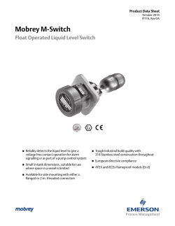
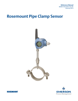
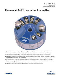

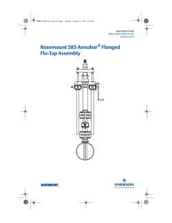

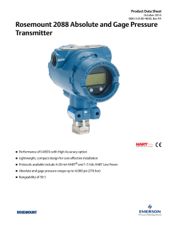

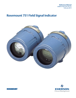
© Copyright 2026