
In vivo recording of aerodynamic force with an aerodynamic force
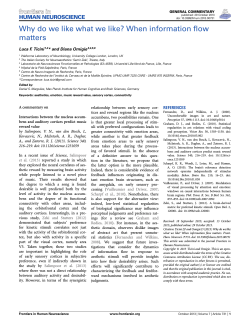
Downloaded from http://rsif.royalsocietypublishing.org/ on January 26, 2015
rsif.royalsocietypublishing.org
In vivo recording of aerodynamic force
with an aerodynamic force platform:
from drones to birds
David Lentink, Andreas F. Haselsteiner and Rivers Ingersoll
Report
Cite this article: Lentink D, Haselsteiner AF,
Ingersoll R. 2015 In vivo recording of aerodynamic force with an aerodynamic force
platform: from drones to birds. J. R. Soc.
Interface 12: 20141283.
http://dx.doi.org/10.1098/rsif.2014.1283
Received: 19 November 2014
Accepted: 17 December 2014
Subject Areas:
biomechanics, biomimetics
Keywords:
aerodynamic, force platform, in vivo,
non-intrusive, control volume, bird
Department of Mechanical Engineering, Stanford University, Stanford, CA 94305-3030, USA
Flapping wings enable flying animals and biomimetic robots to generate
elevated aerodynamic forces. Measurements that demonstrate this capability
are based on experiments with tethered robots and animals, and indirect
force calculations based on measured kinematics or airflow during free
flight. Remarkably, there exists no method to measure these forces directly
during free flight. Such in vivo recordings in freely behaving animals are
essential to better understand the precise aerodynamic function of their flapping wings, in particular during the downstroke versus upstroke. Here, we
demonstrate a new aerodynamic force platform (AFP) for non-intrusive aerodynamic force measurement in freely flying animals and robots. The platform
encloses the animal or object that generates fluid force with a physical control
surface, which mechanically integrates the net aerodynamic force that is transferred to the earth. Using a straightforward analytical solution of the Navier–
Stokes equation, we verified that the method is accurate. We subsequently
validated the method with a quadcopter that is suspended in the AFP and
generates unsteady thrust profiles. These independent measurements confirm
that the AFP is indeed accurate. We demonstrate the effectiveness of the AFP
by studying aerodynamic weight support of a freely flying bird in vivo. These
measurements confirm earlier findings based on kinematics and flow
measurements, which suggest that the avian downstroke, not the upstroke,
is primarily responsible for body weight support during take-off and landing.
1. Introduction
Author for correspondence:
David Lentink
e-mail: [email protected]
Electronic supplementary material is available
at http://dx.doi.org/10.1098/rsif.2014.1283 or
via http://rsif.royalsocietypublishing.org.
Animals that fly with flapping wings range from insects and bats to birds. The latter
have complex wing morphologies and motions, which affect their ability to generate
aerodynamic force in ways that are not fully understood [1]. The current method to
measure the aerodynamic force of a flapping wing directly is to tether an animal or
robot and measure the forces transferred through the tether with a load cell [2–4].
Tethered experiments with animals raise obvious concerns, but even tethered
robot experiments are inaccurate when confounding inertial forces cannot be
accounted for through dynamic modelling or measurement [5]. Whereas tethered
experiments have been the primary solution for evaluating aerodynamic force,
measurements during free flight manoeuvres are intrinsically more informative.
During free animal movement, aerodynamic force can be calculated non-intrusively
in three ways. First, the shape and motion of small animals, particularly insects, can
be measured to compute the flow fields and forces using computational fluid
dynamics [1,6]. Second, the body mass and acceleration distribution can be
measured and integrated using dynamics models to calculate force; this method
requires sacrificing animals after their body kinematics have been measured [7,8].
Finally, the airflow can be measured around the animal and integrated using (simplified versions of) the Navier–Stokes equations to calculate the net aerodynamic
force [9–17]. All these calculations are based on indirect measurements of
variables that need to be differentiated or integrated numerically to calculate
force, which introduces numerical error. A non-intrusive, real-time, direct force
measurement method (similar to the instrumented tether) does not exist for
& 2015 The Authors. Published by the Royal Society under the terms of the Creative Commons Attribution
License http://creativecommons.org/licenses/by/4.0/, which permits unrestricted use, provided the original
author and source are credited.
Downloaded from http://rsif.royalsocietypublishing.org/ on January 26, 2015
aerodynamic force platform
(b)
F1(t)
2
shear
beam
rsif.royalsocietypublishing.org
acrylic
(a)
T(t)
pressure
waves (t)
quadcopter
F2(t)
W
F3(t)
(c)
force ratio
(d )
s.d. and mean | mean
1.5
platform
F4(t)
F5(t)
force
sensor
s.d. and mean | mean
1.0
0.5
beam and quad
Fbeam = 62.4 ± 2.0 mN (n = 14)
0
8
16
Fbeam = 74.3 ± 1.3 mN (n = 14)
24
0
8
16
24
time (s)
time (s)
Figure 1. Aerodynamic force platform (AFP) working principle. (a) Validation of the platform: an overweight quadcopter, hung from a beam instrumented with load
cells, suspended in the AFP (an instrumented box). The inset shows a close-up of the quadcopter and its elongated battery—too heavy to take-off. (b) Based on
Newton’s third law, the thrust force of the quadcopter, T, is balanced by the beam’s support forces: F1 2 F2. The thrust force, T, is transferred to air, which transfers
it as a pressure force normal (and a small shear force tangential) to the walls of the AFP, resulting in the ground reaction force: F3 þ F4 þ F5. Pressure waves
transfer fluctuations in the thrust force at the speed of sound to the surrounding air, and ultimately the platform. The validation is carried out by generating
constant (c) and sinusoidal (d ) thrust profiles with the quadcopter, which are measured with the platform (green) versus beam (blue). Both thrust measurements
are normalized with the time-average thrust measured by the beam, which gives the force ratio. Both the standard deviation (left) and mean (right) traces overlap,
which demonstrates that the platform is accurate. (Online version in colour.)
studying free locomotion in fluids. For studying terrestrial locomotion such a solution does exist: the force platform
[18]. Here, we present an aerodynamic force platform (AFP)
that enables such measurements in fluids. We first justify the
new method with an analysis using the Navier–Stokes
equations, then validate it with a tethered quadcopter, and
finally we demonstrate in vivo recordings for a freely flying bird.
2. Fluid-mechanical analysis
AFPn ¼
The AFP is a box, instrumented with load cells, that encloses
the object or animal that generates the net unsteady fluid
force (figure 1a). It works based on Newton’s third law applied
to a fluid; the unsteady net fluid force needs to be supported
by an equal and opposite net force that acts on the control
volume boundary. The AFP is thus a mechanical representation of the control surface integral of the Navier–Stokes
equation [19] that calculates the net time-dependent force
ðð
ðð
¼ r @
xð
ÞdS r
ðtÞð
ÞdS
F(t)
uðtÞ n
u
uðtÞ n
@ t CS
CS
|fflfflfflfflfflfflfflfflfflfflfflfflfflfflfflfflfflffl
ffl{zfflfflfflfflfflfflfflfflfflfflfflfflfflfflfflfflfflfflffl} |fflfflfflfflfflfflfflfflfflfflfflfflfflfflfflfflfflffl
ffl{zfflfflfflfflfflfflfflfflfflfflfflfflfflfflfflfflfflfflffl}
convective
unsteady
ðð
ðð
dS ,
pðtÞ
ndS þ
tðtÞ n
CS
CS
|fflfflfflfflfflfflfflfflffl
ffl{zfflfflfflfflfflfflfflfflfflffl} |fflfflfflfflfflfflfflfflfflffl{zfflfflfflfflfflfflfflfflfflffl}
pressure
and t is the shear stress tensor. This net fluid force can be integrated exactly, provided that the three-dimensional velocity,
the pressure and shear stress are known over the complete
control surface as a function of time. In addition, small
phase differences owing to the finite propagation speed of
pressure waves (sound) must be small [20], which is the case
when the ‘AFP number’ of the control volume is much smaller
than one
(2:1)
shear
(t) is velocity, dS is the intewhere r is density, x is position, u
is the surface normal vector, p(t) is pressure
gration surface, n
Lf
1:
c
(2:2)
This condition is met when the control volume has an order
of magnitude smaller length scale, L, than the distance sound
travels, at speed c, within the shortest period of interest (1/f;
in which f is the frequency) that needs to be resolved in the
fluid force F(t).
Under this condition, the control surface integral (2.1) can be accurately evaluated. In this study, the
largest AFPn 0.022 (L 0.41 m, f 18 Hz, c ¼ 340 m s21),
which implies that the aerodynamic phase delay is of order
2% compared with the wingbeat time of the parrotlets
we study.
Whereas the unsteady and convective terms are significant in the bulk fluid, they vanish at the surface of the AFP.
The contour integral is simplified by substituting the
no-slip and no-flow condition on the surface of the physical
control surface
(x, t) ¼ 0:
u
(2:3)
J. R. Soc. Interface 12: 20141283
pressure (t)
difference
Downloaded from http://rsif.royalsocietypublishing.org/ on January 26, 2015
(a)
(b)
beam and quad
weight Gaga
0
0.6
0.4
weight Ray
platform
15
30
45
Gaga
0.5
0
0.1
0.2
time (s)
time (s)
0.3
5
5
0
0
5
2.0 5
5
1.5
5
1 Ray
1.0
0.5
0
0
5
0
5
1
5
5
3
2
3
4
wingbeat (–)
0
5
Figure 2. The aerodynamic force platform measures weight support of a quadcopter and freely flying birds in vivo. (a) The quadcopter’s unsteady thrust measured
with the platform (green) versus beam (blue) overlap, confirming that the platform is accurate (fourth-order Butterworth filter with 30 Hz cut-off for AFP and
beam). (b) Force-platform measurements of two Pacific parrotlets (Gaga and Ray) flying between two perches at 0.28 m distance in the AFP (fourth-order Butterworth filter with 60 Hz cut-off; green circle, take-off and landing; circle with black outline, video frame; grey area, downstroke). The snapshots illustrate that the
feathers open the wing surface like a venetian blind during the upstroke. (c) Calculation of wingbeat-averaged weight support based on raw data (flights, n ¼ 5;
birds, N ¼ 2). During take-off, Ray pushes off more vertically than Gaga, as illustrated in the electronic supplementary material videos. The start of the downstroke
and upstroke is defined as the moment when the wing is at its highest and lowest position, for the last wingstroke(s) we evaluate stroke direction. (Online version
in colour.)
This gives the following surface integral for the net fluiddynamic force, which depends on the pressure and shear
stress distribution that act on the surface of the AFP:
ðð
ðð
¼
dS :
F(t)
p(t)
ndS þ
t(t) n
(2:4)
CS
CS
|fflfflfflfflfflfflfflffl{zfflfflfflfflfflfflfflffl}
|fflfflfflfflfflfflfflfflfflffl{zfflfflfflfflfflfflfflfflfflffl}
pressure
shear
The pressure and shear stress at the surface are time-dependent and driven by the flow in the volume. In theory, it is
essential that the entire control surface is a rigid enclosure,
formed by walls, in order to guarantee that the net fluid
force is measured accurately (figure 1b). In practice, however,
viscous shear forces acting on the wall can typically be
ignored, compared with pressure forces if the Reynolds
number is much larger than unity [21]
ðð
F(t)
p(t)
ndS :
(2:5)
CS
|fflfflfflfflfflfflfflffl{zfflfflfflfflfflfflfflffl}
pressure
Finally, the net acceleration of the moving object or animal
can be calculated by dividing the net measured fluid force
minus body weight by the net associated mass
a(t) ¼
W
F(t)
:
M
(2:6)
3. Experimental validation
We developed an AFP, calibrated it, measured its natural frequency and validated it using independent load cell
measurements on a tethered quadcopter (figures 1 and 2a).
To obtain the net unsteady force with a mechanical implementation of the contour surface integral, the walls need to be
instrumented with load cells that measure the net fluid
forces (and moments). Similar to terrestrial force platforms
[18], the natural frequency of the instrumented walls of the
AFP needs to be an order of magnitude greater than the highest-frequency force fluctuation of interest (this requires high
stiffness and lightweight design). Further, the sensors need
sufficient sensitivity to detect the smallest forces and sufficient
dynamic range to resolve the largest forces.
Our first-generation AFP is essentially a lightweight and
stiff instrumented box with one open side for easy access
that is covered with an acrylic plate (figure 1a). The walls are
made out of thin (1 mm) balsa wood sheets that are combined
into a sandwich structure that maximize platform stiffness
with respect to weight (outer height width depth:
0.530 0.634 0.507 m; inner: 0.420 0.525 0.452 m). The
box is supported by three Nano 43 sensors (six-axis, with
SI-9-0.125 calibration, ATI Industrial Automation) that sample
force at 1 ms intervals with 2 mN resolution. To precisely
resolve vertical force, the AFP is connected statically determined (moment free) to the three load cells. The sensors are
arranged such that all are equally preloaded by AFP weight
(1.79 kg; linear calibration coefficient: 0.989; r 2 ¼ 1.000,
rounded to three decimals). The natural frequency was
measured by popping a balloon five times near the platform.
The natural frequency in the vertical (thrust) direction is
132 Hz, which is weakly coupled to a small-amplitude
105 Hz mode.
To validate and evaluate the accuracy of the AFP, we need
independent, ground-truth, aerodynamic force measurements. For this, we attached a quadcopter (Estes 4606
Proto X Nano, with a 1500 mAh Li –Po battery) to an instrumented aluminium beam with a Kevlar tether (two Nano 43
sensors; natural frequency beam þ quadcopter, 138 Hz;
linear calibration coefficient: 0.997; r 2 ¼ 1.000, rounded).
Visual comparison of the beam versus AFP measurement
suggests that the correspondence in force measurement
is remarkably close for a hand-controlled thrust profile
(figure 2a). For systematic validation, we modified the RC
J. R. Soc. Interface 12: 20141283
0.2
downstroke
upstroke
stroke
1.0
weight support (–)
force (N)
0.025
down
0.2
0.050
5
1.5
0.4
0.075
3
5
2.0
0.6
0.100
0
(c)
rsif.royalsocietypublishing.org
vertical aerodynamic force (N)
0.125
Downloaded from http://rsif.royalsocietypublishing.org/ on January 26, 2015
ave. force
ratio (2)
delay
(ms)
constant (n ¼ 14)
1.016 + 0.011
1.017 + 0.011
—
0.125 Hz
(84 periods)
1.014 + 0.006
1.014 + 0.006
2+2
0.250 Hz
(84 periods)
1.010 + 0.006
1.011 + 0.006
6+1
0.500 Hz
(84 periods)
1.017 + 0.004
1.018 + 0.005
8+1
control of the quadcopter to transmit semi-sinusoidal and constant thrust profiles using an Arduino Uno microcontroller
(figure 1c,d). All measured quadcopter thrust profiles (AFP
and beam) were filtered using a fourth-order Butterworth
filter with a cut-off frequency of 30 Hz (Matlab R2010a).
Comparison of the impulse and force ratio of the thrust
profiles measured with the AFP versus beam shows that
our AFP is accurate to within 2%—which is equivalent to
the load cell resolution limit of 2 mN (table 1). Using crosscorrelation, we find the time delay of the AFP is within its
natural vibration period. This time delay, owing to the transfer function of the AFP, is an order of magnitude larger than
the delay owing to the speed of sound (about 1 ms), showing
that the delay is primarily determined by the AFP’s structural
dynamics. The 2% higher force measured by the AFP is
equivalent to the missing shear force that should act on the
acrylic plate, which is not instrumented, assuming the Blasius
equation for boundary layer friction of a flat plate [22]. Our
back-of-the-envelope estimate of the net shear force, for a
measured near-wall flow speed of 0.95 ms21 (with a hotwire)
at 258C, gives a shear force equal to þ0.8% of the total force,
below the load cells’ resolutions, but in the right direction.
This supports our notion that we can probably ignore shear
at Reynolds numbers much greater than unity (Re 27 000
based on AFP height), which can greatly simplify future
AFP design. Comparative thrust measurements using an
acrylic front plate with and without a circular gap further
demonstrate that shear force can be ignored. These experiments show that the gap can be larger than 20% surface
area without affecting measurement accuracy. This enables
simple validation experiments and interaction with animals
flying in the AFP. Finally, we note that the AFP is a special
kind of infrasound microphone; for our AFP, we calculated
a sensitivity of up to 0.008 Pa. We found that high sensitivity
requires elimination of all infrasound noise sources in the laboratory; this includes switching off air conditioners because
they can increase noise by an order of magnitude. We also
found that if the AFP is installed statically determined, it
does not require special vibration isolation measures.
4. In vivo demonstration and outlook
To demonstrate that the AFP can directly measure the aerodynamic force generated by a freely flying animal, we
diameter
hole (m)
area
ratio (2)
total impulse
ratio (2)
ave. force
ratio (2)
0
0
1.019 + 0.004
1.019 + 0.004
0.100
0.175
0.036
0.109
1.020 + 0.011
1.018 + 0.003
1.020 + 0.011
1.018 + 0.003
0.250
0.223
1.021 + 0.003
1.021 + 0.003
trained two Pacific parrotlets (Forpus coelestis; 28 g; 0.2 m
wingspan; wingbeat frequency 20 Hz) to fly between two
perches in the AFP. The perches were connected to the
acrylic front panel. To enable training and cueing and
rewarding of the bird, we made a gap in the acrylic front
panel of 0.071 m2, which has no measurable effect on accuracy (table 2). Each parrotlet was trained using habituation
and positive reinforcement [23 –25], based on millet seed
rewards to fly to a target stick and touch it with its beak
(food and water ad libitum; cages have enrichment, animals
were not sacrificed, all training and experimental procedures were approved by Stanford’s Administrative Panel on
Laboratory Animal Care). Its aerodynamic weight support
was measured in vivo within a wingbeat using the AFP,
whereas the start and end of the wingbeat were determined
with a synchronized high-speed camera at 1000 fps (Phantom
Miro M310; figure 2b). We selected a 60 Hz low-pass cut-off
frequency to avoid interference with the wing beat frequency.
The recordings demonstrate that the upstroke of generalist
birds, such as the parrotlet, does not aerodynamically support body weight (much) during take-off and landing
manoeuvres (figure 2c; irrespective of interspecific differences in flight style). Instead they generate a vertical force
of up to twice their body weight during the downstroke.
This direct force measurement validates earlier indirect
force estimates based on kinematic [7,8], flow [12,13,26,27]
and in vivo pressure measurements [28,29], which indicate
that the avian upstroke produces little weight support
during slow flight [30].
The capability of the AFP to measure aerodynamic
force in vivo is applicable across taxa and addresses the welfare of experimental animals; it is non-invasive, no-touch
and thus relatively low-stress. Future AFPs can be improved
by constructing them using sandwich structures consisting
of carbon fibre and Nomex honeycomb. Optical access
can be improved using tensioned transparent membranes.
The measurement sensitivity can be increased with custom
load cells that harness extremely precise capacitive or
interferometric displacement sensors. Ultimately, the threedimensional force vector can be resolved with a fully enclosing AFP. This approach can be extended to much larger
volumes by composing the side walls out of individually
instrumented plates to obtain higher natural frequencies,
which also allows for decomposition of force components.
The mechanical design of the platform can be scaled down
for insects to achieve higher sensitivities and natural frequencies. Scaling up or down involves straightforward
lightweight structural design [31] for appropriate natural frequencies [31,32] of the AFP and the load cells, similar to the
design of a terrestrial force plate [18]. The main difference
4
J. R. Soc. Interface 12: 20141283
experiment
total impulse
ratio (2)
Table 2. A hole in one of the sidewalls of the AFP has no effect on
vertical impulse and force accuracy (average of five recordings of 6 s each).
rsif.royalsocietypublishing.org
Table 1. Validation of AFP versus beam measurement of integrated
impulse and instantaneous force of a quadcopter shows that the AFP is
accurate and time-resolved.
Downloaded from http://rsif.royalsocietypublishing.org/ on January 26, 2015
natural habitat. Here, we have already demonstrated that
AFPs can be used to evaluate the aerodynamic force
generation of drones non-intrusively, and freely flying birds
in vivo, with remarkable precision.
Acknowledgements. We thank A.K. Stowers for help with electronics and
calibration, and E. Ravnan and A.A. Biewener for support.
Funding statement. This research is supported by ONR MURI grant no.
N00014-10-1-0951 and the KACST Center of Excellence for Aeronautics and Astronautics at Stanford. The AFP was developed by D.L.
1.
Shyy W et al. 2013 An introduction to flapping wing
aerodynamics. Cambridge, UK: Cambridge University
Press.
2. Dickinson MH, Lehmann FO, Sane SP. 1999 Wing
rotation and the aerodynamic basis of insect flight.
Science 284, 1954–1960. (doi:10.1126/science.284.
5422.1954)
3. Taylor GK, Thomas AL. 2003 Dynamic flight stability
in the desert locust Schistocerca gregaria. J. Exp.
Biol. 206, 2803–2829. (doi:10.1242/jeb.00501)
4. Dickson WB, Straw AD, Dickinson MH. 2008
Integrative model of Drosophila flight. AIAA J. 46,
2150–2164. (doi:10.2514/1.29862)
5. Zhao L, Huang Q, Deng X, Sane SP. 2010 Aerodynamic
effects of flexibility in flapping wings. J. R. Soc. Interface
7, 485–497. (doi:10.1098/rsif.2009.0200)
6. Liu H. 2002 Computational biological fluid
dynamics: digitizing and visualizing animal
swimming and flying. Integr. Comp. Biol. 42,
1050–1059. (doi:10.1093/icb/42.5.1050)
7. Ros IG, Bassman LC, Badger MA, Pierson AN,
Biewener AA. 2011 Pigeons steer like helicopters
and generate down- and upstroke lift during
low speed turns. Proc. Natl Acad. Sci. USA 108,
19 990–19 995. (doi:10.1073/pnas.1107519108)
8. Hedrick TL, Usherwood JR, Biewener AA. 2004 Wing
inertia and whole-body acceleration: an analysis of
instantaneous aerodynamic force production in
cockatiels (Nymphicus hollandicus) flying across a
range of speeds. J. Exp. Biol. 207, 1689 –1702.
(doi:10.1242/jeb.00933)
9. Muijres FT, Henningsson P, Stuiver M, Hedenstro¨m A.
2012 Aerodynamic flight performance in flap-gliding
birds and bats. J. Theor. Biol. 306, 120–128. (doi:10.
1016/j.jtbi.2012.04.014)
10. Spedding G, Rose´n M, Hedenstro¨m A. 2003 A family
of vortex wakes generated by a thrush nightingale
in free flight in a wind tunnel over its entire natural
range of flight speeds. J. Exp. Biol. 206,
2313–2344. (doi:10.1242/jeb.00423)
11. Rose´n M, Spedding GR, Hedenstro¨m A. 2004 The
relationship between wingbeat kinematics and
vortex wake of a thrush nightingale. J. Exp. Biol.
207, 4255–4268. (doi:10.1242/jeb.01283)
12. Muijres FT, Johansson LC, Hedenstrom A. 2012
Leading edge vortex in a slow-flying passerine. Biol.
Lett. 8, 554– 557. (doi:10.1098/rsbl.2012.0130)
13. Muijres FT, Johansson LC, Hedenstrom A. 2012
Vortex wake, downwash distribution, aerodynamic
performance and wingbeat kinematics in slowflying pied flycatchers. J. R. Soc. Interface 9,
292 –303. (doi:10.1098/rsif.2011.0238)
14. Warrick DR, Tobalske BW, Powers DR. 2005
Aerodynamics of the hovering hummingbird. Nature
435, 1094–1097. (doi:10.1038/nature03647)
15. Warrick DR, Tobalske BW, Powers DR. 2009 Lift
production in the hovering hummingbird.
Proc. R. Soc. B 276, 3747 –3752. (doi:10.1098/rspb.
2009.1003)
16. Provini P, Tobalske BW, Crandell KE, Abourachid A.
2012 Transition from leg to wing forces during takeoff in birds. J. Exp. Biol. 215, 4115 –4124. (doi:10.
1242/jeb.074484)
17. Muijres FT, Spedding GR, Winter Y, Hedenstro¨m A.
2011 Actuator disk model and span efficiency of
flapping flight in bats based on time-resolved PIV
measurements. Exp. Fluids 51, 511–525. (doi:10.
1007/s00348-011-1067-5)
18. Biewener AA, Full RJ. 1992 Force platform and kinematic
analysis. In Biomechanics: structures and systems.
A practical approach (ed. A Biewener), pp. 45–73.
New York, NY: IRL at Oxford University Press.
19. Mohebbian A, Rival DE. 2012 Assessment of the
derivative-moment transformation method for
unsteady-load estimation. Exp. Fluids 53, 319–330.
(doi:10.1007/s00348-012-1290-8)
20. Mueller TJ. 2002 Aeroacoustic measurements. Berlin,
Germany: Springer.
21. Guyon E. 2001 Physical hydrodynamics. Oxford, UK:
Oxford University Press.
22. Anderson JD. 2001 Fundamentals of aerodynamics,
vol. 2. New York, NY: McGraw-Hill.
23. Skinner BF. 1938 The behavior of organisms: an
experimental analysis. New York, NY: AppletonCentury-Crofts.
24. Abramson CI. 1994 A primer of invertebrate learning:
the behavioral perspective. Washington, DC:
American Psychological Association.
25. McGreevy P, Boakes R. 2011 Carrots and sticks:
principles of animal training. Sydney, Australia:
Darlington Press.
26. Kirchhefer AJ, Kopp GA, Gurka R. 2013 The near
wake of a freely flying European starling. Phys.
Fluids 25, 051902. (doi:10.1063/1.4807064)
27. Su J-Y, Ting S-C, Chang Y-H, Yang J-T. 2012
A passerine spreads its tail to facilitate a rapid recovery
of its body posture during hovering. J. R. Soc. Interface
9, 1674–1684. (doi:10.1098/rsif.2011.0737)
28. Usherwood JR, Hedrick TL, Biewener A. 2003 The
aerodynamics of avian take-off from direct pressure
measurements in Canada geese (Branta canadensis).
J. Exp. Biol. 206, 4051–4056. (doi:10.1242/jeb.00624)
29. Usherwood JR, Hedrick TL, McGown CP, Biewener A.
2005 Dynamic pressure maps for wings and tails of
pigeons in slow, flapping flight, and their energetic
implications. J. Exp. Biol. 208, 355–369. (doi:10.
1242/jeb.01359)
30. Tobalske BW. 2007 Biomechanics of bird flight. J. Exp.
Biol. 210, 3135–3146. (doi:10.1242/jeb.000273)
31. Megson THG. 2012 Aircraft structures for engineering
students. Amsterdam, The Netherlands: Elsevier.
32. Thomson W. 1996 Theory of vibration with
applications. New York, NY: CRC Press.
33. Wolken-Mo¨hlmann G, Knebel P, Barth S, Peinke J.
2007 Dynamic lift measurements on a FX79W151A
airfoil via pressure distribution on the wind tunnel
walls. J. Phys. Conf. Ser. 75, 012026. (doi:10.1088/
1742-6596/75/1/012026)
34. Abramson CI. 1990 Habituation. Washington, DC:
American Psychological Association.
J. R. Soc. Interface 12: 20141283
References
5
rsif.royalsocietypublishing.org
between an AFP and terrestrial force plate is that AFPs are
much more sensitive to pressure per unit surface area. This
sensitivity also makes the AFP applicable to wind tunnels
in which they could integrate the wall pressure distribution
to determine the vertical aerodynamic force [33]. Theoretically, this real-time method should work for many
animals, robots and objects that generate a net force in a
fluid. Both vertebrates and invertebrates can be trained to
behave in the AFP using habituation and operant conditioning [23–25,34]; alternatively, an attractive food source can be
placed in the AFP to work with untrained animals in their


© Copyright 2026