
TelevisNet Data recording and alarm management software
TelevisNet Data recording and alarm management software, with graphic display of system User Manual GB Invensys Controls Europe An Invensys Company CONTENTS 1 2 3 Using the manual.................................................................................................................................................... 5 Minimum system requirements.......................................................................................................................... 6 2.1 2.2 Foreword ............................................................................................................................................................................................ 6 Personal computer requirements ................................................................................................................................................ 6 3.1 3.2 3.3 Introduction to TelevisNet............................................................................................................................................................. 7 Main features .................................................................................................................................................................................... 7 TelevisNet Components ................................................................................................................................................................. 7 3.4 Compatible instruments ................................................................................................................................................................. 8 4.1 4.2 4.3 4.4 4.5 Important notes: read before installation ................................................................................................................................. 9 Important notes on database........................................................................................................................................................ 9 Installation.......................................................................................................................................................................................... 9 TSUser ................................................................................................................................................................................................. 9 Updating ............................................................................................................................................................................................. 9 4.6 Incompatibility notes during installation/update .................................................................................................................. 10 4.7 Removing software and data ...................................................................................................................................................... 10 Introduction ............................................................................................................................................................. 7 3.3.1 Software component ........................................................................................................................................................................................................................ 7 3.3.2 PCInterface component ................................................................................................................................................................................................................... 7 3.3.3 BlueCard component........................................................................................................................................................................................................................ 7 3.3.4 Network connection accessory components ............................................................................................................................................................................. 7 3.3.5 LanAdapter........................................................................................................................................................................................................................................... 7 3.3.5.1 WiFi LanAdapter...................................................................................................................................................................................................................... 7 3.3.5.2 BusAdapter ............................................................................................................................................................................................................................... 7 3.3.5.3 RadioAdapter ........................................................................................................................................................................................................................... 7 3.3.5.4 SmartAdapter........................................................................................................................................................................................................................... 7 4 Software installation .............................................................................................................................................. 9 4.5.1 Rules for safe updating .................................................................................................................................................................................................................... 9 4.5.1.1 Before updating....................................................................................................................................................................................................................... 9 4.5.1.2 Whilst updating ....................................................................................................................................................................................................................... 9 4.5.1.3 After updating ......................................................................................................................................................................................................................... 9 4.5.2 Updating the database ................................................................................................................................................................................................................... 10 4.5.3 Moving TelevisNet to another computer.................................................................................................................................................................................. 10 4.6.1 4.6.2 4.6.3 4.6.4 4.7.1 4.7.2 5 Notes on installation from CD ..................................................................................................................................................................................................... 10 Notes on installation on Windows XP Home ........................................................................................................................................................................... 10 Editing the file DtmCfg.ini during update................................................................................................................................................................................. 10 Incompatibility with AS400 client................................................................................................................................................................................................ 10 Removing the TelevisNet program ............................................................................................................................................................................................. 10 Removing third party programs................................................................................................................................................................................................... 10 Hardware installation .......................................................................................................................................... 12 5.1 5.2 5.3 5.4 5.5 TelevisNet to instrument networks ........................................................................................................................................... 12 BlueCard Installation ..................................................................................................................................................................... 12 Using LanAdpter and LanAdapter WiFi devices ..................................................................................................................... 12 Installing and addressing instruments in network................................................................................................................. 12 Network Topologies ...................................................................................................................................................................... 12 5.5.1 Main network on serial, USB port ............................................................................................................................................................................................... 13 5.5.2 Additional networks on serial, USB, Ethernet, WiFi ports .................................................................................................................................................... 13 5.5.2.1 PCInterface RS-232 + LanAdapter network................................................................................................................................................................... 13 5.5.2.2 PCInterface RS-232 + LanAdapter WiFi network ......................................................................................................................................................... 13 5.5.2.3 PCInterface RS-232 + LanAdapter + LanAdapter WiFi network.............................................................................................................................. 14 5.5.2.4 PCInterface RS-232 + RadioAdapter network............................................................................................................................................................... 15 5.5.3 Fieldbus wiring recommendations .............................................................................................................................................................................................. 15 6 First Startup and Services Status...................................................................................................................... 16 6.1 6.2 Foreword .......................................................................................................................................................................................... 16 First Startup ..................................................................................................................................................................................... 16 6.3 Web Application Work Area ....................................................................................................................................................... 16 6.2.1 6.2.2 6.3.1 Web login page................................................................................................................................................................................................................................. 16 Welcome page .................................................................................................................................................................................................................................. 16 Page structure ................................................................................................................................................................................................................................... 16 TelevisNet 2/46 6.3.2 6.3.3 6.3.4 6.4 6.5 6.5.1 7 Navigation menu .............................................................................................................................................................................................................................. 16 Status bar ........................................................................................................................................................................................................................................... 16 Status icons........................................................................................................................................................................................................................................ 17 Action/command icons ................................................................................................................................................................ 18 Web application for handheld devices..................................................................................................................................... 18 Web login page on handheld device.......................................................................................................................................................................................... 18 PC configuration for TelevisNet ....................................................................................................................... 19 7.1 7.2 Web application installation........................................................................................................................................................ 19 Access to systems........................................................................................................................................................................... 19 7.2.1.1 7.2.1.2 7.2.1.3 7.2.1.4 7.2.1.5 Local display ........................................................................................................................................................................................................................... 19 LAN / WAN (VPN) network................................................................................................................................................................................................ 19 Public static IP........................................................................................................................................................................................................................ 19 Point-to-point connection via modem ........................................................................................................................................................................... 19 Connection via router.......................................................................................................................................................................................................... 19 7.3 7.4 Cassini Web Server ........................................................................................................................................................................ 19 Known Web configuration problems and solutions ............................................................................................................. 19 7.5 Creating a modem connection to a public network............................................................................................................. 20 7.6 Remote access settings................................................................................................................................................................. 21 7.4.1 7.4.2 Presence of "_" in computer name............................................................................................................................................................................................ 19 Navigating with the 'Back' button on the display .................................................................................................................................................................. 20 7.5.1 Modems supported ......................................................................................................................................................................................................................... 20 7.5.2 SMTP protocol .................................................................................................................................................................................................................................. 20 7.5.3 Installation of fax service ............................................................................................................................................................................................................... 20 7.5.4 Installation of GSM modem .......................................................................................................................................................................................................... 20 7.5.4.1 Modems supported.............................................................................................................................................................................................................. 20 7.5.4.2 Support for SMS with header............................................................................................................................................................................................ 20 8 9 7.6.1 7.6.2 Access via modem connection..................................................................................................................................................................................................... 21 Access via LAN/WANconnection ................................................................................................................................................................................................. 21 Televis Management............................................................................................................................................ 22 8.1 8.2 8.3 8.4 8.5 8.6 8.7 8.8 Login .................................................................................................................................................................................................. 22 Televis Management window...................................................................................................................................................... 22 Televis server application tab ..................................................................................................................................................... 22 General Tab ..................................................................................................................................................................................... 22 Communication Networks Tab................................................................................................................................................... 23 Fieldbus Tab .................................................................................................................................................................................... 24 Database Tab................................................................................................................................................................................... 24 Software License Tab .................................................................................................................................................................... 24 9.1 9.2 Automatic detection of controllers network.......................................................................................................................... 25 Settings Tab ..................................................................................................................................................................................... 25 9.3 Computer Tab ................................................................................................................................................................................. 31 TelevisNet Configuration via Web ................................................................................................................... 25 9.2.1 Networks Tab .................................................................................................................................................................................................................................... 25 9.2.1.1 View Tab.................................................................................................................................................................................................................................. 25 9.2.1.2 Networks detection tab ...................................................................................................................................................................................................... 25 9.2.1.3 Maintenance Tab .................................................................................................................................................................................................................. 27 9.2.1.4 Fieldbus Tab ........................................................................................................................................................................................................................... 27 9.2.1.5 User Names Tab .................................................................................................................................................................................................................... 27 9.2.2 Alarm Categories Tab ..................................................................................................................................................................................................................... 27 9.2.2.6 Creating alarm categories................................................................................................................................................................................................... 28 9.2.2.7 Examples of possible configurations ............................................................................................................................................................................... 28 9.2.2.8 Notes on Alarm Categories................................................................................................................................................................................................ 28 9.2.3 Recipients Tab................................................................................................................................................................................................................................... 28 9.2.4 Scheduler Tab ................................................................................................................................................................................................................................... 28 9.2.4.9 Creating a Scheduled operation ....................................................................................................................................................................................... 29 9.2.4.10 Print Scheduling .................................................................................................................................................................................................................... 29 9.2.4.11 Data Export Scheduling....................................................................................................................................................................................................... 29 9.2.4.12 Scheduling commands to instruments ........................................................................................................................................................................... 29 9.2.5 Accounts Tab..................................................................................................................................................................................................................................... 29 9.2.6 Layout Designer Tab........................................................................................................................................................................................................................ 29 9.3.1 9.3.2 9.3.3 System Information ......................................................................................................................................................................................................................... 31 Printers Tab........................................................................................................................................................................................................................................ 31 Fax Tab................................................................................................................................................................................................................................................ 31 TelevisNet 3/46 10 9.3.3.1 Notes on fax management................................................................................................................................................................................................. 31 9.3.4 SMS Tab .............................................................................................................................................................................................................................................. 32 9.3.5 E-mail Tab .......................................................................................................................................................................................................................................... 32 9.3.5.2 Connections for sending E-mails ...................................................................................................................................................................................... 32 9.3.6 Interfaces Tab.................................................................................................................................................................................................................................... 33 TelevisNet functions via web......................................................................................................................... 34 10.1 Functions Tab.................................................................................................................................................................................. 34 10.1.1 10.1.2 10.1.3 10.1.3.1 10.1.4 10.1.4.2 10.1.4.3 10.1.5 10.1.5.4 11 11.1 Data display in TelevisNet .............................................................................................................................. 37 Data Tab ........................................................................................................................................................................................... 37 11.1.1 11.1.2 11.1.3 11.1.4 11.1.5 11.1.5.1 11.1.6 11.1.7 11.1.8 11.2 Start/Stop Tab ............................................................................................................................................................................................................................. 34 Commands Tab ........................................................................................................................................................................................................................... 34 Parameters Tab ........................................................................................................................................................................................................................... 35 Parameter Tab for 8000/9000 Series (13/18 DIN) EWCM Models.......................................................................................................................... 35 RVD Tab ........................................................................................................................................................................................................................................ 36 Operational limits ................................................................................................................................................................................................................. 36 Basicom FanCoil RVD........................................................................................................................................................................................................... 36 Layout Tab .................................................................................................................................................................................................................................... 36 Layout Limits .......................................................................................................................................................................................................................... 36 Overview Tab ............................................................................................................................................................................................................................... 37 Real-time Tab .............................................................................................................................................................................................................................. 37 Real time table on handheld device ..................................................................................................................................................................................... 37 Real time chart tab .................................................................................................................................................................................................................... 38 Historical Table Tab ................................................................................................................................................................................................................... 38 Creating a Historical table .................................................................................................................................................................................................. 38 Historical Chart Tab ................................................................................................................................................................................................................... 38 User Activities Logging Tab ..................................................................................................................................................................................................... 39 Archive Tab .................................................................................................................................................................................................................................. 39 Alarms Tab ....................................................................................................................................................................................... 39 11.2.1 Real time alarms Tab................................................................................................................................................................................................................. 39 11.2.1.1 Alarms on handheld devices.............................................................................................................................................................................................. 39 11.2.2 Historical alarms Tab ................................................................................................................................................................................................................. 40 11.2.2.2 Notification message structure ......................................................................................................................................................................................... 40 12 System Maintenance ........................................................................................................................................ 41 12.1 12.2 12.3 Information on system.................................................................................................................................................................. 41 Automatic operating efficiency check...................................................................................................................................... 41 Security ............................................................................................................................................................................................. 41 12.4 12.5 12.6 Database backup ............................................................................................................................................................................ 42 Instrument profiles maintenance............................................................................................................................................... 42 Internet Explorer ............................................................................................................................................................................ 42 12.3.1 12.3.2 12.3.3 12.3.4 12.3.5 12.3.6 12.3.7 13 14 15 12.6.1 12.6.2 Changing the WindowsTSUser password............................................................................................................................................................................. 41 Changing the TelevisNET Administrator user password.................................................................................................................................................. 41 Blocking remote control .......................................................................................................................................................................................................... 41 Database........................................................................................................................................................................................................................................ 41 Updating the operating system .............................................................................................................................................................................................. 41 Antivirus ........................................................................................................................................................................................................................................ 41 Firewall .......................................................................................................................................................................................................................................... 41 Setting a default language ....................................................................................................................................................................................................... 42 Deleting cookies, temporary files and caches.................................................................................................................................................................... 42 Glossary ............................................................................................................................................................... 43 Limitation of responsibility ............................................................................................................................ 44 Analytical Index ................................................................................................................................................. 45 TelevisNet 4/46 1 USING THE MANUAL To allow quick, easy reference, the manual has been designed with the following features: References References column: The reference symbols on the left of text indicate the different topics; this helps you find the information you need quickly. Cross references Cross references: All words in italics are listed in the analytical index with the number of the page where they are dealt with in more detail; in the following text passage, for example: "If there are 2 compressors in the system the minimum time between the switching on of the two compressors" is observed The words written in italics can be found in the analytical index under "minimum time" and "compressors" where the page numbers are given referring you to the compressors section and the minimum switch on times for compressors. In the "on-line" (computer) manual, the words in italics are "hyperlinks" (i.e. mouse-clickable links), connecting up the different parts of the manual and making it "navigable". Highlighting icons: Some text passages are marked by icons in the references column, which have the following meanings: Important! : information that the user must be aware of, otherwise there could be negative consequences for the system or hazards for people, devices, data, etc..; the user must read this information. Note / highlight: further information on the topic in question that the user should be aware of Tip: a suggestion that could help the user to understand and make better use of the information provided GB Invensys Controls Europe An Invensys Company 2 2.1 MINIMUM SYSTEM REQUIREMENTS Foreword This guide contains all the general information needed for the installation and initial start-up of TelevisNet. For all other settings and options, see the full technical documentation on the CD-ROM. You are urged to follow the instructions carefully to ensure that the installation and initial launch of the software are done correctly. 2.2 Personal computer requirements Televis Net: Hardware: o Microprocessor: x86 1 GHz or better. o RAM: 1 GB. o Fixed disk: 10 Gb of free space. o Minimum monitor resolution: 1024x768 (recommended 1280x1024). o Sufficient number of serial and/or USB ports (for PCinterface, modem, etc.). See section on PC to instrument networks. o Mouse or other pointing devices. Operating System: o Windows XP Home SP2 or SP3. o Windows XP Professional SP2 or SP3. Browsers supported o Internet Explorer 6. o Mozilla Firefox 2. Operating system languages: o Windows XP Česky o Windows XP Deutsch o Windows XP English o Windows XP Español o Windows XP Français o Windows XP Italiano o Windows XP Português o Windows XP Русский o Windows XP 简体中文 Compatibledatabases: o Microsoft SQL Server 2000. o Microsoft SQL 2000 Server Desktop Engine (MSDE). Software/Networking/Firewall settings: o E-mail: TCP port 25 for SMTP protocol must be available. o Web: TCP port 80 for HTTP protocol must be available. TelevisNet 6/46 3 INTRODUCTION 3.1 Introduction to TelevisNet TelevisNet is a system monitoring and management program with a multi-lingual interface designed for Windows platforms. 3.2 Main features The suite is made up of the following applications: Televis Application Server Televis Management Televis Monitor Web access interface Televis LifeTest Migration Tool 3.3 TelevisNet Components The basic components and accessories are illustrated below. 3.3.1 Software component The software application has a graphic interface and its functions will be illustrated in this manual. TelevisNet is available in the following languages: Česky Deutsch English Español Français Italiano Português Русский 简体中文 PCInterface End User License BlueCard 3.3.2 PCInterface component The RS-232/EIA-485 protocol conversion module, known as the PCInterface, is necessary for data communication between TelevisNet and the network of compatible instruments and is available in the following versions. PC Interface 1110: has a single RS-485 serial port. PC Interface 1120: has two RS-485 serial ports, making it possible to branch the network in two directions. The computer on which TelevisNet is installed and the PCInterface should be powered in parallel from a single electrical socket. 3.3.3 BlueCard component To use the TelevisNet program, you must have an original End User License. The license consists of a memory module known as the BlueCard, which must be inserted in the allocated slot in the PCInterface connection device. For installation instructions, see the chapter BlueCard installation. Important: each PCInterface connected to the personal computer with the TelevisNet software software must be activated with an original BlueCard in the slot. Each installation requires one (and only one) BlueCard containing the original end user licence for the software; all remaining PCInterfaces connected to the same personal computer must be activated by expansion BlueCards. 3.3.4 Network connection accessory components 3.3.5 LanAdapter The LanAdapter is an Ethernet /RS-485 interface module that allows communication via LAN between a monitoring system and an instrument network. The LanAdapter supports controller networks with either Micronet/Televis or MODBUS protocol. 3.3.5.1 WiFi LanAdapter Same as LanAdpater but with WiFi / RS-485 interface. 3.3.5.2 BusAdapter Device with TTL/RS-485 communication interface for connecting Eliwell controllers to wired supervision and monitoring networks. 3.3.5.3 RadioAdapter Same as BusAdpater but with wireless interface for connecting TTl/RS-485 networks. 3.3.5.4 SmartAdapter The SmartAdapter is a ModBUS protocol converter for Televis networks. It allows the TelevisNet software to be connected to ModBUS protocol instruments via an RS-485 interface. TelevisNet 7/46 3.4 Compatible instruments The Compatible instruments document lists all the instruments supported by a certain version of TelevisNet. Periodically, with releases of new instruments or variants of existing ones, program upgrades are made available to support them. The compatibility table lists the following information for each instrument: Description of model. Family ID, i.e. type of firmware installed on device. Model ID. Polycarbonate ID. Firmware version. Parameters table: states whether the Parameters Table software function is available. Product code: gives the end product codes of the compatible instruments. TelevisNet 8/46 4 SOFTWARE INSTALLATION 4.1 Important notes: read before installation Any user carrying out the installation, update or removal of TelevisNet must have Windows administrator rights. You are advised to close all applications before proceeding with the installation, update or removal of the program. Note that the installation program may request the rebooting of the system during the procedure. This request must be complied with. Make sure that the computer where the product is to be installed complies with the minimum requirements described in the chapter Minimum system requirements. To guarantee maximum data security, you are advised to install TelevisNet on a dedicated system monitoring computer. The efficient operation of the product cannot be guaranteed if programs other than those stated in this manual are used on the same computer, even if not continuously. 4.2 Important notes on database If SQL Server 2000 or SQL Server 2000 MSDE are not present, then SQL Server 2000 MSDE SP3a will be installed. If either SQL Server 2000 or SQL Server 2000 MSDE are present, then the installation will continue with the existing program. In this case the user must make sure that the user sa password (MSDE administrator) is left blank, otherwise the installation wizard will not be able to configure the databases correctly. The installation wizard will then change the sa password. If the already installed version of SQL Server or MSDE is earlier than 2000, the installation will be blocked. 4.3 Installation Insert the provided installation CD-ROM into the CD drive on your personal computer and wait until the installation wizard starts the guided installation procedure. The first window gives the welcome message and then the installation starts automatically. From now on, follow the prompts in the wizard windows to complete the installation. After this first installation, you will be asked to restart your PC to update with the new settings. Restart your PC. 4.4 TSUser During the installation the TSUser will be created as Administrator to allow TelevisNet to perform some automatic procedures Remote connections with modem connection. Sending E-mails. etc. To prevent remote connection with unwanted users, during the installation you are advised to change the Windows TSUser default password. The default password is TS. See the chapter Change Windows TS User password. 4.5 Updating It is possible to update to a more recent version of TelevisNet, without changing any of the same settings and keeping all the logged data. 4.5.1 Rules for safe updating 4.5.1.1 Before updating 1. 2. 3. 4. 5. 6. 4.5.1.2 1. 2. 4.5.1.3 1. Create a historical data chart of the last 6 months; if the system hasn't logged any data for a long time, you are advised to delete all the historical data with the Televis Application Server program. Check the size of the database: if greater than 1GB, you are advised to make a backup of the database and then delete all the historical data with either the Televis Management (versions 4.0.0 or later) or Administrative Tool (versions 3.1.0 or later) programs and contact Eliwell Technical Support to run the database maintenance programs. Shut down all applications. With TelevisNet 3.1.0 or earlier, shut down the Televis NET, Televis Life Test and Televis Application Server applications. With TelevisNet 4.0.0 or later, stop the Televis Application Server and Televis Life Test services. Stop the Cassini Web Server service. Whilst updating Maintain the default settings. Do not interrupt the procedure for any reason. After updating With the first startup after updating, verify the identity of the instruments present in the system to make sure that none of the drivers have been changed. If instruments classified as "new" are detected, you are strongly advised to save the new network configuration. TelevisNet could behave erratically if the configuration saved is not perfectly matched to the instruments in the system and their drivers. NOTE: "false" nolinks may have been caused by the first versions of TelevisNet; this problem will be resolved when the new network configuration is saved. TelevisNet 9/46 2. Start the data acquisition. You are advised to wait at least one complete acquisition cycle (14 minutes) to make sure the program is logging the data correctly. As a further check, view the historical data chart again. Important: Do not leave the site until you are totally sure that the update has been completed successfully and that TelevisNet is logging the data and managing the alarms. 4.5.2 Updating the database The database update is carried out automatically with the update of TelevisNet with the installation CD. You are advised however to check that the scripts are written correctly: check the files in the directories "C:\Programmi\Eliwell\Televis System\Database\DBUpgrade\NET-LINK\TO_XX.YY.ZZ\to_XX.YY.ZZ.sql.OUT". Files containing the "msg" string show that an error has occurred. For example, if an update from rel. 1.4.2 to rel.3.0.0 is done, the following scripts will be written in sequence and the related output files will be generated: "To_02.00.00.sql" updates the software from 1.4.2 to 2.0.0 and generates "To_02.00.00.sql.OUT" "To_02.01.00.sql" updates the software from 2.0.0 to 2.1.0 and generates "To_02.01.00.sql.OUT" "To_03.00.00.sql" updates the software from 2.1.0 to 3.0.0 and generates "To_03.00.00.sql.OUT" 4.5.3 Moving TelevisNet to another computer The procedure described below explains how to move the TelevisNet software and its archives from an Origin computer to a Destination computer, updating the version at the same time: 1. Origin: follow the instructions in the chapter "Rules for safe updating", especially the section "Before updating". 2. Origin: use Televis Management to make a security backup of the database and save it on a safe support. 3. Origin: update to the chosen version of TelevisNet. 4. Origin: check that TelevisNet operates properly. 5. Destination: carry out theinstallation of the chosen version of TelevisNet. 6. Destination: check that the TelevisNet works properly with the database created by the installation program. 7. BothOrigin and Destination: follow the instructions in the chapter "Rules for safe updating", especially the section "Before updating". Also, stop the SQL Server and SQL Server Agent services. 8. Copy the following files fromOrigin to Destination, overwriting the existing files and conserving the structure: a. Database b. Layout c. LayoutImages d. Templates 9. Destination: start the SQL Server and SQL Server Agent services. 10. Destination: start Televis Application Server and Televis Life Test. 11. Destination: check that TelevisNet works properly, especially the data logging and alarms management. 4.6 Incompatibility notes during installation/update 4.6.1 Notes on installation from CD Whilst installing/updating a TelevisNet system from CD, the following kind of message may appear: "Please insert Disk : n°. To remedy this problem, simply copy the contents of the installation CD on to the local hard disk and do the update, running the "setup.exe" program from the hard disk. 4.6.2 Notes on installation on Windows XP Home An installation on Windows XP Home may generate the following error message: "Windows Installer cannot update the system file C:\WINNT\system32\mfc42.dll…" Simply click "OK" and carry on. The installation will be completed correctly. 4.6.3 Editing the file DtmCfg.ini during update If doing an update from previous versions of TelevisNet, you are advised to open the file "C:\windows\system32\DtmCfg.ini" and delete all lines beginning with "#". This step is not necessary if this is the first installation of TelevisNet on your computer. 4.6.4 Incompatibility with AS400 client Problems have occurred on computers on which AS400 client had been installed. The AS400 client installation program changes some of the standard Windows settings without re-correcting them after the operation. To remedy this problem simply proceed with the installation of the component of Windows MDAC 2.8 which, for convenience, has been included in the TelevisNet CD. 4.7 Removing software and data The procedures for removing the TelevisNet software and the configuration data and collected data are listed below. 4.7.1 Removing the TelevisNet program Open Control Panel → Installation Applications, then proceed with removing Televis System. All the Televis System files and directories will be removed apart from the "C:\Programs\Eliwell", which has to be removed manually. 4.7.2 Removing third party programs Note that the following third part programs: Microsoft SQL Server 2000 (complete or MSDE) Microsoft .NET Framework 2.0 or Microsoft .NET Framework 3.0 Utildev Cassini Web server TelevisNet 10/46 are not uninstalled automatically. You will have to remove these programs manually if you no longer want them on the computer. With each program removal, you are advised to: Restart the PC, even if not specifically requested. Check that the directory concerned (e.g. "C:\Programs\Microsoft SQL Server") has really been removed from the system. If not, remove it manually. TelevisNet 11/46 5 HARDWARE INSTALLATION 5.1 TelevisNet to instrument networks The computer TelevisNet is installed on must have one or more RS-232 serial ports for communicating with one or more compatible instrument networks. We suggest using a personal computer with two serial ports (COM1 and COM2) on the motherboard, with independent IRQs (Interruption Requests). If necessary, you can increase the number of ports available by installing a PCI expansion board with one or more additional serial ports. USB/serial adapters are available on the market for converting the USB ports into RS-232 serial ports. These devices need to be checked for compatibility with the personal computer and the version of Windows installed. If the serial port is not detected by the TelevisNet program it may be necessary to ask your dealer for more recent drivers for the device. Finally, the USB port can also be used to communicate with one or more compatible instrument networks. 5.2 BlueCard Installation See fig. Proceed as follows: Switch off the PCInterface power supply. Remove the PCInterface cover by slackening the two screws on the sides. Insert the BlueCard into the connector. It can be inserted either way. Re-close the PCInterface cover by tightening the two screws on the sides. Switch the PCInterface on. The green power LED (PWR) should light up and remain lit; the four LEDs on the opposite side of the interface module will flash for a few seconds. If the license is installed correctly, the four LEDs will go out; if not, the two red LEDs will continue flashing. TelevisNet can still be started up without a license module, but no communication will be possible with the instruments in the network. If you do not have a license for the TelevisNet program, or if you have a demo license only, the program will stop communicating with the devices 2 hours after starting up. 5.3 Using LanAdpter and LanAdapter WiFi devices To use LanAdapter and LanAdapter WiFi devices, a PCInterface is required with a BlueCard containing the end user license connected to TelevisNet. Instruments installed in a network interfaced with LanAdapter and LanAdapter WiFi must all operate with the same protocol: Eliwell or Modbus. Instruments installed in a network interfaced with LanAdapter or LanAdapter WiFi do not need a SmartAdapter. 5.4 Installing and addressing instruments in network A network address must be given to each instrument in the network controlled by TelevisNet. The address of each instrument in the network must be unique. Eliwell instruments have two parameters known as "FAA" (family) and "dEA" (address), both variable in a range 0-14. Refer to the instrument's own instruction manual to change the values of these parameters. IMPORTANT: The family network address "FAA"=3 (Family) and "dEA"=1 (Address) is reserved for the TelevisNet software and must not be assigned to any of the instruments on the Fieldbus. The wrong allocation of this address could cause software malfunctions and, rarely, the temporary blocking of the instruments (in this case it's enough to switch the instruments off and on again to resume normal operation). 5.5 Network Topologies TelevisNet allows the use of different types of connectivity devices, according to which protocol and physical communication channel you want to use. The use of these devices is governed by a series of limitations and measures to ensure that they operate properly. TelevisNet 12/46 The permitted network configurations with specifications on the maximum number of instruments that can be installed for each configuration without affecting the correct functioning of the Televis network are listed below: IMPORTANT: communication profiles must be set on the basis of the type of connectivity devices used and the network topology selected for the system. 5.5.1 Main network on serial, USB port In the case of an instrument network that can be connected to the PCInterface via serial or USB cable: As the connection between the connectivity device and the PC can be either RS-232 or USB, the corresponding PCInterface model must be used. The connection between each instrument and the PCInterface can be made either by BusAdapter or by direct connection if the instrument in question has a built-in EIA-485 serial port. With this configuration, the maximum number of instruments that can be connected is 200. 5.5.2 Additional networks on serial, USB, Ethernet, WiFi ports See below a number of examples. 5.5.2.1 PCInterface RS-232 + LanAdapter network In this case there are two different interfaces in the system: the first is a PCInterface that manages a wired subnetwork of instruments. This subnetwork can manage up to 200 instruments. The other interface is a LanAdapter connected to TelevisNet via an Ethernet LAN network, with its own IP address that allows communication with the TelevisNet system itself (see the section in the LanAdapter manual on how to change the device's IP address). Up to 60 instruments can be connected to the subnetwork managed by the LanAdapter. 5.5.2.2 PCInterface RS-232 + LanAdapter WiFi network In this case too there are two different interfaces in the system: the first is still a PCInterface that manages a wired subnetwork of instruments. The other interface is a LanAdapter WiFi: connected to TelevisNet via an Ethernet LAN network, with its own IP address that allows communication with the Televis system. The connection between the interface and the LAN network is via WiFi connection (see the LanAdapter WiFi manual for information on how to configure this device) . Up to 15 instruments can be connected to the subnetwork managed by the LanAdapter WiFi. TelevisNet 13/46 <IMG INFO> 5.5.2.3 PCInterface RS-232 + LanAdapter + LanAdapter WiFi network This configuration has three subnetworks managed by three different devices: PC Interface: up to 200 instruments. Lan Adapter: up to 60 instruments. LanAdapter WiFi: up to 15 instruments. <IMG INFO> TelevisNet 14/46 5.5.2.4 PCInterface RS-232 + RadioAdapter network The structure shown in the diagram uses the PCInterface with a part of the network wired and a part managed by RadioAdapter. Up to 60 instruments can be connected to each subnetwork managed by RadioAdapter. The wired part of the network, on the other hand, can manage up to 200 instruments. IMG INFO 5.5.3 Fieldbus wiring recommendations The wiring of the Fieldbus (EIA-485, previously known as RS-485), whilst not being particularly difficult, is an important factor in the setup of the monitoring system. Take great care to install all network cables in compliance with applicable standards governing electrical insulation and the separation of dangerous high voltage power circuits from low voltage data circuits. You are urged to follow the instructions carefully to ensure that your Fieldbus is properly wired: The network cable carries signals at safety SELV voltage and must not be laid in channels destined for cables carrying potentially dangerous voltages (e.g. 230 Vac) or high currents, especially pulsed currents. You should also avoid laying network cables parallel to power cables. Lay the cable as straight as possible, avoiding kinks and tight bends. Never leave cable in coils. Do not twist the cable around power cables and, if you need to cross them, lay the network cable across them at an angle of 90°. Keep network cables well clear of sources of electromagnetic fields and in particular big electric motors, switchgear, neon light starters, and all types of antenna. It is not essential to lay network cables in cable channels but it is important to avoid wear or mechanical damage. Network cables can be damaged by high levels of heat and humidity and in areas liable to solvent spillage. Unless specified otherwise, Eliwell instruments are designed for use in areas with ordinary or normal levels of pollution. If cables have to be laid outdoors, keep them well clear of sources of electrostatic charges such as extraction systems for plastic materials. Make sure that cables are not subjected to strain in excess of 110 N (11.3 Kg) to avoid stretching. Examine the cable route carefully and keep it as short as possible. Record all instrument addresses, taking particular care to note their location and sequencing. This information can prove extremely useful for maintenance purposes. Do not invert the + and – polarities at the connection terminals. Avoid having instrument terminals connected up by very short lengths of cable in order to allow maintenance to be performed on the instrument without pulling on the connecting cables. Clearly mark the start and end terminations and take care to avoid "open" lengths. Fit 120 KOhm terminators only at the very ends of the network cable and not to each instrument. Connect the cable braiding to all the functional earth (ground) points on the instruments and to only one system earth (ground) point, which should be as near as possible to the Televis monitoring system. Test communications between the two furthest points in the network before connecting up all the intermediate instruments. Check that all the instruments have the correct power supply; Incorrect power supplies can cause instruments to malfunction or even cause irreparable damage. Verify that all instruments are correctly connected to the network according to the layout adopted (cascade). If you need to disconnect one or more instruments, do not forget to maintain the continuity of the cascaded bus. Always switch the instruments off before performing any maintenance on their electrical connections. In the TelevisNet monitoring system, rename the instruments if necessary to identify them clearly for supervision and maintenance purposes. TelevisNet 15/46 6 FIRST STARTUP AND SERVICES STATUS 6.1 Televis Services Monitor Foreword After installing the software and switching off the computer, before switching it on again make sure the BlueCard end user license is properly inserted in the PCInterface device and that the device is powered and connected to one of the PC's serial USB ports. When the computer is switched on the "Televis Monitor" will switch on automatically. In the "tray bar" notification area (next to the Windows clock) the program will display an icon showing the status of the TelevisNet services. Double click the icon to access a page where information on the status of the services is shown in greater detail. The usefulness of this service is seen when the Televis Application Server searches for the available PCInterface and LanAdapter devices during the startup stage and, when the search result is positive, shows the status and license ID for each device. 6.2 User name and password First Startup You mustlogin before you can access any of the administrator program or web application functions. There is a default user profile with the following credentials: User: Administrator Password: 0 (the number zero) 6.2.1 Web login page The user interface language can be set on the Web login page; by default, the program will use the language set in Internet Explorer (Internet options>Languages). At the top of the login area there are two TelevisNet status icons: Name of system. TelevisNet status. Logging status (started, stopped). Alarm status (active, acknowledged, sleeping). For further details on icons seeIcon status table. 6.2.2 Welcome page The welcome page displays information on the current state of the installation: Name of system. Software version and model: if the word "DEMO" appears, the program will shut down after 2 hours of use. At 6.3 for opening the User Manual and, if required, printing it in pdf format. the side there is a link Connectivity devices and instruments: license number of each device, number of instruments detected for each device, total number of instruments detected, maximum number of instruments permitted. Web Application Work Area 6.3.1 Page structure All the pages of the Web application have the same structure, i.e.: Navigation menu at the top. Work area in centre. Status bar at the bottom. 6.3.2 Navigation menu At the top of the page there is the navigation menu, where there are the hypertext links to the different sections of the application: Data Alarms Functions (Tools) Settings Computer Data Alarms Functions Settings Computer To aid navigation, the link to the current section is highlighted, showing the pages associated to the selected option. To access a page, click on the specific link. You can then select the section whilst continuing to view the page already opened. 6.3.3 Status bar At the bottom of the window there is always the status bar, containing important information on the state of the system. The status bar is made up of the following icons and text: Name of system. Connection: indicates the status of the TelevisNet connection to the system. The icon gives a graphic indication of the current connection status. Acquisition: indicates the status TelevisNet acquisition status (on / off). TelevisNet 16/46 Alarm: indicates the most serious alarm state in all the instruments in the system. The icon takes the form of the current alarm state, as described in the icon legend. User (Group): indicates the name of the current user. The group of origin is contained in the brackets. The access rights depend on the group of origin; all users from the same group are given the same access rights. There are two more icons on the right of the status bar: Welcome page: for returning quickly to the welcome page. Disconnect: ends the current work session and goes back to the login page. Status bar table Name of System Connection Data Acquisition Alarm status User (Group) Welcome page Exit 6.3.4 Status icons The Web user interface has a series of indicator icons to allow the instant reading of the status of the resource the icon is associated to. The icons appearing in the different pages of the application are listed below, with an explanatory description: Icon / Connection Status Icon status table / Description Connection between Televis and monitored system active Connection between Televis and monitored system not active Acquisition Status TelevisNet data acquisition active TelevisNet data acquisition not active No information available on TelevisNet acquisition status (check state of system connection) Indicates that the alarm is active. Inputs and regulators Resource status Alarm status Indicates that the alarm is active and has been noted by the user. Indicates that the alarm in question has already ended. Indicates that the alarm has never been active. / / / / No information available on alarm states available (check state of system connection and acquisition) Compressor: On / Off. Defrost: On / Off. Door: Open / Closed. Fans: On / Off. Analogue input. Digital input. Associated resource. Alarm-type resource. NOLINK Indicates that the instrument in question is not reachable. Access to application Home: go back to home page (System data - welcome page or the user's chosen favourite page). Exit: Disconnects the user from the application and goes back to the login page display. TelevisNet 17/46 6.4 Action/command icons Add element 6.5 Remove selected element Modify selected element Save changes Cancel changes Web application for handheld devices A functionality is available that allows users to access TelevisNet from handheld devices with Internet displays. 6.5.1 Web login page on handheld device To use the TelevisNet handheld Web application you must: Switch on the display on your device. Enter the IP address or the name of the computer where the Televis license is installed. The display will show the login page, which is the same as the login page on the Web application; here too, there is a status bar and you can select the language from the drop-down menu. Enter your User name and Password for TelevisNet and press "Enter". The status bar is visible in all the pages of the application, with the addition of a hypertext connection to the welcome page. TelevisNet 18/46 7 PC CONFIGURATION FOR TELEVISNET The TelevisNet Web application allows users to access the data monitored by TelevisNet remotely via Web browser. The instrument gives the realtime display if data and in table or graphic form, as collected and managed by TelevisNet. The user can view the data and alarms history tables, setting the period and which resources to monitor. Commands can also be given remotely via the application. The user can also manage the parameters table for the instruments in the system. The system is designed so that it can also be administered remotely, with reference to network configuration, alarms management and planned activities in particular. 7.1 Web application installation The TelevisNet Web application does not require installation. The Web browser required is Internet Explorer 6.0 or better. The browser must be in one of the languages supported by TelevisNet. 7.2 Access to systems The ways of accessing the systems via Web with TelevisNet depend on the customer's IT systems management policies. An example is given below of the procedure to follow to set up the connection between the computer you want to view the Web application on and the computer TelevisNet is running on. 7.2.1.1 Local display Assume that you want to use the Web application on the same computer where TelevisNet is running. Either select the the TelevisNet icon on the computer desktop or select "Programs" → "Eliwell" → "Televis System" and open the TelevisNet program. A browser window will open and the Web application will run automatically. The Web application can also be activated by opening a browser window and writing "http://localhost" in the address bar. 7.2.1.2 LAN / WAN (VPN) network If you want to view the data obtained by TelevisNet in a company network via Web application, simply open a browser window and write the name or IP address of the computer where TelevisNet is installed in the address bar. 7.2.1.3 Public static IP If you want to make a remote connection with TelevisNet installed on a computer accessible on the Internet network via public static IP address, simply open a browser window and write the IP of the point of access to TelevisNet in the address bar. If you are using an ADSL router, the IP is the one assigned by the provider and configured in the router itself. 7.2.1.4 Point-to-point connection via modem To make a connection via modem with a TelevisNet, proceed as follows: Create a new remote connection, setting it up with the system's telephone number, user name "TSUser" and password "TS", or else the changed password set during the TelevisNet configuration. Start up the newly created connection. After starting the connection, find the TelevisNet IP address by looking at the active connection status. Open a browser window and write the server's IP in the address bar. 7.2.1.5 Connection via router Assume that you want to install TelevisNet on a computer with a private IP address connected to a LAN network with dominion server. If another computer with a public IP is connected on the same network the routing settings of this computer are configurable provided that the remote requests received on the HTTP 80 port can be re-addressed to the computer with the static IP where TelevisNet is installed. 7.3 Cassini Web Server The TelevisNet Web application is supported by the Cassini Web Server product, which is included in the software installation. The port used, by default, is HTTP 80. If this port is already being used by other services (other web servers, etc.), another port will have to be selected. The procedure is as follows: Open "Programs" → "UltiDev" → "Cassini Web Server" → "Cassini Explorer". Click "Edit" on the Televis application. Change the default port setting (Port field: Specify Port) from 80 to a value between 49152 and 65535 (recommended). For example, set the port to 50000. Click on "Save". Check that the new port setting has been recorded correctly. Run "Programs" → "UltiDev" → "Cassini Web Server" → "Restart Cassini for ASP.NET 2.0 Service". Note that changing the port setting from the default setting has an important consequence: from now on the user will have to write the port in the browser URL, as in the example below: "http://televiscomputername:50000". 7.4 Known Web configuration problems and solutions 7.4.1 Presence of "_" in computer name The name of the computer hosting the Web Server must not contain "_" (underlined) characters. This problem is linked to the management of ASP.NET pages by .NET Framework. The following solutions are possible: Change the name of the computer. Use the server's IP address instead of the name in the browser's address bar. Edit the file "C\WINDOWS\system32\drivers\etc\hosts" on the computers used to connect to TelevisNet via Web and enter an alias without '_' for the IP address of the computer with TelevisNet. TelevisNet 19/46 7.4.2 Navigating with the 'Back' button on the display To navigate in the TelevisNet Web pages, use the buttons on the pages of the application. You are strongly advised not to use the "Back" and "Next" buttons on the display as this could alter the management of the navigation flow and data consistency. 7.5 Creating a modem connection to a public network The following procedure explains how to set up the computer so that TelevisNet can establish a connection to the public network, via telephone line and modem, for sending alarm notifications by E-mail. For this purpose, the RAS connection must be created from the operating system, setting the telephone number of the connection and saving this number permanently. The connection user name and password, on the other hand, are entered from the TelevisNet user interface. If the fields linked to the RAS connection are confirmed the system opens this connection before contacting the SMTP server; if not, it attempts to contact the SMTP server, which must thus be on the same network as the personal computer where TelevisNet is installed. You may need the Windows operating system installation disk to enable the telephone connection and network management function if these are not already installed. Make the following checks before you start: The modem to be configured for outgoing communications must be correctly installed and configured in Windows. Proceed as follows: Open the "Network connections" panel. Start the guided "Create new connection" procedure and click Next. Select "Connect to the Internet" and click Next. Select the mode you want to use from the list proposed by the system (by selecting the check box on the left). The "Set Up My Connection Manually" option is advised. Select "Connect using a dial-up modem". Give the connection a name. The name of connection has to be entered later in the TelevisNet program. Type the phone number of the Internet service provider and click Next. Select "Anyone who uses this computer" and click Next. Enter the data for accessing the connection. The user data and password are given by the provider. Select "Anyone who uses this computer" and click Next. Launch the with the "Dial" button to confirm the data and check that all the settings are correct and the phone line is available. Check that the connection has been made, then disconnect. The personal computer is now set up for making outgoing calls. 7.5.1 Modems supported Any modem supported by the operating system; note that some of the software functions may depend on the communication speed of the modem and/or line. A USB modem is recommended. Suggested: 3Com US Robotics 56k Fax Modem. 7.5.2 SMTP protocol Note that the SMTP protocol uses port 25 to send E-mails and so you must check that the protection settings on the personal computer, i.e. firewall or antivirus programs, do not prevent the use of the port. This also applies to transmissions via LAN or modem connection. 7.5.3 Installation of fax service If the FAX service is not installed in the operating system, proceed as follows: Access "Control Panel" → "printers and Faxes" → "Add Printer". Select the Fax printer and activate the modem you want to use for this function for faxing. 7.5.4 Modem Installation of GSM modem 7.5.4.1 Modems supported Any GSM modem with SMS capability supported by the operating system. TelevisNet does not support GSM modems connected to the computer via RS232/USB converters. Also, the use of USB modems is not recommended. Suggested: Siemens TC45 dual band GSM modem. 7.5.4.2 Support for SMS with header The SMS transmission error signalled by the message "Error 338 - Network Out of Order" may be caused by the inability of some telephone operators to process PDU messages with UDH (part of the optional data in the protocol). The SMS centre rejects the message as a result. As from TelevisNet 3.0.0, the management of PDU frame construction with or without UDH has been introduced, acting on the file "C:\Programs\Eliwell\Televis System\RdmCfg.INI" in the section indicated below: [GAMMU_OPTIONS] # Specifies if PDU protocol must contain Header information or not. # Change it if an error 38 (Network out of order) occurs sending SMS # 1 = Header Enabled # 0 = Header Disabled SMS_PDU_UDH_ENABLED = 0 Set "SMS_PDU_UDH_ENABLED" = 1 to enable UDH if previously disabled by default. PDU construction without UDH is the most widespread way of using the protocol as the information contained in the UDH are not used by the operators. TelevisNet 20/46 7.6 Remote access settings 7.6.1 Access via modem connection The connections to TelevisNet use Windows RAS (Remote Access Service) functionalities. Only the Windows TSUser created during the installation of the program is enabled to receive incoming connections via modem. Note that to access TelevisNet system data via a modem connection, you must know not only the TSUser password, but also the name and password of a TelevisNet user with authorisation to access data and/or settings. The following procedure explains how to configure the PC to permit access by remote computers via telephone line and modem. You may need the Windows operating system installation disk to enable the telephone connection and network management function if these are not already installed. Before starting the procedure, check that: The TelevisNet software is correctly installed. The modem to be used for remote access is correctly installed and configured on the operating system. Proceed as follows: Open the Windows "Network Connections" control panel. Start the "New Connection" wizard. Select "Set up an advanced connection" and click Next. Check "Accept incoming connections" and click Next. In the list proposed by the system, select the check box next to the modem you want to use for incoming remote connections. Select "Do not allow virtual private connections". In the list proposed by the operating system select "TSUser" (by selecting the check-box on the left). Disable all other users. Make sure that "TCP/IP" protocol is selected. Finish the wizard. The personal computer is now configured to accept incoming calls. NOTE: ADSL modems (or DSL modems in general) are not in the category of modems that this procedure can be applied to. 7.6.2 Access via LAN/WANconnection See the chapters LAN/WAN Networks and Public static IP. TelevisNet 21/46 8 TELEVIS MANAGEMENT This is a locally used program for performing administrative tasks. Access is allowed only for users in the Administrator group of TelevisNet. IMPORTANT: unauthorised changes to the settings in this program could stop the system from functioning correctly. To access the program: From the icon on the "Televis Management" desktop. From Start → Programs → Eliwell → Televis System → Televis Management. 8.1 Login When the program starts a window appears where the following details must be entered: Name ofadministrator. (Other categories of users not permitted). Password. If this is the first startup see the chapter First startup. 8.2 Televis Management window The application is a tab window with some parts in common: Title bar, containing: o Name of application. o Version of application. Status bar containing: o Name of system. o The status of the following services: Televis Application Server. Data acquisition. Alarm states. For details of the status bar see the chapter Status bar table. 8.3 Televis server application tab The tab is divided into two sections: Left-hand section: o Televis Application Server service Stop/Start button. o Icons with labels representing the different states of the service. The right-hand section contains a window showing Televis Net events. o Buttons: Stop/Start events monitoring. Clear events log. Date interval filter. The little button on the far right has two commands: Cancel Filter. Export events log to XML format. o The events log columns can be ordered in increasing/decreasing order by: Seriousness/importance of event. Event date. Event description. The tab is divided into two sections: Left-hand section: o Televis Application Server service Stop/Start button. o Icons with labels representing the different states of the service. The right-hand section contains a window showing Televis Net events. o Buttons: Stop/Start events monitoring. Clear events log. Date interval filter. On the same bar as the other buttons, there is a little button on the far right with anther two commands: Cancel Filter. Export events log to XML format. o The events log columns can be ordered in increasing/decreasing order by: Seriousness/importance of event. Event date. Event description. 8.4 General Tab Buttons: Save (save data). Reset defaults (reset default settings). Undo (undo last change). Sections: Identification Section: Name of System This name will be used as ID in all the messages (alarm and report). TelevisNet 22/46 Description This field is for entering the address of the system and the manager and/or local person in charge. Televis Application Server setting Section: Server language Change the program user interface language. Televis The value, set in minutes, is the maximum time the service can take for starting up. If the Application time runs out before the service has completed the startup, the startup will be stopped. Server startup Temporary data Value set in days. persistence DatabaseOptions Section: ConfigDB and Maximum size of database: the settings for the maximum permitted size of the database used can be changed. AquiredDB IMPORTANT; this is a factory setting; change only if necessary and contact Eliwell Technical Support if in doubt. Backup Folder Field for entering the default folder where backup files will be stored. Database Enables/disables the backup function activated periodically by TelevisNet. Actions Planning Section: Report Folder Field for entering the default folder where report files will be stored. 8.5 Communication Networks Tab Buttons: Save (save data). Reset defaults (reset default settings). Cancel (cancel last change). Sections: Communication Devices Section: From COM to Enter the start and end time of the interval in which TelevisNet will attempt to detect the COM PCInterface/s. Data Acquisition Section: Temporary Data 3 minutes and 30 seconds Historical 14 minutes Archive Clear data in 50 seconds memory LanAdapters Setting Section: enter the IP address of each LanAdapter or WiFi LanAdapter installed. The LanAdapter IP address can be seen in the LanAdapter configuration application; see the user manual in the LanAdapter pack for further details. IP address Addresses List Field for entering the LanAdapter IP address. Click the Add button to add the resource to those recognised by TelevisNet. List of LanAdapters connected to the system. Use the Delete button to cancel a LanAdapter device from the system configuration. Polling Section: The four values determine the data acquisition intervals for the four different types of data. These values are valid for all resources, irrespective of the network and instrument to which they apply. The value shown initially is the minimum interval calculated by the program. IP address Addresses List Field for entering the LanAdapter IP address. Click the Add button to add the resource to those recognised by TelevisNet. List of LanAdapters connected to the system. Use the Delete button to cancel a LanAdapter device from the system configuration. Alarm Suppression Section: Maximum Field for entering the limit value in hours for the suppression of the alarms configurable suppression time by the user. UDP Ports Setting Section: Televis Micronet Field for entering the value of the UDP port used by the protocol. Network Modbus Field for entering the value of the UDP port used by the protocol. Network TelevisNet 23/46 8.6 Fieldbus Tab Buttons: Save (save data). Reset defaults (reset default settings). Cancel (cancel last change). The communication times of the connectivity devices supported by TelevisNet can be changed. For each type of device the number of attempts and the related timing factors are specified. IMPORTANT: do not change factory settings unless strictly necessary; contact Eliwell Technical Support if in doubt. <IMG INFO> 56,7 43,9 1 2 51 -21,95 -1 8.7 Database Tab Buttons: Save (save data). Reset defaults (reset default settings). Cancel (cancel last change). Sections: Backup/Restore Section: Backup Button Creates a backup of all current data and settings. Restore Button 8.8 Restores a previously saved backup copy of all saved data and settings. Data Clearing Section: the following buttons allow the selective deletion of the settings, in the following order: o Historical Data Delete Button. o Historical Alarms Delete Button. o Network Configuration Delete Button. Script Section: in this section, maintenance scripts for the SQL Server /MSDE database can be used. Software License Tab The ID of each installed PCInterface can be changed. This functionality is useful when updating the end user license, making it possible to save all the previously made settings. Buttons: Cancel (cancel last change). Sections: Software License Update Section: Box fir selecting the PCInterface concerned. PCInterface Current Serial Number New serial number Refresh Button Field displaying serial number of selected PCInterface. Field for entering new serial number of selected PCInterface. Button for saving new serial number of PCInterface license. TelevisNet 24/46 9 TELEVISNET CONFIGURATION VIA WEB The two initial actions in the TelevisNet Web configuration are: Detection of controllers network, see Network detection tab . Management of communication resources (E-mail, fax, SMS). See Computer Tab. Other important configuration activities are: Alarms Management. User Management. Automatic Activities Management. 9.1 Automatic detection of controllers network The configuration of the system starts with the detection of the controllers in the network, made possible by accessing Settings → Networks → Network detection. 9.2 Settings Tab Settings Networks 9.2.1 Alarm Categories Accounts Recipients Scheduler Layout designer Networks Tab Settings > Networks 9.2.1.1 View Tab Settings > Networks > View Select this menu option to view the devices in the network, after having detected them correctly; all the instruments that make up the network can be viewed together with the information about their resources. On the left of the pager their is a section where the user can select which of the available resources to monitor and the viewing mode: Description: enter a description of the instruments you want to filter (e.g. write 974 to filter all ID 974 devices). The description of the instruments can be changed in the User names tab. The filter starts working as soon as the entry is made. Resources to view: using the selection boxes, select the resources you want to view from amongst the following: Analogue Input Digital Input States Alarms 9.2.1.2 On hold: The drop-down menu allows you to filter the devices with the following options: All devices, whether or not on hold. Only devices on hold. Only active devices. Networks detection tab Settings > Networks > Detect The first page contains a notice for the user. Proceed by clicking Next. The next page of the guided procedure lists all the connectivity devices (PCinterface, LanAdpter, etc.) detected by TelevisNet in the system. The system provides a number of functions to aid the setting procedure. The address scanning range can be restricted for each communication device. It is also possible to exclude a network totally from the scanning by clicking the selection box to the left of each line. Click Next to start the procedure for detecting the selected communication devices. The instrument detection procedure will give the user a kind of "preview" of the actual network, which then has to be saved by clicking "Save". Before doing the detection, you may have to change the communication profile setting; this sets the times according to the type of network, as listed below. Each communication device can support just one network type. The permitted interfaces are listed below, with the possible network types shown for each interface: TelevisNet 25/46 Communication device PC Interface Lan Adapter LanAdapter WiFi Types Description Bus Adapter Radio Adapter Lan Adapter LanAdapter (RadioAdapter) LanAdapter WiFi Profile suitable for a network of instruments all connected with standard wire connections. Select this profile if the network contains at least one RadioAdapter. Profile suitable for a network of instruments connected to a LanAdapter communication device. Select this profile if the network contains at least one LanAdapter and at least one RadioAdapter. Profile suitable for a network of instruments connected to a LanAdapter WiFi communication device. The detection of the instruments may take a few minutes; the program keeps you informed on the progress of the scanning. The "Instruments detected" list shows the instruments found together with the complete network address and the instrument model. You can now display any new instruments in the network or identify others previously present but not displayed because of connection problems. You can also use the selection boxes to deselect any instrument connected to the system that you do not want included in the system monitoring. The system records the system status so that it can highlight it if any changes are made, or if any instruments are added to or removed from the monitored network. At the end of the network scan, the system displays all the instruments previously found in the network plus any new instruments, highlighting new states with different colours and descriptive labels: Before Search 02:07 ID 985 Select After search Label 02:07 ID 985 Actions Notes Recorded in network configuration and keeps settings. Instrument detected correctly. Instrument replaced. 02:07 ID 985 "Not Detected" Not recorded in network configuration. 02:07 EWTV (different Firmware Family) "New" Recorded in network configuration. 02:07 ID 985 02:07 ID 985 "Not Detected" 02:07 ID 985 02:07 ID 985 "New" 02:07 02:07 ***** [Firmware Family] 02:07 02:07 ***** 02:07 ID 985 Not recorded in network configuration. Recorded in network configuration. Connection interrupted. "Unknown" Not recorded in network configuration. Instrument not recognised. Family-Model.Vis Not recorded in network configuration. Instrument not supported. New instrument. As soon as the structure of the searched network is displayed on the left of the page, you can either store the network configuration found or cancel the operation. At this point, check that all the instruments physically installed in the network have been detected by the program. If yes, click "Save"; if not, click "Cancel" to ignore the scan results, check that the undetected instruments are correctly connected to the network and repeat the instrument search procedure. When "save" is selected, a new network configuration will be created and a new progressive number assigned to it. From now on, the TelevisNet system will perform all measurements and tasks on this network configuration. To change the structure of the network, first of all you must perform a new Search, then change the structure on the left of the screen. The network has to be configured in the following cases: The first time the program is run, to detect the instruments and resources to be monitored. Whenever any modifications are made to networked instruments (instruments added, removed or changed). Whenever the configuration parameters of any instrument are changed (input/output configurations, etc.) Before running the detection procedure on the instruments in the network, check the following: That the communication devices present are all correctly configured in the program. That all the instruments in the network are properly connected and powered. IMPORTANT: instruments cannot be added manually to a network configuration; the software must do a scan to check the presence of the instruments, including those addresses already detected in previous configurations. The program guarantees the holding of the data and configurations of all the instruments that were detected in the previous configuration. Instrument data and configurations are stored even if an instrument is replaced, provided that the new instrument uses the same address and has the same resources as the old one. Notes: When a system update is made with a new version of TelevisNet in which the drivers are modified for instruments already managed, this will entail a new search for instruments on the network: all instruments with new drivers could appear as new instruments. In general, an instrument is seen as new if: It is actually new. The driver is changed. The network address is changed. The BlueCard serial number is changed. The resources are changed by number, type, unit of measurement resource index within resource type (analogue and digital). TelevisNet 26/46 9.2.1.3 Maintenance Tab Settings > Networks > Maintenance Select this menu option to put instruments on hold by checking the corresponding boxes. A disabled instrument or resource will not be managed by the program, i.e. the data will not be recorded and all the alarms and data pertaining to the device will not be managed. When you finish making the changes, click "Save". Click "Cancel" to cancel all the operations made. Description: enter a description of the instruments you want filtered (e.g. write 974 to filter all ID 974 devices). The description of the instruments can be changed in the User names tab. The filter starts working as soon as the entry is made. Resources to view: using the selection boxes, select the resources you want to view from amongst the following: Analogue Input Digital Input States Alarms 9.2.1.4 On hold: The drop-down menu allows you to filter the devices with the following options: All devices, whether or not on hold. Only devices on hold. Only active devices. Fieldbus Tab Settings > Networks > Fieldbus The system assigns each instrument the profile assigned to the connectivity device it is connected to. If you wish to assign a specific profile to an instrument, select it from the logical network list (on the right of the screen) and apply one of the profiles from the drop-down menu at the top right of the screen. Th profiles available depend on what type of interface an instrument is connected to. The following table lists the profiles available for each interface: Connectivity device Types Bus Adapter PC Interface Radio Adapter Smart Adapter Lan Adapter LanAdapter WiFi 9.2.1.5 Lan Adapter LanAdapter (RadioAdapter) LanAdapter WiFi Description Profile suitable for an instrument connected to the PC Interface via a BusAdapter. Select this profile if the instrument is connected to the PC Interface via a RadioAdapter network. Select this profile if the instrument is connected to a SmartAdapter. Select this profile if the instrument is connected to a LanAdapter interface. Select this profile if the instrument is connected to the LanAdapter via a RadioAdapter network. Profile suitable for an instrument connected to a LanAdapter WiFi interface. User Names Tab Settings > Networks > User names Being able to rename instruments or their resources makes it easier to identify them quickly. Instruments: When you select an instrument you can change its name. Resources: when you select a resource, you can change its name and, in the case of alarms, assign a delay in seconds to the management of the alarm. The program uses this setting to filter and reject alarm signals that remain active only for periods of time shorter than the set value. NOTE: you are advised not to assign too long names to instruments and their resources. 9.2.2 Alarm Categories Tab Settings > Alarm Categories There is a default category in the system that cannot be modified. This is the category that manages all the alarms and is always active. Its task is to record alarms in cases when the user has not created the specific categories, or if alarms occur whose management is not catered for by other categories specified by the user. The "Default" class has the lowest level of priority, and is considered by the system only if no other alarm class is active when an alarm occurs. TelevisNet 27/46 9.2.2.6 Creating alarm categories In these pages you can set the alarm management rules and filters. If you intend to notify external addressees of alarms via fax, SMS or E-mail, you must first define and configure the communication method you want to use. The program manages alarms on the basis of the alarm categories set by the user; each category is set to manage a sub-set of instruments and alarms, within an action time period set on an annual basis. An ID must be set for each category. Alarm categories can thus be distinguished according to very detailed criteria: by single instrument, by single alarm, on a time basis or by any combination of these criteria. For each alarm category created, one or more actions can be set that will run in the set order when the category is enabled. The actions possible are: Send Faxes: in recipients' list order, for recipients with fax addresses. Send SMS: in recipients' list order, for recipients with SMS addresses. Send E-mails: in recipients' list order, for recipients with E-mail addresses. Print alarm report: according to the settings in the printer setup section. Send message to : in recipients' list order within specified recipient. View alarm window: shows the alarm in a window in the foreground. Activate alarm relay: activates the alarm relay on a selected EWTV 280. Some of these actions also have a number of editable options (recipient's name, EWTV 280 module) in the last column on the right. NOTE: we advise against using SMS, FAX and E-MAIL addresses. You are advised to use the "Send message to" Destination when possible. As regards alarm codes, the alarm management can be specified separately or, finally, one or more customised validity periods can be assigned, for which a name must be specified. The period of validity can be constructed by selecting a time band and enabling the days of the week in which the band is active. You can also include or exclude single days of the year or click on the name of the month to reverse the selection for the month . 9.2.2.7 Examples of possible configurations The currently available functionality is: a recipient can have one or more communication methods configured, but only one type will be used to send the alarm. Example: recipient "John Smith" with: SMS 12345 SMS 6789 E-mail [email protected] In the event of an alarm only the number 12345 (related to the position) and [email protected] will be notified. Method 6789 will be used only if there is a failure in sending to destination 12345. To send more than one SMS (or E-mail or Fax) in the event of an alarm it is necessary to create more recipients. Example: Recipient "John Smith" o SMS 12345 Recipient "Andrei Popov" o SMS 6789 9.2.2.8 Notes on Alarm Categories Each instrument can belong to just one alarm category. If an instrument is entered in more than one alarm category only the action associated to the first of these will be managed. The notification management mechanism does not manage the failures of any type of action (e.g. Fax, SMS or E-mail) but, as an alternative, runs a different type to the first one as a backup. If the managed network configuration is changed, the management section of the alarm categories must be updated at the same time in order to manage the new instruments. 9.2.3 Recipients Tab Settings > Recipients On this page you can configure all the possible recipients for alarm messages. The program groups recipients into groups made up of two levels. A recipient can actually contain one or more communication methods. This makes it possible, for example, to create a recipient with the name of a company and, within this recipient, specify the alternative ways of accessing him/her according to the time and/or method (Fax, SMS, E-mail). The alarms management gives the possibility of sending messages with different criteria: To a specific recipient, for example "Send message to..."; in this case the program sends the message to the specified recipient in the most appropriate way - Fax, SMS or E-mail - on the basis of the active destinations, their priority and the enabling time bands. To a specific communication method, for example "Send Fax"; the program scrolls the recipients' list and select only the Fax destinations according to their availability. The initial page displays the list of recipients and lets you add, remove or edit recipients. If you choose to edit an existing recipient or add a new one, the following page is displayed. Specify a name to identify the recipient, and you can then enter and/or change one or more communication methods. For each communication method you must specify the type (Fax, SMS or E-mail) and either the ID name, telephone number or E-mail address. The recipient is normally always active; the default interval setting is "Always". This setting can be changed however by setting a customised availability schedule. The activity intervals specify at what times and on what days the communication method is usable, on a yearly basis. 9.2.4 Scheduler Tab Settings > Scheduler TelevisNet 28/46 TelevisNet gives you the possibility of scheduling the running of different types of automatic activities. You can print out data reports on the instruments, or export reports to Excel or text file formats. You can also modify instruments and their functioning by scheduling the execution of specific commands and enabling/disabling specific functions. The following is a description of the functions of this page and the operations you need to perform to set up scheduled actions. 9.2.4.9 Creating a Scheduled operation Proceed as follows: Type the name of the action, the name of the file (if being exported), and any notes Select the instruments and resources that the data to be printed/exported is to be taken from (if they are to be printed/exported), or select the instruments you want to make a command on. Select the type of action: Print, Export to XLS file, Export to TXT file, Execute Commands. Select and configure the required periodicity: Monthly, Weekly, Daily, Hourly. Save the set scheduled activity. There is a list of Scheduled Actions on the display page that can be selected for editing or deleting. 9.2.4.10 Print Scheduling The printing or exporting of the data obtained by TelevisNet can be scheduled. If you want to print a set of data you can display the print preview by clicking the "Preview" button. 9.2.4.11 Data Export Scheduling Data can be exported in Excel format or as a text file. 9.2.4.12 Scheduling commands to instruments If the scheduled action involves the execution of a command or extended command, the user must select the entire instrument (on which the command is to be executed) on the left of the page, and not just the single resources. You can select more than one instrument in order to execute the command on a number of instruments simultaneously. These commands enabled/disable the functions of the Eliwell instruments. The most common commands are: Switch on, Switch off, Lights on, Lights off, Defrost, Keyboard lock, Keyboard unlock, Set clock. More recently, the so-called 'extended commands' have been implemented, which enable/disable the advanced functions of newer instruments. 9.2.5 Accounts Tab Settings > Accounts The accounts management function lets you configure and modify access rights for individual users or groups of users. The initial page is for user groups. It is possible to add a new group or modify or remove an existing group (apart from the Administrator group). The Rights list allows you to edit the access rights of the selected group. The same rights are automatically assigned to every user in the group. Click "Accounts" to display a list of individual users in the selected group. The accounts page lists all the users in the selected group. You can change the name, description, and access password of each individual user and enable/disable users. The rights displayed are those of the group and cannot be changed. You can set an initial page for each account, to be displayed when the user logs on to the system. You can also add or remove users to and from the current group. 9.2.6 Layout Designer Tab Settings > Layout Designer The Layout pages are freely configurable graphic pages. The layout pages list lets you create new pages and delete and/or edit existing ones. When you enter an existing page or create a new one, you are presented with a page on which you can freely arrange new graphic elements or edit existing ones. Each object on the page has properties that can be configured in a corresponding table. The position of each object can be changed by selecting it and dragging it with the mouse over the black reference square in the middle. You must give a name to each new layout page you create. You can also assign Access rights to each page. This level corresponds to the access rights enabled for each TelevisNet user group. In this way you can make a layout page accessible or inaccessible to one or more groups of users. Use the "Add" button to add new elements, selecting them from the list. The new elements are positioned on the page and proposed with preset dimensions. The following elements are available: Real time graphic of one or more resources. Analogue indicator for analogue resources. Digital indicator for digital resources, statuses, 0/1 values. Background image: the images listed in the configuration panel are all the JPEG, GIF and BMP images in the folder "C:\Programs\Televis System\Layout". Status/alarm icon linked to instrument resources. To enter customised icons, see information on system configuration. Button linkable to the following operations: o Reading parameters from instrument. o Writing parameters to instrument. o Commands: You can select the command and the instrument to send it to. You can associate a command with more than one instrument to perform multiple commands. Hypertext link linkable to the following operations: TelevisNet 29/46 o o RVD: retrieves the RVD page corresponding to the specified instrument. Go to page: creates a connection to an existing Layout page. TelevisNet 30/46 9.3 Computer Tab Computer System Information 9.3.1 Printers Fax SMS E-mail Interfaces System Information Computer > System Information This tab lists the main characteristics of the computer hardware and software. The following details are listed: Characteristics of Computer o CPU type and name. o CPU Clock. o Name and version of Operating System installed. o Total and available RAM. o Etc. Characteristics of Database installed o Name and version of Database installed. o ADO Version. o OLEDB Version. o Etc. Applications File o Information on version, date and size files needed for running TelevisNet. 9.3.2 Printers Tab Computer > Printers This page lists the printers available on the computer. The program can use any type of printer (with the exception of a "Fax" printer or other special printers). Printers can be connected either locally or via a LAN. To install a new printer or change the print settings, use Windows Control Panel. Assigning a default printer for TelevisNet. Use the Change command to select the TelevisNet default printer for printing the automatic alarm reports or automatic data report tables. Confirm the default device by saving the configuration with the Save command. Click Cancel to cancel the changes made. The tab gives you the possibility of doing a print test to check that TelevisNet is managing the printer correctly. 9.3.3 Fax Tab Computer > Fax TelevisNet uses the operating system's Fax utility to send Fax messages and control modem type peripherals. The Fax utility is not a default installation in Windows XP. You must install it before using any of the fax and modem communication settings with TelevisNet. See the chapter Installation of Fax service. Assigning the modem for fax transmission Use the Change command to select the default modem used by TelevisNet to send faxes.. The Save command confirms the availability of the listed resources to the program. Send a test fax to check that TelevisNet is managing the modem correctly for sending faxes. Important: The selection of a modem as FAX modem in the control panel will have no effect if the selected modem is different from that assigned to the fax printer. The modem assigned to the fax printer by the operating system will be used instead. If the line is engaged TelevisNet will start redialling the number automatically. 9.3.3.1 Notes on fax management It can happen that the same notification fax is sent a number of times. This happens if fax and E-mail notifications are both configured on the same modem and the E-mail function engages the modem first. In this case TelevisNet sends the fax notification to the fax queue but leaves the transmission of it to the operating system, then waits for the outcome of the TelevisNet 31/46 transmission. If there is a delay in excess of 20 minutes (the set time-out) before transmission, the RDM signals that the fax transmission has failed. when this signal is received, further attempts are made to send the notification, with the same message being sent again to the Fax queue. As soon as the modem becomes available again, the Fax sends all the messages in the queue and thus any identical messages that have queued twice by TelevisNet. 9.3.4 SMS Tab Computer > SMS This page lists all the GSM modems available. The system can also recognise what functions each modem is able to perform. If the system is hosting more than one modem, you can decide which one of these will be used for sending SMS messages. Simply check the box under the relevant function, on the line corresponding to the modem of your choice. If you enable the SMS service, you will have to enter the number of the service centre for the mobile telephone service provider in the relevant field. Press "Save" to confirm the new settings. The communications checking utility allows you to send a test SMS message to check that your settings are correct. Enter the telephone number you want to send the test message to in the "Destination addressI field". Write the test message in the "Message" field and click "Send message": the system will send the test message to the telephone number you entered, but will not give any confirmation of the outcome. You must specify the kind of alphabet you want to use for sending SMS messages: Select GSM 7 bits if you are using TelevisNet in one of the following languages: o Cesky o Deutsch o English o Español o Français o Italian o Português Message size limit: 160 CHARACTERS. Select UCS2 to use TelevisNet with one of the following languages. o Русский o 简体中文 Message size limit: 70 CHARACTERS. The "Save" button confirms the availability of the listed resources to the program. NOTE: You can only send an SMS via a GSM enabled modem. 9.3.5 E-mail Tab Computer > E-mail 9.3.5.2 Connections for sending E-mails The computer must have a public network connection. o LAN Connection. The connectivity is already available and no further operations are needed. o Connection via Modem. See Creating a modem connection to a public network. This page lets you enable and configure the E-mail service. TelevisNet can send E-mails either over a LAN or over a public ISP connection. If you connect to the internet via a modem, you must configure the remote connection correctly in the Windows control panel and enter the name assigned to it in the Connection Name field. Fill in the User Name and Password fields for the SMTP server only if the mail server requires authentication to send Emails (second level authentication). In the square below you can enter an E-mail address and text to send as a test message to check that the settings are correct. The following is a brief description of all the fields in the E-mail configuration page: Field Name Connection name User name Password Sender's address SMT server address Title SMTP authentication Description The name of the RAS connection created for the ISP. The ISP account. The ISP password. This is essential for the SMTP protocol. The address doesn't need to be a valid address, but it has to respect the usual [email protected] syntax. It is common practice for ISPs to block E-mail transmission if the sender is not one of their own accredited users; If your own ISP applies this policy, the sender name must be a valid E-mail address registered with your ISP. This address will be shown as the sender's address to the recipient of the E-mail. SMTP server (also identifiable as DNS or IP address). Non configurable by the user; set subsequently by the system as follows: TelevisNet Plant <nome impianto>. The SMTP server may require authentication (user and password) to send the E-mail In this case the protocol implemented is ESMTP. If second level authentication is not needed, do not check the corresponding checkbox and do not set the corresponding parameters. Check with your E-mail service provider whether SMTP authentication is needed or whether or ESMTP protocol is implemented. Note: on SMTP authentication: there are two parameters in "C:\Programs\Eliwell\Televis System\RDMCfg.ini" for E-mail sending if the SMTP (ESMTP) server requires authentication. SHORT_EMAIL_TIMEOUT=2000 TelevisNet 32/46 LONG_EMAIL_TIMEOUT=15000 Any changes to these fields must be agreed with Eliwell technical personnel. Setting E-mail parameters for TelevisNet Use the Change command to set/change the settings for sending E-mails from TelevisNet. The Save command confirms the program settings made. The Cancel command cancels the changes. Send a test E-mail to check that TelevisNet is managing the modem correctly. 9.3.6 Interfaces Tab Computer > Interfaces This tab lists the COM and USB interfaces used by the Computer. TelevisNet 33/46 10 TELEVISNET FUNCTIONS VIA WEB 10.1 Functions Tab Functions Start/Stop 10.1.1 Commands Parameters RVD Layout Start/Stop Tab Functions > Start/Stop The main system activities can be started or stopped. When a function is active the background on the left is green; a red background means that the function has stopped. IMPORTANT: if the Televis system is to start its acquisitions, the instrument recognition and configuration operations described in the section Network detection tab in this manual must have been competed successfully. The following activities can be started/stopped: Data and alarms acquisition and recording. Scheduled activities. User activities logging. 10.1.2 Commands Tab Functions > Commands The commands enable/disable the specific functions of the instruments. You can enable the same function on more than one instrument at the same time in a single operation. The guided procedure makes it possible to: Select the destination instruments of a command. Select which function to enable/disable in the list on the left. Switch on Switch off Lights on Lights off Defrost Keyboard lock Keyboard unlock Set clock Press the "Run" key to start running the procedure. As soon as the "Run" key is pressed the program will confirm the sending of the command for each instrument selected; After a few seconds, the command is verified and the display changes to show the actual results: "Done" for commands implemented successfully. "Error" for commands not implemented because of an instrument error. "Not available" when the instrument does nt have the requested functionality. NOTE: The list displays the maximum number of commands available, regardless of which commands are actually available for the listed instruments. If you run a command on an instrument for which that function is not available, the program displays the message "Not available". For example, the "Set clock" command can be sent to all instruments, but only those with the internal clock will actually implement the command. If there are devices that support extended commands, additional functions called "Extended commands" will be available: these commands can be executed from the corresponding menu or with the "Extended commands" in the left section of the page. This functionality is not available for low-speed connections (56 Kbit/second or lower). TelevisNet 34/46 10.1.3 Parameters Tab Functions > Parameters This functionality gives direct access to the instruments configuration parameters, in table form, and is available only for latest generation instruments. Check which instruments have this functionality in the list of "Compatible instruments", making reference to the "Parameter Table" column. Generally, all instruments whose parameters cannot be changed in the table have the RVD function available. The guided procedure is as follows: Select the instrument you want to work with from the initial page; The selection of the instrument will be marked by the colouring of the object. The system then displays the instrument's list of parameters together with the further information available, such as the description, the permissible interval for the values and the unit of measurement. In particular, two columns will be displayed: o Current value: column initially empty. o New value : column for entering new values, should you want to change the setting of a parameter. The following functions are available: o Read: reads the parameters from the instrument and displays them in the table Current value column; all the parameters selected in the selection boxes on their left will be read. o Write: writes the values entered in the New valuecolumn on the instrument; any boxes left blank are ignored. o Open: allows you to select a file (in .dat form) in which parameters have been saved previously and to replace the values displayed with those in the file. The program checks the matching of the instrument type when it reads the file parameters. o Save: allows you to specify the name of a file in which to save the currently displayed parameters and values. The file thus created can be accessed in future, and its contents applied to other instruments of the same model. o Print: lets you print a copy of the currently displayed parameters table. The printout contains information on the author, instrument referred to and date. NOTE: if you check the selection box next to a parameter, the parameter reading and writing operations will be limited t the lines selected. The box next to the title is for selecting/deselecting all parameters. 10.1.3.1 Parameter Tab for 8000/9000 Series (13/18 DIN) EWCM Models The models for compressor plant EWCM8400/8600/8900/9100 & 9900 have the following additional functions: Read-only parameters Read-only parameters are indicated in blue and highlighted with a red background For example, parameter 641- FtyP Type of Gas is a read-only parameter and cannot be modified. In the table it is highlighted in blue with a red background. Automatic measurement unit conversion Some of the EWCM 13 / 18 DIN parameters are doubled / quadrupled according to the measurement unit shown on the display. For example, the parameter for the 131 – LSE Compressors minimum setpoint folder is quadrupled as: 131 – LSE minimum setpoint °C 131 – LSE minimum setpoint °F 131 – LSE minimum setpoint bar 131 – LSE minimum setpoint PSI In the parameters table, the parameter is repeated 4 times on 4 separate lines. The parameters tab includes a selection box for disabling automatic measurement unit conversion If you edit and select one (or more) lines or just edit one or more measurement units of the same parameter and you want to update the parameter map, the following occurs: On the instrument, for example, the value 131-LSE in °C will be edited; Automatic measurement unit conversion enabled If the box is NOT ticked the instrument will automatically recalculate all the measurement units on the basis of the current type of setting. Despite the fact that there has been a change to the parameter in °C, the device, which is making the setting in another measurement unit, will recalculate the four parameters on the basis of the current type of setting, as well as editing the values in other measurement units, independently of the operator Automatic measurement unit conversion disabled If the box is ticked the instrument will NOT recalculate the other measurement units, e.g. it will save the changes made by the operator. If the device is setting in °C, the setting will be edited on the basis of the changes. If the device is setting in another measurement unit, the setting will be independent and will not take into account the changes unless the setting is changed manually on the device. Note: usually, the operator prepares the map that he/she intends to load into the device, inclusive of the doubled/quadrupled parameters that involve the assigning of different default values on the basis of the different measurement units. It is therefore guaranteed that the values assigned in this session will be written accurately. TelevisNet 35/46 10.1.4 RVD Tab Functions > RVD The Remote Virtual Device (RVD) function gives the possibility of working on a video reproduction of the instrument's user interface, carrying out the operations in real time on the actual instrument. In practice, the program can be used to control instruments exactly as if they were being controlled by their own physical interfaces. NOTE: Instruments that do not have a specific user interface (and customised instruments) can also be displayed, but the graphic display may not be accurate or faithful to the actual user interface. Select the instrument you want to work with from the initial page. Click "RVD" to proceed. The next page displays a realistic reproduction of the instrument with the display updated in real time. Click the buttons on the display to operate the corresponding keys of the instrument directly and in real time. 10.1.4.2 Operational limits The RVD may have operating difficulties because of the slowness of the connection in the following cases: Web connection via GSM modem. Instruments installed on a LanAdapter or LanAdapter WiFi network. This functionality is not available for low-speed connections (56 Kbit/second or lower). 10.1.4.3 Basicom FanCoil RVD The RVD of this instrument is significantly different to the RVDs of the other refrigeration instruments normally managed by TelevisNet. The instrument can operate in Local mode, Remote control mode orExclusive remote control mode. The RVD can be used to set the functioning parameters for Remote control mode and, partly, those for those in Local mode too: LEDs: these are displayed as they appear on the instrument. Knob offset: the knob offset is displayed numerically. Temperature: the temperature displayed is that measured by the ambient temperature sensor. Set Point: the control set point is displayed, i.e. the set point of the machine irrespective of mode; the value displayed includes any offsets (knob and/or calibration). Heat Set Point: The heat control set point is displayed. This set point can be set using the 4 buttons under the display: buttons with two arrows are for degrees. Those with one arrow are for tenths of a degree. The permissible values are limited to the range -10..+50. If Local mode is enabled this setting will change the local set point directly (heat set point parameter). If Remote control mode is selected, this setting will not change the local set point but will affect the Remote control set point. Cool Set Point: the cold control set point is displayed. This set point can be set using the 4 buttons under the display: buttons with two arrows are for degrees. Those with one arrow are for tenths of a degree. The permissible values are limited to the range -10..+50. If Local mode is enabled this setting will change the local set point directly (cool set point parameter). If Remote control mode is selected, this setting will not change the local set point but will affect the Remote control set point. Economy button: this sets the Economy mode. It is active only in Remote control mode as this mode sets the Economy mode bit directly. The LED always indicates current state. Rem button: activates the Remote control mode. The LED indicates the current state. To exit Remote control mode you need to interact with the instrument and move either a slide control or the knob. Rem Lock button: activates the Exclusive remote control mode. This button is only enabled in Remote control mode. To disable Exclusive remote control mode, simply click the button twice. If the user has interacted with the instrument in the meantime, the instrument will switch directly to Local mode and not Remote control mode. NOTE: Exclusive remote control mode can only be deactivated from the software. Resetting the instrument has no effect. The functioning mode buttons have the same function as the physical instrument "slider". The LEDs show the current state. If the green "Auto" LED is lit, this means that Auto mode has been selected. A red LED shows the actual functioning state of the machine. The fan speed selection buttons have the same function as the physical instrument slider. The LEDs show current state. If the green Auto LED is lit, this means that Auto mode has been selected. A red LED shows the actual speed of the fans. 10.1.5 Layout Tab Functions > Layout Displays the list of available layout pages that can be accessed. If there is one page only, the program displays it directly without going to the list. The "Back" button on the layout pages takes you back to the layout page list. You can also navigate from one layout page to another by adding one or more buttons using the "Go to page..." function. 10.1.5.4 Layout Limits Some objects may become hidden behind larger objects. The page may not be updated when two or more users access it simultaneously for an extended period of time. In this case, close the display and try again; if the problem persists, connect to the installation using the VNC program, open the Televis Management program, then close and reboot the Televis Application Server. TelevisNet 36/46 11 DATA DISPLAY IN TELEVISNET 11.1 Data Tab Data Overview 11.1.1 Real time table Real time chart Historical table Historical chart Logging Overview Tab Data > Overview This is the first page that appears after the system login. It shows all the main information on the state of the program. Name of system. Software Version. PCInterface License. Number of connected devices. Maximum number of connectable devices. 11.1.2 Real-time Tab Data > Real-time Tab This functionality makes it possible to view all the analogue, digital and status resources. The filters include/exclude different types of data from the display. The page is updated automatically periodically. Select this menu option to view the current status of the system, all the instruments in it and the information on the resources. On the left of the pager their is a section where the user can select which of the available resources to monitor and the viewing mode: Profiles: select one of the profiles created when selecting the historical data table profiles. Resources to view: using the selection boxes, select the resources you want to view from amongst the following: Analogue Input Digital Input States Arrangement: the data table can be viewed in one or more columns. In this section you can select the number of columns you want from a minimum of 1 to a maximum of 3. The default setting for the number of columns is 2. Legend: The state of the resources associated to each instrument is also indicated by icons at the side of each instrument in the table displayed. The legend explains the meaning of these icons: "Compressor" On / Off Defrost On / Off "Fan" On / Off Door Open / Closed NOTE: all the settings selected in this section are stored in the local browser. 11.1.3 Real time table on handheld device The "Real time data" page is made up of the status bar and the table. The table title bar contains: The instrument address and description. The icon describing the most important alarm state in the instrument resources. The icons describing the status of the instruments. The elements in the table are the resources of the instrument. Each line of the table corresponds to a resource, with the following data: Icon representing the type of resource. Description of resource. Current value of resource. The name of each resource is a hypertext link giving access to the historical data. Click a displayed resource to access a page showing its historical values. NOTE: at the bottom of the page there is a progress bar, indicating the state of progress of the data loading. TelevisNet 37/46 11.1.4 Real time chart tab Data > Real time chart This page lets you select resources and display them in real time in the form of an analogue/digital graph. Select one of the profiles created when selecting the historical data table profiles from the profile drop-down menu. After selecting the profile, the instruments and related resources referred to by the chosen profile will be displayed. This display also makes it possible to have the legend of colours assigned to each of the resources described in the chart. 11.1.5 Historical Table Tab Data > Historical table In this section you can generate summary tables for the resources registered in the historical and temporary archives Data is displayed arranged according to the instrument. You can create user-customisable display profiles to suit the resources of each instrument, the period and the type of data. 11.1.5.1 Creating a Historical table The "Historical data table" is an instrument for consulting the data on the system stored by TelevisNet . Customised data tables can be created on the basis of the type and period of acquisition. Initially, you have to decide what data you want to display in the table and set the following elements accordingly: Profile: choose one of the existing profiles or create a new one. Level of detail: choose whether you want to display data from the Historical archive or from Temporary data. Validity interval: if you choose the "Rapid" mode, you will have four preset time intervals available(Last hour, Last day, Last week, Last month). If, on the other hand, you want to set a particular time interval, you can select the "Customised" mode. In this mode you can set the date and time of the interval start and end. Network configurations: you can select which network configuration's historical alarms you want to know about. Note that with each change to the composition of the instruments, the user instructs TelevisNet to create a new network configuration. All the valid network configurations in the selected time interval are available. The network configuration proposed as default is the most recent one in the list. After making the setting in each field, click "Next". The next page has a summary of all the settings chosen by the user regarding the data to be displayed in the historical data table. On the right of the page there is the list of resources that will be taken into account when creating the table and the user will have the possibility of selecting or deselecting all the available resources. For each resource displayed in the summary table it is possible to select the colour used ton be used to represent its trend in the graph. If no colour is selected, grey will be used. After making the setting in each field, click "Next" again. To go back the previous page and change the display settings, click "Back". When "Next" is clicked the historical data table will be displayed, based on the specifications chosen by the user. As described above, click "Back" to reset the display attributes. At this point, you can enter a name in the text box and click "Save" to save the settings, thus creating another Display profile. Click "Export", on the other hand, to have the possibility of opening and saving the table in Excel. Finally, if you click on "Historical Chart" in the navigation bar, you will be able to view the graph of the data selected and represented in the table. 11.1.6 Historical Chart Tab Data > Historical chart The "Historical data chart" functionality allows you to generate summary graphs of the resources stored in the historical and temporary archives. A graph of data taken from the historical data can be created in two different ways. In the first way, follow the same guided procedure as in the "Historical data table" functionality. In the second way, you can convert the table data selected in "Historical Table" into a graph by clicking on the "Historical Chart" link in the navigation bar when a table is being displayed. Whichever way you use, the end result will be the display of a historical chart, in which there is: A section showing the summary of the selections made in the previous pages, together with an input box for assigning a name to the new profile. Make reference to the legend on the left of the page when reading the values in the graph. A "Print" button for printing the displayed graph. An "Advanced" button to access a configuration page where you can edit the graph's properties. The background and grid colours can be changed and the axes positions altered. The analogue graph allows you more than one ordinate axis (automatically generated by adding resources associated with more than one unit of measurement). In this panel you can also set an alternative background colour for the graph, linked to one of the digital resources included in the graph. Every time the resource changes state the background of the graph will also change to the highlight colour. After selecting the new settings, click "OK" to confirm the changes, or "Cancel" to exit without saving. The graph may be divided into a number of pages depending on the "Period per page" setting. The "Chart on single page" selection box allows you to compress the whole graph into a single page. The arrow buttons under the graph let you move from one page to another or go directly to the first or last pages. NOTE: The graph does not interpolate data. If any data is missing the line of the graph is interrupted and re-appears at the next valid datum. TelevisNet 38/46 11.1.7 User Activities Logging Tab Data > Logging This function lets you display a table showing all the actions performed by any user. This functionality can be enabled/disabled. This function is only accessible to users with administrator rights. Administrators can use the following fields to filter data: Period: starting and finishing dates and times for the period over which operations are to be monitored. Account: select the account whose operations you want to monitor. Operation: select one of the listed values if you only want to monitor certain operations. Type of activity: select which particular action you want to view. 11.1.8 Archive Tab Data > Logging This functionality allows you to load and display historical data and alarms that have been previously removed from the main database of TelevisNet because of the database's 2GB size limit. 11.2 Alarms Tab Alarms Real time alarms 11.2.1 Historical alarms Real time alarms Tab Alarms > Real time alarms The "Real time alarms" page displays the current status of all the alarms that can be generated by the instruments in the system. The alarms are grouped by the instruments they refer to. On the left of the page there is a section called "selection filters" that allows you to select the type of alarms you want to display: Display all possible alarm codes. Customised display, i.e. the possibility of displaying only alarm resources in a certain state, with a choice of three types: Cleared alarms Active alarms Active and acknowledged alarms Period of observation: allows you to view cleared alarms (i.e. alarm state ended) as well, provided that the last change took place within the interval set in the filter section. The table displayed contains the list of instruments that coincide with the current selections. The start of each section of the table states the address and name of the instrument in question. The following information is given next to each instrument: No link to the instrument in question (NOLINK - see section Status icons). The most serious alarm state in the instrument's resources (Alarm - see section Status icons). Each listed alarm is accompanied by the following information: Status icon: indicates the current status, next to each alarm (see section Status icons). Associated resource: indicates the type of alarm and the associated resource it refers to). Date and time of alarm signal start. Date and time of acknowledgment. Date and time of alarm signal clearing. 11.2.1.1 Alarms on handheld devices The "Real time alarms" page of the handheld Web application is also the welcome page, as it appears immediately after the login procedure. The page is made up of a status bar and the alarms table. At the top of the table there are two selection fields: Time intervals: allows you to select the alarms to be displayed on the basis of the time intervals in which they were detected. You can then select one of the values from the drop-down menu. Status: the selection box allows you to view all the alarms in the table below, if selected. The default display, on the other hand, shows only the active alarms. The table lists instruments that make up the system, with the following information given for each instrument: Instrument ID: each instrument is accompanied by a description and the icon that describes the most serious alarm state on the instrument itself. TelevisNet 39/46 Resource: all the related resources are listed for each instrument. each resource is accompanied by a description of the alarm and the icon that describes the alarm. In this way, all the alarms in the monitored system are listed. From this page, you can access the real time display of the data by clicking on the instrument ID. 11.2.2 Historical alarms Tab Alarms > Historical alarms "Historical alarms" is a consultation instrument that allows you to display the alarms recorded by TelevisNet during the normal monitoring of the system. Customised reports can be created based on the type and period of recording of each alarm. Initially, you have to decide what you want to display by setting a number of filters: Validity interval: if you choose the "Rapid" mode, you will have 4 preset time intervals available (Last hour, Last six hours, Last twelve hours, Last day, Last week, Last month, Last year, Always). Select one of these. If, on the other hand, you want to set a particular time interval, select the "Customised" mode. In this mode you can set the date and time of the interval start and end. Network configurations: you can select which network configuration's historical alarms you want to know about. After making the setting in each field, click "Next". The next page shows the table containing the requested data. On the left of the page there is a summary of the data related to the time interval in question (interval start and end date and time) and the selected configuration is shown. You can filter by instrument and by chosen alarm category. The table shows the list of selected alarms, with the following information available for each one: Status: an icon indicates the alarm status at the end of the selected validity interval. Instrument. Alarm code. Description of alarm. Start: date and time of alarm signal). Confirmed: date and time of alarm acknowledgment). End: date and time of alarm signal end). You can view the status of the notifications simply by clicking on the alarm icon: Alarm start: the table displayed gives the dates and related times of the start and confirmation times of the selected alarm, the alarm category and the notes recorded for it. Also, all the notifications made for the alarm in question will be listed, accompanied by the type of destination (Fax, SMS, E-mail, etc.), the address or telephone number of the recipient, the status of the notification (In progress, Completed, Failed, etc.) and the date/time of the sending. Alarm end: the table displayed gives the dates and related times when the alarm ends, the alarm category and the notes recorded for it. Also, all the notifications made for the alarm in question will be listed (in the same ways as described for the Alarm start) folder. Alarm context: the context folder gives all the data of all the resources of the instrument in question recorded immediately before the alarm signal (temperature measured by probes, status of connected resources, e.g. compressor, fans, etc.). To go back to the previous page to edit the display settings, click "Back". Click "Export" to open and/or save the displayed data in Excel. Finally, click "Print" to print the displayed data. 11.2.2.2 Notification message structure Notification messages are made up of a header and a body. The header is a compact version of the text and is used in SMSs where the number of characters available is limited. The extended header+body structure is used for fax and E-mail messages. The header structure is as follows: [NID]:<NOME IMPIANTO>: Serial_Number:<FAA>:<DEA> <Controllore>: start <risorsa> DD/MM/YY HH MI:SS [NID] is the notification's ID. The body has the following structure: Context <Risorsa 1> = - UM Value <Risorsa 2> = - UM Value <…> <Risorsa n> = - UM Value The resources shown in a notification message are all the resources of the controller that are not alarms. All the usereditable variables are enclosed between <>. TelevisNet 40/46 12 12.1 SYSTEM MAINTENANCE Information on system The "Computer" → "Information" menu takes you to the "System information" page. This page gives the name and version of all the installed components. The data on this page can be referred to in correspondence with the Eliwell Technical Support. 12.2 Automatic operating efficiency check A program called Televis Life Test has been developed that automatically checks on the operating efficiency of all the processing operations not controlled by TelevisNet. Televis Life Test is a self-starting Windows service which takes corrective action whenever, for whatever reason, TelevisNet, the operating system or the peripherals are not performing their assigned tasks correctly. The following checks are made: Operation of SQL Server database. Recording data and alarms. Sending alarm notifications. Televis Life Test has a configuration file 12.3 Security 12.3.1 Changing the WindowsTSUser password Whenever a computer is connected to the Internet or other computers, the security question is of great importance. Changing the default TSUser user password is essential to security. Proceed as follows: Select "Control panel" from the Windows Start menu. Run the "Users and Passwords" utility. Select the user "TSUser" and click "Set password". Enter a new password (twice as requested), click "OK" and click "OK" again to close the control panel. The user TSUser "TSUser" now has a new password. Inform all authorised remote access users of the new password. 12.3.2 Changing the TelevisNET Administrator user password Access to the program's data and functions via Web user interfaces protected by an authentication system managed by users in the Administrator group. A correct policy for assigning names, passwords and access rights to users of the program contributes to the effective protection of stored data and program settings. Important: An essential security measure is the changing of the Administrator default password. 12.3.3 Blocking remote control For security reasons, the VNC Server program installed with TelevisNet is set to "Type of Start = Manual". The user can change the setting easily from "Control Panel" → "Administration Instruments" → "Services". and then by searching "VNC Server" and selecting "Type of Start = Automatic. Restart the computer to make the new setting effective. The default VNC password is TS. It may be changed using the program vncconfig.exe, which is located inside the same folder in which TelevisNet was installed. 12.3.4 Database TelevisNet uses a password protected Microsoft SQL Server database for data filing. Access to the database is protected by a password that is kept secret. In this way, the user can access data exclusively via the TelevisNet program functions. Data cannot therefore be tampered with. 12.3.5 Updating the operating system The program has been developed for the Microsoft Windows platform and uses Microsoft database, communication, Email and fax technology. Especially if the system is connected to the internet, check at regular intervals whether security updates are available for the following system components: Microsoft SQL Server Microsoft Internet Explorer E-mail Antivirus Firewall 12.3.6 Antivirus You are advised to install an antivirus program on the computer where TelevisNet is installed. Some antiviruses, or their incorrect configuration, may slow down the overall system performance and, consequently, the TelevisNet operating capability. 12.3.7 Firewall A firewall, or a software firewall (the Windows XP firewall is incorporated in the operating system), is advisable from the security point of view, but may interfere with the operation of the system. You are advised to leave the TCP 25 and 80 ports open for sending E-mails and access via Web. TelevisNet 41/46 12.4 Database backup See TelevisNet Management section. 12.5 Instrument profiles maintenance See Historical table tag section. 12.6 Internet Explorer 12.6.1 Setting a default language In the browser, go to "Tools Menu" → "Internet Options" Select the "General" tab Click the "Languages" button 12.6.2 Deleting cookies, temporary files and caches Normally, when navigating with Internet Explorer, the files known as cookies are saved in a system folder; Also, the pages visited are saved temporarily (cache) so that, if the page is visited again, a local copy is loaded to avoid having to connect with the remote server; this improves navigation performance, but it may occur that non-updated pages are loaded. You are thus advised to go to. "Tools Menu" → "Internet Options" in the browser. Select the "General" tab. Click the "History Settings → Settings" button. Check that the "Search most recently saved pages" is set to "Automatically". With the "History Settings" → "Delete" button you can delete all the temporary files and cookies. TelevisNet 42/46 13 Firewall Antivirus GLOSSARY A firewall is a device (either hardware or software) that increases the security of the PC when connected to the Internet; amongst other things, it allows the filtering of incoming and outgoing data packets by type and port logic. The Windows XP operating system has an integrated firewall accessible from the "Control Panel". An antivirus is software that protects a PC from being infected by and spreading damaging viruses. Virus A virus is 'malignant' software designed to enter fraudulently into other software with the aim of damaging a PC, either slightly or catastrophically. Cookies A cookie is a temporary file that can be entered in a system file in your PC while you navigate on the Internet with the purpose of storing information that can be of use in the interaction between the remote server and the local user (for example, to allow the remote server to recognise the credentials of a user for accessing pages). Administrator The administrator has maximum access rights to an operating system (i.e. the right to perform any operation whatsoever on the PC with unlimited access). Administrator See Administrator. Database A database is a particular form of software dedicated to the storage of data and its subsequent reading (retrieval), with the possible use of filters and ordering systems. Wizard A wizard is a "guided procedure": the user follows a step-by-step path (consecutive pages) in order to carry out a function, such as the installation of a program. TelevisNet 43/46 14 LIMITATION OF RESPONSIBILITY This document is the exclusive property of Eliwell Controls srland may not be reproduced or divulged without the express authorisation of Eliwell Controls srl . All possible care has been taken to ensure the accuracy of this document; nevertheless, Eliwell Controls srl cannot accept liability for any damage resulting from its use. TelevisNet 44/46 15 ANALYTICAL INDEX A Access to systems 17 Access via LAN/WAN connection 19 Access via modem connection 19 Accounts Tab 27 Action/command icons 16 Additional networks on serial, USB, Ethernet, WiFi ports 11 Administrator 40 Administrator 40 After updating 7 Alarm Categories Tab 26 Alarms on handheld devices 36 Alarms Tab 36 Antivirus 38; 40 Archive Tab 36 Automatic detection of controllers network 23 Automatic operating efficiency check 38 B Basicom FanCoil RVD 32 Before updating 7 Blocking remote control 38 BlueCard 5 BlueCard component 5 BlueCard Installation 10 BusAdapter 5 C Cassini Web Server 17 Changing the TelevisNET Administrator user password 38 Changing the WindowsTSUser password 38 Commands Tab 31 Communication Networks Tab 21 Compatible instruments 6 Computer Tab 28 Connection via router 17 Connections for sending E-mails 29 cookies 40 Creating a Historical table 35 Creating a modem connection to a public network 18 Creating a Scheduled operation 27 Creating alarm categories 26 Cross references 3 D DATA DISPLAY IN TELEVISNET 34 Data Export Scheduling 27 Data Tab 34 Database 38; 40 Database backup 39 Database Tab 22 Deleting cookies, temporary files and caches 39 E Editing the file DtmCfg.ini during update 8 E-mail Tab 29 End User License 5 Examples of possible configurations 26 F Fax Tab 28 Fieldbus Tab 21 Fieldbus Tab 25 Fieldbus wiring recommendations 13 Firewall 39; 40 FIRST STARTUP AND SERVICES STATUS 14 First Startup14 Foreword 4; 14 Functions Tab 31 G General Tab 20 GLOSSARY 40 H HARDWARE INSTALLATION 10 Highlighting icons: 3 Historical alarms Tab 37 Historical Chart Tab 35 Historical Table Tag 35 I Icon status table 15 Important notes on database 7 Important notes: read before installation 7 Incompatibility notes during installation/update 8 Incompatibility with AS400 client 8 Information on system 38 Installation 7 Installation of fax service 18 Installation of GSM modem 18 Installing and addressing instruments in network 10 Instrument profiles maintenance 39 Interfaces Tab 30 Internet Explorer 39 INTRODUCTION 5 Introduction to TelevisNet 5 K Known Web configuration problems and solutions 18 L LAN / WAN (VPN) network 17 LanAdapter 5 Layout Designer Tab 27 Layout Limits 33 Layout Tab 33 LIMITATION OF RESPONSIBILITY 41 TelevisNet 45/46 Local display 17 Login 20 M Main features 5 Main network on serial, USB port 11 Maintenance Tab 25 MINIMUM SYSTEM REQUIREMENTS 4 Modem 18 Modems supported 18 Moving TelevisNet to another computer 8 N Navigating with the 'Back' button on the display 18 Navigation menu 14 Network connection accessory components 5 Network Topologies 11 Networks detection tab 23 Networks Tab 23 Notes on Alarm Categories 26 Notes on fax management 29 Notes on installation from CD 8 Notes on installation on Windows XP Home 8 Notification message structure 37 O Operational limits 32 Overview Tab 34 P Page structure 14 Parameters Tab 32 PC CONFIGURATION FOR TELEVISNET 17 PCInterface 5 PCInterface component 5 PCInterface RS-232 + LanAdapter + LanAdapter WiFi network 12 PCInterface RS-232 + LanAdapter network 11 PCInterface RS-232 + LanAdapter network 11 PCInterface RS-232 + RadioAdapter network 13 Personal computer requirements 4 Point-to-point connection via modem 17 Presence of 18 Print Scheduling 27 Printers Tab 28 Public static IP 17 R RadioAdapter 5 Real time alarms Tab 36 Real time chart tab 35 Real time table on handheld device 34 Real time table Tab 34 Recipients Tab 26 References 3 Remote access settings 19 Removing software and data 8 Removing the TelevisNet program 9 Removing third party programs 9 Rules for safe updating 7 RVD Tab 32 S Scheduler Tab 27 Scheduling commands to instruments 27 Security 38 Setting a default language 39 Settings Tab 23 SmartAdapter 5 SMS Tab 29 SMTP protocol 18 Software component 5 SOFTWARE INSTALLATION 7 Software License Tab 22 Start/Stop Tab 31 Status bar 15 Status bar table 15 Status icons 15 Support for SMS with header 18 System Information 28 SYSTEM MAINTENANCE 38 T TELEVIS MANAGEMENT 20 Televis Management window 20 Televis server application Tab 20 Televis Services Monitor 14 TelevisNet Components 5 TELEVISNET CONFIGURATION VIA WEB 23 TELEVISNET FUNCTIONS VIA WEB 31 TelevisNet to instrument networks 10 TSUser 7 U Updating 7 Updating the database 8 Updating the operating system 38 User Activities Logging Tab 36 User name and password 14 User Names Tab 25 Using LanAdpter and LanAdapter WiFi devices 10 USING THE MANUAL 3 V View Tab 23 Virus 40 W Web application for handheld devices 16 Web application installation 17 Web Application Work Area 14 Web login page 14 Web login page on handheld device 16 Welcome page 14 Whilst updating 7 WiFi LanAdapter 5 TelevisNet 46/46 Wizard 40 TelevisNet 47/46 Eliwell Controls S.r.l. Via dell' Industria, 15 Zona Industriale Paludi 32010 Pieve d' Alpago (BL) Italy Telephone +39 0437 986 111 Facsimile +39 0437 989 066 Sales: +39 0437 986 100 (Italy) +39 0437 986 200 (other countries) [email protected] Technical helpline: +39 0437 986 300 E-mail [email protected] www.eliwell.it TelevisNet 2009/09/ Code: 8MA10225 © Eliwell Controls s.r.l. 2008-09 All rights reserved. TelevisNet 48/46
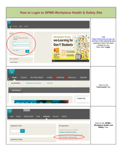
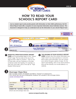
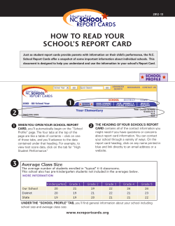


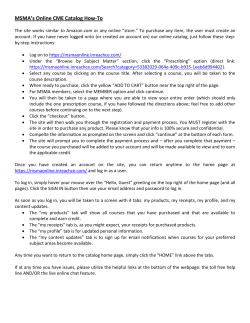


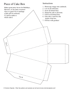

© Copyright 2026