
Lecture 18
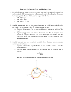
Homework (lecture 14): 1, 7, 8, 12, 14, 15, 20, 27, 29, 32, 37, 40, 47, 55, 56, 63, 68, 73 1. In the figure below, a circular loop of wire 10 cm in diameter (seen edge-on) is placed with its normal N at an angle = 30° with the direction of a uniform magnetic field B of magnitude 0.50 T. The loop is then rotated such that N rotates in a cone about the field direction at the rate 100 rev/min; angle remains unchanged during the process. What is the emf induced in the loop? d B dt B B.A. cos constant Therefore: 0 7. In the figure below, the magnetic flux through the loop increases according to the relation B = 6.0t2 + 7.0t, where B is in milliwebers and t is in seconds. (a) What is the magnitude of the emf induced in the loop when t = 2.0 s? (b) Is the direction of the current through R to the right or left? d B (a) Using Faraday’s law: dt | | (12t 7) 31(mV ) (b) B increases, using Lenz’s law, Binduced should be point into the page, so the current through R is to the left i 8. A uniform magnetic field B is perpendicular to the plane of a circular loop of diameter 12 cm formed from wire of diameter 2.5 mm and resistivity 1.69 x 10⁻⁸ .m. At what rate must the magnitude of B change to induce a 10 A current in the loop? l 2 0.06 8 R 1.69 10 1.3 10 3 () A 0.0025 2 4 1 d B r 2 dB i R R dt R dt dB iR 10 1.3 10 3 1.2(T / s) 2 2 dt r (0.06) 12. In Fig. 30-45, a wire loop of lengths L = 50.0 cm and W = 20.0 cm lies in a magnetic field B. What are the (a) magnitude and (b) direction (clockwise or counterclockwise-or "none“ if = 0) of the emf induced in the loop if 102 T / m) ykˆ ? What are B (4.00 2 ˆ .? What are (e) (c) and (d) the direction if B ( 6 . 00 10 T / s ) t k 2 and (f) the direction if B ( 8 . 00 10 T / m.s) ytkˆ ? What are (g) and (h) the direction if B (3.00 102 T / m.s) xtˆj ? What are (i) and (j) the direction if B (5.00 10 2 T / m.s) yt iˆ ? (a) zero; (b) none d B 0.06 0.5 0.20 0.006(V ) (c) dt (d) dB/dt increases, so the induced emf direction is clockwise 14. In Fig. 30-41a, a uniform magnetic field B increases in magnitude with time t as given by Fig. 30-41b. A circular conducting loop of area 8.0 x 10⁻⁴ m2 lies in the field, in the plane of the page. The amount of charge q passing point A on the loop is given in Fig. 30-41c as a function of t. What is the loop's resistance? d B dB A 0.003 A (V ) dt dt dq i 0.002 ( A) dt | | 0.003 8 10 4 R 0.0012() i 0.002 15. A square wire loop with 2.00 m sides is perpendicular to a uniform magnetic field, with half the area of the loop in the field as shown in the figure below. The loop contains an ideal battery with emf = 20.0 V. If the magnitude of the field varies with time according to B = 0.0420 - 0.870t, with B in tesla and t in seconds, what are (a) the net emf in the circuit and (b) the direction of the (net) current around the loop? (a) As time goes on, B decreases 2 d B L (0.87) 1.74(V ) dt 2 The induced B points out of the page, so the induced current as well as the induced emf is counterclockwise. (b) The net current is counterclockwise: net i 20. At a certain place, Earth's magnetic field has magnitude B = 0.590 gauss and is inclined downward at an angle of 70.0° to the horizontal. A flat horizontal circular coil of wire with a radius of 10.0 cm has 2500 turns and a total resistance of 85.0 . It is connected in series to a meter with 140 resistance. The coil is flipped through a half-revolution about a diameter, so that it is again horizontal. How much charge flows through the meter during the flip? d B dq ;i dt dt d B B | | dq dt i R dt R | d B | N | dq | BA cos ( BA cos ) R R 2 NBA cos 0 4 | dq | with 20 ; 1 gauss 10 T R 27. As seen in Fig. 30-49, a square loop of wire has sides of length 2.0 cm. A magnetic field is directed out of the page; its magnitude is given by B = 4.0t2y, where B is in teslas, t is in seconds, and y is in meters. At t = 2.5 s, what are the (a) magnitude and (b) direction of the emf induced in the loop? d B dt (a) l B BdA 4t 2 y (ldy) 4lt 2 ydy 2l 3t 2 d B 4l 3t dt 0 dA At t = 2.5 s: | | 4l 3t 8 10 5 (V ) (b) B increases, the current direction is clockwise, so the induced emf direction is clockwise 29. In Fig. 30-52, a metal rod is forced to move with constant velocity v along two parallel metal rails, connected with a strip of metal at one end. A magnetic field of magnitude B = 0.350 T points out of the page. (a) If the rails are separated by L = 25.0 cm and the speed of the rod is 55.0 cm/s, what emf is generated? (b) If the rod has a resistance of 18.0 and the rails and connector have negligible resistance, what is the current in the rod? (c) At what rate is energy being transferred to thermal energy? (a) (b) d B d ( BLvt ) BvL dt dt 0.35 0.55 0.25 0.048(V ) 0.048 3 i R 18 2.7 10 ( A) using Lenz’s law: the current direction is clockwise (c) P i 2 R 0.13(mW ) 32. A loop antenna of area 2.00 cm2 and resistance 5.21 is perpendicular to a uniform magnetic field of magnitude 21.0 T. The field magnitude drops to zero in 2.96 ms. How much thermal energy is produced in the loop by the change in field? d B B A 2110 6 2 10 4 6 | | 1.4 10 (V ) dt t 2.96 10 3 Ethermal i 2 Rt 2 R t 1.4 2 10 12 5.2110 6 2.96 10 3 1110 10 ( J ) 37. A long solenoid has a diameter of 12.0 cm. When a current i exists in its windings, a uniform magnetic field of magnitude B = 30.0 mT is produced in its interior. By decreasing i, the field is caused to decrease at the rate of 6.50 mT/s. Calculate the magnitude of the induced electric field (a) 2.20 cm and (b) 8.20 cm from the axis of the solenoid (see also Sample Problem 30-4, page 804) (a) (b) d B E.ds ; E.ds E 2r; B BA Br 2 dt r dB 2.2 10 2 E 6.5 10 3 7.15 10 5 (V / m) 2 dt 2 E.ds E 2r; B BA BR 2 R 2 dB 6.0 2 10 4 E 6.5 10 3 2r dt 2 8.2 10 2 1.43 10 4 (V / m) Figure 30-15 of Sample Problem 30-4 40. The inductance of a closely packed coil of 400 turns is 8.0 mH. Calculate the magnetic flux through the coil when the current is 12.0 mA. • B: magnetic flux • NB: magnetic flux linkage Li 8.0 10 3 12.0 10 3 B 2.4 10 7 (Wb) N 400 47. Inductors in series. Two inductors L1 and L2 are connected in series and are separated by a large distance so that the magnetic field of one cannot affect the other. (a) Show that the equivalent inductance is given by Leq = L1 + L2. (Hint: Review the derivations for resistors in series and capacitors in series. Which is similar here?) (b) What is the generalization of (a) for N inductors in series? di L L dt Consider two inductors in series: di di L1 L1 ; L2 L2 dt dt di Leq Leq ; Leq L1 L2 dt Leq L1 L2 55. A battery is connected to a series RL circuit at time t = 0. At what multiple of L will the current be 0.100% less than its equilibrium value? i 1 e t / L The equilibrium value: R iequil. Time at which: R i 0.999iequil. 0.999 R t 6.91 L t / L 1 e R Homework (lecture 15): 1, 2, 7, 9, 10, 17, 23, 25, 29, 32, 38, 41, 48, 53, 57, 62 1. An oscillating LC circuit consists of a 75.0 mH inductor and a 3.60 F capacitor. If the maximum charge on the capacitor is 2.90 C, what are (a) the total energy in the circuit and (b) the maximum current? q 2 Li 2 U U E U B 2C 2 (a) When q is maximum: 2 qmax U U E ,max 2C (b) i is maximum when q = 0: 2 Limax U B,max U E ,max 2 2. The frequency of oscillation of a certain LC circuit is 220 kHz. At time t = 0, plate A of the capacitor has maximum positive charge. At what earliest time t > 0 will (a) plate A again have maximum positive charge, (b) the other plate of the capacitor have maximum positive charge, and (c) the inductor have maximum magnetic field? q Q cos(t ) Determine from the conditions given in the problem, at t = 0: q Q cos i s maxi mum, so 0 (a) So, q is max again as T = (2/) x n T 2 LC 1 / f 4.6 10 6 (b) plate B has maximum positive charge at: (c) (s) 4.6(s) 1 t T (n 1)T t 2.3( s) 2 2 Q T (n 1) 2 UB sin (t ) UB max as t T 2C 4 2 t 1.15(s) 7. The energy in an oscillating LC circuit containing a 1.25 H inductor is 5.70 J. The maximum charge on the capacitor is 175 C. For a mechanical system with the same period, find the (a) mass, (b) spring constant, (c) maximum displacement, and (d) maximum speed. (a) mass m = 1.25 kg (b) spring constant k = 1/C Q2 Q 2 (175 10 6 ) 2 U C 2.69 10 3 ( F ) 2C 2U 2 5.7 10 6 1 k 372( N / m) 3 2.69 10 (c) xmax = 175 m = 1.75 x 10⁻⁴ (m) (d) Li 2 Q 2 Q i 3.02 10 3 ( A) 2 2C LC vmax 3.02 10 3 (m / s) 9. In an oscillating LC circuit with L = 50 mH and C = 4.0 F, the current is initially a maximum. How long will it take before the capacitor is fully charged for the first time? i I sin(t ) At t = 0, i is max: / 2 i I sin(t / 2) when the capacitor is fully charged, i = 0: t T t / 2 2 t T 2 4 T 2 LC 2 50 10 3 4 10 6 t 7 10 4 ( s) 4 4 4 10. LC oscillators have been used in circuits connected to loudspeakers to create some of the sounds of electronic music. What inductance must be used with a 3.4 F capacitor to produce a frequency of 10 kHz, which is near the middle of the audible range of frequencies? T 2 LC 1 / f L 1 4 2 f 2C 17. In Fig. 31-25, R = 14.0 , C = 6.20 F, and L = 54.0 mH, and the ideal battery has emf = 34.0 V. The switch is kept at a for a long time and then thrown to position b. What are the (a) frequency and (b) current amplitude of the resulting oscillations? (a) T 2 LC 1 / f f 1 2 LC (b) When the capacitor is fully charge (the switch is on a): Q C The maximum current when the switch is on b: I Q 2fQ 23. In an oscillating LC circuit, L = 25.0 mH and C = 7.80 F. At time t = 0 the current is 9.20 mA, the charge on the capacitor is 3.80 C, and the capacitor is charging. What are (a) the total energy in the circuit, (b) the maximum charge on the capacitor, and (c) the maximum current? (d) If the charge on the capacitor is given by q = Qcos(t + ), what is the phase angle ? (e) Suppose the data are the same, except that the capacitor is discharging at t = 0. What then is ? (a) t = 0: q 2 Li 2 U U E U B 2C 2 (b) the maximum charge: Q2 U U E ,max Q 2CU 2C (c) the maximum current: (d) the charge LI 2 U U B,max I 2 is given: At t = 0: q = 3.8 C q Q cos(t ) 2U L q cos 47 0 Q The capacitor is charging at t = 0: dq Q sin(t ) Q sin 0 dt 47 0 (d) if the capacitor is discharging: dq Q sin(t ) Q sin 0 dt 47 0 25. What resistance R should be connected in series with an inductance L = 220 mH and capacitance C = 12.0 F for the maximum charge on the capacitor to decay to 99.0% of its initial value in 50.0 cycles? (Assume ‘ ). q Qe Rt / 2L cos( ' t ) ' 2 ( R / 2 L) 2 We have: 1 / LC qmax e Rt / 2 L 0.99 Q t 50T 50 2 100 LC qmax 2 L qmax Rt / 2 L ln( )R ln( ) Q t Q 29. A 50.0 mH inductor is connected as in Fig. 31-10a to an ac generator with m = 30.0 V. What is the amplitude of the resulting alternating current if the frequency of the emf is (a) 1.00 kHz and (b) 8.00 kHz? iL I L sin(d t ) VL I L X L m X L d L 2fL m m IL X L 2f d L 32. An ac generator has emf = msindt, with m = 25.0 V and d = 377 rad/s. It is connected to a 12.7 H inductor. (a) What is the maximum value of the current? (b) When the current is a maximum, what is the emf of the generator? (c) When the emf of the generator is -12.5 V and increasing in magnitude, what is the current? m m 25 3 I 5 . 22 10 ( A) L (a) X L d L 377 12.7 iL I L sin(d t ) 2 (b) when iL is maximum, sin(d t ) 1 d t (2n 1) 2 m sin(d t ) 0 (c) 1 7 11 sin(d t ) d t 2n or d t 2n 2 6 6 d 7 md cos(d t ) 0 d t 2n dt 6 2 iL I L sin(2n ) 5.22 10 3 0.866 4.52 10 3 ( A) 3 38. The current amplitude I versus driving angular frequency d for a driven RLC circuit is given in Fig. 31-26. The inductance is 200 H, and the emf amplitude is 8.0 V. What are (a) C and (b) R? (a) The current I is maximum when: d 25 103 (rad / s) d 1 C LC (b) At resonance: 1 d2 L ZR m 8 RZ 2() I 4 41. In Fig. 31-7, set R = 200 , C = 70.0 F, L = 230 mH, fd = 60.0 Hz, and m = 36.0 V. What are (a) Z, (b) , and (c) I? (d) Draw a phasor diagram. Z R2 ( X L X C )2 X L XC tan R If > 0: m leads the current If < 0: the current leads m I m Z


© Copyright 2026