
Terminal Board 30 (TB30) - Siemens Industry Online Support
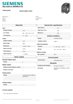
SINAMICS G130 Terminal Board 30 (TB30) Operating Instructions · 05/2010 SINAMICS s Terminal Board 30 (TB30) 1 ___________________ Safety information 2 ___________________ General SINAMICS SINAMICS G130 Terminal Board 30 (TB30) Operating Instructions Control version V4.3 SP2 05/2010 A5E01221269A 3 ___________________ Mechanical installation 4 ___________________ Electrical installation ___________________ 5 Technical specifications Legal information Legal information Warning notice system This manual contains notices you have to observe in order to ensure your personal safety, as well as to prevent damage to property. The notices referring to your personal safety are highlighted in the manual by a safety alert symbol, notices referring only to property damage have no safety alert symbol. These notices shown below are graded according to the degree of danger. DANGER indicates that death or severe personal injury will result if proper precautions are not taken. WARNING indicates that death or severe personal injury may result if proper precautions are not taken. CAUTION with a safety alert symbol, indicates that minor personal injury can result if proper precautions are not taken. CAUTION without a safety alert symbol, indicates that property damage can result if proper precautions are not taken. NOTICE indicates that an unintended result or situation can occur if the corresponding information is not taken into account. If more than one degree of danger is present, the warning notice representing the highest degree of danger will be used. A notice warning of injury to persons with a safety alert symbol may also include a warning relating to property damage. Qualified Personnel The product/system described in this documentation may be operated only by personnel qualified for the specific task in accordance with the relevant documentation for the specific task, in particular its warning notices and safety instructions. Qualified personnel are those who, based on their training and experience, are capable of identifying risks and avoiding potential hazards when working with these products/systems. Proper use of Siemens products Note the following: WARNING Siemens products may only be used for the applications described in the catalog and in the relevant technical documentation. If products and components from other manufacturers are used, these must be recommended or approved by Siemens. Proper transport, storage, installation, assembly, commissioning, operation and maintenance are required to ensure that the products operate safely and without any problems. The permissible ambient conditions must be adhered to. The information in the relevant documentation must be observed. Trademarks All names identified by ® are registered trademarks of the Siemens AG. The remaining trademarks in this publication may be trademarks whose use by third parties for their own purposes could violate the rights of the owner. Disclaimer of Liability We have reviewed the contents of this publication to ensure consistency with the hardware and software described. Since variance cannot be precluded entirely, we cannot guarantee full consistency. However, the information in this publication is reviewed regularly and any necessary corrections are included in subsequent editions. Siemens AG Industry Sector Postfach 48 48 90026 NÜRNBERG GERMANY A5E01221269A Ⓟ 08/2010 Copyright © Siemens AG 2010. Technical data subject to change Table of contents 1 Safety information...................................................................................................................................... 7 1.1 Warnings ........................................................................................................................................7 1.2 Safety and operating instructions...................................................................................................8 1.3 Components that can be destroyed by electrostatic discharge (ESD) ..........................................9 2 General.................................................................................................................................................... 11 3 Mechanical installation............................................................................................................................. 13 4 Electrical installation ................................................................................................................................ 15 5 Technical specifications........................................................................................................................... 21 Terminal Board 30 (TB30) Operating Instructions, 05/2010, A5E01221269A 5 Table of contents 6 Terminal Board 30 (TB30) Operating Instructions, 05/2010, A5E01221269A Safety information 1.1 1 Warnings WARNING Hazardous voltages are present when electrical equipment is in operation. Severe personal injury or substantial material damage may result if these warnings are not observed. Only qualified personnel are permitted to work on or around the equipment. This personnel must be thoroughly familiar with all the warnings and maintenance procedures described in these operating instructions. The successful and safe operation of this device is dependent on correct transport, proper storage and installation, as well as careful operation and maintenance. National safety guidelines must be observed. DANGER Five safety rules When carrying out any kind of work on electrical devices, the "five safety rules" defined in EN 50110 must always be observed: 1. Disconnect the system. 2. Protect against reconnection. 3. Make sure that the equipment is de-energized. 4. Ground and short-circuit. 5. Cover or enclose adjacent components that are still live. NOTICE For a UL-approved system use 60/75°C copper conductors only. Terminal Board 30 (TB30) Operating Instructions, 05/2010, A5E01221269A 7 Safety information 1.2 Safety and operating instructions 1.2 Safety and operating instructions DANGER This equipment is used in industrial high-voltage installations. During operation, this equipment contains rotating and live, bare parts. For this reason, they could cause severe injury or significant material damage if the required covers are removed, if they are used or operated incorrectly, or have not been properly maintained. When the machines are used in non-industrial areas, the installation location must be protected against unauthorized access (protective fencing, appropriate signs). Prerequisites Those responsible for protecting the plant must ensure the following: ● The basic planning work for the plant and the transport, assembly, installation, commissioning, maintenance, and repair work is carried out by qualified personnel and/or checked by experts responsible. ● The operating manual and machine documentation are always available. ● The technical specifications regarding the applicable installation, connection, environmental, and operating conditions are always observed. ● The plant-specific assembly and safety guidelines are observed and personal protection equipment is used. ● Unqualified personnel are forbidden from using these machines and working near them. This operating manual is intended for qualified personnel and only contain information and notes relating to the intended purpose of the machines. The operating manual and machine documentation are written in different languages as specified in the delivery contracts. Note We recommend engaging the support and services of your local Siemens service center for all planning, installation, commissioning and maintenance work. 8 Terminal Board 30 (TB30) Operating Instructions, 05/2010, A5E01221269A Safety information 1.3 Components that can be destroyed by electrostatic discharge (ESD) 1.3 Components that can be destroyed by electrostatic discharge (ESD) CAUTION The board contains components that can be destroyed by electrostatic discharge. These components can be easily destroyed if not handled properly. If you do have to use electronic boards, however, please observe the following: You should only touch electronic boards if absolutely necessary. When you touch boards, however, your body must be electrically discharged beforehand. Boards must not come into contact with highly insulating materials (such as plastic parts, insulated desktops, articles of clothing manufactured from man-made fibers). Boards must only be placed on conductive surfaces. Boards and components should only be stored and transported in conductive packaging (such as metalized plastic boxes or metal containers). If the packaging material is not conductive, the boards must be wrapped with a conductive packaging material (such as conductive foam rubber or household aluminum foil). The necessary ESD protective measures are clearly illustrated in the following diagram: ● a = conductive floor surface ● b = ESD table ● c = ESD shoes ● d = ESD overall ● e = ESD wristband ● f = cabinet ground connection ● g = contact with conductive flooring d d b b e e f g a c f f c 6LWWLQJ Figure 1-1 d a 6WDQGLQJ f f g c a 6WDQGLQJVLWWLQJ ESD protective measures Terminal Board 30 (TB30) Operating Instructions, 05/2010, A5E01221269A 9 Safety information 1.3 Components that can be destroyed by electrostatic discharge (ESD) 10 Terminal Board 30 (TB30) Operating Instructions, 05/2010, A5E01221269A 2 General Description The TB30 Terminal Board supports the addition of digital inputs/digital outputs and analog inputs/analog outputs to the Control Unit. The following are located on the TB30 Terminal Board: ● Power supply for digital inputs/digital outputs ● 4 digital inputs ● 4 digital outputs ● 2 analog inputs ● 2 analog outputs The TB30 Terminal Board plugs into the option slot on the Control Unit. A shield connection for the signal cable shield is located on the Control Unit. Figure 2-1 Terminal Board TB30 Terminal Board 30 (TB30) Operating Instructions, 05/2010, A5E01221269A 11 General 12 Terminal Board 30 (TB30) Operating Instructions, 05/2010, A5E01221269A 3 Mechanical installation CAUTION The Option Board should only be inserted and removed when the Control Unit and Option Board are disconnected from the power supply. /RRVHQWKH UHWDLQLQJVFUHZV RIWKH2SWLRQ%RDUG 7RU[7 5HWDLQLQJVFUHZV 01P Figure 3-1 :LWKGUDZWKH 2SWLRQ%RDUG Mounting the Option Board Terminal Board 30 (TB30) Operating Instructions, 05/2010, A5E01221269A 13 Mechanical installation 14 Terminal Board 30 (TB30) Operating Instructions, 05/2010, A5E01221269A 4 Electrical installation Interface overview 7% ; 3RZHUVXSSO\IRU 'LJLWDORXWSXWV ; 'LJLWDOLQSXWVRXWSXWV ; $QDORJLQSXWVRXWSXWV Figure 4-1 Interface description of the TB30 Terminal Board 30 (TB30) Operating Instructions, 05/2010, A5E01221269A 15 Electrical installation Connection overview ([W b9 0 0 ; 9 0 0 0 0 7HUPLQDO%RDUG7% ; ', ', ', '2 '2 ', '2 '2 ; sbb $, $, $, 9 $, $2 9 Figure 4-2 16 $2 $2 $2 Connection overview TB30 Terminal Board 30 (TB30) Operating Instructions, 05/2010, A5E01221269A Electrical installation X424 power supply, digital outputs Table 4- 1 Terminal block X424 Terminal Function Technical specifications + Power supply + Power supply M Chassis ground Voltage: 24 V DC (20.4 V - 28.8 V) Current consumption: Max. 4 A (per digital output max. 0.5 A) M Chassis ground Max. current via jumper in connector: 20 A at 55 °C Max. connectable cross-section: 2.5 mm2 Note The two "+" and "M" terminals are jumpered in the connector. This ensures that the supply voltage is looped through. This power supply is required for the digital outputs only. The electronic power supply and the power supply for the analog inputs/outputs are drawn via the option slot of the Control Unit. Note The power supply of the digital outputs and the electronics power supply of the Control Unit are optically isolated. Note If a the 24 V supply is briefly interrupted, then the digital outputs are deactivated during this time. Terminal Board 30 (TB30) Operating Instructions, 05/2010, A5E01221269A 17 Electrical installation Digital inputs/outputs X481 Table 4- 2 Terminal strip X481 Terminal Designation1) Technical specifications 1 DI 0 2 DI 1 3 DI 2 4 DI 3 Voltage: - 3 V to 30 V Current consumption: 10 mA at 24 V DC Ground reference: X424. M Input delay: - for "0" to "1": 20 μs - for "1" to "0": 100 μs Level (incl. ripple) High level: 15 V to 30 V Low signal level: -3 V to 5 V 5 DO 0 6 DO 1 7 DO 2 8 DO 3 Voltage: 24 V DC Max. load current per output: 500 mA Ground reference: X424.M Sustained short-circuit-proof Output delay: - for "0" to "1": Typically 150 μs at 0.5 A ohmic load (500 μs maximum) - for "1" to "0": Typically 50 μs at 0.5 A ohmic load Max. connectable cross-section: 0.5 mm2 1) DI: Digital input, DO: Digital output Note An open input is interpreted as "low". The power supply and the digital inputs/outputs are optically isolated from the Control Unit. Note If a the 24 V supply is briefly interrupted, then the digital outputs are deactivated during this time. 18 Terminal Board 30 (TB30) Operating Instructions, 05/2010, A5E01221269A Electrical installation Analog inputs/outputs X482 Table 4- 3 Terminal strip X482 Terminal Designation1) Technical specifications 1 AI 0+ 2 AI 0- 3 AI 1+ 4 AI 1- Analog inputs (AI) Voltage: -10 V to +10 V Inner flow resistance: 65 kΩ Resolution: 13 bit + sign 5 AO 0+ 6 AO 0- 7 AO 1+ 8 AO 1- Analog outputs (AO) Voltage range: -10 V to +10 V Load current: max. -3 mA to +3 mA Resolution: 11 bit + sign Continuously short-circuit proof Max. connectable cross-section: 0.5 mm2 1) AI: Analog input, AO: Analog output Note An open input is interpreted as approximately "0 V". The power supply of the analog inputs/outputs is drawn via the option slot of the Control Unit and not via X424. The shield is connected to the Control Unit. CAUTION The common-mode range must not be violated. The analog differential voltage signals can have a maximum offset voltage of +/-30 V with respect to the ground potential. If the range is violated, incorrect results may occur during analog/digital conversion. Terminal Board 30 (TB30) Operating Instructions, 05/2010, A5E01221269A 19 Electrical installation Shield connection of the TB30 on the Control Unit CU320 6KLHOGFRQQHFWLRQRQ WKHFRQWUROXQLW 01P ; $QDORJLQSXWV RXWSXWV Figure 4-3 TB30 shield connection The permissible bending radii for the cables must not be exceeded when the cables are being installed. 20 Terminal Board 30 (TB30) Operating Instructions, 05/2010, A5E01221269A 5 Technical specifications General technical specifications Table 5- 1 General technical specifications Product standard EN 61800-5-1 Technical specifications Table 5- 2 Technical data Unit Value Voltage VDC 24 DC (20.4 – 28.8) Current via the option slot of the CU (without digital outputs) ADC 0.05 Power loss W <3 Reaction time The reaction time of digital inputs/outputs and analog inputs/outputs depends on the evaluation on the Control Unit (see function diagrams FP 9100 - FP 9106) in the SINAMICS list manual). Weight kg Electronic power supply Terminal Board 30 (TB30) Operating Instructions, 05/2010, A5E01221269A 0.1 21 Technical specifications 22 Terminal Board 30 (TB30) Operating Instructions, 05/2010, A5E01221269A Siemens AG Industry Sector Drive Technologies Large Drives Postfach 4743 90025 NUREMBERG GERMANY www.siemens.com/automation Subject to change © Siemens AG 2010


© Copyright 2026