
REPAIR PRODUCTS
REPAIR
PRODUCTS
for Natural Gas
Piping Systems
• Collar Clamps & Bell Joint Clamps
• Band Clamps & 360-Degree Clamps
• High Pressure Clamps
• Split Repair Sleeves
• High Pressure Repair Sleeves
• Reinforcing Sleeves
• Encasement Sleeves
Applicable Warnings
When pipe pullout
could occur, pipe joint
MUST be anchored.
Failure to anchor pipe
joint could result in
escaping line content
that could cause
property damage,
serious injury or death.
Piping Specialties, Dresser, Inc.
41 Fisher Avenue, Bradford, PA 16701
Phone: (814) 362-9200
Fax: (814) 362-9344
Email: [email protected]
© 2009 Dresser, Inc.
www.dresser.com/pipingspecialties
FORM 0200G
REV. 11.09/S1.5M
Piping Specialties
Gas
Repair
Products
Table
of
Contents
Defect/Repair Product
Guidelines ...............................................................................Pages 1-3
Product Line
Style
Page
Repair Clamps
Collar Leak Clamps for Steel 3/4” - 12” .............................................................4/41....................... 4
Bell Joint Clamps for Cast Iron 3” - 48” . ..........................................................60/160..................... 5
High Pressure PermaClamp 4” - 24” ....................................................................75........................ 6
Band Clamp 2” - 12” . ...........................................................................................77........................ 7
HANDIBAND Clamps 1/2” - 8” ............................................................................118....................... 8
360-Degree Clamps 2” - 24” ...............................................................................360....................... 9
Repair Sleeves
Pipe Repair & Tapping Split Sleeves.......................................................................50...................... 10
Split Repair Sleeves for Steel 2”, 3”, 4” . .............................................................54, 73................... 11
Readypack Sleeves for Cast Iron.............................................................................80...................... 12
Innerpak Sleeves for High Pressure Steel................................................................93...................... 13
Innerpak Sleeves for High Pressure Steel - Expanded Body....................................96...................... 14
Other DRESSER® Products for Gas Piping Systems
Prefabricated Gate Stations
Dresser® utilizes its unique combination of
engineering expertise and custom fabrication
capabilities to produce truly “cost effective”
prefabricated modular meter sets and gas
transmission & regulation gate stations. Our
prefabricated sets significantly reduce field
installation costs by lowering material and
labor costs required for field pipe cutting,
beveling, welding, threading, coating and testing.
Prefabricated gate stations are custom-built to
customer specifications and configurations and
offer a variety of valving options to suit your
particular M&R system requirements.
Excess Flow Valves
The safe, economical choice for safety in the event of a catastrophic line rupture.
When a damaged service line allows natural gas leakage into residential or commercial
buildings, both lives and property are at risk. Dresser developed its Excess Flow Device to reduce
that risk by restricting gas flow automatically when a service line flow condition exceeds the
normal operating flow such as would occur with third party damage.
Each Dresser® Excess Flow Device is factory-tested to assure it performs within the designated
trip flow and bypass flow range and complies with CFR Title 49 D.O.T. 192.381 and MSS-SP-115
governing standards. Fusion, weld and mechanical configurations are available factory-integrated
in a variety of carrier fittings. Manufactured for 10 - 60 psi service applications. Consult factory for
other pressure ratings.
Repair Sleeves for High Pressure Pipelines............................................................97...................... 15
Reinforcing Sleeves for Welded Joints...............................................................110, 115............16-17
Hot Tap and Line Stop Fittings
Reinforcing Sleeves - Encasement.........................................................................220................18-19
Dresser® manufactures hot tapping and line stop fittings and accessories for the natural gas, oil
and chemical industries. LS-2 Pressure Control Fittings are available for steel piping systems
in threaded sizes from 1/4” through 3” and flange fittings from 4” through 12”.
Full-encirclement Line Stop fittings are available in ANSI 150, 300, 600 and 900 Series
from 4” through 48” sizes. Split sleeve fittings are also manufactured with side outlet, spherical
configurations and with a plain raised face weld neck flange for hot tapping. Line Stop Flanges
and Completion Plugs are also available. LS-2 Pressure Control Fittings and Line Stop Fittings
are compatible with specific tapping and plugging equipment and are designed to carry the extra
loads imposed during hot tapping and line stopping operations. All fittings meet DOT 192 Federal
Regulation for gas pipelines; and DOT 195 Federal Regulation for liquid pipelines and most international codes.
Shown here is a Dresser Style 50 mechanical
Reinforcing Sleeves for Small Diameter Welds & Couplings................................ 220S.................... 19
PBR Pressure Balanced Repair Sleeve.............................................................................................. 20
Tap-N-Valve™ Tee............................................................................................................................. 21
Bell-Pack Sleeves for Bell & Spigot Joints.............................................................126..................... 22
“Hot Line” Insulating Sleeves for Steel...................................................................850..................... 23
Dresser Gaskets....................................................................................................... 24
www.dresser.com/pipingspecialties
NEVER INSTALL ANY DRESSER PRODUCTS
BEFORE READING THE INSTALLATION INSTRUCTIONS
AND WARNINGS!
Hot tap fittings are easily integrated with a
variety of Dresser mechanical products.
•Pre-engineered configurations
• Custom-fabricated to your specs and requirements
• Ideally suited for cast-iron piping applications
•Eliminates the need for field welding
•Factory-tested, factory-coated
split sleeve with a Blackhawk 150# LS-2 weld
fitting with side outlet, and a Dresser Style
711 coupling for PE transition connection.
DRESSER
®
Life-time Gaskets
Dresser Compounded Rubber Gaskets
Pipe joints must be able to absorb pipe stress caused by natural
forces and natural expansion, contraction, vibration and deflection
while the line is in service. The sealing capabilities and the extreme
flexibility of a Dresser coupled joint is made possible by the resilience
of the rubber-compounded gaskets. Resiliency is the property that
enables the gaskets to maintain pressure against the followers that
confine it and, at the same time, allow for flexibility not found in rigid
piping connections. Without it, a flexible joint is not possible!
Simply put, the absorption of pipeline stress permits each section
of the pipeline to “float” in the joint ensuring a flexible piping system
while avoiding leakage, line breaks, costly repairs and service
interruptions.
Buna S (Grade 27) Max. Temp. 212°F*
The compound most generally used for plain gaskets is Buna S
(Grade 27). This gasket has wide applications and is accepted as
standard for most pipeline use. It is recommended for use on lines
transporting both fresh water and salt water, natural and other gases, air,
most acids, alkaline and sugar solutions and some refrigerants.
Buna N (Grade 42 - Nitrile) Max. Temp. 212°F*
Buna N (Grade 42) gaskets are resistant to oil, most aromatic and
aliphatic hydrocarbons, natural gas fogging oil, condensates and
gasolines.
Armored® Gaskets
Armored gaskets can be used to great advantage where low
electrical-resistant joints are desired. The armor “bites” into the pipe
providing metal to metal contact allowing easy passage of current where
cathodic protection is a necessity.
The armor–an elastic, practically indestructible brass coil or helix–is
molded into the gasket tip becoming an integral part of the gasket. When
used with the proper grade/compound rubber, the armor shields the
gasket material from the line content without interfering with the sealing
efficiency of the gasket.
DRESSER Repair Products for Steel Pipe Sizes
Fluorocarbon - Max. Temp. 350°F
Fluorocarbon gaskets are resistant to hydrocarbons, aromatic
hydrocarbons, alcohols, organic acids, nitrogen-containing
compounds, vegetable oils and greases.
Butyl -Max. Temp. 250°F
Butyl gaskets are resistant to hot air service, steam, hot water and
miscellaneous aqueous solutions. They are also suitable for vegetable
oils, organic chemicals, oxidizing acids and alkalies.
EPDM - Max. Temp. 300°F
EPDM gaskets provide excellent resistant to aging factors such as
ozone, oxygen and elevated temperatures. This includes service in hot
water, steam and dry heat. They are also suitable for handling popular
chemicals such as ketones, alcohols, phosphate ester hydraulic fluids,
glycols, dilute acids and alkalies.
A. Longitudinal Breaks up to 8” or
B. Circumferential Breaks
High Temperature - Max. Temp. 1200°F
These braided flexible gaskets are designed specifically for the high
temperature and abrasive atmospheres associated with services such
as fly ash handling systems. As a replacement for asbestos, these
gaskets are manufactured of a pure homogenous graphite bonded to
a fiberglass carrier for strength and thermal durability. The braid over
braid construction is die-formed and cut to length to fit proper
coupling configurations resulting in a uniform tolerance which has
proven itself as a reliable asbestos replacement.
Note: The non-resilient characteristic of this particular gasket material
may result in a non leak-proof seal. This should be taken into
consideration for this application.
PRODUCT
54 Split Sleeve 73 Split Sleeve
93 Split Sleeve 96 Split Sleeve 97 Split Sleeve 360 Clamp SIZE
MAX. PRESS.
2”- 4”
2” & 3” 6” - 24” 6” - 24” 3” - 16” 500 psi
500 psi
500 psi
500 psi
1480 psi
2”- 12” 14”- 24” See Chart
Page 9
WARNING NOTE: Temperature recommendations are for reference purposes
only. Please consult Dresser Engineering for specific recommendations,
product style, line content, working pressure and temperature ranges.
D. Small Pinhole Leaks, Splits, or
Corrosion Cracks or; E. Broken Weld
PRODUCT
54 Split Sleeve 73 Split Sleeve
75 Clamp
77 Band Clamp 93 Split Sleeve 118 Handiband Clamp (D only)
360 Clamp (D only)
SIZE
MAX. PRESS.
2”- 4”
2” & 3” 4”- 36” 1”- 24”
6” - 24” 1/2”- 4”
6”- 8”
2”- 12” 14”- 24” 500 psi
500 psi
1200 psi
150 psi
500 psi
150 psi
100 psi
See Chart
Page 9
*For Dresser Styles 65 & 88 Fittings, the maximum temperature is 150°F
Dresser Gasket Recommendations for SEVERE Service Conditions
®
LINE
CONTENT
Acetic Acid
(10% concentration)
Ammonium Chloride
Ammonium Phosphate
(diabasic)
Ammonium Phosphate
(monobasic)
Barium Chloride
Barium Hydroxide
Benzene
Boric Acid
Butyl Acetate
24
Calcium Bisulfite
Calcium Chloride
Carbolic Acid, Phenol
Carbon Dioxide, Wet
Carbon Tetrachloride
Citric Acid
Copper Cyanide Copper Sulfate
DRESSER
GASKET
Plain Gr. 27
Plain Gr. 27
Plain Gr. 27
Plain Gr. 27
Plain Gr. 27
Plain Gr. 27
Armored Gr. 42
Plain Gr. 27
Armored Gr. 42
Plain Gr. 27
Plain Gr. 27
Plain Gr. 27
Plain Gr. 27
Plain Gr. 42
Plain Gr. 27
Plain Gr. 27
Plain Gr. 27
LINE
CONTENT
DRESSER
GASKET
Ethylene Dichloride
Ethylene Glycol
Ferric Chloride
Ferric Sulfate
Formaldehyde
Formic Acid
Gelatin
Hydrogen Peroxide
Armored Gr. 27
Plain Gr. 27
Plain Gr. 27
Plain Gr. 27
Plain Gr. 27
Plain Gr. 27
Plain Gr. 27
Plain Gr. 42
Lacquers
Magnesium Chloride
Nickel Sulfate
Oxalic AcidPlain Gr. 42
Phosphoric Acid
Picric Acid
Potassium Hydroxide
Potassium Sulfate
Puric Acid
Armored Gr. 42
Plain Gr. 27
Plain Gr. 27
Sodium Bicarbonate
(baking soda)
Plain Gr. 27
Plain Gr. 42
Plain Gr. 42
Plain Gr. 27
Plain Gr. 42
Plain Gr. 27
LINE
CONTENT
Sodium Metaphosphate
Sodium Perborate
Sodium Phosphate
(monobasic, dibasic,
tribasic)
Sodium Sulfate
Sodium Thiosulfate
(hypo)
Soybean Oil
Stearic Acid
Styrene
Tannic AcidPlain Gr. 27
Tartaric Acid
Trichloroethylene
Vinegar
Vinyl Chloride
Zinc Chloride
DRESSER
GASKET
Plain Gr. 27
Plain Gr. 27
Plain Gr. 27
Plain Gr. 27
Plain Gr. 27
Plain Gr. 42
Plain Gr. 42
Viton®
Plain Gr. 27
Armored Gr. 42
Plain Gr. 27
Plain Gr. 27
Plain Gr. 27
Leaking Collars
PRODUCT
SIZE
4 Collar Clamp
3/4”- 4”
41 Collar Clamp 4-1/2”- 12” 54 Split Sleeve 2”- 4”
73 Split Sleeve
2” & 3” 93 Split Sleeve 6” - 24” 96 Split Sleeve 6” - 24” MAX. PRESS.
1000 psi
1000 psi
500 psi
500 psi
500 psi
500 psi
Leaking Coupled Joints
PRODUCT
SIZE
MAX. PRESS.
54 Split Sleeve 2”- 4”
500 psi
96 Split Sleeve 6” - 24” 500 psi
220 Sleeve
2” - 26” 400 -1600 psi
See Chart Pg. 18
Questions? Call Dresser Customer Service: 1-814-362-9200
1
Style 850 Insulating Sleeve
DRESSER Repair Products for Cast Iron Pipe Sizes
The Dresser® Style 850 Insulating Sleeve is extensively used by gas utilities to simplify the
application of cathodic protection to existing steel mains. The Style 850 is used with a conventional tapping machine equipped with a shell cutter or a hole saw to completely sever the main
inside the sleeve. One end of the 850 is effectively insulated from the main by means of high
dielectric insulators, while the other end is conductive, tying the sleeve into the existing section
of the main under cathodic protection. A stabilizing rib in the sleeve body accurately centers the
850 on the main and prevents any excessive end-pitch of the pipe after the cutting operation.
For hot-tapping existing
gas mains for
cathodic protection
Longitudinal Breaks up to 8”
PRODUCT
SIZE
360 Clamp Longitudinal Breaks from 8-16”
MAX. PRESS.
PRODUCT
SIZE
MAX. PRESS.
100 psi
150 psi
50 Special 4” and above
100 psi
360 Clamp 3”- 8” 10”- 24” See Chart
Page 9
50 Split Sleeve 4” and above
80 Split Sleeve 4” - 8” 3”- 8” 10”- 24” See Chart
Page 9
• Eliminates the need for expensive by-pass equipment
• No service interruptions (Hot-tapped)
• Sleeves come completely factory-assembled for quick installation
• A gas-tight, permanent joint! 3” Style 850
4” Style 850
Style 850 Insulating Sleeve Specifications
Nominal
Size*
(In.)
2
3
4
6
Outside
Diameter
OD (In.)
Overall
Length
(In.)
Item
Code
Approx.
Shipping
Weight
(Lbs.)
2.375
3.500
4.500
6.625
11-1/2
15-1/2
17-1/2
20-3/8
0005
0002
0003
0004
38
125
200
325
* All sizes rated to 125 psi
Circumferential Breaks
PRODUCT
SIZE
50 Split Sleeve 4” and above
80 Split Sleeve 2” - 6” 360 Clamp 2
©2009 Dresser, Inc.
3”- 8” 10”- 24” MAX. PRESS.
100 psi
150 psi
See Chart
Page 9
Small Pinhole or Corrosion Leaks
PRODUCT
SIZE
50 Split Sleeve 4” and above
80 Split Sleeve 2” - 6” 360 Clamp 3”- 8” 10”- 24” MAX. PRESS.
100 psi
150 psi
See Chart
Page 9
Materials of Construction
Body: Ductile Iron to ANSI/SAE J434, Grade D4512; ASTM
A536 Grade 65-45-12
Followers (4”) : Carbon Steel, Malleable or Ductile Iron
per size specs.
Bolts, Nuts & Set Screws: Carbon Steel
Gasket Seals: To Dresser Specs per application
Insulator: Dielectric Plastic
Conductor: Copper
2” Style 850 Sleeve w/Cap
©2009 Dresser, Inc.
23
Style 126 Bell-Pack® Sleeves
Pipeline maintenance personnel avoid pipeline shutdowns and expensive, temporary
makeshift repairs by installing the Dresser® Style 126 Repair Sleeve for a fast,
economical and permanent repair. A sleeve of lighter weight and compact design, the Style
126 provides maximum inside dimension clearance for repairing split cast iron bells and
leaking mechancial joints.
Built to rigid Dresser specifications, Style 126 repair sleeves
provide the time-proven features of the Dresser rubber-packed
gasket sealing design. Side bolts, which are fully enclosed
within the sleeve body to prevent corrosion, are tightened
to compress side gaskets providing a complete, permanent
leakproof seal.
For repair of broken
cast iron bell & spigot joints
Materials of Construction
Body: Cast or malleable iron
Vent Plug: Forged steel to ASTM A105
or Cast to ASTM A126-42 Class A
Followers: Cold-formed carbon steel
Bolts: Alloy to AWWA C111/ANSI A21.11
Gaskets: Grade 29
Set Screws: Carbon steel, cadium plated
Coating: Dresser shopcoat standard;
Fusion-bonded epoxy optional
PRODUCT
Specifications for Sizes 3” thru 24” (100 PSI)
Nominal
Size
(CIP)
Outside
Diamater
(OD)
End Screws1
Number
Diam. x Length
A & B
Short Side Bolts
Number 2
Diam. x Length
C
Long Side Bolts
Number
Diam. x Length
D
Inside
Dimensions
Diam. Length
(E) (F)
Overall
Dimensions
Diam. Length
(H)
(G)
Max.
Press.
PSI
Weight
Shipping
Each
(Lbs.)
19-1/16
19-1/16
1
1
100
100
123
123
3.800
3.960
12—3/8 x 1
12—3/8 x 1
6—5/8 x 4
6—5/8 x 4
4—5/8 x 5-1/2
4—5/8 x 5-1/2
8-1/2
8-1/2
12
12
4
4
4.800
5.000
12—3/8 x 1
12—3/8 x 1
6—5/8 x 4
6—5/8 x 4
4—5/8 x 6
4—5/8 x 6
10
10
12
12
14-1/2 19-1/16
14-1/2 19-1/16
1
1
100
100
136
136
6
6
6.900
7.100
16—3/8 x 1
16—3/8 x 1
6—5/8 x 5
6—5/8 x 7
4—5/8 x 7
4—5/8 x 7
12-1/2 12
12-1/2 12
17-1/8 19-1/16
17-1/8 19-1/16
1
1
100
100
185
185
8
8
9.050
9.300
20—3/8 x 1-1/4
20—3/8 x 1-1/4
6—5/8 x 5
6—5/8 x 5
4—5/8 x 7-1/2 15-1/2 12-3/8 20-1/419-13/16 1
4—5/8 x 7-1/2 15-1/2 12-3/8 20-1/419-13/16 1
100
100
265
265
10
10
11.100
11.400
24—7/16 x 2-1/4
24—7/16 x 2-1/4
12—3/4 x 4
12—3/4 x 4
-
-
16-5/8 13-1/2 22-3/8 18-5/8
16-5/8 13-1/2 22-3/8 18-5/8
1
1
100
100
300
300
12
12
13.200
13.500
28—7/16 x 2-1/4
28—7/16 x 2-1/4
12—7/8 x 4
12—7/8 x 4
-
-
18-3/4 13-1/2 24-1/2 18-5/8
18-3/4 13-1/2 24-1/2 18-5/8
1
1
100
100
335
335
16
16
17.400
17.800
32—7/16 x 2-1/4
32—7/16 x 2-1/4
14—7/8 x 4
14—7/8 x 4
-
-
24
24
16
16
30
30
21-1/8
21-1/8
2
2
100
100
554
554
20
20
21.600
22.060
40—7/16 x 2-1/4
40—7/16 x 2-1/4
14— 1 x 4
14— 1 x 4
-
-
30
30
17
17
36
36
22-1/8
22-1/8
3
3
100
100
770
770
24
24
25.800
26.320
48—7/16 x 2-1/4
48—7/16 x 2-1/4
14— 1 x 4
14— 1 x 4
-
-
39-7/8 23-1/8
39-7/8 23-1/8
3
3
100
100
853
853
33-7/8 18
33-7/8 18
13
13
Vent 3
Diam.
3
3
1- End Scews are cadium-plated high-grade steel, and have square heads, 3/8” across flats.
2- Side Bolts are cadium-plated high-grade steel with track heads and rolled threads through 8” size. Larger sizes are supplied with galvanized machine bolts.
3- Vent supplied with iron pipe threads or corporation threads, if specified.
©2009 Dresser, Inc.
SIZE
MAX. PRESS.
60 Bell Clamp
3” - 24”
60-S Bell Clamp 4” - 24”
160 Bell Clamp
4” - 8”
12” & 16”
100 psi
100 psi
100 psi
126 Split Sleeve 3” - 24”
100 psi
22
Leaking Inner-Tite Joint
Cracked or Leaking Bell
Style 126
PIPE
DRESSER Repair Products for Cast Iron Pipe Sizes
PRODUCT
60-S Bell Clamp
SIZE
126 Split Sleeve 3” - 24”
MAX. PRESS.
100 psi
MAX. PRESS.
4” - 24”
100 psi
126 Split Sleeve 8”, 20”, 24”
100 psi
126 Special
100 psi
4’’, 6”, 10” 16’’, 30”, 36”
Leaking Mechanical Joints
Leaking Coupled Joints
PRODUCT
SIZE
PRODUCT
SIZE
126 Split Sleeve 3” - 24”
MAX. PRESS.
100 psi
OPTIONAL REPAIR
Remove defective length of pipe, insert
new pipe and join with two Dresser Style 38,
40 or 700 couplings.
©2009 Dresser, Inc.
3
Style 4 & 41 Collar Clamps
Stops all leaks
through screw collars
Style 90 Tap-N-Valve Tees for Pressure Relief
Dresser® Style 4 and Style 41 clamps quickly and inexpensively stop leaks through the
threads of screw collars (threaded couplings), solvent weld couplings (collars) and stab-type
PVC joints. Repairs are permanent and normally made without interrupting service or dismantling the line. Style 4 clamps consists of two malleable split follower rings with interlocking
ends on each section, two
resilient split Dresser gaskets,
and bolts as required for pipe
sizes up to 4”.
Style 41 consists of the
same parts except the split
follower rings are steel and
are connected by steel lock
links.
Use When Installing Dresser Reinforcing Sleeves
Dresser® time-proven Style 90 Tap-N-Valve Tees can be used for effective
pressure relief when installing Dresser Styles 110, 115 and 220 reinforcing sleeves. As
an option, the Style 90 tee is simply welded to the reinforcing sleeve, then tapped
through the sleeve body to depressurize the sleeve while repair is being made.
As illustrated in View I, the tee is supplied with a splatter cap to prevent splatter from
entering the internal threads of the tapping device. Field contouring of the tee weld inlet
in also recommended to reduce the potential for field weld “burn through” and internal
weld splatter. Leave weld splatter cap in place to prevent slag from entering threads.
To make the tap, the hollow cutting end of the tapping tool is inserted in the top of the tee
and the threads engaged. A hex bar and 14” ratchet wrench are then used to rotate the
tapping tool in a clockwise direction until the cutting edge touches the sleeve. As tip of
tool penetrates through the sleeve wall, the required wrench pull or torque will decrease.
Once the tap is complete, the tool is seated and the slug of the sleeve is retained in the
tool (View II) . The wrench is then rotated in a counter-clockwise direction until the tool is
flush with the top of the tee body.
Materials of Construction
Followers: AISI C1012 or ASME SA36
Bolts & Nuts: Alloy to AWWA C 111/ANSI A21.11
Gasket:
Grade 27 BUNA S
Style 4 (Malleable)
Sizes Specifications for 3/4” through 4”
Nominal
Size Steel
(ID)
3/4
1
1-1/4
1-1/2
2
2-1/2
3
4-1/4 CAS
4
Outside
Diameter
(OD)
1.050
1.315
1.660
1.900
2.375
2.875
3.500
4.500
4.500
COLLAR DIMENSIONS
Overall
Overall
Diameter (A) Length (B)
1.316
1.575
2.054
2.294
2.841
3.389
4.014
5.021
5.233
2.125
2.375
2.875
2.875
3.625
4.125
4.125
3.625
4.625
BOLTS
Number
Diam. & Length
(C & D)
4– 3/8 x 5-1/4
4– 3/8 x 5-1/4
4– 3/8 x 5-1/4
4– 3/8 x 5-1/4
4– 5/8 x 6-1/2
4– 5/8 x 7-1/2
4– 5/8 x 7-1/2
4– 5/8 x 6-1/2
4– 5/8 x 7-1/2
CLAMP
DIMENSIONS
Overall
Overall
Diameter (G) Length (H)
3-13/16
4
4-1/4
4-7/16
6-5/16
7-5/16
7-1/2
8-1/2
8-1/2
5-3/4
5-3/4
5-3/4
5-3/4
7
7
8
7
8
GASKET
Section
Dimensions
(E & F)
Approx.
Shipping
Weight
Ea. (Lbs)
3/16 X 5/16
3/16 X 5/16
3/16 X 5/16
7/32 X 5/16
9/32 X 5/8
11/32 X 5/8
11/32 X 3/4
23/64 X 3/4
23/64 X 3/4
3
3
3
3
8
8-1/2
9
11
11
GASKET
Section
Dimensions
(E & F)
Approx.
Shipping
Weight
(Lbs)
NOTE: The tapping tool must be removed from inside the tee body while welding the
sleeve. Place tool in plastic bag while welding - The tee must be cool before reinserting
the tapping tool. The tee cap is then tightened onto the tee body and the tap is complete.
Pressure relief is then realized through the tee branch during the welding procedure.
(View III).
NOTE: Field contouring of the
tee weld inlet to the pipe radius
is suggested to improve weld
prep and helps to reduce weld
burn through and internal weld
splatter.
Style 41 (Steel)
Sizes Specifications for 5” O.D. through 12” I.D.
Nominal
Size Steel
(ID)
Outside
Diameter
(OD)
4-3/4 CAS
5.000
4-1/2 5.000
5 CAS
5.250
5-3/16
5.500
5
5.563
5-5/8 CAS
6.000
6-1/4 CAS
6.625
6
6.625
6-5/8 CAS
7.000
7-5/8 CAS
8.000
8-1/4 CAS
8.625
8
8.625
9-5/8 CAS
10.000
10
10.750
11-5/8 CAS
12.000
12
12.750
4
©2009 Dresser, Inc.
COLLAR
DIMENSIONS
Overall
Overall
Diameter (A) Length (B)
5.521
5.733
5.828
6.078
6.420
6.664
7.308
7.482
7.692
8.788
9.413
9.596
10.911
11.958
12.911
13.958
3.625
4.625
4.125
4.125
5.125
4.125
4.625
5.125
4.625
5.125
5.125
6.125
6.625
6.625
6.125
6.625
BOLTS
Number
Diam. & Length
(C & D)
4 – 5/8 x 7.0
4 – 5/8 x 8.0
4 – 5/8 x 7-1/2
4 – 5/8 x 7-1/2
4 – 5/8 x 8-1/2
6 – 5/8 x 7-1/2
6 – 5/8 x 8.0 6 – 5/8 x 8-1/2
6 – 5/8 x 8.0
6 – 5/8 x 8-1/2
6 – 5/8 x 8-1/2
6 – 5/8 x 9-1/2
8 – 5/8 x 9-1/2
8 – 5/8 x 10.0
8 – 5/8 x 9-1/2
8 – 5/8 x 10.0
CLAMP DIMENSIONS
Overall
Overall
Diameter (G) Length (H)
9-13/16
9-13/16
9-13/16
9-13/16
9-13/16
10-1/8
10-3/4
10-3/4
11-1/8
12-1/8
12-7/8
12-7/8
14-1/8
15-3/8
16-5/16
17-3/8
8
9
8-1/2
8-1/2
9-1/2
8-1/2
9
9-1/2
9
9-1/2
9-1/2
10-1/2
10-1/2
11
10-1/2
11
3/8 X 3/4
3/8 X 3/4
5/16 X 3/4
5/16 X 3/4
7/16 X 21/32
11/32 X 3/4
11/32 X 3/4
7/16 X 3/4
23/64 X 3/4
1/2 X 11/16
1/2 X 3/4
1/2 X 3/4
7/16 X 3/4 5/8 X 23/32
7/16 X 3/4 5/8 X 23/32
18
18
19
19
20
22
23
23
23
26
28
28
33
44
42
50
©2009 Dresser, Inc.
21
PBR Sleeve - Pressure Balanced Repair
Style 60 & 160 Bell Joint Clamps
Advanced pipe tap relief technology for pipeline stress reduction; plus a fast, economical repair solution
for corroded or damaged pipelines
Dresser® Bell Joint Clamps permanently stop or prevent leaks through the jointing materials
of cast iron bell-and-spigot joints. Completely adjustable to provide a close fit on both the pipe
bell and spigot, one standard clamp fits virtually all the various makes of pipe within a nominal
size.
Style 60 and 160 clamps can be quickly installed with no interruption of service. A large,
special rubber compound gasket shuts off the leak when compressed as the spigot ring is drawn
up and, in turn, by bolts connected to the bell ring (anchored on the bell).
For use on gas and liquid transmission pipelines with general loss corrosion, coating failure anomalies
or third party damage
The Dresser® PBR Repair Sleeve is a simple
“weld & tap” repair process combining the Dresser
split sleeve design with Dresser Tap-N-Valve™ pipe
tapping methods. Tapping tool penetrates defective
carrier pipe, thus equalizing pressure and transferring
stress to welded repair sleeve resulting in immediate
stress reduction across anomaly.
• Arrests defect propagation
• Non-abrasive process; Coupon slug is retained as the tapping tool is retracted and no debris is introduced to the pipeline system
• Low-profile sleeve design with the ID matching the nominal pipe size; factory-
beveled for ease of field welding
For repair of cast iron
bell & spigot joints
• Nominal sizes 4” through 48” on 3/8” carrier pipe
Style 60
• No chemical mixing, adhesives or fillers required
Materials of Construction
Rings: Cast Ductile Iron to ASTM A536
Bolts & Nuts: Dresserloy Carbon Steel;
Spigot Ring: ASTM A-307
Clips: Ductile or Malleable Iron
Gasket: Grade 27 BUNA S
The spigot ring of the Style 60 offers a
wide range of adjustment made possible
by the use of clips having fillers with the
same cross section of the spigot ring.
Serrated ends on the bell ring sections
offer a simple and effective means of
adjustment, providing a positive fit for
varying outside bell diameters.
Style 160
The Style 160 clamp features a wrap around design of the spigot ring that hinge
together. There are no clips and the spigot sections have serrated ends that bolt
together.
Style 60/160
Sizes Specifications for 3” through 16”
PIPE (CIP)
It’s as simple as one, two, three:
1 - Sleeve is installed on the pipe and pressure tested. Sleeve is then sealed.
2 - 1/4” tapping tool is used to penetrate the carrier pipe
3 - Pressure now equalized on the interior and exterior of pipe wall as line content enters sleeve
annulus, thus reducing stress level at point of defect
NOTE: Tap relief repair method can be applied to a
variety of DRESSER weld and mechancial sleeves.
20 ©2009 Dresser, Inc.
Materials of Construction
PBR Material Specification:
High strength, low carbon steel meeting
ASTM A572 GR50/ ASTM A588
Nominal Thickness:
3/8” thru 1/2” per application
Sizes Specifications for 18” through 48”
Nominal
Size
GASKETS
Thickness
x Length
BOLTS
Number
Diam. x Length
WEIGHT
App. Ship.
Ea. (Lbs.)
Nominal
Size
GASKETS
Thickness
x Length
BOLTS
Number
Diam. x Length
WEIGHT
App. Ship.
Ea. (Lbs.)
3
1-1/8 x 1
4 – 5/8 x 5
13
18
1-1/8 x 1
12 – 5/8 x 6-1/2
73
4*
1-1/8 x 1
4 – 5/8 x 5
15
20
1-1/8 x 1
12 – 5/8 x 6-1/2
74
6*
1-1/8 x 1
6 – 5/8 x 5-1/2
21
24
1-1/8 x 1
12 – 5/8 x 7
86
8*
1-1/8 x 1
6 – 5/8 x 5-1/2
24
30
1-1/8 x 1
16 – 5/8 x 7
113
10
1-1/8 x 1
8 – 5/8 x 5-1/2
35
36
1-1/8 x 1
20 – 5/8 x 7
148
12*
1-1/8 x 1
9 – 5/8 x 5-1/2
38
42
1-1/8 x 1
24 – 5/8 x 7-1/2
199
14
1-1/8 x 1
9 – 5/8 x 6
46
48
1-1/8 x 1
24 – 5/8 x 7-1/2
227
16*
1-1/8 x 1
9 – 5/8 x 6
50
-
-
-
-
PIPE (CIP)
*NOTE: Style 160 Clamps may be furnished in these sizes
©2009 Dresser, Inc.
5
Style 75 PERMACLAMP*
Style 220 Reinforcing Sleeve Pressure Ratings
The Dresser® Style 75 Permaclamp provides for fast, simple, permanent repair of pinhole
leaks in steel pipelines. Clamps are shipped in ready-to-use cartons and there is nothing to do
but position clamp and tighten the side bolts. Clamp body is marked for quick positioning over
the leak or split, and slotted for girth weld beads.
The Style 75 features:
• A permanent repair, yet the clamp can be removed and used elsewhere.
• Cost less than heavier sleeves, yet just as permanent. Also cost less to install.
• No costly tools, labor or time charges, and no bypassing or service interruptions.
For repair
of pinhole leaks
Materials of Construction
Body & Followers: Bar/Plate AISI C1015/ASTM A36
Set Screws: Heat-treated Alloy Steel, Cadium-plated
Straps & Fasteners: Carbon Steel to ANSI A21.11/
AWWA C111
Gaskets: Grade 29 KevlarTM Reinforced Natural
Rubber
Sealing action is effected by
simply tightening the side bolts
and follower setscrews
creating a leakproof seal for the
life of the line.
Style 75 PERMACLAMP
Specifications for Sizes 4” thru 24”
Nominal
Size
(IN)
4
6
8
10
12
14
16
18
20
22
24
Outside
Diameter
(OD)
Set Screw
Size
Side Bolt
Size
Gasket
Coverage
(Sq. In.)
Approx. Weight
Per Clamp
(Lbs.)
4.500
6.625
8.625
10.750
12.750
14.000
16.000
18.000
20.000
22.000
24.000
3/8
3/8
7/16
7/16
7/16
7/16
7/16
7/16
7/16
7/16
7/16
5/8
5/8
3/4
3/4
3/4
3/4
1
1
1
1
1
9-1/2
11-1/2
11-1/2
13
13
13
17
17
17
17
17
11
15
19
24
28
44
49
87
97
102
112
Larger diameters available on request. Please consult factory with your particular application requirements.
*NOTE: The Style 75 is a special order product.
Call inside sales for size availability at 814.362.9200.
6
©2009 Dresser, Inc.
Style 75 Pressure Ratings
1200 PSI for all sizes
Temperature Ratings
PRODUCT PRESSURE RATING (MAXIMUM OPERATING PRESSURE)
Pipe Size x Wall Thickness
Style 220
NOTE: Style 220 design
for Gas pressure
for each
class location has been de
termined
using the formula
shown
in
D.O.T. Regulation
192,
Section
192.105,
as
suming
an
80%
joint factor for the
longitudinal
field weld.
2-3/8” O.D. x 5/16” Wall
3-1/2” O.D. x 5/16” Wall
4-1/2” O.D. x 5/16” Wall
6-5/8” O.D. x 3/8” Wall
8-5/8” O.D. x 3/8” Wall
Class Location
Class 1
Class 2
Class 3
Class 4
1200 G
1000 G
1615 G
1000 G
875 G
1345 G
825 G
725 G
1120 G
650 G
575 G
895 G
1610 G
1400 G
1345 G
1170 G
1120 G
975 G
895 G
780 G
10-3/4” O.D. x
10-3/4” O.D. x
10-3/4” O.D. x
12-3/4” O.D. x
12-3/4” O.D. x
1/4” Wall
3/8” Wall
1/2” Wall
3/8” Wall
1/2” Wall
830 G
1230 G
1620 G
1105 G
1455 G
695 G
1025 G
1350 G
920 G
1215 G
580 G
855 G
1125 G
765 G
1010 G
460 G
685 G
900 G
615 G
810 G
For Oil applications refer
to Class 1 Ratings as per
D.O.T. Regulation 195.
14”
14”
16”
16”
O.D. x
O.D. x
O.D. x
O.D. x
3/8” Wall
1/2” Wall
3/8” Wall
1/2” Wall
1040 G
1370 G
945 G
1250 G
865 G
1140 G
790 G
1040 G
720 G
950 G
655 G
870 G
575 G
760 G
525 G
695 G
18”
18”
20”
20”
O.D. x
O.D. x
O.D. x
O.D. x
3/8” Wall
1/2” Wall
3/8” Wall
1/2” Wall
870 G
1150 G
805 G
1065 G
725 G
960 G
670 G
885 G
605 G
800 G
560 G
740 G
480 G
640 G
445 G
590 G
22”
22”
24”
24”
O.D. x
O.D. x
O.D. x
O.D. x
3/8” Wall 1/2” Wall
3/8” Wall
1/2” Wall
750 G
990 G
700 G
925 G
625 G
825 G
585 G
770 G
520 G
690 G
485 G
645 G
415 G
550 G
390 G
515 G
26”
26”
O.D. x 3/8” Wall
O.D. x 1/2” Wall
655 G
870 G
545 G
725 G
455 G
605 G
365 G
480 G
Style 220-S Reinforcing Sleeve
-20° to +150°F
For small diameter repair
from 3/4” - 2”I.D.
Pipe Size
(O.D.)
Nom.
Size
Diameter
(A)
1.050
3/4”
1-1/8”
1.315
1”
1-3/8”
1.660
1-1/4”
1-3/4”
1.990
1-1/2”
2”
2.375
2”
2-7/16”
The Dresser® Style 220-S is a weld-over sleeve for reinforcing threaded collars, welded
joints or compression couplings on small diameter pipe from 3/4” I.D. through 2” I.D. sizes.
The sleeves are made to rigid Dresser specifications meeting ASTM-A513, GR1015 specs, and
have a yield strength of 35,000 PSI, and an ultimate strength of 48,000 PSI.
Style 220-S sleeves are furnished in matched halves and all longitudinal edges are factory
bevelled for welding. A drilled vent hole precludes pressure buildup between sleeve and
pipe during welding. Style 220-S sleeves are rated at 350 psi working pressure and meet the
requirements applicable to DOT #192 codes.
©2009 Dresser, Inc.
19
For permanent
reinforcement of
coupled joints
Materials of Construction
Body: High strength, low carbon steel meeting ASTM A572
GR 50/ ASTM A588
Style 220 Reinforcing Sleeve
Style 77B Band Clamp
Dresser® Style 220 Reinforcing Sleeves encompass a “pumpkin” sleeve design and
are commonly used to repair corrosion pits and stress cracks and offer a permanent repair over
leaking couplings, flanges, valves or screw collars. The Style 220 also provides a means of
being “double sure” of safety against pipe-end pullout when used to reinforce pipelines on high
pressure piping systems.
The steel construction properties of the Style 220 sleeve lends itself to field welding without
preheating, using ordinary field welding procedures. All sleeves are factory prepared with
standard welding bevel, machine flame cut for uniformity and ease of welding, and come with a
drilled vent hole to preclude pressure build up between sleeve and pipe.
Built to rigid Dresser specifications, Style 220 sleeves have a minimum yield strength of
50,000 psi and an ultimate
strength of 70,000 psi. Style
M
220 sleeves are supplied in all
sizes, lengths and thicknesses
as shown in charts. Larger
sizes and lengths available
upon request.
A
Dresser® Style 77B Band Clamps are specifically designed to provide a low cost repair for
small pinholes, leaks, corroded areas and pits in straight runs of steel piping. They are suitable for
practically all working pressures and line contents.
Each clamp consists of a flexible, one-piece carbon steel circular band that is sprung apart to fit
over the pipe, and a high-strength carbon steel bolt and nut of sufficient diameter to provide both
a safety factor and protection against corrosion. The 77B is available in standard steel pipe sizes
from 2” thru 24” with 2” or 3” bands. Cone gaskets must be specified when ordering the Style
77B repair clamp with three different size cone gaskets available (see chart).
B
Style 220 Reinforcing Sleeve
Standard Style 220 formed sleeve cutaway
Sizes and Specifications for 2” thru 26”
Nom.
Pipe
Size
ID “A”
& Pipe
OD
Inside
Diam.
“B”
Inside
Length
“L”
Outlet
Dimen.
“N”
Overall
Length
“M”
3*
4
6
8
2-3/8
3-1/2
4-1/2
6-5/8
8-5/8
8-3/8
9-1/2
10-1/2
12-5/8
14-5/8
10-1/2
10-1/2
10
13-1/2
13-1/3
1-1/4
1-1/4
2
1-3/8
1-3/8
23-1/4
23-1/4
20-1/4
21-3/4
21-3/4
5/16
5/16
5/16
3/8
3/8
45
49
54
96
112
2*
Approx.
Thickness Shipping
“T”
Wt. (lbs.)
10
10
12
12
10-3/4
10-3/4
12-3/4
12-3/4
16-3/4
16-3/4
18-3/4
18-3/4
13-1/2
13-1/2
13-1/2
13-1/2
1-3/8
1-3/8
1-3/8
1-3/8
21-3/4
21-3/4
21-3/4
21-3/4
3/8
1/2
3/8
1/2
128
175
150
198
14
14
16
16
14
14
16
16
20
20
22
22
13-1/2
13-1/2
13-1/2
13-1/2
1-3/8
1-3/8
1-3/8
1-3/8
21-3/4
21-3/4
21-3/4
21-3/4
3/8
1/2
3/8
1/2
160
215
176
240
18
18
20
20
18
18
20
20
24
24
26
26
13-1/2
13-1/2
13-1/2
13-1/2
1-3/8
1-3/8
1-3/8
1-3/8
21-3/4
21-3/4
21-3/4
21-3/4
3/8
1/2
3/8
1/2
195
260
216
288
22
22
24
24
26
26
22
22
24
24
26
26
28
28
30
30
32
32
13-1/2
13-1/2
13-1/2
13-1/2
13-1/2
13-1/2
1-3/8
1-3/8
1-3/8
1-3/8
1-3/8
1-3/8
21-3/4
21-3/4
21-3/4
21-3/4
21-3/4
21-3/4
3/8
1/2
3/8
1/2
3/8
1/2
230
307
248
330
315
350
NOTE: Larger diameters available upon request. Please consult factory with your particular application
requirements.
* 2” and 3” sizes have minimum yield strength of 35,000 psi.
18
©2009 Dresser, Inc.
Style 220 Pressure Ratings
See chart on page 19
Yield Strength
50,000 PSI Min.
Temperature Ratings
-20° to +150°F
*NOTE: Low-profile
220’s are available.
Contact inside sales
for size availability.
CONE GASKETS - Style 77B
Gasket Number
Gasket Size
216
217
218
1-5/8”
2”
2-1/2”
Materials of Construction
Band/Lugs: AISI C1008/1010
Carbon Steel
Bolt & Nut: SAE Grade 5 Carbon
Steel
Gasket (77G): 100% Pure Gum
Rubber;1/4” Min. Thickness,
40 Durometer
Style 77B Band Clamp Specifications for sizes 2”- 24”
Pipe (Steel)
Outside
Diameter (OD)
Nominal
Size (ID)
2
3
4
5
6
6-5/8 CAS
8
10
11-5/8 CAS
12
Dresser® Style 77G Band Clamps provide the
same low cost repair as the Style 77B, but are supplied
with a heavy lug-to-lug full-length sheet gasket of low
durometer providing ease of sealing on badly corroded
steel pipe surfaces.
The 77G repair clamp consists of the same flexible,
one-piece circular carbon steel band and high strength
carbon steel bolt and nut, and comprised of material
chemically equivalent to the
pipe material eliminating any
corrosion concerns when
dissimilar materials are used.
With rugged construction
and generous gasket
thickness, the Style 77G
provides the ideal economical
repair. Available from 2” thru 8”
sizes with 3” and 6” band widths.
Band
Thickness
& Width
Bolt
Diameter & Length
Weight
Approx. Ship.
Ea. (Lbs.)
2.375
1/16 x 2”
1/2 x 4
3.500
1/16 x 2”
1/2 x 4
4.500
1/16 x 2” 1/2 x 5-1/2
5.563
1/16 x 2” 1/2 x 5-1/2
6.625
3/32 x 3”
5/8 x 6
7.000
3/32 x 3”
5/8 x 6
8.625
3/32 x 3”
5/8 x 6
10.750
3/32 x 3”
5/8 x 7
12.000
3/32 x 3”
5/8 x 7
12.750
3/32 x 3”
5/8 x 7
14.000
16.000
18.000
1/8 x 3” 5/8 x 8-1/4
20.000
24.000
0.84
0.96
1.3
1.4
2.8
2.9
3.4
4.0
4.3
4.5
6.2
6.9
7.5
8.2
9.6
Style 77G Band Clamp
Specifications for Sizes 2” through 8”
Pipe (Steel)
Nominal
Size (ID)
Outside
Diameter (OD)
2
2
3
3
4
4
6
6
8
8
2.375
2.375
3.500
3.500
4.500
4.500
6.625
6.625
8.625
8.625
Band
Thickness
& Width
Bolt
Diameter & Length
3/64 x 3”
1/2 x 4
3/64 x 6”
1/2 x 4
1/16 x 3”
1/2 x 4
1/16 x 6”
1/2 x 4
1/16 x 3” 1/2 x 5-1/2
1/16 x 6” 1/2 x 5-1/2
5/64 x 3”
5/8 x 6
3/32 x 6”
5/8 x 6
3/32 x 3”
5/8 x 6
3/32 x 6”
5/8 x 6
Weight
Approx. Ship.
Ea. (Lbs.)
0.5
1.0
.75
1.50
1.0
2.0
1.5
3.0
3.5
7.0
© 2009 Dresser, Inc.
7
Style 118 HandiBand Clamp
For quick, permanent
repair of small holes
in steel pipe
Style 110 Reinforcing Sleeve Pressure Ratings
The Dresser® Style 118 Handiand Clamp is a field-proven, low cost band-type repair
clamp for quick repair of small leaks and holes in steel gas piping. Installation is fast, easy and
foolproof. Simply wrap the clamp around the pipe, drop the boltheads through the slotted lugs
and tighten the nuts. Compression of the large size gasket seals the leak completely and
permanently.
Individual components of the Style 118 clamp are carefully engineered and constructed with
lugs of ductile iron and bolts plated for long-life and durability. The Handiband clamp is made of
stainless steel for corrosion resistance. The Dresser Grade 304 rubber compound gasket offers
resistance to oil, aromatic and aliphatic hydrocarbons, condensates, gasoline and natural gas.
These gaskets retain their resilience for the life of the line.
Materials of Construction
Band: Stainless Steel 18-8, Type 304
Lugs: Ductile Iron ASTM 536
Bolts & Nuts: Alloy to ANSI A21.11
Gasket: Gridded to Dresser Specs
Style 118 Handiband
Specifications for sizes 1/2” through 8”
Nominal
Size
(ID)
Outside Diameter
(OD)
Overall
Length
(In.)
Quantity
Per
Package
Weight
Approx.
Ea. (lbs.)
1/2
1/2
.840
.840
3
6
20
10
.50
1.00
3/4
3/4
1.050
1.050
3
6
16
8
.60
1.10
1
1
1.315
1.315
3
6
16
8
.60
1.20
1-1/4
1-1/4
1.660
1.660
3
6
12
6
.90
1.70
1-1/2
1-1/2
1.900
1.900
3
6
12
6
.90
1.80
2.375
2.375
2.375
3
6
12
8
4
2
1.11
2.30
4.50
2.875
2.875
3
6
8
2
1.20
2.30
2
2
2
2-1/2
2-1/2
Nominal
Size
(ID)
3
3
3
3-1/2
3-1/2
4
4
4
5
5
6
6
6
8
8
8
Outside Diameter
(OD)
Overall
Length
(In.)
Quantity
Per
Package
Weight
Approx.
Ea. (Lbs.)
3.500
3.500
3.500
4.000
4.000
4.500
4.500
4.500
5.563
5.563
6.625
6.625
6.625
8.625
8.625
8.625
3
6
12
3
6
3
6
12
3
6
3
6
12
3
6
12
6
4
2
6
4
6
4
2
6
4
6
4
1
6
4
1
1.20
2.40
4.80
1.50
3.00
1.50
3.10
6.30
1.60
3.21
1.80
3.60
7.20
2.00
4.00
7.00
*NOTE: All orders for unpackaged sizes and for broken carton quantities will be random packaged
8
©2009 Dresser, Inc.
PRODUCT STYLE Style
PRESSURE RATING (MAXIMUM OPERATING PRESSURE)
Pipe Size (OD) x Wall Thickness
110
Class Location
Class 1 Class 2
Class 3
Class 4
4-1/2” O.D. x 5/16” Wall
NOTE:
Style
110
design
6-5/8” O.D. x 3/8” Wall
pressure
for class location 8-5/8” O.D. x 3/8” Wall
has
been determined
8-5/8” O.D. x 1/2” Wall
using the formula shown in D.O.T. Regulation
192, 10-3/4” O.D. x 3/8” Wall
10-3/4” O.D. x 1/2” Wall
Section 192.105, assum-
12-3/4” O.D. x 3/8” Wall
ing an 80% joint factor for the
12-3/4” O.D. x 1/2” Wall
longitudinal
field weld.
3130 G
2615 G
2105 G 2740 G
2605 G
2180 G
1755 G 2285 G
2170 G
1815 G
1460 G 1900 G
1735 G
1450 G
1170 G
1520 G
1745 G
2280 G
1440 G
1885 G
1450 G
1900 G
1200 G
1570 G
1210 G
1580 G
1000 G
1310 G
965 G
1265 G
800 G
1045 G
For
Oil applications
refer to
Class 1 Ratings as per D.O.T.
Regulation 195.
14”
14”
16”
16”
O.D. x
O.D. x
O.D. x
O.D. x
3/8” Wall
1/2” Wall
3/8” Wall
1/2” Wall
1325 G
1745 G
1180 G
1555 G
1105 G
1450 G
985 G
1295 G
920 G
1210 G
820 G
1080 G
735 G
965 G
655 G
860 G
18”
18”
20”
20”
O.D. x
O.D. x
O.D. x
O.D. x
3/8” Wall
1/2” Wall
3/8” Wall
1/2” Wall
1065 G
1400 G
970 G
1275 G
885 G
1170 G
805 G
1065 G
740 G
975 G
670 G
885 G
590 G
780 G
535 G
710 G
22”
22”
24”
24”
O.D. x
O.D. x
O.D. x
O.D. x
3/8” Wall 1/2” Wall
3/8” Wall
1/2” Wall
890 G
1175 G
820 G
1085 G
740 G
975 G
685 G
905 G
615 G
815 G
570 G
750 G
490 G
650 G
455 G
600 G
26”
26”
30”
O.D. x 3/8” Wall
O.D. x 1/2” Wall
O.D. x 3/8” Wall
760 G
1010 G
665 G
635 G
840 G
555 G
530 G
700 G
465 G
420 G
560 G
370 G
Style 115 Reinforcing Sleeves
Where special precautions are needed, you
can be “double-sure” of field joints by installing
Dresser Style 115 reinforcing sleeves.
The Style 115 is a full-wrap split sleeve and can
be manufactured up to a maximum length of 10
feet. Style 115 sleeves are factory-prepared with
standard welding bevel and are machine flame-cut for uniformity
and ease of installation.
Dresser Style 115 Full-Wrap Split Sleeves are
custom-fabricated to exact customer specifications.
Please consult factory for details on your particular
application requirements.
©2009 Dresser, Inc.
17
Split reinforcing sleeve
for repair of welded joints
Style 110 Reinforcing Sleeve
Style 360 Repair Clamps
Pipeline engineers assure the safety of field joints by installing Dresser® Style 110
Reinforcing Sleeves on welded joints where special precautions are required. Style 110
sleeves can used on defective ‘trouble spots’ on piping systems at highway, river and railroad
crossings, at overbends, at tie-ins, in marshy ground, near buildings and other places where
special precautions are necessary.
The Style 110 sleeve lends itself to field welding without preheating, using ordinary field
welding procedures. All sleeves are factory prepared with standard welding bevel, machine flame
cut for uniformity and ease of welding, and come with a drilled vent hole to preclude pressure
build up between sleeve and pipe.
Built to rigid Dresser specifications, Style110 sleeves has a minimum yield strength of
50,000 psi and an ultimate strength of 70,000 psi. Style 110 sleeves are supplied in all sizes,
lengths and thicknesses as shown in charts. Larger sizes and lengths available upon request.
The Dresser® Style 360® repair clamp offers simplicity and ease of installation. Just wrap the clamp around the pipe, drop the bolts in place and tighten. It’s that simple! Moreover, special
one-inch long nuts allow the use of a standard deep socket wrench for complete tightening. In the
popular 7.5 inch clamp width, there is also a third bolt so the middle bolt & nut can be used to
pre-tighten the clamp. Additionally, the smaller sized clamps feature a flexible band which means
less holding force is required while tightening.
With the “360” clamp you can repair holes, breaks and splits in the pipeline. You can use it where
pipe ends are separated, or where ends are deflected up to 4 degrees or 1/8 inch. Or you can join
two pipes with a variation of 1/4 inch outside diameter. Clamp features include a tapered gasket with
a gridded design and the spanner is molded flush with the gasket to prevent “hang up.” The “360”
has a stainless band, lugs of rugged ductile iron and bolts of corrosion-resistant Dresserloy.
For fast repair of leaks
in cast/ductile and
steel mains
.
Materials of Construction
Band:
AISI Type 304 Stainless Steel
Lugs:
Ductile Iron
Nuts:
Dresserloy
Bolts:
Dresserloy
Spanner: AISI Type 304 Stainless Steel
Gasket: Gridded Surface to Dresser Spec
Style 110 Reinforcing Sleeve Specifications
Nom.
Pipe
Size
(in.)
Inside
Diam.
“A”
& Pipe
OD (in.)
4
6
8
8
8
8
10
10
10
10
12
12
12
12
12
12 14
16
18
20
4-1/2
5-3/8
6-5/8
7-1/2
8-5/8
9-1/2
8-5/8
9-1/2
8-5/8
9-1/2
8-5/8
9-1/2
10-3/4 11-5/8
10-3/4 11-5/8
10-3/4 11-5/8
10-3/4 11-5/8
12-3/4 14-1/4
12-3/4 14-1/4
12-3/4 14-1/4
12-3/4 14-1/4
12-3/4 14-1/4
12-3/4 14-1/4
14
15-1/2
14
15-1/2
14
15-1/2
14
15-1/2
14
15 -1/2
14
15-1/2
16
17-1/2
16
17-1/2
16
17-1/2
16
17-1/2
16
17-1/2
16 17-1/2
16
17-1/2
16
17-1/2
18
19-1/2
18
19-1/2
18
19-1/2
18
19-1/2
18
19-1/2
18
19-1/2
18
19-1/2
18
19-1/2
20
21-1/2
20
21-1/2
20
21-1/2
20
21-1/2
20
21-1/2
16
Thick- Apprx.
Diam. Length ness
Ship
“B”
“L”
“T”
Wt.
(in.)
(in.)
(in.)
(lbs.)
©2009 Dresser, Inc.
4
6
6
8
6
8
6
10
6
10
6
9
12
6
9
12
6
9
14
6
9
14
6
19
12
16
6
9
12
16
6
9
12
18
6
9
12
18
6
9
12
20
6
5/16
3/8
3/8
3/8
1/2
1/2
3/8
3/8
1/2
1/2
3/8
3/8
3/8
1/2
1/2
1/2
3/8
3/8
3/8
1/2
1/2
1/2
3/8
3/8
3/8
3/8
1/2
1/2
1/2
1/2
3/8
3/8
3/8
3/8
1/2
1/2
1/2
1/2
3/8
3/8
3/8
3/8
1/2
5-1/2
16-1/2
19
27
26
35
23
38
31
50
27
40-1/2
56
36
55
74
30
45
70
40
60
94
35
52
68
90
46
70
90
120
39
58
77
114
51
78
101
152
43
64
84
139
58
Nom.
Pipe
Size
(in.)
Inside
Diam.
“A”
& Pipe
OD(in.)
Thick- Apprx.
Diam. Length ness
Ship
“B”
“L”
“T”
Wt.
(in.)
(in.)
(in.)
(lbs.)
20
22
20
20
20
22
22
22
22
22
22
22
22
21-1/2
21-1/2
21-1/2
23-1/2
23-1/3
23-1/3
23-1/3
23-1/3
23-1/3
23-1/3
23-1/3
9
12
21
6
9
12
22
6
9
12
22
1/2
1/2
1/2
3/8
3/8
3/8
3/8
1/2
1/2
1/2
1/2
86
112
186
47
70
92
166
64
94
123
230
24
26
30
24
24
24
24
24
24
24
24
24
24
26
26
26
26
26
26
26
26 26
26
30
30
30
30
30
30
30
30
30
30
25-1/2
25-1/2
25-1/2
25-1/2
25-1/2
25-1/2
25-1/2
25-1/2
25-1/2
25-1/2
27-1/2
27-1/2
27-1/2
27-1/2
27-1/2
27-1/2
27-1/2
27-1/2
27-1/2
27-1/2
31-1/2
31-1/2
31-1/2
31-1/2
31-1/2
31-1/2
31-1/2
31-1/2
31-1/2
31-1/2
6
9
12
16
24
6
9
12
16
24
6
9
12
16
26
6
9
12
16
26
6
9
12
16
30
6
9
12
16
30
3/8
3/8
3/8
3/8
3/8
1/2
1/2
1/2
1/2
1/2
3/8
3/8
3/8
3/8
3/8
1/2
1/2
1/2
1/2
1/2
3/8
3/8
3/8
3/8
3/8
1/2
1/2
1/2
1/2
1/2
51
76
100
133
198
69
101
133
177
265
56
82
109
143
232
75
110
144
190
310
64
95
125
164
310
85
127
166
220
410
NOTE: Larger diameters, higher pressures and metric
sizes may be furnished upon request. Please consult
factory.
Style 360 Clamp Features:
• One-Inch Long Nuts allow tightening with standard deep socket wrench.
• Drop-In Bolts - No need to remove bolts in the ditch. No loose parts to misplace.
• Multi-Band Clamp - Features a multi-band design in the 14” through 24” sizes.
Clamp is packaged and shipped “in the flat” meaning the bands are not formed to
the radius of the pipe. Reduces storage space and installation time, and has twice the
adjustment range of the single-band clamp.
Style 360 Size Specifications
Range of Fit
(OD)
Materials of Construction
Body: High strength, low carbon steel meeting ASTM A572
GR 50/ ASTM A588
Style 110 Pressure Ratings
See chart on page 17
Yield Strength
50,000 PSI Min.
Temperature Ratings
-20° to +150°F
2.35 - 2.63
2.70 - 3.00
2.97 - 3.25
3.46 - 3.70
3.73 - 4.00
3.96 - 4.25
4.45 - 4.86
4.74 - 5.14
4.95 - 5.35
5.22 - 5.62
5.95 - 6.35
6.56 - 6.96
6.84 - 7.24
7.05 - 7.45
7.45 - 7.85
7.95 - 8.35
8.54 - 8.94
8.99 - 9.39
9.27 - 9.67
9.68 - 10.08
9.70 - 10.10
10.64 - 11.04
(INCHES)
Maximum
PSI
7-1/2,
12-1/2
125 PSI
Clamp Widths
0.024” Thick Band
7-1/2, 12-1/2,
20
125 PSI
0.024” Thick Band
Range of Fit
(OD)
11.04 - 11.44
11.34 - 11.74
11.75 - 12.15
12.00 - 12.40
12.62 - 13.02
13.10 - 13.50
13.40 - 13.80
13.70 - 14.10
14.00 - 14.40
Clamp Widths
(INCHES)
7-1/2, 12-1/2,
20, 30
0.036” Thick Band
Maximum
PSI
95
85
85
85
75
75
65
65
65
2 Band Sizes
7-1/2, 12-1/2,
20, 30
0.036” Thick Band
125
125
125
125
125
125
125
125
125
115
115
115
95
14.38 - 15.13
15.07 - 15.82
15.92 - 16.67
16.56 - 17.31
17.15 - 17.90
17.82 - 18.57
18.46 - 19.21
19.23 - 19.98
19.90 - 20.65
20.70 - 21.45
21.52 - 22.27
22.12 - 22.87
22.90 - 23.65
20, 30
0.048” Thick
Multi-Band
105
100
90
85
80
75
70
65
60
55
50
50
45
NOTE: On any given installation, the pressure capability of the clamps is influenced by the type and extent of the damage, service
conditions, environmental conditions and installation workmanship.
©2009 Dresser, Inc.
9
Dual purpose sleeve for
emergency repair or
hot tapping CIP
Style 50 Split Repair Sleeve
Style 97 Split Repair Sleeves
The Dresser® Style 50 Split Sleeve is one of the more versatile products in the Dresser
line. It can provide a safe, efficient method of hot tapping cast iron pipe under
pressure. Or, it can be ordered without the pipe branch and serve as an emergency repair
sleeve, eliminating the necessity of stocking separate tapping and repair sleeves.
Style 50 sleeves can be furnished with any size threaded, flanged or plain-end tapping
branch custom-fabricated at the plant to meet any requirement. And, each sleeve can
accommodate several branch sizes permitting even further inventory reductions. Branches
can be supplied with special taps for insertion of bagging equipment when low pressure
tapping is performed.
The Dresser® Style 97 Split Repair Sleeve is designed for fast, simple repair of pit
holes, cracks or splits in high pressure steel pipelines up to 16” in diameter. Costing less
than heavier sleeves now on the market, the Style 97 is also weldable offering your choice
of a temporary or permanent repair. Stainless steel retainer rings and the lock-in gasket
design ensures pressure-tight closure on the pipe with seal lengths of 5-inches (3-12”)
and 8-inches for the 16” size. For ease of installation, a hinge and pin assembly and lifting
lugs are standard on all clamps 6” and above. All clamps feature a 1/2” NPT relief plug.
Style 97 sleeves come completely factory-assembled for quick installation. Fabricated
from high quality carbon steel or manufactured from cast steel, all Style 97 repair sleeves
are factory-tested to 1.5 times rated pressure.
Style 50 Sleeve Features:
Materials of Construction
Style 50 With Branch Outlet
Size Specifications for 6”- 24”
Pipe
Nominal Size*
CIP (In)
Materials of Construction
Body: Carbon Steel to ASTM A515/516;
Cast to ASTM 216
Studs: Carbon Steel to ASTM A193
Hex Nuts: Carbon Steel to ASTM A194
Seal Retainer: Stainless Steel
Seals: To Dresser Specifications.
Durometer Hardness: 70; Tensile
Strength: 1000 psi minimum
• No service interruptions during the installation procedure.
• Deflection and line stresses absorbed when used as a repair device for complete breaks.
• Time-proven sealing principle and furnished with Dresser gray epoxy coating as standard.
Consult Factory Per Application
• Fabricated from steel and insulated from main to meet D.O.T. standards.
• Factory-assembled to facilitate handling, storage and ease of installation.
Sleeve halves are match-marked to assure a proper fit.
• Sleeve can be pressure tested to ensure sealing performance prior to tapping.
Outside
Diameter (OD)
Length
Between
End Gaskets (In.)
Maximum
Branch Size
(In)
Maximum
Operating
Pressure**
Hinge Bracket: AISI 1010 Steel
Hinge Pin: AISI 1018 Steel
NPT Plugs: Carbon Steel
6
6.90
10-1/2
6 IPS
8
9.05
12
8 IPS 10
11.10
17-1/4
10 IPS
Style 97 Split Repair Sleeve Specifications for Sizes 3” thru 16”
12
13.20
17-1/4
100 PSI
12 IPS
16
17.40
21-3/4
16 IPS 20
21.60
24
20 IPS
Nominal
Size
(In.)
24
25.80
29
24 IPS
Style 50 with
Weld-on Branch
*Dresser Style 50 sleeves may be furnished in sizes up to 48”or larger.
**Other pressures available on request
Style 50 Fabricated Size Specifications 6” - 24”
Pipe
Nominal Size*
CIP (In)
6
8
10
12
16
20
24
Outside
Diameter (OD)
Length
Between End
Gaskets (In.)
6.90
9.05
11.10
13.20
17.40
21.60
25.80
10-1/2
12
17-1/4
17-1/4
21-3/4
24
29
Maximum
Operating
Pressure**
©2009 Dresser, Inc.
Overall Width
(B) (In.)
NPT
Plugs
(In.)
Overall Length
(C) (In.)
Seal
Length
(In.)
Approx. Weight
Per Sleeve
(Lbs.)
5.5
6.3
8.6
10.5
12.7
15
18.3
8.3
10.5
12.6
15
17.5
19.2
24.6
1/2
1/2
1/2
1/2
1/2
1/2
1/2
8.5
8.5
9
9
9
9
12
5
5
5
5
5
5
8
42
65
85
132
156
174
360
Larger diameters, metric sizes and longer seal lengths are available on request.
Please consult factory with your particular application requirements.
Style 97
Pressure Ratings*
Size 3”- 16”
Up to ANSI 600 - 1480 psi
Temperature Ratings
-20° to +120°F
*NOTE: All Dresser Style 97
sleeves are factory-tested
to 1.5 times the pressure
rating.
100 PSI
NOTE: Details and pricing for sleeves with plain, flanged, threaded or
Dresser-end branches can be furninshed upon request.
10
PE Service
Options!
3
4
6
8
10
12
16
Overall
Diameter
(A) (In.)
Blackhawk Hot Taps...
The Dresser Style 50 Sleeve is easily integrated with
Blackhawk LS2 flange fittings to provide an efficient hot tap of
cast iron pipe under pressure. Custom-fabrication with branch
service outlets can be coupled with Dresser bolted couplings for
all your PE connection requirements.
©2009 Dresser, Inc.
15
Style 96 Split Repair Sleeve
Style 54 & 73 Split Sleeves
Dresser® Style 96 Split Repair Sleeves are similar in design to the Style 93 repair
sleeve but offer an expanded body for repairing coupled or mechanical joints on high pressure steel transmission piping systems. Style 96 sleeves are fabricated from high quality
carbon steel or manufactured from cast steel and come completely factory-assembled for
quick installation. Sleeves are also vented for installation under pressure.
Dresser® Style 54 Cast Split Sleeves are designed to completely enclose and repair
defective screw collars, plain or butt bell & spigot joints and double-bell circumferential welded
joints. Style 54 sleeves can also be used to repair holes and splits up to 8” in length on 2”, 3”
and 4” steel pipe.
B
Body
Style 54 sleeves are of rugged construction
Follower
VENT
to permit safe repairs on high pressure gas
End
and oil transmission pipelines. Each sleeve is
Gaskets
A
air-tested with 60 psi air pressure and 1000
Follower Bolt
psi hydrostatic pressure before shipment. The
sleeves are shipped factory assembled with the
Side
Bolts
end parts packed inside the sleeve body with
the installation instructions.
Style 73 Cast Repair Sleeves provide
D
a fast, permanent repair on steel lines where
moderate pressures are involved.
C
For repair of 2”, 3” and
4”cast iron and steel pipe
Expanded body split sleeve
for repairs on steel pipe
Materials of Construction
Consult Factory Per Application
Style 93 & 96 Materials of Construction
Body Halves: Weldable steel suitable for the particular
application to ASTM A36 or equivalent.
SIDE
BOLT
Follower: Carbon Steel AISI C1015
SIDE
GASKET
Cap Screws: Heat-treated Carbon Steel C1038
cadium-plated.
Studs: Meet ASTM A193 Grade B7 and the strength
requirements of the application.
Pressure Ratings
Temperature Ratings
ANSI 150 to 500 psi
Gaskets: To Dresser Specifications
-20° to +150°F
for all sizes
ANSI 300 to 1000 psi
Coatings: Provided Dresser shopcoat as standard;
AL-CLAD™ fusion-bonded epoxy optional.
Style 54 Sizes Specifications for Steel Pipe (500 PSI)
ANSI 600 to 1500 psi
Nominal
Style 96 Dimension Specifications for Sizes 6” thru 30”
PIPE (Steel)
ANSI 150 to 500 PSI
Nom. Outside Inside Dim.
Size Diam. Diam. Length
(IN)
(OD) (A) (B)
Overall Dim.
Diam. Length
(C) (D)
ANSI 300 to 1000 PSI
ANSI 600 to 1500 PSI
Inside Dim.
Diam. Length
(A) (B)
Overall Dim. Inside Dim.
Diam. Length Diam. Length
(A) (B)
(C) (D)
6
8
10
6.625 12-5/8 14
8.625 14-5/8 14
10.750 16-3/4 14-1/4
17-7/8 18-3/8 12-5/8 13-3/4
19-7/8 18-3/8 14-5/8 13-3/4
22 18-7/8 16-3/4 16-3/8
19-5/8 22-3/4 12-5/8 15-1/4
19-5/8 22-3/4 14-5/8 15-1/4
24-1/4 26-7/8 16-3/4 16-3/8
12
14
16
18
12.750 18-3/4 14-1/4
14
20 14-1/4
16
20 14-1/4
18
20 14-1/4
24-1/4
25-1/2
27-1/2
29-1/2
20-3/4 18-3/4 16-3/8
20-3/4
20
16
20-3/4
22
18
20-3/4
24 20-1/4
26-1/4 22-7/8 18-3/4
29-1/2 28
20
32 29-1/2
22
33-5/8 34
24
20
22
24
26
28
20
22
24
26
28
26
28
30
32
34
32-1/4
34-1/4
36-1/8
38-1/2
40-1/2
20-3/4
26 15-1/4
20-3/4
28 16-1/2
22-1/2 29-5/8 16-1/2
21-3/4 31-5/8 16-1/4
21-3/4 35-5/8 16
35
27
26
40-3/8 32
28
42
32
29-5/8
49 32-1/2 31-5/8
53 32-1/2 33-5/8
30
30
36 17-1/4
14
©2009 Dresser, Inc.
14-1/4
14-1/4
16
17-1/4
17-1/4
42-5/8 21-3/4 37-5/8
17
55
32-1/2 35-5/8
Overall Dim.
Diam. Length
(C) (D)
Size
(ID)
Outside Diameter
(OD)
End Bolts
No./Diam.
x Length
Side Bolts
No./Diam.
x Length
Inside
Dimen.
Diam. Length
(A) (B)
Overall
Dimen.
Diam. Length
(C) (D)
Vent
Size
(IPS)
Weight
Approx.
Ea. (lbs.)
2
2.375
8 - 1/2 x 4
10 - 3/4 x 2-1/2
6-7/8
11
11-3/4
20-1/8
1
75
3
3.500
8 - 5/8 x 4
10 - 3/4 x 2-1/2
8
11
1-1/4
85
4
4.500
8 - 5/8 x 4
12 - 3/4 x 3
16-1/8
25-1/2
2
154
Inside
Dimen.
Diam. Length
(A) (B)
Overall
Dimen.
Diam. Length
(C) (D)
Vent
Size
(IPS)
Weight
Approx.
Ea. (lbs.)
3-15/16
5 - 5/16
7
8-1/2
16-1/2
1
47
7
10-1/8
16-1/4
1-1/4
70
10-1/214-1/4
13
20-1/8
Style 73 Sizes Specifications for Steel Pipe (500 PSI)
VENT
Diameter
(IN)
20-5/8
22-5/8
25-1/8
25
25
27
2
2
3
18
18
18
18
31
32
34
36
31-1/2
31-1/2
31-1/2
31-1/2
3
3
4
4
18
18
18
20
20
38
38
42
46
50
31-1/2
31-1/2
35
39
39
4
4
4
4
4
20
50
39
4
Nominal
End Bolts
No./Diam.
x Length
Side Bolts
No./Diam.
x Length
Size
(ID)
Outside Diameter
(OD)
2
2.375
8 – 9/16 x 3-1/2 6 – 5/8 x 2-1/2
3
3.560
8 – 5/8 x 3-1/2 6 – 5/8 x 2-1/2
©2009 Dresser, Inc.
11
For repairs on Cast Iron pipe
Style 80 “Ready-Pack” Sleeve
Style 93 Split Repair Sleeve
Dresser® Style 80 Split “Ready-Pack” Sleeves are used to enclose and permanently
repair breaks, splits and holes in cast iron pipe. Style 80 sleeves can also be used as an
efficient, low-cost tapping sleeve for branch service connections.
Style 80 sleeve bodies are cast from close-grained gray iron (malleable iron in 2” size).
Steel follower rings on each end are completely enclosed in the sleeve body. Carbon steel
set screws are drawn up against the follower ring to compress the gasket creating total
circumferential sealing on the pipe. Side bolts, which are fully enclosed within the sleeve
body to prevent corrosion, are tighten
to compress side gaskets providing a
complete leakproof seal.
Dresser Style 80 sleeves are
recommended for all customary pressures where pipe wall
thickness is in conformity with
specifications for standard cast
iron pipe.
Dresser® Style 93 Split Repair Sleeves are especially designed for high pressure steel
transmission piping and make quick, permanent repairs without service interuptions. Style 93
sleeves are fabricated from high quality carbon steel or manufactured from cast steel and come
completely factory-assembled for quick installation. Sleeves are also vented for installation
under pressure.
•Designed to completely enclose and permanently repair pit holes or splits in steel pipe up to 8” in length; or encase defective screw collars and butt-welded joints. Sleeves will assemble over deflected pipe as much as 5 degrees.
For high pressure repairs
on steel pipe
•Cap screw design provides added circumferential sealing capability around the pipe.
Pressure Ratings
ANSI 150 to 500 psi
ANSI 300 to 1000 psi
ANSI 600 to 1500 psi
Temperature Ratings
-20° to +150°F
for all sizes
Materials of Construction
Body: Cast or malleable iron
Vent Plug: Forged steel to ASTM A105 or Cast to ASTM
A126-42 Class A
Style 93 Dimension Specifications for Sizes 6” thru 48”
Follower Rings: Cold-formed carbon steel
Bolts & Nuts: Alloy to AWWA C111/ANSI A21.11
PIPE (Steel)
Gaskets: Grade 29
Coating: Provided Dresser shopcoat as standard;
Fusion-bonded epoxy optional
Style 80 Size Specifications (150 PSI)
PIPE
Nominal
Size
(CIP)
Range of Fit
Outside
Diamater
(OD)
End Screws
Number
Diam. x Length
A & B
Side Bolts
Number
Diam. x Length
C & D
End Gaskets
Section
Dimensions
Side
Gaskets
Section
Dimensions
Inside
Dimensions
Length Diam.
(E) (F)
Overall
Dimensions
Length Diam.
(G) (H)
Vent*
Diam.
Weight
Shipping
Each
(Lbs.)
3
3.750 - 4.000
12 - 3/8 x 1
4 - 5/8 x 5-1/2
5/8 x 3/4
5/16 x 1/2
4
5-5/32 9-3/8 7-15/16 3/4-2/1/2
40
4*
4.740 - 4.990
12 - 3/8 x 1
4 - 5/8 x 5-1/2
5/8 x 3/4
5/16 x 1/2
4
6-5/32 9-3/88-15/16
3/4-3
45
6*
6.840 - 7.090
16 - 3/8 x 1
4 - 5/8 x 6-1/2
5/8 x 3/4
5/16 x 1/2
4
8-1/4 9-5/1611-1/16
3/4-3
60
8
8.990 - 9.240
20 - 3/8 x 1
4 - 5/8 x 7-1/2 5/8 x 13/16
2 - 5/8 x 5-1/2
5/16 x 1/2
7 10-13/32 12-1/2 14-3/8
3/4-4
100
1- Inside Dimension “E” as indicated in cross section drawing, is distance between inside of end gaskets. This length is equal to or greater than found between
caulking spaces in foundry “splits” as shown in AGA Standards Specifications for Service Sleeves.
* Also available in long pattern design with vent size up to 4”. Consult factory for specification details. Style 80 long body sleeves have six side bolts.
12
©2009 Dresser, Inc.
ANSI 300 to 1000 PSI
Overall Dim. Inside Dim.
Nom. Outside Inside Dim.
Size Diam. Diam. Length Diam. Length Diam. Length
(C) (D)
(IN)
(OD) (A) (B)
(A) (B)
Set Screws: Heat treated carbon steel, cadium plated
ANSI 150 to 500 PSI
6
8
10
12
14
16
18
20
22
24
26
28
6.625 8-7/8
8.625 10-7/8
10.750
13
8
8
8
12.750
15 8-1/4
14
16-1/4 8-1/4
16
18-1/4 8-1/4
18
20-1/4 8-1/4
20
22
24
26
28
24-1/4
24-1/4
26-1/4
26-1/4
26-1/4
8-1/4
8-1/4
8-1/4
8-1/4
8-1/4
Overall Dim.
Diam. Length
(C) (D)
ANSI 600 to 1500 PSI
Inside Dim.
Diam. Length
(A) (B)
Overall Dim.
Diam. Length
(C) (D)
VENT
Diameter
(IN)
14-1/2 12-3/8
16-1/2 12-3/8
18-3/4 12-3/8
8-7/8 7-1/2 17-7/8 12
8-7/8 8-1/4 10-7/8 7-1/2 19-7/8 12
10-7/8 8-1/2 13
7-1/2 22-1/2 12-1/2 13
7 -1/4 19-1/8 13 20-3/8 19-1/2 22
17-3/4 1-1/4
1-1/4
2
21-3/8
22-3/4
25-1/8
27-1/8
13-3/4
13-3/4
13-3/4
13-3/4
15
12
16-1/4 8 -1/2 18-1/4 8-3/4 20-1/4 8-3/4 26
21-1/4 27-1/4 21-1/4 29-1/4 21-1/4 30-3/4 20-3/4
2
3
3
3
28-5/8
30-5/8
33-1/8
33-1/8
33-1/8
14
14
14
14
14
32-3/4 20-3/4 37-1/4 26 39-1/4 26 41-1/4 26
43-1/4 26 3
3
3
3
3
22-1/4 24-1/4 26-1/4 28-1/4 30-1/4 25-1/2 17
15
8-3/4 25-3/4 13-1/2 16-1/4 8-3/4 27-3/4 19-3/4 18-1/4 8-3/4 30-1/4 20-1/4 20-1/4 8-3/4 11-1/2 11-1/2 11-1/2 7-1/2 9
35-1/4 37-1/4 39-1/4 39-1/4 40-3/4 17 17
17 20 21 22-1/4 8-3/4 24-1/4 11-1/2 26-1/4 11-1/2 28-1/4 11-1/2 30-1/4 11-1/2 30
30
26-1/4 8-1/4 33-1/8 14
32-1/4 12-3/4 44-3/4 26-3/4 32-1/4 11-3/4 45-1/4 26-1/4 3
36
36
36-1/4 10-7/8 47-1/4 16-3/4 36-1/4 9
47-1/4 21-1/2 –
–
–
–
3
42
42
42-1/4 11-1/2 55-1/4 16-1/4 42-1/4 13-1/2 55-1/4 26-1/2 –
–
–
–
3
48
48
48-1/4 11-1/2 61-1/4 16-1/4 48-1/4 12
61-1/4 26-1/2 –
–
–
–
3
NOTE: Dresser will custom fabricate larger diameters upon request. Higher pressure ratings, longer sleeve lengths and/or metric sizes can be
furnished per order. Please consult customer service with your particular individual application requirements.
©2009 Dresser, Inc.
13
Style 96 Split Repair Sleeve
Style 54 & 73 Split Sleeves
Dresser® Style 96 Split Repair Sleeves are similar in design to the Style 93 repair
sleeve but offer an expanded body for repairing coupled or mechanical joints on high pressure steel transmission piping systems. Style 96 sleeves are fabricated from high quality
carbon steel or manufactured from cast steel and come completely factory-assembled for
quick installation. Sleeves are also vented for installation under pressure.
Dresser® Style 54 Cast Split Sleeves are designed to completely enclose and repair
defective screw collars, plain or butt bell & spigot joints and double-bell circumferential welded
joints. Style 54 sleeves can also be used to repair holes and splits up to 8” in length on 2”, 3”
and 4” steel pipe.
B
Body
Style 54 sleeves are of rugged construction
Follower
VENT
to permit safe repairs on high pressure gas
End
and oil transmission pipelines. Each sleeve is
Gaskets
A
air-tested with 60 psi air pressure and 1000
Follower Bolt
psi hydrostatic pressure before shipment. The
sleeves are shipped factory assembled with the
Side
Bolts
end parts packed inside the sleeve body with
the installation instructions.
Style 73 Cast Repair Sleeves provide
D
a fast, permanent repair on steel lines where
moderate pressures are involved.
C
For repair of 2”, 3” and
4”cast iron and steel pipe
Expanded body split sleeve
for repairs on steel pipe
Materials of Construction
Consult Factory Per Application
Style 93 & 96 Materials of Construction
Body Halves: Weldable steel suitable for the particular
application to ASTM A36 or equivalent.
SIDE
BOLT
Follower: Carbon Steel AISI C1015
SIDE
GASKET
Cap Screws: Heat-treated Carbon Steel C1038
cadium-plated.
Studs: Meet ASTM A193 Grade B7 and the strength
requirements of the application.
Pressure Ratings
Temperature Ratings
ANSI 150 to 500 psi
Gaskets: To Dresser Specifications
-20° to +150°F
for all sizes
ANSI 300 to 1000 psi
Coatings: Provided Dresser shopcoat as standard;
AL-CLAD™ fusion-bonded epoxy optional.
Style 54 Sizes Specifications for Steel Pipe (500 PSI)
ANSI 600 to 1500 psi
Nominal
Style 96 Dimension Specifications for Sizes 6” thru 30”
PIPE (Steel)
ANSI 150 to 500 PSI
Nom. Outside Inside Dim.
Size Diam. Diam. Length
(IN)
(OD) (A) (B)
Overall Dim.
Diam. Length
(C) (D)
ANSI 300 to 1000 PSI
ANSI 600 to 1500 PSI
Inside Dim.
Diam. Length
(A) (B)
Overall Dim. Inside Dim.
Diam. Length Diam. Length
(A) (B)
(C) (D)
6
8
10
6.625 12-5/8 14
8.625 14-5/8 14
10.750 16-3/4 14-1/4
17-7/8 18-3/8 12-5/8 13-3/4
19-7/8 18-3/8 14-5/8 13-3/4
22 18-7/8 16-3/4 16-3/8
19-5/8 22-3/4 12-5/8 15-1/4
19-5/8 22-3/4 14-5/8 15-1/4
24-1/4 26-7/8 16-3/4 16-3/8
12
14
16
18
12.750 18-3/4 14-1/4
14
20 14-1/4
16
20 14-1/4
18
20 14-1/4
24-1/4
25-1/2
27-1/2
29-1/2
20-3/4 18-3/4 16-3/8
20-3/4
20
16
20-3/4
22
18
20-3/4
24 20-1/4
26-1/4 22-7/8 18-3/4
29-1/2 28
20
32 29-1/2
22
33-5/8 34
24
32-1/4
34-1/4
36-1/8
38-1/2
40-1/2
20-3/4
26 15-1/4
20-3/4
28 16-1/2
22-1/2 29-5/8 16-1/2
21-3/4 31-5/8 16-1/4
21-3/4 35-5/8 16
35
27
26
40-3/8 32
28
42
32
29-5/8
49 32-1/2 31-5/8
53 32-1/2 33-5/8
20
22
24
26
28
20
22
24
26
28
26
28
30
32
34
30
30
36 17-1/4
14
©2009 Dresser, Inc.
14-1/4
14-1/4
16
17-1/4
17-1/4
42-5/8 21-3/4 37-5/8
17
55
32-1/2 35-5/8
Overall Dim.
Diam. Length
(C) (D)
Side Bolts
No./Diam.
x Length
Inside
Dimen.
Diam. Length
(A) (B)
Overall
Dimen.
Diam. Length
(C) (D)
Size
(ID)
Outside Diameter
(OD)
End Bolts
No./Diam.
x Length
2
2.375
8 - 1/2 x 4
10 - 3/4 x 2-1/2
6-7/8 11
11-3/4 20-1/8
3
3.500
8 - 5/8 x 4
10 - 3/4 x 2-1/2
8
11
13
4
4.500
8 - 5/8 x 4
12 - 3/4 x 3
20-1/8
10-1/214-1/4
16-1/8 25-1/2
Vent
Size
(IPS)
Weight
Approx.
Ea. (lbs.)
1
75
1-1/4
85
2
154
Vent
Size
(IPS)
Weight
Approx.
Ea. (lbs.)
1
47
1-1/4
70
Style 73 Sizes Specifications for Steel Pipe (500 PSI)
VENT
Diameter
(IN)
20-5/8
22-5/8
25-1/8
25
25
27
2
2
3
18
18
18
18
31
32
34
36
31-1/2
31-1/2
31-1/2
31-1/2
3
3
4
4
18
18
18
20
20
38
38
42
46
50
31-1/2
31-1/2
35
39
39
4
4
4
4
4
20
50
39
4
Nominal
Size
(ID)
Outside Diameter
(OD)
2
2.375
3
3.560
End Bolts
No./Diam.
x Length
Side Bolts
No./Diam.
x Length
Inside
Dimen.
Diam. Length
(A) (B)
Overall
Dimen.
Diam. Length
(C) (D)
8 – 9/16 x 3-1/2 6 – 5/8 x 2-1/2
3-15/16 7
8-1/2 16-1/2
8 – 5/8 x 3-1/2 6 – 5/8 x 2-1/2
5 - 5/16 7
10-1/8 16-1/4
©2009 Dresser, Inc.
11
Dual purpose sleeve for
emergency repair or
hot tapping CIP
Style 50 Split Repair Sleeve
Style 97 Split Repair Sleeves
The Dresser® Style 50 Split Sleeve is one of the more versatile products in the Dresser
line. It can provide a safe, efficient method of hot tapping cast iron pipe under
pressure. Or, it can be ordered without the pipe branch and serve as an emergency repair
sleeve, eliminating the necessity of stocking separate tapping and repair sleeves.
Style 50 sleeves can be furnished with any size threaded, flanged or plain-end tapping
branch custom-fabricated at the plant to meet any requirement. And, each sleeve can
accommodate several branch sizes permitting even further inventory reductions. Branches
can be supplied with special taps for insertion of bagging equipment when low pressure
tapping is performed.
The Dresser® Style 97 Split Repair Sleeve is designed for fast, simple repair of pit
holes, cracks or splits in high pressure steel pipelines up to 16” in diameter. Costing less
than heavier sleeves now on the market, the Style 97 is also weldable offering your choice
of a temporary or permanent repair. Stainless steel retainer rings and the lock-in gasket
design ensures pressure-tight closure on the pipe with seal lengths of 5-inches (3-12”)
and 8-inches for the 16” size. For ease of installation, a hinge and pin assembly and lifting
lugs are standard on all clamps 6” and above. All clamps feature a 1/2” NPT relief plug.
Style 97 sleeves come completely factory-assembled for quick installation. Fabricated
from high quality carbon steel or manufactured from cast steel, all Style 97 repair sleeves
are factory-tested to 1.5 times rated pressure.
Style 50 Sleeve Features:
Materials of Construction
Style 50 With Branch Outlet
Size Specifications for 6”- 24”
Pipe
Nominal Size*
CIP (In)
Materials of Construction
Body: Carbon Steel to ASTM A515/516;
Cast to ASTM 216
Studs: Carbon Steel to ASTM A193
Hex Nuts: Carbon Steel to ASTM A194
Seal Retainer: Stainless Steel
Seals: To Dresser Specifications.
Durometer Hardness: 70; Tensile
Strength: 1000 psi minimum
• No service interruptions during the installation procedure.
• Deflection and line stresses absorbed when used as a repair device for complete breaks.
• Time-proven sealing principle and furnished with Dresser gray epoxy coating as standard.
Consult Factory Per Application
• Fabricated from steel and insulated from main to meet D.O.T. standards.
• Factory-assembled to facilitate handling, storage and ease of installation.
Sleeve halves are match-marked to assure a proper fit.
• Sleeve can be pressure tested to ensure sealing performance prior to tapping.
Outside
Diameter (OD)
Length
Between
End Gaskets (In.)
Maximum
Branch Size
(In)
Maximum
Operating
Pressure**
Hinge Bracket: AISI 1010 Steel
Hinge Pin: AISI 1018 Steel
NPT Plugs: Carbon Steel
6
6.90
10-1/2
6 IPS
8
9.05
12
8 IPS 10
11.10
17-1/4
10 IPS
Style 97 Split Repair Sleeve Specifications for Sizes 3” thru 16”
12
13.20
17-1/4
100 PSI
12 IPS
16
17.40
21-3/4
16 IPS 20
21.60
24
20 IPS
Nominal
Size
(In.)
24
25.80
29
24 IPS
Style 50 with
Weld-on Branch
*Dresser Style 50 sleeves may be furnished in sizes up to 48”or larger.
**Other pressures available on request
Style 50 Fabricated Size Specifications 6” - 24”
Pipe
Nominal Size*
CIP (In)
6
8
10
12
16
20
24
Outside
Diameter (OD)
Length
Between End
Gaskets (In.)
6.90
9.05
11.10
13.20
17.40
21.60
25.80
10-1/2
12
17-1/4
17-1/4
21-3/4
24
29
Maximum
Operating
Pressure**
©2009 Dresser, Inc.
Overall Width
(B) (In.)
NPT
Plugs
(In.)
Overall Length
(C) (In.)
Seal
Length
(In.)
Approx. Weight
Per Sleeve
(Lbs.)
5.5
6.3
8.6
10.5
12.7
15
18.3
8.3
10.5
12.6
15
17.5
19.2
24.6
1/2
1/2
1/2
1/2
1/2
1/2
1/2
8.5
8.5
9
9
9
9
12
5
5
5
5
5
5
8
42
65
85
132
156
174
360
Larger diameters, metric sizes and longer seal lengths are available on request.
Please consult factory with your particular application requirements.
Style 97
Pressure Ratings*
Size 3”- 16”
Up to ANSI 600 - 1480 psi
Temperature Ratings
-20° to +120°F
*NOTE: All Dresser Style 97
sleeves are factory-tested
to 1.5 times the pressure
rating.
100 PSI
NOTE: Details and pricing for sleeves with plain, flanged, threaded or
Dresser-end branches can be furninshed upon request.
10
PE Service
Options!
3
4
6
8
10
12
16
Overall
Diameter
(A) (In.)
Blackhawk Hot Taps...
The Dresser Style 50 Sleeve is easily integrated with
Blackhawk LS2 flange fittings to provide an efficient hot tap of
cast iron pipe under pressure. Custom-fabrication with branch
service outlets can be coupled with Dresser bolted couplings for
all your PE connection requirements.
©2009 Dresser, Inc.
15
Split reinforcing sleeve
for repair of welded joints
Style 110 Reinforcing Sleeve
Style 360 Repair Clamps
Pipeline engineers assure the safety of field joints by installing Dresser® Style 110
Reinforcing Sleeves on welded joints where special precautions are required. Style 110
sleeves can used on defective ‘trouble spots’ on piping systems at highway, river and railroad
crossings, at overbends, at tie-ins, in marshy ground, near buildings and other places where
special precautions are necessary.
The Style 110 sleeve lends itself to field welding without preheating, using ordinary field
welding procedures. All sleeves are factory prepared with standard welding bevel, machine flame
cut for uniformity and ease of welding, and come with a drilled vent hole to preclude pressure
build up between sleeve and pipe.
Built to rigid Dresser specifications, Style110 sleeves has a minimum yield strength of
50,000 psi and an ultimate strength of 70,000 psi. Style 110 sleeves are supplied in all sizes,
lengths and thicknesses as shown in charts. Larger sizes and lengths available upon request.
The Dresser® Style 360® repair clamp offers simplicity and ease of installation. Just wrap the clamp around the pipe, drop the bolts in place and tighten. It’s that simple! Moreover, special
one-inch long nuts allow the use of a standard deep socket wrench for complete tightening. In the
popular 7.5 inch clamp width, there is also a third bolt so the middle bolt & nut can be used to
pre-tighten the clamp. Additionally, the smaller sized clamps feature a flexible band which means
less holding force is required while tightening.
With the “360” clamp you can repair holes, breaks and splits in the pipeline. You can use it where
pipe ends are separated, or where ends are deflected up to 4 degrees or 1/8 inch. Or you can join
two pipes with a variation of 1/4 inch outside diameter. Clamp features include a tapered gasket with
a gridded design and the spanner is molded flush with the gasket to prevent “hang up.” The “360”
has a stainless band, lugs of rugged ductile iron and bolts of corrosion-resistant Dresserloy.
For fast repair of leaks
in cast/ductile and
steel mains
.
Materials of Construction
Band:
AISI Type 304 Stainless Steel
Lugs:
Ductile Iron
Nuts:
Dresserloy
Bolts:
Dresserloy
Spanner: AISI Type 304 Stainless Steel
Gasket: Gridded Surface to Dresser Spec
Style 110 Reinforcing Sleeve Specifications
Nom.
Pipe
Size
(in.)
Inside
Diam.
“A”
& Pipe
OD (in.)
4
6
8
8
8
8
10
10
10
10
12
12
12
12
12
12 14
16
18
20
4-1/2
5-3/8
6-5/8
7-1/2
8-5/8
9-1/2
8-5/8
9-1/2
8-5/8
9-1/2
8-5/8
9-1/2
10-3/4 11-5/8
10-3/4 11-5/8
10-3/4 11-5/8
10-3/4 11-5/8
12-3/4 14-1/4
12-3/4 14-1/4
12-3/4 14-1/4
12-3/4 14-1/4
12-3/4 14-1/4
12-3/4 14-1/4
14
15-1/2
14
15-1/2
14
15-1/2
14
15-1/2
14
15 -1/2
14
15-1/2
16
17-1/2
16
17-1/2
16
17-1/2
16
17-1/2
16
17-1/2
16 17-1/2
16
17-1/2
16
17-1/2
18
19-1/2
18
19-1/2
18
19-1/2
18
19-1/2
18
19-1/2
18
19-1/2
18
19-1/2
18
19-1/2
20
21-1/2
20
21-1/2
20
21-1/2
20
21-1/2
20
21-1/2
16
Thick- Apprx.
Diam. Length ness
Ship
“B”
“L”
“T”
Wt.
(in.)
(in.)
(in.)
(lbs.)
©2009 Dresser, Inc.
4
6
6
8
6
8
6
10
6
10
6
9
12
6
9
12
6
9
14
6
9
14
6
19
12
16
6
9
12
16
6
9
12
18
6
9
12
18
6
9
12
20
6
5/16
3/8
3/8
3/8
1/2
1/2
3/8
3/8
1/2
1/2
3/8
3/8
3/8
1/2
1/2
1/2
3/8
3/8
3/8
1/2
1/2
1/2
3/8
3/8
3/8
3/8
1/2
1/2
1/2
1/2
3/8
3/8
3/8
3/8
1/2
1/2
1/2
1/2
3/8
3/8
3/8
3/8
1/2
5-1/2
16-1/2
19
27
26
35
23
38
31
50
27
40-1/2
56
36
55
74
30
45
70
40
60
94
35
52
68
90
46
70
90
120
39
58
77
114
51
78
101
152
43
64
84
139
58
Nom.
Pipe
Size
(in.)
Inside
Diam.
“A”
& Pipe
OD(in.)
Thick- Apprx.
Diam. Length ness
Ship
“B”
“L”
“T”
Wt.
(in.)
(in.)
(in.)
(lbs.)
20
22
20
20
20
22
22
22
22
22
22
22
22
21-1/2
21-1/2
21-1/2
23-1/2
23-1/3
23-1/3
23-1/3
23-1/3
23-1/3
23-1/3
23-1/3
9
12
21
6
9
12
22
6
9
12
22
1/2
1/2
1/2
3/8
3/8
3/8
3/8
1/2
1/2
1/2
1/2
86
112
186
47
70
92
166
64
94
123
230
24
26
30
24
24
24
24
24
24
24
24
24
24
26
26
26
26
26
26
26
26 26
26
30
30
30
30
30
30
30
30
30
30
25-1/2
25-1/2
25-1/2
25-1/2
25-1/2
25-1/2
25-1/2
25-1/2
25-1/2
25-1/2
27-1/2
27-1/2
27-1/2
27-1/2
27-1/2
27-1/2
27-1/2
27-1/2
27-1/2
27-1/2
31-1/2
31-1/2
31-1/2
31-1/2
31-1/2
31-1/2
31-1/2
31-1/2
31-1/2
31-1/2
6
9
12
16
24
6
9
12
16
24
6
9
12
16
26
6
9
12
16
26
6
9
12
16
30
6
9
12
16
30
3/8
3/8
3/8
3/8
3/8
1/2
1/2
1/2
1/2
1/2
3/8
3/8
3/8
3/8
3/8
1/2
1/2
1/2
1/2
1/2
3/8
3/8
3/8
3/8
3/8
1/2
1/2
1/2
1/2
1/2
51
76
100
133
198
69
101
133
177
265
56
82
109
143
232
75
110
144
190
310
64
95
125
164
310
85
127
166
220
410
NOTE: Larger diameters, higher pressures and metric
sizes may be furnished upon request. Please consult
factory.
Style 360 Clamp Features:
• One-Inch Long Nuts allow tightening with standard deep socket wrench.
• Drop-In Bolts - No need to remove bolts in the ditch. No loose parts to misplace.
• Multi-Band Clamp - Features a multi-band design in the 14” through 24” sizes.
Clamp is packaged and shipped “in the flat” meaning the bands are not formed to
the radius of the pipe. Reduces storage space and installation time, and has twice the
adjustment range of the single-band clamp.
Style 360 Size Specifications
Range of Fit
(OD)
Materials of Construction
Body: High strength, low carbon steel meeting ASTM A572
GR 50/ ASTM A588
Style 110 Pressure Ratings
See chart on page 17
Yield Strength
50,000 PSI Min.
Temperature Ratings
-20° to +150°F
2.35 - 2.63
2.70 - 3.00
2.97 - 3.25
3.46 - 3.70
3.73 - 4.00
3.96 - 4.25
4.45 - 4.86
4.74 - 5.14
4.95 - 5.35
5.22 - 5.62
5.95 - 6.35
6.56 - 6.96
6.84 - 7.24
7.05 - 7.45
7.45 - 7.85
7.95 - 8.35
8.54 - 8.94
8.99 - 9.39
9.27 - 9.67
9.68 - 10.08
9.70 - 10.10
10.64 - 11.04
(INCHES)
Maximum
PSI
7-1/2,
12-1/2
125 PSI
Clamp Widths
0.024” Thick Band
7-1/2, 12-1/2,
20
125 PSI
0.024” Thick Band
Range of Fit
(OD)
11.04 - 11.44
11.34 - 11.74
11.75 - 12.15
12.00 - 12.40
12.62 - 13.02
13.10 - 13.50
13.40 - 13.80
13.70 - 14.10
14.00 - 14.40
Clamp Widths
(INCHES)
7-1/2, 12-1/2,
20, 30
0.036” Thick Band
Maximum
PSI
95
85
85
85
75
75
65
65
65
2 Band Sizes
7-1/2, 12-1/2,
20, 30
0.036” Thick Band
125
125
125
125
125
125
125
125
125
115
115
115
95
14.38 - 15.13
15.07 - 15.82
15.92 - 16.67
16.56 - 17.31
17.15 - 17.90
17.82 - 18.57
18.46 - 19.21
19.23 - 19.98
19.90 - 20.65
20.70 - 21.45
21.52 - 22.27
22.12 - 22.87
22.90 - 23.65
20, 30
0.048” Thick
Multi-Band
105
100
90
85
80
75
70
65
60
55
50
50
45
NOTE: On any given installation, the pressure capability of the clamps is influenced by the type and extent of the damage, service
conditions, environmental conditions and installation workmanship.
©2009 Dresser, Inc.
9
Style 118 HandiBand Clamp
For quick, permanent
repair of small holes
in steel pipe
Style 110 Reinforcing Sleeve Pressure Ratings
The Dresser® Style 118 Handiand Clamp is a field-proven, low cost band-type repair
clamp for quick repair of small leaks and holes in steel gas piping. Installation is fast, easy and
foolproof. Simply wrap the clamp around the pipe, drop the boltheads through the slotted lugs
and tighten the nuts. Compression of the large size gasket seals the leak completely and
permanently.
Individual components of the Style 118 clamp are carefully engineered and constructed with
lugs of ductile iron and bolts plated for long-life and durability. The Handiband clamp is made of
stainless steel for corrosion resistance. The Dresser Grade 304 rubber compound gasket offers
resistance to oil, aromatic and aliphatic hydrocarbons, condensates, gasoline and natural gas.
These gaskets retain their resilience for the life of the line.
Materials of Construction
Band: Stainless Steel 18-8, Type 304
Lugs: Ductile Iron ASTM 536
Bolts & Nuts: Alloy to ANSI A21.11
Gasket: Gridded to Dresser Specs
Style 118 Handiband
Specifications for sizes 1/2” through 8”
Nominal
Size
(ID)
Outside Diameter
(OD)
Overall
Length
(In.)
Quantity
Per
Package
Weight
Approx.
Ea. (lbs.)
1/2
1/2
.840
.840
3
6
20
10
.50
1.00
3/4
3/4
1.050
1.050
3
6
16
8
.60
1.10
1
1
1.315
1.315
3
6
16
8
.60
1.20
1-1/4
1-1/4
1.660
1.660
3
6
12
6
.90
1.70
1-1/2
1-1/2
1.900
1.900
3
6
12
6
.90
1.80
2.375
2.375
2.375
3
6
12
8
4
2
1.11
2.30
4.50
2.875
2.875
3
6
8
2
1.20
2.30
2
2
2
2-1/2
2-1/2
Nominal
Size
(ID)
3
3
3
3-1/2
3-1/2
4
4
4
5
5
6
6
6
8
8
8
Outside Diameter
(OD)
Overall
Length
(In.)
Quantity
Per
Package
Weight
Approx.
Ea. (Lbs.)
3.500
3.500
3.500
4.000
4.000
4.500
4.500
4.500
5.563
5.563
6.625
6.625
6.625
8.625
8.625
8.625
3
6
12
3
6
3
6
12
3
6
3
6
12
3
6
12
6
4
2
6
4
6
4
2
6
4
6
4
1
6
4
1
1.20
2.40
4.80
1.50
3.00
1.50
3.10
6.30
1.60
3.21
1.80
3.60
7.20
2.00
4.00
7.00
*NOTE: All orders for unpackaged sizes and for broken carton quantities will be random packaged
8
©2009 Dresser, Inc.
PRODUCT STYLE Style
PRESSURE RATING (MAXIMUM OPERATING PRESSURE)
Pipe Size (OD) x Wall Thickness
110
Class Location
Class 1 Class 2
Class 3
Class 4
4-1/2” O.D. x 5/16” Wall
NOTE:
Style
110
design
6-5/8” O.D. x 3/8” Wall
pressure
for class location 8-5/8” O.D. x 3/8” Wall
has
been determined
8-5/8” O.D. x 1/2” Wall
using the formula shown in D.O.T. Regulation
192, 10-3/4” O.D. x 3/8” Wall
10-3/4” O.D. x 1/2” Wall
Section 192.105, assum-
12-3/4” O.D. x 3/8” Wall
ing an 80% joint factor for the
12-3/4” O.D. x 1/2” Wall
longitudinal
field weld.
3130 G
2615 G
2105 G 2740 G
2605 G
2180 G
1755 G 2285 G
2170 G
1815 G
1460 G 1900 G
1735 G
1450 G
1170 G
1520 G
1745 G
2280 G
1440 G
1885 G
1450 G
1900 G
1200 G
1570 G
1210 G
1580 G
1000 G
1310 G
965 G
1265 G
800 G
1045 G
For
Oil applications
refer to
Class 1 Ratings as per D.O.T.
Regulation 195.
14”
14”
16”
16”
O.D. x
O.D. x
O.D. x
O.D. x
3/8” Wall
1/2” Wall
3/8” Wall
1/2” Wall
1325 G
1745 G
1180 G
1555 G
1105 G
1450 G
985 G
1295 G
920 G
1210 G
820 G
1080 G
735 G
965 G
655 G
860 G
18”
18”
20”
20”
O.D. x
O.D. x
O.D. x
O.D. x
3/8” Wall
1/2” Wall
3/8” Wall
1/2” Wall
1065 G
1400 G
970 G
1275 G
885 G
1170 G
805 G
1065 G
740 G
975 G
670 G
885 G
590 G
780 G
535 G
710 G
22”
22”
24”
24”
O.D. x
O.D. x
O.D. x
O.D. x
3/8” Wall 1/2” Wall
3/8” Wall
1/2” Wall
890 G
1175 G
820 G
1085 G
740 G
975 G
685 G
905 G
615 G
815 G
570 G
750 G
490 G
650 G
455 G
600 G
26”
26”
30”
O.D. x 3/8” Wall
O.D. x 1/2” Wall
O.D. x 3/8” Wall
760 G
1010 G
665 G
635 G
840 G
555 G
530 G
700 G
465 G
420 G
560 G
370 G
Style 115 Reinforcing Sleeves
Where special precautions are needed, you
can be “double-sure” of field joints by installing
Dresser Style 115 reinforcing sleeves.
The Style 115 is a full-wrap split sleeve and can
be manufactured up to a maximum length of 10
feet. Style 115 sleeves are factory-prepared with
standard welding bevel and are machine flame-cut for uniformity
and ease of installation.
Dresser Style 115 Full-Wrap Split Sleeves are
custom-fabricated to exact customer specifications.
Please consult factory for details on your particular
application requirements.
©2009 Dresser, Inc.
17
For permanent
reinforcement of
coupled joints
Materials of Construction
Body: High strength, low carbon steel meeting ASTM A572
GR 50/ ASTM A588
Style 220 Reinforcing Sleeve
Style 77B Band Clamp
Dresser® Style 220 Reinforcing Sleeves encompass a “pumpkin” sleeve design and
are commonly used to repair corrosion pits and stress cracks and offer a permanent repair over
leaking couplings, flanges, valves or screw collars. The Style 220 also provides a means of
being “double sure” of safety against pipe-end pullout when used to reinforce pipelines on high
pressure piping systems.
The steel construction properties of the Style 220 sleeve lends itself to field welding without
preheating, using ordinary field welding procedures. All sleeves are factory prepared with
standard welding bevel, machine flame cut for uniformity and ease of welding, and come with a
drilled vent hole to preclude pressure build up between sleeve and pipe.
Built to rigid Dresser specifications, Style 220 sleeves have a minimum yield strength of
50,000 psi and an ultimate
strength of 70,000 psi. Style
M
220 sleeves are supplied in all
sizes, lengths and thicknesses
as shown in charts. Larger
sizes and lengths available
upon request.
A
Dresser® Style 77B Band Clamps are specifically designed to provide a low cost repair for
small pinholes, leaks, corroded areas and pits in straight runs of steel piping. They are suitable for
practically all working pressures and line contents.
Each clamp consists of a flexible, one-piece carbon steel circular band that is sprung apart to fit
over the pipe, and a high-strength carbon steel bolt and nut of sufficient diameter to provide both
a safety factor and protection against corrosion. The 77B is available in standard steel pipe sizes
from 2” thru 24” with 2” or 3” bands. Cone gaskets must be specified when ordering the Style
77B repair clamp with three different size cone gaskets available (see chart).
B
Style 220 Reinforcing Sleeve
Standard Style 220 formed sleeve cutaway
Sizes and Specifications for 2” thru 26”
Nom.
Pipe
Size
ID “A”
& Pipe
OD
Inside
Diam.
“B”
Inside
Length
“L”
Outlet
Dimen.
“N”
Overall
Length
“M”
3*
4
6
8
2-3/8
3-1/2
4-1/2
6-5/8
8-5/8
8-3/8
9-1/2
10-1/2
12-5/8
14-5/8
10-1/2
10-1/2
10
13-1/2
13-1/3
1-1/4
1-1/4
2
1-3/8
1-3/8
23-1/4
23-1/4
20-1/4
21-3/4
21-3/4
5/16
5/16
5/16
3/8
3/8
45
49
54
96
112
2*
Approx.
Thickness Shipping
“T”
Wt. (lbs.)
10
10
12
12
10-3/4
10-3/4
12-3/4
12-3/4
16-3/4
16-3/4
18-3/4
18-3/4
13-1/2
13-1/2
13-1/2
13-1/2
1-3/8
1-3/8
1-3/8
1-3/8
21-3/4
21-3/4
21-3/4
21-3/4
3/8
1/2
3/8
1/2
128
175
150
198
14
14
16
16
14
14
16
16
20
20
22
22
13-1/2
13-1/2
13-1/2
13-1/2
1-3/8
1-3/8
1-3/8
1-3/8
21-3/4
21-3/4
21-3/4
21-3/4
3/8
1/2
3/8
1/2
160
215
176
240
18
18
20
20
18
18
20
20
24
24
26
26
13-1/2
13-1/2
13-1/2
13-1/2
1-3/8
1-3/8
1-3/8
1-3/8
21-3/4
21-3/4
21-3/4
21-3/4
3/8
1/2
3/8
1/2
195
260
216
288
22
22
24
24
26
26
22
22
24
24
26
26
28
28
30
30
32
32
13-1/2
13-1/2
13-1/2
13-1/2
13-1/2
13-1/2
1-3/8
1-3/8
1-3/8
1-3/8
1-3/8
1-3/8
21-3/4
21-3/4
21-3/4
21-3/4
21-3/4
21-3/4
3/8
1/2
3/8
1/2
3/8
1/2
230
307
248
330
315
350
NOTE: Larger diameters available upon request. Please consult factory with your particular application
requirements.
* 2” and 3” sizes have minimum yield strength of 35,000 psi.
18
©2009 Dresser, Inc.
Style 220 Pressure Ratings
See chart on page 19
Yield Strength
50,000 PSI Min.
Temperature Ratings
-20° to +150°F
*NOTE: Low-profile
220’s are available.
Contact inside sales
for size availability.
CONE GASKETS - Style 77B
Gasket Number
Gasket Size
216
217
218
1-5/8”
2”
2-1/2”
Materials of Construction
Band/Lugs: AISI C1008/1010
Carbon Steel
Bolt & Nut: SAE Grade 5 Carbon
Steel
Gasket (77G): 100% Pure Gum
Rubber;1/4” Min. Thickness,
40 Durometer
Style 77B Band Clamp Specifications for sizes 2”- 24”
Pipe (Steel)
Outside
Diameter (OD)
Nominal
Size (ID)
2
3
4
5
6
6-5/8 CAS
8
10
11-5/8 CAS
12
Dresser® Style 77G Band Clamps provide the
same low cost repair as the Style 77B, but are supplied
with a heavy lug-to-lug full-length sheet gasket of low
durometer providing ease of sealing on badly corroded
steel pipe surfaces.
The 77G repair clamp consists of the same flexible,
one-piece circular carbon steel band and high strength
carbon steel bolt and nut, and comprised of material
chemically equivalent to the
pipe material eliminating any
corrosion concerns when
dissimilar materials are used.
With rugged construction
and generous gasket
thickness, the Style 77G
provides the ideal economical
repair. Available from 2” thru 8”
sizes with 3” and 6” band widths.
Band
Thickness
& Width
Bolt
Diameter & Length
Weight
Approx. Ship.
Ea. (Lbs.)
2.375
1/16 x 2”
1/2 x 4
3.500
1/16 x 2”
1/2 x 4
4.500
1/16 x 2” 1/2 x 5-1/2
5.563
1/16 x 2” 1/2 x 5-1/2
6.625
3/32 x 3”
5/8 x 6
7.000
3/32 x 3”
5/8 x 6
8.625
3/32 x 3”
5/8 x 6
10.750
3/32 x 3”
5/8 x 7
12.000
3/32 x 3”
5/8 x 7
12.750
3/32 x 3”
5/8 x 7
14.000
16.000
18.000
1/8 x 3” 5/8 x 8-1/4
20.000
24.000
0.84
0.96
1.3
1.4
2.8
2.9
3.4
4.0
4.3
4.5
6.2
6.9
7.5
8.2
9.6
Style 77G Band Clamp
Specifications for Sizes 2” through 8”
Pipe (Steel)
Nominal
Size (ID)
Outside
Diameter (OD)
2
2
3
3
4
4
6
6
8
8
2.375
2.375
3.500
3.500
4.500
4.500
6.625
6.625
8.625
8.625
Band
Thickness
& Width
Bolt
Diameter & Length
3/64 x 3”
1/2 x 4
3/64 x 6”
1/2 x 4
1/16 x 3”
1/2 x 4
1/16 x 6”
1/2 x 4
1/16 x 3” 1/2 x 5-1/2
1/16 x 6” 1/2 x 5-1/2
5/64 x 3”
5/8 x 6
3/32 x 6”
5/8 x 6
3/32 x 3”
5/8 x 6
3/32 x 6”
5/8 x 6
Weight
Approx. Ship.
Ea. (Lbs.)
0.5
1.0
.75
1.50
1.0
2.0
1.5
3.0
3.5
7.0
© 2009 Dresser, Inc.
7
Style 75 PERMACLAMP*
Style 220 Reinforcing Sleeve Pressure Ratings
The Dresser® Style 75 Permaclamp provides for fast, simple, permanent repair of pinhole
leaks in steel pipelines. Clamps are shipped in ready-to-use cartons and there is nothing to do
but position clamp and tighten the side bolts. Clamp body is marked for quick positioning over
the leak or split, and slotted for girth weld beads.
The Style 75 features:
• A permanent repair, yet the clamp can be removed and used elsewhere.
• Cost less than heavier sleeves, yet just as permanent. Also cost less to install.
• No costly tools, labor or time charges, and no bypassing or service interruptions.
For repair
of pinhole leaks
Materials of Construction
Body & Followers: Bar/Plate AISI C1015/ASTM A36
Set Screws: Heat-treated Alloy Steel, Cadium-plated
Straps & Fasteners: Carbon Steel to ANSI A21.11/
AWWA C111
Gaskets: Grade 29 KevlarTM Reinforced Natural
Rubber
Sealing action is effected by
simply tightening the side bolts
and follower setscrews
creating a leakproof seal for the
life of the line.
Style 75 PERMACLAMP
Specifications for Sizes 4” thru 24”
Nominal
Size
(IN)
4
6
8
10
12
14
16
18
20
22
24
Outside
Diameter
(OD)
Set Screw
Size
Side Bolt
Size
Gasket
Coverage
(Sq. In.)
Approx. Weight
Per Clamp
(Lbs.)
4.500
6.625
8.625
10.750
12.750
14.000
16.000
18.000
20.000
22.000
24.000
3/8
3/8
7/16
7/16
7/16
7/16
7/16
7/16
7/16
7/16
7/16
5/8
5/8
3/4
3/4
3/4
3/4
1
1
1
1
1
9-1/2
11-1/2
11-1/2
13
13
13
17
17
17
17
17
11
15
19
24
28
44
49
87
97
102
112
Larger diameters available on request. Please consult factory with your particular application requirements.
*NOTE: The Style 75 is a special order product.
Call inside sales for size availability at 814.362.9200.
6
©2009 Dresser, Inc.
Style 75 Pressure Ratings
1200 PSI for all sizes
Temperature Ratings
PRODUCT PRESSURE RATING (MAXIMUM OPERATING PRESSURE)
Pipe Size x Wall Thickness
Style 220
NOTE: Style 220 design
for Gas pressure
for each
class location has been de
termined
using the formula
shown
in
D.O.T. Regulation
192,
Section
192.105,
as
suming
an
80%
joint factor for the
longitudinal
field weld.
2-3/8” O.D. x 5/16” Wall
3-1/2” O.D. x 5/16” Wall
4-1/2” O.D. x 5/16” Wall
6-5/8” O.D. x 3/8” Wall
8-5/8” O.D. x 3/8” Wall
Class Location
Class 1
Class 2
Class 3
Class 4
1200 G
1000 G
1615 G
1000 G
875 G
1345 G
825 G
725 G
1120 G
650 G
575 G
895 G
1610 G
1400 G
1345 G
1170 G
1120 G
975 G
895 G
780 G
10-3/4” O.D. x
10-3/4” O.D. x
10-3/4” O.D. x
12-3/4” O.D. x
12-3/4” O.D. x
1/4” Wall
3/8” Wall
1/2” Wall
3/8” Wall
1/2” Wall
830 G
1230 G
1620 G
1105 G
1455 G
695 G
1025 G
1350 G
920 G
1215 G
580 G
855 G
1125 G
765 G
1010 G
460 G
685 G
900 G
615 G
810 G
For Oil applications refer
to Class 1 Ratings as per
D.O.T. Regulation 195.
14”
14”
16”
16”
O.D. x
O.D. x
O.D. x
O.D. x
3/8” Wall
1/2” Wall
3/8” Wall
1/2” Wall
1040 G
1370 G
945 G
1250 G
865 G
1140 G
790 G
1040 G
720 G
950 G
655 G
870 G
575 G
760 G
525 G
695 G
18”
18”
20”
20”
O.D. x
O.D. x
O.D. x
O.D. x
3/8” Wall
1/2” Wall
3/8” Wall
1/2” Wall
870 G
1150 G
805 G
1065 G
725 G
960 G
670 G
885 G
605 G
800 G
560 G
740 G
480 G
640 G
445 G
590 G
22”
22”
24”
24”
O.D. x
O.D. x
O.D. x
O.D. x
3/8” Wall 1/2” Wall
3/8” Wall
1/2” Wall
750 G
990 G
700 G
925 G
625 G
825 G
585 G
770 G
520 G
690 G
485 G
645 G
415 G
550 G
390 G
515 G
26”
26”
O.D. x 3/8” Wall
O.D. x 1/2” Wall
655 G
870 G
545 G
725 G
455 G
605 G
365 G
480 G
Style 220-S Reinforcing Sleeve
-20° to +150°F
For small diameter repair
from 3/4” - 2”I.D.
Pipe Size
(O.D.)
Nom.
Size
Diameter
(A)
1.050
3/4”
1-1/8”
1.315
1”
1-3/8”
1.660
1-1/4”
1-3/4”
1.990
1-1/2”
2”
2.375
2”
2-7/16”
The Dresser® Style 220-S is a weld-over sleeve for reinforcing threaded collars, welded
joints or compression couplings on small diameter pipe from 3/4” I.D. through 2” I.D. sizes.
The sleeves are made to rigid Dresser specifications meeting ASTM-A513, GR1015 specs, and
have a yield strength of 35,000 PSI, and an ultimate strength of 48,000 PSI.
Style 220-S sleeves are furnished in matched halves and all longitudinal edges are factory
bevelled for welding. A drilled vent hole precludes pressure buildup between sleeve and
pipe during welding. Style 220-S sleeves are rated at 350 psi working pressure and meet the
requirements applicable to DOT #192 codes.
©2009 Dresser, Inc.
19
PBR Sleeve - Pressure Balanced Repair
Style 60 & 160 Bell Joint Clamps
Advanced pipe tap relief technology for pipeline stress reduction; plus a fast, economical repair solution
for corroded or damaged pipelines
Dresser® Bell Joint Clamps permanently stop or prevent leaks through the jointing materials
of cast iron bell-and-spigot joints. Completely adjustable to provide a close fit on both the pipe
bell and spigot, one standard clamp fits virtually all the various makes of pipe within a nominal
size.
Style 60 and 160 clamps can be quickly installed with no interruption of service. A large,
special rubber compound gasket shuts off the leak when compressed as the spigot ring is drawn
up and, in turn, by bolts connected to the bell ring (anchored on the bell).
For use on gas and liquid transmission pipelines with general loss corrosion, coating failure anomalies
or third party damage
The Dresser® PBR Repair Sleeve is a simple
“weld & tap” repair process combining the Dresser
split sleeve design with Dresser Tap-N-Valve™ pipe
tapping methods. Tapping tool penetrates defective
carrier pipe, thus equalizing pressure and transferring
stress to welded repair sleeve resulting in immediate
stress reduction across anomaly.
• Arrests defect propagation
• Non-abrasive process; Coupon slug is retained as the tapping tool is retracted and no debris is introduced to the pipeline system
• Low-profile sleeve design with the ID matching the nominal pipe size; factory-
beveled for ease of field welding
For repair of cast iron
bell & spigot joints
• Nominal sizes 4” through 48” on 3/8” carrier pipe
Style 60
• No chemical mixing, adhesives or fillers required
Materials of Construction
Rings: Cast Ductile Iron to ASTM A536
Bolts & Nuts: Dresserloy Carbon Steel;
Spigot Ring: ASTM A-307
Clips: Ductile or Malleable Iron
Gasket: Grade 27 BUNA S
The spigot ring of the Style 60 offers a
wide range of adjustment made possible
by the use of clips having fillers with the
same cross section of the spigot ring.
Serrated ends on the bell ring sections
offer a simple and effective means of
adjustment, providing a positive fit for
varying outside bell diameters.
Style 160
The Style 160 clamp features a wrap around design of the spigot ring that hinge
together. There are no clips and the spigot sections have serrated ends that bolt
together.
Style 60/160
Sizes Specifications for 3” through 16”
PIPE (CIP)
It’s as simple as one, two, three:
1 - Sleeve is installed on the pipe and pressure tested. Sleeve is then sealed.
2 - 1/4” tapping tool is used to penetrate the carrier pipe
3 - Pressure now equalized on the interior and exterior of pipe wall as line content enters sleeve
annulus, thus reducing stress level at point of defect
NOTE: Tap relief repair method can be applied to a
variety of DRESSER weld and mechancial sleeves.
20 ©2009 Dresser, Inc.
Materials of Construction
PBR Material Specification:
High strength, low carbon steel meeting
ASTM A572 GR50/ ASTM A588
Nominal Thickness:
3/8” thru 1/2” per application
Sizes Specifications for 18” through 48”
Nominal
Size
GASKETS
Thickness
x Length
BOLTS
Number
Diam. x Length
WEIGHT
App. Ship.
Ea. (Lbs.)
Nominal
Size
GASKETS
Thickness
x Length
BOLTS
Number
Diam. x Length
WEIGHT
App. Ship.
Ea. (Lbs.)
3
1-1/8 x 1
4 – 5/8 x 5
13
18
1-1/8 x 1
12 – 5/8 x 6-1/2
73
4*
1-1/8 x 1
4 – 5/8 x 5
15
20
1-1/8 x 1
12 – 5/8 x 6-1/2
74
6*
1-1/8 x 1
6 – 5/8 x 5-1/2
21
24
1-1/8 x 1
12 – 5/8 x 7
86
8*
1-1/8 x 1
6 – 5/8 x 5-1/2
24
30
1-1/8 x 1
16 – 5/8 x 7
113
10
1-1/8 x 1
8 – 5/8 x 5-1/2
35
36
1-1/8 x 1
20 – 5/8 x 7
148
12*
1-1/8 x 1
9 – 5/8 x 5-1/2
38
42
1-1/8 x 1
24 – 5/8 x 7-1/2
199
14
1-1/8 x 1
9 – 5/8 x 6
46
48
1-1/8 x 1
24 – 5/8 x 7-1/2
227
16*
1-1/8 x 1
9 – 5/8 x 6
50
-
-
-
-
PIPE (CIP)
*NOTE: Style 160 Clamps may be furnished in these sizes
©2009 Dresser, Inc.
5
Style 4 & 41 Collar Clamps
Stops all leaks
through screw collars
Style 90 Tap-N-Valve Tees for Pressure Relief
Dresser® Style 4 and Style 41 clamps quickly and inexpensively stop leaks through the
threads of screw collars (threaded couplings), solvent weld couplings (collars) and stab-type
PVC joints. Repairs are permanent and normally made without interrupting service or dismantling the line. Style 4 clamps consists of two malleable split follower rings with interlocking
ends on each section, two
resilient split Dresser gaskets,
and bolts as required for pipe
sizes up to 4”.
Style 41 consists of the
same parts except the split
follower rings are steel and
are connected by steel lock
links.
Use When Installing Dresser Reinforcing Sleeves
Dresser® time-proven Style 90 Tap-N-Valve Tees can be used for effective
pressure relief when installing Dresser Styles 110, 115 and 220 reinforcing sleeves. As
an option, the Style 90 tee is simply welded to the reinforcing sleeve, then tapped
through the sleeve body to depressurize the sleeve while repair is being made.
As illustrated in View I, the tee is supplied with a splatter cap to prevent splatter from
entering the internal threads of the tapping device. Field contouring of the tee weld inlet
in also recommended to reduce the potential for field weld “burn through” and internal
weld splatter. Leave weld splatter cap in place to prevent slag from entering threads.
To make the tap, the hollow cutting end of the tapping tool is inserted in the top of the tee
and the threads engaged. A hex bar and 14” ratchet wrench are then used to rotate the
tapping tool in a clockwise direction until the cutting edge touches the sleeve. As tip of
tool penetrates through the sleeve wall, the required wrench pull or torque will decrease.
Once the tap is complete, the tool is seated and the slug of the sleeve is retained in the
tool (View II) . The wrench is then rotated in a counter-clockwise direction until the tool is
flush with the top of the tee body.
Materials of Construction
Followers: AISI C1012 or ASME SA36
Bolts & Nuts: Alloy to AWWA C 111/ANSI A21.11
Gasket:
Grade 27 BUNA S
Style 4 (Malleable)
Sizes Specifications for 3/4” through 4”
Nominal
Size Steel
(ID)
3/4
1
1-1/4
1-1/2
2
2-1/2
3
4-1/4 CAS
4
Outside
Diameter
(OD)
1.050
1.315
1.660
1.900
2.375
2.875
3.500
4.500
4.500
COLLAR DIMENSIONS
Overall
Overall
Diameter (A) Length (B)
1.316
1.575
2.054
2.294
2.841
3.389
4.014
5.021
5.233
2.125
2.375
2.875
2.875
3.625
4.125
4.125
3.625
4.625
BOLTS
Number
Diam. & Length
(C & D)
4– 3/8 x 5-1/4
4– 3/8 x 5-1/4
4– 3/8 x 5-1/4
4– 3/8 x 5-1/4
4– 5/8 x 6-1/2
4– 5/8 x 7-1/2
4– 5/8 x 7-1/2
4– 5/8 x 6-1/2
4– 5/8 x 7-1/2
CLAMP
DIMENSIONS
Overall
Overall
Diameter (G) Length (H)
3-13/16
4
4-1/4
4-7/16
6-5/16
7-5/16
7-1/2
8-1/2
8-1/2
5-3/4
5-3/4
5-3/4
5-3/4
7
7
8
7
8
GASKET
Section
Dimensions
(E & F)
Approx.
Shipping
Weight
Ea. (Lbs)
3/16 X 5/16
3/16 X 5/16
3/16 X 5/16
7/32 X 5/16
9/32 X 5/8
11/32 X 5/8
11/32 X 3/4
23/64 X 3/4
23/64 X 3/4
3
3
3
3
8
8-1/2
9
11
11
GASKET
Section
Dimensions
(E & F)
Approx.
Shipping
Weight
(Lbs)
NOTE: The tapping tool must be removed from inside the tee body while welding the
sleeve. Place tool in plastic bag while welding - The tee must be cool before reinserting
the tapping tool. The tee cap is then tightened onto the tee body and the tap is complete.
Pressure relief is then realized through the tee branch during the welding procedure.
(View III).
NOTE: Field contouring of the
tee weld inlet to the pipe radius
is suggested to improve weld
prep and helps to reduce weld
burn through and internal weld
splatter.
Style 41 (Steel)
Sizes Specifications for 5” O.D. through 12” I.D.
Nominal
Size Steel
(ID)
Outside
Diameter
(OD)
4-3/4 CAS
5.000
4-1/2 5.000
5 CAS
5.250
5-3/16
5.500
5
5.563
5-5/8 CAS
6.000
6-1/4 CAS
6.625
6
6.625
6-5/8 CAS
7.000
7-5/8 CAS
8.000
8-1/4 CAS
8.625
8
8.625
9-5/8 CAS
10.000
10
10.750
11-5/8 CAS
12.000
12
12.750
4
©2009 Dresser, Inc.
COLLAR
DIMENSIONS
Overall
Overall
Diameter (A) Length (B)
5.521
5.733
5.828
6.078
6.420
6.664
7.308
7.482
7.692
8.788
9.413
9.596
10.911
11.958
12.911
13.958
3.625
4.625
4.125
4.125
5.125
4.125
4.625
5.125
4.625
5.125
5.125
6.125
6.625
6.625
6.125
6.625
BOLTS
Number
Diam. & Length
(C & D)
4 – 5/8 x 7.0
4 – 5/8 x 8.0
4 – 5/8 x 7-1/2
4 – 5/8 x 7-1/2
4 – 5/8 x 8-1/2
6 – 5/8 x 7-1/2
6 – 5/8 x 8.0 6 – 5/8 x 8-1/2
6 – 5/8 x 8.0
6 – 5/8 x 8-1/2
6 – 5/8 x 8-1/2
6 – 5/8 x 9-1/2
8 – 5/8 x 9-1/2
8 – 5/8 x 10.0
8 – 5/8 x 9-1/2
8 – 5/8 x 10.0
CLAMP DIMENSIONS
Overall
Overall
Diameter (G) Length (H)
9-13/16
9-13/16
9-13/16
9-13/16
9-13/16
10-1/8
10-3/4
10-3/4
11-1/8
12-1/8
12-7/8
12-7/8
14-1/8
15-3/8
16-5/16
17-3/8
8
9
8-1/2
8-1/2
9-1/2
8-1/2
9
9-1/2
9
9-1/2
9-1/2
10-1/2
10-1/2
11
10-1/2
11
3/8 X 3/4
3/8 X 3/4
5/16 X 3/4
5/16 X 3/4
7/16 X 21/32
11/32 X 3/4
11/32 X 3/4
7/16 X 3/4
23/64 X 3/4
1/2 X 11/16
1/2 X 3/4
1/2 X 3/4
7/16 X 3/4 5/8 X 23/32
7/16 X 3/4 5/8 X 23/32
18
18
19
19
20
22
23
23
23
26
28
28
33
44
42
50
©2009 Dresser, Inc.
21
Style 126 Bell-Pack® Sleeves
Pipeline maintenance personnel avoid pipeline shutdowns and expensive, temporary
makeshift repairs by installing the Dresser® Style 126 Repair Sleeve for a fast,
economical and permanent repair. A sleeve of lighter weight and compact design, the Style
126 provides maximum inside dimension clearance for repairing split cast iron bells and
leaking mechancial joints.
Built to rigid Dresser specifications, Style 126 repair sleeves
provide the time-proven features of the Dresser rubber-packed
gasket sealing design. Side bolts, which are fully enclosed
within the sleeve body to prevent corrosion, are tightened
to compress side gaskets providing a complete, permanent
leakproof seal.
For repair of broken
cast iron bell & spigot joints
Materials of Construction
Body: Cast or malleable iron
Vent Plug: Forged steel to ASTM A105
or Cast to ASTM A126-42 Class A
Followers: Cold-formed carbon steel
Bolts: Alloy to AWWA C111/ANSI A21.11
Gaskets: Grade 29
Set Screws: Carbon steel, cadium plated
Coating: Dresser shopcoat standard;
Fusion-bonded epoxy optional
PRODUCT
Specifications for Sizes 3” thru 24” (100 PSI)
Nominal
Size
(CIP)
Outside
Diamater
(OD)
End Screws1
Number
Diam. x Length
A & B
Short Side Bolts
Number 2
Diam. x Length
C
Long Side Bolts
Number
Diam. x Length
D
Inside
Dimensions
Diam. Length
(E) (F)
Overall
Dimensions
Diam. Length
(H)
(G)
Max.
Press.
PSI
Weight
Shipping
Each
(Lbs.)
19-1/16
19-1/16
1
1
100
100
123
123
3.800
3.960
12—3/8 x 1
12—3/8 x 1
6—5/8 x 4
6—5/8 x 4
4—5/8 x 5-1/2
4—5/8 x 5-1/2
8-1/2
8-1/2
12
12
4
4
4.800
5.000
12—3/8 x 1
12—3/8 x 1
6—5/8 x 4
6—5/8 x 4
4—5/8 x 6
4—5/8 x 6
10
10
12
12
14-1/2 19-1/16
14-1/2 19-1/16
1
1
100
100
136
136
6
6
6.900
7.100
16—3/8 x 1
16—3/8 x 1
6—5/8 x 5
6—5/8 x 7
4—5/8 x 7
4—5/8 x 7
12-1/2 12
12-1/2 12
17-1/8 19-1/16
17-1/8 19-1/16
1
1
100
100
185
185
8
8
9.050
9.300
20—3/8 x 1-1/4
20—3/8 x 1-1/4
6—5/8 x 5
6—5/8 x 5
4—5/8 x 7-1/2 15-1/2 12-3/8 20-1/419-13/16 1
4—5/8 x 7-1/2 15-1/2 12-3/8 20-1/419-13/16 1
100
100
265
265
10
10
11.100
11.400
24—7/16 x 2-1/4
24—7/16 x 2-1/4
12—3/4 x 4
12—3/4 x 4
-
-
16-5/8 13-1/2 22-3/8 18-5/8
16-5/8 13-1/2 22-3/8 18-5/8
1
1
100
100
300
300
12
12
13.200
13.500
28—7/16 x 2-1/4
28—7/16 x 2-1/4
12—7/8 x 4
12—7/8 x 4
-
-
18-3/4 13-1/2 24-1/2 18-5/8
18-3/4 13-1/2 24-1/2 18-5/8
1
1
100
100
335
335
16
16
17.400
17.800
32—7/16 x 2-1/4
32—7/16 x 2-1/4
14—7/8 x 4
14—7/8 x 4
-
-
24
24
16
16
30
30
21-1/8
21-1/8
2
2
100
100
554
554
20
20
21.600
22.060
40—7/16 x 2-1/4
40—7/16 x 2-1/4
14— 1 x 4
14— 1 x 4
-
-
30
30
17
17
36
36
22-1/8
22-1/8
3
3
100
100
770
770
24
24
25.800
26.320
48—7/16 x 2-1/4
48—7/16 x 2-1/4
14— 1 x 4
14— 1 x 4
-
-
39-7/8 23-1/8
39-7/8 23-1/8
3
3
100
100
853
853
33-7/8 18
33-7/8 18
13
13
Vent 3
Diam.
3
3
1- End Scews are cadium-plated high-grade steel, and have square heads, 3/8” across flats.
2- Side Bolts are cadium-plated high-grade steel with track heads and rolled threads through 8” size. Larger sizes are supplied with galvanized machine bolts.
3- Vent supplied with iron pipe threads or corporation threads, if specified.
©2009 Dresser, Inc.
SIZE
MAX. PRESS.
60 Bell Clamp
3” - 24”
60-S Bell Clamp 4” - 24”
160 Bell Clamp
4” - 8”
12” & 16”
100 psi
100 psi
100 psi
126 Split Sleeve 3” - 24”
100 psi
22
Leaking Inner-Tite Joint
Cracked or Leaking Bell
Style 126
PIPE
DRESSER Repair Products for Cast Iron Pipe Sizes
PRODUCT
60-S Bell Clamp
SIZE
126 Split Sleeve 3” - 24”
MAX. PRESS.
100 psi
MAX. PRESS.
4” - 24”
100 psi
126 Split Sleeve 8”, 20”, 24”
100 psi
126 Special
100 psi
4’’, 6”, 10” 16’’, 30”, 36”
Leaking Mechanical Joints
Leaking Coupled Joints
PRODUCT
SIZE
PRODUCT
SIZE
126 Split Sleeve 3” - 24”
MAX. PRESS.
100 psi
OPTIONAL REPAIR
Remove defective length of pipe, insert
new pipe and join with two Dresser Style 38,
40 or 700 couplings.
©2009 Dresser, Inc.
3
Style 850 Insulating Sleeve
DRESSER Repair Products for Cast Iron Pipe Sizes
The Dresser® Style 850 Insulating Sleeve is extensively used by gas utilities to simplify the
application of cathodic protection to existing steel mains. The Style 850 is used with a conventional tapping machine equipped with a shell cutter or a hole saw to completely sever the main
inside the sleeve. One end of the 850 is effectively insulated from the main by means of high
dielectric insulators, while the other end is conductive, tying the sleeve into the existing section
of the main under cathodic protection. A stabilizing rib in the sleeve body accurately centers the
850 on the main and prevents any excessive end-pitch of the pipe after the cutting operation.
For hot-tapping existing
gas mains for
cathodic protection
Longitudinal Breaks up to 8”
PRODUCT
SIZE
360 Clamp Longitudinal Breaks from 8-16”
MAX. PRESS.
PRODUCT
SIZE
MAX. PRESS.
100 psi
150 psi
50 Special 4” and above
100 psi
360 Clamp 3”- 8” 10”- 24” See Chart
Page 9
50 Split Sleeve 4” and above
80 Split Sleeve 4” - 8” 3”- 8” 10”- 24” See Chart
Page 9
• Eliminates the need for expensive by-pass equipment
• No service interruptions (Hot-tapped)
• Sleeves come completely factory-assembled for quick installation
• A gas-tight, permanent joint! 3” Style 850
4” Style 850
Style 850 Insulating Sleeve Specifications
Nominal
Size*
(In.)
2
3
4
6
Outside
Diameter
OD (In.)
Overall
Length
(In.)
Item
Code
Approx.
Shipping
Weight
(Lbs.)
2.375
3.500
4.500
6.625
11-1/2
15-1/2
17-1/2
20-3/8
0005
0002
0003
0004
38
125
200
325
* All sizes rated to 125 psi
Circumferential Breaks
PRODUCT
SIZE
50 Split Sleeve 4” and above
80 Split Sleeve 2” - 6” 360 Clamp 2
©2009 Dresser, Inc.
3”- 8” 10”- 24” MAX. PRESS.
100 psi
150 psi
See Chart
Page 9
Small Pinhole or Corrosion Leaks
PRODUCT
SIZE
50 Split Sleeve 4” and above
80 Split Sleeve 2” - 6” 360 Clamp 3”- 8” 10”- 24” MAX. PRESS.
100 psi
150 psi
See Chart
Page 9
Materials of Construction
Body: Ductile Iron to ANSI/SAE J434, Grade D4512; ASTM
A536 Grade 65-45-12
Followers (4”) : Carbon Steel, Malleable or Ductile Iron
per size specs.
Bolts, Nuts & Set Screws: Carbon Steel
Gasket Seals: To Dresser Specs per application
Insulator: Dielectric Plastic
Conductor: Copper
2” Style 850 Sleeve w/Cap
©2009 Dresser, Inc.
23
DRESSER
®
Life-time Gaskets
Dresser Compounded Rubber Gaskets
Pipe joints must be able to absorb pipe stress caused by natural
forces and natural expansion, contraction, vibration and deflection
while the line is in service. The sealing capabilities and the extreme
flexibility of a Dresser coupled joint is made possible by the resilience
of the rubber-compounded gaskets. Resiliency is the property that
enables the gaskets to maintain pressure against the followers that
confine it and, at the same time, allow for flexibility not found in rigid
piping connections. Without it, a flexible joint is not possible!
Simply put, the absorption of pipeline stress permits each section
of the pipeline to “float” in the joint ensuring a flexible piping system
while avoiding leakage, line breaks, costly repairs and service
interruptions.
Buna S (Grade 27) Max. Temp. 212°F*
The compound most generally used for plain gaskets is Buna S
(Grade 27). This gasket has wide applications and is accepted as
standard for most pipeline use. It is recommended for use on lines
transporting both fresh water and salt water, natural and other gases, air,
most acids, alkaline and sugar solutions and some refrigerants.
Buna N (Grade 42 - Nitrile) Max. Temp. 212°F*
Buna N (Grade 42) gaskets are resistant to oil, most aromatic and
aliphatic hydrocarbons, natural gas fogging oil, condensates and
gasolines.
Armored® Gaskets
Armored gaskets can be used to great advantage where low
electrical-resistant joints are desired. The armor “bites” into the pipe
providing metal to metal contact allowing easy passage of current where
cathodic protection is a necessity.
The armor–an elastic, practically indestructible brass coil or helix–is
molded into the gasket tip becoming an integral part of the gasket. When
used with the proper grade/compound rubber, the armor shields the
gasket material from the line content without interfering with the sealing
efficiency of the gasket.
DRESSER Repair Products for Steel Pipe Sizes
Fluorocarbon - Max. Temp. 350°F
Fluorocarbon gaskets are resistant to hydrocarbons, aromatic
hydrocarbons, alcohols, organic acids, nitrogen-containing
compounds, vegetable oils and greases.
Butyl -Max. Temp. 250°F
Butyl gaskets are resistant to hot air service, steam, hot water and
miscellaneous aqueous solutions. They are also suitable for vegetable
oils, organic chemicals, oxidizing acids and alkalies.
EPDM - Max. Temp. 300°F
EPDM gaskets provide excellent resistant to aging factors such as
ozone, oxygen and elevated temperatures. This includes service in hot
water, steam and dry heat. They are also suitable for handling popular
chemicals such as ketones, alcohols, phosphate ester hydraulic fluids,
glycols, dilute acids and alkalies.
A. Longitudinal Breaks up to 8” or
B. Circumferential Breaks
High Temperature - Max. Temp. 1200°F
These braided flexible gaskets are designed specifically for the high
temperature and abrasive atmospheres associated with services such
as fly ash handling systems. As a replacement for asbestos, these
gaskets are manufactured of a pure homogenous graphite bonded to
a fiberglass carrier for strength and thermal durability. The braid over
braid construction is die-formed and cut to length to fit proper
coupling configurations resulting in a uniform tolerance which has
proven itself as a reliable asbestos replacement.
Note: The non-resilient characteristic of this particular gasket material
may result in a non leak-proof seal. This should be taken into
consideration for this application.
PRODUCT
54 Split Sleeve 73 Split Sleeve
93 Split Sleeve 96 Split Sleeve 97 Split Sleeve 360 Clamp SIZE
MAX. PRESS.
2”- 4”
2” & 3” 6” - 24” 6” - 24” 3” - 16” 500 psi
500 psi
500 psi
500 psi
1480 psi
2”- 12” 14”- 24” See Chart
Page 9
WARNING NOTE: Temperature recommendations are for reference purposes
only. Please consult Dresser Engineering for specific recommendations,
product style, line content, working pressure and temperature ranges.
D. Small Pinhole Leaks, Splits, or
Corrosion Cracks or; E. Broken Weld
PRODUCT
54 Split Sleeve 73 Split Sleeve
75 Clamp
77 Band Clamp 93 Split Sleeve 118 Handiband Clamp (D only)
360 Clamp (D only)
SIZE
MAX. PRESS.
2”- 4”
2” & 3” 4”- 36” 1”- 24”
6” - 24” 1/2”- 4”
6”- 8”
2”- 12” 14”- 24” 500 psi
500 psi
1200 psi
150 psi
500 psi
150 psi
100 psi
See Chart
Page 9
*For Dresser Styles 65 & 88 Fittings, the maximum temperature is 150°F
Dresser Gasket Recommendations for SEVERE Service Conditions
®
LINE
CONTENT
Acetic Acid
(10% concentration)
Ammonium Chloride
Ammonium Phosphate
(diabasic)
Ammonium Phosphate
(monobasic)
Barium Chloride
Barium Hydroxide
Benzene
Boric Acid
Butyl Acetate
24
Calcium Bisulfite
Calcium Chloride
Carbolic Acid, Phenol
Carbon Dioxide, Wet
Carbon Tetrachloride
Citric Acid
Copper Cyanide Copper Sulfate
DRESSER
GASKET
Plain Gr. 27
Plain Gr. 27
Plain Gr. 27
Plain Gr. 27
Plain Gr. 27
Plain Gr. 27
Armored Gr. 42
Plain Gr. 27
Armored Gr. 42
Plain Gr. 27
Plain Gr. 27
Plain Gr. 27
Plain Gr. 27
Plain Gr. 42
Plain Gr. 27
Plain Gr. 27
Plain Gr. 27
LINE
CONTENT
DRESSER
GASKET
Ethylene Dichloride
Ethylene Glycol
Ferric Chloride
Ferric Sulfate
Formaldehyde
Formic Acid
Gelatin
Hydrogen Peroxide
Armored Gr. 27
Plain Gr. 27
Plain Gr. 27
Plain Gr. 27
Plain Gr. 27
Plain Gr. 27
Plain Gr. 27
Plain Gr. 42
Lacquers
Magnesium Chloride
Nickel Sulfate
Oxalic AcidPlain Gr. 42
Phosphoric Acid
Picric Acid
Potassium Hydroxide
Potassium Sulfate
Puric Acid
Armored Gr. 42
Plain Gr. 27
Plain Gr. 27
Sodium Bicarbonate
(baking soda)
Plain Gr. 27
Plain Gr. 42
Plain Gr. 42
Plain Gr. 27
Plain Gr. 42
Plain Gr. 27
LINE
CONTENT
Sodium Metaphosphate
Sodium Perborate
Sodium Phosphate
(monobasic, dibasic,
tribasic)
Sodium Sulfate
Sodium Thiosulfate
(hypo)
Soybean Oil
Stearic Acid
Styrene
Tannic AcidPlain Gr. 27
Tartaric Acid
Trichloroethylene
Vinegar
Vinyl Chloride
Zinc Chloride
DRESSER
GASKET
Plain Gr. 27
Plain Gr. 27
Plain Gr. 27
Plain Gr. 27
Plain Gr. 27
Plain Gr. 42
Plain Gr. 42
Viton®
Plain Gr. 27
Armored Gr. 42
Plain Gr. 27
Plain Gr. 27
Plain Gr. 27
Leaking Collars
PRODUCT
SIZE
4 Collar Clamp
3/4”- 4”
41 Collar Clamp 4-1/2”- 12” 54 Split Sleeve 2”- 4”
73 Split Sleeve
2” & 3” 93 Split Sleeve 6” - 24” 96 Split Sleeve 6” - 24” MAX. PRESS.
1000 psi
1000 psi
500 psi
500 psi
500 psi
500 psi
Leaking Coupled Joints
PRODUCT
SIZE
MAX. PRESS.
54 Split Sleeve 2”- 4”
500 psi
96 Split Sleeve 6” - 24” 500 psi
220 Sleeve
2” - 26” 400 -1600 psi
See Chart Pg. 18
Questions? Call Dresser Customer Service: 1-814-362-9200
1
Piping Specialties
Gas
Repair
Products
Table
of
Contents
Defect/Repair Product
Guidelines ...............................................................................Pages 1-3
Product Line
Style
Page
Repair Clamps
Collar Leak Clamps for Steel 3/4” - 12” .............................................................4/41....................... 4
Bell Joint Clamps for Cast Iron 3” - 48” . ..........................................................60/160..................... 5
High Pressure PermaClamp 4” - 24” ....................................................................75........................ 6
Band Clamp 2” - 12” . ...........................................................................................77........................ 7
HANDIBAND Clamps 1/2” - 8” ............................................................................118....................... 8
360-Degree Clamps 2” - 24” ...............................................................................360....................... 9
Repair Sleeves
Pipe Repair & Tapping Split Sleeves.......................................................................50...................... 10
Split Repair Sleeves for Steel 2”, 3”, 4” . .............................................................54, 73................... 11
Readypack Sleeves for Cast Iron.............................................................................80...................... 12
Innerpak Sleeves for High Pressure Steel................................................................93...................... 13
Innerpak Sleeves for High Pressure Steel - Expanded Body....................................96...................... 14
Other DRESSER® Products for Gas Piping Systems
Prefabricated Gate Stations
Dresser® utilizes its unique combination of
engineering expertise and custom fabrication
capabilities to produce truly “cost effective”
prefabricated modular meter sets and gas
transmission & regulation gate stations. Our
prefabricated sets significantly reduce field
installation costs by lowering material and
labor costs required for field pipe cutting,
beveling, welding, threading, coating and testing.
Prefabricated gate stations are custom-built to
customer specifications and configurations and
offer a variety of valving options to suit your
particular M&R system requirements.
Excess Flow Valves
The safe, economical choice for safety in the event of a catastrophic line rupture.
When a damaged service line allows natural gas leakage into residential or commercial
buildings, both lives and property are at risk. Dresser developed its Excess Flow Device to reduce
that risk by restricting gas flow automatically when a service line flow condition exceeds the
normal operating flow such as would occur with third party damage.
Each Dresser® Excess Flow Device is factory-tested to assure it performs within the designated
trip flow and bypass flow range and complies with CFR Title 49 D.O.T. 192.381 and MSS-SP-115
governing standards. Fusion, weld and mechanical configurations are available factory-integrated
in a variety of carrier fittings. Manufactured for 10 - 60 psi service applications. Consult factory for
other pressure ratings.
Repair Sleeves for High Pressure Pipelines............................................................97...................... 15
Reinforcing Sleeves for Welded Joints...............................................................110, 115............16-17
Hot Tap and Line Stop Fittings
Reinforcing Sleeves - Encasement.........................................................................220................18-19
Dresser® manufactures hot tapping and line stop fittings and accessories for the natural gas, oil
and chemical industries. LS-2 Pressure Control Fittings are available for steel piping systems
in threaded sizes from 1/4” through 3” and flange fittings from 4” through 12”.
Full-encirclement Line Stop fittings are available in ANSI 150, 300, 600 and 900 Series
from 4” through 48” sizes. Split sleeve fittings are also manufactured with side outlet, spherical
configurations and with a plain raised face weld neck flange for hot tapping. Line Stop Flanges
and Completion Plugs are also available. LS-2 Pressure Control Fittings and Line Stop Fittings
are compatible with specific tapping and plugging equipment and are designed to carry the extra
loads imposed during hot tapping and line stopping operations. All fittings meet DOT 192 Federal
Regulation for gas pipelines; and DOT 195 Federal Regulation for liquid pipelines and most international codes.
Shown here is a Dresser Style 50 mechanical
Reinforcing Sleeves for Small Diameter Welds & Couplings................................ 220S.................... 19
PBR Pressure Balanced Repair Sleeve.............................................................................................. 20
Tap-N-Valve™ Tee............................................................................................................................. 21
Bell-Pack Sleeves for Bell & Spigot Joints.............................................................126..................... 22
“Hot Line” Insulating Sleeves for Steel...................................................................850..................... 23
Dresser Gaskets....................................................................................................... 24
www.dresser.com/pipingspecialties
NEVER INSTALL ANY DRESSER PRODUCTS
BEFORE READING THE INSTALLATION INSTRUCTIONS
AND WARNINGS!
Hot tap fittings are easily integrated with a
variety of Dresser mechanical products.
•Pre-engineered configurations
• Custom-fabricated to your specs and requirements
• Ideally suited for cast-iron piping applications
•Eliminates the need for field welding
•Factory-tested, factory-coated
split sleeve with a Blackhawk 150# LS-2 weld
fitting with side outlet, and a Dresser Style
711 coupling for PE transition connection.
REPAIR
PRODUCTS
for Natural Gas
Piping Systems
• Collar Clamps & Bell Joint Clamps
• Band Clamps & 360-Degree Clamps
• High Pressure Clamps
• Split Repair Sleeves
• High Pressure Repair Sleeves
• Reinforcing Sleeves
• Encasement Sleeves
Applicable Warnings
When pipe pullout
could occur, pipe joint
MUST be anchored.
Failure to anchor pipe
joint could result in
escaping line content
that could cause
property damage,
serious injury or death.
Piping Specialties, Dresser, Inc.
41 Fisher Avenue, Bradford, PA 16701
Phone: (814) 362-9200
Fax: (814) 362-9344
Email: [email protected]
© 2009 Dresser, Inc.
www.dresser.com/pipingspecialties
FORM 0200G
REV. 11.09/S1.5M


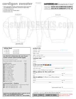


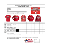

© Copyright 2026