
Light path model of fiber optic liquid level sensor considering
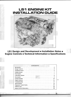
Light path model of fiber optic liquid level sensor considering residual liquid film on the wall Zhijun Zh ang,* Shiwei Zhang School of Mechanical Engineering and Automation, Northeastern University, 110004, Shenyang City, P. R. China * [email protected] Abstract: The worki ng principl e of the refractive-t ype fiber optic liqui d level sensor is analyzed in detail based on the light refraction principl e. The optic path models are devel oped in consi deration of common simpli fi cation and the resi dual liqui d film on the gl ass tube wall. The cal culating formul ae for the model are derived, constraint conditions are obt ained, infl uenci ng factors are discussed, and the scopes and skills of application are analyzed through instance simul ations. The research results are useful in directing the correct usage of the fiber optic liqui d level sensor, especially in special cases, such as those invol ving viscous liqui d in the gl ass tube monitoring. 1. Introducti on Liqui d level monitoring is necessary in the industry and in the sci enti fi c research fi eld [1]. The designs of li qui d level sensors indi cate the preset height of liquid l evels, incl udi ng magnetic [2], vibrant, capacitive [3], microwave [4], ultrasoni c [5], and phot oelectri c [6, 7]. The traditional glass tube liquid level gauge is widely utilized in simpl e structures for cl ear indi cati on and visual observation [8, 9]. When a gl ass tube liqui d level gauge is combined with a fiber optic sensor, a type of fiber optic liquid level sensor is formed. It includes the opti cal emission fiber, optical accept ance fiber, light source, optical modulat or, ampli fi er, and gl ass tube liqui d level gauge [10, 11]. The advant age of t his sensor is that it can achieve genuine non-cont act liquid l evel monitoring. The additional sensor el ements, such as fl oat or fi ber, are not required to set in the liquid [12-16]. The micro size of the optic fiber enhances the accuracy of liquid level monitoring. The transformation of old equipment, which consist only of the glass tube liquid level gauge and which work by relying on the observations of the naked eye, into automati c liquid level monitoring by adding fiber opti c sensors to the outside of the gl ass tube is convenient. The fiber opti c liquid level sensor has the charact eristics of fast response, corrosion Comment [L1]: No.2 resistance, electri cal insul ation, and small volume as well as the ability to easil y compose the remot e monitoring network with the fiber opti c transmission syst em. Coupl ed with the hi gh sensitivity of the elect roni c ampli fier, this sensor possesses outstanding advant ages in terms of anti-el ectromagnetic int erference capability and high sensitivity [17, 18]. As the advant age of fiber optic liqui d level sensor, the study and application is widely. A noncontact fiber optic liquid level sensor based on the phenomenon of reflective concept is present ed [21]. The devi ce consists of fi ber optic transmitter, fiber optic probe, floating refl ector, photodiode detect or, and digit al multimet er. A simple intensity-modulat ed fiber optic sensor is developed that is based on frustrat ed total int ernal reflection effect caused by refractive index change of a medium surrounding an optical fiber [23]. An optical fiber sensor liquid l evel based on light intensity modul ation, and such modulation results from alteration of tot al internal refl ection into partial refl ection at the interface are reported [24]. A liquid-level sensor based on the refractive-i ndex sensitivity of long-period fi ber-optic gratings is proposed and demonstrated. The form of t he transmissi on spectrum of the long-period grating is dependent on the fraction of the length of the long-period grating that is surrounded by the liquid [25]. A fiber-optic level sensor with special micro-opti cal refractometri c transducer designed to measure the level of liquid propane-but ane in a rel atively short range (60 cm) in the top part of storage tanks at oil refi neries [26]. A micro change in level using pl astic optical fi ber sensor is demonstrated [20]. This sensor operat es on light intensity modul ation and such modul ation results due to Comment [L2]: No.3 displ acement of the refl ector fl oati ng on the liqui d. An experimental realization of a simpl e all-fi ber-optic sensor for liquid level measurement is demonstrat ed. It is an int ensit y-modul at ed on-off switching sensor whose operating principl e is based on the frust rat ed-t otal-i nternal -refl ection effect caused by the refractive-index change of the surrounding medium [27]. An intensity-based fiber-optic liqui d-l evel sensor for point measurement is described. The sensing princi ple is based on the total internal refl ection of light, which is disturbed by contact with a liquid [28]. A simple and compact refl ective liquid level sensor based on modes conversion in the thin-core fiber incorporating one tilted fi ber Bragg grating (TFBG) is proposed and experiment ally demonstrated. [30]. A new and simpl e fiber-optic liqui d level sensor based on light intensity modul ation was present ed when rising and falling mode of liquid level causes coupling opti cal pat h distance vari ation bet ween two opti cal fibers [34]. A fi ber-optic liqui d level sensor that is conducted by a combination of optical interferomet er and lever principl e is presented [12]. Its sensing unit is a Mach-Zehnder interferomet er (MZI). The measuring equipment is composed of a rot atabl e lever and a fi xed link. A fiber-opti c liquid l evel sensor based on multimode int erference (MMI) effects is proposed and demonst rat ed [13, 17]. The MMI and sel f-image effect s can be effecti vely applied for multiplexed liquid level sensing, because the natural response as a band-pass filt er for each sensor is clearly distinct from each other, in the case for several sensors working at the same time. A simpl e and low-cost discret e liquid-l evel measurement syst em consists of a group of pl asti c opti cal fi ber segments, whi ch are aligned coaxially and spaced equally is present [29]. A novel optical liquid level sensor based on pol ari zation-mai ntai ning fiber (PMF) modal interferomet er with waist enl arge splici ng is proposed [31]. The design and packagi ng of simpl e, small, and low cost sensor heads, used for continuous liquid level measurement usi ng uni formly thi nned (etched) optical fiber Bragg grating (FBG) are proposed [33]. An asymmet ric Fabry-Perot fiber-optic pressure sensor is capable to precisely measure liquid levels [22]. They are directly proportional to pressures that can modul ate cavit y length of F abry-Perot cavity. An effi ci ent approach to develop large-range liquid level sensors based on an ext rinsi c Fabry-Perot opti cal fiber interferomet er with an all fused-silica structure and CO2 laser heating fusi on bondi ng technol ogy is also present ed [32]. Comment [L3]: No.4 Although t he pri ncipl e of t he refracti ng-type fiber optic liquid level sensor is simple and cl ear, the method and rul es for its appli cation, such as the arrangement of bot h emissi on and accept ance optical fibers, are quit e compl ex. In practi ce, the position and angle of the optical fi bers are determined by dri ftless tests in most cases because of the lack of quantitative theoreti cal basis. However, blind search does not always work, and theoreti cal analysis is necessary in special cases of applications. 2. Problem Description The study in present paper is from the practical probl em encountered when they devel oped the “ automati c vapor vacuum pump performance measurement syst em” patented in China (Chi nese Patent: ZL200910012545.3) [19]. Accordi ng to the performance measuri ng method of vapor vacuum pump whi ch recommended by both the international standard ISO 1607-1 (1993) and the Chinese standard GB/T 19955.1 (2005). The measurement of volume rat e of flow (pumping speed) need to monitor the liqui d level in a seri es of glass tubes with given diameter. In the experiment, the liquid l evel is forced t o rise and drop several times between the two preset hei ghts which is 20 cm. The change of liquid level is because the change of pressure on the top of liquid. The inner di amet ers of the gl ass tubes in present study are 1.5mm, 3mm, and 5 mm accordi ng to above standard. The liquid medi um in the tube is a type of industry transformer oil with lower sat uration vapor pressure in order to limit oil pollution for vapor vacuum pump. The oil is transparent and with higher viscosity. In order to realize the automatic test, the fiber liqui d level sensors are the best met hod as above mentioned. The two fiber opti c liquid level sensors are set and provide the responsive signals. The devi ce phot ograph of fi ber optic liqui d level device is show in fi gure 1. The refracting-type fiber optic liquid level sensor was devel oped based on the princi ple of light refraction. The inci dence detecting light beam ( AB in Figure 2) from the opti cal emission fiber arri ves at the outer surface of the gl ass tube obliquely and passes through the glass tube sinuously. The light beam ( GT HT or GD H D in Figure 2) is then Comment [L4]: No.1 recei ved by the opti cal acceptance fiber, which is located on the ot her side of the gl ass tube at a slant ed angl e. The optical path is a zigzag line across the glass tube because the light beam is refracted at each interface bet ween two transparent medi a with di fferent refractive indi ces. The light path through the liqui d ( ABCFD GD H D in Figure 2) is different from the path through the gas ( ABCFT GT HT in Figure 2) because of the di fference in the refractive indi ces of the liquid and gas inside the glass tube. Therefore, the position and angl e of the emergent det ecting light beam passi ng through the liquid are di fferent from those of the beam passi ng through the gas. If the optical acceptance fiber is arranged at a position and angle correspondi ng to the emergent detecting light beam passi ng through the liquid with the possibility of recei ving the light signal, the emergent det ecti ng light beam passing through the gas will not be received and vi ce versa. Thus, the refracting-t ype fiber opti c liquid level sensor works well when the liquid is good and transparent. 2 1 3 4 5 7 6 Fig. 1 The photograph of fi ber optic liqui d level sensor in present study However, the optical accept ance fi ber cannot frequently receive the emergent light in time at expect ed emergent poi nt ( GT HT in figure 2) because the light pat h is changed to GH as fi gure 2. The change is the residual oil film on the tube wall. It is the medium to change the light pat h. The thickness of oil is changed with the time that duce to GH be changed with the time. The oil film effect is not known well until now. The theory study would be clari fy the det ail information and maybe would guide the appli cation of sensors. In this paper, the light pat h model considering the residual liquid film is established. The deri vation and analysis are performed to meet the requirements for theoretical research provided above. The worki ng mechanism of the refracting-t ype fiber opti c liquid level sensor with gl ass liquid level is discovered. 3. Review of simplified model of optical path The simpli fied model of optical path cal culation [19] is shown with dot line in Fig. 1. It is the cross-section of the gl ass tube. Glass tube cent er O is considered the coordi nate origin, a rectangul ar coordi nat e syst em XOY is established. The darker part is the cylindri cal wall of the glass tube, the out er radius of whi ch is RB and the inner radius of which is RC . At the circle with radius RA , point A is the incident poi nt of the light and point H is the emergent point of the light. Lastly, the ori ginal positioning paramet er of the light path is set. The coordinat e of i ncident poi nt B is select ed as the positioning point of the light path. In the rect angul ar coordinat e syst em XOY, the coordi nate of poi nt B is ( xB RB , yB 0 ). The paramet ers and symbols of the vari ous angl es in Fig. 1 are defi ned as follows: (1) Azimut h: the angl e between the negative X axis of the coordi nate and the normal line at each turni ng point (ABCFGH) in the light path, denot ed by γ with a subscript, such as A , B , and C . (2) Inci dence angl e: the angl e between the incident light and the normal line at each turni ng poi nt (ABCFGH) in the light pat h, denot ed by α with a subscri pt, such as A , B , and C . (3) Refraction angl e: the angl e bet ween the refraction light and the normal line at each turning point (ABCFGH) in the light path, denot ed by with a subscript, such as B . The refraction angl e at poi nt C is especiall y distinguished when the refractive indi ces of the medi a in the tube are di fferent, such as with CT and CD . (4) The total defl ecti on angle: also called total acceptance angl e, this angle is the azimuth di fference bet ween light inci dent point A and emergent point H D or HT . When the opti cally denser medium nD is in the t ube, D is noted as the tot al defl ecti on angl e. When the optically thinner medium nT is in the tube, T is noted as the tot al defl ection angl e. The difference is expressed as the defl ection angl e di fference denot ed by . Fig.2. Light pat h models of three conditions: gas in glass tube ( ABCFT GT HT ), liquid medium in glass tube ( ABCFD GD H D ) and considers residual liquid film on the glass wall ( ABCDEFGH ). Four kinds of opti cal medi a divided by the optical refractive index are invol ved in the glass tube liquid level gauge. Their refractive indices are denot ed by n A , nG , nD , and nT in outward to inward turns. The medium outside the tube that n A stands for is generally air; therefore, nA 1 . However, this relationship is not directl y used to simpli fy the formulae in the followi ng derivation and cal cul ation. nG stands for the refraction index of the glass tube. Two kinds of medi a are present in the tube, and their refraction indices must be different, which is the physi cal basis of the met hod introduced in this article. The medi um with the larger refractive index is called the opti cally denser medium denot ed by nD ; the medium with the less refractive index is called the optically thi nner medium denot ed by nT . Both nD and nT may be less than nG . The optically denser medium is typically a liquid, whereas the optically thi nner medi um is typi cally a gas. The det ecting light emitted from the emissi on fiber goes through this plane. Incident light AB enters the tube at angl e B .The out er surface is normal at point B. When gas is in the tube, the light refracts at points B , C , FT , and GT on the insi de and outsi de surfaces of the tube wall when light passes through the tube. The light is fi nall y recei ved by the opti cal acceptance fiber at point HT . By contrast, the refraction angle of the light changes at point C on the inside of the tube wall when the t ested liquid in the tube reaches the height of the light and when the refractive index changes, resulting in the change in the path followed by the light. The entire light pat h changes to ABCFD GD H D . As point H D defl ects from the origi nal accepting position of point HT , the optical accept ance fi ber at point HT can no longer receive the light signal. Thus, a great contrast with regard to the exist ence of light at the points H D and HT is present before and aft er the increase in the liquid level, thereby improvi ng the responsese sensitivity especi ally in transparent media. 4. Light path model considering residual liquid film on the wall The liquid in the tube is usuall y charact eri zed by high viscosity and large surface tension. The signal response when the liquid surface rises and passes the det ecting light position is unaffect ed. However, a residual layer of liquid film appears on the glass wall when the liquid drops and merely passes the det ecti ng light position. Thus, the incident light must first pass the liqui d film to arrive at the gas area in the tube. The emergent light must also pass through the liqui d film to pass the gl ass wall; therefore, the detecting light must pass through the liquid film twice and refract on the interface. In this period of time, the emergent light angle devi ates from T when only gas is present in the tube as predict ed in the simpli fied model. Over time, the liquid on the wall falls automati cally because of gravity, thereby maki ng the liquid film thinner and the refraction of the det ecting light smaller until the t ube is full of gas and the angle position of t he emergent light returns to T . The probl em of residual liquid film on the wall during the falling process di rectly causes errors in liquid level monit oring. Therefore, special research on this phenomenon is necessary. The light pat h cal culation model consi dering the resi dual liquid film on the wall adopts the basi c assumption and paramet er defi nition of the previous simpli fied model [19]. The graph of the light path model shown with solid line in Fig. 1 was established based on reference [19]. The only change is the addition of a layer of liqui d film in the gl ass tube, whi ch is a circl e concentri c with the inner radius of RD . This addition causes the det ecting light path in the gl ass tube to change from line CFT into three line segments CD , DE and EF in present study in Fig. 2. 4.1. Hypot hesis (1) The out er and inner surfaces of the glass tube are standard coaxial cylindri cal surfaces. The shape error is ignored. (2) All mat eri als involved in the light pat h are isot ropi c homogeneous transparent opti cal media. The det ecti ng light in various medi a is linear, and the light pat h obeys the refraction law at the interfaces of the two kinds of media. (3) The size of t he light can be ignored, i.e., it can be regarded as a geometric strai ght line because it is very fine rel ative to the tube size. (4) When two ki nds of medi a in the tube are convert ed, no residual liquid film exists on the inner surface of the gl ass tube. 4.2. Optical Path Graphi cal Model and Parameters Symbol Definition 4.3. Coordi nate, azimuth and inci dent angl e of poi nt A Point A is the i ntersecting point of t he incident light y kB ( x RB ) with the circl e x 2 y 2 RA2 where the optical emissi on fi ber is located. The slope of the incident light is kB tan B , and the coordi nate of poi nt A is , 1/ 2 2 2 2 x A RB cos B RA RB sin B sin B . 1/ 2 y R sin cos R R 2 sin 2 A B B B A B B The azimuth of poi nt A can be expressed by the slope of line y f A x as, (1) tan A f A yA xA . cos B 1/ 2 sin B cos B RA RB sin B 2 2 1/ 2 2 sin B RA RB sin 2 B (2) 2 At point A, the incidence angl e A is, tan A kB f A 1 kB f A sin B . (3) 1/ 2 RA RB sin 2 B 2 4.4. Refraction angl e of poi nt B At the int erface of point B, nA sin B nG sin B according to the refracti on l aw. The refraction angle of point B can thus be obtai ned as follows: sin B nA sin B . nG (4) or, tan B nA nG sin B 1/ 2 1 nA nG 2 sin 2 B . (5) 4.5. Coordi nate, azimuth, and inci dent angle of point C Point C is the intersecting point of the refracted light from point B y kC ( x RB ) with the circl e x 2 y 2 RC2 on the inner wall of the glass tube. The slope of the refracted light is kC tan B , and the coordinat e of point C is , 1/ 2 2 2 2 xC RB cos B RC RB sin B sin B . 1/ 2 y R sin cos R R 2 sin 2 B B B B C B C (6) The azimuth of poi nt C can be expressed by the slope of line y fC x as tan C f C yC xC . 1/ 2 2 sin B nG nA sin 2 B 1/ 2 nG nA sin B 2 2 1/ 2 2 RC nG RB nA sin 2 B 1/ 2 RC nG RB nA sin B At point C, the incidence angl e C is 2 2 sin B 2 (7) tan C kC fC 1 kC fC sin B . (8) 1/ 2 RC nG RB nA sin 2 B 2 or, sin C RB nA sin B . RC nG (9) 4.6. Refraction angl e of poi nt C The two kinds of medi a with di fferent refractive indices in the tube correspond to two di fferent refraction angles at point C; therefore, the light pat h aft er point C also has two possi ble pat hs. When the refractive index of t he medium in the tube is nT , nG sin C nT sin CT according to the refraction law and Equation (8). The cal culation formul a of the refraction angl e at point C is, sin CT RB nA sin B . RC nT (10) or, tan CT sin B 1/ 2 RC nT RB nA 2 sin 2 B When the refractive index of the medi um in the tube becomes . (11) nD , the refraction angl e at point C as cal culat ed by the refraction law and Equation (8) is, sin CD RB nA sin B . RC nD (12) or, tan CD sin B 1/ 2 RC nD RB nA 2 sin 2 B . (13) 4.7. Coordi nate, azimuth, incident, and refracti on angles of point D Point D is the intersecti ng point of refraction line y kD ( x xC ) yC from point C and inner surface ci rcle x2 y 2 RD 2 of the liquid film. The slope of the refraction line is kD tan(CD C ) , the radius of the circle is RD R C , and the thickness of the liquid film is . The coordi nate of poi nt D in the XOY coordinat es can be obt ained by simpli fication. x sin( ) sin R cos( ) R 2 sin 2 R 2 1/ 2 CD C CD C CD C CD C D D 1/ 2 yD cos( CD C ) sin CD RC sin( CD C ) RD2 sin 2 CD RC2 The same applies to the relationship as follows, yD kD xD yC kD xC . Azimut h D of point D is expressed by the slope of line y f D x as, (14) (15) tan D f D yD xD . (16) 1/ 2 sin CD tan( CD C ) ( RD / RC ) 2 sin 2 CD 1/ 2 tan( CD C ) sin CD ( RD / RC ) 2 sin 2 CD The inci dence angle D of point D is det ermined by the following equation: tan D kD f D 1 kD f D k D xD y D xD k D y D . (17) . (18) This angl e can be obt ained by simpli fication as follows: sin D RC sin CD RD RB nA sin B RD nD The refraction angle D of poi nt D can be obtai ned by the refraction law nD sin D nT sin D . sin D nD sianin D nT RB nA sin B RD nT . (19) or, tan D sin B RD nT / RB nA 2 sin 2 B . (20) 4.8. Total deflection angl e As shown in Fig. 1, the total defl ection angl e from incident poi nt A to emergent point H with the resi dual liquid film is (21) 2(D D A ) . The following have already been calcul ated at this poi nt. D arctan sin B 1/ 2 RD nT RB nA 2 sin 2 B . (22) 1/ 2 D arctan sin CD tan( CD C ) ( RD / RC ) 2 sin 2 CD 1/ 2 tan( CD C ) sin CD ( RD / RC ) 2 sin 2 CD A arctan 1/ 2 cos B 1/ 2 sin B 2 sin B RA RB sin 2 B 2 cos B RA RB sin 2 B . . (23) (24) 2 4.9. Constrai nts of the model When a resi dual liquid film exists on the wall, the constraints must be considered to avoi d the total refl ection of light as in the simpli fi ed model. In this situati on, the total refl ection of li ght is likel y to occur at point D; therefore, the condition of avoiding the total refl ecti on is nT . nD (25) RD nT . RB nA (26) sin D or, sin B 5. Results and Discussion Fig. 3 shows the calcul ated results of total defl ecti on angle D for transformer oil, total defl ection angle T for the vacuum without a residual oil film, and total deflection angl e i for the vacuum with resi dual oil films of di fferent thickness ( 1 for 0.05 mm, 2 for 0.1 mm, and 3 for 0.15 mm). The denser light medi um in the tube is a type of industry transformer oil with nD 1.46 , whereas the thi nner light medium in the tube is a vacuum with nT 1 . The other struct ure paramet ers are RA 12mm , RB 6mm , and RC 1.5mm . The difference bet ween T and i ηD,ηT,η1,η2,η3/degree shows the effect of the residual oil film and expl ains the missing emergent light at point HT. 180 160 ηD ηT η1 η2 η3 140 120 100 80 0 5 Fig. 3. Variation in 10 15 αB/degree 20 25 D , T , and i with incident angle B for example 5.1. Influence of Liquid Film Thickness Total defl ection angle with the resi dual liqui d film on the wall, which is calcul ated with Equation (21), is always less than total defl ection angle T without the resi dual liqui d film calcul ated with Equation in reference [19]. As shown in Fig. 3, the thicker the film, the great er the di fference bet ween T and . Thus, defl ection angl e di fference D bet ween optical thi ckness and the thi nner medi a is large. When the thickness of t he residual liquid film decreases, the light at emergent poi nt H is near point HT , and is close to T . 5.2. Influence of the Incident Angl e As shown in Fig. 3, the larger initial detecting light incident angle B of det ecting light is, the great er the di fference between H and HT is under the condition of similar liquid film thickness; this phenomenon is accompanied by the increase in gas–liqui d medi a defl ection angle di fference D . A critical incidence angl e BK arcsin(( RD nT ) / ( RB nA )) is determi ned with Equation (26) for each speci fi ed film thi ckness. The determined critical incidence angl e is always small er than critical incidence angle BT max arcsin(( RC nT ) / ( RB nA )) that does not consi der the resi dual liquid film. When act ual incidence angle B BK , actual total defl ection angl e can be calcul ated with Equati on (21). When BK B BT max , the total detecting light refl ection occurs on the liquid film interface, and the emergent light is not emitted at gas emergent point HT until the liquid film disappears. 5.3. Critical incidence angle at point B The analysis above provi des a very import ant conclusi on: in the presence of resi dual liqui d film on the tube wall, the recei pt of the emergent light at emergent point HT is unreli abl e as mentioned in the simpli fied model. The best substitution met hod in this situation is to select H D as the light emergent point, whi ch corresponds to the liquid in the glass tube. Total defl ection angl e can be calculat ed with Equation (21). Thus, the effect of t he residual liquid film on emergent points H and HT need not be considered even with regard to the possibility of t he occurrence of tot al refl ection when gas is in the tube. The only requi rement is to ensure that the liqui d in tube is transparent and that total refl ection does not occur when the det ecting light passes through the liquid. Therefore, the maxi mum allowabl e inci dent angl e (critical incidence angle) at poi nt B is BD max arcsin( nD RC ). nA RB (27) 6. Conclusions The opti cal fi ber liquid level sensor composed of a gl ass tube level gauge and a fiber opti c sensor can monitor transparent liquid level in a thin gl ass tube through the method based on the light refraction principl e. The accept ance fi ber should be set at the emergent point of t he optically denser medi um in the tube when the infl uence of the resi dual liquid film on the tube wall cannot be ignored to receive the emergent light signal. The total refl ection of t he detecting light in the optically thinner medium can generally be adopt ed by i ncreasing the inci dent angle t o within t he constraint condition of the opti cally denser medi um. Conflict of Interests The authors decl are that there is no confli ct of interests regardi ng the publication of this paper. Acknowledgments This research was supported by National Nat ural Science Foundation of C hina (Grant Nos. 31000665, 51176027, 31371873 and 31300408) and the Fundamental Research Funds for the Central Universities of C hina (Grant No. N130403001). References and links 1. T. A. Hughes, Measurement and control base (Instrumentation system, 2002). 2. I. Velt, and Y. Mikhailova, "An electromagnetic method of measurement of the flow rate and level of a liquid in free-flow pipelines," Measurement Techniques 56, 797-804 (2013). 3. K. Matsumoto, M. Sobue, K. Asamoto, Y. Nishimura, S. Abe, and T. Numazawa, "Capacitive level meter for liquid hydrogen," Cryogenics 51, 114-115 (2011). 4. J. Liu, X. Z. Chen, and Z. Zhang, "A novel algorithm in the FMCW microwave liquid level measuring system," Measurement Science & Technology 17, 135-138 (2006). 5. V. E. Sakharov, S. A. Kuznetsov, B. D. Zaitsev, I. E. Kuznetsova, and S. G. Joshi, "Liquid level sensor using ultrasonic Lamb waves," Ultrasonics 41, 319-322 (2003). 6. E. Musayev, and S. E. Karlik, "A novel liquid level detection method and its implementation," Sensors and Actuators a-Physical 109, 21-24 (2003). 7. S. Khaliq, S. W. James, and R. P. Tatam, "Fiber-optic liquid-level sensor using a long-period grating," Optics Letters 26, 1224-1226 (2001). 8. S. C. Bera, J. K. Ray, and S. Chattopadhyay, "A low-cost noncontact capacitance-type level transducer for a conducting liquid," Ieee Transactions on Instrumentation and Measurement 55, 778-786 (2006). 9. N. B. Manik, S. C. Mukherjee, and A. N. Basu, "Studies on the propagation of light from a light-emitting diode through a glass tube and development of an optosensor for the continuous detection of liquid level," Optical Engineering 40, 2830-2836 (2001). 10. B. Xu, J. Q. Li, Y. Li, and X. Y. Dong, "A Thin-Core Fiber Modal Interferometer for Liquid-Level Sensing," Chinese Physics Letters 29, (2012). 11. C. L. Lee, Y. C. Zheng, C. L. Ma, H. J. Chang, and C. F. Lee, "Dynamic micro-air-bubble drifted in a liquid core fiber Fabry-Perot interferometer for directional fiber-optic level meter," Applied Physics Letters 102, 12. Interferometry," Ieee Photonics Journal 6, 13. (2013). X. P. Zhang, W. Peng, Z. G. Liu, and Z. F. Gong, "Fiber Optic Liquid Level Sensor Based on Integration of Lever Principle and Optical (2014). J. E. Antonio-Lope z, D. A. May-Arrioja, and P. LiKamWa, "Fiber-Optic Liquid Level Sensor," Ieee Photonics Technology Letters 23, 1826-1828 (2011). 14. F. Perez-Ocon, A. Rubino, J. M. Abril, P. Casanova, and J. A. Martinez, "Fiber-optic liquid-level continuous gauge," Sensors and Actuators a-Physical 125, 124-132 (2006). 15. P. Raatikainen, I. Kassamakov, R. Kakanakov, and M. Luukkala, "Fiber-optic liquid-level sensor," Sensors and Actuators a-Physical 58, 93-97 (1997). 16. K. R. Sohn, and J. H. Shim, "Liquid-level monitoring sensor systems using fiber Bragg grating embedded in cantilever," Sensors and Actuators a-Physical 152, 248-251 (2009). 17. J. E. Antonio-Lope z, J. J. Sanchez-Mondragon, P. LiKamWa, and D. A. May-Arrioja, "Fiber-optic sensor for liquid level measurement," Optics Letters 36, 3425-3427 (2011). 18. S. M. Chandani, and N. A. F. Jaeger, "Optical fiber-based liquid level sensor," Optical Engineering 46, 19. Wensheng Liang. Shiwei Zhang, Guozhao Ji, "A novel fiber- optic liquid level sensor with adjustable light path based on principle of light (2007). refraction," Applied Mechanics and Materials 6, 573-578 (2010) 20. SENGUPTA, D., SHANKAR, M. S., REDDY, P. S., PRASAD, R. L. N. S., NARAYANA, K. S. & KISHORE, P. (2011). Micro-change in liquid level sensing by extrinsic fiber optic sensor. Optoelectronics and Advanced Materials-Rapid Communications, 5, 491-494. 21. BINU, S., KOCHUNARAYANAN, K., PILLAI, V. P. M. & CHANDRASEKARAN, N. (2010). Pmma (Polymethyl Methacrylate) Fiber Optic Probe as a Noncontact Liquid Level Sensor. Microwave and Optical Technology Letters, 52, 2114-2118. 22. LU, T., LI, Z. J., XIA, D. Q., HE, K. H. & ZHANG, G. Y. (2009). Asymmetric Fabry-Perot fiber-optic pressure sensor for liquid-level measurement. Review of Scientific Instruments, 80. 23. NATH, P., DATTA, P. & SARMA, K. C. (2008). All fiber-optic sensor for liquid level measurement. Microwave and Optical Technology Letters, 50, 1982-1984. 24. GOLNABI, H. (2004). Design and operation of a fiber optic sensor for liquid level detection. Optics and Lasers in Engineering, 41, 801-812. 25. KHALIQ, S., JAMES, S. W. & TATAM, R. P. (2001). Fiber-optic liquid-level sensor using a long-period grating. Optics Letters, 26, 1224-1226. 26. SVIRID, V. A., DE LEON, V. & KHOTIAINTSEV, S. N. (2000). A prototype fiber-optic discrete level-sensor for liquid propane-butane. Ieice Transactions on Electronics, E83c, 303-308. 27. ILEV, I. K. & WAYNANT, R. W. (1999). All-fiber-optic sensor for liquid level measurement. Review of Scientific Instruments, 70, 2551-2554. 28. RAATIKAINEN, P., KASSAMAKOV, I., KAKANAKOV, R. & LUUKKALA, M. (1997). Fiber-optic liquid-level sensor. Sensors and Actuators a-Physical, 58, 93-97. 29. LIN, X., REN, L. Y., XU, Y. P., CHEN, N. N., JU, H. J., LIANG, J., HE, Z. Q., QU, E. S., HU, B. W. & LI, Y. L. (2014). Low-Cost Multipoint Liquid- Level Sensor With Plastic Optical Fiber. Ieee Photonics Technology Letters, 26, 1613-1616. 30. GU, B. B., QI, W. L., ZHOU, Y. Y., WU, Z. F., SHUM, P. P. & LUAN, F. (2014). Reflective liquid level sensor based on modes conversion in thin-core fiber incorporating titled fiber Bragg grating. Optics Express, 22, 11834-11839. 31. GONG, H. P., SONG, H. F., ZHANG, S. L., NI, K. & DONG, X. Y. (2014). An optical liquid level sensor based on polarization-maintaining fiber modal interferometer. Sensors and Actuators a-Physical, 205, 204-207. 32. WANG, W. H. & LI, F. (2014). Large-range liquid level sensor based on an optical fibre extrinsic Fabry-Perot interferometer. Optics and Lasers in Engineering, 52, 201-205. 33. SENGUPTA, D. & KISHORE, P. (2014). Continuous liquid level monitoring sensor system using fiber Bragg grating. Optical Engineering, 53.


© Copyright 2026