
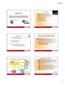
TDS - EMC LIVE 2015
5/1/2015 Agenda • Introduction/Overview Improve EMC Compliance and Precompliance Testing Throughput with Time Domain Scanning – What Is Time Domain Scanning – Benefits of Time Domain Scanning • Commercial S • MIL STD • Issues/Concerns Mark Terrien Keysight Technologies EMC Business Manager – Using appropriate Dwell Time – Complying with CISPR standards – Preselector design Factors Affecting EMC Test Times Reduced EMC Test Time Improves Revenue and Time-to-Market Many factors affect both Compliance and Precompliance test times Compliance testing ‒ Chamber time is a limited resource ‒ Reducing test time improves efficiency and profitability •Device Under Test (DUT) setup time •Receiver/ Spectrum Analyzer scan times •Turntable and antenna movement times Precompliance testing •Suspect frequency analysis ‒ Rapid diagnosis of early designs speeds time-to market, facilitating product sales •Final measurement Benefits Test Facilities and Manufacturers Key Benefit: Reduced Test Time! Time Domain Scan (TDS) • Collect list of suspect frequencies faster • What is “Time Domain Scan” - Device Under Test A new way to do Frequency scanning Swept scans, Stepped scans, now Time Domain scans DUT Emissions • FFT-based FFT based scan - • uses ~ 90% overlap (in time) to ensure amplitude accuracy for measurements of both CW and Impulsive signals Allowed by CISPR 16, but not required. • Benefits CISPR/FCC testing the most - Internal Automotive industry testing specifications require Time Domain ‒ Commercial testing requires turntable and antenna optimization = more required scanning 6 5 1 5/1/2015 Classic Super Heterodyne Architecture How Time Domain Sweep Saves Time Only have to dwell for each FFT BW (multiple RBWs) Have to dwell at each RBW Reference Oscillator Step/Sweep Generator Synthesizer Receiver FFT BW (Acquisition BW) Receiver Resolution BW amplitu ude RF Section amplitu ude Video Display Analog IF Local Oscillator RBW Filter IF Gain Log Amp Detector Video Filter Log Input ADC DownRF Input Pre-selector conversion Attenuator 5 or 10 dB Steps Resolution BWs Swept or Stepped Frequency Scan IF Gain Stages Logarithmic Amps Detector Variable bandwidth Selectable linear filters used for gains used to set analysis reference levels frequency frequency Time Domain Frequency Scan Provide display dynamic range 8 7 Review: CISPR Radiated Measurement Methodology All-Digital IF Architecture Facilitates TDS Digital Conversion at IF instead of Video ADC • Wider IF Bandwidths • Powerful microprocessors 1. Fast Prescan to collect all suspect emissions DSP Log Amplification RBW Filtering Detection Video Filtering Averaging Display Scaling Signal Digitized After RF DownConversion 2. Identify all emissions above target limit line • Advanced DSP techniques Downconversion IF IF Filter Gain 3. Perform final measurement on individual signals Video Filter Log Amp Log i. ADC Find peak of signal, then make final measurement using appropriate CISPR detector: Quasi-Peak, EMI-Avg, RMS-Avg Pre-selector Local Oscillator RF Input Attenuator Reference Oscillator TDS i. Scan speed limited by CISPR Helps Here ii. Speed limit ensures you capture all emissions iii. Typically use Peak detector, but can use CISPR detector DUT Emissions Device Under Test Step/Sweep Generator Video Display 9 9 10 Test Time Reduction Example: CISPR*-based Test 1 to 4 m above ground plane Long Dwell Time Plus Many Scans = Lots of Time Test in vertical and horizontal position DUT 360 deg Test in vertical and horizontal position 1 to 4 m above ground plane DUT 360 deg 3, 5 or 10 m F Frequency Domain D i Scan S 1. rotate DUT through 360°, scanning every 15° = 24 scans 2. test at 3 antenna heights (from 1– 4 meters) 3. both vertical and horizontal orientation Purpose: identify peak emissions 3 or 10 m CISPR Band x3 30MHz–1GHz x2 144 scans Peak det. 10ms. dwell RBW =120kHz 3 pts/RBW ~ 250 sec 150kHz–30 MHz Peak det 100ms. dwell RBW = 9kHz 2 pts/RBW collect a list of suspect emissions for final measurement * Example based on methodology defined in CISPR 16-2-3: Edition 3.1 section 7.6.6 144 scans Typical Industry Swept or Stepped times 660 - 750 sec x 250 sec/scan 10 hours Not counting antenna and turntable positioning time Keysight Confidential 11 12 2 5/1/2015 Time Domain Reduces Scan Time Time Domain Scan Offers Significant Pre-scan Time Reduction 1 to 4 m Test in vertical and horizontal position above ground plane CISPR Band Time Domain Scan Frequency Domain Scan Typical Industry TDS times Typical Industry Scan times ~ .5 to 13 seconds ~ 250 seconds MXE EMI Receiver DUT 360 deg 3 or 10 m 30MHz–1GHz Peakk det. P d t 10ms. 10 d ll dwell RBW =120kHz 3 pts/RBW Ti Time Domain D i Scan S CISPR Band 30MHz–1GHz 150kHz–30 MHz Peak det 100ms. dwell RBW = 9kHz 2 pts/RBW 144 scans 2 x ~250 sec/scan Typical Industry TDS Time ~ .1 to 11 seconds Peak det. 10ms. dwell RBW =120kHz 4pts/RBW 660 - 760 seconds ~ .5 to 13 seconds 10 hours 150kHz–30 MHz Peak det 100ms. dwell RBW = 9kHz 4 pts/RBW 13 4.8 minutes ~ .1 to 11 seconds Not counting antenna and turntable positioning time 14 TDS Benefit for Testing Short Operation-Time Devices Time Domain Scan and MIL STD 461 Example: Automotive Starter motors • Operating for extended periods during testing leads to overheating / thermal damage • Time domain scanning significantly reduces test time. Test in vertical and horizontal position No antenna height variation No device rotation DUT 1m • MIL STD requires fewer scans: - no turntable rotation - no antenna motion • MIL STD specifies dwell times - 15ms/point for Freq > 1 kHz • MIL STD 461F: no specific mention of TDS • MIL STD 461G: proposed draft allows TDS Time Domain Scan and MIL STD 461 Agenda From recent draft of MIL STD 461G: • Introduction/Overview – What Is Time Domain Scanning – Benefits of Time Domain Scanning • Commercial S • MIL STD • Issues/Concerns – Using appropriate Dwell Time – Complying with CISPR standards – Preselector design 3 5/1/2015 Compliance with CISPR TDS Dwell Time Must be Equal to or Greater than the Emission Pulse Period Correct Dwell Time TDS Dwell Time = 20ms Time Domain accepted as of CISPR 16-1-1:2010 1. Usable for pre-scan to create suspect list? Emission 2usec RF pulse Yes – this is the key contribution time e 2. Usable for Final measurement? Pulse Period 20ms TDS Dwell Time = 10ms TDS samples w/o pulse, signal not displayed Incorrect Dwell Time Only if standard specifically references CISPR 16-1-1:2010 - currently, only CISPR 13 and CISPR 32 - other CISPR documents being adapted Emission 2usec RF pulse time Pulse Period 20ms Compliance with CISPR (cont.) 2. Usable for Final measurement? b) methodology must comply with recommended measurement methodologies CISPR 16-2-3: 2010 RF Preselector Design Considerations Issue: TDS Speed vs Susceptibility to Overload TDS speed is a function of: - width of IF acquisition bandwidth - processing speed - must monitor each suspect to ensure QP value is constant - if QP not constant, must monitor for 15 seconds needs - if QP varies by y more than +/- 2dB in 15 seconds,, signal g to be monitored for a longer period. Single TDS sweep does not meet CISPR requirements for Final Measurement Preselection – What is it, Why use it? Simplified Simplified Low band Path (≤ 3.6 GHz in X-series) Input RFLow Preselector pass (bandpass filter filters) Low band Down-conversion Spectrum EMI Analyzer Receiver Front FrontEnd End RF Input Attenuator (Keysight, R&S, etc.) High band Path YIG preselector filter (microwave bands) ~ 60 MHz 3dB BW Microwave band Down-conversion RF Preselector Acquisition bandwidth limited by RF Preselection bandwidth Wider Preselector Filters Enable Faster Scanning Speed Preselector Input • Provides Dynamic Range to measure CISPR pulse / meet CISPR 16 requirements Display freq Wider Preselector Filters enable… Narrow Preselector Filters Acq. BW freq. – critical piece of a CISPR-compliant EMI receiver – reduces broadband energy to 1st Mixer – measure with less input attenuation Acquisition BW A/D Micro Processor • Bank of Filters before first mixer (fixed or tuned) • Helpful when measuring large impulses (which have wideband spectral energy) DownConvert Wide Preselector Filter • Use of Wider Acquisition BWs • Fewer Acquisitions for a given frequency range • Faster Scanning ..BUT there is a Problem…. Acquisition BW freq . 4 5/1/2015 Compare Two Receivers: Wider Filters Overload First Wider Preselector Filters = Reduced Impulse Overload Protection Receiver 1: Wide Preselector Filters Receiver RF Section Input pulse Vp Wide BW Input pulse Vmax = Vp Τ BWi Impulse BW BW i Vp RF Input Attenuator Vp1 Overloads Receiver 1 Vp1 RF Preselector Downconversion Receiver 2: Narrow Preselector Filters RF Input p Attenuator Τ= pulse width Τ= pulse Downconversion RF Preselector Narrow BW width Max Mixer input voltage is proportional to Preselector Filter Bandwidth RF Input Attenuator Receiver with Wider Preselector filters will Overload earlier for same pulse 25 RF Preselector Vp2 Downconversion Vp2 < Vp1 Vp2 does not overload Receiver 2 Wider Preselector filters can result in lower impulse dynamic range 26 Compare Two Receivers: Wider Filters Require More Input Attenuation to Eliminate Overload Receiver 1: Wide Preselector Filters Input pulse Vp Att1 RF Input Attenuator Wide BW Rx 1 requires larger Att1 to eliminate overload! Vp1 Downconversion RF Preselector Receiver 2: Narrow Preselector Filters Τ= pulse width Att2 Narrow BW RF Input Attenuator Vp2 RF Preselector Att1> Att2 Rx1 sensitivity now worse than Rx2 Downconversion Wider Preselector filters can result in worse sensitivity Summary ‒ Time Domain significantly reduces test time • CISPR • Accepted by CISPR for use in receivers • Greatest value is in Prescan • MIL STD 461F • Not specifically called out in 461F • Allowed in 461G ‒ Critical to use appropriate dwell time • Dwell time must be at least 1/ (DUT Pulse repetition rate) • Needed to ensure emission during Dwell period ‒ Be aware of lower overload thresholds when using receivers with wide preselector filters 27 N9038A MXE EMI Receiver Provides World-Class EMI Measurement Capability • Commercial and Military Compliance - CISPR 16-1-1: 2010, MIL-STD-461F - all required detectors, bandwidths With Optional Time Domain Scan Keysight X-Series Signal Analyzers + N6141 EMC Application: Powerful Precompliance Tools PXA N9030A • Broad Frequency Coverage - 20 Hz to 3.6, 8.4, 26.5 and 44 GHz - tunable to <10 Hz With Optional Time Domain Scan N6141 A EMI Application MXA N9020A • Excellent accuracy - 0.5 dB @ 1 GHz • Excellent sensitivity EXA N9010A • Broad Range of Price + Performance Levels - DANL = -166 dBm @ 1 GHz w/ NFE - Built-in standard preamplifier • Powerful Diagnostic Tools CXA N9000A • Common User Interface with MXE 5 5/1/2015 Questions? Thank you for your attention! Thanks for attending! Don’t miss our Test Bootcamp! November 12, 2015 www.emclive2015.com 6


© Copyright 2026