
axisymmetric buckling of bimodulus thick circular plates
0045-7949.87
13.00 + 0.00
Ltd.
Pergamon
Journals
AXISYMMETRIC BUCKLING OF BIMODULUS
THICK CIRCULAR PLATES
DAR-PING JuANGt and LIESWEN CHEN~
Department of Mechanical Engineering, National Cheng Kung University, Tainan, Taiwan 700,
Republic of China
(Receiced 13 January 1986)
Abstract-The static buckling of bimodulus thick circular and annular plates subjected to a combination
of a pure bending stress and compressive stress is investigated. The thick finite element model, which
includes the effect of transverse shear deformation, are created for axisymmetric buckling problems. The
obtained results of buckling coefficient are compared with the exact solutions for ordinary thin plates.
The accuracy of the finite element solutions are shown to be very good. The etTects of various parameters
on the buckling coefficients and neutral surfce locations are studied. The bimodulus properties are shown
to have significant influences on the buckling coefficient.
NOTATION
A
B
:
Q,
E’, E’
v’, vc
G’, G’
G”
G’*
s
No,
MO,Ma*
N,
K”
internal radius
external radius; radius for cirular plate
plate thickness
stretching stiffness matrix
bending-stretchng
coupling stiffness
matrix
bending stiffness matrix
material elastic matrix
plane-stress
reduced
stiffness
coefficients
respective tensile and compressive and
Young’s moduli
respective tensile and compressive
Poisson’s ratios
respective tensile and compressive
shear moduli
respective tensile and compresive
transverse shear moduli
transverse
istropic
parameter,
S = G’+/G’ = G’*/G’
initial stress and moment results
buckling load, N, = hP,
buckling coefficients,
NJ:
neutral surface position, L,, = 0 and
c@j= 0
ratio
stress,
initial
initial
of bending stress to normal
/I = P,/P.
external normal stress
external bending stress
INTRODUCTION
Recent investigations
concerning composite materials
have shown some composites to behave differently
under simple tension and compression [ 11.In addition
to composite materials, some polycrystalline graphites and high polymers also behave differenw in
tension and compression [2]. This characteristic bet Graduate student.
SProfessor.
C.A.S. 2112-B
havior, although
actually cumilinear,
is often
approximated by two straight lines with a slope
discontinuity at the origin. Thus they are called
bimodulus materials (see Fig. 1).
It is believed that the first modem development of
the basic constitutive equations of bimodulus materials was proposed by Ambartsumyan [3]. Bert [4] used
the macroscopic material model [j] to study the laminated bimodulus composite plates. The bending
analyses of bimodulus laminated rectangular plates
are studied by Bert and his associates [6-S]. Bert et
al. [9] are the first to study the vibration of thick
rectangular bimodulus composite plates. Kamiya [lo]
treated large deflections of a circular plate by finite
difference, and he also applied the energy method to
large deflections of a rectangular plate [I 11. Doong
and Chen [12] investigated the axisymmetric initially
stressed vibration of circular plate by using Galerkin
method on the basis of Brunelle and Robertson [13].
The buckling problems appearing in the literature
are sparse. Jones investigated the buckling of circular cylindrical shells [14] and stiffened multilayered
circular cylindrical
shells [15] on the basis of
Ambartsumyan [3]. Doong and Chen [24] studied the
buckling of thick bimodulus rectangular plates. No
publication is to be found on the buckling of bimodulus circular and annular plates under a combination of bending stress and compressive stress.
In the present work, we employ the energy method
to obtain the elastic and geometric stiffness matrix as
indicated by Przemieniecki [ 161.For the finite element
model, the annular ring elements will be used and the
Lagrangian
polynomials
other than Hermitian
ones [17-191 are used to complete this work. The
buckling coefficients for ordinary material (not bimodulus) circular plate obtained by present works
are compared with the exact solutions [20]. The
influence of various parameters on the neutral surface
locations and the buckling coefficients of bimodulus
plates are investigated.
DAR-PISG JUANGand LIEN-WEIVC&K
116
which can also be expressed as
e=i+e’,
(3)
where 0 denotes the linear strains while e’ denotes the
nonlinear strains.
For the Mindlin plate theory, the displacements are
assumed to be the following form
<,(r, 42) = u(r, 0) + zti/*fr, 8)
C%r, 0, z) = r(r. 6) + z$o(r, B)
S:(r, 0, z) = +o(r, e),
Fig. I. Stress-strain relation of linearized different modulus
material.
STRAIN
ENERGY
The finite element stiffness matrices used in the
displacement method of stability analysis can be
derived most conveniently by starting with the nonlinear strain-displacement
equations. Following a
technique
described
in [21,22],
the nonlinear
strain~isplacement
equations, i.e. Green’s strain tensor, in the cylindrical polar coordinate for the thick
plate problems are as follows:
(4
where u and c are in-plane displacements and w is the
lateral deflection of the neutral surface, while II/, and
r/f0account for the effect of transverse shear.
The total potential energy of an elastic body is
given as
n = U - jjje,sdV
”
- jjT1’)u,dS,
(5)
J
where U is the strain energy, B, is the body force and
v) is the surface traction. In the present problem the
body force and surface traction are considered to be
zero.
Let ci* be the initial stress matrix and written as
Substituting equations (4) and (1) into equation (5)
and neglecting higher order terms, the total potential
energy due to the initial stresses is found to be
jr=- ;
[ur(E’+ zFr)Q(E f zF)u
jD
+ 2: ur(G;-t
:.-I
zH;)a’(G,+
zHj)uldK
(7)
where Q represents the reduced material elastic ma-
The above strains can be denoted collectively by a
-.
column matrix
er= (e,e88e~e,ze0z)
(2)
trix of transversly isotropic elastic material. The
detail of the matrices E, F, G, and H, can be seen in
the appendix, and the displacement vector u is expressed as
Axisymmetric buckling of bimodulus thick circular plates
177
Jh.?
MO*
=J i-2&o&
(1%
h,Z
THE RITZ FINITE ELEMENT
MO
za’dzb dz
=
-h,?
For the finite element methods, the displacements
can be expressed by the equation
-h’?
(9)
where the subscript ‘&e”denotes that the variables are
defined on the element, a@are the shape functions and
ur is the nodal displacements to be determined.
Substituting
equations (9) and (7) and subsequently applying the principle of minimum potential energy, we have
$=Ki=O,
where K represents
written as
(10)
the stiffness matrix. K can be
K=K,+K,,
(II)
where
K, =
It is noted that all the denotations E, E, Gj and fii
and fii represent the product of the one without hat
“ - 9,
and shape functions ai,, and li is the finite
element nodal displacements. It has therefore been
demonstrated that both the elastic and geometrical
stiffness matrices can be determined from integrals of
simple matrix products evaluated over the area. For
bimodulus materials, the different properties in tension and compression cause a shift in the neutral
surface away from the geometric midplane and thus
symmetry about the midplane no longer holds. The
result of this is that bending-stretching
coupling,
similar to orthotropic behavior, is exhibited. Thus,
once the neutral surface has been determined, the A,
B and D are given in the next section. When the
combined stiffness K has been determined, the equations of the present problem are then formulated as
(E’ + zP*)Q(E + z@)dV
IY
=
@‘Ai? + erBE
(KE + K,)ti = 0,
(16)
where ti is the finite element nodal displacements;
these are homogeneous simultaneous equations.
+ i?BP)
Now, we put
+ #‘D@jdA
(12)
represents the elastic stiffness, and A, B and D are
flexural-extensional
coupling
and
extensional,
flexural stiffness matrices, respectively, and they are:
K, =IK&
where L is called the load factor and KZ:is the relative
reference of geometric stiffness due to intense initial
stresses. Then, for nontrivial solutions of equation
(16), the following relation must hold.
lK,+LK;l
D=
z2QVdz,
(13)
in which the material elastic constants Q, are in the
appendix, and while
K,=
i
~(G;Z+zfi:)d”(G,+
5Y
=
+ I-iiTl@G,)
ziti)dP
+ Ei,%“*fii]
dA
(14)
represents the geometric stiffness matrix. The matrices Ho, h;r” and I@* are defined by
--
J
(17)
=O.
(18)
This equation represents the stability determinant.
The smallest value of L determines the instability
condition for a specified loading configuration. The
eigenvalue problems can be solved by means of any
of the standard eigenvalue computer programs.
THE RING ELEIMENT MODEL
The present paper will employ the finite strip to
demonstrate the axisymmetric buckling problem. The
advantages of finite strip are indicated in [23]; they
include fewer data input, smaller matrix dimensions
and more accurate solutions, etc. Thus the present
problem will be simplified to a one-dimensional problem when we use ring elements to complete it.
In the present work, it is clear that u = 0, J10= 0
and Z/a0 = 0 in E, F, Gi and H, for axisymmetric
problems, and the Lagrangian polynomials will be
used as shape functions, i.e.
hi2
No=
-h/2
;‘dz
u~=Caj*ljj,
i
(19)
178
DAR-PISG JUASG and LIEN-WEN CHEN
Z,, one sets
e,, = n., + Z” IL,, = 0,
(22)
which can be displayed at Gauss points. An iterative
procedure is used to obtain the final displacement
ratios. Thus we can give the A, B and D as [8,9]
h?
A/=
Q,dr
j -h, 2
(Qel+Q/j,>(hP)
=
(Q,z
-Q,,%
+
B,= h2 =Q&
s-h:
=(Qi,,
- Q,dh%)
(Q,,?
- Q,,,(Zi/2)
+
fh.?
D, =
Wb\/
z'Q& = (Q,+ Qi,2)@'/24)
J
-h,?
Wa
+
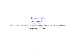
Nodal circles
Fig.
2. Annular
ring
plate element
displacements.
and
its
generalized
where superscript “e” denotes element, the asterisk
denotes element-by-element
matrix multiplication.
aj’= {ajujuj}
(20)
(Q, - Qv,NZ;/3).
where subscripts ” I” and “2” denote the tension and
compression, respectively. For the transversly isotropic materials
Qa=k2G,:,
Q,,=G,=G,
function vector and tij are the displacecorresponding nodal linej. For example,
the ring elements with three nodal lines
the shape functions in one element are
Q,,=k2Go,,
where
G,,=Goz=G*
is the shape
ments of the
if we choose
per element,
(23)
is the shear correction
and kl=E
factor.
RESULTS AND DlSCUSSlONS
(r ”
= (r, -
r*)(r
rz)(r,
-
r3)
Consider an annular plate of uniform thickness /I
with inner radius Ri and outer radius & in a state of
initial stresses. The state of initial stresses on external
edge is
r3)
(r - rd(r - rd
a2=(rZ-rI)(rZ-r3)
P, = P, + 2zP,/h,
(r - rl)(r - rd
a3=(r3-r,)(r3-r2)’
(24)
(21) where
where subscripts denote the sequential number in one
element. The ring elements are shown in Fig. 2.
For a closed-form circular element, in order to
avoid the problem of a singular point at a circular
center, we let the circular element have a very small
hole at center. It will be shown that this approach is
very accurate in this paper.
Choosing the proper shape functions, the elastic
stiffness K, and geometric stiffness matrix KG can be
determined for each element; the element stiffness can
be transferred into a global displacement system to
solve the eigenvalue problem. Thus, we can complete
the finite element stability analysis.
For bimodulus materials, it was indicated in the
previous section that the symmetry about the midplane no longer holds because of the shift in the
neutral surface away from the geometric midplane.
To determine the Z-position of the neutral surface
P, and P,,, are taken to be constants. It is
comprised of a compression plus in-plane bending
stress. The Lame’s distribution is employed here, i.e.
the stresses in terms of stress P, can be shown to be
R;
3,r = - P, R;-R;
000 = - P,
RfJ
R;-Rf
‘0
uro
= 0.
For convenient
(25)
purpose, let
c,=
+-
Ri
R;--Ri
(26)
Axisymmetric buckling of bimodulus thick circular plates
Thus the non-zero force and moment
equation (15) are
resultants
179
in
-0.05
fi;=
5.4
-hJ’,C,,
e
-0.10
‘4
5.3
fi”,= -hP,C,
5.2
10 20
I@ = -h2PmCJ6,
5
-0.15
40
A%“,=-hLP,,,C,/6
60
80
-0.N
100
Rdh
My = -h’P”C,/IZ,
22
I@‘= -h3P,C,,‘12.
(27)
For the circular plate case, the Lame’s distribution
longer holds, and the stresses are
no
0.15
21.5
0.10
2
L$
.t
21
z
0.05
20.5
-0
ff”
-P,
=I?&=
and
&$=O.
Thus the non-zero force and moment
equation (15) become
(28)
resultants
in
iv;= -tip,
-h2P,,,/6,
MO,= - h2P,,,/6
McW= -h’F,/lZ,
My=
40
60
80
R,lh
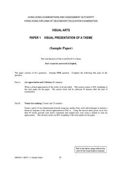
Fig. 3. Buckling coefficients and neutral surface locations of
circular plate vs ~dius-thickne~
ratios for (a) E”E’
= 0.2
and (b) E’/E’ = 2.0. S = 1; @= 0.
IV; = -hP,,
M;=
20
10 20
-h’P,,/12.
(29)
Now, we put p = P,,,jP,,, which represents the ratio of
bending pressure to compression pressure, and also
define the buckling coefficient K, as
solution of thin plate by Timoshenko 1201. It can be
shown that buckling coefficients with no bending
stresses for ordinary plate which are calculated in the
present paper coincide very well with Timoshenko’s
for clamped circular plate.
The buckling coefficients KC, for the circular and
annular plates are obtained in Figs 3-8. In the
computations, EC= 1.0, vc = 0.2, El/EC = 0.2-2.0 and
Y’ is given by the relation
v’= v’E’/E’.
(31)
The shear moduli G” and G’ in the respective compressive and tensile regions are
(30)
G” = EC/2(1 f V),
There are so many parameters that can be varied
that it would be difficuIt to present results for all
cases.
Only a few typical cases have been selected for
discussion here. For verifying the accuracy of present
results, the non-dimensional buckling coefficients of
ordinary (not bimodulus material) thin circular plate
are considered first. In Table 1, the present results for
ordinary circular plate are compared with the exact
Table 1. Comparison between the present results and exact
solutions in (201 for ordinary circular plates
IL/h
8
IO
20
50
loo
Resent
results
K,
13.549 13.934
14.495 14.661 14.685
Exact
K,
14.68
14.68
solutions
14.68
14.68
14.68
G’ = E’/2( 1 + v’).
(32)
Plots of f&/h vs K, and 2,/h for circular plates are
shown in Fig. 3 {a). The values of Et/EC, S and fi are
equal to 0.2, 1 and 0, respectively. It can be seen that
the buckling coefficients increase with increasing values of&/h. Owing to the non-dimensional coefficient
effect, the actual buckfing load N, which is equal to
hP, decreases with increasing radius to thickness
ratio. The neutral surface locations of thick plates are
further away from the middle plane than those of thin
plates. The conditions in Fig. 3(b) are the same as
those in Fig. 3(a) except that El/E’ = 2.0. The neutral
surface locations have the same trend as in Fig. 3(a).
The effects of transverse isotropic parameter
S = G*/G on k& and 2,/h for circular plates are
shown in Figs 4(a) and (b), where &/h = 10, j? = 0
and F/E’ is equal to 0.2 and 2.0, respectively. It is
seen that the larger the transverse isotropic coefficient
S is, the greater the buckling load is, and the further
I80
DAR-PIZG JUANG and LIEN-WEN CHEN
2
5.2 -
-0.1965
s.o-
-0.197
9
(a)
4
4
4.6
;
I
2
I
4
8
16
22[
s
IO.12
0.1033
20.75
t/
0.09
1
+j
0.08
Znlh
20.5 ~
3
0.4
20
P
l-O.198
8
6
12
0.103
iu’
0.07
‘“OW
20.25
1s
0.1025
0.06
20
P
Fig. 6. Buckfing coefficients and neutral surface locations vs
20
0.10:
1
2
4
i
8
bending stress ratio of circular plate for (a) El/E’ = 0.2 and
(b) E’jEc = 2.0. RJh = 10; S = 1.
s
Fig. 4. Buckling coefficients and neutra1 surface locations of
circular plate vs tranverse isotropic coeficients for (a)
Et/EC = 0.2 and (b) Et/EC = 2.0. R,,/h = 10; p = 0.
the neutral surface location moves away from the
midplane. Also, we can see that the effects of small
S have more influences than those of large S. This
means that the buckling load reduces and &//I
approaches the midplane when the transverse shear
resistance is small.
Plots of E/E’ vs K, and ZJh for circular plates are
shown in Fig. 5, where R,Jh = IO. S = I and fl = 0.
It is easy to be seen that the buckling coefficient K,
increases with increasing the Young’s modulus ratio
Et/EC due to the larger values of rigidity as Et/EC
increases, and the tensile zone decreases with increasing values of El/E’.
Plots of K, vs /I for circular plates are shown in
Figs 6(a) and (b), with h/h and S equal to IO and
1, respectively, and El/E’ equal to 0.2 and 2.0, re-
spectively. The bending stress effects can be seen to
reduce the buckling coefficient K,, when EC/EC c I
and increase it when El/E’ > 1. But the neutral
surface location is shifted down when /I is increased.
Owing to the shifts of the neutral surface locations,
the effects of bending stress on bimodulus materials
have much more influence than those on ordinary
materials (not bimodulus).
Figure 7 shows the neutral position Z,,/h and Z&/h
of annular plates for two cases in which the ratios of
‘,,I, , >/ , , 1
I ‘a’.
0 0.1 0.2 0.3 0.4 0.5 0.6 0.7 0.8 0.9 1.0
19 I?IS 2
13 -0.05
II-
75
0
- -0.2
0.4
0.8
1.2
1.6
2.0
Et/EC
Fig. 5.
,
c
- -0.1
9-
Buckling coefficients and neutral surface locations vs
modulus ratio of circular plate. &/h = IO; S = 1; p = 0.
@)
0
0.25
0.5 0.6 0.7 0.8 0.9 1
?I&
Fig. 7. Neutral surface locations 2,/h and 2,/h vs r/& of
annular plate with inner free-outer clamped boundary condition for (a) R,/h$ = 0.3; (b) RJR, = 0.5. E*/E’= 2.0;
S=1;/?=o;&/h=IO.
Axisymmetric buckling of bimodulus thick circular plates
j
/
I
0
0.2
6.0
I
0.4
0.6
0:s
181
(3) The buckling load increases with increasing
transverse isotropic coefficient S. The effect can be
seen more significantly when S < 2 for circular plates.
(4) The buckling load decreases with increasing
initial bending stress coefficient for E’/,!? c 1, and
with decreasing /l for E’/EC > I for circular plates.
(5) The buckling coefficient increases with increasing Et/EC for circular plates.
(6) The buckling of the annular bimodulus plates
is also studied. The Lame’s solution is found to have
an important effect.
The buckling and vibration problems of laminated
composite bimodulus circular plates need to be further studied. The results will be presented in the near
future.
RJR,
REFERENCES
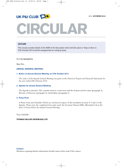
Pig. 8. Buckling coefficients K, of annular plates vs internal
radius-external radius ratios R,/& of an annular plate
with inner free-outer clamped boundary condition and with
inner free-outer simply supported boundary condition for
S. K. Clark, The plane elastic characteristics of cordrubber laminates. Textile Res. J. 33, 295-313 (1963).
E. J. Seldin, Stress-strain properties of polycrystalline
graphites in tension and compression at room temperature. C&on 4, 177-191 (1966).
S. A. Ambartsumyan and A. A. Khachatryan, The basic
equations of the theory of elasticity for materials with
different tensile and compressive stiffness. Meek. Solids
1, 29-34 (1966).
C. W. Bert, Classical analysis of laminated bimodulus
Et/E’ = 2.0; S = 0; j3 = 0; RJk = IO.
internal radius to external radius R,/& are 0.3 and
0.5, respectively, where E’/F, h/h, Sand fl are equal
to 2.0, 10, 1 and 0, and their boundary conditions are
free-clamped. The position Z,, is derived by err= 0
while Z,, is derived by 6~ = 0. It is seen that both 2,
and Z,, vary with position and Z,,? is not the same as
Z, in general, and this phenomenon does not take
place in cicular plates. It is believed that the Lame’s
distribution causes the result in the present study. We
shall take the approach that 2, =$.?nl -t- Z,,) to
solve the annular plates with isotropic bimodulus
material. Even though this approach is rough, it
provides an approach to complete this problem.
Plots of K, vs R&R,, for annular plates are shown
in Fig. 8, where Et/EC, fib/h, S and /l are equal to 2.0,
10, 1 and 0, respectively. The dashed line represents
the buckling with free-simply boundary condition,
while the solid line represents the buckling with
free-clamped boundary conditon in Fig. 8. We can
see that the buckling coefficient with free-clamped
boundary condition has the lowest value when Ri/&
equals approximately 0.16. It is also seen that the
buckling coefficients with free-simply boundary condition decrease with increasing the values of R,j&
while the one with free-clamped condition has the
reverse effect.
com~site-mate~al plates. University of Oklahoma,
School of Aerospace, Mechanical and Nuclear En5.
6.
7.
8.
9.
10.
11.
12.
COFiCLUSlONS
13.
The following conclusions can be drawn from the
prelimina~ results presented.
(1) The present finite strip method can produce
accurate buckling analysis of a circular plate,
(2) The thicker the plate is, the lower the buckling
coefficient K, is; the buckling loads N,( = hP,) of
thick circular plates are larger than those of thin
circular
plates.
14.
15.
16.
17
. r.
gineering, Contract No. NO001478-C-0647 Report
OU-AMNE-79.1OA (1979).
C. W. Bert, Model for fibrous composites with different
properties in tension and compression. J. &gng Mar.
?echnol. ASME 99H, 344-349 (1979).
_ _
C. W. Bert. V. S. Reddv and S. K. Kincannon.
Deflection of thin rectangular plates of cross-plied
bimodulus material. J. &rue<. Meek. 8,347-364 (I 980).
J. N. Reddy and C. W, Bert, Analyses of plates
contructed of fiber-reinforced bimodulus materials.
Mech. Bimodulus Mat. AMD 33, 67-83 (1979).
C. W. Bert, Bending of thick rectangular plates Iaminated of bimodulus materials. AIAA J. 19, 1342-1349
(1981).
C. W. Bert, 3. N. Reddy, W. C. Chao and V. S. Reddy,
Vibration of thick rectangular plates of bimodulus
composite material, J. appi. Meek. ASME 48, 371-376
(1981).
N. Kamiya, Large deflection of a different modulus
circular plate. J. Engng Maf. TecknoL ASME 97H,
52-56 (1975).
N. Kamiya, An energy method apphed to large elastic
deflection of a thin plate of bimodulus material. J.
Srruct. Mech. 3, 317-329 (1975).
J. L. Doong and L. W. Chen, Axisymmetric vibration
of an initially stressed bimodulus thick circular plate. J.
Sound Vi&r. 94, 461-468 (1984).
E. J. Brunelle and S. R. Robertson, Initiaily stressed
Mindiin plates. AIAA J. 12, 10361044 (1974).
R. M. Jones, Buckling of circular cylindrical shells with
different moduli in tension and compresion. AIAA J. 9,
53-61 (1971).
R. M. Jones, Buckling of stiffened multilayered circular
cylindrical shells with different orthotropic moduli in
tension and compression. AIAA J. 9, 917-923 (1971).
J. S. Przemieniecki, Finite element structural analysis of
local instability. AIAA J. 11, 33-39 (1973).
G. C. Pardoen, Static, vibration and buckling analysis
DAR-PKG JUANGand LIEN-WENCHES
182
of axisymmetric circular plates using finite elements.
Compur. Srrucf. 3, 355-375 (1973).
18. G. C. Pardoen, Asymmetric vibration and stability of
circular plates. Comput. Srrucr. 9, 89-95 (1978).
19. M. N. Bapu Ras and K. S. S. Kumaran, Finite element
analysis of Mindlin plates. i. ,Mech. Des. AS&ME101,
619624 (1979).
20. S. Timoshenko and S. Woinowsky-Krieger, Theory of
Plates and Shells, 2nd Edn. McGraw-Hill, New York
(1959).
21. L. W. Chen and J. L. Doong. Vibrations of an initially
stressed transversely isotropic circular thick plate. Inr. J.
.\-iech. Sci. 26. 253-263 (19S4).
22. Y. C. Fung. fbundarions of Solid Mechanics, p. t 14
Prentice-Hall. Englewood ClifTs, NJ (1965).
23. Y. K. Cheung, Finite Strip Merhod in Structural
Analysis, p. 3 (1976).
24 J. L. Doong and L. W. Chen, Buckling of a bimodulus
composite thick plate. Failure Prevention and Reliability Conference. ASME, pp. 95-200 (1983).
APPENDIX
a
ar
I
EP
0
-
11
-
r
r
a
a
a
ae
1
ra8I--J
ar
0
0
0
0
0
00
0
00
0
00
a
1
ar
0
;
k_
r
000;
000
F=
000;
1t
1
a
2
The reduced materiai elastic constants are
E
vE
I -tt’l
1-c2
VE
-I-v’
l-v?
--
Q==
E
00
0
00
0
0
OGO
0
0
0
k?G*
0
0
0
0
0
k’G*
0


© Copyright 2026