
ipDataTel CDMA-BAT Installation
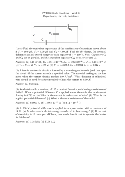
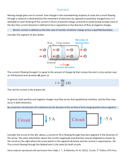
ipDataTel CDMA-BAT Installation
This guide is for our customers who want to install the ipDataTel equipment
before their programming appointment. This guide covers installing the IPDCDMA-BAT with Vista, DSC, or Caddx systems in detail. If you would like assistance
through the full installation process or you do not have a Vista/First
Alert/Safewatch Pro, DSC, or Caddx alarm system please contact us at 800-6246866. In these cases you must schedule an appointment, as the connection
cables and wiring will vary substantially from this guide depending on the panel
you have. If you have any questions regarding this guide please feel free to call
us.
When you first receive your IPDataTel it will look like this:
1
You will also receive 2 alarm connection cables that look like this:
NOTE: One antenna will also be in the box your IPD unit shipped in.
What you will need to install:
-A small flathead screwdriver
2
Step 1: The first thing you need to do is remove the cover on the IPDataTel CDMA
Broadband Alarm Transmitter (the white box) to expose the internal circuit board.
There are tabs on the bottom of the case that you can press down to crack open
the case. This is what the circuit board looks like:
NOTE: As you can see there are 16 screw terminals adjacent to the left side of the
board. We will be wiring from this board to the alarm panel circuit board later on
in this guide.
3
You can go ahead and attach the antenna that was in the box to the IPDataTel as
shown below:
4
Step 2: You will need to power down your alarm system as you will be working
with low voltage. In order to do this you will want to disconnect the AC adapter or
transformer for the alarm system from the wall outlet. If there is no transformer
because the power wires are going into the wall behind the panel then you can
disconnect one of the AC wires going to your alarm panel. Most often the AC
wires are located on the first 2 terminals from the left on your alarm panel circuit
board. You will also disconnect one of the leads going to the backup battery for
your alarm system. You can disconnect red or black, it does not matter. Once you
have verified that there is no power going to the system (no power to the keypad)
you are ready to move to the next step.
Step 3: The wiring from the IPDataTel will go to certain terminals on your system’s
circuit board, depending on your panel. This section shows you circuit boards for
the most common and supported panels with the IPDataTel and which terminals
to connect the wires to. Reference the wiring scheme for your particular panel
type to ensure that the connections are made properly.
NOTE: When you are wiring to your alarm system, make sure you run any
cables/wires through any available holes in your control panel enclosure so that
you can ultimately close the alarm panel box once the installation is complete.
The same applies to wires that are connected to the ipDataTel.
5
Vista Circuit Board Wiring
As you can see on the Vista panel there are about 25 screw terminals down the
bottom. You will take the cable that has 4 different colored wires (red, black,
green, and yellow) exposed on each end and screw them in to the terminals in the
following order (refer to pg. 13 for diagram):
Terminal 4 from the left: Black wire
Terminal 5 from the left: Red wire
Terminal 6 from the left: Green wire
Terminal 7 from the left Yellow wire
You’ll notice that there are other wires already going to these terminals. Those
wires will stay there along with the newly installed wires. Do not remove them as
they are typically responsible for your keypads. Now you will want to take the
cable that has 2 exposed wires on each end (red and green) and then connect the
wires to the terminals on the alarm circuit board in the following order:
Terminal 24 (2nd terminal from the right): red wire
Terminal 23 (3rd terminal from the right): green wire
6
NOTE: You may already have wires going to terminals 21-24 on the Vista system
before connecting the wires we shipped you. Disconnect any wires going to
terminals 21-24 before connecting the wires we supplied.
If you have made the connections as mentioned above, you may move to Step 4
(pg. 10).
DSC Power Series Circuit Board Wiring
As you can see, this panel has about 25 screw terminals down the bottom of the
board. Using the cable with 4 different color wires on each end, you will wire up
to the panel as follows (refer to pg. 14 for diagram):
Terminal RED from the left: red wire
Terminal BLK from the left: black wire
Terminal YEL from the left: yellow wire
7
Terminal GRN from the left green wire
You’ll notice that there are other wires already going to these terminals. Those
wires will stay there along with the newly installed wires. Do not remove them as
they are typically responsible for your keypads. Now you will want to take the
cable that has 2 exposed wires on each end (red and green) and then connect the
wires to the terminals on the alarm circuit board in the following order:
Terminal Ring from the right: red wire
Terminal Tip from the right: green wire
NOTE: You may already have wires going to terminals TIP, RING, R1, and TI on the
DSC system before connecting the wires we shipped you. Disconnect any wires
going to these terminals before connecting the wires we supplied.
If you have made the connections as mentioned above, you may move to Step 4
(pg. 10).
8
Caddx NX Series Wiring Diagram
As you can see, the terminals we need to connect to on this system circuit board
are Data, Com, Positive, Red, and Green. Sometimes, they are labeled KP Data, KP
Com, and KP Positive as well. You will wire the cable with the 4 wires on each end
(red, green, black, and yellow) to this panel (refer to pg. 15 for diagram).
Terminal Data : Green
Terminal Com: Black
Terminal Positive: Red
The yellow wire on this cable will not be used. Just leave it to the side or snip it
off.
9
You’ll notice that there are other wires already going to these terminals. Those
wires will stay there along with the newly installed wires. Do not remove them as
they are typically responsible for your keypads. Now you will want to take the
cable that has 2 exposed wires on each end (red and green) and then connect the
wires to the terminals on the alarm circuit board in the following order:
Terminal Red from the top: red wire
Terminal Green from the top: green wire
NOTE: You may already have wires going to terminals Gray, Red, Green, and
Brown on the Caddx system before connecting the wires we shipped you.
Disconnect any wires going to these terminals before connecting the wires we
supplied. If you have made the connections as mentioned above, you may move
to Step 4.
Step 4: The next step is to wire the other ends of the two cables you connected to
the alarm panel terminals to the terminal strip on the IPDataTel (black circuit
board). This is what the terminal strip looks like:
NOTE: The wires need to be inserted through the square shaped holes (terminals)
that are part of the green terminal strip. The screws should already be loosened
so you will just need to tighten them.
10
Using the cable with the 2 wires on each end:
Terminal 1: wire the green wire to this terminal.
Terminal 2: wire the red wire to this terminal.
Using the cable with the 4 wires on each end:
Terminal 3: wire the red wire to this terminal.
Terminal 4: wire the black wire to this terminal.
Terminal 5: wire the yellow wire to this terminal.
Terminal 6: wire the green wire to this terminal.
Step 5: Power up the Alarm Panel. To do this you will reconnect the battery leads
first and then connect the transformer (ac adapter) to the wall outlet OR if you
disconnected the AC wire to the left-most terminal on the panel you will want to
reinsert that wire and secure it.
11
Step 6 (optional): Plug an Ethernet cable (CAT-5 or higher) into the RJ-45 jack on
the IPDataTel circuit board and run that cable to an open port on your router.
Step 7: Congratulations. You have successfully installed and configured the
product. Seal the IPDataTel CDMA BAT enclosure and your alarm panel box. You
can mount the IPDataTel on the wall if you would like. Then you will need to
contact us at 800-624-6866 to schedule a programming appointment if you have
not done so already.
12
Appendix
Ademco Vista Series Panel Wiring Diagram with Relevant Terminals Highlighted
13
DSC Power Series Panel Wiring Diagram With Relevant Terminals Highlighted
14
Caddx NX Series Panel Wiring Diagram With Relevant Terminals Highlighted
15


© Copyright 2026