
Smoot, Sara - Airborne Wind Energy Conference 2010
STABILITY OF PLATFORMS
FOR AIRBORNE WIND
TURBINES
Sara Smoot
Advised by Ilan Kroo
Stanford University
2
Motivation
Initial attempts at flying a tethered glider
3
Introduction
Goal: Develop a design analysis tool to compare the
dynamics of tethered air platforms.
• Use existing aerodynamic analysis tools
• Simple model with minimal tether dynamics
• Low altitude, ie. short tether
• Thin, light tether
• Evaluate stability
• Investigate modal dynamics
• Facilitate intuition for dynamics
• Accommodate rapid design iteration
How will design elements effect
stability?
4
Approach
Adapt linear airplane equations of motion to tethered wings
•
•
•
•
•
Develop a model that includes tether dynamics
Choose a set of states that describe the system
Linearize about a convenient operational point
Check for decoupling
Extract information about linearized modes
Compare results to tethered gliders
•
•
Qualitative comparison of linearized modes
Qualitative stability comparison
5
Airplane Summary
Aircraft dynamics are linearized around operational
points
• Reduce the aircraft dynamics to 8 dimensionless states:
• {𝛼, 𝜃, 𝑢} Angle of attack, Pitch Angle, Forward Velocity
• {𝛽, ϕ, ϕ, 𝜑, 𝜑} Side Slip, Roll,
Roll Rate, Yaw, Yaw Rate
States decouple for
steady level flight
• Longitude {𝛼, 𝜃, 𝑢}
• Lateral {𝛽, ϕ, ϕ, 𝜑, 𝜑}
http://www.grc.nasa.gov/WWW/K-12/airplane/rotations.html
6
Simplified Model: Tether
The tether is represented as a thin, light rod
attached to the ground by a ball hinge.
States from the tether are the Euler
rotations about the inertial X Y Z
frame.
Z
Down Wind
Y
X
7
Simple Model: Wing + Bridle
The bridled wing is connected to the tether by another ball hinge and is
treated as a rigid body.
States are the Euler rotations measured along the vector from the bridal joint to the
center of mass.
An additional rotation about the standard body x axis is included.
Depending on the type of bridle the wing can roll independently.
cg
Z
X
Y
8
Equations of Motion
Aerodynamic Moments from Wing
Gravitational Force on Wing
Tether Rotational Rates
Aerodynamic Forces from Wing
Bridle Rotational Rates
Tether Drag
Wing Rotational Rates
Tether Tension
9
Linearized States
Linearize around the static downwind state to obtain the
linear system:
The states can be ordered such that matrix
diagonal
Lateral States
Longitudinal States
is block
10
Linearized Longitudinal Modes
Tether
Bridle Pendulum
Pendulum Mode
Mode
Example Eigen Values
-0.4142 + 1.2527i -8.7413 + 1.9330i
-0.4142 - 1.2527i -8.7413 - 1.9330i
Associated Eigen Vectors
-0.1879 - 0.5683i -0.0001 - 0.0003i
0.7897
0.0017 + 0.0026i
0.0738 - 0.0342i 0.1084 + 0.0240i
0.0123 + 0.1066i -0.9938
Approximate Tether
Pendulum Frequency
11
Lateral Linearized Modes
Five Lateral Modes
• Roll Subsistence
• Modified Dutch Roll
• Yaw Subsistence
• Lateral Tether Pendulum
• Coupled Roll
12
Lateral Modes
Roll
Subsistence
Example
Eigen Values
-467.73
Associated
Eigen Vectors
-0.0002
0.0958
0.0002
-0.0816
-0.0000
0.0009
-0.0021
0.9920
• Roll subsistence: equivalent to airplane roll subsistence
• Absent when roll is bridled
13
Lateral Modes
Modified Dutch
Roll
Example
Eigen Values
-9.57 + 6.43i
-9.57 - 6.43i
Associated
Eigen Vectors
0.0480 + 0.0192i
-0.5830 + 0.1252i
-0.0492 - 0.0331i
0.6838
0.0006 + 0.0004i
-0.0079 + 0.0000i
-0.0285 - 0.0215i
0.4110 + 0.0220i
• Modified Dutch Roll: equivalent to airplane Dutch Roll
14
Lateral Modes
Yaw
Subsistence
Example
Eigen Values
-10.24
Associated
Eigen Vectors
-0.0483
0.4944
0.0797
-0.8167
-0.0009
0.0092
0.0275
-0.2813
• Yaw Subsistence
• Return to downwind position
15
Lateral Modes
Coupled Roll
Example
Eigen Values
-0.0001 + 0.0086i
-0.0001 - 0.0086i
Associated
Eigen Vectors
-0.0159 + 0.1096i
-0.0939 - 0.0148i
-0.0341 + 0.0130i
-0.0108 - 0.0294i
0.5294 - 0.0110i
0.0040 + 0.4544i
0.5309
-0.0055 + 0.4556i
• Coupled Roll
• All the derivatives effect this one
• Trade off with Pendulum mode
16
Lateral Modes
Lateral Tether
Pendulum
Example
Eigen Values
-.43 + .77i
-.43 - .77i
Associated
Eigen Vectors
0.7203
-0.3062 + 0.5566i
0.0565 - 0.1600i
0.0997 + 0.1117i
-0.0191 - 0.0795i
0.0695 + 0.0190i
0.0538 - 0.0728i
0.0334 + 0.0725i
• Lateral Tether Pendulum
• Lateral swinging of tether ball joint
17
Flight Demonstration
Dominate Modes:
Lateral Pendulum
Modified Dutch Roll
18
Flight Tests Qualitative Comparison
Built 23 different wings and varied:
• Tail length and Size
• Sweep
• Dihedral and multiple dihedral joints
• Span
• Horizontal Tail
Simulation
• Aerodynamic forces and moments
computed using AVL
• EQM integrated using MATLAB ode45
• Trim was found by running an interpolated
quasi linear aero-model
19
Qualitative Stability Check
Stable
1
Tested
Model
2
3
4
5
6
7
8
9
10 11
Marginally Stable
Unstable
12 13 14 15 16 17 18 19 20 21 22 23
20
Design Trends
Locus of Lateral Modes with Change in Dihedral Angle
Modified Dutch Roll
•
•
Built Designs
No Dihedral
Dihedral Decreases Roll
Subsistence Decay Time
Dihedral Decreases Dutch
Roll Damping
Roll Subsistence
21
Design Trends
Locus of Lateral Modes with Change in Dihedral Angle
•
•
Modified Dutch Roll
Built Designs
No Dihedral
Dihedral Decreases Roll
Subsistence Decay Time
Dihedral Decreases
Damping Dutch Roll
Yaw Subsistence
Dihedral Decreases Yaw
Subsistence Decay Time
22
Design Trends
Locus of Lateral Modes with Change in Dihedral Angle
•
•
Coupled Roll
Built Designs
No Dihedral
Dihedral Decreases Roll
Subsistence Decay Time
Dihedral Decreases
Damping Dutch Roll
Lateral Pendulum
Dihedral Decreases Yaw
Subsistence Decay Time
Dihedral Decreases Lateral
Pendulum Damping
23
Design Trends
Locus of Lateral Modes with Change in Dihedral Angle
•
•
Built Designs
No Dihedral
Dihedral Decreases Roll
Subsistence Decay Time
Dihedral Decreases
Damping Dutch Roll
Dihedral Decreases Yaw
Subsistence Decay Time
Dihedral Decreases Lateral
Pendulum Damping
Dihedral Increases Coupled
Roll Stability
Coupled Roll Mode
24
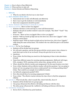
Design Trends: Aspect Ratio
25
Conclusions
• A simple model of airborne tethered
wings gives useful information
• Linearization can be an effective tool
for:
• Low Fidelity Design Optimization
• Demonstrating effect of design elements
on dynamics modes
• Evaluating stability
• Next Steps
• Develop a linearized tether model for high
altitude systems and thick tethers
• Analyze the usefulness of the model for
control design


© Copyright 2026