
Temperature-calibrated fiber-optic refractometer based on a
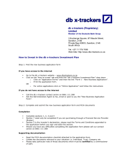
COL 10(03), 030604(2012) CHINESE OPTICS LETTERS March 10, 2012 Temperature-calibrated f iber-optic refractometer based on a compact FBG-SMS structure Qiangzhou Rong (J Jr ± )1∗ , Xueguang Qiao (z zÆ 1 )1 , Tuan Guo (H H ì )2 § Ruohui Wang ( e z )1 , Jing Zhang (Ü Ü Ã )1 , Manli Hu ( ÷ | )1 , Zhongyao Feng (¾ ¾§ )1 , 1 1 Yinyan Weng (± ±Õ ÿ ) , and Yue Ma (ê ê T) 1 Department of Physics, Northwest University, Xi’an 710069, China Institute of Photonics Technology, Jinan University, Guangzhou 510632, China ∗ Corresponding author: [email protected] Received July 5, 2011; accepted August 31, 2011; posted online November 18, 2011 2 A novel all-fiber temperature-calibrated refractometer based on a compact fiber Bragg grating (FBG) single–multi–single (SMS) structure is proposed and experimentally demonstrated. The sensor head is composed of a FBG combined with a SMS structure, in which the middle multimode fiber (MMF) section is etched by a time-controlled hydrofluoric. The transmission dip of SMS is extremely sensitive to ambient refractive index (RI) variation, whereas the upstream FBG provides the necessary temperature information for RI calibration. All aforementioned functions are performed via a compact FBG-SMS structure not longer than 25 mm. The proposed sensing device provides a linear RI sensitivity over water or waterbased solutions (RI values near 1.33 at optical wavelengths for most biological and many environmental applications), and has temperature-calibration capability. Hence, the said refractometer is a good candidate for sensing in chemical and biological applications. OCIS codes: 060.2370, 060.3735. doi: 10.3788/COL201210.030604. Optic fiber sensors have been widely used for a number of parameter measurements, such as temperature, strain, curvature, vibration, humidity, and so on[1−6] . Compared with conventional electric sensors, optic fiber sensors have very attractive advantages, including long-distance transmission and broad bandwidth, multiplexing capability, and no electromagnetic interference. Therefore, optic fiber sensors are suitable for hazardous and highly secure environments, such as nuclear power plants, oil, and gas wells. In contrast, refractive index (RI) measurement based on fiber devices has become increasingly important in various applications, including chemical, biological, and environmental monitoring. Methods implementing RI sensing abound, such as thinned fiber Bragg grating (FBG)[7] , longperiod grating (LPG)[8] , tilted FBG[9,10] , and FabryPerot interferometer[11] . These techniques take advantage of all fiber operations. However, they suffer from complex structure and fabrication process. The designing of sensors of better quality at a lower cost encourages further research. A novel all-fiber temperature-calibrated refractometer based on a single–multi–single (SMS) mode structure with FBG is proposed in this letter. SMS combined with fiber structure of FBG as temperature or strain has been previously demonstrated[12] . The middle multimode fiber (MMF) section is etched under time-control and functions as a Mach-Zehnder interferometer (MZI) in this letter. A sharp dip in transmission spectrum exists due to the multimode interference effect. The etched SMS structure is extremely sensitive to ambient RI and shows a linear response over low RI values of 1.33–1.39, which is an extreme concern in biochemical fields. Meanwhile, the upstream FBG provides the necessary temperature information for RI calibration. The 1671-7694/2012/030604(3) proposed sensor is a good candidate for sensing in chemical and biological applications. The proposed temperature-calibrated refractometer is based on FBG cascaded on a SMS structure, as shown in Fig. 1. (a) Schematic diagram of FBG-SMS refractometer, photographs of SMS section (b) before and (c) after HF etching, and (d) cross-section interface of MMF section after HF etching. 030604-1 c 2012 Chinese Optics Letters ° COL 10(03), 030604(2012) CHINESE OPTICS LETTERS Fig. 1(a). The SMS fiber structure is fabricated using a Fujikura CT-30 cleaver and a Fujikura arc fusio splicer (FMS-60S). The splice is performed manually by an arc discharge (I=10.4 mA, t=1.5 s). The FBG is combined upstream to the SMS. In the SMS structure, the center MMF has a step-index distribution with core diameter of 105 µm and cladding diameter of 125 µm. As shown in Fig. 2, the interference spectral wavelength spacing of SMS decreases when MMF length increases, consistent with previous records[11] . Experiments have been carried out with MMF samples not longer than 25 mm. To improve the sensitivity of MMF to the ambient RI fluctuations, the hydrofluoric acid (HF) corrosion (40% concentration) is used to etch the fiber cladding of the optical fiber to the optimized thickness. Because of the composition differences of single-mode fiber (SMF) and MMF cladding, a slight etching thickness difference has been found. MMF is etched faster than that of the SMF. Thus, the diameter of the MMF region is smaller than that of SMF section, as shown in Figs. 1(b) and (c). The chemical reaction differences are due mainly to the fiber structure and composition. The HF reaction in the silica matrix can be generally expressed as SiO2 +6HF→2H2 O+ +H2 SiF6 , whereas, in the case of the Ge-doped cladding of the MMF section, the chemical reaction can be expressed as GeO2 +6HF→2H3 O++GeF2− 6 . The chemical reaction is faster in the Ge-doped silica matrix of the MMF section because of the relatively lower covalent bond energy; in contrast, it is slower in the case of the pure silica matrix in the core and SMF cladding[13] . The whole process of HF-etching is finished at room March 10, 2012 temperature for 4 min. During the etching process, the transmission dip of SMS structure shows a blue shift approximately tens of nanometers over 4 min of etching, as shown in Fig. 3. Hence, the corrosion process can be controlled precisely by monitoring the transmission spectrum of SMS structure. The diameter of MMF is 57.92 µm, which is achieved eventually, as shown in Fig. 1(d), and the picture is achieved via optical microscope (Nikon ECLIPSE LV100). The temperature-sensing mechanisms of FBGs and SMS structure have been demonstrated in Refs. [1,2]. According to Ref. [2], the relationship between the wavelength shift of SMS transmission dip based on multimode interference and temperature variations can be given as 4λ = (α + ζ) ∆T, λ (1) where α and ζ are the thermal expansion coefficient (TEC) and the thermo-optic coefficient (TOC) of SMS structure material, respectively. For silica fiber, α = 5 × 10⁻⁷ /◦ C and ζ = 6.9 × 10⁻⁶ /◦ C[2] . Notably, TEC and TOC of the MMF section of the SMS structure will not change after etching in HF. Hence, etching will not affect their temperature sensitivity. The light injected from the SMF into the MMF will excite multiple high-order modes in MMF and will be transmitted along the MMF with different propagation constant βm , similar to the planar waveguide coupler based on MZI. Assuming that the SMF and MMF are ideally aligned, only LP0m modes will be excited in the MMF when light travels from SMF to MMF because of the circular symmetry of the input field. The different modes will interfere and recouple back into the SMF at the second splice. The light interference spectrum is determined when only the high-order modes are considered[1] : ³ 2π∆nL ´ p I = I1 + I2 + 2 I1 I2 cos , (2) λ where I1 and I2 are the powers distributed in the firstand second-order modes, respectively; I is the measured power; L is the length of MMF; λ is the light wavelength in vacuum; ∆n is the difference of the two lowest-order mode indices. According to Eq. (2), the wavelength spacing ∆λ of the interfering spectrum is given as Fig. 2. Transmission spectra of different length MMFs. ∆λ ≈ Fig. 3. Spectral evolution of SMS structure during timecontrolled HF etching. λ2 . ∆nL (3) Equation (3) shows that ∆λ and free spectral rage (FSR) decrease as the length of MMF sandwiched increases. Different numbers of interference dips exist for all four fabricated interferometers with varying lengths, as shown in Fig. 2. For example, when L = 20 mm, one interference dip exists and the wavelength is 1 594.32 nm. However, when L = 40 mm, three dips exist and the wavelengths of the dips are 1 524.42, 1 575.82, and 1 596.83 nm, respectively. The experimental results are consistent with Eq. (3). In contrast, the interference spectra are sensitive to the variation of ambient RI temperature changes because of the differences of thermooptic dependence of the effective refractive indices of the first two lowest-order modes, resulting in the shift in interference dips. In the experiment, a broadband source and an optical 030604-2 COL 10(03), 030604(2012) CHINESE OPTICS LETTERS spectrum analyzer (OSA) with a resolution of 0.05 nm are used, as shown in Fig. 4. The SMS sensing head is immerged in water-glycerin solutions with varying concentrations for different RI. The transmission dip of the sensor is scanned via OSA. To eliminate the impact of fiber bending and stress, two fiber holders are used to keep the sensor straight and the strain constant. The fiber sensor is immersed in the water-glycerin solutions of varying concentrations for different RIs certified by N Abel refractometers. The transmission spectra change with the RI fluctuations in the region labeled “zone A” (the interference dip of SMS structure), as shown in Fig. 5. More importantly, the wavelength of transmission dip provides a linear red shift with the sensitivity of ∼200 nm/RIU (RIU: RI unit) over the low range of 1.33–1.39, which is essential for most water or waterbased biochemical sensing applications. In addition, RI sensitivity gradually increases for higher RI liquid measurement over the range of 1.40–1.45, with a maximum RI sensitivity of 800 nm/RIU. In contrast, in the region labeled “zone B” with a fixed environmental temperature, the five curves (response to five different RIs) overlap with each other exactly over their Bragg reflection, providing an accurate temperature-calibration forany slight thermal fluctuation. The FBG-SMS sensing head is adhered on the heating plate, the temperature error of which is ±1 o C, as shown in Fig. 4. The SMS structure is sensitive to temperature change because of the differences in thermooptic dependence of the effective refractive indices of the high-order modes. The wavelength shift of SMS interferometer dip and FBG reflection versus temperature of 25–90 o C. Good linear responses have been identified with temperature sensitivities of 0.0120 nm/o C for SMS and 0.0109 nm/o C for FBG, as shown in Fig. 6. A novel all-fiber temperature-calibrated refractometer based on a compact FBG-SMS structure is proposed and experimentally demonstrated. The proposed sensor is compact, with a length not longer than 25 mm, and Fig. 4. Schematic of the experimental setup for RI and temperature measurement. Fig. 5. Spectral evolution of SMS sensing device versus RI while temperature is fixed. March 10, 2012 Fig. 6. Wavelength shifts of SMS and FBG versus temperature fluctuation. provides linear RI sensitivity over water or water-based solutions (RI values near 1.33 at optical wavelengths for most biological and many environmental applications). Moreover, the mentioned refractometer has temperaturecalibration capability. The characteristics above make it a good candidate for sensing in chemical and biological applications. This work was supported by the National Natural Science Foundation of China (Nos. 60727004 and 61077060), the National “863” Program of China (Nos. 2007AA03Z413 and 2009AA06Z203), the Ministry of Education Project of Science and Technology Innovation (No. Z08119), the Ministry of Science and Technology Project of International Cooperation (No. 2008CR1063), the Shaanxi Province Project of Science and Technology Innovation (Nos. 2009ZKC01-19 and 2008ZDGC-14), the Guangdong Nature Science Foundation of China (No. S2011010001631), and the Fundamental Research Funds for the Central Universities of China (No. 11611601). References 1. D. Zhou, L. Wei, W. Liu, Y. Liu, and J. W. Y. Lit, Appl. Opt. 47, 1668 (2008). 2. E. Li, Opt. Lett. 32, 2064 (2007). 3. O. Fraz˜ ao, L. M. Marques, S. Santos, J. M. Baptisa, and J. L. Santos, IEEE Photon. Technol. Lett. 18, 2407 (2006). 4. Y. Wang and Y. Rao, IEEE Sensors Journal 5, 839 (2005). 5. L. Gao, S. Liu, Z. Yin, L. Zhang, L. Chen, and X. Chen, IEEE Photon. Technol. Lett. 23, 18 (2011). 6. B. Gu, M. Yin, A. P. Zhang, J. Qian, and S. He, Opt. Express 19, 4140 (2011). 7. A. Iadicicco, A. Cusano, and S. Campopiano, IEEE Sensors Journal 5, 1288 (2005). 8. M. Jiang, A. P. Zhang, Y. Wang, and H. Ta, Opt. Express 17, 17976 (2009). 9. C. Caucheteur, P. M´egret, and A. Cusano, Appl. Opt. 48, 3945 (2009). 10. T. Guo, C. Chen, A. Laronche, and J. Albert, IEEE Photon. Technol. Lett. 20, 635 (2008). 11. Y. Gong, Y. Guo, Y. Rao, T. Zhao, and Y. Wu, IEEE Photon. Technol. Lett. 22, 1708 (2010). 12. E. Li, IEEE Photon. Technol. Lett. 19, 1266 (2007). 13. V. R. Machavaram, R. A. Badcock, and G. F. Fernando, Sensors and Actuators A 138, 248 (2007). 030604-3


© Copyright 2026