
Radioactive Sodium Waste Treatment and Conditioning Review of Main Aspects IAEA-TECDOC-1534
IAEA-TECDOC-1534
Radioactive Sodium Waste
Treatment and Conditioning
Review of Main Aspects
January 2007
IAEA-TECDOC-1534
Radioactive Sodium Waste
Treatment and Conditioning
Review of Main Aspects
January 2007
The originating Section of this publication in the IAEA was:
Waste Technology Section
International Atomic Energy Agency
Wagramer Strasse 5
P.O. Box 100
A-1400 Vienna, Austria
RADIOACTIVE SODIUM WASTE TREATMENT AND CONDITIONING
IAEA, VIENNA, 2007
IAEA-TECDOC-1524
ISBN 92–0–116006–2
ISSN 1011–4289
© IAEA, 2007
Printed by the IAEA in Austria
January 2007
FOREWORD
Sodium and sodium–potassium eutectic (NaK) have been used as coolants in several
research reactors as well as in a small group of prototype and commercial nuclear reactors
with fast neutrons. Some of the reactors are still in operation; however, most of them have
been already shut down either for their age or for economic reasons. Sophisticated sodium
cooled reactors with fast neutrons are considered as a prime candidate for the next generation
of future reactors with advanced fuel cycles maximizing resource utilization and minimizing
waste production.
Radioactive sodium waste management is not covered in the IAEA publications. Only
general and limited information is available in publications dealing with decommissioning of
nuclear reactors. Recognizing this fact and the requirements of the Member States, the
Agency prepared this publication to address specific issues of radioactive sodium waste
handling, processing and disposal in the global context of management of radioactive waste
from operation through decommissioning of nuclear facilities.
The first draft report was prepared at the meeting 18–22 June 2001 by four consultants:
M. Berte (France), N. McLean (United Kingdom), B. Michelbacher (United States of
America) and Yu. Shtynda (Russian Federation). The status report on the subject was
prepared by M. Berte. The technical meeting (TM) was held in April 2002 in Lyon, organized
by IAEA in cooperation with Framatome ANP. Ten participants from nine countries
discussed various aspects of radioactive sodium waste management and contributed to
substantial improvement of the draft publication. At the meeting 5–9 May 2003, N. McLean
(United Kingdom), B. Michelbacher (United States of America) and S. Nakai (Japan)
consolidated all comments and prepared a final draft publication. A subsequent consultant’s
review was performed by J.J. Kelly (United States of America) 3–6 March 2006 for editorial
purposes, structural revisions, and verification the contents remain reliable and relevant.
The IAEA wishes to express its appreciation to all those individuals who took part in
the preparation and publication of this report. Particular acknowledgement is due to M. Berte
(France), who chaired the TM and put great effort into the completion and technical polishing
of this publication.
The officer at the IAEA responsible for initiating this report was R. Burcl from the
Division of Nuclear Fuel Cycle and Waste Technology. J.L. González Gómez and J.J. Kelly
of the same Division finalized the report for publication.
EDITORIAL NOTE
The use of particular designations of countries or territories does not imply any judgement by the
publisher, the IAEA, as to the legal status of such countries or territories, of their authorities and
institutions or of the delimitation of their boundaries.
The mention of names of specific companies or products (whether or not indicated as registered) does
not imply any intention to infringe proprietary rights, nor should it be construed as an endorsement
or recommendation on the part of the IAEA.
CONTENTS
SUMMARY.......................................................................................................................1
1.
INTRODUCTION ............................................................................................................ 3
1.1.
1.2.
1.3.
1.4.
2.
Background.............................................................................................................. 3
Objective ................................................................................................................. 3
Scope ....................................................................................................................... 4
Structure .................................................................................................................. 4
GENERAL CONTEXT OF SODIUM WASTE GENERATION .................................... 5
2.1. Status of liquid metal cooled reactors ..................................................................... 5
2.2. Hazards associated with alkali metals ..................................................................... 6
2.2.1. Reaction with water ....................................................................................... 6
2.2.2. Reaction with air and oxygen......................................................................... 6
2.2.3. Specific hazards associated with NaK ........................................................... 6
2.3. Sodium waste generation during reactor pre-commissioning ................................. 7
2.4. Sodium waste generation during REACTOR operation ......................................... 7
2.5. Sodium waste generation during REACTOR decommissioning ............................ 8
2.6. Specific aspects of sodium cooled reactor decommissioning strategy.................... 9
3.
SODIUM AND SODIUM-POTASSIUM WASTE IN THE
CONTEXT OF LMFR DECOMMISSIONING AND
DISMANTLING ............................................................................................................. 10
3.1. Bulk sodium from main circuits............................................................................ 10
3.1.1. Quantities ..................................................................................................... 10
3.1.2. Radiological inventory................................................................................. 10
3.1.3. Chemical purity............................................................................................ 12
3.1.4. Main waste management problems.............................................................. 13
3.2. Residual sodium from reactor main circuits after draining ................................... 13
3.2.1. Draining of reactor circuits .......................................................................... 13
3.2.2. Quantities ..................................................................................................... 15
3.2.3. Radiological aspects..................................................................................... 16
3.2.4. Main waste management problems.............................................................. 16
3.3. Removable components from main circuits .......................................................... 16
3.4. Other sodium wetted metallic items from circuits ................................................ 17
3.5. Cold traps .............................................................................................................. 18
3.6. Caesium traps ........................................................................................................ 19
3.7. Secondary (drummed) sodium waste .................................................................... 19
4.
SODIUM WASTE TREATMENT PROCESSES.......................................................... 20
4.1. Introduction ........................................................................................................... 20
4.2. Bulk sodium pretreatment ..................................................................................... 20
4.2.1. Caesium removal ......................................................................................... 20
4.2.2. Tritium removal ........................................................................................... 21
4.3. Drained radioactive sodium treatment................................................................... 22
4.3.1. Impact of impurities in sodium on its processing ........................................ 22
4.3.2. Continuous processes................................................................................... 22
4.3.3. Batch processes ............................................................................................ 25
4.3.4. Other processes ............................................................................................ 28
4.4. In situ treatment of residual (non-drainable) sodium ............................................ 32
4.4.1. Removal of residual sodium from tanks and pools...................................... 32
4.4.2. Water Vapor Nitrogen (WVN) process ....................................................... 33
4.4.3. Superheated steam/nitrogen process ............................................................ 34
4.4.4. Carbonation process..................................................................................... 35
4.4.5. Alcohol treatment......................................................................................... 36
4.4.6. Other techniques .......................................................................................... 37
4.5. Cutting of items containing sodium and NaK ....................................................... 38
4.5.1. General aspects ............................................................................................ 38
4.5.2. Cutting technique for sodium containing components ................................ 39
4.5.3 Cutting technique for NaK........................................................................... 40
4.6. Washing of components and sodium wetted items ............................................... 40
4.6.1. General ......................................................................................................... 40
4.6.2. Steam under vacuum process....................................................................... 40
4.6.3. Carbon dioxide bubbling process................................................................. 41
4.6.4. Water mist process....................................................................................... 41
4.6.5. Steam cleaning ............................................................................................. 42
4.6.6. Superheated steam/nitrogen process ............................................................ 42
4.6.7. Ethanol process ............................................................................................ 43
4.6.8. Other techniques .......................................................................................... 44
4.7. Treatment of sodium mixed with other waste ....................................................... 45
4.7.1. Water spraying process ................................................................................ 45
4.7.2. Other techniques .......................................................................................... 46
4.8. Potential reuse of sodium ...................................................................................... 46
5.
FINAL MANAGEMENT OF TREATED SODIUM WASTE ...................................... 47
5.1.
5.2.
5.3.
5.4.
General aspects...................................................................................................... 47
Typical characteristics of sodium waste treatment products ................................. 47
Potential reuse of treated sodium waste ................................................................ 48
Minimization of treated sodium waste activity ..................................................... 49
5.4.1. Caesium removal from saline solutions....................................................... 50
5.4.2. Caesium removal from sodium hydroxide solution..................................... 50
5.4.3. Strontium removal ....................................................................................... 51
5.5. Discharge of treated sodium waste........................................................................ 51
5.6. Conditioning for storage or disposal ..................................................................... 52
5.6.1. Conditioning of sodium hydroxide .............................................................. 52
5.6.2. Conversion into dry carbonates.................................................................... 54
5.6.3. Conversion into dry sodium salt .................................................................. 54
5.6.4. Conditioning of sodium alcoholate.............................................................. 55
5.7. Conditioning of caesium traps............................................................................... 55
6.
CONCLUSIONS AND RECOMMENDATIONS ......................................................... 57
REFERENCES......................................................................................................................... 59
CONTRIBUTORS TO DRAFTING AND REVIEW.............................................................. 61
SUMMARY
Within the nuclear industry, the use of sodium and sodium-potassium alloys (NaK) is
closely associated with Liquid Metal Fast Reactors (LMFR). Both of these alkali metals are
used in liquid form as a neutron moderator and a coolant for thermal energy transfer from the
reactor core. Relatively few power and research reactors with sodium and NaK have been
constructed an operated worldwide, and these are either shut down, being decommissioned, or
near the end of their design life.
During normal plant operation, sodium waste does not represent a significant waste
stream. However, radioactive sodium waste arising during decommissioning reactors and
sodium waste generated during operation and refurbishment of operable reactors requires
complex planning and implementation of several unique operations related to the extremely
high chemical reactivity of sodium. Special procedures must be implemented from the first
steps of dismantling sodium or sodium residue-containing facilities and equipment, through
processing of bulk sodium waste and sodium contaminated surfaces, to final conversion of the
resulting alkali to environmentally friendly compounds.
Radioactive sodium waste management is not addressed in the IAEA publications. With
the majority of sodium-cooled reactors in permanent shut down or decommissioning, an
extensive examination of sodium applications, hazards and waste management practices
within the nuclear industry is needed.
This publication provides a comprehensive review of worldwide management practices
for sodium, NaK, mixtures of the two, and the arising radioactive wastes from nuclear
facilities. This review includes:
⎯
Sodium and NaK applications;
⎯
Hazards and hazard mitigation;
⎯
Radioactive sodium waste generation, handling, processing and dispositioning; and
⎯
Conclusions and recommendations for radioactive sodium waste management.
This publication provides a comprehensive review of the hazards associated with
sodium waste management. Given the large quantities of sodium waste arising during
decommissioning or reactor refurbishment, as well as the challenges and varied techniques
associated with removal of 100% of all sodium and NaK bulk quantities and residues during
decommissioning, a hazards review and analysis is a critical component in planning the
dismantling and waste management activities.
Roughly half of this publication focuses on sodium waste generating, handling and
treatment processes. This includes draining sodium and NaK from plant systems; in situ
treatment of residual sodium; cutting techniques for pumps, valves, piping and other
components; cleaning of components; potential reuse of sodium; and removal of selected
radionuclides from sodium waste with the objective of reducing the waste classification or
converting it to exempt waste. The focus is on proven techniques and technologies, and each
discussed method includes a review of the associated principle or theory, practical
1
applications, advantages and disadvantages, limitations, industry experience, and final waste
products.
A review is provided of final management practices for treated sodium and NaK wastes,
including conditioning of radioactive sodium waste and subsequent storage/disposal
considerations. The review of conditioning practices includes those designed for the nuclear
industry, as well as industrial conditioning technologies which are directly applicable or
readily adaptable to nuclear applications. This review includes both successes, failures, and
failure analysis.
Throughout this publication, emphasis is placed on industry experience and application
of sodium and NaK and industry experience with the techniques and technologies used to
manage sodium waste. Reactor-specific examples are abundant and include both successes
and failures.
Throughout the publication, the emphasis is on proven methodologies, including their
advantages, disadvantages, limitations and hazards. In fact, sodium-related hazards and
associated safety considerations are extensively annotated throughout.
This publication can be used most effectively during the planning stages for sodium and
NaK removal and treatment activities, including in situ treatment for the purpose of
conversion to non-reactive species (e.g. salts, acids). Once radioactive sodium waste or
sodium-contaminated components are removed for disposition, this publication is best used as
a review of conditioning and dispositioning options, as well as for developing the associated
waste management plan. With regard to planning in general, this publication is especially
useful in identifying the potential hazards and hazard mitigation considerations at each stage
of the removal, treatment, handling and conditioning activities.
2
1.
INTRODUCTION
1.1. BACKGROUND
Sodium waste in the nuclear industry is closely associated with the development of
Liquid Metal Fast Reactors (LMFR). Sodium or sodium-potassium alloys (NaK) are used in
liquid form as a low moderating effect coolant fluid to extract and transfer thermal energy
from the core.
Only a few power and research reactors with sodium coolant have been constructed and
operated worldwide. They are close to the end of their design lifetime and, in some cases, the
decommissioning is in progress. Sodium radioactive waste does not constitute one of the main
waste streams; nevertheless, it represents a significant technical and safety problem during
operation and decommissioning of liquid metal cooled nuclear reactors. In addition to the
challenges arising from radioactive contamination of sodium waste, the extremely high
chemical reactivity of sodium and sodium eutectics must be taken into account.
Each work activity with sodium should be properly planned and managed to avoid
potential chemical reactions or explosions with a high risk of consequent environmental
contamination. Special procedures should be implemented for removing and processing bulk
quantities of sodium, sodium residuals in internal spaces and on internal surfaces of
equipment.
Given that the safe and sound management of sodium radioactive waste is a necessary
step for successful decommissioning, several Research and Development (R&D) programmes
have been initiated. Conducted by countries that have operational experience with LMFR,
these R&D programmes are intended to provide a solid basis for design and operation of
sodium waste processing facilities as well as for decommissioning planning. Knowledge and
experience acquired at this stage of work will be useful in the future development of liquid
metal cooled reactors (as a part of advanced fuel cycles) as well as other applications, e.g. in
connection with transmutation of heavy radionuclides.
There are a limited number of comprehensive publications dedicated to radioactive
sodium waste management, and the available literature on this topic is oriented largely toward
chemical behavior of sodium and sodium eutectics.
1.2. OBJECTIVE
The objective of the report is to provide information on present technologies for
radioactive sodium and NaK eutectic waste management, mainly in the context of liquid metal
coolant processing during decommissioning of fast breeder reactors. Special emphasis is given
to radioactive sodium waste treatment and conditioning technologies for final disposal.
The purpose is to provide operators, decision makers, and other involved bodies (e.g.
regulatory bodies) with technologically oriented information on the present status and recent
achievements on the subject and to facilitate planning and preparatory work for
decommissioning LMFRs. Another purpose is to provide designers with technical information
necessary for design and construction of technological facilities for radioactive sodium waste
processing.
3
1.3. SCOPE
This publication covers the most important topics related to radioactive sodium waste
management, mainly in connection with decommissioning of sodium or sodium potassium
(NaK) eutectics in nuclear reactors. Available technical information and good operational
practice are discussed and evaluated. Radioactive sodium waste sources, generated volume,
typical properties, treatment and conditioning procedures and final transformation to
disposable waste form are discussed.
The report is oriented toward managing of radioactive sodium and NaK waste generated
in the context of LMFR development, operation and decommissioning. If not otherwise
specified, the words “sodium waste” and “liquid metal waste” always mean both sodium and
NaK waste.
Non-radioactive sodium waste is not considered in this report. However, the approach,
procedures, and recommendations that apply to safe management of radioactive sodium waste
are largely applicable to non-radioactive sodium.
1.4. STRUCTURE
The publication consists of six sections. Following this Introduction, the general context
of sodium waste generation is discussed in Section 2. In Section 3, main characteristics
relevant to sodium waste management, predominantly in the context of nuclear facilities
decommissioning, are presented and discussed. Sections 4 and 5 are dedicated to approaches
and procedures for processing radioactive sodium waste to final form for disposal.
Conclusions and recommendations are summarized in Section 6.
It should be noted that inputs from France, Japan, Russian Federation, the United
Kingdom, and the United States of America are predominantly referred to in this publication,
given that these countries have accumulated the most extensive knowledge and experience on
the subject.
4
2.
GENERAL CONTEXT OF SODIUM WASTE GENERATION
2.1. STATUS OF LIQUID METAL COOLED REACTORS
There are a number of Liquid Metal Fast Reactors (LMFR) and other nuclear facilities
using liquid metal in operation or being decommissioned throughout the world. The status and
the main characteristics of these plants and facilities are summarized in Table I. Most of them
are cooled by sodium (Na) or sodium potassium (NaK) eutectic.
TABLE I. MAIN LMFR AND LIQUID METAL TEST FACILITIES WORLDWIDE
(Operation period from the 1st criticality)
Name
Purpose
Country
RAPSODIE
R&D
France
KNK II
R&D
Germany
DFR
R&D
UK
EBR I
R&D
USA
SEFOR
R&D
USA
EBR II
R&D
USA
FERMI 1
R&D
USA
FFTF
R&D
USA
JOYO
R&D
Japan
BR-5/10*
R&D
Russian F.
SRE
R&D
USA
HALLAM
R&D
USA
BOR-60
R&D
Russian F.
FBTR
R&D
India
PHENIX
Prototype
France
PFR
Prototype
UK
BN-350
Prototype Kazakhstan
MONJU
Prototype
Japan
SUPER
Commerc.
France
PHENIX
BN-600
Commerc. Russian F.
Coolant
circuit
principle
Power
(MWth/e)
Coolant Prim.
circ./total
(metric tons)
Loop
Loop
Loop
Loop
Loop
Pool
Loop
Loop
Loop
Loop
Loop
Loop
Loop
Loop
Pool
Pool
Loop
Loop
Pool
40
58/21
60/14
1.4/0.2
20
62/20
300/61
400
140
10
20
254
60/10
40/13
563/250
670/250
1000/350
714/280
3000/1250
Pool
1470/600
Operation
period
Status
December
2005 **
Na 37/57
Na 36/88
NaK 57/167
NaK 15/18.5
Na
Na 286/327
Na 290/421
Na 500/900
Na 126/199
Na 2/14
Na 27
Na 260/370
Na 22/42
Na 27/150
Na 800/1281
Na 915/1450
NaK 550/1040
Na 912/1675
Na 3300/5520
1967 - 83
1972 - 91
1959 - 77
1951 - 63
1969 - 72
1961 - 94
1963 - 72
1980 - 92
1977 -02
1959-02
1957 - 64
1963 - 64
1968198519731974 - 94
1972 - 99
19951985-98
SE
DIP
DIP
D
SE
SE
DIP
SD
SD
SD
D
D
OP
OP
OP
DIP
DIP
OP
DIP
Na 770/1600
1980-
OP
* The BR-5 was upgraded in 1964; thereafter it was referred to as the BR-10.
** OP – in operation; SD – shut down; SE- safe enclosure; DIP – decommissioning in progress;
D-decommissioned
LMFR technology and its “breeding” capability to convert plentiful uranium 238 into
fissionable fuel — plutonium 239 — was seen until the late 1980s as the way to overcome the
predicted shortfall of uranium 235 due to its extensive use in nuclear energy generation in
many countries. However, the uranium market did not develop as expected. In a number of
countries, liquid metal cooled reactors and the test facilities supporting their development
became obsolete. Today, sodium waste management challenges are linked more with
decommissioning activities than with operation.
5
2.2. HAZARDS ASSOCIATED WITH ALKALI METALS
In addition to the risks associated with the manipulation of radioactive products, sodium
waste creates a specific hazard due to chemical properties of the alkali metals. Sodium and
sodium potassium (NaK) are highly reactive with numerous materials. Reactions with water,
air and oxygen are generally violent and produce hazardous by-products, such as hydrogen or
caustic substances. It is therefore recommended that all sodium waste be transferred, handled
and stored under an inert atmosphere and that transfer and manipulations in open air be
avoided.
2.2.1. Reaction with water
Sodium and potassium react strongly with water, even at ambient temperatures,
especially when water is in excess. The basic chemical reactions are:
Na + H2O → NaOH +1/2 H2 (ΔH = -139.6 KJ/mol)
K + H2O → KOH +1/2 H2 (ΔH = -140.5 KJ/mol)
Reactions are fast, largely exothermic, and produce hydrogen, which is flammable
(explosive) in air with oxygen at concentrations above 4%. Sodium and potassium
hydroxides, which are harmful due to their caustic properties, are also generated.
2.2.2. Reaction with air and oxygen
Alkali metals react with moisture in the air. Sodium can burn in air at temperatures
above 115–130°C. It may also burn in air at lower temperatures, depending on the size and
physical condition of the exposed surface and other factors such as humidity. When finely
divided into particles such as aerosol deposits or sodium hydrides, sodium can burn in humid
air at room temperature.
Sodium burning produces large amounts of high-density, opaque, white fumes
composed of sodium oxides that react with the humidity in ambient air to produce caustic
sodium hydroxide.
Several accidental sodium fires have occurred at various plants throughout the world.
They were generally started by sodium leaking from circuits or vessels. One of the most
significant accidents was the sodium fire that completely destroyed the Almeria solar plant in
Spain in 1986, wherein heat was transported by a sodium circuit.
2.2.3. Specific hazards associated with NaK
Even in sodium-cooled reactors, NaK is sometimes utilized for its physical,
thermodynamic (liquid at ambient temperature and high heat transfer capacity), or chemical
properties (strong reducer). For example, the oxygen and humidity content in fresh argon
cover gas at the inlet of the Phenix and SuperPhenix reactors are controlled by gas bubblers
filled with NaK. After a period of operation, these devices are filled with a mixture of metallic
and oxidized NaK. Oxidized products are in solid form and impede draining of the
component.
6
Potassium reacts with air at room temperature to form peroxides, which may react
explosively. Among all oxides, potassium superoxide (KO2) is very reactive (explosive
reactions have been reported under specific conditions) with sodium and potassium metal. In
the presence of hydrated peroxides or hydrated hydroxides, a reaction is possible between
hydrated compounds and NaK, producing heat and hydrogen. The heat can promote KO2
decomposition with oxygen release; at that point, all conditions exist for a hydrogen
explosion.
Such conditions can also occur when abnormal operating situations lead to contact
between NaK and oxygen or ambient air. This was the case at SuperPhenix, when air was
accidentally admitted into the reactor cover gas circuit and circulated through a NaK-filled
safety valve. This rather large component (height 3.5 m; diameter 1.5 m) was filled with
approximately 60 kg of products from NaK oxidation.
Serious accidents with NaK have been reported from NaK-cooled LMFR operations in
the United Kingdom and the USA. In a 1999 example, an accident occurred at Oak Ridge
National Laboratory, USA, due to a NaK spillage during the replacement of a NaK-cooled
furnace crucible. Eleven workers were injured [1].
Therefore, NaK waste should be given special attention due to the high chemical
reactivity of NaK, especially when the presence of oxidized products is expected. Violent
reactions are possible during the treatment of such waste, and specific solutions must be
applied on a case-by-case basis.
When NaK systems are drained, the empty system must maintain a positive seal to
prevent ingress of air until careful cleaning of the entire system from NaK residuals is assured.
For example, at EBR-II, the residual NaK quantities in the drained NaK systems (associated
with the purification system and the shutdown coolers) were reacted using water vapour
nitrogen mixtures, subsequently flushed with water, and finally dried to assure potassium
superoxide compounds are not formed.
2.3. SODIUM WASTE GENERATION DURING REACTOR PRE-COMMISSIONING
The quality (purity) of the liquid metal coolant prior to reactor operation has an impact
on the downstream decommissioning activities due to the potential activation of impurities in
the sodium. The process of purification generates inactive alkali metal waste.
For example, prior to commissioning of a Fast Breeder Test Reactor (FBTR) in India,
the non-availability of reactor grade sodium led to the construction of a sodium purification
facility. This was a dedicated facility to convert commercial grade sodium with impurities of
about 1 mass per cent to reactor grade sodium. A total of 152 tonnes of sodium were
processed and 1.5 tonnes of waste were generated.
2.4. SODIUM WASTE GENERATION DURING REACTOR OPERATION
There are several sources of sodium waste during operations. One of the most important
is residual sodium on and within components removed from sodium circuits. Residual sodium
may consist of a thin layer wetting the surfaces or may be larger quantities retained in pockets
7
that cannot be drained during component removal. There are several reasons for performing a
careful cleaning of such components:
−
−
−
−
It is generally preferable and easier to work in an ambient air atmosphere. Therefore,
cleaning sodium from components is normally a safe prerequisite to other work
activities. Reaction of any residual sodium with air may result in a fire generating
caustic aerosols.
Reaction with humidity in ambient air forms sodium hydroxide, which may lead to
caustic corrosion problems on components intended for reuse.
It is sometimes necessary to decontaminate the components to reduce radiation levels.
It is sometimes necessary to remove sodium from the components in order to continue
operation, e.g. fuel handling machines.
Fuel assemblies unloaded from the reactor must also be cleaned of residual sodium
before storage in air or water and before reprocessing.
In normal operation of sodium circuits, there is a need to control the sodium purity
regarding dissolved oxygen and hydrogen by using cold trap systems. It is also necessary that
radioactive elements remain at reasonable levels with regard to radiation shielding aspects
during maintenance using specific traps, e.g. caesium traps. The oxygen and humidity content
of reactor cover gas is sometimes controlled by gas bubblers filled with NaK. After an
extended period of operation, these devices must be replaced. Any used sodium or NaK
containing impurities must be processed as waste.
Any maintenance, repair or modification carried out on a circuit or a component wetted
with sodium metal generates sodium-contaminated gloves, tissues, tools, metallic parts, etc.
During these activities, it may be necessary to remove quantities of residual sodium, which
must be processed as waste. During storage of such residual sodium and sodium-contaminated
items, it is important to avoid contact with air, because sodium residues are subject to reaction
with oxygen and moisture in air and represent a significant fire hazard.
2.5. SODIUM WASTE GENERATION DURING REACTOR DECOMMISSIONING
Waste management challenges during decommissioning and dismantling of LMFR
sodium circuits are more or less the same as during operation and include the following:
−
−
−
Eliminating residual sodium from dismantled components and structures;
Managing various sodium-contaminated items (gloves, tools, etc.) used during
dismantling operations; and
Treating specific devices such as cold traps or NaK bubblers.
Chemical reactivity and associated hazards are strong incentives for neutralizing the
sodium metal on components, structures and various items that must be treated as waste at an
early stage of decommissioning operations. The main reason for sodium metal processing
(neutralization) is that sodium in metallic form is not generally accepted by the organizations
responsible for radioactive waste management, storage and disposal.
When treating sodium waste, there are a few significant differences between the
operational and decommissioning phases. The following issues arise during decommissioning:
8
−
−
−
−
Waste quantities are considerably larger because all sodium circuits finally become
waste;
Bulk sodium drained from the main circuits impedes any reuse in classical industry and
generally becomes waste; the lack of new LMFR projects leaves few opportunities for
reuse in the nuclear field;
The large size of primary vessels and piping in commercial power plants or other large
nuclear facilities may have high radiation levels that require in situ treatment of residual
sodium after draining; and
There is little likelihood of reusing cleaned components; therefore, there is no concern
with regard to caustic corrosion, stress corrosion cracking, or other component defects.
2.6. SPECIFIC ASPECTS OF SODIUM COOLED REACTOR DECOMMISSIONING
STRATEGY
Most LMFRs were not designed with decommissioning in mind. For this reason,
draining the primary and secondary circuit vessels often requires developmental activities.
Many sodium circuits rely on primary pumps and/or immersion heaters or external heat
sources, such as heated nitrogen and external electrical heaters, to keep the primary sodium
molten. As draining commences, the primary coolant pumps can no longer function, and the
immersion heaters become uncovered, making them less effective in transferring heat to the
sodium. In the case of SuperPhenix, electrical contact heaters were applied to the base of the
primary tank to keep the sodium molten. For EBR-II, heated air was circulated through the
annular space between the guard vessel and primary tank to keep the sodium molten during
draining operations. At BN-350, a similar heated air system was used to keep sodium molten.
At JOYO, a heated nitrogen system has been used during reactor vessel sodium filling and
primary cooling system draining to maintain molten conditions.
Pumping systems used to drain the sodium from the primary circuit are also used for
removing sodium. A specially designed annular linear induction pump was used for primary
sodium removal from EBR-II. At PFR, a pneumatic (nitrogen driven) diaphragm pump was
used. Drilling operations are also common to gain access to the lower-most regions of the
primary circuit vessels to drain sodium.
For many LMFRs, the decision has been made to place the reactor and its systems in a
safe enclosure and postpone core and containment dismantlement for several decades. To
ensure that the information pertaining to the status of the systems is maintained, it is important
to provide a concise, well-documented status report for each system.
For EBR-II and proposed for BN-350, the ’lay-up plan method’ was adopted. Using this
method, a lay-up plan is generated for each reactor and non-reactor system identifying the
hazards associated with the system. The plan also defines the desired safe enclosure
conditions for each system and the actions necessary to achieve this state. The lay-up plan
should document the conditions of the system including quantities and locations of any
unreacted sodium and any other hazards that exist within the systems. The lay-up plan also
defines the necessary surveillance and maintenance required to assure the system remains in a
safe, stable condition for the duration of the safe enclosure period.
9
3.
SODIUM AND SODIUM-POTASSIUM WASTE IN THE CONTEXT
OF LMFR DECOMMISSIONING AND DISMANTLING
3.1. BULK SODIUM FROM MAIN CIRCUITS
3.1.1. Quantities
After draining the main circuits of a reactor to be decommissioned, bulk sodium or NaK
is waste. The amounts of waste alkali metal are generally large (several tonnes) and constitute
a significant hazard, especially in the course of decommissioning/dismantling activities.
In the case of reactors, the quantity of alkali metal depends on the size and purpose of
the reactor (see Table I). They are approximately as follows:
−
−
−
20 to 900 metric tonnes of sodium for research reactors, e.g. 900 metric tonnes for
FFTF, which is the biggest reactor used for testing purposes;
900 to 1700 tonnes for prototype power plants with LMFR;
1600 to 5500 tonnes for commercial-sized power plants with LMFR.
The biggest NaK-cooled reactor is DFR at Dounreay in the UK with a total inventory of
167 tonnes, most of which had already been processed by the end of 2005.
Several sodium-cooled reactors also have a relatively small inventory of NaK used in
auxiliary circuits, e.g. about 13 tonnes for the PFR prototype power plant in the UK and
7 tonnes for the commercial power plant SuperPhenix in France. In both reactors, Na in
primary circuits is the main coolant.
Bulk sodium from critical or non-critical R&D facilities other than reactors is present in
smaller amounts ranging from a few kilograms to a few tonnes (e.g. 5 metric tonnes for CEA's
Cabri/Sura facility in France).
Test facilities, such as sodium loops, containing up to several hundreds tonnes of
sodium, have been built to develop and test full-scale mock-ups of actual components for
reactors; however, they are generally operated with non-radioactive sodium.
3.1.2. Radiological inventory
3.1.2.1. Primary circuits
There are several sources of radioactivity in bulk Na or NaK from primary circuits:
−
−
−
10
Activation of sodium and potassium by neutrons in the reactor core; 22Na and 40K are
the main generated radionuclides;
Contamination by actinides and fission products due to initial surface contamination of
fresh fuel by fissionable material, fuel cladding failures during operation, or use of
leaking fuel pins. Typical actinide contaminants are Pu, Am, Cm and U isotopes; the
most common fission products are isotopes of caesium. Tritium is also present;
Contamination by activated corrosion products from fuel cladding and primary circuit
structures, such as 54Mn and 60Co.
The concentration of radioactive products in primary sodium is highly dependent on the
operational history of the reactor. Major contributors to the radiological inventory are
generally 137Cs, 22Na (and 40K in NaK) and 3H.
Due to its short half-life of 2.2y, 22Na concentration depends on the irradiation time and
the decay period after reactor shutdown and is typically on the order of 2 to 12 kBq/g of
sodium at two to five years after reactor shutdown.
137
Cs concentration is low in reactors with short operating times and no fuel element
failures (such as SuperPhenix), or those equipped with caesium traps (such as FFTF). It is
quite high for R&D reactors used for fuel testing, such as Rapsodie or DFR (see Table II).
TABLE II.
137
CS CONCENTRATION IN PRIMARY SODIUM OF VARIOUS LMFR
REACTORS
Reactor
FFTF
EBR II
SuperPhenix
Rapsodie
BN-350
PFR
DFR
BR-5/10
KNK II
Caesium
traps
Yes/No
Y
Y
N
N*)
N**)
N
N
N*)
Y
Cladding
failures
Yes/No
Y
Y
N
Y
Y
Y
Y
Y
Y
Cs137
concentration
(Bq/g)
3.5
370
7
5800
9 105
3.3 103
8.2 106
105
6.4 103
Date
measured
Reference
1996
1994
2000
1985
2001
1998
1999
1998
1996
[2]
[3]
[4]
[4]
[5]
[6]
[7]
[8]
[9]
*) Caesium purification during or prior to sodium processing
**) Caesium concentration reduced to 370 Bq/g after purification operations in 2003
3
H concentration is of the order of 3 to 15 kBq/g three to five years after shutdown. At
BR-5/10 during operation, the 3H in primary sodium was 3.6 to 13 kBq/g [10]. At BOR-60,
which is still in operation, the 3H concentration in primary sodium is 80 to 100 kBq/g. At
Monju, the 3H concentration was about 1 to 3 kBq/g a half year after start of operation.
3.1.2.2. Secondary circuits of reactors
During normal operation, the sodium of secondary circuits is physically separated from
the primary sodium by intermediate heat exchangers. However, some of the tritium generated
in the primary circuit diffuses through the walls of heat exchanger tubes and contaminates the
secondary sodium. In the secondary circuit, tritium may diffuse through walls of the steam
generators or be collected in cold traps.
If an intermediate heat exchanger should fail, the secondary sodium may be slightly
contaminated by the primary sodium, although secondary circuits are designed generally to
maintain a small overpressure margin relative to the primary circuit.
11
In pool type reactors, secondary sodium could be activated by neutron flux from the
core. However, the main activation product, 24Na, poses little radiological hazard due to its
very short half-life (15 hours).
In pool type reactors, activated corrosion products on the secondary side of heat
exchanger walls may be swept along by secondary sodium. However, given the operating
temperatures of secondary circuits, corrosion is negligible, and the resulting radioactivity in
sodium is typically below detection limits.
Finally, the main radioactive contaminant of secondary sodium is tritium. One to two
years after shutdown, the order of magnitude of the activity ranges from hundreds to
thousands of Bq/g. For example, at EBR II tritium activity in the secondary circuit has been
found at the 0.75 kBq/g level; at BOR 60 it is at the 2–4 kBq/g level.
3.1.2.3. Other bulk sodium
In addition to sodium that comes from reactor main circuits, sodium exists in the fuel
storage facility of the SuperPhenix reactor. This sodium was contaminated by primary
(radioactively contaminated) sodium from the main vessel during fuel assembly transfer. The
radioactivity level is very low because the facility had not been operated for a long time.
Facilities used for fuel development, fuel post irradiation examination, or core safety
research may contain significantly higher radioactive sodium. In some cases, actinides and
other alpha emitters may be present.
3.1.3. Chemical purity
3.1.3.1. Sodium from reactor main circuits
The sodium loaded in the reactor circuits prior to start up and for commissioning is
likely to be of nuclear quality, which means that chemical impurities are on the order of a few
ppm.
Although reactor circuits are under inert gas atmosphere, small oxygen and hydrogen
ingress is inevitable during operation and maintenance. Due to its chemical properties, sodium
tends to react with oxygen and hydrogen, resulting in the formation of sodium oxides and
hydride. The concentration of sodium oxides and sodium hydride in sodium coolants should
be maintained below saturation limits to prevent any precipitation of solid particles that may
impede coolant flow through the core. Sodium cooled reactors are equipped with purification
systems based on cold traps for maintaining oxygen and hydrogen concentrations at an
acceptable level.
For example, in the French Fast Reactors, oxygen and hydrogen concentrations during
operation are about 5 ppm O2 and 0.5 ppm H2.
Other sources of chemical impurities in primary circuits are corrosion/erosion of
primary components and materials and ingress of seal alloy materials and lubricants from
primary pumps.
12
After final shutdown of the reactor, the content of chemical impurities in sodium may
increase, especially concentrations of oxides and hydride, depending on shutdown and safe
storage conditions, time since shutdown, operation of purification systems, etc.
3.1.3.2. Other sodium
The radionuclide inventory and chemical purity of bulk sodium used at other than
LMFRs depends on the purpose and operational history of the particular facility. This is the
case of PFR fuel post irradiation examination cells (fuel caves). While the fuel was stored,
various operations performed in these cells degraded the chemical quality of the sodium. Fuel
debris may also be present.
3.1.4. Main waste management problems
Two principal issues can be identified for bulk radioactive alkali metal waste
processing:
−
For alkali metal from reactor main circuits, the difficulties encountered and potential
hazards are generally associated with the large quantities involved. As there is little
possibility of recycling, alkali metal must be processed. The main question is how to
handle the large quantities of secondary waste: Should it be released to the environment
according to existing authorizations, or should it be conditioned for final
storage/disposal?
−
Alkali metal from R&D and test facilities and auxiliary (in reactor) fuel storage is
generally in smaller quantities compared with reactor circuits, but it may be more
radioactive and chemically contaminated. The difficulties of processing such metals are
closely linked to the choice of a safe and reliable processing technology.
It may be beneficial to reduce the radioactivity level of the sodium before its processing
in order to facilitate subsequent treatment and conditioning and to simplify the required
processing efforts. This could also have an impact on the final product of processing. Caesium
radionuclides and tritium are the main contaminants generally considered in sodium
decontamination processes. Caesium is the main gamma contaminant in the liquid phase, and
tritium is the main contaminant of gaseous effluents generated during sodium neutralization.
3.2. RESIDUAL SODIUM FROM REACTOR MAIN CIRCUITS AFTER DRAINING
3.2.1. Draining of reactor circuits
Draining of reactor circuits during the course of decommissioning operations may result
in sodium being trapped inside. The capability of the reactor circuits to be completely drained
depends on the general concept (loop or pool type) and also on the particular design features
of each reactor.
13
3.2.1.1. Primary circuits
Loop type reactors
The draining aspects of the primary piping and components of loop type reactors are
globally similar to that of secondary circuits, with limited quantities of retained sodium (see
below).
The reactor vessel is a specific case. The complex geometry of its internal structures,
organized to form a cold and a hot plenum, could lead to non-self-draining zones. In some
cases the reactor vessel constitutes the lowest point of the circuit. For safety reasons, design
provisions are taken that prevent the primary vessel from being drained by gravity with
normal means. Consequently, a bottom puddle is often left in the reactor circuit at the end of
the final draining during decommissioning.
Pool type reactors
The primary vessel of pool type reactors is not, in general, fully self-draining for the
same reasons that loop type reactors are not. This concept leads to a bigger vessel, and the
quantities of residual sodium can be quite significant.
3.2.1.2. Secondary circuits
Secondary circuits are generally designed with the capability of being drained during
normal operation of the reactor. The quantity of sodium left inside the loops is minimal. Apart
from the thin film of residual sodium wetting the surfaces, secondary pumps and steam
generators are the main areas that retain sodium. Limited quantities of sodium may remain in
components, such as auxiliary pumps, valves or specific devices (temperature measurement,
hydrogen detection, etc.) due to their geometry.
Residual sodium may remain inside the circuits when bulk sodium is drained through
small holes or narrow annular spaces, which may plug when draining conditions are not
favourable (high impurity level, presence of debris, low temperature, etc.). In addition, small
diameter pipes may not completely drain.
3.2.1.3. Main storage tanks
Bulk sodium from reactor main circuits is drained and collected in dump tanks that are
part of the primary or secondary systems or in specially built storage tanks. These tanks are
then considered waste and may contain a pool of residual sodium at the bottom that cannot be
pumped out.
Some fast reactors have sodium-filled spent fuel storage vessels, generally of a large
capacity. This was the case for SuperPhenix reactor. Due to the failure of this vessel, it was
dismantled after draining and in situ treatment of the residual sodium.
14
3.2.2. Quantities
3.2.2.1. Sodium wetted surfaces
Based on the available experience, the average quantity of residual sodium on sodium
wetted surfaces after bulk sodium draining is typically 30 to 100 micrometers on vertical
surfaces and 1 mm on horizontal surfaces. Japanese data show 0.2 mg/cm2 (about
2 micrometers) in the sodium coolant region, and 14 mg/cm2 (about 140 micrometers) in the
cover gas region. PFR data indicates a sodium thickness of 2 to 5 micrometers on wetted
surfaces.
For SuperPhenix reactor, the estimated quantity of sodium residue on wetted surfaces of
the primary vessel is about 3500 kg in comparison with 3300 metric tonnes contained
originally in the primary circuit.
A SuperPhenix steam generator represents about two thirds of the wetted surface of a
secondary loop (not including the intermediate heat exchanger) and retains about 100 kg of
residual sodium compared with about 135 metric tonnes of sodium in the secondary circuit.
For the German reactor KNK II, sodium left on the wetted surfaces of the primary vessel
is estimated to be 10 kg compared with about 20 metric tonnes of total sodium.
3.2.2.2. Residual sodium pools
The SuperPhenix primary vessel is expected to retain about 35 metric tonnes of sodium
if no special effort is made to improve bulk sodium draining. However, the current scenario
will retrieve the sodium retained inside the core support and feeding structure (diagrid) and
will drill holes in the core catcher before draining. Other pools will be drained or pumped out
using adapted flexible nozzles. Finally, only about 1400 kg of sodium is expected to remain in
the vessel at the end of the draining phase.
Residual sodium in the PFR primary vessel after bulk sodium draining would be about
32 metric tonnes, located mainly in core support structures and high pressure piping areas.
Additional engineering work will be carried out to assist draining. This will lead to a residual
sodium inventory of approximately 5 metric tonnes depending on possible plugging of small
orifices.
Concerning secondary circuits, an estimate of the residual sodium (other than sodium
film on the walls) for one of the four SuperPhenix loops is as follows:
−
−
About 120 kg in the steam generator, divided into small quantities at numerous
locations; and
About 50 kg at various locations in the loop; the biggest individual portion does not
exceed 4 kg.
For EBR II the figures are less than 1300 kg in the primary vessel and less than 400 kg
in the secondary circuits.
15
3.2.3. Radiological aspects
3.2.3.1. Primary circuit
Distribution of particular radionuclides between various phases is important for
decommissioning planning.
Cobalt radionuclides tend to concentrate on hot sodium wetted surfaces, whereas
caesium isotopes concentrate in gas plenums. However, concentration factors could differ
from one nuclide to another by several orders of magnitude. Non-gamma emitter isotopes,
such as 63Ni or 55Fe, also generally accumulate in the residual sodium film.
Major actinides are generally in the form of heavy aggregated particles in bulk sodium
and may be deposited during operation in lower regions of the vessel where the sodium
velocity is low. After bulk draining, the concentration of actinides can be higher in bottom
residual sodium pools than in bulk sodium.
Tritium generally accumulates in the thin film of residual sodium after bulk sodium
draining. The residual sodium can be enriched in tritium by factors ranging from tens to
thousands compared with tritium measured in bulk sodium. A significant quantity of tritium
produced during operation may also remain trapped in steel structures.
3.2.3.2. Secondary circuit
Similar to its behaviour in the primary circuit, tritium contained in the secondary circuit
accumulates in the residual sodium film.
3.2.4. Main waste management problems
Sodium vessels, components, and circuits are generally large, complex designs, and the
radioactive contamination level may be high. Treatment of residual sodium or NaK of the
LMFR main circuits must be performed in-situ with subsequent conditioning of reaction
products. The main reasons are:
−
−
−
Eliminate the potential hazard due to alkali metal chemical reactivity;
Reduce surveillance requirements associated with the decommissioning strategy to keep
the circuits or vessels under a care and maintenance scheme in order to take advantage
of radionuclide decay or to defer the dismantling effort; and
Facilitate dismantling operations of large and complex circuits by decreasing the dose
rate and allowing air operations without sodium fire and caustic hazards.
3.3. REMOVABLE COMPONENTS FROM MAIN CIRCUITS
Removable components are those that can normally be removed for maintenance during
reactor operations. These components include primary pumps, intermediate heat exchangers,
control rod mechanisms, fuel handling machines, and secondary pumps. During the
decommissioning phase, removable components become waste and the residual sodium must
be eliminated before delivery to a final storage/disposal place.
16
Facilities used to clean the components during reactor operations are also generally used
for decommissioning purposes. If the components should be treated by an in situ process, they
may be left in place and treated together with the circuit. However, further dismantling and
cleaning of the components may be necessary to eliminate sodium in areas where access is
difficult, such as crevices.
Components such as control rods are highly activated and would, therefore, require
shielding for sodium removal and dismantling operations.
The amount of sodium retained within the removable components is generally low
because of the strong design requirement for self-draining, which is an incentive to facilitate
maintenance. However, the presence of unexpected and unpredictable sodium retention is
always possible, depending on geometry and sodium quality. The sodium film thickness on
wetted component surfaces can be evaluated similarly to the circuits themselves: an average of
2 to 30 micrometers on vertical surfaces and 1 mm on horizontal ones.
Estimated mass of residual sodium in primary circuit components is as follows:
−
−
−
−
Phenix intermediate heat exchanger: ..............about 40 kg
BN 600 primary pump: ...................................about 10 kg
Superphenix control rod mechanism: .............about 0.5 kg
Superphenix fuel handling machine: ..............about 1.5 kg
Radioactive contamination of the sodium removed from primary circuit components is
generally higher than that of bulk sodium because radioactive products accumulate on
component surfaces, depending on material, ambient conditions, and physical/chemical
properties of the equipment.
3.4. OTHER SODIUM WETTED METALLIC ITEMS FROM CIRCUITS
Components that are not normally removable from main circuits must be considered as
a specific category of waste because their removal and treatment occur when the reactor is at
the dismantling stage or during replacement or modification of components.
Items to include in this category are sodium valves, pipes, steel structures, small vessels,
heat exchangers, sodium vapour traps, and other specific components, including some
pipework which can not be treated in situ due to the small diameter or because it is plugged.
These items must generally be modified to make sodium removal possible. This
preparation phase frequently includes disassembling or cutting work, either to gain access to
residual sodium or to divide the item into subsections of acceptable dimensions for cleaning.
This type of waste may require specific cleaning processes or facilities. This is
especially true with large quantities of steel, such as the main circuit of a large prototype or a
commercial sized reactor. Even in the case of in situ treatment of the main piping and
structures, many items need to be removed and treated separately.
For SuperPhenix reactor, the secondary loops represent about 1500 tonnes of steel.
Consequently, there is a strong incentive to neutralize residual sodium in situ before
17
dismantling. However, depending on technical options that are under consideration, several
tens or hundreds of tonnes of steel could require processing in a dedicated facility.
Residual sodium trapped in these items is similar to that contained in removable
components and the circuits from which they come. In other words, there is a higher
concentration of radioactive products in residual sodium compared with bulk sodium.
3.5. COLD TRAPS
Among the various types of sodium wastes arising from LMFR operation and
decommissioning, cold traps may be difficult to manage for the following reasons:
−
−
−
−
−
−
−
Design complexity; internal structures are generally composed of curved shape
deflectors to force the sodium flow through metallic mesh sections or other devices able
to increase the surface on which oxide and hydride will deposit;
Presence of internal or external devices to cool down the incoming sodium, in some
cases using a thermal medium such as NaK or organic liquid;
Presence of significant quantities of impurities, mainly oxides and hydrides, trapped
inside in solid form, making the cold trap very difficult to drain;
Cold traps are in most cases not designed to be self draining and are typically situated at
the lowest point of the circuit;
Selection of treatment process must take into account that sodium hydrides are more
reactive than metallic sodium; moreover, the presence of hydride leads to possible
release of hydrogen;
Risk of violent reaction is more serious when NaK is concerned; and
Due to its trapping function, the cold trap tends to concentrate radioactive products
along with the sodium; thus, the radioactive inventory is generally substantial and leads
to high dose rates.
Some examples of cold trap characteristics are given in Table III.
TABLE III. EXAMPLES OF COLD TRAP CHARACTERISTICS
Outer
height
(m)
Outer
diameter
(m)
Metallic
Na (kg)
Oxide
Hydride
(kg)
(kg)
Phenix
secondary
cold trap [11]
~3.6
~1.5
4000
30
BOR-60
primary cold
traps [12]
3
0.8
900
40
18
3
H
activity
(Bq)
Gamma
activity
(Bq)
200
1.1 1013
(1979)
-
12
4 1012
2 1012
(1995)
(1995)
3.6. CAESIUM TRAPS
Given that caesium traps are dedicated to retrieval of radioactive caesium isotopes from
sodium coolants, the caesium traps contain high levels of 137Cs radioactivity accumulated in a
small compact volume (up to 1013 – 1014 Bq in 1–10 litres of trap volume) and in sodium
residues deposited on surfaces from carbon materials.
To treat caesium traps for ultimate disposal, it is necessary to fix sodium residues in a
form that will not cause interaction with water and air or to provide for complete sodium
removal from traps. During treatment, it is important to ensure the minimum release of
caesium from the trap. Cleaning in lead and filling of the traps with lead was tested in Russia.
Obtained results demonstrate that filling caesium traps with lead provides for safe ultimate
disposal of highly active traps [13].
3.7. SECONDARY (DRUMMED) SODIUM WASTE
Maintenance or dismantling operations on sodium equipment, components or circuits
generate sodium-contaminated waste, such as plastic gloves, tissues, vinyl envelopes, and
small metallic items or tools, together with small pieces of metallic sodium. This waste is
generally put into drums by the operators and covered with an inert powder or gas that isolates
the sodium from ambient air. In Japan, paper towels and radiation protection equipment, such
as clothes and gloves, are stored in metal cans and are cleaned in a special facility using water
to remove possible sodium adhered to the cleaned equipment.
Another type of waste is generated in R&D activities on fast reactors and often referred
to as ’historical waste.’ Although similar to the technological waste, this type of waste
presents another issue. Given the poor documentation associated with it and long periods
between packaging and treatment, accurate knowledge on the package contents may be greatly
reduced. This brings additional challenges for the re-opening, treatment and management of
historical waste.
19
4.
SODIUM WASTE TREATMENT PROCESSES
4.1. INTRODUCTION
The following review concerns the processes that have been developed beyond the
laboratory and applied in the context of nuclear activities or that have good potential for
successful industrial applications.
The objective of this section is to review the most common proven approaches for
sodium and NaK treatment. It is not intended to make an exhaustive review of all treatment
processes that can be conceived from physical and chemical properties of alkali metals nor to
comment on existing patents that have been issued all over the world.
4.2. BULK SODIUM PRETREATMENT
4.2.1. Caesium removal
Experiments have shown that carbon and carbonaceous materials have efficient caesium
trapping properties. Specific processes have been developed to trap caesium from sodium
metal and were used to reduce the radioactive caesium inventory in primary circuits of
operating fast reactors, especially in the USA. Similar procedures can be also used to facilitate
handling and treatment of primary sodium or wastes coming out of reactor circuits during
decommissioning. In France, they were used to purify waste sodium from Rapsodie circuits
and sodium from test facilities, such as the CABRI/SCARABEE loop of CEA. At the BN-350
reactor in Kazakhstan, caesium was trapped from primary sodium prior to its draining for
treatment.
The process [14] is based on circulating liquid sodium through caesium traps loaded
with Reticulated Vitreous Carbon material (RVC). RVC is rigid carbon foam of very low
apparent density, with a honeycomb-type structure and an excellent resistance to liquid
sodium. Its implementation as a trapping device is generally without difficulty.
Granulated carbon materials (low ash reactor grade graphite and adsorbent
‘carbonizate’) are also used for caesium pretreatment in expendable and stationary traps in
Russian design reactors [15].
Operating temperature is between 180°C and 300°C, and liquid sodium linear speed
within the trap is on the order of a few mm/s.
Using this process, caesium concentration of the RAPSODIE primary sodium was
decreased in 1985 from 42 kBq/g to 5.8 kBq/g. This means that about 2.0x10¹² Bq of 137Cs
were trapped. The 15 metric tonnes of CABRI/SCARABEE sodium were then purified in
1997 by a factor of 13; the total amount of trapped caesium was estimated to be 2.6x10¹² Bq
(see Fig. 1).
For the BN 350 reactor, the caesium activity was reduced from 2.9x10⁵ Bq/g to about
370 Bq/g. The trapping activities at BN 350 surpassed the ultimate goal by about 500 Bq/g.
20
Activity in
Activity in Bq/cm3
2,00E+05
Bq/cm3
1,80E+05
1,60E+05
1,40E+05
1,20E+05
1,00E+05
8,00E+04
6,00E+04
4,00E+04
2,00E+04
0,00E+00
14:24
19:12
00:00
04:48
09:36
14:24
19:12
Hour
FIG. 1. Diminution of the residual activity of the primary sodium of
CABRI/SCARABEE loop by caesium purification. [16]
For SuperPhenix primary sodium, the level of caesium activity was very low during
reactor operation (estimated at less than 10 Bq/g). In addition, tests have been performed to
check the potential for further caesium removal. Preliminary results were encouraging,
showing that even for such a low concentration, it should be still possible to reduce the
activity by a factor of ten at the minimum. Similar results were obtained at JOYO, where the
concentration of Cs was reduced by a factor of ten in several days.
To control caesium removal efficiency, it is necessary to have rather precise methods of
measuring caesium activity against a background of 22Na activity (several kBq/g). The method
of continual control of caesium activity in coolants during reactor operations in the presence
of a high background of 24Na developed in the Russian Federation can be adopted for this
purpose. This method consists of reversible adsorption of caesium in graphite material and
measurement of increased caesium concentration in the graphite samples.
4.2.2. Tritium removal
Although tritium release to the environment during sodium waste treatment is generally
accepted and remains below authorized limits, tritium removal could represent an interest in
some particular cases; for example, to achieve acceptable release limits for secondary sodium.
Methods to extract tritium from sodium are the same as those used to extract hydrogen.
Hydrogen and tritium are extracted simultaneously and in consistent proportion to the
concentration ratio of hydrogen and tritium in the sodium.
Various physical principles can be used to extract tritiated hydrogen from sodium:
−
−
−
−
Crystallization in the form of sodium hydride; this principle is used in cold trap systems;
Diffusion through a membrane;
Desorption through a gas / liquid interface; and
Other less commonly applied principles (trapping by adsorption, etc.).
21
The principle behind another a possible process for tritium removal from sodium
involves purifying the sodium of its hydrides by circulation through a cold trap. In order to
trap tritium efficiently, it is necessary to maintain a high concentration of dissolved hydrogen
in the sodium by continuously polluting the sodium with hydrogen (swamping principle).
Tritium is then carried away together with excess hydrogen. A hydrogen concentration of less
than 0.2 ppm is sufficient. This process is based on well-mastered physical and chemical
principles. However, it has not been yet tested at a large industrial scale facility. Depending
on the performance of the cold trap and purification systems used, a reduction factor of 10 for
SuperPhenix secondary sodium activity is likely to be achieved using such a process over a 40
to 50 day period.
4.3. DRAINED RADIOACTIVE SODIUM TREATMENT
The bulk sodium treatment processes described below generally apply to both sodium
and NaK. As indicated earlier, there is a relatively small inventory of NaK in sodium-cooled
reactors. The most common practice is to dilute this NaK into bulk sodium before treatment.
The physical and chemical properties of the sodium are not affected by the small addition of
potassium.
For EBR II, NaK was mixed with sodium inside the primary vessel; at PFR it was mixed
in a buffer tank or the primary vessel during sodium processing. Mixing is also planned at BN
350 and SuperPhenix.
4.3.1. Impact of impurities in sodium on its processing
Both the NOAH and Argonne processes are sensitive to impurities in sodium; therefore,
sodium is mechanically filtered prior to injection to ensure that no particles are present that
could potentially cause nozzle plugging. For filtration, a mechanical filter, such as a sintered
metal filter rated at 20 microns, is sufficient and recommended. It is also recommended that
the sodium be kept under inert cover gas prior to introduction into the process.
The sodium should be introduced into the system at a temperature greater than the
plugging temperature of the sodium to assure the free flow of sodium.
Both processes use demineralized water for reaction with the sodium. This eliminates
generation of crystalline compounds (admissions) in the sodium hydroxide product.
During the processing of the EBR-II sodium, the primary sodium contained 8 ppm lead.
Lead is soluble in sodium but not in sodium hydroxide. Therefore the lead, precipitated from
the sodium hydroxide in the caustic recirculation pump, made the pump inoperable.
4.3.2. Continuous processes
4.3.2.1. NOAH process
The principle of the NOAH process consists of injecting small amounts of liquid sodium
by means of a dosing pump into a large flow of aqueous sodium hydroxide circulating in a
closed vessel. Since the quantity of sodium reacting each time is low, the chemical reaction is
moderate and continuously controllable.
22
The reaction is exothermic; therefore, continuous cooling through a liquid/liquid heat
exchanger is required. The sodium hydroxide solution should be maintained at a temperature
of about 60°C.
The sodium/water reaction results in sodium hydroxide and hydrogen formations.
Aqueous sodium hydroxide concentration in the system should be kept at about 10 moles per
litre by replacing part of the sodium hydroxide solution with water.
Exhaust hydrogen gas, contaminated by tritium, is released via the stack after passing
through a mist eliminator and a dryer and subsequently via a very high efficiency filter in
accordance with the applicable radioactive gaseous waste release limits.
The main advantages of the NOAH process are as follows:
−
−
Sodium is transformed into sodium hydroxide in a single continuous operation;
The quantity of sodium reacting at any given moment is very small.
The process was developed in France and successfully applied to processing the
37 metric tonnes of primary sodium at the Rapsodie reactor within a two-month time period
(sodium flow rate of 40 kg/h).
Industrial verification of the NOAH process was the reason for its choice for processing
of more than 1500 metric tonnes of contaminated sodium from PFR reactor in the UK. The
main differences between this installation and the Rapsodie facility are:
−
−
−
−
The sodium-processing rate is about four times higher at PFR than at Rapsodie. (This
choice has been made on the basis of a technico-economical analysis, with the aim of
limiting the risks related to the scaling factor);
The facility is controlled through remote instrumentation and sensors. The valves are
also operated remotely from the control room;
Biological shielding is integral to the system structural frames; and
The design has been optimized and improved using feedback from the Rapsodie facility
and plant operating results.
The NOAH facility is expected to process the PFR sodium at an average rate of
2.5 metric tonnes per day based on an average plant availability factor of 80 per cent.
In France, a project is ongoing for the treatment of 5 500 metric tonnes of sodium from
SuperPhenix. The plant is currently in the construction stage, based on a nominal sodium
processing capacity of six metric tonnes per day.
The process is applicable also to NaK. However, conceptual modifications are
necessary, considering that the solidification temperature is lower for NaK than for sodium.
A similar process was developed in the UK [17] to treat sodium from the German
reactor KNK 2. A plant was constructed to treat 100 kg of sodium per hour. The plant was
commissioned in 1996 for non-radioactive operation, but it failed to obtain approval for active
operation from regulatory authorities.
23
4.3.2.2. Argonne process
This process, developed in the USA at Argonne National Laboratory West (ANL-W),
was originally designed to transform sodium to sodium carbonate through two stages
involving caustic and carbonate process steps. However, difficulties arising in operations of
the carbonate process led to the abandonment of the second step, and a crystalline sodium
hydroxide monohydrate product was subsequently chosen as a final product.
The carbonate process was initially designed to convert the hydroxide into a dry nonhazardous sodium carbonate waste acceptable for land disposal. The sodium hydroxide was
transferred from the caustic facility to the carbonate facility, where hydroxide reacted with
carbon dioxide in the variable temperature-controlled section of a thin film evaporator (TFE)
to form sodium carbonate and water. The carbonate product was then heated to evaporate the
residual water and finally dry the sodium carbonate to a powder. The powder was fed into a
bulk cooler, where it was cooled from 150°C to less than 40°C and subsequently transferred to
a drum filling station to be packaged in barrels. Testing operations showed, however, that the
TFE device was inadequate for long term operation, because it was not able to dry the sodium
carbonite sufficiently for transport of the product without system plugging.
Ultimately, a plant to process 680 metric tonnes of sodium from Fermi–1 and EBR-II
reactors was built. This plant used a caustic process based on sodium reaction with aqueous
sodium hydroxide solutions. The process flow diagram is illustrated in Fig. 2. The sodium is
transferred by pressurization from a day tank into a reaction vessel at the rate of 140 litres of
sodium per hour. In the reaction vessel, sodium reacts exothermically with water to form a
caustic solution. Sodium is injected into the reaction vessel underneath the free level of liquid
through one of two specially designed nozzles. The nozzles provide the capability to add
steam or nitrogen gas for spraying sodium and have the ability of purging the nozzles to
preclude plugging. The process is adjusted by controlling the atmospheric boiling point of the
solution and by addition of water.
A caustic recirculation line provides for continuous recirculation of >70 wt % sodium
hydroxide solution for homogeneous mixing. The sodium hydroxide solution is pumped from
the reaction vessel into 270 litre barrels through a line that cools the product from 185°C to
95°C. When the product cools to less than 60°C, it solidifies into a concrete-like sodium
hydroxide monohydrate crystal. This solid product could then be buried at a repository
complex. However, it should be noted that this solid sodium hydroxide product is an
acceptable-for-burial waste form only in certain jurisdictions.
The processing of the 680 metric tonnes of sodium to a solid sodium hydroxide product
was successfully completed in March 2001 using the one step process.
The same method was used in the USA to transform NaK from EBR-I to hydroxides,
acceptable for disposal. Some experience has also been gained in the UK with a similar
caustic process used for processing 50 metric tonnes of NaK from the DFR secondary circuit.
24
FIG. 2. Argonne Process.
4.3.3. Batch processes
The processes described below are based on principles that make them mainly suitable
for processing limited quantities of alkali metal. However, they are very useful for processing
highly radioactive sodium waste and/or waste containing a high proportion of oxides,
hydrides, pollutants, reaction products or debris. The processes used for bulk sodium
processing are, generally, not adapted for use in these particular cases.
Some batch processes have the potential to be scaled to allow treatment of larger
volumes of alkali metals, such as bulk sodium coolant from reactors. However, they have not
reached sufficient industrial qualification to be considered for such applications.
4.3.3.1. Autoclave reactor
In order to neutralize limited quantities of radioactive NaK, a process based on an
autoclave reactor has been developed in France. The principle is to realize NaK-water reaction
with a given quantity of NaK (less than 1 kg) and an excess of water.
The reaction occurs in an autoclave reactor (Fig. 3) specially designed to withstand the
rapid rise of pressure caused by a NaK-water reaction. NaK alloy is introduced in a closed
vessel, which is placed in the reactor. The reactor is then closed, and the inside atmosphere is
removed with inert gas. Water is then introduced at the bottom of the reactor. The reactor is
isolated, and the vessel containing NaK is opened by a mechanical device. The NaK is then
immersed into water by a hydraulic jack. Reaction with NaK and water induces a pressure
rise. When the pressure is stabilized, the autoclave reactor is decompressed, and all gases
(mixtures of hydrogen, inert gas and steam) are diluted in an inert sweeping gas flow. The
monitoring of various parameters (temperature, pressure, hydrogen release, etc.) allows
verification of completeness of the reaction.
25
To the ventilation duct
Pressure sensors
Vessel in gas
Vessel in water
Entrance of water
Max. level of water
Water level detectors
Water drainage
Hydraulic jack
FIG. 3. Autoclave reactor. [18]
The main advantages of the process are safety and efficiency. It also minimizes the
amount of liquid effluents produced. Safety is enhanced because there is no possibility of
uncontrolled additional energy release. The objectives are to liberate all the possible energy
during the reaction and to design the reactor to withstand this energy within significant
margins. Furthermore, the system includes mechanical interlocks that prevent any possibility
to introduce more NaK than the quantity for which the reactor is designed.
However, the system operates in batch mode and is, by principle, appropriate to process
only limited amounts of NaK. At the present time, this process is used to treat radioactive
NaK waste from the French experimental irradiation reactor Siloé run at CEA Grenoble.
Another advantage is that this principle can be applied to clean sodium waste and also to
process polluted sodium, as well as various sodium contaminated items. Such an autoclave
reactor is being developed in France. A prototype has been tested and an industrial application
has been designed for a future sodium waste treatment facility called ATENA. This autoclave
reactor will be able to treat various specific wastes; in particular, highly radioactive graphite
cartridges from caesium traps.
4.3.3.2. Steam under vacuum process
This method of sodium neutralization was proposed at the Institute of Physics and
Power Engineering at Obninsk in Russia and tested at Design Mechanical Engineering Bureau
at Nizhny Novgorod and BOR-60 [19].
The process involves the injection of water into an evacuated vessel that contains items
contaminated with metallic sodium. When sodium reacts with water under vacuum
conditions, the energy released in the reaction is consumed in the evaporation of water at the
reaction site. Investigations revealed that the reaction is stable if the pressure in the vessel is
controlled below 10 kPa (absolute) and the temperature is kept below 25°C, producing a
reaction rate not exceeding 1 g/min per 1 cm2 of metallic sodium surface.
26
Wider operational limits were established for a smooth stable reaction using 25% (wt.)
solution of sodium hydroxide in water. In this case, the solution temperature should not
exceed 60°C and the pressure 70 kPa (absolute). In this regime, reaction rates not exceeding 2
g/min per 1 cm2 of sodium surface have been observed.
This method has been successfully used at the Design Mechanical Engineering Bureau
to convert approximately 7 tonnes of non-active sodium from reactor test rigs to hydroxide.
This process was also used at BOR-60 to dissolve small quantities of sodium (up to 4
kg), fixed on components from both primary and secondary circuits and for sodium
conversion into hydroxide solutions inside decommissioned primary and secondary cold traps.
Successful tests on the BN-600 heat exchanger tube sheet mock-ups and the BOR-60
sodium vapour trap have also been carried out.
Operational experience shows that the process of water injection under vacuum is
particularly good for removal of sodium in narrow gaps (less than 1mm) and small diameter
tubes of 1 to 2mm.
4.3.3.3. Conversion into carbonates in a fluidized bed
This process is based on reacting sodium with oxygen in the presence of carbon dioxide,
while avoiding the use of water or aqueous solutions, thus avoiding the production of
hydrogen [20].
Reaction between sodium and oxygen produce oxides and peroxides:
4 Na + O2 → 2Na2O
2 Na + O2 → Na2O2r
In the presence of carbon dioxide (CO2), peroxides are unstable and decompose; oxides
are transformed in carbonates:
Na2O2 + CO2 → Na2CO3 + ½O2
Na2O + CO2 → Na2CO3
For good efficiency and completeness of the reaction, turbulent conditions and tight
contact between sprayed liquid metal and gas are created using the principle of fluidized bed.
Moreover, the fluidized bed is a flame arrester and thus improves the overall safety of the
process.
The reaction vessel is a vertical cylinder containing silica particles forming the inert
matrix. The inlet of the main fluidizing gas (N2 or Ar) and of the reaction gases CO2 and O2 is
at the bottom of the reactor. Gas is circulated through the reactor in a closed circuit and
creates the fluidized bed conditions. The gas circuit includes heat exchangers, thereby
allowing temperature control.
27
Liquid sodium is injected in the fluidized bed using a spray system that disperses the
metal in small drops. The reaction heat is removed by circulating oil inside a double
containment of the reactor in order to maintain the average bed temperature between 350 and
450°C.
The process is batch operated. Adequate loading and unloading units are foreseen to
take out the silica/carbonate mixture at the end of the reaction phase and to load fresh silica
for a new cycle without necessarily opening the reactor.
The process is undergoing validation on a pilot plant. The estimated throughput of this
pilot plant is 0.36 kg of sodium per hour. Values of up to 1 kg/h injection rate have also been
tested successfully.
One of its main advantages is that there is no hydrogen production due to the chemical
reactions on which it is based. Moreover, the silica/carbonate end product is ready to be
conditioned in a glass or cement matrix, because silica is already a component of these types
of matrices.
Considering the principle and the batch mode of operation, this process seems to be
suitable for the treatment of limited quantities of sodium waste. In addition, incorporation in a
glass matrix requires a proportion of 20% maximum of equivalent Na2O in silica. The
spraying nozzle principle for sodium admission in the reactor consequently limits the
application of such a process to sodium with a low level of impurities or to a very good
filtration system in place on the sodium injection line.
4.3.4. Other processes
Several other processes can be adapted to the neutralization of limited quantities of
sodium and NaK waste, depending on their degree of radioactivity and content of impurities.
4.3.4.1. Processes developed by IPPE, Russia
Apart from the burning in the air process mentioned below in Section 4.3.4.2, three
other processes are currently being developed in the Russian Federation in connection with
BR10 decommissioning. They have reached an experimental stage, allowing the processing of
1 to 4 kilograms of alkali metal in a batch mode.
Burning in a vessel
The principle consists of introducing a load of alkali metal in a closed reaction vessel
heated to about 350°C. Sodium is sprayed on a tray for burning. Pure oxygen is supplied until
the absorption of oxygen by oxidation of alkali metal is complete (about 1.5 hour). Finally the
chemical reactor is cooled down to 80°C, and water is supplied to the vessel. The reaction
product, a caustic solution, is drained from the vessel. After washing and drying, the vessel is
ready to treat a new batch.
28
Incorporation in a “geocement”
The principle is to react the alkali metal and transform the reaction products into a solid
matrix in a single process [21]. There are three main stages:
−
−
−
Dispersion of liquid alkali metal on a solid granulated carrier (blast furnace slag
containing SiO2, Al2O3, FeO and sand), which is inert to alkali metal and will constitute
one of the main binding materials;
Tempering by mixing with clay (bentonite or kaoline) mixed with a caustic solution
(NaOH); and
Hydration/solidification of the mixture and formation of a solid cement-like matrix.
The experimental facility is mainly composed of a dispersing unit (basically a
cylindrical rattler mill), connected to a tempering/reacting drum fitted with a rotating mixer,
which will house the final solid product. The operational sequences for treatment of 1kg of
NaK are as follows:
−
−
−
−
−
−
Loading of the solid granulated carrier (5 kg) into the dispersing unit;
Loading of NaK into the dispersing unit under inert atmosphere;
Dispersing of NaK by rotating the mill with temperature being controlled to 40°C;
Loading of 1.7 kg of clay and 100 ml of 60% NaOH into the tempering unit;
Batch supply of the mixture from the dispersing unit to the tempering unit and batch
supply of water; the mixer being continuously operated. The temperature is controlled at
about 100°C. Hydrogen production and release to atmosphere are monitored; and
The drum containing the final compound is separated from the mixer and the compound
is allowed to solidify.
The total duration of one treatment cycle is about four hours. Approximately 1 m3 of
final product can incorporate about 200 kg of alkali metal.
Solid phase oxidation
Solid phase oxidation using copper smelting slag is based on spontaneous exothermic
interaction of alkali metal with copper slag [22]. The result is a solid mineral compound.
The core of the experimental rig (Fig. 4) is a 100 litre vessel in the form of a vertical
cylindrical tube. The vessel has two sections separated by a flanged assembly and an isolating
membrane. The upper section receives the slag, and the lower section is the reaction area.
The sequence of operation is as follows:
−
−
−
−
−
−
Filling upper section with 70 litres of slag;
Evacuation of the vessel;
Supply of 23 kg of alkali metal into the reaction section from a supply unit;
Inert gas supply to the facility;
Heating of the vessel up to about 400°C by electric heaters;
Initiating the reaction by breaking the membrane (using a rod passing through the vessel
wall) and allowing the slag to fall on the alkali metal; and
29
Cooling down of the vessel and disconnection of the lower part of the vessel containing
the solid reaction product.
The total duration of the destruction cycle is about 10 minutes excluding the cooling
down phase. The final volume of the formed compound is about two times the alkali metal
volume.
−
extra gas tank
to ventilation system
Slag batcher
Level gauge
Cooling air
Liquid metal
batcher
Level gauge
To
atmosphere
Container
Travel
machinery
reaction
vessell
leak plug buffer store
electroheater
from storage tank
Thermocouple
Ar
FIG.4. Solid-state oxidation method facility "Mineral" scheme
Gas phase oxidation
Fine granulated blast slag is used for alkali metal (Me) dispersion and a mixture of
oxygen and carbon dioxide is used as an oxidizing agent. This process is realized at a constant
pressure of oxidizing gas mixture and is initiated by heating the slag to 180oC. After
initialization, the external heating is ceased and exothermic reactions run [21]:
2 Me + O2 → Me2O2
Me2O2 + CO2 → Me2CO3 + 1/2O2
2Me + 1/2O2 + CO2 → Me2CO3.
The reaction product, the mixture of carbonate with slag, is mixed with water and
cooled.
4.3.4.2. Burning in air
The burning of sodium in pure oxygen is very exothermic. The reaction enthalpy for
reaction resulting in sodium peroxide is ΔH = -520.2 kJ/mol.
30
The reaction can be controlled by diluting oxygen with an inert gas, for example, by
burning in the air. The reaction scheme depends on carbon dioxide and humidity content in
the air, and the individual reactions could be as follows:
4 Na + O2 → 2Na2O
Na2O + H2O → 2 NaOH
2Na + O2 → Na2O2;
Na2O2 + H2O → NaOH + H2O2
H2O2 → H2O + ½ O2
4 Na + 2 CO2 → Na2CO3 + C + Na2O
The main advantage of this method of sodium processing is that burning in air does not
produce hydrogen as occurs in a reaction with water.
The combustion of sodium can occur spontaneously in the air more easily when the
temperature is high. Hydrogen peroxide, H2O2, is also a powerful oxidizing agent, but it is not
generated when sodium burns in air with a relative humidity higher than 40%.
During sodium combustion in humid ambient air, a dense white smoke of sodium
oxides is generated that subsequently decomposes into sodium hydroxide, sodium carbonates
and water. This decomposition can be accelerated by scrubbing the gas in a water scrubber.
Solid residues, which remain in a reaction vessel after combustion is complete and which are
not carried out with exhausting gas, are mainly sodium oxides.
Burning has been used extensively in various countries for sodium waste processing in
both open areas where the smoke was released to the environment and in closed furnaces
where the smoke was removed by scrubbing. Existing facilities range from a simple booth for
burning mixed waste with limited quantities of sodium to large furnaces equipped with
complex scrubbing systems. However, current regulations strictly require efficient filtration of
the off-gas stream generated in sodium combustion to assure that radioactive products are not
released to the environment.
In France, an operating facility exists in the sodium production industry. A cubical
metallic furnace of about 2.5 m is closed by a door and is fitted with air ingress orifices. Solid
sodium waste to be burned is placed on a tray. The combustion is started by a gas-fuelled
torch. Gaseous effluents are sucked from the furnace by a high capacity ventilation system (up
to 10 000 m3/h) and filtered in a water scrubber. The facility is operated in a batch mode and
has a capacity of burning 150 kg of sodium in 8 hours. The solid residues remaining at the end
of the burning phase are reacted with water in another facility.
Some experience on sodium burning and scrubbing of gaseous effluents has been also
gained in France at the Esmeralda facility of CEA. This facility was built and operated in the
1990s to study large sodium fires that may accidentally occur in a commercial-sized LMFR.
In Russia, development work is in progress on the method for burning alkali metal in a
closed vessel filled with air within the frame of BR10 decommissioning. The experimental rig
31
is operating in batch mode and allows the dissolution of the remaining ashes in water directly
inside the furnace vessel.
The main difficulty with processing a large amount of radioactive sodium by burning in
the air is the risk of contaminating the whole plant by the gaseous effluents. In addition to
that, the ‘nuclearization’ of the process should add complexity. The high-density smoke
quickly deposits on the walls of the furnace and in the gas exhaust and treatment systems.
Periodic cleaning is therefore required, leading to frequent shutdowns and complicated
maintenance.
A continuous process appears to be feasible by feeding liquid sodium by spraying (in the
case of pure sodium). Requirements for a sodium feeding facility are similar to that of
aqueous processes. Continuous processing requires continuous elimination of remaining ashes
and subsequent treatment.
4.3.4.3. Reaction with water
A water spraying process in a facility similar to one presented in Section 4.7 or used for
cleaning reactor pits (Section 4.6) is also possible for processing small quantities of polluted
radioactive sodium. It is a question of scaling down or adapting facility internals. Small items
and parts of technological equipment containing various amounts of polluted radioactive
sodium can also be treated in such facilities, provided they have been dismantled or cut to
assure proper exposure of sodium to the water mist.
Such a process is used at ANL-W for limited quantities of sodium (up to 2 kg/batch).
Sodium is placed in a water wash vessel that has an airflow of 85 m3/min. Water is sprayed
on the sodium to produce a complete reaction of the sodium to sodium hydroxide and
hydrogen. The hydrogen generated is diluted in the flow stream of ventilation gas and
exhausted to the atmosphere through a filtration system. The hydroxide product is removed
from the vessel and disposed in accordance with local standards.
4.4. IN SITU TREATMENT OF RESIDUAL (NON-DRAINABLE) SODIUM
4.4.1. Removal of residual sodium from tanks and pools
As previously stated, following drainage of the primary circuit vessel, there are still
pools of sodium at the bottom of the circuit that cannot be removed without additional work.
The residual sodium is generally located in areas where it is difficult to gain access. Special
techniques are usually required to reduce trapped volumes of sodium. These techniques
belong to two categories:
−
−
Pumping techniques; and
Draining techniques aimed to create orifices, allowing the liquid metal to be collected at
the bottom of the reactor vessel where it can be more easily drained or pumped out.
Pumping techniques are based on mechanical, pneumatic, vacuum, electromagnetic,
hydraulic or capillary principles. Draining techniques are based on machining principles, such
as drilling and punching, or cutting techniques such as sawing, high pressure jet, plasma or
32
laser cutting. Filling with an inert liquid of higher density than the liquid metal has also been
explored.
In addition to the difficulty of access and the distance from reactor top closure, the
following constraints should also be considered:
−
−
−
−
Specific chemical/physical properties of alkali metals;
Sodium temperature in the range of 150 to 200°C to ensure liquid state;
Avoiding debris production and its distribution with regard to further pumping
difficulties; and
Avoiding ingress of pollutants into the reactor vessel (together with air or process
fluids), that may cause corrosion, especially if the containment must be maintained for a
long period.
Experience has demonstrated that the most efficient and practical techniques are:
−
−
Drilling and punching for draining operations; and
Pumping with electromagnetic or pneumatic pumps put inside the vessel to minimize
the suction head. Pumping with ejectors should be also considered.
Difficult access often requires pumping equipment fitted with specially developed
devices such as flexible nozzles. This was the case with pumping the residual sodium during
dismantling of the fuel storage vessel of SuperPhenix. In some cases, the nozzle must be first
introduced in place with special handling equipment.
Some examples of special techniques developed in the frame of current LMFR
decommissioning projects are as follows:
−
−
−
−
Drilling machine, punching device and pneumatic pumping (flexible nozzle) for the
primary vessel of PFR. The equipment has been designed and tested and is currently
pending operation;
Drilling machine, EM pumping (flexible nozzle) for Superphenix’s primary vessel.
After a testing phase with prototypes, the drilling equipment has been successfully
operated at the reactor;
Drilling operations are envisaged for the primary vessel of FFTF in the USA. A
prototype drill string, 12 m in length, has been successfully tested to drill through an 8
cm SS 304 wall; and
Drilling operations were successfully used for the BN-350 primary vessel.
4.4.2. Water Vapor Nitrogen (WVN) process
The residual sodium from drained vessels or circuits can be reacted in situ using a
process based on circulation of a nitrogen carrier gas containing a small proportion (1 to 6%)
of water vapour (WVN process). The small amount of water allows a controlled reaction
between sodium and water, resulting in generation of sodium hydroxide and hydrogen.
Hydrogen must be safely vented via an off-gas system, and hydroxide residues are
removed by water rinsing. Reaction control is based on monitoring hydrogen concentrations
and temperatures, then controlling the rate of moisture input to the system.
33
The technological equipment applied for in situ treatment is derived from well known
sodium cleaning methods, which are the bases for cleaning facilities utilized for maintenance
of reactor components.
This procedure is one of the best developed and proven ones for sodium residue
removal. The liquid aqueous effluent arising has less environmental impact potential than
gaseous or liquid alcohol effluent produced with other methods. It is also a convenient form
for further treatment and disposal. The process is suitable for Na and NaK.
Although the WVN process is known as a reasonable technique for alkali residue
removal from vessels or piping sections of relatively limited size and rather simple geometry,
there is not much experience with cleaning large and complex vessels, such as the primary
vessel of pool type reactors. In large and complex vessels, it is difficult to control the
formation of liquid aqueous sodium hydroxide. This liquid can flow and collect on nonreacted sodium layers (for example, along the vertical walls of the vessel, then toward the
bottom where puddles form) or accumulate on the surface of sodium pools and induce violent
reactions and possibly uncontrolled situations.
In the USA, the Hallam reactor was decommissioned between 1966 and 1969. Primary
vessel sodium residues were converted to sodium hydroxide by injection of a WVN gas
mixture. Temperatures at the primary vessel reached as high as 150oC, so the sodium was
molten, and the reaction of sodium with the steam was initiated. The entire process of reacting
the residual sodium in the reactor vessel and connecting piping involved a total of 82 hours of
steaming, followed by a nitrogen purge to ensure removal of all hydrogen. The vessel was
then dried by circulating dry nitrogen.
The NaK in the EBR-I reactor was cleaned using a WVN process in the 1970s.
At EBR-II, tests were conducted using a process similar to the Hallam process, and
layers of sodium exceeding 4 cm were fully reacted. However, development of the process
was abandoned due to schedule requirements, and the carbonation process described below in
Section 4.4.4 was used in cleaning the EBR-II systems.
In the UK, residual sodium has been removed from PFR’s primary vessel by using the
WVN process. A test facility was built and operated for a comprehensive test program to
define the operating envelope. Test results indicated temperature and pressure deviations, but
these were well within the safety margins for the primary vessel. Similarly, DFR NaK was
mixed with PFR Na and treated using the WVN process.
4.4.3. Superheated steam/nitrogen process
The superheated steam/nitrogen process has been used at Fermi 1 for reaction of the
residual sodium in the secondary circuit and is planned to be used for its primary circuit. The
NaK loops at EBR-II also used this process.
A steam generator (e.g. propane fired) is used to create steam that is then routed through
an electric heater to superheat the steam. Superheated steam is then mixed with a hot nitrogen
carrier gas and circulated through the systems to be treated. The gaseous products, including
34
nitrogen, water vapour, hydrogen and caustic vapour are exhausted to the atmosphere. The
exhaust gas line may contain a scrubber and HEPA filter.
The process uses hydrogen generation to indicate completion of the reaction. Hydrogen
concentration is monitored, and as the concentration approaches zero, the sodium and/or NaK
reaction is complete.
Oxygen in the system is also monitored. It is imperative that oxygen is not present in the
system to avoid the possibility of a hydrogen ignition. In this process, even with no free
oxygen present, rapid sodium oxidation and heat generation may occur due to the reaction of
water with sodium.
The liquid waste stream generated by this process is sodium/potassium hydroxide. The
systems are generally flushed with water to remove the caustic substance and to verify
completion of the reaction. After neutralization and drying, the system can be removed or
remain in place for ultimate dismantlement.
4.4.4. Carbonation process
Similar to the WVN process, the carbonation process derives from sodium cleaning
methods for reactor components cleaning pits, and it is based on ’wet’ gas. The process
consists of circulating carbon dioxide (or a gas mixture of carbon dioxide and nitrogen) inside
the vessel or circuit with a very low amount of water vapour at a controlled dew point.
Sodium reacts smoothly with the very low amount of humidity carried by the gas, producing
anhydrous sodium hydroxide, which is immediately transformed into solid sodium carbonate
or bicarbonate by reaction with CO2 gas. By maintaining a sufficiently low concentration of
water vapor, hydrogen production is continuously limited to a very low level (less than about
0.2% in the circulating gas).
The major advantage of the carbonation process, which is also its main difference from
the WVN process, is that it avoids formation of liquid sodium hydroxide as the sodium is
converted into solid carbonate. This prevents any reaction excursion and uncontrolled
reactions between aqueous sodium hydroxide and non-reacted sodium.
Depending on operating conditions, the structure of the carbonate can be much more
porous and cracked than hard and impermeable. In this case, the reaction is not inhibited by
the diffusion limitation of treatment gas through the carbonate layer, and relatively deep pools
of sodium can be treated. Experiments conducted at Argonne National Laboratory West
showed that the impermeable carbonate was present when the carbonation process was
conducted on molten sodium or at higher temperatures.
Carbonate residue can be evacuated by rinsing with water, or it can be acidified if
necessary for better dissolution. Another advantage of this process is that dismantling
operations can be carried out in an air atmosphere, given that carbonates are chemically stable
and not harmful.
This process has already been applied with success in France for the internal cleaning of
the spent fuel storage vessel of SuperPhenix in 1988 before its dismantling. In that case, the
35
objective was to inert sodium films in large areas; localized thicker retention areas could then
be removed by mechanical means.
Another successful application of this technique was carried out on several steam
generator modules of the Phenix reactor. The aim of the treatment was to eliminate the
residual sodium after drainage without damage to the structures. The three bends and the
super-heater (22 to 25 meters long, 194 mm diameter) containing seven steam tubes were
connected to each other, and a water vapour/CO2 mixture was circulated inside. The quantity
of sodium in each module was estimated to be 7 kg. In some locations the thickness of
residual sodium reached 5 mm. The total duration of the treatment was seven days, resulting
in a complete conversion of sodium metal into carbonate.
The method is being further developed in France to treat the residual sodium of the
SuperPhenix primary vessel and main circuits. The results are very promising, showing that
with appropriate choice of parameters, it is possible to react a significant thickness of sodium
in a reasonable time. Recent tests have allowed treating a thickness of 2 cm of sodium in 100
hours, and there is no sign of slowing down of the reaction rate.
Carbonation has also been used at EBR-II for reaction of residual quantities of sodium
in the secondary and primary circuits. Carbon dioxide gas with a relative humidity of 60 to
70% was circulated through the secondary circuit, with hydrogen generation monitored at the
exhaust. The hydrogen concentration was maintained below 4%, and a decrease in the amount
of hydrogen produced was an indicator that the process was complete. Oxygen was also
monitored, and the process was temporary stopped if oxygen concentrations exceed 0.25%.
The primary circuit tank was also subjected to the carbonation process, and the process was
terminated when about 50% of estimated residual sodium was reacted. Estimates indicate that
more than 80% of the original amount of primary residual sodium will be reacted using the
carbonation technique. The Non-reacted sodium is generally located in deep pockets in areas
not drainable using the immersion pump.
4.4.5. Alcohol treatment
Reaction of sodium with alcohol is less violent than with water, and there are no
corrosion-associated issues, therefore, alcohol treatment has been used from the very
beginning of LMFR history to clean sodium-contaminated items or to remove sodium
residues. The principle is to circulate alcohol in the component to be cleaned in order to
dissolve the sodium residue. The chemical reaction is:
R–OH + Na → R–ONa + ½ H2
However, under conditions that are not well defined, the reaction can lead to
uncontrolled complex chemical decompositions with production of large quantities of
flammable gaseous byproducts. This risk exists particularly with heavy alcohol, such as ethylcarbitol (2-(2-ethoxyethoxy) ethanol). The reasons for using heavy alcohol include low vapour
pressure, high ignition point and mild reaction with sodium. At least two very serious accidents
are known to have occurred in Europe using heavy alcohol:
−
36
During cleaning of the residual sodium (about 100 kg) contained in a tank on Rapsodie
reactor site (France, 1994), an explosion occurred. One operator died, four others were
injured, and very serious damages were caused to the building housing the tank [23];
−
During the cleanup of a small amount of sodium (about 3 kg) within a 500 litre storage
tank of the test facility ILONA (Germany, 1996), an unexpected rapid decomposition of
the compounds into ignitable gases, which were released through a safety valve into the
building, caused an explosion. The personnel were evacuated from the building before
the event happened, and nobody was injured. The building was seriously damaged [24].
This cleaning technique is therefore no longer permitted in France or in the United
Kingdom.
In addition to the negative aspects of manipulating large quantities of flammable
solvents and producing hydrogen (as in the aqueous methods), other disadvantages of this
method should be highlighted:
−
−
−
There is no convenient route identified for disposal of the sodium alcoholate produced;
Sodium must be removed from resulting reaction mixtures in order to reuse the alcohol;
and
The reagent used is more expensive than those required by aqueous methods.
Ethanol was used for in situ treatment of SRE reactor in the USA during its
decommissioning in the 1970s. No major accidental event has been reported; however, loud
reaction noises were apparently generated by violent bubbling.
In France the process of using ethyl-carbitol was applied for cleaning of the Rapsodie
primary circuit between 1988 and 1990, before the above mentioned accident. It allowed
successful removal of 125 kg of residual sodium.
At Argonne National Laboratory West, a facility was used to clean primary coolant
pumps and other primary and secondary components that required maintenance for reuse in
the reactor. The system was sized to accept components as large as the intermediate heat
exchanger. This facility used ethanol as the cleaning reagent and was operated safely for the
whole duration of operations. Additionally, a system to remove the sodium from the alcohol
was built and tested but has not yet been operated. (See Section 4.6.7.)
The alcohol treatment method is used in some countries for internal cleaning of
components, such as heat exchangers and fuel handling equipment.
4.4.6. Other techniques
4.4.6.1. Sodium distillation
The principle is to create a vacuum in the vessel containing sodium residues to be
removed and to maintain it at a sufficient temperature (350 – 550°C) to promote direct sodium
sublimation. A condenser is placed between the vessel and the pumping system to collect the
sodium.
The advantages are that no chemical reactant is required and no effluent is produced,
although the recovered sodium must be further processed (neutralized) for disposal.
37
The main disadvantage is that the components to be treated must mechanically sustain
the outer pressure due to vacuum. This is not generally the case for the LMFR with lowpressure designed structures, principally made of thin shells. The temperature must also be
isothermal in the whole component to avoid sodium condensation in colder areas.
This method has been applied in the Russian Federation to remove sodium residues
from cold traps. Although the process efficiently removes caesium, hydrogen and sodium,
compounds of sodium as sodium oxides remain in the trap and impede sodium removal. The
subsequent removal of residual sodium and oxides is performed using their reaction with
steam under vacuum [13].
The same principle has been applied in the USA and the UK to clean reactor
components placed in cleaning pits under a vacuum (see section 4.6). The process was
subjected to an extensive R&D programme at the Hengelo test facility in the Netherlands
during the 1970s on full-scale steam generator mock-ups of the German SNR 300 reactor.
Due to the required vacuum state, the method is easier to implement for relatively small
sized vessels and circuits.
4.4.6.2. Reaction with steam under vacuum
The principle is similar to the WVN process. The vacuum reduces the risk related to
formation of liquid aqueous phase, but it increases the risk of uncontrolled air ingress.
4.5. CUTTING OF ITEMS CONTAINING SODIUM AND NaK
4.5.1. General aspects
Cutting techniques are required for dismantling and further treatment of sodium waste
items when draining is not possible and in situ treatment is not achievable for practical,
economical or safety reasons. After cutting, the sodium is readily accessible and each piece of
equipment can be treated in a common cleaning facility (see section 4.7). Various items such
as valves, filters, cold traps, sodium aerosol traps, tanks, and portions of blocked pipes filled
with solid sodium can be prepared for cleaning using cutting techniques.
The presence of sodium requires that techniques should be adapted to avoid any process
fluid or material that could chemically react with sodium and to avoid any thermal or ambient
condition that could lead to fire or uncontrolled reactions.
In France several cutting techniques have been tested on various sodium-containing
items. The conclusion is that classical mechanical techniques have clear advantages over
thermal processes or other techniques, such as laser and high pressure jet cutting. Advantages
include the following:
−
−
−
−
−
38
Low cost;
No cooling required or possibility to use sodium compatible lubricants (e.g. synthetic
oil);
Low heat generation;
Minimum risk of contamination spreading; and
Safety of the cutting process.
The main disadvantage of mechanical cutting techniques is the need to apply high
cutting forces, which generally limits the capability.
Thermal processes, such as plasma torch cutting have good productivity; however,
generated heat can cause sodium fire and fume hazards. They also involve potential
contamination spreading.
4.5.2. Cutting technique for sodium containing components
Significant experience in cutting of sodium containing components has been
accumulated at KNK, where the decommissioning of the primary and secondary sodium
circuits was done without any in situ treatment of the sodium before cutting. The process was
based on experience gained from maintenance during operation.
Cutting was done using different kinds of saws and pipe cutters. Different techniques
were used during and after dismantling.
In general, the temperature during cutting must be well below the melting point of
sodium. At KNK, the temperature was always below 50ºC and cutting was performed in air.
Only testing of the system was performed under the nitrogen atmosphere. The saw was cooled
by paraffin and nitrogen.
The following techniques were used for cutting the circuits:
−
−
−
Various kinds of band saws;
Pipe cutter; and
Orbital cutter for vessels.
Large band saws were used to cut components into small pieces for the washing plant.
For cutting the intermediate heat exchanger bundles into small pieces, two saws that moved in
different directions on a shielding wall were used. A band saw with paraffin cooling was used
in KNK for cutting large components, such as pipelines, to prepare them for the washing
plant.
The techniques of band saw or reciprocating saw cutting, portable milling, disk
grinding, and hydraulic shears have been selected by CEA in France for various component
disassembly.
To solve the problem of the treatment of cold traps and other non-drainable tanks, a
cutting technique based on classical band saws has been tested in CEA (France). The cold trap
is placed horizontally on a bench, and a remotely operated band saw cuts the trap into slices.
The saw cuts the external envelope, internal structures including the mesh, and sodium
altogether. Each slice is then treated in a dedicated washing facility (see section 4.7). These
tests have demonstrated the feasibility of cutting cold traps full of sodium into slices without
lubrication and with no risk of fire ignition by sodium.
Industrial application of this technique for the future sodium waste treatment facility of
CEA will be assured using the facility called ATENA.
39
4.5.3 Cutting technique for NaK
Due to the high chemical reactivity of NaK in air at ambient temperatures, extreme care
must be taken when breaching NaK contaminated circuits, especially when the presence of
oxidized NaK is expected. All such breaches should be made under an inert gas atmosphere
(nitrogen/argon) and within a glove or seal bag.
Cold cutting techniques should be employed, e.g. reciprocating saws, orbital pipe
cutters, shears and band saws. A suggested methodology is to crimp the pipes flat and then cut
through the flattened section, thus retaining containment on both sides of the cut.
Work is currently in progress to investigate the potential for freezing NaK using liquid
nitrogen to allow size reduction operations of NaK contaminated components.
4.6. WASHING OF COMPONENTS AND SODIUM WETTED ITEMS
4.6.1. General
Given that eliminating sodium from components and fuel was one of the aspects to be
solved from the very beginning of LMFR history, proven processes have been developed.
Therefore, every LMFR has several cleaning facilities (cleaning pits) to allow the treatment of
all removed components. Generally, LMFRs are equipped with three specific cleaning pits:
one for the large components (intermediate heat exchangers, primary and secondary pumps),
one for the small components (control rod mechanisms, fuel handling machines,
miscellaneous in-reactor instruments), and a third for fuel subassemblies.
During the decommissioning phase, these facilities can be used to clean components for
which they are designed, and they can also be used to clean other sodium wetted items
generated in dismantling operations.
The main advantage of using these facilities for waste treatment is that they are proven
and safe. However, they are generally designed to clean components which have small
amounts of residual sodium or that have been dismantled to remove non-drainage sodium
pools.
Although various principles are applicable (distillation under vacuum, reaction with
alcohol, etc.), cleaning pits are mostly based on water processes. Water can be in the form of
steam or water mist, the carrier gas being nitrogen or CO2 or both, and the pit maintained
under vacuum or pressure.
In general, the last phase of cleaning consists of rinsing with water, then filling the pit to
immerse the component in order to eliminate sodium hydroxide and carbonates and small
amounts of non-reacted metallic sodium in locations where it is difficult to gain access, such
as bolted junctions. This final phase is avoided when possible, because it generates a large
volume of radioactive liquid effluents.
4.6.2. Steam under vacuum process
The principle consists of making cold steam to react the sodium by heating a water
reserve at the bottom of the pit to 60-80°C. A variant is based on partial vacuum and the
40
presence of carbon dioxide to limit risk of corrosion, allowing constant transformation of
sodium hydroxide into carbonates with no corrosive action.
This process is advantageous because the reaction with steam is efficient for removing
sodium, particularly in areas where it is difficult to gain access.
However, the probability of uncontrolled air ingress and reaction with hydrogen is
greater with a pit under vacuum. Another disadvantage is that the steam generation cannot be
stopped immediately if required.
In France, the cleaning pits of Rapsodie and former versions of Phenix were based on
such a process.
In Russia the cleaning pit of BOR-60 is based on water injection into evacuated vessels
loaded with washed components. Vacuum is maintained by automatic vacuum pumps.
4.6.3. Carbon dioxide bubbling process
Since 1994 the process used in Phenix cleaning pits has been modified as follows to
keep them always at positive pressure:
−
−
−
A small quantity of water is introduced at the bottom of the pit;
Carbon dioxide is injected at the lowest point of the pit and bubbles throughout the
water; and
The bubbling causes the gas to transport humidity that flows and reacts with the sodium
adhering to the component wall.
Between 1994 and 1999, five intermediate heat exchangers and three primary pumps
were cleaned at Phenix by this process for reuse or final disposal.
4.6.4. Water mist process
With this principle, a water mist is produced in the pit through nozzles placed on ramps
along the pit wall. The carrier gas can be nitrogen, carbon dioxide or both. Sodium is
progressively neutralized by reaction at ambient temperature with the mist made of a mixture
of small water droplets and carrier gas. The chemical reaction of sodium and water mist is the
following:
Nasolid + H2Oin excess → NaOHaqueous + ½ H2
When CO2 is present, aqueous sodium hydroxide produced by this reaction is
transformed to sodium carbonates. Hydrogen is released in the ventilation duct after filtration
and dilution. During the chemical process, the cleaning pit is kept under inert gas (carbon
dioxide or nitrogen). The process is controlled by adjusting the density of water in the mist as
a function of the concentration of hydrogen released from the cleaning pit before dilution. In
normal operation, the percentage of hydrogen is always lower than 1%.
41
During operation, the pit is always kept at a slightly positive pressure, and the
temperature remains close to ambient. The mist injection is stopped as soon as the carrier gas
admission is cut off, so the process is well controlled.
This process was applied at Rapsodie during its operational time and during its
decommissioning. The SuperPhenix cleaning pits are based on this process. They will be
employed during reactor decommissioning, especially to treat unloaded core subassemblies
and primary components before dismantling and final disposal.
4.6.5. Steam cleaning
At PFR there are two sodium decontamination facilities. The larger of these can
accommodate primary circuit components such sodium pumps, intermediate heat exchangers,
pump valves and the fuel charge machine.
The cylindrical vessel dimensions are 2.5 m diameter by 10 m deep. Steam and nitrogen
are introduced to the vessel by means of concentric arrays of nozzles that can be positioned to
direct steam appropriate to the item being decontaminated. Following the steam-cleaning
phase, the item is then water washed and the effluent discharged to the active effluent
treatment plant, where it is conditioned prior to disposal.
The small facility is a stainless steel booth approximately 3 m x 2 m x 2.5 m. In this
facility, smaller items may be decontaminated using a conventional steel lance.
In JOYO, small components, such as small valves and small diameter pipes, control
rods and pumps, are cleaned by the mixture of steam and nitrogen gas.
4.6.6. Superheated steam/nitrogen process
The superheated steam/nitrogen process has been used at Fermi-1 for reaction of the
residual sodium in the secondary circuit and will also be used for its primary loops.
Superheated steam is injected into the systems using nitrogen as the carrier gas. The systems
are at ambient temperatures when the process is initiated, but the steam and the exothermic
reaction of the steam with sodium heats the system above the melting point of sodium. The
molten sodium then reacts with the steam, forming a solution of sodium hydroxide. Fermi-1
has been successful in reacting the entire amount of residual sodium in the secondary circuit,
and a water flush of the system has been performed after the steam/nitrogen process. This
decontamination process of the secondary system was completed in 2001.
This process has also been used on components removed from the systems at Fermi-1.
Sodium wetted components have been placed in a vessel where the superheated steam/
nitrogen mixture has been introduced. Similar successful results have been achieved.
KNK has installed a steam/nitrogen process in the washing plant. Steam is injected at
200ºC into a stream of nitrogen.
42
4.6.7. Ethanol process
At EBR-II, a Sodium Components Maintenance Shop (SCMS) has been constructed to
remove sodium from reactor components that will be reused. Sodium removal is
accomplished by the use of denatured ethyl alcohol to clean components that may be damaged
if cleaned with steam or water. This cleaning system is capable of cleaning small components,
such as valves and traps, and has the capability of cleaning large components, such as primary
coolant pumps and intermediate heat exchangers. Fig. 5 shows a simplified cleaning system
flow diagram. Both of the EBR-II primary pumps have been cleaned in this facility prior to
maintenance and reinstallation into the reactor. The reaction of the sodium with alcohol
produces sodium ethoxide and hydrogen.
A process for recovery and reuse of the alcohol also exists at the SCMS. This process
uses thin film evaporator technology and produces a sodium carbonate slurry waste form.
During the process, ethyl alcohol is evaporated, condensed, and reclaimed for reuse in the
system. Fig. 6 provides a sodium carbonate process flow diagram for reclaiming the ethanol.
In JOYO, the fuel gripper of the fuel handling machine is cleaned by a mixture of
ethanol and isopropyl alcohol.
FIG. 5. Ethanol process sodium removal system flow diagram.
43
FIG. 6. Alcohol recovery process flow diagram.
4.6.8. Other techniques
4.6.8.1. Development of the Melt Drain Evaporate Carbonate (MEDEC) process
Argonne National Laboratory West (ANL-W) has been involved in the development of
the MEDEC (Melt Drain Evaporate Carbonate) process for sodium removal since the late
1970s. This MEDEC technology has proven to be effective for removing sodium, including
sodium lodged in crevices or annular chimneys. Two similar studies, produced by
Westinghouse in 1979 and Rockwell International in 1980, corroborated Argonne’s
assessment, namely that MEDEC is an effective technology for sodium cleaning [25, 26].
The development of the MEDEC technology was formally initiated in 1979 with the
inception of the Sodium Process Demonstration. The early MEDEC tests optimized the vessel
design, heating requirements, seal design, and vacuum requirements. The process cycle
involved loading the sodium-containing component into a vessel and heating the vessel to
200°C at ambient pressure to allow the sodium to melt and drain. Next, the temperature of the
vessel was raised to 500°C, and a vacuum was applied to vaporize the remaining sodium. The
recovered sodium was then treated. Several test campaigns, performed in the early 1980s [27],
demonstrated that the MEDEC process was capable of removing sodium from crevices 20 cm
deep and from a slot 5 cm long and 0.1 mm wide. Sodium was also effectively removed from
mating bolt and nut threads. Sodium vapour conductance tests were performed that
demonstrated MEDEC was capable of removing sodium from internal pockets through
channels several feet long. The processing of non-irradiated blanket elements followed these
44
tests. Blanket elements were examined in an analytical laboratory before and after processing
and were found to be free of sodium. An EBR-II, a cold trap was also successfully cleaned.
With completion of the test campaigns, full production scale operations were initiated.
During the course of production operations, sodium was removed from nearly 3500 fuel
elements.
More recently, ANL-W has been involved in evaluation of the MEDEC process for
treatment of 34 metric tonnes of Fermi-1 blanket fuel. During the first year of this study, a
testing campaign was completed that demonstrated the MEDEC process was very effective in
removing the elemental sodium from both radial and axial blanket fuel elements.
4.7. TREATMENT OF SODIUM MIXED WITH OTHER WASTE
Special processes have been developed for treatment of sodium mixed with other waste
material:
−
−
−
−
Metallic items containing significant quantities of non-drained sodium, which can be
directly exposed to process reagents; for example, after being cut or dismantled;
Sodium waste containing oxides, hydrides, various reaction products or pollutants, and
debris;
Drummed sodium and mixed waste; and
Caesium traps.
4.7.1. Water spraying process
The principle of the water spraying process is similar to processes used in some cleaning
pits of LMFR. Sodium or sodium containing waste is sprayed by water, reacting with sodium.
The reaction should be performed in a closed vessel that can be opened for introduction
of a batch of waste. Wastes are placed in a basket made of perforated metallic sheets to give
access to sprayed water. The spray system consists of ramps of upward-orientated nozzles
located at the bottom of the vessel underneath the basket. Wastes are arranged and clamped in
the basket in such a way that sodium faces the nozzles as much as possible. Such an
arrangement, together with locating the nozzles underneath the basket, facilitates sodium
hydroxide evacuation and avoids formation of retained pools and strong reactions between
water and sodium. In addition to water injection, the nozzles allow inert gas injection,
resulting in local cooling and effective sweeping of the reaction area.
The resulting sodium hydroxide solution is drained into a separate collection tank for
further processing. Generated hydrogen is vented via an off-gas line. The control of the
reaction is done by on-line measuring of hydrogen concentration in gas release and controlling
the water flow rate. Inert gas is partly vented together with an off-gas and partly filtered and
recirculated.
A facility based on the water spraying process has been realized in France and is
operated by CEA to process sodium containing waste resulting from sodium fire experiments.
Similar equipment will be a part of the future radioactive sodium waste treatment facility of
the CEA called ATENA.
45
4.7.2. Other techniques
Some of the processes or techniques applicable to neutralization of sodium or to
washing of components are also applicable to the treatment of sodium mixed with other
waste. Such are the cases of burning sodium in air in a special furnace, described in section
4.3.4.2, or using the water–vacuum method or superheated/nitrogen process described in
Subsections 4.6.2 and 4.6.4 respectively.
4.8. POTENTIAL REUSE OF SODIUM
The potential for reuse of sodium from reactors is limited. The most likely utilization
would be as a reactor coolant, but there are currently no LMFRs being constructed in countries
where sodium waste is available. Transport of radioactive sodium across international borders
raises regulatory issues, often making such transports unfeasible.
Another application for the reuse of sodium is the solvated electron technology (SET)
process introduced by a firm in the USA for destruction of some halogenated compounds.
Solvated electron is a strong reducing agent, generated in the process of dissolution of an
alkali metal, such as sodium, in liquid ammonia. Although this process has been successfully
demonstrated, its applications are limited and would consume only a small fraction of the
sodium that exists in LMFRs. Moreover, only sodium with a low specific activity is
considered for this process.
46
5.
FINAL MANAGEMENT OF TREATED SODIUM WASTE
5.1. GENERAL ASPECTS
This section concerns only liquid and solid effluents arising from sodium waste
treatment processes identified in section 4.
Gaseous effluents arising in sodium waste treatment processes are not a subject of this
publication. They are generally filtered using classical filtration processes and released in
accordance with applicable regulations. In some cases, gaseous effluents resulting from the
treatment of waste containing a significant proportion of tritium, i.e., cold traps, are processed
by water scrubbing or undergo catalytic oxidation, both resulting in tritiated water that is then
stored or further processed.
A few processes are aimed at direct transformation of sodium waste in solid phase
reactions to solid sodium compounds (e.g. section 4.3.4.1), which could be stored in a
radioactive waste management facility or disposed, depending on the law in force in each
country. However, they have not reached wider industrial application and, therefore, for a
majority of sodium waste treatment processes, effluents are generally liquids or humid solid
residues. They contain sodium hydroxide, carbonates, alkaline salts or a mixture of these
compounds.
The disposal aspects of these wastes should be analyzed with care, given that no largescale specific studies have been carried out yet. The environmental impact assessment,
potential release to the biosphere, and impact on the disposal site performance will probably
require specific studies, especially in the case of managing the large amount of sodium waste
involved in the decommissioning project of large power reactors.
5.2. TYPICAL CHARACTERISTICS OF SODIUM WASTE TREATMENT PRODUCTS
The majority of alkali metal waste treatment processes include phases of neutralization
and/or separation of alkali metal from its support (the metal surface). In these operations,
liquid radioactive waste is generated.
This category of waste is in some aspects similar to those generally arising from
decontamination or waste treatment operations in the nuclear industry. However, the caustic
content of this waste is sometimes very high, and this causes difficulties in the further
processing. Specific processes must sometimes be developed for its conditioning for final
disposal.
The liquid wastes are generally aqueous, but in some countries where alcohol-based
processes are permitted, alcohol-based effluents should also be considered.
It should be noted that the volume of generated liquid waste is generally much larger
than the original volume of the metallic sodium. This is particularly relevant for bulk sodium
processing when large quantities of metallic sodium are treated using aqueous processes. In
some cases, concentration processes, such as evaporation, are used to reduce the volume of
the ultimate waste.
47
For SuperPhenix bulk sodium processing, it is envisaged to neutralize about 5500 metric
tonnes of sodium using a water based process. This will generate about 24.000 m3 of 10 mol/L
sodium hydroxide.
Treatment of 350 metric tonnes of sodium at EBR II using a water based process
resulted in 900 m3 of 30 mol/L sodium hydroxide.
The radionuclide inventory of these wastes is clearly linked to the initial radioactivity of
the metallic sodium that has been treated.
For bulk sodium treatment by aqueous processes, the radioactive inventory in the liquid
waste is determined by the dilution factor, except for tritium which is present in a large
proportion (>70%) with the gaseous effluent.
Due to concentration effects, the radioactive inventory of the sodium retained on the
reactor primary circuit components is generally higher than for bulk sodium. Moreover, the
washing process can also have a selective decontamination effect for release of particular
radionuclides from surface layers of the components. In some cases, decontamination of the
components can also be considered simultaneously with washing of sodium layers. The aim is
to decrease the activity level of the component to facilitate its further dismantling and final
conditioning as metallic waste. Consequently, the radioactive inventory of liquid effluents
generated during washing of sodium wetted primary components can be significantly higher
than for the waste generated during treatment of the bulk metallic sodium.
For examples of the radioactive inventory in liquid effluents from washing of primary
components and refuelling machines of selected LMFRs is in Table IV.
TABLE IV. EXAMPLES OF RADIOACTIVE INVENTORY IN LIQUID EFFLUENTS
FROM WASHING OF PRIMARY COMPONENTS
(estimated activity concentrations in Bq/L)
Component
22
54
Na
Mn
60
134
Co
Cs
137
Cs
3
90
H
Sr
Phenix primary pump
(at reactor shutdown date)
3.4 103 5.0 104 1.5 103 1.3 104 2.4 106 7.1 107
BN-600 primary pump
(Waste volume 200 m3)
2 102
PFR refuelling machine
3
(Waste volume 22 m )
2.1 10
1.5 106 7 102
2
1.7 10
4
6.9 10
3 104
3
3 105
4
2.2 10
2.8 10
5 102
5
3.1 10
1 102
5
-
5.3. POTENTIAL REUSE OF TREATED SODIUM WASTE
An interesting and cost effective end destination for the caustic effluents from sodium
waste treatment would be to find a reuse in the nuclear industry. There are two main potential
routes for reuse:
48
−
−
Neutralization of acidic effluents produced at the nuclear sites (electricity generation,
fuel reprocessing, military and research facilities); and
Decontamination of highly radioactive nuclear facilities during their dismantling.
Unfortunately the use of radioactive caustic solutions requires the nuclear site operators
to adapt their caustic solution handling facilities to comply with nuclear specifications. For
that reason, the operators are sometimes reluctant to accept the radioactive caustic solutions
even if they are free of charge.
An additional issue is transport of the caustic solutions from one site to another. Special
tank trucks or rail wagons must be used, and they must be approved for this application by the
country’s transportation regulatory department. Systems for the loading and off-loading of the
caustic product from the vehicles require further design and testing. Therefore, the total cost
for the transportation option could be high and prohibitive.
For example, some 180 m3 of 10 mol/L sodium hydroxide, generated by treating 37
tonnes of primary sodium of reactor RAPSODIE were used to neutralize radioactive acidic
effluents at LaHague reprocessing facility.
Another example is a proposal to use sodium hydroxide generated by treatment of
primary and secondary sodium of FFTF to neutralize acidic wastes at the Hanford site. The
Hanford site has identified the need for quantities of sodium hydroxide exceeding the amount
to be produced by the FFTF sodium processing by greater than a factor of 10. A cost/benefit
analysis was performed to determine the feasibility of building a facility at FFTF to react the
sodium on-site versus transporting the sodium to Argonne National Laboratory West for
processing. The analysis, including the costs of transporting the sodium and returning the
sodium hydroxide product, showed favourable cost savings for processing the sodium at
ANL-W.
5.4. MINIMIZATION OF TREATED SODIUM WASTE ACTIVITY
In some cases, decontamination of liquid effluents is required before their final
processing. The reasons can be to simplify conditioning operations with regard to radiological
protection measures or to decrease the activity of radionuclides to make the product
acceptable with regard to the final repository specifications.
Another reason for implementing the decontamination process is to prevent the release
of effluents to the environment. In this case, precise and demanding regulatory specifications
must be respected. In addition, specific radionuclides may need to be removed from the
effluents before release to the extent possible by available technologies.
Radionuclides present in effluents resulting from primary sodium waste treatment
include caesium (especially 137Cs), which is a major contributor to the gamma activity if it is
not removed from the sodium metal before treatment. Caesium removal from sodium
hydroxide effluents is difficult due to high concentration of sodium ions (10 mol/L and more).
Classical techniques are not applicable due to the similar chemical behaviour of both caesium
and sodium ions. There is strong competition between them, and they are difficult to separate.
Processes based on iron-cyanide precipitate (K2NiFe(CN)6), inorganic ion exchangers, or
organic ion exchange resins are not well adapted.
49
Various technologies and processes exist in the nuclear industry to remove radioactive
elements from liquid effluents. They are based on filtration, chemical co-precipitation, ion
exchange, and other principles.
5.4.1. Caesium removal from saline solutions
The most efficient process for caesium removal from neutralized saline solutions is
based on ion exchange on selective ion exchange materials. The copper-iron-cyanide based
exchangers are among the materials promising the best results. By circulating NaCl based
effluent (approx. 5 mol/L, containing about 1.000 kBq/L of 137Cs) through the column filled
with the ion exchanger, the activity of 137Cs was decreased to less than 2 kBq/L. The volume
ratio of effluent to ion exchanger was about 1.000.
However some of the tested materials have a bad mechanical resistance, which may lead
to plugging of the columns. In addition, the selective ion exchange material is very quickly
saturated, and since the process is irreversible, it must be replaced. The volume of the
produced waste is below 2% with regard to the effluent volume.
A caesium decontamination plant based on ion exchange principles has been
constructed in the UK and is operational. The purpose is to treat saline effluents produced by
the PFR sodium processing plant before release into the sea. The ion exchange media is
potassium hexacyanocobalt (II) - ferrate (II). Some operational difficulties have been
encountered due to flow constraints through the ion exchange media. This required the
frequent (monthly) replacement of the ion exchange column. Early indications suggest that the
flow restriction is caused by impurities in the neutralized effluent attributable to high levels of
iron (approximately 360 ppm) in the bulk sodium and in the neutralizing hydrochloric acid
(approximately 10 ppm). This has resulted in the deposition of between 200 and 1800 grams
of ferric hydroxide in the ion exchange media per day. An experimental program has been
commenced to solve this problem.
5.4.2. Caesium removal from sodium hydroxide solution
A process has been developed in several countries (e.g. in USA and France) and is based
on liquid/liquid extraction techniques using a selective carrier. A selective carrier is a
molecule that is able, due to its geometry and dimensions, to trap the targeted element (i.e.
caesium) and extract it from the solution.
The extracting molecules (extractants) studied in France are mainly the ‘Calixarenes’.
They are cyclic molecules formed by benzene cycles linked by methyl groups that can feature
various dispositions, e.g. alternate, cone, crown. For the selective extraction of caesium from
caustic solutions, a crown Calixarene molecule has been selected. It is composed of four
benzene units. One of the main advantages of this extractant, is that it is produced industrially.
Laboratory trials have shown an impressive effectiveness of this extractant, and the results are
very promising.
Extracting technologies have been tested using centrifugal extractors and membrane
techniques. The latter appears to be the most promising extraction technology.
50
In the case of the membrane technique, two aqueous phases circulate on each side of a
membrane impregnated with selective extracting molecules (supported liquid membrane). On
one side is the sodium hydroxide containing caesium and on the other side is demineralized
water. The extracting molecule traps the caesium and moves it through the membrane due to
the effect of chemical potential difference. Caesium is released at the demineralized water
side, and the extractant molecule returns on the other side (its chemical potential has been
modified) to trap caesium. In theory, the process does not consume the extractant. The
demineralized water containing caesium is subsequently concentrated and processed as a high
activity waste.
In the Russian Federation, natural zeolites (klinoptilolite) or artificial zeolites
(molecular sieves) are used for 90Sr and 137Cs trapping in a dynamic column for a 1 to 10%
hydroxide solution. Concentrated solutions should be diluted and neutralized before
decontamination. About 3 kg of absorbent is needed to decrease the activity of 1 m3 from 103
kBq/L to 10 kBq/L (radiation safe level). The maximum adsorption capacity is 0.3g of
caesium per 1g of adsorbent. The dynamic decontamination factor in one adsorbing column is
about 100-2000 for a 1 to 1.5% solution with an initial specific activity about 7.104 kBq/L
[28]. Sorbent is then solidified along with astringent components forming 3 L of cement
stones per cubic meter of decontaminated liquid wastes. Thus the efficiency factor of waste
volume diminution is about 300. Components of astringent systems include slag, clay
component, adsorbent, and alkali solutions. The most effective is sodium silicate solution,
also called liquid glass.
5.4.3. Strontium removal
Chemically modified by sodium ions, natural zeolite (klinoptilolite) is used in Russia in
adsorbing columns for 90Sr separation from sodium waste solutions. Alkali solutions should
be neutralized before sorption and diluted down to concentrations not exceeding 100 g/L of
salts. Sorption is effectively increased by increasing the pH of solutions into the range 8 to 14.
Testing of 90Sr sorption from solutions containing 13 g/L of salts, with pH 8 and
specific activity 1.5 x 10⁴ kBq/L reveals in three successive columns a summary
decontamination factor of about 106 for an overall sorbent volume equal to about 1.3% of
solution volume [28].
5.5. DISCHARGE OF TREATED SODIUM WASTE
When sodium waste effluents are of negligible radioactivity levels, a direct release
through the site discharge system to the environment (sea or river) in accordance with
authorized discharge limits can be envisaged. A minimum treatment could still be required,
such as neutralization by acid to neutral pH (see section 5.6.3) or decontamination in
accordance with the ALARA principle. This is the case in the UK, where effluents of the PFR
sodium processing plant are neutralized and decontaminated before release into the sea.
Environmental impacts of the chemical components of discharged saline aqueous
effluents must be also considered in accordance with statutory regulations. The choice of an
appropriate acid for the neutralization offers flexibility in assuring minimal environmental
impact, e.g. sulphates in rivers, chlorides in the sea. Carbonates have a very low impact, but
51
their solubility is lower than that of other salts. They may also crystallize and make deposits,
resulting in hot spots of radioactivity reaching unauthorized levels.
However, even when the activity content is far below the authorized limits and the
environmental impact is negligible, release to the environment still tends to be decreased
because of the growing public concern with regard to any effluent release.
Apart from the treatment of bulk sodium coolant from reactors, the volume of
operational sodium containing effluents is generally consistent with the capacity of the
standard effluents treatment facility of the nuclear site where they are produced. In this case,
the sodium treatment effluents often follow the same route as other liquid wastes produced on
the site. As these wastes are mainly aqueous, they may be concentrated by evaporation and
subsequently incorporated in cement or other classical matrix and before being to a repository.
Depending on the regulations applicable to the concerned country or state, it is
sometimes possible to send effluents to another nuclear site with adequate treatment capacity
and license.
5.6. CONDITIONING FOR STORAGE OR DISPOSAL
5.6.1. Conditioning of sodium hydroxide
5.6.1.1. Drying solidification
Hydrated sodium hydroxide is in a solid state below 60ºC when the concentration is
more than 70 wt %. If sodium hydroxide is produced at concentrations below 70 wt %, it can
be dried to increase its concentration so that it would form a solid at room temperature. In the
USA, the sodium hydroxide from converting the 680 m3 of sodium from the Fermi-1 and
EBR-II reactors was produced at a concentration of 70 to 72 wt %. This caustic substance was
loaded into 270 L barrels that were lined with a 2.5 mm layer of polyethylene. The barrels
were sealed with a polyethylene plug and capped with a standard barrel cap and a V-groove
clamp. When this product cooled, it formed a crystallized sodium hydroxide monohydrate and
was shipped to a radioactive waste management complex for disposal.
Because of the water affinity of the solid product and the corrosive property of the
product in aqueous form resulting in the potential for leakage of the corrosive product and
spread of contamination, the envelope of the container must guarantee leak tightness for the
long term to prevent any moisture ingress.
5.6.1.2. Cementation
The main advantage of the cementation process is that it can be implemented using
cementation plants that already exist in numerous nuclear sites for radioactive waste
conditioning. However, direct incorporation of sodium hydroxide in classical cement is not
envisaged and has only been subjected to preliminary tests. Development of special cement
composition still needs some R&D work.
The cementation of sodium hydroxide can be carried out using a cement that is rich in
slag. The mixture obtained is highly viscous and difficult to pour. However after hardening,
52
the mechanical strength is good and the method appears to be feasible [29]. A development
plan is currently in progress with the aim to qualify a cement composition suitable for
industrial application.
The degree of sodium incorporation in the cement varies between 80 and 150 g of Na/L
depending on composition. For a conventional 400 litre drum, cementing allows incorporation
of at least the equivalent of 32.4 kg of sodium. However, this would result in a net increase in
waste volumes of up to a factor of ten.
Industrial application of cementation is envisaged in France for conditioning effluents
from the future ATENA facility, which will process radioactive sodium waste of CEA, and
also for cementation of effluents coming out of SuperPhenix reactor sodium treatment. The
end product is often referred to as “sodacrete”.
Japan is developing a solidification method for radioactive alkali waste, characterized
by adding a granulated blast furnace slag to a radioactive alkali waste and solidifying it. Based
on the small scale test, the maximum sodium in the 200 L drum will be about 50kg, or a net
increase in waste volume of a factor of four.
5.6.1.3. Conditioning in a ceramic matrix
The principle of the ceramic matrix process developed in France involves transforming
sodium hydroxide into a stable ceramic material called Nephelin (chemical composition
NaAlSiO4) by thermal treatment with mineral additives. Nephelin has a low solubility and,
therefore, is suitable for disposal in a nuclear waste repository. Significant reduction in waste
volume is achieved in the process.
The process is realized in four steps. In the first step, aluminum oxide (Al2O3) and
silicon oxide (SiO2) are mixed with a sodium hydroxide solution. In the second step, water is
eliminated, and the product is calcinated at a temperature between 600 and 800°C. A powder
mixture of amorphous oxides is obtained.
In the third step, the powder is pressed at about 1000 bar into pellets or slabs. Pellets are
sintered in the fourth step at around 850°C. The resulting ceramic is a dense product
composed of small crystals.
The Nephelin pellets can be loaded in drums and disposed of at the radioactive waste
repository. Starting with a 400 g/L sodium hydroxide solution, the Nephelin process enables
stabilization of the equivalent of 113.2 kg of sodium in a conventional 400 litre drum. The
incorporation rate (waste volume efficiently) is about two to three times greater than
incorporation in cement [29] and slightly greater than the maximum expected efficiency of
Japan’s slag solidification process.
Key steps of the Nephelin process have been tested and validated. However, this process
has not yet been implemented on an industrial scale.
In addition, it should be noted that the process described in paragraph 4.3.4.1. is also
fully applicable for conditioning of sodium hydroxide.
53
5.6.2. Conversion into dry carbonates
Theoretically it is possible to convert liquid effluents from sodium waste treatment into
sodium carbonates as a final product. Since the main component of effluents generated in
sodium waste treatment is aqueous sodium hydroxide, it can be converted into carbonates by
reacting with CO2. The reactions are:
NaOH + CO2 (+nH2O) → NaHCO3 (+nH2O)
NaHCO3 + NaOH (+nH2O) → Na2CO3 + H2O (+nH2O)
Na2CO3 + CO2 + H2O ↔ 2 NaHCO3
Carbonates are chemically stable, and they can be dried and poured directly into
appropriate containers. If necessary, they can be conditioned using appropriate technology and
then disposed in a repository. This is particularly interesting for large quantities of effluents,
e.g. effluents resulting from bulk reactor coolant processing. The incorporation rate can be as
high as 300 g of sodium equivalent per litre of final waste, representing a net waste increase
factor of about 3.5. Nevertheless, carbonates are not accepted everywhere for disposition as an
ultimate radioactive waste form, e.g. they are not accepted in some states of the USA.
However, difficulty appears in the full industrial scale application of this technology. A
rotating thin film evaporator was tested at ANL-W without success (see section 4.3.2.2), and
the carbonate route was finally abandoned. Other technologies could probably be envisaged
but would also require an industrial validation.
Another disadvantage is that the carbonates produced by such processes are generally in
the form of a light powder that could lead to radioactive contamination spreading.
5.6.3. Conversion into dry sodium salt
Aqueous sodium hydroxide produced by the treatment of sodium waste can be
neutralized by mixing with an acid, yielding a saline solution of neutral pH. Neutralization of
a base by an acid is commonly used in the chemical industry and does not need specific
development. The operation is generally realized in two steps:
[1]
[2]
Neutralization by an acid until the pH is between 10 and 13; and
Adjustment of the neutral pH with diluted acid.
Several commonly available acids can be used for the neutralization. Typical examples
are hydrochloric acid (37%), sulphuric acid (95%), phosphoric acid (80%), and nitric acid
HNO3 (63%).
Crystallization/drying of saline solutions is another classical industrial operation. A
possible technology is based on two steps: evaporation with follow-up centrifugation. In this
case the humidity content of the dry salt is on the order of 3%. Depending on the requirements
for the final product, a lower humidity content can be reached with supplementary drying
operations (calcination).
54
Conversion into dry salt offers the advantage of producing a final product with better
chemical stability than sodium hydroxide. In addition, the incorporation rate of equivalent
sodium metal in the final waste would be interesting, probably of the same order as with
carbonate when compared to processes using a binding compound such as cement.
The choice of the acid depends on the ultimate destination of the salt. For long term
storage in a radioactive waste repository, sodium chloride is not recommended and probably
would not meet repository acceptance criteria because of its corrosive properties.
In spite of promising features of this technology, there is still no identified experience of
acceptance of dry salt as an ultimate radioactive waste form for long-term storage or disposal.
One option is to use special high integrity containers; however, long-term behaviour and
properties of the container would have to be demonstrated.
5.6.4. Conditioning of sodium alcoholate
After alcohol treatment of radioactive sodium waste, a radioactive solution of sodium
alcoholate is generated. This solution as an organic waste cannot be further processed at a
standard effluent treatment facility, constructed for treatment of aqueous effluents.
A special facility should be constructed for processing of alcoholic (organic) waste. One
of the most favourable options is incineration, resulting in carbon dioxide, water and ash
containing most of radioactive components.
As described in section 4.6.7, ANL-W has a facility for removing sodium products from
the alcohol stream using the conversion of the sodium-to-sodium hydroxide, reaction with
carbon dioxide, and evaporation of the alcohol for recovery. The resulting slurry of sodium
carbonate and alcohol is then processed for final disposal.
5.7. CONDITIONING OF CAESIUM TRAPS
The safe processing of caesium traps is related to the problem of managing residual
sodium in the trap removed from the reactor. Preparing caesium traps for final disposal
requires either fixing the sodium residuals in a form that will not cause vigorous interactions
with water and air or completely removing sodium from the trap. In the latter case, it is
important to assure the minimum release of adsorbed caesium from the trap.
Various procedures have been considered in preparing highly active caesium traps for
disposal. If distillation of residual sodium and alcohol or water cleaning is implemented,
significant caesium activity is lost from traps and new radioactive waste is generated,
requiring further processing. Experimentally it was demonstrated that about 5 to 30% of
caesium adsorbed on graphite in the trap was released together with sodium under vacuum
distillation or was dissolved into a solution under alcohol cleaning.
Filling caesium traps with molten lead was found to be an appropriate conditioning
technology. This method has advantages of smooth interaction of lead with sodium and the
formation of alloys and chemical compounds of NanPbm type. Lead is also characterized by
corrosion neutrality toward steel at temperature up to 500°C. Experiments with filling traps in
a container were performed at temperatures as high as 500°C. Molten lead lightly penetrates
55
into the inter-granule volume of the graphite, and free space between graphite granules
completely fills with solid lead. The release of caesium isotopes involved in the graphite
granules was measured after saturation of lead with caesium and sodium after 90 minutes
exposure at temperatures from 350 to 500°C. The amount of released caesium from graphite
into molten lead was estimated to be 8 to 12 %. Caesium release from the surface of molten
lead in aerosol form was found to be negligible. Filling with lead also decreases the gammaradiation dose from high active traps and provides for the safe storage of graphite traps at the
decommissioning site.
Thus, the following procedure for spent caesium trap conditioning may be considered:
(1) After removing primary circuit sodium, the trap should be placed in the container with
molten lead and then frozen. (2) After solidification, a lead plug should be provided to prevent
release of sodium to the environment. (3) In this case, sealing the container is not required.
This method of filling caesium traps with lead was tested and used at the BOR-60 and
BN-600 reactors. After primary sodium removal, the traps were installed in jackets designed
for storage of spent fuel assemblies and filled with molten lead. Upon solidifying, the lead
filled traps were placed in the pool with spent fuel assemblies. These caesium traps have been
safely stored at BOR-60 and BN-600 since 1984 and 1986, respectively [13, 30].
56
6.
CONCLUSIONS AND RECOMMENDATIONS
Management of radioactive alkaline metal waste (sodium and NaK eutectic) represents a
specific challenge during the maintenance and decommissioning of LMFRs. Technologies are
continuously developing and improving to respond to site-specific situations encountered at
the particular LMFR sites. The treatment and conditioning methods presented in this report
are not all encompassing but present the best available technologies at the time of issuance.
The following conclusions and embedded recommendations apply:
(1)
Radioactive sodium waste treatment falls into three major categories: bulk sodium,
residual sodium, and sodium containing mixed waste.
(2)
Two proven technologies have been presented for the treatment of bulk sodium: the
NOAH process used at Rhapsodie and PFR, and the Argonne process used for EBR-II
and Fermi-1.
(3)
Batch processes are generally preferred for treatment of relatively small quantities of
sodium; they do not require the capital outlay of a continuous process.
(4)
Residual sodium treatment has been successfully applied in many countries. The water
vapour/nitrogen and superheated steam/nitrogen processes have been widely used,
resulting in sodium hydroxide and hydrogen generation. Another technique being
applied is the carbonation method, where residual quantities of sodium are reacted with
moist carbon dioxide to produce a benign sodium carbonate compound along with
hydrogen. Since hydrogen is generated during these processes, it must be carefully
monitored in order to avoid hydrogen fire or explosion. Vacuum distillation process is
also available, but the vessel containing sodium must be capable to withstand a vacuum
applied in this process.
(5)
Alcohol can be used to remove residual sodium from components. Alcohol has the
advantage of not causing stress corrosion cracking of the components being cleaned,
therefore it is generally applied to equipment that will be reused. Light alcohols, such as
ethanol, are generally used for this process in the United States and Japan. The use of
heavy alcohols has been banned in Europe due to accident events.
(6)
Sodium and NaK wastes can be treated in several ways. The most common is to react
the sodium with moisture in a controlled environment in order to avoid fire or explosion
of the hydrogen generated during the treatment process.
(7)
Storage of materials contaminated with sodium or NaK is not recommended. Removing
the hazards associated with the alkali metal by using the treatment methods reviewed in
this report may well eliminate risks of later reactions and hazardous substances.
(8)
Special applications are still under development for handling various sodium
contaminated items such as cold traps and caesium traps. These provide special
challenges due to the elevated radiation levels associated with them and the difficulty of
accessing the sodium or NaK contaminants.
57
(9)
58
Conditioning of sodium waste for final storage or disposal depends on local regulations.
Methods such as drying, solidification, and discharge after removal of the main
radionuclides have been qualified and proven, but they are not universally accepted by
regulatory authorities. Other methods, including conversion into carbonate and
conditioning in cement, are still being developed.
REFERENCES
[1]
[2]
[3]
[4]
[5]
[6]
[7]
[8]
[9]
[10]
[11]
[12]
[13]
[14]
[15]
[16]
US DEPARTMENT OF ENERGY, Multiple injury accident resulting from the sodiumpotassium explosion in building 9201-5 at the Y-12 plant, DoE Office of Oversight
Environment Safety and Health Report, Washington, DC (2000).
US DEPARTMENT OF ENERGY, Fast Flux Test Facility Stabilization Project Plan,
Report WHC-SD-FF-SSP-0010, Washington, DC (2000).
SANDIFER, V.R., Caesium Concentrations in EBR-II Primary Sodium, personal
communication to B. Michelbacher, (2003).
RODRIGUEZ, G., MASSE, F., ROBIN, M., BERTE, M., et al., Sodium waste
management: From process development to industrial application, Safewaste 2000
(Proc. Conf., Montpellier, France, 2000).
OLSON, W.H., Trapping caesium from sodium, the EBR II experience, unpublished
draft, basis for the BN-350 caesium trap conceptual design (2002).
PCmSR for commissioning the LMD facility, Report PFR-DPG/SWP p.418 (1998).
LILLYMAN, E., Radionuclides currently present in DFR, Report PRA p.14 (1999).
LASTOV, A.I., KONOVALOV, E.E., KOSLOV, F.A., ALEXEEV, V.V., IAEA
Specialists meeting on sodium removal and disposal from LMFRs in normal operation
and in the framework of decommissioning, Aix en Provence, France, 3-7 November
1997, IAEA (1997).
KNK-to-Dounreay Sodium Shipping Manifest, Internal report, KNK (1996).
KONOVALOV, E.E., VASILIEV, H.M., BURMISTROV, M.V., Tritium detection in
the samples of sodium coolant, Teplophysica-01 (Proc. Conf., Obninsk, Russian
Federation, 1991) (1993) 145.
PONCHIN, G., DEVAUX, R., SAUDIN, A., et al., Régénération d'un piège froid
secondaire, LIMET 88 (Proc. 4th Int. Conf. on Liquid Metal Engineering and
Technology, Avignon, France, 17–21 Oct 1988) (1988).
SHTYNDA, Y., POLYAKOV, V., Problems of radioactive sodium removal and
disposal from decommissioning LMFR equipment, Scientific Basis for Nuclear Waste
Management – MRS 97 (Proc. Int. Symp., Davos, Switzerland, 1997) (1997) 263.
KIZIN, V., POLYAKOV, V., SOBOLEV, A., Preparation of radionuclide traps of
sodium cooled reactors for disposal, Nuclear Science and Techniques Questions, series
Nuclear Techniques and Technology, Russian Federation, ISSN 0321-3099, No. 6
(1991) 47.
COUROUAU, J.L., MASSE, F., RODRIGUEZ, G., et al., The various sodium
purification techniques, IAEA Specialists meeting on sodium removal and disposal from
LMFRs in normal operation and in the framework of decommissioning, Aix en
Provence, France, 3–7 November 1997, IAEA (1997).
KRASNOYAROV, N.V., POLYAKOV, V.I., SOBOLEV, A.M., YAKSSHIN, E.K.,
The removal of ceasium from the fast reactor primary sodium coolant, LIMET 84 (Proc.
3rd Int. Conf. on Liquid Metal Engineering and Technology, London, UK, 1984), vol. 2
(1984) 185.
RODRIGUEZ, G., MASSE, F., ROBIN, M., BERTE, M., et al., Sodium Waste
Management: From Process Development to Industrial Application, CEA and
Framatome, Lyon, France (2000).
59
[17] BOWSER, R., FARQUHAR, J., CURRIE, R., The design, construction, commissioning
and operation of a plant at Dounreay to dispose of sodium from KNK II, IAEA
Specialists meeting on sodium removal and disposal from LMFRs in normal operation
and in the framework of decommissioning, Aix en Provence, France, 3–7 November
1997, IAEA (1997).
[18] RODRIGUEZ, G., SAROUL, J., ARNAULD DES LIONS, J.P., Methods for sodium
waste treatment coming from liquid metal fast reactors, ENC'98 (Proc. Int. conf. Nice,
France, 25–28 October 1998) (1998).
[19] KLYUKOV, B.P., LEDNEV, A.I., Cleaning the equipment of residual sodium by means
of water-vacuum technology, Teplofizica-91 (Proc Conf., Obninks, Russian Fed., 1993)
(1993) 214.
[20] MASSAUT, V., PETITFOUR, B., RAHIER, A., et al., Oxidation and Direct
Conditioning of Contaminated Metallic Sodium, Report SCK-CEN, Belgium (2002).
[21] KONOVALOV, E.E., LASTOV, A.I., et al., Ecologically safe localization of radioactive
alkali metal wastes, Atomnaya Energia (1991) 307 (in Russian).
[22] BAGDASAROV, YU.E., SYMKOV, V.B., et al., Experimental studies of alkaline
coolants radioactive wastes reprocessing by solid-state oxidation method, Radiation
Safety: Radioactive Wastes and Ecology, (Proc. 2nd Int. Conf., St. Petersburg, Russian
Fed., November 1999) (1999) 67.
[23] MARMONIER, P., DEL NEGRO, R., Information about the accident occured near
Rapsodie, IAEA Specialists meeting on sodium removal and disposal from LMFRs in
normal operation and in the framework of decommissioning, Aix en Provence, France,
3–7 November 1997, IAEA (1997).
[24] MINGES, J., CHERDRA, W., SCHIITZ W., Short report of an accident during sodium
cleanup with ethyl carbitol in a storage tank of a research facility, IAEA Specialists
meeting on sodium removal and disposal from LMFRs in normal operation and in the
framework of decommissioning, Aix en Provence, France, IAEA, Vienna (1997).
[25] DOWN, M.E., SIMMONS, C.R., TAYLOR, G.R., A Comparison of the MEDEC,
Water Vapor-Nitrogen and Alcohol Sodium Removal Processes, Westinghouse Electric
Corporation, Advanced Reactors Division (1980).
[26] HILL, E., Review of MEDEC Report on Sodium Scrap Waste Disposal, Rockwell
International, Report N707TI830031 (1980).
[27] HUEBNER, M., “The Sodium Process Demonstration — A Status Report” ANL/HFEF007 (1983).
[28] BOGDANOVICH, N.G., KONOVALOV, E.E., STARKOV, O.V., et al., Sorption
extraction of caesium and strontium from liquid radioactive wastes and their
immobilization into geocement, Atomnaya Energia (1998) 16 (in Russian).
[29] RODRIGUEZ, G., CAMARO, S., FIQUET, O., et al., Study of optimal transformation
of liquid effluents resulting from the destruction of radioactive sodium by water into
ultimate solid wastes, IAEA Specialists meeting on sodium removal and disposal from
LMFRs in normal operation and in the framework of decommissioning, Aix en
Provence, France, IAEA, Vienna (1997).
[30] SHTYNDA, YU.E., Personal communication (2002).
60
CONTRIBUTORS TO DRAFTING AND REVIEW
Berte, M.
Framatome ANP, France
Blynskiy, A.
Nuclear Technology Safety Center, Kazakhstan
Brockmann, K.
Forschungszentrum Karlsruhe, Germany
Burcl, R.
International Atomic Energy Agency
González Gómez, J.L.
International Atomic Energy Agency
Kelly, J.J.
International Atomic Energy Agency
Massaut, V.
SCK/CEN, Belgium
McLean, N.
UKAEA Dounreay, United Kingdom
Michelbacher, B.
Argonne National Laboratory, United States of America
Nakai, S.
JNC, Japan
Parida, F.C.
IGCAR, India
Rodriguez, G.
CEA-Cadarache, France
Shtynda, Y.
Research Institute of Atomic Reactors, Russian Federation
Consultants Meetings
Vienna, Austria: 18–22 June 2001, 5–9 May 2003
Final Consultants Review 3–6 March 2006
Technical Meeting
Lyon, France: 8–12 April 2002
61
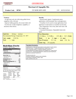

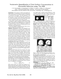
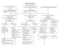
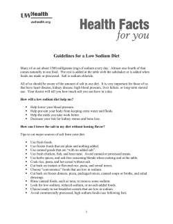


© Copyright 2026