
Simple Method of Changing the Frequency Freescale Semiconductor Application Note
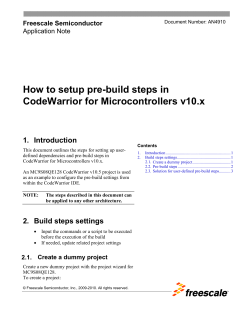
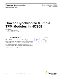
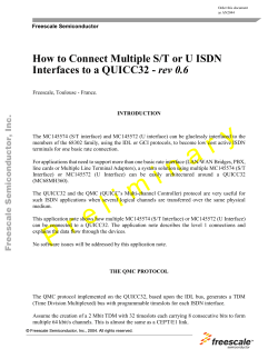
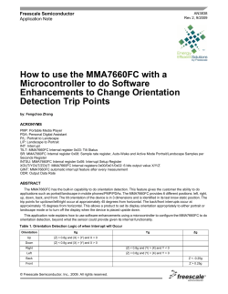
Freescale Semiconductor Application Note AN4859 Rev. 0, 8/2014 Simple Method of Changing the Frequency Range of a Power Amplifier Circuit Amplifier designers often face the challenge of modifying an existing circuit optimized for one frequency range to operate over a different and perhaps wider frequency range, which may be higher or lower in frequency, using the same RF power transistor or transistors. This situation occurs when a manufacturer wants to reduce the number of designs required to cover its product portfolio or to create custom products to meet the needs of a specific application in a short time. When manufacturers meet market requirements with fewer designs, they can reduce cost, complexity, and time to market. Given an unlimited amount of time and budget, the ideal approach would be to create an entirely new design, requiring extensive simulation and a new circuit board, assuming the new frequency range is within the capabilities of the transistor. However, this being a less-than-ideal world, there is often neither the time nor budget available to take this approach. Fortunately, as this application note will show, if the design is single-ended and has no complicated matching sections, it is reasonably easy to extend or shift the bandwidth of the existing circuit design without resorting to extensive resimulation, a new PCB, and many component changes. The approach reduces the time required for the transformation from weeks to as little as one day. 450 to 520 MHz The Challenge This discussion is based on an actual situation that occurred at Freescale when an evaluation board (Figure 1) that was created using Freescale’s 7 W AFT09MS007N Airfast RF power LDMOS transistor to cover a 70 MHz frequency range of 450 to 520 MHz later had to be modified to cover a 120 MHz frequency range of 350 to 470 MHz. The gain, RF output power, and efficiency of the original design were to be maintained. The time available to complete the design did not allow for extensive resimulation or a PCB revision. The AFT09MS007N is an unmatched RF power transistor designed for use in battery-operated, handheld radios that have a supply voltage of about 7.5 Vdc. This transistor can be matched to operate over various sub--bands within its frequency range of 136 to 941 MHz and can deliver more than 7 W RF output power from 200 mW of drive. Broadband circuit efficiency can exceed 70%. The extremely rugged device operates into a VSWR greater than 65:1 at all phase angles without degradation, even when driven at twice its rated drive power and 30% overvoltage. It includes an internal electrostatic discharge protection circuit that protects the MOSFET gate structure from short duration, high--voltage 350 to 470 MHz Figure 1. 7 W AFT09MS007N RF Power LDMOS Transistor Freescale Semiconductor, Inc., 2014. rights reserved. Simple Method ofAllChanging the RF Application Information Freescale Semiconductor, Inc. Frequency Range of a Power Amplifier Circuit, Rev. 0, 08/2014 1 Table 1. 450–520 MHz UHF Broadband Performance (In Freescale Reference Circuit, 50 ohm system) VDD = 7.5 Volts, IDQ = 150 mA, TA = 25C, CW Frequency (MHz) Pin (W) Gps (dB) D (%) Pout (W) 450 0.21 15.4 57.7 7.5 485 0.21 15.5 56.0 7.5 520 0.18 16.2 66.3 7.5 Table 2. 350–470 MHz UHF Broadband Performance (In Freescale Reference Circuit, 50 ohm system) VDD = 7.5 Vdc, IDQ = 200 mA, TA = 25C, CW Frequency (MHz) Pin (W) Gps (dB) D (%) Pout (W) 350 0.15 16.6 60.9 7.3 410 0.15 16.6 66.5 7.3 470 0.20 15.6 70.1 7.3 discharge that may be encountered during assembly. The transistor is housed in an over-molded plastic package. Its key specifications are shown in Table 1. could be used to facilitate the frequency shift. This software is one of many free Smith chart programs available on the web. The transmission line parameter calculator from Clemson University2 was used to estimate the degrees of separation and impedance of the transmission line. Other calculators are also available, including the Freescale Engineering Tools3 app for Android and iPhone, Transmission Line Calc for iPhone from Black Cat Systems, and TX-LINE, a Windowsbased transmission line calculator from AWR4. Getting Started The original 450 to 520 MHz circuit delivered the gain, efficiency, and output power versus a fixed input power of 7.5 V shown in Figure 2. The Iowa Hills Smith Chart program from Iowa Hills Software1 was used to determine if simple Smith chart software rather than comprehensive design software 18 80 70 D 17 60 16 50 Gps 15 10 14 9 Pout 13 12 440 D, DRAIN EFFICIENCY (%) Gps, POWER GAIN (dB) 19 90 VDD = 7.5 Vdc Pin = 0.25 W IDQ = 150 mA 450 460 470 480 490 500 510 520 8 7 530 Pout, OUTPUT POWER (WATTS) 20 f, FREQUENCY (MHz) Figure 2. 450–520 MHz Power Gain, Output Power and Drain Efficiency versus Frequency at a Constant Input Power — 7.5 V Simple Method of Changing the Frequency Range of a Power Amplifier Circuit, Rev. 0, 08/2014 2 RF Application Information Freescale Semiconductor, Inc. VDD = 7.5 Vdc, IDQ = 150 mA, Pout = 7.5 W f = 530 MHz Zsource f = 450 MHz f = 530 MHz Zo = 10 f MHz Zsource Zload 450 0.45 + j2.46 1.56 + j1.05 460 0.40 + j2.37 1.52 + j1.24 470 0.40 + j2.97 1.46 + j1.51 480 0.38 + j3.56 1.39 + j1.71 490 0.41 + j4.16 1.35 + j2.06 500 0.51 + j4.79 1.34 + j2.06 510 0.70 + j5.54 1.37 + j2.30 520 0.93 + j6.44 1.40 + j 2.50 530 1.14 + j7.56 1.42 + j2.62 Zsource = Test circuit impedance as measured from gate to ground. Zload Zload f = 450 MHz 50 = Test circuit impedance as measured from drain to ground. Input Matching Network Output Matching Network Device Under Test Zsource 50 Zload Figure 3. UHF Broadband Series Equivalent Source and Load Impedance — 450–520 MHz First, experimental tuning was employed to shift the frequency directly from the test bench. The tuning was based on tuning tips written when the 450 to 520 MHz design was completed. This allowed the achievement of a 70 MHz bandwidth from 400 to 470 MHz. More tuning resulted in a bandwidth of 85 MHz from 380 to 465 MHz, but the desired 120 MHz bandwidth from 350 to 470 MHz remained elusive. At this point it appeared that only a redesign could solve the problem, but as this would have required significantly more time, including the time required to obtain materials, a different approach was selected. The Solution To meet the challenge, the current PCB, its microstrip transmission lines, and the position of the lumped element were retained to save time and cost. The transmission line impedances were calculated in the transmission line program based on the material properties of the board. Shunt capacitors and series inductors used in the original design were maintained and their values optimized. An adjustment of the transmission line characteristics between these lumped components would have required a PCB revision. The Iowa Hills Smith Chart program uses a combination of fixed and optimized values to achieve the desired impedance transformation. The starting position in a 50 ohm system at the RF input or output is assumed to be 50 + j0 ohms, so the Z0 of the Smith chart is then 50 ohms. For the AFT09MS007N, the gate and drain impedances were each expected to be around 2 to 3 ohms based on interpolation between known narrowband impedances at 136 MHz and broadband impedance from 450 to 520 MHz (the bandwidth of the original circuit). The impedance of LDMOS transistors typically increases as frequency decreases because the reactive part of the impedance is more capacitive, causing the impedance to be inversely proportional to frequency. The capacitive reactance XC = 1/(2 f0 C). As can be seen from the Smith chart (Figure 4), the transformation plot follows a tighter Q circle than the actual measurements portray, because here ideal components and approximations are used. In the future, the circuit could be designed for a tighter Q circle with the knowledge that bandwidth could be maintained in the physical circuit with limitations on accuracy. The impedance was transformed with three matching sections of shunt capacitor plus series inductor following a reasonable Q circle across the Smith chart. The Q was determined via the classic method, Q = center frequency/ bandwidth. Simple Method of Changing the Frequency Range of a Power Amplifier Circuit, Rev. 0, 08/2014 RF Application Information Freescale Semiconductor, Inc. 3 Figure 4. Smith Chart1 — 350–470 MHz VDD = 7.5 Vdc, IDQ = 200 mA, Pout = 7.3 W f = 470 MHz Zo = 10 Zsource f = 350 MHz f = 470 MHz f = 350 MHz f MHz Zsource Zload 350 2.7 + j6.6 3.5 + j4.2 370 3.3 + j6.2 3.7 + j4.2 390 3.1 + j5.4 3.5 + j4.0 410 2.6 + j6.1 3.5 + j5.0 430 2.1 + j7.1 3.6 + j5.9 450 2.2 + j7.3 3.6 + j5.6 470 2.0 + j7.7 3.0 + j5.8 Zsource = Test circuit impedance as measured from gate to ground. Zload Zload 50 = Test circuit impedance as measured from drain to ground. Input Matching Network Output Matching Network Device Under Test Zsource 50 Zload Figure 5. UHF Broadband Series Equivalent Source and Load Impedance — 350–470 MHz Simple Method of Changing the Frequency Range of a Power Amplifier Circuit, Rev. 0, 08/2014 4 RF Application Information Freescale Semiconductor, Inc. Optimization The process of optimization in the Smith Chart program consisted of checking multiple frequencies across the band of interest, making sure that the resulting impedances for 350 and 470 MHz were not too distant from each other. (Such impedances are a hallmark of broadband design.) Once the optimal output match was determined in the Smith Chart program, the components were changed, and focus moved to the input-side transformation. The same process was C1 J1 C6 L3 L1 VGG followed: The components on the RF input were modified, and the new circuit design was taken to the test bench. Using a vector network analyzer, S(1,1) was checked, and a few components were adjusted on the input match to improve the input return loss to ensure optimal gain and to center the frequency response. It became obvious from this exercise that the new match was superior to the old one, which was saved for comparison. The new match improved the return loss by twice the value and did so across a wider frequency. It was then time for the large-signal test. C7 C8 C16 C15 C9 C10 VDD C5 L7 C2 L4 R1 C4 C14 Q1 C3 L5 C11 C12 C13 L6 D49947 AFT09MS007N Rev. 2 L2 C17 Figure 6. AFT09MS007NT1 UHF Broadband Reference Circuit Component Layout — 450–520 MHz Table 3. AFT09MS007NT1 UHF Broadband Reference Circuit Component Designations and Values — 450–520 MHz Part Description Part Number Manufacturer C1, C16 100 pF Chip Capacitors ATC600F101JT250XT ATC C2 7.5 pF Chip Capacitor GQM2195C2E7R5BB12D Murata C3 5.6 pF Chip Capacitor ATC600F5R6BT250XT ATC C4 39 pF Chip Capacitor ATC600F390JT250XT ATC C5, C9 240 pF Chip Capacitors ATC600F241JT250XT ATC C6, C7 0.1 F Chip Capacitors GRM21BR71H104KA01B Murata C8 0.01 F Chip Capacitor GRM21BR72A103KA01B Murata C10 2.2 F Chip Capacitor GRM31CR71H225KA88L Murata C11, 12 12 pF Chip Capacitors ATC600F120JT250XT ATC C13 8.2 pF Chip Capacitor ATC600F8R2BT250XT ATC C14 20 pF Chip Capacitor ATC600F200JT250XT ATC C15 2 pF Chip Capacitor ATC600F2R0BT250XT ATC C17 47 pF Chip Capacitor ATC600F470JT250XT ATC J1 3--pin Header 22-28-8360 Molex L1 2.55 nH Inductor 0906-3JLC Coilcraft L2 3.85 nH Inductor 0906-4JLC Coilcraft L3 22 nH Inductor 0908SQ22N Coilcraft L4, L5 17 nH Inductors 0908SQ17N Coilcraft L6 1.65 nH Inductor 0906-2JLC Coilcraft L7 8.1 nH Inductor 0908SQ8R1N Coilcraft R1 22 , 1/10 W Chip Resistor RR1220Q-220-D Susumu Q1 RF Power LDMOS Transistor AFT09MS007NT1 Freescale PCB Shengyi S1000-2, 0.020, r = 4.8 D49947 MTL Simple Method of Changing the Frequency Range of a Power Amplifier Circuit, Rev. 0, 08/2014 RF Application Information Freescale Semiconductor, Inc. 5 Initial efficiency was low, but the desired output power was achieved across the entire 120 MHz bandwidth and actually extended to 300 MHz. After about a half hour of tuning, the bandwidth was tightened to the 350 to 470 MHz specification, J1 C1 C15 C14 C19 C9 C2 L3 C13 C18 C12 L1 L7 C10 C4 C11 C5 L4 R1 L2 C17 L5 L6 C16 Q1 C8 C6 C7 Rev. 1 C3 the efficiency met the required minimum of at least 60%, gain was reasonably flat, and output power with a fixed input power of 250 mW was at least 7 W. The desired performance was obtained in less than one day of redesign and testing. D58008 Figure 7. AFT09MS007NT1 UHF Broadband Reference Circuit Component Layout — 350–470 MHz Table 4. AFT09MS007NT1 UHF Broadband Reference Circuit Component Designations and Values — 350–470 MHz Part Description Part Number Manufacturer C1, C10, C19 100 pF Chip Capacitors ATC600F101JT250XT ATC C2 10 pF Chip Capacitor ATC600F100JT250XT ATC C3 3.0 pF Chip Capacitor ATC600F3R0BT250XT ATC C4, C8 27 pF Chip Capacitors ATC600F270JT250XT ATC C5 5.1 pF Chip Capacitor ATC600F5R1BT250XT ATC C6, C7 30 pF Chip Capacitors ATC600F300JT250XT ATC C9 10 nF Chip Capacitor C1210C103J5GAC-TU Kemet C11 82 pF Chip Capacitor ATC600F820JT250XT ATC C12 240 pF Chip Capacitor ATC600F241JT250XT ATC C13 2.2 F Chip Capacitor C3225X7R1H225K250AB TDK C14 0.1 F Chip Capacitor GRM21BR71H104KA01B Murata C15 0.01 F Chip Capacitor GRM21BR72A103KA01B Murata C16 47 pF Chip Capacitor ATC600F470JT250XT ATC C17 18 pF Chip Capacitor ATC600F180BT250XT ATC C18 7.5 pF Chip Capacitor ATC100A7R5JT150XT ATC J1 3--pin Header 22-28-8360 Molex L1 8.1 nH Inductor 0908SQ8N1 Coilcraft L2 2.55 nH, 3 Turn Inductor 0906-3JLC Coilcraft L3, L4, L5 21.5 nH Inductors 0908SQ22N Coilcraft L6 3.85 nH, 4 Turn Inductor 0906-4JLC Coilcraft L7 8.9 nH Inductor 0806SQ8N9 Coilcraft Q1 RF Power LDMOS Transistor AFT09MS007NT1 Freescale R1 62 , 1/10 W Chip Resistor RG2012N-620-B-T1 Susumu PCB Shengyi S1000-2, 0.020, r = 4.8 D58008 MTL Simple Method of Changing the Frequency Range of a Power Amplifier Circuit, Rev. 0, 08/2014 6 RF Application Information Freescale Semiconductor, Inc. 18 80 D 17 60 16 Gps 15 14 Pout 13 12 320 70 340 360 380 400 420 440 460 480 D, DRAIN EFFICIENCY (%) Gps, POWER GAIN (dB) 19 90 VDD = 7.5 Vdc Pin = 0.20 W IDQ = 200 mA 50 8 7 6 Pout, OUTPUT POWER (WATTS) 20 5 500 f, FREQUENCY (MHz) Figure 8. 350–470 Power Gain, Drain Efficiency and Output Power versus Frequency at a Constant Input Power The previous board required 25 passive components (19 unique values), and the new board requires 27 (with 21 unique values). The total cost of increasing the bandwidth from 70 to 120 MHz was negligible. The component layout and values of the circuit are shown in Figure 7, and the gain, RF output and efficiency of the final circuit are shown in Figure 8. Summary When faced with extending the bandwidth and the possibility of shifting the operating frequency range of an existing circuit, logic dictates that significant additional simulation, a new PCB, and additional components all will be required. However, this is not always necessary or even possible within given time and cost constraints. The process described in this application note was achieved using only Smith chart and transmission line calculation software, demonstrating that experimental tuning and review with a Smith chart can avoid the possibility of creating an untenable design. The approach can be applied to other RF power outputs, frequency range conversions, and bandwidth extensions, but it is important to remember the following: When converting from a low-power design to a high-power design, any new components, the PCB, and the microstrip line must be able to handle the increased power. It is possible to change the frequency range when the original range is reasonably close to the one desired. However, if the original design was centered on 20 MHz (for example) and the new frequency range is centered on 500 MHz, the conversion probably would not be achievable. If the conversion is to a lower frequency, transmission line widths can probably remain the same as in the original design, but component values get larger. Additional Reading Chris Bowick, RF Design, 2nd Edition, 2008, pp. 69–102 (for Q and Smith chart impedance matching). David M. Pozar, Microwave Engineering, 3rd Edition, 2005, p. 272, Table 6.1 (for common equations used in RF circuit design). Sources of Smith Chart and Transmission Line Tools 1. Iowa Hills Software (Smith chart program), http://www.iowahills.com/9SmithChartPage.html 2. Clemson University transmission line parameter calculator, http://www.cvel.clemson.edu/Emc /calculators/TL_Calculator/ 3. Freescale RF Engineering Tools App V1.0 (Transmission line calculator and other features), http://www.freescale.com/RFENGTOOLS 4. AWR Corp. TX-LINE (Transmission line calculator), http://www.awrcorp.com/products/optional-products /tx-line-transmission-line-calculator AFT09MS007N Documentation and Tools http://freescale.com/AFT09MS007N If the conversion is to a higher frequency, component values get smaller, but transmission lines may have to be widened to reach the desired impedance. Simple Method of Changing the Frequency Range of a Power Amplifier Circuit, Rev. 0, 08/2014 RF Application Information Freescale Semiconductor, Inc. 7 How to Reach Us: Home Page: freescale.com Web Support: freescale.com/support Information in this document is provided solely to enable system and software implementers to use Freescale products. There are no express or implied copyright licenses granted hereunder to design or fabricate any integrated circuits based on the information in this document. Freescale reserves the right to make changes without further notice to any products herein. Freescale makes no warranty, representation, or guarantee regarding the suitability of its products for any particular purpose, nor does Freescale assume any liability arising out of the application or use of any product or circuit, and specifically disclaims any and all liability, including without limitation consequential or incidental damages. “Typical” parameters that may be provided in Freescale data sheets and/or specifications can and do vary in different applications, and actual performance may vary over time. All operating parameters, including “typicals,” must be validated for each customer application by customer’s technical experts. Freescale does not convey any license under its patent rights nor the rights of others. Freescale sells products pursuant to standard terms and conditions of sale, which can be found at the following address: freescale.com/SalesTermsandConditions. Freescale and the Freescale logo are trademarks of Freescale Semiconductor, Inc., Reg. U.S. Pat. & Tm. Off. Airfast is a trademark of Freescale Semiconductor, Inc. All other product or service names are the property of their respective owners. E 2014 Freescale Semiconductor, Inc. Simple Method of Changing the Frequency Range of a Power Amplifier Circuit, Rev. 0, 08/2014 AN4859 8Rev. 0, 8/2014 RF Application Information Freescale Semiconductor, Inc.


© Copyright 2026