
How to Implement a Human Machine Interface Using the 1
Freescale Semiconductor
Application Note
Document Number: AN3934
Rev. 0, 10/2009
How to Implement a Human
Machine Interface Using the
Touch Sensing Software Library
1
Introduction
This application note shows you, how in fourteen steps,
to write your first touch sensing application (“from
scratch”) using the Touch Sensing Software (TSS)
Library. After configuring, touching a sensor turns on a
LED. In addition, you will be able to turn on a virtual
LED from within the CodeWarrior debugger.
There are two “Extra Credit” sections. The first, shows
you how to add a second sensor and LED. The second,
shows you how to view, touch, and release events in the
CodeWarrior Debugger.
Although this application note uses the Freescale
TSSEVB, the same procedure can be used to create touch
controls using virtually any Freescale 8-bit MCU.
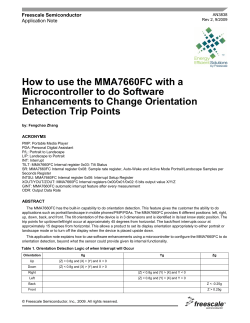
The hardware used is the Freescale TSS evaluation board
(TSSEVB). The touch pad used is assigned as shown in
Figure 1. The LED associated with the touch sensor is
also shown.
© Freescale Semiconductor, Inc., 2007. All rights reserved.
Contents
1
2
3
Introduction . . . . . . . . . . . . . . . . . . . . . . . . . . . . . . . . . . . 1
Background Information . . . . . . . . . . . . . . . . . . . . . . . . . 3
Part 1—Writing the Code. . . . . . . . . . . . . . . . . . . . . . . . . 4
3.1 Step 1—Create the Project Using the Wizard . . . . . 4
3.2 Step 2—Adding the Library Files to the Project. . . . 6
3.3 Step 3—Create the System Setup Module . . . . . . . 7
3.4 Step 4—Set the Interrupt Vector (IRQ) . . . . . . . . . 10
3.5 Step 5—Adding the MCU Initialization to main.c. . 11
3.6 Step 6—Add the TSS Initialize Function to main() 12
3.7 Step 7—Add the TSS Task Function to main() . . . 13
3.8 Step 8—Set the Electrode Sensitivity and Enable. 13
3.9 Step 9—Configure the Keypad Decoder . . . . . . . . 14
3.10 Step 10—Add the Callback Function. . . . . . . . . . . 15
3.11 Step 11—Bind the Control to the Blue LED. . . . . . 17
4
Part II—Debugging and Testing . . . . . . . . . . . . . . . . . . 17
4.1 Step 12—Download and Run the Program . . . . . . 17
4.2 Step 13—Inserting a Breakpoint and Viewing . . . . 19
4.3 Step 14—Adding a Visualization Tool . . . . . . . . . . 21
5
Part III—Extra Credit . . . . . . . . . . . . . . . . . . . . . . . . . . . 25
6
Part IV — Extra-Extra Credit . . . . . . . . . . . . . . . . . . . . . 29
Appendix Amain.c Program Listing . . . . . . . . . . . . . . . . . . . . 32
Introduction
Blue LED— Lights up
when a touch sensor
is touched
Touch sensor
Figure 1. TSSEVB
Learn how to also use the debugger visualization tool in the CodeWarrior debugger containing three
objects. One is a LED object that changes from green to blue when the electrode is touched. The other two
objects display the value of the capacitance using a bar, graph and text.
Figure 2. Debugger VisualizationTool
NOTE
The LCD display is not used in this application note. The demo software
included with the TSSEVB has an LCD driver support. After you
understand the TSS basics, you should be able to bind touch events to the
LCD display.
The TSS library has many enhanced features including:
• Configurable number of electrodes from 1 to 64
• Configurable number of keypads, rotaries, and sliders
• Configurable electrode sensitivity
• False detection prevention against external environment
• Electrode fault detection
• Use of any standard MCU I/O as an electrode
• Only one MCU timer is used
How to Implement a Human Machine Interface Using the Touch Sensing Software Library, Rev. 0
2
Freescale Semiconductor
Background Information
2
Background Information
To take full advantage of the application note, you need CodeWarrior Version 6.2 (or later). With Version
6.2, you must install the 6.2.2 patch. This patch is needed to support the Freescale open source background
debugger (OSBDM). Make sure to install the latest CodeWarrior patch for the HC9S08SG32, the TSS
library and the code generation tool; System Setup GUI.
The TSS library documentation can be found on the Freescale website. This includes the TSS API
reference manual (TSSAPIRM) and the TSSEVB user guide (TSSEVBUG). The TSSAPIRM details the
data structures, control registers, status registers, and macros used. It also contains appendices that discuss
the details of the touch sensing algorithms.
If you have another Freescale evaluation board, it is necessary to create touch electrodes. This can be as
simple as a wire connected from an available GPIO pin to a small copper pad (for example 1 cm x 1 cm)
with a 1 mega-ohm resistor connected to the pad and to the Vcc. Figure 3 is a crude but working four
electrode configuration mounted on a cardboard and connected to an MC9S08QG8 demo board.
Figure 3. Four electrode configuration mounted on cardboard
You can also order a touch pad kit; part number KITPROXIMITYEVM. This kit connects to several
Freescale MCU demo and evaluation boards.
Figure 4. Touch pad kit—(KITPROXIMITYEVM)
How to Implement a Human Machine Interface Using the Touch Sensing Software Library, Rev. 0
Freescale Semiconductor
3
Part 1—Writing the Code
3
Part 1—Writing the Code
3.1
Step 1—Create the Project Using the Wizard
1. The first thing to do is to create a project in CodeWarrior using the project wizard. To start the
wizard, click File > New Project.
This brings up the following window, Figure 5.
2. Highlight, Microcontrollers New Project Wizard. Then enter the name of your project. In this case,
“My_Touch” was used.
3. Click the Set button to locate the project on your disk. This creates a folder called “My_Touch” on
your hard drive where the project is now located.
Click OK when finished.
Figure 5. New project window
4. In Figure 6 select the MC9S08LG32 from the derivative list. This sets up the project to load in the
proper headers and the initialization files needed by the compiler. (If using another processor, select
that one instead). Highlight the HCS08 Open Source BDM for the debugger connection.
Click Next to finish.
Figure 6. Microcontroller New Project window—derivative list
How to Implement a Human Machine Interface Using the Touch Sensing Software Library, Rev. 0
4
Freescale Semiconductor
Part 1—Writing the Code
5. Next, Figure 7. Make certain that the language support is C as shown.
Click Finish when you are ready. This starts the project build process.
Figure 7. Microcontrollers New Project window—language support
6. After a few moments, the screen appears as shown in Figure 8. The red check marks indicate that
the project has not been compiled. Go ahead and build the project by pressing F7, click the Make
icon
or Project > Make. You should receive no errors and warnings. The red check marks must
disappear. The program does not do anything useful, but you can examine main.c by
double-clicking file name.
Figure 8. Freescale CodeWarrior window
How to Implement a Human Machine Interface Using the Touch Sensing Software Library, Rev. 0
Freescale Semiconductor
5
Part 1—Writing the Code
3.2
Step 2—Adding the Library Files to the Project
CodeWarrior allows for many different ways to add files to projects. You can add them one at a time using
Project > Add Files, or drag them into the project window.
1. First, create a new group folder to hold the TSS files. Click Project > Create Group and name it
TSS. This places a new group folder at the top of the list as shown in Figure 9.
New group
Figure 9. New group folder window
2. Locate the library files that were installed when the TSS was installed. The default location is:
C:\Program Files\Freescale\Freescale TSS x.x\lib
It may be different, depending upon the directory you indicated during the installation. The “x.x”
is the version number.
3. Using Windows Explorer, highlight all 14 files in this directory and drag them into the TSS group.
Notice the cursor appears below the TSS folder. The result looks similar to Figure 10. There must
be at least 14 files added to the TSS group. A description of each file is found in the TSSAPI
reference manual.
Figure 10. Directory
NOTE
Not all the files are required for this particular application note. Unused files
are simply not compiled and linked.
How to Implement a Human Machine Interface Using the Touch Sensing Software Library, Rev. 0
6
Freescale Semiconductor
Part 1—Writing the Code
3.3
Step 3—Create the System Setup Module
The system setup module is found in the low level interface and is configured in the TSS_SystemSetup.h
file. This module needs to be created.
The module contains several parameters including:
•
•
•
•
•
•
•
•
•
•
•
•
Capacitive sensing method
Drive strength
Slew rate
Number of electrodes
Port and pin for each electrode
Number of controls
Control type
Number of electrodes per control
Structure name
Callback function name
MCU timer module
Instant delta values
This can be a large and tedious file to create, especially if there are many electrodes and controls.
Freescale provides a code builder program that does this automatically. This program is called the System
Setup GUI. This is a program that was installed on your PC when the TSS libraries were installed. The
default program location is:
Start>Programs>Freescale>Touch Sensing Software vx.x>System Setup GUI
When the program is launched, there are several options available. For this application note, one electrode,
one control, TPM1, and the ATL sensing algorithm are used.
1. In Figure 11 check the delta log array box. This creates a data array that contains the capacitance
sensing value minus the baseline value that is calculated when the TSS is initialized. This value is
used in the Debugger Visualization bar-graph control later on.
2. Next, define the GPIO pin assigned to the electrode E0. Check the box in the circle to bring up
another window. See Figure 12.
How to Implement a Human Machine Interface Using the Touch Sensing Software Library, Rev. 0
Freescale Semiconductor
7
Part 1—Writing the Code
Delta log array box
Define the GPIO
pin assigned to the
E0
Figure 11. System Setup Creator
3. In Figure 12 looking at the TSSEVB schematic, notice that the electrode to activate is connected
to Port A, bit 2. Set the values accordingly.
Figure 12. Electrode 0—TSSEVB schematic
At this point, a single electrode has been created, a single control, and the electrode assigned to the GPIO
bit 2 on PortA, using the timer peripheral #1 (TPM1).
4. The last step is to define the control properties. Accomplish this by clicking the Control icon:
. This brings up the following window. See Figure 13.
In this window you can examine and edit:
— The Control Type (Keypad, Slider, or Rotary)
— The Number of Electrodes in the Control
— The Structure Name
— The CallBack Name
For this example, use the defaults.
Click OK button.
How to Implement a Human Machine Interface Using the Touch Sensing Software Library, Rev. 0
8
Freescale Semiconductor
Part 1—Writing the Code
Figure 13. Control 0—Control Properties
5. The electrodes, GPIO pins, and the controls are defined. The code is ready to be generated. Click
Generate Code. Save it in the “My_Touch” folder. It is automatically named TSS_SystemSetup.h
file.
6. The system module file has now been generated, it is time to add it to the CodeWarrior project. As
before mentioned, drag the file TSS_SystemSetup.h file into the TSS group, or click Project >
Add Files.
7. After this is finished, the TSS_SystemSetup.h appears in the project window. Double-click to view
its contents in the right panel as shown in Figure 14.
Figure 14. Freescale CodeWarrior—TSS_SystemSetup.h
Tip—Right-click any file and select “Open in Windows Explorer”. You can then see where the files are
located. Notice that when you dragged them into this project, only the links were placed. The library files
remain in their initial location.
How to Implement a Human Machine Interface Using the Touch Sensing Software Library, Rev. 0
Freescale Semiconductor
9
Part 1—Writing the Code
3.4
Step 4—Set the Interrupt Vector (IRQ)
In the previous Section 3.3, “Step 3—Create the System Setup Module,” TPM1 was defined as the timer
used to measure capacitance. When this timer overflows, an interrupt is generated and is serviced by the
TSS library. Each IRQ is assigned a number starting at 0, the reset vector. If you examine the
MC9S08LG32 reference manual MC9S08LG32RM, the vector number of TPM1 overflow is assigned as
Vector 6.
1. To add this vector to the project, open the prm file located in Project Settings > Linker Files
group. Double-click the Project.prm file.
Figure 15. Project.prm file
2. At the end of the file, the timer overflow vector definition must be added:
VECTOR 6 ATL_TimerIsr
ATL_TimerISR
is defined in ATL_Timer.h.
The last two lines of Project.prm must look as Figure 16:
Figure 16. Project.prm—Vector definitions
3.5
Step 5—Adding the MCU Initialization to main.c
In this step, add a function called MCU_Init(). This function initializes the MC9S08LG32 clocks and
other peripherals. If another MCU is used other than the MC9S08LG32, the code may have to be modified
accordingly. Please refer to the appropriate reference manual.
Tip—The Device Initialization feature of the Processor Expert can be used to create an MCU_Init
function.
1. Add the MCU_Init function to main.c
How to Implement a Human Machine Interface Using the Touch Sensing Software Library, Rev. 0
10
Freescale Semiconductor
Part 1—Writing the Code
Figure 17. main.c—MCU_Init function
3.5.1
Step 5—Add TSS_API.h to the project
The TSS_API.h contains all definitions and data types needed to access the TSS library.
1. Add the following line at the beginning of main.c
#include "TSS_API.h"
main.c must now look like Figure 18.
How to Implement a Human Machine Interface Using the Touch Sensing Software Library, Rev. 0
Freescale Semiconductor
11
Part 1—Writing the Code
Figure 18. main.c
3.6
Step 6—Add the TSS Initialize Function to main()
The TSS_Init function initializes all the data structures of the library and all the values needed to start using
it.
1. Add this function after the MCU_Init. It is important to have the MCU clock configured before
calling the TSS_Init function.
UINT8TSS_Init(void)
Input parameters:
None
Returns:
STATUS_OK
Figure 19. TSS_Init
How to Implement a Human Machine Interface Using the Touch Sensing Software Library, Rev. 0
12
Freescale Semiconductor
Part 1—Writing the Code
3.7
Step 7—Add the TSS Task Function to main()
The TSS_Task function performs all the tasks related to the TSS. The task function must be called
periodically to keep sensing the electrodes.
In Figure 20, the function is called in the main loop.
void TSS_Task(void)
Input parameters:
None
Returns:
None
Figure 20. TSS_Task
3.8
Step 8—Set the Electrode Sensitivity and Enable the Library
Here, the electrode sensitivity threshold is set to a value of 32 counts (0 x 20). This is executed by calling
TSS_SetSystemConfig function. Add the two lines indicated in Figure 21.
Figure 21. TSS_SetSystemConfig function
How to Implement a Human Machine Interface Using the Touch Sensing Software Library, Rev. 0
Freescale Semiconductor
13
Part 1—Writing the Code
NOTE
You can only set electrode sensitivities via this function. The value can not
be set directly. It is useful to adjust sensitivities for each electrode. They will
differ depending on the size of the electrode, PCB routing, the size of the
pull up resistor, and the thickness, and dielectric constant of the overlay
material.
If more than one electrode is defined, the second parameter would be:
System_Sensitivity_Register+n
Where n is an offset value. If it is not included, it assumes a value of zero and points to the first electrode.
The system configuration register has the following prototype:
UINT8 TSS_SetSystemConfig(UINT8 u8Parameter, UINT8 u8Value)
Input parameters:
u8Parameter—Code indicating the register value to access, such as System_Sensitivity_Register,
or the System_SystemConfig_Register. These are defined in TSS_API.h.
u8Value—The new desired value for the respective configuration register, such as a sensitivity
value, or a bit mask (for example: TSS_SYSTEM_EN_MASK). Bit mask definitions are
TSS_API.h
Returns:
STATUS_OK
ERROR_CONFSYS_OUT_OF_RANGE
ERROR_CONFSYS_READ_ONLY_PARAMETER
ERROR_CONFSYS_ILEGAL_PARAMETER
Hint—You can find out where each function or bit-mask is defined by right-clicking the name and select
Go to the macro declaration.
3.9
Step 9—Configure the Keypad Decoder
This step configures the TSS Keypad Decoder. The TSS creates a structure that contains the status and
control value of the decoder. Examples include the auto-repeat rate, maximum number of touches, the
buffer location, and others. These are explained in more detail in the TSS API reference manual.
Two lines of code will be added using the TSS function TSS_KeypadConfig.
(void)TSS_KeypadConfig(cKey0.ControlId,Keypad_Events_Register,
TSS_KEYPAD_TOUCH_EVENT_EN_MASK);
(void)TSS_KeypadConfig(cKey0.ControlId,Keypad_ControlConfig_Register,
TSS_KEYPAD_CONTROL_EN_MASK|TSS_KEYPAD_CALLBACK_EN_MASK);
Notice that the first parameter passes the ControlId element of the cKey0 structure using standard C
methods to access an element in a data structure. Pay attention to the dot.
1. Add the following two lines as indicated in Figure 22.
How to Implement a Human Machine Interface Using the Touch Sensing Software Library, Rev. 0
14
Freescale Semiconductor
Part 1—Writing the Code
Figure 22. TSS_KeypadConfig
The TSS_KeypadConfig function has the following prototype:
UINT8 TSS_KeypadConfig(CONTROL_ID u8CtrlId, UINT8 u8Parameter, UINT8 u8Value)
Input parameters:
u8CtrlId—Identifier of the control to be configured (an element in a data structure). It is defined
in TSS_API.h
u8Parameter—Code indicating the register value to be configured.
u8Value—The new desired value.
Returns:
STATUS_OK
ERROR_KEYPAD_ILEGAL_CONTROL_TYPE
ERROR_KEYPAD_READ_ONLY_PARAMETER
ERROR_KEYPAD_OUT_OF_RANGE
ERROR_KEYPAD_ILEGAL_PARAMETER
ERROR_KEYPAD_NOT_IDLE
3.10
Step 10—Add the Callback Function
In this step, the callback function was added to main.c. This function was defined by the GUI tool in
Section 3.3, “Step 3—Create the System Setup Module,” on page 7, and the default name fCallBack0 is
used.
How to Implement a Human Machine Interface Using the Touch Sensing Software Library, Rev. 0
Freescale Semiconductor
15
Part 1—Writing the Code
The callback function is used by the TSS to let the user know that an event in the electrodes status has
occurred.
The event that triggers the callback function can be configured by the user depending on the application
and the decoder type used. For example, you can have a callback when an electrode is touched or released.
Callback functions are assigned to controls in the TSS System Setup module, and one callback may be
assigned to different controls in the system. In this example, FCallBack0 was dfined to be a keyboard
module.
1. Add the following lines of code in main.c.
Figure 23. FCallBack0
Hint—If you declare u8Key as static, the value can be viewed in the Debugger.
The function prototype for a callback function is:
void CallbackFuncName(UINT8 u8ControlId)
Input parameters:
ControlId—Because
the same callback function can be assigned to more than on controller,
ControlId indicates the control that generated the event. This parameter matches the ControlId field
in the control structure.
Returns:
None
The TSS library contains many macros that ease the programming task. The two macros used in the
callback function are TSS_KEYPAD_BUFFER_EMPTY and TSS_KEYPAD_BUFFER_READ.
The buffer read macro, TSS_KEYPAD_BUFFER_READ, reads the first event element from the buffer
and automatically updates the buffer read index register.
TSS_KEYPAD_BUFFER_READ(destvar,kpcsStruct)
Input Parameters:
destvar—Name of the variable where the first unread element will be stored. The most significant
bit of this variable indicates if the event was a touch or a release (1 touch and 0 release). The lower
six bits indicate the electrode number that reported the event.
kpcsStruct—The name of the structure assigned by the user in the SystemSetup.h file.
Returns:
None
How to Implement a Human Machine Interface Using the Touch Sensing Software Library, Rev. 0
16
Freescale Semiconductor
Part 1—Writing the Code
The TSS also features a macro that allows the user to know when the buffer event is empty. The macro
performs a comparison between the Buffer Read Index and the Buffer Write Index.
TSS_KEYPAD_BUFFER_EMPTY(kpcsStruct)
Input Parameters:
kpcsStruct—The
name of the structure assigned by the user in the SystemSetup.h file.
Returns:
The macro performs a comparison between the first unread element in the buffer and the first free
element. When the two indexes are equal, it means that all the elements in the buffer have been
read. When the macro is called, it verifies if all the elements have been read and returns “1”. If not,
it returns “0”.
3.11
Step 11—Bind the Control to the Blue LED
This is the last step before compiling and running the project.
1. There are four blue LEDs on the top side of the TSSEVB. This example uses D1. It is connected
to GPIO Port F pin 7. Make it an output by placing the code following MCU_Init as shown:
Figure 24. MCU_Init—output
Persistent status of the touch panels are contained in a buffer called tss_au8ElectrodeStatus[n] where n is
the control number. The lower 6 bits contain the electrode that was touched, starting from 1 to 63. Because
there is only one electrode, check to see if it has a value of 0 x 01;
2. Add the following two lines inside the main loop after calling TSS_Task as shown:
Figure 25. TSS_Task
You are now ready to compile the code. Press F7 to compile, or use Project > Make from the pull-down
menu. You can also click the Make icon
in the project window.
You should see one warning and no errors. If you get errors, recheck your code.
NOTE
A complete listing of main.c is shown in Appendix A, “main.c Program
Listing”.
How to Implement a Human Machine Interface Using the Touch Sensing Software Library, Rev. 0
Freescale Semiconductor
17
Part II—Debugging and Testing
4
Part II—Debugging and Testing
4.1
Step 12—Download and Run the Program
Time to download and run the code; assuming you were able to compile without errors in the previous step.
Make sure that J8-OSBDM on the TSSEVB is connected to your PC using the USB cable. This connects
the open source background debugger module (OSBDM) to the debugger. The OSBDM is a separate
Freescale HC9S08JM60 MCU mounted underneath the PCB.
NOTE
The first time the USB cables connected to your PC, Microsoft Windows
starts a wizard to load in the proper USB driver.
Make certain that a jumper is connected between pins 1 and 2 of J4 (USB POWER SEL). This provides
power from the USB to the TSSEVB.
1. From inside CodeWarrior, launch the debugger. This can be executed a couple of ways: Press the
F5 key, or click the Debug Icon
.
2. A Loader Warning pops up.
Click OK button.
Figure 26. Loader Warning
The program is loaded in the flash and the following screen appears, Figure 27.
1. The program has halted at the first line of main().
2. To run the program press F5, Run > Start/Continue, or click
How to Implement a Human Machine Interface Using the Touch Sensing Software Library, Rev. 0
18
Freescale Semiconductor
Part II—Debugging and Testing
Figure 27. True Time Simulator and Real Time Debugger
3. The program must now be running. This is indicated by the message on the bottom left side of the
screen as shown in Figure 28:
Figure 28. Running screen
4. Try touching the pad. If the LED D1 lights up then you have succeeded.
4.2
Step 13—Inserting a Breakpoint and Viewing Variables
1. Halt the program by pressing F6 or clicking
.
Chances are, the program halts in a random area of the program. Load the main.c source code back
into the Source Window.
2. Place the cursor inside this window and right-click. Then click Open Source File.
3. The following lists all the source windows you can load. Select main.c and click OK.
How to Implement a Human Machine Interface Using the Touch Sensing Software Library, Rev. 0
Freescale Semiconductor
19
Part II—Debugging and Testing
Figure 29. Source Files
Alternatively, you can double-click main() in the Procedure window as shown below:
Figure 30. Procedure window
4. With main.c shown in the Source window, scroll down main loop. Place the mouse cursor
somewhere in the middle of the line PTFD_PTFD7=0;. Right-click and select Set Breakpoint. A
small red arrow must appear.
Figure 31. Source window
5. Start the program by pressing F5 or clicking the Run icon
. When you touch the pad, the
program breaks. You can now single step through each line by pressing F10 or clicking the Step
Over icon.
How to Implement a Human Machine Interface Using the Touch Sensing Software Library, Rev. 0
20
Freescale Semiconductor
Part II—Debugging and Testing
6. In the Data:1 window, scroll down and expand the variable tss_au8ElectrodeStatus. Notice
that, it is defined as an array of length one. Click “+” to expand the tree. It contains a value of 1,
meaning that the electrode was touched. This variable is used in the next step.
Figure 32. Data:1 window
7. Add a new variable to the Data:2 window. Right-click in the window and select Add Expression.
Enter the variable tss_ai8InstantDelta. This is the measured capacitance value. There is a
difference (delta) between the baseline (untouched) value and the measured value.
8. Click the “+” to see the value. In this case, it is 127. This value is used later on. It may be different
depending upon how hard you touch the pad. A very light touch would give a lower result. Notice
that the program does not halt until the delta value is above 0 x 20 which you set with the line of
code:
(void)TSS_SetSystemConfig(System_Sensitivity_Register,0x20)
Figure 33. Data:2 window
4.3
Step 14—Adding a Visualization Tool
The CodeWarrior tool kit has powerful features, including a visualization tool. Use this to create widgets
that display and modify the program memory.
1. Click Component>Open.
2. The following window appears (Figure 34). Scroll down until you see the VisualizatoinTool icon.
Highlight it and click the OK button.
How to Implement a Human Machine Interface Using the Touch Sensing Software Library, Rev. 0
Freescale Semiconductor
21
Part II—Debugging and Testing
Figure 34. Open Window Component—Visualizationtool
3. Place the cursor somewhere in the middle of the screen and right-click. Select Add New
Instrument >LED. See Figure 35.
Figure 35. VisualizationTool
4. Place the LED in the upper left side of the screen. Use the drag bars around the LED to increase
the size. Reduce the size of the screen to for a better look. You must now have a window that looks
like Figure 36.
How to Implement a Human Machine Interface Using the Touch Sensing Software Library, Rev. 0
22
Freescale Semiconductor
Part II—Debugging and Testing
Figure 36. VisualizationTool with LED
5. Next, the LED turns on when the touch pad is touched. Double-click the LED. This brings up a
Properties menu. See Figure 37.
6. Set the properties as follows:
— Kind of Port—Choose, Expression
— Port to Display—Enter, tss_au8ElectrodeStatus[0].
— Color if Bit==1—Select blue.
— Press Enter
Figure 37. Properties window
7. Indicate to CodeWarrior how often to update the LED value. Click the Properties Icon
(or
right-click in the window and select Properties). Set Refresh Mode to Periodical. Set Refresh Time
to 1 (every 100 ms).
Close the window.
How to Implement a Human Machine Interface Using the Touch Sensing Software Library, Rev. 0
Freescale Semiconductor
23
Part II—Debugging and Testing
Figure 38. Properties window
8.
It is necessary to remove the break point set earlier in Section 4.2, “Step 13—Inserting a
Breakpoint and Viewing Variables,” on page 19 before trying out. There are a couple of ways to do
this:
— Right-click in the area to the right of the break point icon and select Disable Breakpoint or
Delete Breakpoint
— Right-click in the source window and select Show Breakpoints, then click the Disable button.
9. With the break points disabled, press F5 or click the Run icon. When you touch the pad, the LED
should change its color to blue.
10. Next, add a text value to update the delta value and a bar-graph to show this value visually.
11. Add two more instruments: Value as Text and Bar.
12. Double-click the Bar instrument.
13. For the Bar Properties, enter:
— Kind of Port—Expression
— Port to Display—tss_ai8InstantDelta[0]
Close the window.
14. Double-click the Value as Text instrument.
15. Enter the following properties:
— Kind of Port—Expression
— Port to Display—tss_ai8InstantDelta[0]
Close the window.
How to Implement a Human Machine Interface Using the Touch Sensing Software Library, Rev. 0
24
Freescale Semiconductor
Part III—Extra Credit
Figure 39. Visualization setup
16. Press F5 to run, if it is not already running; see the results in Figure 39. If the EditMode button
is enabled, you can change the colors and fonts as you go along. Try changing the bar color to blue.
17. After you are finished, save your Visualization setup. Otherwise, it erases the next time you run the
debugger. Do this by File > Save Configuration.
NOTE
If the Visualization window disappears, it is probably behind other
windows. You can bring it to focus selecting Window > VisualizationTool.
5
Part III—Extra Credit
In this section, another electrode is added to the Keypad Control. In this case, the LED is located in the
center of a touch pad.
Blue LED light
when touch
sensor is
touched
Touch sensor
Figure 40. TSSEVB
The first thing to do is generate a new TSS_SystemSetup.h header file to add the second touch sensor
properties and to inform TSS of the new configuration. Use the same GUI program as shown in
Section 3.3, “Step 3—Create the System Setup Module,” on page 7.
1. Add an electrode to the Control C0.
— Total Electrodes—2
— Number of Controls—1
How to Implement a Human Machine Interface Using the Touch Sensing Software Library, Rev. 0
Freescale Semiconductor
25
Part III—Extra Credit
— ATL Timer Used—TPM1
— Use Delta Log Array—Checked
Looking at the TSSEVB schematic, the electrode to use is at Port H, bit 6.
2. Click the E1 check box and enter Port—H, Bit—6.
Figure 41. System Setup Creator window
3. Click C0
button.
4. Make sure to set the Number of Electrodes in Control—2.
Click OK button to finish.
Figure 42. Control 0 window
5. Save the new file by clicking Generate Code. Save it to the same location that you stored
TSS_SystemSetup.h file. Click Yes when asked if you want to overwrite the file.
6. When finished, CodeWarrior notices that the file has changed and asks if you want to reload it.
Click Yes.
Examine the new TSS_SystemSetup.h file. Notice the changes.
How to Implement a Human Machine Interface Using the Touch Sensing Software Library, Rev. 0
26
Freescale Semiconductor
Part III—Extra Credit
7. Define the LED GPIO pin. Looking at the TSSEVB schematic, notice that it is connected to Port
G, bit 6. Make it an output by adding the following line of code:
Figure 43. TSSEVB schematic
Because a new electrode was added, specify the sensitivity value. In the previous example a value of 0 x 20
was used. Because this electrode is smaller, make it more sensitive by setting it to 0 x 10 (lower numbers
increase sensitivity).
8. Add the following line of code shown in Figure 44:
Figure 44. Sensitivity code
9. Finally, bind this touch pad to the LED. In this case, the touch status is in bit 1 of the
ElectrodeStatus register. Compare it to the value of 0 x 02. Add the following two lines shown in
Figure 45.
Figure 45. Compare code
10. Compile and run the program. You now have two independent touch pads that activate two LEDs
when they are touched.
11. To complete the Extra Credit exercise, add a new LED and Slider to the Visualization tool. Add
another LED, Text, and Slider control as shown (you can use Copy-Paste).
How to Implement a Human Machine Interface Using the Touch Sensing Software Library, Rev. 0
Freescale Semiconductor
27
Part III—Extra Credit
Figure 46. VisualizationTool
12. For the LED control, change only BitNumber to Display—1.
Figure 47. LED control
13. For the Slider and Value-as-Text controls, change Port to Display— tss_ai8InstantDelta[1].
Figure 48. Slider and Value-as-Text control
14. Save your configuration.
Run the program and observe the results.
How to Implement a Human Machine Interface Using the Touch Sensing Software Library, Rev. 0
28
Freescale Semiconductor
Part IV—Extra-Extra Credit
6
Part IV—Extra-Extra Credit
In this section, observe how TSS manages touch-on and touch-release events.
In Section 3.10, “Step 10—Add the Callback Function,” on page 15, the
TSS_KEYPAD_BUFFER_READ macro reads the event buffer. The lower 6-bits indicate what keypad
was touched.
Figure 49. Registers and description
The first thing is to change the “Keypad Events Register” value. This register is shown in Figure 50.
Figure 50. Keypad Event Registers
Events Register as shown below:
Figure 51. Keypad Events Register code
Hint—You can also replace the bit mask definitions with a number that simplifies typing. In this case, the
code is reduced to:
Figure 52. Reduced code
How to Implement a Human Machine Interface Using the Touch Sensing Software Library, Rev. 0
Freescale Semiconductor
29
Part IV—Extra-Extra Credit
Configure the callback function so the application can determine if the event was a touch or a release.
1. This CallBack function monitors bit 7 and increments a count value accordingly. Change the
CallBack function to look like the code in Figure 53.
Figure 53. New code for CallBack function
2. The count values need to be declared as global variables. Add the following two lines immediately
after the inclusion of the header files as shown in Figure 54.
Figure 54. Two lines of code added
3. Compile and debug the program.
4. Before running the program, right-click inside the “Data:2” window, and a menu will pop-up.
Choose Add Expression.
5. In the dialog window that opens, enter in u8TouchCount
Figure 55. Add Expression
6. Repeat this step and add the expression u8ReleaseCount.
In Figure 56 the Data:2 window now displays both global variables.
How to Implement a Human Machine Interface Using the Touch Sensing Software Library, Rev. 0
30
Freescale Semiconductor
Part IV—Extra-Extra Credit
Figure 56. Global variables
Normally, these values are updated only when you stop the program. Add the ability to sample and update
the display periodically (every 100 mS).
7. Right-click inside the Data:2 window and select Mode > Periodical.
Figure 57. Data:2 window
8. Enter 1 for the Rate and click the OK button.
Figure 58. Update Rate
9. Run the program and observe how these count values change when you touch and release the pads.
How to Implement a Human Machine Interface Using the Touch Sensing Software Library, Rev. 0
Freescale Semiconductor
31
Part IV—Extra-Extra Credit
Appendix A main.c Program Listing
#include <hidef.h> /* for EnableInterrupts macro */
#include "derivative.h" /* include peripheral declarations */
#include "TSS_API.h" /* include Touch Sense Software header file */
void MCU_Init(void)
{
SOPT1 = 0b00100011;
/* Disable COP, Enable Reset, Enable BKGD/MS */
/* Configures FEI mode, BUSCLK = 10 MHz */
ICSC1 = 0b00000110;
ICSC2 = 0b00000000;
ICSSC |= ICSSC_DMX32_MASK;
/* Maximum frequency with 32.768 kHz reference */
while(ICSC1_CLKS!=ICSSC_CLKST); /* Waits for the frequency to be configure within the MCU */
/* Enable Bus clock of the MCU peripherals */
SCGC1 = 0b11111111;
SCGC2 = 0b11111111;
PINPS3 = PINPS3_SDA_MASK|PINPS3_SCL_MASK;
/* Selects IIC module pins (OPTIONAL)*/
}
void fCallBack0 (UINT8 u8CtrlId)
/* Callback function */
{
UINT8 u8Key;
/* Local Variable to store the event information */
while (!TSS_KEYPAD_BUFFER_EMPTY(cKey0)) /* While unread events in the buffer */
{
TSS_KEYPAD_BUFFER_READ(u8Key,cKey0);/* Read the buffer */
}
}
void main(void) {
MCU_Init();
PTFDD_PTFDD7 = 1;
/* Initializes MCU Peripherals */
//set LED on PortF pin 7 to output
(void)TSS_Init();
(void)TSS_SetSystemConfig(System_Sensitivity_Register,0x20);
(void)TSS_KeypadConfig(cKey0.ControlId,Keypad_Events_Register,
TSS_KEYPAD_TOUCH_EVENT_EN_MASK);
(void)TSS_KeypadConfig(cKey0.ControlId,Keypad_ControlConfig_Register,
TSS_KEYPAD_CONTROL_EN_MASK|TSS_KEYPAD_CALLBACK_EN_MASK);
(void)TSS_SetSystemConfig(System_SystemConfig_Register, TSS_SYSTEM_EN_MASK);
EnableInterrupts;
/* Enable interrupts */
for(;;) {
How to Implement a Human Machine Interface Using the Touch Sensing Software Library, Rev. 0
32
Freescale Semiconductor
Part IV—Extra-Extra Credit
TSS_Task();
if(tss_au8ElectrodeStatus[0] == 0x01) PTFD_PTFD7=0; /* turn on LED if touched */
else PTFD_PTFD7=1; /* Otherwise turn it off */
__RESET_WATCHDOG(); /* feeds the dog */
} /* loop forever */
/* please make sure that you never leave main */
}
How to Implement a Human Machine Interface Using the Touch Sensing Software Library, Rev. 0
Freescale Semiconductor
33
How to Reach Us:
Home Page:
www.freescale.com
Web Support:
http://www.freescale.com/support
USA/Europe or Locations Not Listed:
Freescale Semiconductor, Inc.
Technical Information Center, EL516
2100 East Elliot Road
Tempe, Arizona 85284
+1-800-521-6274 or +1-480-768-2130
www.freescale.com/support
Europe, Middle East, and Africa:
Freescale Halbleiter Deutschland GmbH
Technical Information Center
Schatzbogen 7
81829 Muenchen, Germany
+44 1296 380 456 (English)
+46 8 52200080 (English)
+49 89 92103 559 (German)
+33 1 69 35 48 48 (French)
www.freescale.com/support
Japan:
Freescale Semiconductor Japan Ltd.
Headquarters
ARCO Tower 15F
1-8-1, Shimo-Meguro, Meguro-ku,
Tokyo 153-0064
Japan
0120 191014 or +81 3 5437 9125
[email protected]
Asia/Pacific:
Freescale Semiconductor China Ltd.
Exchange Building 23F
No. 118 Jianguo Road
Chaoyang District
Beijing 100022
China
+86 10 5879 8000
[email protected]
For Literature Requests Only:
Freescale Semiconductor Literature Distribution Center
1-800-441-2447 or 303-675-2140
Fax: 303-675-2150
[email protected]
Document Number: AN3934
Rev. 0
10/2009
Information in this document is provided solely to enable system and software
implementers to use Freescale Semiconductor products. There are no express or
implied copyright licenses granted hereunder to design or fabricate any integrated
circuits or integrated circuits based on the information in this document.
Freescale Semiconductor reserves the right to make changes without further notice to
any products herein. Freescale Semiconductor makes no warranty, representation or
guarantee regarding the suitability of its products for any particular purpose, nor does
Freescale Semiconductor assume any liability arising out of the application or use of any
product or circuit, and specifically disclaims any and all liability, including without
limitation consequential or incidental damages. “Typical” parameters that may be
provided in Freescale Semiconductor data sheets and/or specifications can and do vary
in different applications and actual performance may vary over time. All operating
parameters, including “Typicals”, must be validated for each customer application by
customer’s technical experts. Freescale Semiconductor does not convey any license
under its patent rights nor the rights of others. Freescale Semiconductor products are
not designed, intended, or authorized for use as components in systems intended for
surgical implant into the body, or other applications intended to support or sustain life,
or for any other application in which the failure of the Freescale Semiconductor product
could create a situation where personal injury or death may occur. Should Buyer
purchase or use Freescale Semiconductor products for any such unintended or
unauthorized application, Buyer shall indemnify and hold Freescale Semiconductor and
its officers, employees, subsidiaries, affiliates, and distributors harmless against all
claims, costs, damages, and expenses, and reasonable attorney fees arising out of,
directly or indirectly, any claim of personal injury or death associated with such
unintended or unauthorized use, even if such claim alleges that Freescale
Semiconductor was negligent regarding the design or manufacture of the part.
RoHS-compliant and/or Pb-free versions of Freescale products have the functionality
and electrical characteristics as their non-RoHS-compliant and/or non-Pb-free
counterparts. For further information, see http://www.freescale.com or contact your
Freescale sales representative.
For information on Freescale’s Environmental Products program, go to
http://www.freescale.com/epp.
Freescale™ and the Freescale logo are trademarks of Freescale Semiconductor, Inc.
All other product or service names are the property of their respective owners.
© Freescale Semiconductor, Inc. 2009. All rights reserved.


© Copyright 2026