
Maxwell Control Panel — Table of Contents How to use the
How to use the table of contents: To see the documentation for a topic, select it from the list. To see a more detailed listing of a topic, select the Expand button beside it. To learn more about the online help system, select About Help. Maxwell Control Panel — Table of Contents Control Panel Accessing the Control Panel Available Commands Using the Help System The User Interface Ex pand… Ansoft Information Projects Ex pand… Translators Ex pand… Print Manager Ex pand… Process Manager Ex pand… The Utilities Panel The Color Manager 2D Modeler Ex pand… File Menu Ex pand… Edit Menu Ex pand… Reshape Menu Boolean Menu Arrange Menu Object Menu Ex pand… Constraint Menu Ex pand… Model Menu Ex pand… Window Menu Ex pand… Help Menu Ex pand… Go Back Top About Help PlotData Ex pand… Evaluator Ex pand… Datasets Ex pand… Material Manager Ex pand… Exiting the Control Panel Index Index Maxwell Online Help System Copyright © 1995-2001 Ansoft Corporation How to use the table of contents: To see the documentation for a topic, select it from the list. To see a more detailed listing of a topic, select the Expand button beside it. To learn more about the online help system, select About Help. More Go Back Top About Help Index Maxwell Online Help System Maxwell Control Panel — Table of Contents The User Interface Motif and Maxwell Software Window Managers on UNIX Workstations Microsoft Windows and Windows NT Microsoft Windows and Maxwell Software Using the Mouse Clicking and Dragging with the Mouse Mouse Help Messages Windows Title Bar Maximize Button Minimize Button Window Menu Borders Moving and Resizing Windows Moving Windows Resizing Windows Message Bar List Boxes Scroll Bars Menu Bar Menus Cascading Menus Pop-up Windows Accessing Menu Commands Executing Commands with the Mouse Executing Commands with the Tool Bar Executing Commands with the Keyboard Keyboard Shortcuts Hotkeys Using the Arrow Keys Buttons Buttons with Menus Default Buttons Copyright © 1995-2001 Ansoft Corporation How to use the table of contents: To see the documentation for a topic, select it from the list. To see a more detailed listing of a topic, select the Expand button beside it. To learn more about the online help system, select About Help. Maxwell Control Panel — Table of Contents The User Interface (continued) On/Off Buttons Selecting Buttons with the Keyboard Text and Numbers Default Text and Numbers Fields Highlighted by Default User Messages Error Messages Information Messages Query/Warning Messages Things to Consider Mouse Settings Changing Mouse Settings on the Workstation Changing Mouse Settings on the PC Commands that Operate on the Active Window Commands that Operate on a Selected Item Go Back Top About Help Index Maxwell Online Help System Copyright © 1995-2001 Ansoft Corporation How to use the table of contents: To see the documentation for a topic, select it from the list. To see a more detailed listing of a topic, select the Expand button beside it. To learn more about the online help system, select About Help. Maxwell Control Panel — Table of Contents Projects General Procedure for Running Maxwell Software Packages Projects Commands Selecting a Project New Rename Compress Delete Copy Move Reclassify Project Commands and Fields Notes Model Open Schedule Size Save Notes Recover Project Directories Commands Selecting a Project Directory Add Delete Change Dir Changing Project Directories Changing Subdirectories Go Back Top Project Directories Directory Structures for Maxwell Software Packages Single Layer Directory Structures Multi-Layer Directory Structures Reclassifying Projects About Help Index Maxwell Online Help System Copyright © 1995-2001 Ansoft Corporation How to use the table of contents: To see the documentation for a topic, select it from the list. To see a more detailed listing of a topic, select the Expand button beside it. To learn more about the online help system, select About Help. Maxwell Control Panel — Table of Contents Translators Translators Commands Translation Manager Available Translators Translators for Maxwell 2D and Maxwell 3D Software Translators for Berkeley SPICE Translators for Maxwell Ensemble General Procedure for Translating a File Translating PC AutoCAD Files on Sun Workstations Translation Manager Fields Source and Destination Source File(s) Destination Directory or File File Folder Icon Help Options Exiting the Translation Manager Translator Properties More Go Back Top About Help Index Maxwell Online Help System Translating AutoCAD .dxf Files to Maxwell 2D Software Geometric Objects Hints for Translating .dxf to .sm2 Files Curved Objects Open Lines and Self-Intersecting Objects Crossed Lines and Open Vertices Layers Hidden Objects and Construction Lines Cross-Hatching and Frames Point Objects Printing and Paper Space Units of Measurement Translating Maxwell 2D Field Simulator v. 4.x Files to 2D Modeler Files Inverted Geometric Model Object Colors Translating 2D Modeler Files to Maxwell 2D Field Simulator v. 4 Files Copyright © 1995-2001 Ansoft Corporation How to use the table of contents: To see the documentation for a topic, select it from the list. To see a more detailed listing of a topic, select the Expand button beside it. To learn more about the online help system, select About Help. Maxwell Control Panel — Table of Contents Translators (continued) Open and Closed Geometric Objects Inverted Geometric Model Curved Geometric Objects Background Object Object Colors Translating Maxwell 2D Files to Solid Modeler Files Open and Closed Geometric Objects Curved Edges Translating Maxwell .sm2 Files to .dxf Files Open and Closed Geometric Objects Curved Edges Translating Sonnet .geo Files to Maxwell Strata .sm2 Files Open and Closed Geometric Objects Ports in Translation Translation Failure Translating Berkeley SPICE 3E2 Files to ContecSPICE, HSPICE, or PSpice Translating Previous Versions of Ensemble to Ensemble 6.0 Go Back Top About Help Index Maxwell Online Help System Copyright © 1995-2001 Ansoft Corporation How to use the table of contents: To see the documentation for a topic, select it from the list. To see a more detailed listing of a topic, select the Expand button beside it. To learn more about the online help system, select About Help. More Go Back Top About Help Index Maxwell Online Help System Maxwell Control Panel — Table of Contents Print Manager Screen Colors and Screen Captures Black and White Printers Printing on the Workstation Print Manager Commands General Procedure for Printing a Screen Capture Saving a Screen Capture to a File Cancel Printing Print Manager Fields Output Type Fewer Options and More Options Destination(s) File Printer Print Command Page Layout Hardcopy Size No. of Copies Line Thickness Font Image Options Invert Black/White Transparent Background Transparency Mode Draw Image Border Color Mapping Use Color Shade Text Shade Colors Halftone Dither Threshold Default Load Printer Setup Save Printer Setup Copyright © 1995-2001 Ansoft Corporation How to use the table of contents: To see the documentation for a topic, select it from the list. To see a more detailed listing of a topic, select the Expand button beside it. To learn more about the online help system, select About Help. Maxwell Control Panel — Table of Contents Print Manager (continued) Exit Printing on the PC Printing from the Maxwell Control Panel Print Screen Commands General Procedure Setting Up Screen Captures Printing Screen Captures File (Print Manager) File/Open (Print Manager) File/Save As File/Print Setup File/Print (Print Manager) Cancelling a Print Job File/Exit Edit (Print Manager) Grab screen Printing from the Control Menu Canceling a Print Job Selecting a Region Entire Window Subwindow Rectangle Go Back Top About Help Index Maxwell Online Help System Copyright © 1995-2001 Ansoft Corporation How to use the table of contents: To see the documentation for a topic, select it from the list. Maxwell Control Panel — Table of Contents Process Manager Process Manager Commands File Commands File/Import Hosts File/Save Configuration File/Exit To see a more detailed listing of a topic, select the Expand button beside it. Jobs Commands To learn more about the online help system, select About Help. Configure Commands Jobs/Submit Jobs/Modify Jobs/Remove Configure/Add Host Configure/Modify Host Configure/Remove Host Preferences Commands Preferences/Default Host Preferences/Default Path Preferences/Calendar Preferences/Timeout Preferences/Save Preferences Specifying the Current Host Go Back Top About Help Index Maxwell Online Help System Copyright © 1995-2001 Ansoft Corporation How to use the table of contents: To see the documentation for a topic, select it from the list. To see a more detailed listing of a topic, select the Expand button beside it. To learn more about the online help system, select About Help. Go Back Top About Help Index Maxwell Online Help System Maxwell Control Panel — Table of Contents The Utilities Panel Utilities Panel Commands Maxwell Administrator Licenses License Administrators Checking in Your License Checking in a License Non-Graphically Maxwell Administrator Commands File Commands (Maxwell Administrator) File/Import (Maxwell Administrator) File/Save (Maxwell Administrator) File/Save As (Maxwell Administrator) File/Exit Daemon Commands Daemon/Kill Daemon Daemon/Restart Daemon View Commands (Maxwell Administrator) View/Users View/Licenses Adding Features View/Error Log Updating the Error Log Clearing the Error Log Configure Commands Configure/Daemons Configure/Administrators Hazards If You Lose or Cannot Get a License Error Messages Unable to get a license (No licenses left) Licenses have not been installed Unable to get a license (No license for this product) Unable to get a license (Excluded user/host) The Non-Graphical Interface Copyright © 1995-2001 Ansoft Corporation How to use the table of contents: To see the documentation for a topic, select it from the list. To see a more detailed listing of a topic, select the Expand button beside it. To learn more about the online help system, select About Help. Maxwell Control Panel — Table of Contents The 2D Modeler 2D Modeler Commands 2D Modeler Tool Bar Screen Layout Menu Bar Drawing Region Project Windows Subwindows Subwindow Coordinate Systems Subwindows Versus Project Windows Active Windows Status Bar Message Bar Differences Between 2D Modelers Drawing Plane Constraints General Procedure Selecting Points With the Keyboard Object Names and Colors Viewing a Model Zooming and Panning in Subwindows Displaying Objects as Wire Frames or Shaded Solids Reading, Writing, and Saving Objects Things to Consider Go Back Top About Help Cartesian and Axisymmetric Models Keep it Simple Level of Detail Background Object Sizing the Drawing Region Objects within Objects Consider Boundaries Partial Overlapping Not Allowed Index Maxwell Online Help System Copyright © 1995-2001 Ansoft Corporation How to use the table of contents: To see the documentation for a topic, select it from the list. To see a more detailed listing of a topic, select the Expand button beside it. To learn more about the online help system, select About Help. Maxwell Control Panel — Table of Contents File Menu File Commands File Extensions File/New File/Open Read Only Mode Opening Maxwell 2D Field Simulator Files version 4.33 (or earlier) File/Import File/Close File/Save File/Save As File/Revert File/Print File/Print/Entire Window File/Print/Subwindow File/Print/Rectangle Print Setup Within the Windows File/Print Setup File/Exit Go Back Top About Help Index Maxwell Online Help System Copyright © 1995-2001 Ansoft Corporation How to use the table of contents: To see the documentation for a topic, select it from the list. To see a more detailed listing of a topic, select the Expand button beside it. To learn more about the online help system, select About Help. Maxwell Control Panel — Table of Contents Edit Menu Edit Commands Edit/Undo Clear Edit/Cut Edit/Copy Edit/Paste Edit/Clear Edit/Duplicate Edit/Duplicate/Along Line Edit/Duplicate/Along Arc Edit/Duplicate/Mirror Duplicate Edit/Select Edit/Select/By Area Edit/Select/By Name Edit/Select/All Items Edit/Select/Open Objects Edit/Select/Closed Objects Edit/Select/Model Objects Edit/Select/NonModel Objects Edit/Deselect All Edit/Deselect All/Current Project Edit/Deselect All/All Projects More Go Back Top About Help Index Maxwell Online Help System Edit/Attributes Edit/Attributes/By Clicking Object Attributes Color Name Show Hatches Model Object Show Orientation Text Attributes Text Color Copyright © 1995-2001 Ansoft Corporation How to use the table of contents: To see the documentation for a topic, select it from the list. To see a more detailed listing of a topic, select the Expand button beside it. Maxwell Control Panel — Table of Contents Edit Menu (continued) Alignment Slant Edit/Attributes/Recolor Edit/Attributes/Rename Edit/Visibility Edit/Visibility/Hide Selection Edit/Visibility/By Item Edit/Show All To learn more about the online help system, select About Help. Go Back Top About Help Index Maxwell Online Help System Copyright © 1995-2001 Ansoft Corporation How to use the table of contents: To see the documentation for a topic, select it from the list. To see a more detailed listing of a topic, select the Expand button beside it. To learn more about the online help system, select About Help. Maxwell Control Panel — Table of Contents Object Menu Object Commands Objects Open Objects Closed Objects Simple Closed Objects Complex Closed Objects Entering Points from the Keyboard Selecting Points in Several Subwindows Overlapping Objects Self-Intersecting Objects Modeling Thin Objects Importing Complex Objects Object/Polyline Object/Arc Object/Spline Object/Text Scaling Text Generating Screen Captures Object/Rectangle Object/Circle Object/Circle/2 Point Object/Circle/3 Point Object/Spiral Go Back Top Object/Spiral/Rectangular Square Corners Rounded Corners Mitered Corners Object/Spiral/Circular About Help Index Maxwell Online Help System Copyright © 1995-2001 Ansoft Corporation How to use the table of contents: To see the documentation for a topic, select it from the list. To see a more detailed listing of a topic, select the Expand button beside it. To learn more about the online help system, select About Help. Maxwell Control Panel — Table of Contents Constraint Menu Constraint Commands Constraints Constraints and Parametric Sweeps Direction of Constraints Over-Constraining a Model Deleting Objects and Edges Moving Objects and Edges Constraint/Add Constraint/Add/Point-To-Point Distance Effect of Point-to-Point Constraints on Object Dimensions Constraints Between Arbitrary Object Points Constraint/Add/Line-To-Line Angle Constraint/Add/Arc Radius Constraint/Add/Rotation Constraint/Add/Lock X Coordinate Constraint/Add/Lock Y Coordinate Constraint/Modify Constraint/Modify/By Clicking Constraint/Modify/Edit Variables Defining Functional Constraints Constraint/Delete Constraint/Delete/By Clicking Constraint/Delete/By Name Constraint/Delete/All Go Back Constraint/Enforce Errors in Enforcing Constraints Exiting With Unenforced Constraints Top About Help Index Maxwell Online Help System Copyright © 1995-2001 Ansoft Corporation How to use the table of contents: To see the documentation for a topic, select it from the list. To see a more detailed listing of a topic, select the Expand button beside it. To learn more about the online help system, select About Help. Maxwell Control Panel — Table of Contents Model Menu Model Commands Model/Measure Measurements Model/Drawing Units Model/Drawing Size Things to Consider Scroll Bars Adjusting the View Model/Drawing Plane Model/SnapTo Mode Snaps Keyboard Entry Model/Defaults Model/Defaults/Color Model/Defaults/Text Size Model/Defaults/Window Settings Go Back Top About Help Index Maxwell Online Help System Copyright © 1995-2001 Ansoft Corporation How to use the table of contents: To see the documentation for a topic, select it from the list. To see a more detailed listing of a topic, select the Expand button beside it. To learn more about the online help system, select About Help. Maxwell Control Panel — Table of Contents Window Menu Window Commands Windows Selecting the Active Project Window Moving and Resizing Windows Using the Mouse Entering Points With the Keyboard Window/New Window/Close Window/Tile Window/Tile/Subwindows Window/Tile/Projects Window/Tile/All Window/Cascade Window/Cascade/Subwindows Window/Cascade/Projects Window/Cascade/All Window/Change View Window/Change View/Zoom In Window/Change View/Zoom Out Window/Change View/Fit All Window/Change View/Fit Selection Window/Change View/Fit Drawing More Go Back Top About Help Index Maxwell Online Help System Window/Coordinate System Window/Coordinate System/Shift Window/Coordinate System/Rotate Window/Coordinate System/Align to Edge Window/Coordinate System/Reset Things to Consider Window/Grid Default Grid Settings Inappropriate Grid Spacing Invisible Grid Points Window/Fill Solids Copyright © 1995-2001 Ansoft Corporation How to use the table of contents: To see the documentation for a topic, select it from the list. Maxwell Control Panel — Table of Contents Window Menu (continued) Window/Wire Frame Window/Project Name To see a more detailed listing of a topic, select the Expand button beside it. To learn more about the online help system, select About Help. Go Back Top About Help Index Maxwell Online Help System Copyright © 1995-2001 Ansoft Corporation How to use the table of contents: To see the documentation for a topic, select it from the list. To see a more detailed listing of a topic, select the Expand button beside it. To learn more about the online help system, select About Help. Maxwell Control Panel — Table of Contents Help Menu Help Commands Help/About Help Help/On Context Help/On Module Help/On Control Panel Help/Contents Help/Index Help/Shortcuts Help/Shortcuts/Hotkeys Help/Shortcuts/Tool Bar Go Back Top About Help Index Maxwell Online Help System Copyright © 1995-2001 Ansoft Corporation How to use the table of contents: To see the documentation for a topic, select it from the list. To see a more detailed listing of a topic, select the Expand button beside it. To learn more about the online help system, select About Help. Maxwell Control Panel — Table of Contents PlotData PlotData Commands PlotData Tool Bar PlotData Overview PlotData and Other Maxwell Software Products PlotData and the 2D Modeler Creating a Plot Using a Parametric Equation Opening a Plot From a Data File Opening a Plot Created in Maxwell Software PlotData File Menu File/Import Signals File/Print File/Printer Setup File/Exit PlotData View Menu View/Zoom In View/Zoom Out View/Fit All View/Make Square View/Tool Bar View/Command Prompt View/Status Bar More Go Back Top About Help Index Maxwell Online Help System PlotData Plot Menu Plot/New Plot/Open Plot/Save Plot/Save As Plot/Close Plot/Edit Plot Plot/Export .sm2 Plot/Equation Entering a Parametric Equation Example of a Plotted Equation Copyright © 1995-2001 Ansoft Corporation How to use the table of contents: To see the documentation for a topic, select it from the list. To see a more detailed listing of a topic, select the Expand button beside it. To learn more about the online help system, select About Help. Maxwell Control Panel — Table of Contents PlotData (continued) Plot/Format Axes Plot Axis Settings Heading X Label and Y Label Xmin, Xmax, Ymin, and Ymax Rmin and Rmax Major Ticks and Major Grids Minor Ticks and Minor Grids Show Legends Show Axes Plot/Format Graphs Line Formats Color Show Markers Marker Width Style Show Line PlotData Tools Menu Tools/Calculator Tools/Show Coordinates Signal Calculator More Go Back Top About Help Index Maxwell Online Help System Stack commands Push Pop RlDn RlUp Exch Clear Name/Constant Degrees Radians Arc Calculator Buttons Copyright © 1995-2001 Ansoft Corporation How to use the table of contents: To see the documentation for a topic, select it from the list. To see a more detailed listing of a topic, select the Expand button beside it. To learn more about the online help system, select About Help. Maxwell Control Panel — Table of Contents PlotData (continued) Numeric Functions Other Functions Signal Equation Load Signals Previewing a Signal Copying a Signal to the Calculator Stack Polynomial Interpolation Deleting a Signal Data Sampling Fast Fourier Transform PlotData Window Menu Window/Tile Window/Cascade Window/Close PlotData Help Using Data Files Accessing PlotData Outside of the Utilities Panel Accessing PlotData from the UNIX Prompt on the Workstation Accessing PlotData from the Command Line on the PC Options Go Back Top About Help Index Maxwell Online Help System Copyright © 1995-2001 Ansoft Corporation How to use the table of contents: To see the documentation for a topic, select it from the list. To see a more detailed listing of a topic, select the Expand button beside it. To learn more about the online help system, select About Help. Maxwell Control Panel — Table of Contents Evaluator Expression Evaluator Commands Expression Evaluator Overview Help Adding an Expression Updating an Expression Deleting an Expression Defining Expressions Variable Names Valid Operators Intrinsic Functions and Variables Variable Names Pre-defined Constants Numerical Values Piecewise Linear Functions Form Expressions Dataset Expressions Expressions File Exiting the Expression Evaluator Expressions File Format Go Back Top About Help Index Maxwell Online Help System Copyright © 1995-2001 Ansoft Corporation How to use the table of contents: To see the documentation for a topic, select it from the list. To see a more detailed listing of a topic, select the Expand button beside it. To learn more about the online help system, select About Help. More Maxwell Control Panel — Table of Contents Datasets Dataset Editor Datasets Menu Commands Creating Datasets Dataset File Menu File/New File/Open File/Close File/Save File/Save As File/Import Text File File/Exit Dataset Edit Menu Edit/Insert Coords/Before Edit/Insert Coords/After Edit/Delete Coords Dataset View Menu View/Zoom In View/Zoom Out View/Fit All View/Show Coordinates View/Plot Settings View/Graph Settings Dataset Arrange Menu Arrange/Move Arrange/Scale Go Back Top About Help Index Maxwell Online Help System Copyright © 1995-2001 Ansoft Corporation How to use the table of contents: To see the documentation for a topic, select it from the list. To see a more detailed listing of a topic, select the Expand button beside it. To learn more about the online help system, select About Help. Go Back Top About Help Index Maxwell Online Help System Maxwell Control Panel — Table of Contents Material Manager Functional Material Properties Options Dependent and Independent (Editable) Material Properties Magnetostatic Properties Electrostatic Properties Functions Modifying a Function Deleting a Function Vector Functions Radial Vector Functions Tangential Vector Functions Functional and Vector Material Properties Adding a New Material Defining a Perfect Conductor Defining a New Anisotropic Material Defining a Nonlinear Material Entering a BH-Curve Deleting a BH-Curve Modifying B and H values for a BH-Curve Adding Points to a BH-Curve Importing a BH-Curve Exporting a BH-Curve Viewing the BH-Curve Zoom In Zoom Out Fit All Fit Drawing Window Window/Measure Window/Grid Window/SnapTo Mode Axes View Deriving a New Material Copyright © 1995-2001 Ansoft Corporation How to use the table of contents: To see the documentation for a topic, select it from the list. Maxwell Control Panel — Table of Contents Material Manager (continued) Underiving a Material Deleting a Material Deleting Derived Materials To see a more detailed listing of a topic, select the Expand button beside it. To learn more about the online help system, select About Help. Go Back Top About Help Index Maxwell Online Help System Copyright © 1995-2001 Ansoft Corporation Topics: Control Panel Accessing the Control Panel Available Commands Exiting the Control Panel The Maxwell Control Panel Control Panel This is the Maxwell Control Panel: Use the Maxwell Control Panel to do the following: • • • • • • • • • View information on how to contact Ansoft. Create a new project for a Maxwell software package. Select an existing project and run a Maxwell software package. Rename, copy, recover, compress, and delete projects. Translate files in various formats into the file formats used by the Maxwell software package you purchased. Schedule a time to solve a project. Print hard copies of screens and specify how they are printed. Access the Utilities panel, which enables you to do the following: • Adjust the colors in which Maxwell products display. • Open and create 2D geometric models. • Derive or create new materials. • Display plots of equations, print and save plots, and load plots created in Maxwell Spicelink. Evaluate mathematical expressions. For instructions on installing the Maxwell Control Panel and other Maxwell software, see the Maxwell Installation Guide. Go Back Contents Index Maxwell Online Help System 1 Copyright © 1988-2001 Ansoft Corporation Topics: Control Panel Accessing the Control Panel Available Commands Exiting the Control Panel The Maxwell Control Panel Accessing the Control Panel Before you run the software, you need to make sure you are using a windowing system that is compatible with the Maxwell software and access the Maxwell Control Panel. > Do one of the following to access the Maxwell Control Panel: • If you are running the Maxwell software from a workstation: 1. Use a windowing system (X Windows, AIXwindows, DECwindows, etc.) to run the software. 2. Enter the following at the UNIX prompt: maxwell & • If you are running the Maxwell software from a PC: 1. Use Microsoft Windows NT to run the software. 2. Double-click the mouse on the Maxwell Control Panel icon. The Control Panel appears. Warning: In general, running any software when you are logged in as root can be dangerous. As Evi Nemeth, Garth Snyder, and Scott Seebass put in their book UNIX® System Administration Handbook: “Using the root login is like driving an expensive sports car; it gets you where you need to go quickly, but an accident will result in a big repair bill. You should use the root login with great reverence and caution, and never take it out for a spin at a time when you wouldn’t trust yourself to operate an automobile or other heavy machinery.” Unless you have a specific reason to do so, avoid running Maxwell software if you are logged in as root. Go Back Contents Index Maxwell Online Help System 2 Copyright © 1988-2001 Ansoft Corporation Topics: Control Panel Accessing the Control Panel Available Commands Exiting the Control Panel Go Back The Maxwell Control Panel Available Commands Ansoft Displays information about how to contact Ansoft Corporation. It also provides a listing of Maxwell software products and software distributors, and displays credits for software development. Projects Opens the Maxwell Project Manager, which allows you to: • Create new projects. • Open projects and run Maxwell software. • Move, copy, delete, compress, rename, and recover projects. • Create, delete, and change project directories. Translators Opens the Maxwell Translation Manager, which allows you to do the following: • Translate models created in packages like AutoCAD and SDRC IDEAS into the Maxwell software file formats. • Translate models between different Maxwell software packages. • Translate Berkeley SPICE files created in Maxwell software packages into PSpice, HSPICE, and ContecSPICE files. Print Opens the Maxwell Print Manager, which allows you to do the following: • Print hard copies of screens in the Maxwell software packages. • Set options for printing screen captures that control the type of printer, whether the screen capture is printed or saved to a file, and the appearance of the image on the page. Schedule UNIX only. Specifies a time and machine on which to solve your project. Utilities Allows access to the following: • Color Manager • 2D Modeler • PlotData • Material Manager • Expression Evaluator Exit Exits the Control Panel. Contents Index Maxwell Online Help System 3 Copyright © 1988-2001 Ansoft Corporation Topics: Control Panel Accessing the Control Panel Available Commands Exiting the Control Panel The Maxwell Control Panel Exiting the Control Panel Choose Exit to exit the Maxwell Control Panel. One of the following things happens: • • If only the Projects, Translators, Print, Colors, or Evaluator commands (or no Maxwell Control Panel or Utilities panel commands) are accessed, the following prompt appears: Exit Maxwell? Do one of the following: • Choose Yes to exit. • Choose No to continue using the Maxwell Control Panel or the Utilities panel. If a Maxwell software product or the Licenses, 2D Modeler, or PlotData commands is being accessed, the following message appears: Terminate all running applications before exiting? Do one of the following: • Choose Yes to exit all Maxwell software products, including the Maxwell Control Panel and the Utilities panel. • Choose No to continue running the software. This command only exits the Maxwell Control Panel and the Utilities panel. • Choose Cancel to cancel the command. Go Back Contents Index Maxwell Online Help System 4 Copyright © 1988-2001 Ansoft Corporation Topics: Using the Help System The Topics List The Button Commands Links in the Text Document Title Active Regions on Graphics Selecting Text and Graphics The Menu Bar Help Window Functions Page Number Screen Size (Percentage) Screen Size (Step) Page Scroll Scroll Bar Maxwell Control Panel — Online Help System Using the Help System The following sections discuss the interface of the online help system, and give helpful advice on using each feature of the system. The Topics List The topics list shows topics that are available from the current document. It also highlights which topics are currently being viewed. As you move through the help system, the list will change to display the most detailed list of topics possible. > To go to the section describing a topic in the list: • Click on the topic in the list. The Button Commands The following commands are used to control your location in the online documentation: Forward & Backward Go Back Contents Index These buttons move you forward and backward by one page in the current document. Every time you click on a hypertext command to jump to a new location, the history of where you’ve been is updated. This takes you back one hypertext jump. Takes you to the table of contents for the current document. Takes you to the Index of topics. Links in the Text Links in the text are always blue. You can follow a hypertext link in the text by clicking on it with the mouse button. The link highlight sas you click on it, and the command is executed when you release the mouse button. If you move the mouse pointer off of the link before you release the button, the command is not executed. Go Back Contents Index Maxwell Online Help System 5 Copyright © 1988-2001 Ansoft Corporation Topics: Using the Help System The Topics List The Button Commands Links in the Text Document Title Active Regions on Graphics Selecting Text and Graphics The Menu Bar Help Window Functions Page Number Screen Size (Percentage) Screen Size (Step) Page Scroll Scroll Bar Maxwell Control Panel — Online Help System Document Title The document title helps you to keep track of where you are in the help system. Active Regions on Graphics Often, a screen capture or other diagram will have active regions. These active regions execute hypertext commands when you click on them. The region highlights when you click on it, and as you release the button, the command is executed. If you move the mouse pointer off of the link before you release the button, the command is not executed. By holding down the mouse button and moving the mouse around, you can see where the active regions of a graphic are. Selecting Text and Graphics If you hold down the Control key on your keyboard, the cursor changes to allow you to select text and graphics. > To select document text: 1. Hold down the Control key and click the left mouse button where you wish to begin selecting text. 2. Drag the mouse to the end of the text you wish to select. If you select any text that contains anchored graphics frames, the graphics become selected as well. Go Back Contents Index Maxwell Online Help System 6 Copyright © 1988-2001 Ansoft Corporation Topics: Using the Help System The Topics List The Button Commands Links in the Text Document Title Active Regions on Graphics Selecting Text and Graphics The Menu Bar Help Window Functions Page Number Screen Size (Percentage) Screen Size (Step) Page Scroll Scroll Bar Go Back Contents Index Maxwell Online Help System Maxwell Control Panel — Online Help System The Menu Bar The following commands appear in the menu bar: File These commands perform various file operations. Open Open another document for viewing. Print Print the current document. Close Close the current document window. Edit These commands are used on the document text and graphics. Copy Copy the selection to the paste buffer. Copy Special Copy various formats from the selection to the paste buffer, without copying the selection itself. Select All Select every object on the page, or all of the text in the document, depending on what is selected. Find Search the current document for a specific string, or other document feature. Navigation These commands affect which page of the document is displayed in the help window. None of the commands affect the hypertext history except for the Go Back command. Go To Page Go to a specific page in the current document. Next Page Go to the next page in the current document. Previous Page Go to the previous page in the current document. First Page Go to the first page in the current document. Last Page Go to the last page in the current document. Go Back Undo the last hypertext jump in the history. Document This cascading menu lists all of the documents that Windows are currently open in the viewer. Zoom These commands affect the view of the document and its window. Zoom In Make the view of the current document more detailed. Zoom Out Make the view of the current document less detailed. Fit Page Fit the page size to the current size of the window. Fit Window Fit the size of the window to the current page size. Zoom to 100 Set the magnification to 100%, the default. 7 Copyright © 1988-2001 Ansoft Corporation Topics: Using the Help System The Topics List The Button Commands Links in the Text Document Title Active Regions on Graphics Selecting Text and Graphics The Menu Bar Help Window Functions Page Number Screen Size (Percentage) Screen Size (Step) Page Scroll Scroll Bar Maxwell Control Panel — Online Help System Help Window Functions Once you have accessed the online documentation, you can change the display of the documentation window in the following ways: Page Number Screen Size (Percentage) Screen Size (Step) Page Scroll Scroll Bar This button allows you to choose the page you wish to be on. Choose this button to change the size of the documentation window by selecting a percentage size. Choose one of the Z buttons to shrink or expand the documentation window by one step. Choose these arrow page buttons to scroll the documentation up or down by one page. Use the scroll bar allows to scroll through the documentation faster than using the page scroll buttons. Page Number Use this button to choose the page you wish to be on: > To choose a page: 1. Click on the Page Number button. 2. Enter the page you wish to go to. 3. Choose Go. You are taken to the page you specified. Screen Size (Percentage) Use this button to specify the size of the documentation window. Go Back Contents > To specify the size of the documentation window: 1. Click on and hold the Percentage button. A list of percentage sizes appears. 2. Choose the percentage size you prefer for the documentation window. 3. Choose Fit Window to Page to fit a border to the documentation window. You can set the steps of the percentage by choosing Set at the bottom of the percentage list. Index Maxwell Online Help System 8 Copyright © 1988-2001 Ansoft Corporation Topics: Using the Help System The Topics List The Button Commands Links in the Text Document Title Active Regions on Graphics Selecting Text and Graphics The Menu Bar Help Window Functions Page Number Screen Size (Percentage) Screen Size (Step) Page Scroll Scroll Bar Maxwell Control Panel — Online Help System Screen Size (Step) These buttons specify the size of the documentation window by steps. These steps are specified in the percentage button menu. > To increase the size of the documentation window: 1. Click on the large Z button. 2. Click on and hold the percentage button. 3. Choose Fit Window to Page. The documentation window is now fitted with an appropriate border. > To decrease the size of the documentation window: 1. Click on the small z button. 2. Click on and hold the percentage button. 3. Choose Fit Window to Page. The documentation window is now fitted with an appropriate border. Page Scroll Use these buttons to scroll through the online documentation one page at a time. > To page through the online documentation: • Click on the page arrow buttons. You are taken one page forward or backward in the documentation. Scroll Bar Use this to scroll through the online documentation quickly. > To scroll through the current document: 1. Click and hold the scroll bar. 2. Move the scroll bar to the section you wish to view in the document. Go Back The online documentation displays the text you wish to see. Contents Index Maxwell Online Help System 9 Copyright © 1988-2001 Ansoft Corporation Topics: Displaying the Maxwell Control Panel Displaying the Control and Utilities Panels on a Workstation Displaying the Control and Utilities Panels on a PC Options Displaying the Maxwell Control Panel Displaying the Maxwell Control Panel By default, the Control Panel is displayed horizontally, with icons showing the function of each command. The Utilities commands are accessed from the Utilities button. However, you can display these commands in a number of different ways. Displaying the Control and Utilities Panels on a Workstation For the workstation version of the software, specify how the panels are displayed by entering a command at the UNIX prompt. > Enter the following command at the UNIX prompt to access different views of these panels: maxwell option & You can enter several options at once by including a space between each option. Displaying the Control and Utilities Panels on a PC For the PC version of the software, specify the way the panels are displayed by entering a command in the command line. > To access different views of the panels: 1. Select the Maxwell icon. 2. Choose File/Properties from the Windows Program Manager. 3. Enter one of the options at the end of the directory path in the Command Line field as follows: a. Click the left mouse button in the Command Line field and move to the end of the directory path. b. Enter one space and type in any of the options listed in the previous table. You can also enter more than one option by including a space between each one. 4. Choose OK. Go Back Contents Index Maxwell Online Help System 10 Copyright © 1988-2001 Ansoft Corporation Topics: Displaying the Maxwell Control Panel Displaying the Control and Utilities Panels on a Workstation Displaying the Control and Utilities Panels on a PC Options Displaying the Maxwell Control Panel Options Use the following options to display the Control Panel and the Utilities panel in different ways: -no_pictures -all_buttons -less_buttons -horizontal -vertical -help Note: Displays the Control Panel and Utilities panel without pictures. Displays all of the Maxwell commands in both the Control Panel and the Utilities panel in one panel. Displays only the Control Panel. The commands in the Utilities panel are not displayed, but may be accessed via the Utilities command. By default, the software displays the Control Panel this way. Displays the Control Panel horizontally. Displays the Control Panel vertically. Lists all display options for the Control Panel. Because UNIX is case-sensitive, enter the options listed in the table exactly as they appear on the workstation version of the software. Also, the -help option is not available on the PC version. Go Back Contents Index Maxwell Online Help System 11 Copyright © 1988-2001 Ansoft Corporation Topics: The User Interface Motif and Maxwell Software Window Managers on UNIX Workstations Microsoft Windows and Windows NT Microsoft Windows and Maxwell Software Using the Mouse Windows Things to Consider The User Interface The User Interface This document describes the user interface for Maxwell software products running on UNIX workstations and PCs. It covers the following topics: • • • • • • • • • Window managers and operating systems compatible with Maxwell software. A brief introduction to the OSF/Motif™ user environment and how it is used in Maxwell software products. A brief introduction to Microsoft Windows and how it interacts with the Maxwell software. Using the mouse. Manipulating windows. Menus and buttons. Using the keyboard and arrow keys to execute commands. Entering text. User messages. It is important for you to become familiar with the user interface used in Maxwell software products and the terminology used to describe the interface in this manual. If you have not used Motif applications or window managers, or Microsoft Windows, read the sections describing how to move and resize windows and enter commands. Motif and Maxwell Software For the UNIX version, the Maxwell software uses the OSF/MotifTM user environment in its user interface. This user environment was developed by the Open Software Foundation. Motif gives a uniform “look and feel” to Maxwell software displays that is similar to the look and feel of window managers like mwm and vuewm. Motif does the following: Go Back • • • Contents Specifies the behavior of all buttons, commands and data fields. Provides functions for opening, closing, moving, and resizing windows, and drawing window borders throughout the various parts of the Maxwell software programs. Gives a characteristic 3D effect to buttons, menus, and window frames. All Maxwell software packages for UNIX use the Motif user environment. Index Maxwell Online Help System 12 Copyright © 1988-2001 Ansoft Corporation Topics: The User Interface Motif and Maxwell Software Window Managers on UNIX Workstations Microsoft Windows and Windows NT Microsoft Windows and Maxwell Software Using the Mouse Windows Things to Consider The User Interface Window Managers on UNIX Workstations On UNIX workstations, Maxwell software works best under Motif-based window managers such as mwm or vuewm. However, you do not have to run one of these window managers to use Maxwell software. Because it implements the Motif environment internally, the software looks and acts the same no matter what window manager you are using. However, the following things may occur if you are running the software under a window manager that does not use Motif: • • • The window frames on the primary (or outermost) software’s windows may not match the window frames on the software’s internal windows. The software may not be able to use the window frame colors specified for the window manager. Under non-ICCM compliant window managers (such as older versions of the Tab Window manager (twm), some parts of the software may not be able to iconify themselves when not in use. Note: Maxwell software products do not run under the OpenLook window manager (olwm). Go Back Contents Index Maxwell Online Help System 13 Copyright © 1988-2001 Ansoft Corporation Topics: The User Interface Motif and Maxwell Software Window Managers on UNIX Workstations Microsoft Windows and Windows NT Microsoft Windows and Maxwell Software Using the Mouse Windows Things to Consider The User Interface Microsoft Windows and Windows NT On personal computers, the Maxwell software takes advantage of the windowing environment offered in Microsoft Windows. Microsoft Windows packages, such as Windows NT are supported by Maxwell software. These environments share many common features with UNIX window managers. Their similarities and differences are noted throughout the rest of this chapter. Note: In this document, all Microsoft Windows products will be referred to as “Microsoft Windows.” Specific differences among the packages will be described where they apply. Microsoft Windows and Maxwell Software Microsoft Windows performs the same functions for the Maxwell software that Motif does on the workstation, as listed in the previous section, Motif and Maxwell Software. Some parts of the Maxwell software use the Microsoft Windows functions and windows. For example, when you print a screen capture, you access pop-up windows that are very similar to the ones used in other parts of the Microsoft Windows operating system. The documentation for the Maxwell software explains how the windows and functions in Microsoft Windows are used specifically in the Maxwell software. For more information on how the features and windows that are generally used for all Windows applications, refer to the Microsoft Windows User’s Guide. Go Back Contents Index Maxwell Online Help System 14 Copyright © 1988-2001 Ansoft Corporation Topics: The User Interface Motif and Maxwell Software Window Managers on UNIX Workstations Microsoft Windows and Windows NT Microsoft Windows and Maxwell Software Using the Mouse Clicking and Dragging with the Mouse Mouse Help Messages Windows Things to Consider The User Interface Using the Mouse Most Maxwell software operations such as entering commands, resizing windows, and selecting items are performed with the mouse. Either a two-button or three-button mouse may be used. Each button on the mouse functions as follows: • • • The leftmost mouse button (referred to as the left mouse button) is used to enter commands and select objects. The rightmost mouse button (referred to as the right mouse button) is used to abort commands. The center mouse button on a three-button mouse is also used to abort commands. Note: When relating procedures, this guide assumes that you are using the mouse buttons function as stated above. However, you can switch the functions of the left and right mouse buttons. Clicking and Dragging with the Mouse > Use the mouse as follows: • To click the mouse, quickly press and release a mouse button. • To double-click the mouse, quickly press and release a mouse button twice. • To drag items such as windows or scroll bars with the mouse, do the following: 1. Move the mouse pointer on top of the item. 2. Press and hold down the left mouse button. 3. Move the mouse. The item is dragged along with it (usually displaying as an outline only). 4. When the outline is in the desired location, release the mouse button. The item is then redisplayed in the new location. Go Back Contents Index Maxwell Online Help System 15 Copyright © 1988-2001 Ansoft Corporation Topics: The User Interface Motif and Maxwell Software Window Managers on UNIX Workstations Microsoft Windows and Windows NT Microsoft Windows and Maxwell Software Using the Mouse Clicking and Dragging with the Mouse Mouse Help Messages Windows Things to Consider The User Interface Mouse Help Messages When you choose a command from the tool bar or the command menu that requires you to use specific mouse buttons, a help message such as the following appears in the message bar at the bottom of the screen: MOUSE LEFT: Select first corner point of rectangle. MOUSE RIGHT: Abort command. It gives you the function of each mouse button in the command. If you have switched the mouse buttons, the help message takes this into account. For example, the previous message would be given as follows: MOUSE LEFT: Abort command. MOUSE RIGHT: Select first corner point of rectangle. Go Back Contents Index Maxwell Online Help System 16 Copyright © 1988-2001 Ansoft Corporation Topics: The User Interface Motif and Maxwell Software Window Managers on UNIX Workstations Microsoft Windows and NT Microsoft Windows and Maxwell Software Using the Mouse Windows Title Bar Maximize Button Minimize Button Window Menu Borders Moving/Resizing Windows Message Bar List Boxes Scroll Bars Menu Bar Menus Accessing Menu Cmnds Buttons Text and Numbers User Messages Things to Consider The User Interface Windows Because Maxwell software products were developed as Motif applications, their windows generally look and behave like other Motif windows. The components of Motif window frames, that display information and allow you to resize and reposition windows within the software, are very similar to the components of the windows on the PCs. In both the PC and workstation versions of the software, the application window contains either a software module window or a project window. An example of a software module window as it appears in the PC version of the software is shown below. This figure shows the window components that are available on all Maxwell windows on the PC. Control menu minimize button maximize button title bar Project windows, which are used in the 2D Modeler, 3D Modeler, and the Post Processor, contain data for a specific project. You can also display subwindows within a project window as shown below. This figure also shows the window components that are available on all Maxwell windows on the workstation: minimize button title bar window menu maximize button project window subwindows Go Back Contents These components are explained in the following sections. Index Maxwell Online Help System 17 Copyright © 1988-2001 Ansoft Corporation Topics: The User Interface Motif and Maxwell Software Window Managers on UNIX Workstations Microsoft Windows and NT Microsoft Windows and Maxwell Software Using the Mouse Windows Title Bar Maximize Button Minimize Button Window Menu Borders Moving/Resizing Windows Message Bar List Boxes Scroll Bars Menu Bar Menus Accessing Menu Cmnds Buttons Text and Numbers User Messages Things to Consider The User Interface Title Bar The title bar displays the title of the window. The title bar can also be used to move the window. Maximize Button The maximize button allows you to expand a window, or return it to its original size. > To expand the window: • Click the left mouse button on the maximize button. This increases the window’s size to fill the available space within the software window in which it is contained, or fill the entire screen (if it is the application window). The maximize button also changes to the restore button. Successive mouse clicks on the maximize button have a toggle effect — that is, the first click maximizes the window, the second restores it to its original size, the third maximizes it, and so forth. Minimize Button The minimize button allows you to shrink the window into an icon. > To iconify the window: • Click the left mouse button on the minimize button. > To restore (or de-iconify) the window after it is iconified: • Double-click on the icon. Go Back Contents Index Maxwell Online Help System 18 Copyright © 1988-2001 Ansoft Corporation Topics: The User Interface Motif and Maxwell Software Window Managers on UNIX Workstations Microsoft Windows and NT Microsoft Windows and Maxwell Software Using the Mouse Windows Title Bar Maximize Button Minimize Button Window Menu Borders Moving/Resizing Windows Message Bar List Boxes Scroll Bars Menu Bar Menus Accessing Menu Cmnds Buttons Text and Numbers User Messages Things to Consider The User Interface Window Menu The window menu on the workstation and the control menu on the PC contain functions for manipulating the windows in which they are located. They are both accessible from the bar-shaped button in the upper left corner of the window frame. > To access a window menu function: 1. Click the left mouse button on the window menu button. 2. Choose the desired command from the menu. Most of the commands that are available on these menus are identical: Restore Move Size Minimize Maximize Lower Occupy Workspace Occupy All Workspace Unoccupy Workspace Print Go Back Contents Switch To Close Restores the window to its original size after it has been expanded or iconified via window button or menu command. Moves the window to a new location. Resizes the window. Iconifies the window. Expands the window to fill the available space within its software window, or fill the entire screen if it is the application window. (Workstation) Lowers the active window beneath any other project windows that appear on the screen. (Workstation) Occupies any or all of the workspace screens on your workstation. (Workstation) Occupies all workspace screens on your workstation. (Workstation) Unoccupies any workspace screens on your workstation. (PC) Prints the window. (Only available on the control menu of the application window.) You may print the: Entire Window Prints the entire window. Subwindow Prints the selected subwindow. Rectangle Prints the selected area of the window. (PC) Allows you to switch to another application. Closes the window. Index Maxwell Online Help System 19 Copyright © 1988-2001 Ansoft Corporation Topics: The User Interface Motif and Maxwell Software Window Managers on UNIX Workstations Microsoft Windows and NT Microsoft Windows and Maxwell Software Using the Mouse Windows Title Bar Maximize Button Minimize Button Window Menu Borders Moving/Resizing Windows Message Bar List Boxes Scroll Bars Menu Bar Menus Accessing Menu Cmnds Buttons Text and Numbers User Messages Things to Consider The User Interface Borders Borders appear around all Maxwell software windows. Two types of window borders are used in the software: • • Resizable borders. “Handles” at the corners of the window and along each edge allow you to resize the window. Non-resizable borders. Because this type of border has no corner or edge handles, its window cannot be resized. The window can, however, be moved. Non-resizable borders generally occur in pop-up windows associated with commands. Moving and Resizing Windows In addition to the window functions described previously, Motif and Microsoft Windows provide Maxwell software with a mechanism for moving and resizing windows using the mouse and the window borders. Moving Windows > Move a window around on the screen as follows: 1. Move the mouse to the title bar. If the window has non-resizable borders, simply move the mouse onto the window border. 2. Hold down the mouse button and drag the window to the desired location. 3. Release the mouse button. Resizing Windows > Resize a window as follows: 1. Move the cursor to the border of the window. The cursor changes into an arrow pointing towards the window frame or corner. 2. Hold down the mouse button and drag the window border until the window is the desired size. 3. Release the mouse button. Go Back Contents Index Maxwell Online Help System 20 Copyright © 1988-2001 Ansoft Corporation Topics: The User Interface Motif and Maxwell Software Window Managers on UNIX Workstations Microsoft Windows and NT Microsoft Windows and Maxwell Software Using the Mouse Windows Title Bar Maximize Button Minimize Button Window Menu Borders Moving/Resizing Windows Message Bar List Boxes Scroll Bars Menu Bar Menus Accessing Menu Cmnds Buttons Text and Numbers User Messages Things to Consider The User Interface Message Bar A message bar is displayed at the bottom of most Maxwell software module windows. It displays the following: • • When a window or menu first appears, the name of that part of the software program and its version number. Help messages for commands chosen from menus or tool bars. For instance, if you move the cursor to Edit/Paste in the 2D Modeler and hold down the mouse button, the following help message is displayed: Paste items stored in buffer. Note: • If you display a help message for a command and decide not to access it, move the cursor to another part of the window and release the mouse button. When you are executing commands and mouse button functions, instructions. For instance, after you choose the Object/Rectangle command, the following message appears: MOUSE LEFT: Select first corner point of rectangle MOUSE RIGHT: Abort command To redisplay the program name and version number between commands, click the left mouse button on the message bar. Go Back Contents Index Maxwell Online Help System 21 Copyright © 1988-2001 Ansoft Corporation Topics: The User Interface Motif and Maxwell Software Window Managers on UNIX Workstations Microsoft Windows and NT Microsoft Windows and Maxwell Software Using the Mouse Windows Title Bar Maximize Button Minimize Button Window Menu Borders Moving/Resizing Windows Message Bar List Boxes Scroll Bars Menu Bar Menus Accessing Menu Cmnds Buttons Text and Numbers User Messages Things to Consider The User Interface List Boxes List boxes are used to display lists of files, geometric objects, or other items. For instance, this list box from the Material Manager window display a list of the objects in a 2D geometric model and their materials from the material database. Prior to executing some commands, you must select, or “highlight,” the item in the list upon which the command acts. > To select an item in a list box: • Click the left mouse button on the object name in the list box. A black bar appears around the item, and its name is displayed in light-colored letters. If the list box is next to a geometric model (such as the one shown above), you can also click on the object in the model window to select its name in the list box. > To deselect an item in a list box: • Click the left mouse button on the selected item. Go Back The black box surrounding the item is removed. Contents Index Maxwell Online Help System 22 Copyright © 1988-2001 Ansoft Corporation Topics: The User Interface Motif and Maxwell Software Window Managers on UNIX Workstations Microsoft Windows and NT Microsoft Windows and Maxwell Software Using the Mouse Windows Title Bar Maximize Button Minimize Button Window Menu Borders Moving/Resizing Windows Message Bar List Boxes Scroll Bars Menu Bar Menus Accessing Menu Cmnds Buttons Text and Numbers User Messages Things to Consider The User Interface Scroll Bars If a model or a list is too large to be displayed on the screen, scroll bars automatically appear in the window or list box. The scroll bars are used to pan through the model or list, enabling you to view the part of the model or list that does not fit on the screen. To pan through a model or list using scroll bars, do one of the following: • Go Back • Contents To move the display area incrementally, click the left mouse button on one of the arrows at the ends of the scroll bars. • If the scroll bar is in a window that displays a model, the viewing area is moved a short distance and the screen is redrawn to show any new items that are displayed. • If the scroll bar is in a list box, the next entry in the list is displayed at the bottom of the list box, and the top entry disappears. For instance, to move the display area a short distance upward, click the left mouse button on the upward-pointing arrow on the vertical scroll bar. To move the display area a larger distance, hold down the left mouse button and drag the scroll bar in the desired direction. The display area is moved proportionally. Index Maxwell Online Help System 23 Copyright © 1988-2001 Ansoft Corporation Topics: The User Interface Motif and Maxwell Software Window Managers on UNIX Workstations Microsoft Windows and NT Microsoft Windows and Maxwell Software Using the Mouse Windows Title Bar Maximize Button Minimize Button Window Menu Borders Moving/Resizing Windows Message Bar List Boxes Scroll Bars Menu Bar Menus Accessing Menu Cmnds Buttons Text and Numbers User Messages Things to Consider The User Interface Menu Bar The menu bar appears under the title bar of most of the application windows containing Maxwell software windows. Each item in the menu bar has a pull-down list of commands associated with it. Menus Most Maxwell software commands are accessed through pull-down menus such as the following one. All available commands in a particular Maxwell software module are listed in the menu bar displayed in that window. Cascading Menus Some command names on a menu are followed by an arrow. When you select these commands, a cascading menu (or “submenu”) appears. Submenus are used to group related commands that would take up too much room on the main menu. Go Back Contents Index Maxwell Online Help System 24 Copyright © 1988-2001 Ansoft Corporation Topics: The User Interface Motif and Maxwell Software Window Managers on UNIX Workstations Microsoft Windows and NT Microsoft Windows and Maxwell Software Using the Mouse Windows Title Bar Maximize Button Minimize Button Window Menu Borders Moving/Resizing Windows Message Bar List Boxes Scroll Bars Menu Bar Menus Accessing Menu Cmnds Buttons Text and Numbers User Messages Things to Consider The User Interface Pop-up Windows Some menu or button commands are followed by an ellipsis (…). When you execute one of these commands, a pop-up window (sometimes called a dialog box) appears, as illustrated below. You must enter information in the pop-up window to complete the command. Many of the pop-up windows either have instructions for how to complete the command or the command name in the title bar. If the box for the window menu appears in the upper left corner of the pop-up window, the window is also movable and resizable. Go Back Contents Index Maxwell Online Help System 25 Copyright © 1988-2001 Ansoft Corporation Topics: The User Interface Motif and Maxwell Software Window Managers on UNIX Workstations Microsoft Windows and NT Microsoft Windows and Maxwell Software Using the Mouse Windows Title Bar Maximize Button Minimize Button Window Menu Borders Moving/Resizing Windows Message Bar List Boxes Scroll Bars Menu Bar Menus Accessing Menu Cmnds Buttons Text and Numbers User Messages Things to Consider The User Interface Accessing Menu Commands All commands on menus or submenus can be entered using the mouse or the keyboard. Use the following procedures to execute these commands. Note: Throughout this online manual, the term “choose” means to execute a command. For instance, “Choose File/Save to save the currently selected project” means to enter the command using the procedure that’s most appropriate for the situation.You can use either the keyboard or the mouse to select the File/ Save command. Executing Commands with the Mouse > To enter a menu command using the mouse: 1. Click the left mouse button on the desired menu item in the menu bar. A menu of commands appears. A raised bar is displayed around the first command in the menu, highlighting it. 2. Do one of the following: • Click the left mouse button on the desired command. • Drag the mouse down until the desired command is highlighted, then release the mouse button. 3. If a cascading menu of commands appears, move the mouse onto the submenu and repeat step 2 to select the desired command. The command is then executed. Note: To exit from a menu without selecting a menu item, click the left mouse button somewhere else in the window. The menu disappears. Go Back Contents Index Maxwell Online Help System 26 Copyright © 1988-2001 Ansoft Corporation Topics: The User Interface Motif and Maxwell Software Window Managers on UNIX Workstations Microsoft Windows and NT Microsoft Windows and Maxwell Software Using the Mouse Windows Title Bar Maximize Button Minimize Button Window Menu Borders Moving/Resizing Windows Message Bar List Boxes Scroll Bars Menu Bar Menus Accessing Menu Cmnds Buttons Text and Numbers User Messages Things to Consider The User Interface Executing Commands with the Tool Bar The tool bar is the vertical stack of icons that appears on the left side of some Maxwell software windows. For example, part of the tool bar from the 2D Modeler is shown here. Object/Polyline Object/Arc/Clockwise Object/Arc/Counter-Clockwise Object/Spline Object/Text Object/Rectangle Object/Circle/2 Point Arrange/Move (Disabled) Icons give you easy access to the most frequently used commands in the software. > To execute a command from the tool bar: • Click the left mouse button on the icon representing the command. > To display a brief description of a tool bar command in the message bar: 1. Hold the left mouse button down on the desired icon. 2. Move the cursor away before releasing the mouse button. Go Back Contents Index Maxwell Online Help System 27 Copyright © 1988-2001 Ansoft Corporation Topics: The User Interface Motif and Maxwell Software Window Managers on UNIX Workstations Microsoft Windows and NT Microsoft Windows and Maxwell Software Using the Mouse Windows Title Bar Maximize Button Minimize Button Window Menu Borders Moving/Resizing Windows Message Bar List Boxes Scroll Bars Menu Bar Menus Accessing Menu Cmnds Buttons Text and Numbers User Messages Things to Consider The User Interface Executing Commands with the Keyboard The keyboard can be used to enter shortcuts and hotkeys to execute commands. Keyboard Shortcuts In general, the keyboard commands are used as a shortcut for the mouse commands. One letter in all menus and menu-accessed commands is underlined. For example, the letter F in the File menu name is underlined. Use that letter to access the menu or command with the keyboard. > To enter a menu command using the keyboard: 1. Hold down the Alt key and type the letter that is underlined in the desired menu. A list of commands appears. A raised bar is displayed around the first command in the menu. Note: The Alt key can be one of the following on your keyboard: • The Alt key. • The Meta key. • The Extend char key. • The Compose key. • The key. In this manual, it will be referred to as the Alt key. The underlined letter must be typed in lower case, regardless of whether it was capitalized in the command name. For instance, to access the File menu, hold down Alt and type f (not F). 2. Release the Alt key and type the letter that’s underlined in the desired command. 3. If a submenu of commands appears, type the letter that’s underlined in the command on the submenu. The command is then executed. Go Back Contents Index Maxwell Online Help System 28 Copyright © 1988-2001 Ansoft Corporation Topics: The User Interface Motif and Maxwell Software Window Managers on UNIX Workstations Microsoft Windows and NT Microsoft Windows and Maxwell Software Using the Mouse Windows Title Bar Maximize Button Minimize Button Window Menu Borders Moving/Resizing Windows Message Bar List Boxes Scroll Bars Menu Bar Menus Accessing Menu Cmnds Buttons Text and Numbers User Messages Things to Consider The User Interface Hotkeys Some commands in Maxwell software packages may be accessed through “hotkeys” — keystrokes that allow you to bypass the menu system and directly execute commands. Each Maxwell product comes with its own list of hotkeys that are generally designated and chosen as follows: Modifier + key BS Key Note: Hold down the modifier(s) — such as Shift or Ctrl — and press the key(s). Press the Back Space key. Press the key. All hotkeys should be entered in lower case. Hotkeys are not accessible if any of the command menus are displayed. Hotkeys are listed on menus after the commands which they execute. For example, the Window menu in PlotData displays the following hotkeys: Zoom In Zoom Out Fit All Make Square = F Ctrl-R > To use the hotkey to make the plot square: 1. Make sure all command menus are closed. If one of the command menus is open, click the right mouse button outside of the menu to close it. 2. Press the Control and R keys at the same time. The plot reappears as a perfect square. Go Back Contents Index Maxwell Online Help System 29 Copyright © 1988-2001 Ansoft Corporation Topics: The User Interface Motif and Maxwell Software Window Managers on UNIX Workstations Microsoft Windows and NT Microsoft Windows and Maxwell Software Using the Mouse Windows Title Bar Maximize Button Minimize Button Window Menu Borders Moving/Resizing Windows Message Bar List Boxes Scroll Bars Menu Bar Menus Accessing Menu Cmnds Buttons Text and Numbers User Messages Things to Consider The User Interface Using the Arrow Keys Arrow keys may be used in conjunction with the mouse or keyboard to execute commands on Maxwell software menus. > To use the arrow keys to execute commands: 1. Display the desired menu using the mouse or keyboard procedures already described. 2. Use the arrow keys to move around in the menu as follows: • Press the up arrow (↑) or down arrow (↓) keys to move up or down through the commands in a menu or submenu, highlighting each command. • Press the right arrow (→) key to move to the next menu to the right on the menu bar, or access a cascading submenu. • Press the left arrow (←) key to access the next menu to the left on the menu bar. 3. When the desired command is highlighted, press Return. The command is executed. Go Back Contents Index Maxwell Online Help System 30 Copyright © 1988-2001 Ansoft Corporation Topics: The User Interface Motif and Maxwell Software Window Managers on UNIX Workstations Microsoft Windows and NT Microsoft Windows and Maxwell Software Using the Mouse Windows Title Bar Maximize Button Minimize Button Window Menu Borders Moving/Resizing Windows Message Bar List Boxes Scroll Bars Menu Bar Menus Accessing Menu Cmnds Buttons Text and Numbers User Messages Things to Consider The User Interface Buttons Some commands — such as those on the Maxwell Control Panel — may be accessed through command buttons. To execute (or “choose”) one of these commands, simply click the left mouse button on it. Buttons with Menus A few buttons have menus of associated commands, which appear when you click on the button. This type of menu is indicated by a downward-pointing arrow head on the button. For instance, this button from the Print Manager: > To choose an item from a button menu: 1. Click the left mouse button on the button. A menu of commands appears. 2. Do one of the following to select a command from this menu: • Click the left mouse button on the desired command. • Drag the mouse down to the desired command, then release the mouse button. The command then executes. Default Buttons In pop-up windows, one button (typically the OK button) is usually highlighted. This button is the default button. It is executed when you press Return. On/Off Buttons Maxwell software uses on/off buttons (also known as “checkboxes) to represent “yes/no” or “true/false” options in commands. • Go Back Contents • If the button is recessed (on the workstation version) or marked with an “X” (the PC version), the option is turned on (that is, the button is in the “yes” position). If the button is not recessed or not marked with an “X,” the option is turned off (that is, the button is in the “no” position). To toggle between the “yes” and “no” positions, click the left mouse button on the on/off button. Index Maxwell Online Help System 31 Copyright © 1988-2001 Ansoft Corporation Topics: The User Interface Motif and Maxwell Software Window Managers on UNIX Workstations Microsoft Windows and NT Microsoft Windows and Maxwell Software Using the Mouse Windows Title Bar Maximize Button Minimize Button Window Menu Borders Moving/Resizing Windows Message Bar List Boxes Scroll Bars Menu Bar Menus Accessing Menu Cmnds Buttons Text and Numbers User Messages Things to Consider The User Interface Selecting Buttons with the Keyboard When you access some software functions, a thin, rectangular outline appears around the first button in the window. This outline indicates that the button is selected when you press Return on the keyboard. > To select buttons in the window: 1. To move the outline to the next button in the window, press the Tab key. 2. When the desired button is outlined, press Return. Repeat these steps until the desired buttons are selected. Note: If you press Return when Exit is highlighted, you exit the command. Do not press Return if there are other options you need to set before exiting. Go Back Contents Index Maxwell Online Help System 32 Copyright © 1988-2001 Ansoft Corporation Topics: The User Interface Motif and Maxwell Software Window Managers on UNIX Workstations Microsoft Windows and NT Microsoft Windows and Maxwell Software Using the Mouse Windows Title Bar Maximize Button Minimize Button Window Menu Borders Moving/Resizing Windows Message Bar List Boxes Scroll Bars Menu Bar Menus Accessing Menu Cmnds Buttons Text and Numbers User Messages Things to Consider The User Interface Text and Numbers Text fields and numeric fields display as recessed boxes on the screen. > To enter text or numbers in these fields: 1. Click the left mouse button on the first field. A text pointer shaped like a vertical line appears. 2. Type the required text or numbers. • To move between characters, press the left arrow (←) or right arrow (→) keys. • To delete a character, press the Delete or Backspace key. • To highlight the entire field, double-click the left mouse button. Anything you type after this replaces the existing characters. 3. To move to the next field, do one of the following: • Press the Tab key. The next field in the window is highlighted. • Click the left mouse button on the field. Default Text and Numbers Some commands already have text or numbers entered by default. For example, the Model/Drawing Size command in the 2D Modeler displays default drawing dimensions such as the following: X minima Y minima X maxima Y maxima -50 -35 50 35 The default settings show the recommended set up for these commands. However, you can change these fields if you want. Fields Highlighted by Default Go Back Contents Sometimes a field in a pop-up window is highlighted (selected) by default. For instance, the Name field in the window that appears when you draw an object in the 2D Modeler is selected by default. When this occurs, directly enter the new value for the field. The field’s current value is replaced. If no fields are highlighted, select one by double-clicking on it before entering data. Index Maxwell Online Help System 33 Copyright © 1988-2001 Ansoft Corporation Topics: The User Interface Motif and Maxwell Software Window Managers on UNIX Workstations Microsoft Windows and NT Microsoft Windows and Maxwell Software Using the Mouse Windows Title Bar Maximize Button Minimize Button Window Menu Borders Moving/Resizing Windows Message Bar List Boxes Scroll Bars Menu Bar Menus Accessing Menu Cmnds Buttons Text and Numbers User Messages Things to Consider The User Interface User Messages Maxwell software displays three types of user messages: • • • Error messages. Information messages. Query/warning messages. These messages appear in pop-up windows that are displayed on top of all the other windows you may have open on the screen. Each type of message is explained in more detail below. Error Messages Error messages appear whenever error conditions occur that prevent the software from functioning normally. For example, the error message shown below appears if you make the grid spacing in the 2D Modeler so small that the current settings can’t be displayed. Choose OK or press Return to acknowledge the error message. It then disappears. Information Messages Information messages display information about a command that is currently performing a function. For example, the message below tells you that the system is copying relay.pjt to foo.pjt. Go Back Contents Index Maxwell Online Help System Choose OK or press Return to acknowledge the information message. It then disappears. 34 Copyright © 1988-2001 Ansoft Corporation Topics: The User Interface Motif and Maxwell Software Window Managers on UNIX Workstations Microsoft Windows and NT Microsoft Windows and Maxwell Software Using the Mouse Windows Title Bar Maximize Button Minimize Button Window Menu Borders Moving/Resizing Windows Message Bar List Boxes Scroll Bars Menu Bar Menus Accessing Menu Cmnds Buttons Text and Numbers User Messages Things to Consider The User Interface Query/Warning Messages Query messages or warning messages appear whenever you perform actions that could cause you to lose data or exit part of the Maxwell software program. They give you a chance to reconsider your command before it’s executed. For example, the message below appears when you attempt to leave PlotData without saving the active file. > For most query messages, do one of the following: • Choose Yes or press Return to acknowledge the message and continue with the operation. • Choose No to cancel the operation. Some query and warning messages have other options, which are explained in the documentation for the part of the program where the message occurs. Go Back Contents Index Maxwell Online Help System 35 Copyright © 1988-2001 Ansoft Corporation Topics: The User Interface Motif and Maxwell Software Window Managers on UNIX Workstations Microsoft Windows and Windows NT Microsoft Windows and Maxwell Software Using the Mouse Windows Things to Consider Mouse Settings Changing Mouse Settings on the Workstation Changing Mouse Settings on the PC Commands that Operate on the Active Window Commands that Operate on a Selected Item The User Interface Things to Consider Mouse Settings In general, the left mouse button is used to enter commands and select objects, while the right mouse button is used to abort commands. However, if you prefer, you can switch the functions of the left and right mouse buttons. Changing Mouse Settings on the Workstation > To exchange the functions of the left and right mouse buttons: 1. Place the following line in your .Xdefaults file: Maxwell*swapButtons: On 2. Once you have made the changes, do one of the following to have the changes take affect: • Enter the following command at the UNIX prompt: xrdb -merge .Xdefaults • Restart the X server by logging out and logging back in again. Changing Mouse Settings on the PC > To exchange the functions of the left and right mouse buttons on the PC: 1. In the Main Window, access the Microsoft Windows Control Panel by choosing the Control Panel icon. 2. Choose the Mouse icon. 3. Choose Swap Left/Right Buttons. While you are in the Mouse Setup window, you can select other options as well. Refer to your Microsoft Windows User’s Guide for more details. Commands that Operate on the Active Window If a command operates on what is described as the “active” window, you must first move the cursor onto the desired window and click the left mouse button. Go Back Contents Commands that Operate on a Selected Item If a command operates on what is described as the “selected” item (object, text block, cable, and so on), first move the cursor onto the desired item and click the left mouse button. Index Maxwell Online Help System 36 Copyright © 1988-2001 Ansoft Corporation Topics: Ansoft Information Configure Software Maxwell Resource File Editor The Maxwell Control Panel Ansoft Information Choose Ansoft from the Maxwell Control Panel to view Maxwell software product information, credits, how to contact Ansoft Corporation, and how to set the software preferences. > To view information about Ansoft: 1. Select Ansoft. The following window appears: 2. Select the type of information to view: Products Sales Offices Configure Software Go Back Contents Index Maxwell Online Help System Displays the available Maxwell software packages. Displays the Ansoft software distributors. Defines variables in the Maxwell resource file. This editor is executed automatically the first time you access the Maxwell Control Panel. 3. Use the scroll bars to pan through the displayed information if necessary. The software credits list scrolls by itself. 4. When you finish viewing the desired information and want to view other information, do the following: a. Click the left mouse button anywhere outside of the Products, Distributors, or Credits list. The Ansoft logo then reappears. b. Select the type of information you wish to view. 5. Choose OK to return to the Maxwell Control Panel. 37 Copyright © 1988-2001 Ansoft Corporation The Maxwell Control Panel Topics: Ansoft Information Configure Software Maxwell Resource File Editor Configure Software Choose this command to edit a resource file. When you choose this command, the following window appears: Maxwell Resource File Editor More Go Back Contents Index Maxwell Online Help System Use this window to modify the resource files used with the Maxwell software. > To edit a resource file: 1. Choose Configure Software. The Update Maxwell Resource File window appears, listing the current variable in the Variable field. Information about the variable appears in the Description field. 2. Optionally, select Also apply changes to old resource file to apply the modifications to the existing resource file used by older versions of the software. 3. Optionally, select Use default value to use the software’s default settings for the variable file. This is the default setting. For some variables, the editor will 38 Copyright © 1988-2001 Ansoft Corporation Topics: Ansoft Information Configure Software Maxwell Resource File Editor The Maxwell Control Panel 4. 5. 6. 7. 8. recommend that you use the default value. Optionally, select Override default with and use the resource value stored in the listed directory. Optionally, select Override default with old resource file value to revert to the original resource file setting. Optionally, choose Reset to reset the values to match the currently saved default settings. Choose Next or Previous to locate the valriable to edit. Each variable appears on a seperate, scrolling page. Choose OK to accept the settings, or Cancel to cancel the action. You return to the About Maxwell window. Go Back Contents Index Maxwell Online Help System 39 Copyright © 1988-2001 Ansoft Corporation The Project Manager Topics: Projects General Procedure for Running Maxwell Software Packages Projects Commands Selecting a Project New Rename Compress Delete Delete Project Copy Move Reclassify Search Projects When you choose Projects, the Project Manager appears: You can use the commands on the Project Manager to perform the following tasks: • More Go Back Contents Index Maxwell Online Help System • • • • • • Create new projects or open existing ones. Projects are models that can be created through Maxwell software products. (UNIX only.) Schedule a time to solve your project, if it is not to be solved immediately. Perform project-related functions like crash recovery and project management. Create directories in which to store projects, and set up aliases allowing you to easily access these project directories. Move through your directory structure to locate projects. Reclassify your project as a new project type. Perform a search to locate a specific project. You can access any Maxwell software product by selecting and opening an existing project, or by creating and opening a new project. After you open a project, the main commands menu appears for the selected software product. Use the commands on this menu 40 Copyright © 1988-2001 Ansoft Corporation Topics: Projects General Procedure for Running Maxwell Software Packages Projects Commands Selecting a Project New Rename Compress Delete Delete Project Copy Move Reclassify Search The Project Manager to create, set up, and generate a solution for your project. The current directory path and project directory (the alias of a directory where projects are stored) are listed at the top of the screen. Below this listing, the Project Manager window is broken into three parts — each of which has its own set of commands and fields. Projects Allows you to select projects, create new projects, and perform other project functions. This includes renaming, compressing, deleting, copying, and moving projects. These commands are described in Projects Commands. Displays information about selected projects. Also lets you open a project and run a Maxwell software package, record project notes, recover projects, and display a project’s geometric model (if available). These commands and fields are described in Project Commands and Fields. Allows you to create or delete directories in which to store projects, and move through your directory structure. These commands are described in Project Directories Commands. Project Project Directories Go Back Contents Index Maxwell Online Help System 41 Copyright © 1988-2001 Ansoft Corporation Topics: Projects General Procedure for Running Maxwell Software Packages Projects Commands Selecting a Project New Rename Compress Delete Delete Project Copy Move Reclassify Search The Project Manager General Procedure for Running Maxwell Software Packages > To create or open a project and run a Maxwell software product: 1. Move to the desired project directory. Do one of the following: • Highlight the desired project directory under Project Directories. • Use the Change Dir command under Project Directories to access the directory that contains your project. When you use this command, the names of all of the projects in the selected directory appear in the Projects list box. 2. Select the desired project. Do one of the following: • To select an existing project, click on the desired project name under Projects. • To create a new project, use the New command under Projects. Once created, the new project is automatically selected. In either case, information about the project automatically appears in the Project window. 3. If desired, enter comments about the project in the box under the Notes field. 4. Choose Open in the Project window to open the project and run a Maxwell software product. The Executive Commands window for the Maxwell software product you selected appears on the screen. All data is saved under the project name that you have specified. Go Back Contents Index Maxwell Online Help System 42 Copyright © 1988-2001 Ansoft Corporation Topics: Projects General Procedure for Running Maxwell Software Packages Projects Commands Selecting a Project New Rename Compress Delete Delete Project Copy Move Reclassify Search The Project Manager Projects Commands Selecting a Project All projects in the current project directory appear in the list box in the Projects area. Before you can open a project and run a Maxwell software package, you must first select the project. > To select a project: • Click the left mouse button on the desired project. Information about the selected project appears in the fields under Project, on the right of the Project Manager window. You may now open the project using the Open command under Project. Go Back Contents Index Maxwell Online Help System 43 Copyright © 1988-2001 Ansoft Corporation The Project Manager Topics: Projects General Procedure for Running Maxwell Software Packages Projects Commands Selecting a Project New Rename Compress Delete Delete Project Copy Move Reclassify Search More Go Back Contents Index Maxwell Online Help System New Choose New to create a new Maxwell software project. The new project will be located in the current project directory. > To create a new project: 1. Select the project directory in which you want to create the new project. If you are not in the directory in which you want to create the new project, do one of the following: • Change project directories by clicking the left mouse button on the alias for the directory that you want. Aliases appear in the Project Directories list box. (Aliases are created with the Add button under Project Directories.) The names of projects that exist in the project directory you select appear in the Projects list box. • Create a new project directory for the new project, using the Add command under Project Directories. 2. Choose New. The following window appears: 3. Enter the name of the project in the Name field. Project names can be up to 32 characters long. Note: Because the following words are reserved by the software for storing backup files, you cannot use them as project names: current, initial, empty, last, mesh, fileset1, fileset2, previous, seeded, and port. You also cannot use port in the beginning of the project name (for example, port1). Valid name characters include a to z, A to Z, and 0-9. You cannot use shell symbols (such as hyphens, exclamation points, ellipses, or asterisks) in the project name. 44 Copyright © 1988-2001 Ansoft Corporation Topics: Projects General Procedure for Running Maxwell Software Packages Projects Commands Selecting a Project New Rename Compress Delete Delete Project Copy Move Reclassify Search The Project Manager 4. Select the type of project. To do this: a. Click the left mouse button on the field next to Type. A menu of project types appears. b. Select the project type. 5. Enter the name of the project’s creator in the Created By field. By default the software displays the name of the person who logged in to the system. 6. Optionally, deselect Open project upon creation to leave the new project closed upon its creation. By default, the Project Manager opens the new project once it has been created. 7. Choose OK or press Return. Note: For instructions on moving between project directories and setting up project directories, see Project Directories Commands. Go Back Contents Index Maxwell Online Help System 45 Copyright © 1988-2001 Ansoft Corporation Topics: Projects General Procedure for Running Maxwell Software Packages Projects Commands Selecting a Project New Rename Compress Delete Delete Project Copy Move Reclassify Search The Project Manager Rename Choose Rename to change the name of a project. Projects are actually subdirectories with a .pjt extension where all files related to an Ansoft model are stored. The Rename command changes the name of this subdirectory. > To rename a project: 1. Select a project name. 2. Choose Rename. A window similar to the following one appears. 3. Enter the new name for the project. Project names can be up to 32 characters long. Note: You cannot rename projects that are currently locked. Reserved words and characters that cannot be used in project names are listed in the note under the New command. 4. Choose OK or press Return. The project now appears on the project list under the new name. Go Back Contents Index Maxwell Online Help System 46 Copyright © 1988-2001 Ansoft Corporation Topics: Projects General Procedure for Running Maxwell Software Packages Projects Commands Selecting a Project New Rename Compress Delete Delete Project Copy Move Reclassify Search The Project Manager Compress Choose Compress to compress or archive project files so that the data takes up less disk space. Note that archiving a project will delete any associated solution files. If you archive a project, you will have to regenerate any solutions for that project. > To compress one or more projects: 1. Access the project directory in which the project you want to compress exists. 2. Choose Compress. A window appears, listing all available projects for compression. 3. Select the projects you wish to compress or archive from the list. 4. Do one of the following: a. To compress the selected project files, choose Compress Projects. b. To archive the projects, choose Archive Projects and select one of the following options: • Select Field Solutions Only to delete only the field solutions associated with the project. • Select Field Solutions and Meshes to delete both the field solutions to the project and any finite element meshes associated with the model. • Select All Solution Files to delete all solution files. This options functions identically to copying the model only when you use the Copy command. Warning: Archiving is a task completed by the Maxwell Control Panel, not the executables of the project. Because of this, if you open an archived project, you may receive an incorrect status message. For example, if you archive a project (whose solution files and mesh have been deleted), when you return to that project’s Executive Commands window, checkmarks may appear next to the Solve and Post Process buttons, even though no solutions currenly exist. 5. When you have finished selecting the options, choose OK. Go Back Contents All data files associated with a compressed project are then compressed.There is no need to explicitly uncompress project data. Project files are automatically uncompressed as they are needed when you select and open the project. Archived projects remain uncompressed but without the selected solution files. Index Maxwell Online Help System 47 Copyright © 1988-2001 Ansoft Corporation Topics: Projects General Procedure for Running Maxwell Software Packages Projects Commands Selecting a Project New Rename Compress Delete Delete Project Copy Move Reclassify Search The Project Manager Delete Choose Delete to delete one or more projects from the current project directory. All data associated with the deleted projects are erased. Delete Project > To delete a project: 1. Select the project directory where the desired project is located. 2. Choose Delete. All projects in the current project directory are listed under Projects. The currently selected project is automatically listed under Selected for Deletion. 3. Select the projects you wish to delete. To select a project: a. Select the name of the desired project in the project list. b. Choose Add. The project name appears in the list under Selected for Deletion. 4. To deselect a previously selected project, follow these steps: a. Select the desired project under Selected for Deletion. b. Choose Remove. 5. When you have finished selecting projects, choose OK. The following message appears: Delete selected projects? 6. Do one of the following: • Choose Yes or press Return to delete the selected projects. A message appears, displaying the project that is being deleted. When the system is finished deleting the project, you immediately return to the Project Manager. • Choose Cancel to exit the command without deleting any projects. Go Back Contents Index Maxwell Online Help System 48 Copyright © 1988-2001 Ansoft Corporation The Project Manager Topics: Projects General Procedure for Running Maxwell Software Packages Projects Commands Selecting a Project New Rename Compress Delete Delete Project Copy Move Reclassify Search More Go Back Contents Index Maxwell Online Help System Copy Choose Copy to copy a project into the current project directory. The Copy command actually copies the subdirectory in which the project files are kept. All files associated with the project (including solution files) are copied to the new project. Optionally, you can copy only the files that contain the model without the solution files. > To copy a project: 1. Under Project Directories, select the project directory to copy the project from. 2. Choose Copy. The following window appears: By default, all projects in the current project directory appear in the list box under Projects. The path name of the project directory appears in the Current Directory field. 3. Select the directory to copy the project into from the Project Directories list. • To change project directories, follow the steps under Project Directories Commands. • To move up or down in your directory tree structure, follow the steps under Changing Subdirectories. The projects in each directory are displayed as you move through the directory structure. 4. When you have located the desired project directory, select the project you want 49 Copyright © 1988-2001 Ansoft Corporation Topics: Projects General Procedure for Running Maxwell Software Packages Projects Commands Selecting a Project New Rename Compress Delete Delete Project Copy Move Reclassify Search The Project Manager to copy from the Projects list. Its name automatically appears beside From at the bottom of the pop-up window. 5. Select Model Only if you do not want to copy solution files. 6. Enter the new name for the project in the To field. Reserved words and characters that cannot be used in project names are listed in the note under the New command. 7. Choose OK to copy the desired project. One of the following occurs: • If you selected Model Only you return to the Project Manager after the model is copied. • If you copied an entire project, the system then displays a message. This message shows the directory from which you are copying the project, and the directory to which the new project is being copied. Choose OK or press Return to continue. The new project is listed in the Projects listing. Go Back Contents Index Maxwell Online Help System 50 Copyright © 1988-2001 Ansoft Corporation Topics: Projects General Procedure for Running Maxwell Software Packages Projects Commands Selecting a Project New Rename Compress Delete Delete Project Copy Move Reclassify Search The Project Manager Move Choose Move to move a project from another directory into the current project directory. Similar to the Copy command, the Move command moves the subdirectory in which the project files are kept into the current project directory. All files associated with the project (including solution files) are moved. > To move a project: 1. Choose Move. A pop-up window similar to the one shown for Copy appears. 2. By default, all projects in the current project directory appear in the list box under Projects. The full path name of the project directory appears in the Current Directory field. 3. Select the directory containing the project you wish to copy. • To change project directories, follow the steps under Project Directories Commands. • To move up or down in your directory tree structure, follow the steps under Changing Subdirectories. The projects in each directory appear as you move through the directory structure. 4. When you have located the desired project directory, select the project to be moved. Its name automatically appears beside Move project at the bottom of the window. 5. Choose OK. The project is then moved from its original location into the current project directory. Reclassify Choose Reclassify to reclassify an existing project as a new project type of a similar type. For example, you can reclassify an Ansoft HFSS v.5 file as Ansoft HFSS v.6. Go Back Contents > To reclassify an existing project: 1. Select the project in the Projects list you wish to reclassify. 2. Choose Reclassify. If you are reclassifying a solved project, a message appears, warning you to copy the project before reclassifying it. The Reclassify Projects window appears. 3. Select the new project type from the pull-down menu. 4. Choose OK. The project is reclassified to the specified type. Index Maxwell Online Help System 51 Copyright © 1988-2001 Ansoft Corporation The Project Manager Topics: Projects General Procedure for Running Maxwell Software Packages Projects Commands Selecting a Project New Rename Compress Delete Delete Project Copy Move Reclassify Search More Go Back Contents Index Maxwell Online Help System Search Choose Search to locate a specific project based on entered details. > To locate a project: 1. Choose Search. The Search for Projects window appears: 2. If you know the name of the project, enter it in the Named field. This is the fastest method of locating the project. 3. Enter the name of the project’s creator in the Created By field. This field narrows the search to projects created by this specified user. 4. Enter any text that is relevant to the project in the Notes Text field. This text will be compared to the project note text for the target project. 5. Select the Product type from which the project was created. Once selected, you can deselect Ignore version if you wish to target a specific version of the product. 6. Once you have selected the product type, choose Type to select the type of solver used in the project. 7. Enter the name of directory in which to search in the Search in field, or choose the 52 Copyright © 1988-2001 Ansoft Corporation Topics: Projects General Procedure for Running Maxwell Software Packages Projects Commands Selecting a Project New Rename Compress Delete Delete Project Copy Move Reclassify Search The Project Manager ellipsis button to the right of it and use the file browser to specify the directory. By default, the existing project directories appear in the Project Directories list. 8. Once you have specified the directory, select Search subfolders to include any subdirectories associated with the specified directory in the search. 9. Choose Search. All relevant matches appear in the Project list, showing both the project name and location. Once located, you can select the project from the list and choose Open Project to access the project directly from the search window. 10. Optionally, choose New Search to clear all data and begin a new search. 11. Choose Done to close the window and return to the Maxwell Project Manager. Note: Searches are not case-sensitive. The following regular expressions are supported in the edit fields: * ? [SET] [^SET] Matches any sequence of characters. Matches any character. Matches any character in the specified set. Matches any character not in the specified set. A set is composed of characters or ranges. An example of a range would be 0-9 or A-Z. To match any of the following exactly, precede it with a backslash (\): • • • • • • Square Brackets (no other forms of brackets require backslashes) Asterisks Question Marks Carats Hyphens Backslashes Go Back Contents Index Maxwell Online Help System 53 Copyright © 1988-2001 Ansoft Corporation Topics: Projects General Procedure for Running Maxwell Software Packages Projects Commands Project Commands and Fields Notes Model Open Schedule Size Save Notes Recover Project Directories Commands Project Directories The Project Manager Project Commands and Fields In addition to the basic project commands, the Project area of the Project Manager window displays the following information about the currently selected project: Name Created By Type Status The name of the project. The user name of the person who first created the project. The type of project. These fields display information on the project’s status. If the button next to a field is selected, the field’s status is true; if not, the field’s status is false. Writable Indicates whether you have permission to write to or delete the selected project’s files. Locked Indicates whether the project is locked — that is, if the project is currently being accessed. Note that a project may remain locked if there is a power loss, a system crash, or some other disruptive event that causes the software to crash while you are working on a project. If this happens, use the Recover command (described later in this section) to access the project again. Solution Indicates whether a solution has been generated for the project. Note that these fields are “grayed out” if no projects are selected. You cannot make changes to these fields. Go Back Contents Index Maxwell Online Help System 54 Copyright © 1988-2001 Ansoft Corporation Topics: Projects General Procedure for Running Maxwell Software Packages Projects Commands Project Commands and Fields Notes Model Open Schedule Size Save Notes Recover Project Directories Commands Project Directories The Project Manager Notes Choose Notes to enter or display notes and comments about the currently selected project (such as its creation date, a description of the device that’s being modeled in the project, and so forth). This is useful for keeping a running log on the project. > To enter notes for a project: 1. Choose Notes. 2. Click the left mouse button in the window under Notes. 3. Type in your notes. Unlike other Project Manager fields, pressing the Tab key does not move the cursor to the next field or button in the window. Instead, it inserts a tab character in the Notes field. Save your project notes with the Save Notes command. If you select another project before saving changes to your notes, the Project Manager prompts you about saving your changes. Model Choose Model to display the geometric model for the selected project. When you select a project with a geometric model, this option is chosen by default. It is disabled if a geometry has not been drawn for a project. Note: Models created in Maxwell Spicelink and the Maxwell Multi-Layer Interconnect Modeler cannot be displayed in the Project Manager. Go Back Contents Index Maxwell Online Help System 55 Copyright © 1988-2001 Ansoft Corporation Topics: Projects General Procedure for Running Maxwell Software Packages Projects Commands Project Commands and Fields Notes Model Open Schedule Size Save Notes Recover Project Directories Commands Project Directories Go Back Contents Index Maxwell Online Help System The Project Manager Open Use the Open command in the Project window to open the currently selected project and run the Maxwell software product for which the project was created. > To open a project: 1. Select the desired project. Information about the project automatically appears in the fields under Project. 2. Choose Open or double-click on the project name to open the project and run the corresponding Maxwell software package. Note: If you receive an error message concerning the codewords for a Maxwell software product when you choose Open, see the Maxwell Software Installation and Administration Guide for more information. Schedule UNIX only. If you do not wish to solve the problem immediately, use the Schedule command to specify which machine and time you plan to solve the problem. > To schedule a time and a machine to solve the project: 1. Choose Schedule. The Schedule window appears. 2. Under Hosts, select a machine on which to solve the project. 3. Choose Select Project. The Select Project window appears. 4. Select the project you wish to solve. 5. Choose OK. 6. Toggle Display to add display to the command line. 7. Toggle No Graphics to add nographics to the command line. This allows you to solve the problem non-grpahically. 8. Toggle Batch to add batch to the command line. This solves the project in batch mode. 9. Toggle Submit now (the default) to submit the project immediately. Toggle Submit after to enter a job number after which to submit the project. Toggle Submit at to specify the date and time of the submission. 10. Toggle Logging to specify the logfile for the project. The logfile lists the solution notes and errors during the solution process. 11. Choose Submit to submit the project or choose Done to save the settings but not submit the project. 56 Copyright © 1988-2001 Ansoft Corporation Topics: Projects General Procedure for Running Maxwell Software Packages Projects Commands Project Commands and Fields Notes Model Open Schedule Size Save Notes Recover Project Directories Commands Project Directories The Project Manager Size Use the Size command under Project to view the size of the currently selected project. > Do the following to see how large a project is: 1. Select the desired project. 2. Choose Size. A pop-up window appears, showing the total size (in bytes) of the files associated with the project. 3. Choose OK or press Return to return to the Project Manager window. Save Notes Use the Save Notes command under Project to save the project notes that were entered in the Notes field. Note that you cannot access this command until you have actually entered notes for the project. > To save project notes to a disk file: • Choose Save Notes. The notes for a project are saved in the directory that contains the rest of the project files. Go Back Contents Index Maxwell Online Help System 57 Copyright © 1988-2001 Ansoft Corporation Topics: Projects General Procedure for Running Maxwell Software Packages Projects Commands Project Commands and Fields Notes Model Open Schedule Size Save Notes Recover Project Directories Commands Project Directories The Project Manager Recover Use the Recover command under Project to recover a “locked” project after a system crash or other disruptive event causes you to unexpectedly exit the software. When a project is opened, the Lock option in the Status bar on the Project Manager window is selected. This indicates that the project is currently being accessed and cannot be opened again. The Project Manager locks the project by placing a lock file in the directory containing the project files. (On the workstation, this file is .lock; on the PC, this file is lock.inf.) Locking the project prevents another user from opening and possibly overwriting it while you are working on it; it also prevents you from opening the project twice and accidentally overwriting your own files. The system normally unlocks the project and deletes the “lock” file when you return to the Project Manager when you exit the project. However, if a power failure or some other disruptive event occurs, the system will be unable to unlock the project before exiting. The project remains locked — and thus cannot be accessed — until you recover it. > To recover a project: 1. Select the desired project. 2. Choose Recover. The Project Manager displays a message warning you that unlocking a project while it is currently opened may cause your files to be corrupted or the software to fail. 3. Do one of the following: • To continue opening the project, choose Yes. The Project Manager unlocks the project and opens it. The Executive Commands window of the software package appears. • To cancel the Recover command, choose No or press Return. The project remains locked. If you attempt to recover an “unlocked” project, the system simply opens the project. Go Back Contents Note: The Recover command is only intended to be used for recovering locked projects that are not currently being accessed. Do not attempt to recover a locked project that you (or another user) have open. Index Maxwell Online Help System 58 Copyright © 1988-2001 Ansoft Corporation Topics: Project Directories Commands Selecting a Project Directory Add Edit Edit Project Directory Delete Delete Directory Change Dir Changing Project Directories Changing Subdirectories The Project Manager Project Directories Commands Project directories are directories in which Maxwell software projects are stored. The name of a project directory (which appears in the list box and inside the Project Directory field at the top of the Project Manager window) is actually an alias for the path to a directory where projects are located. In effect, it acts as a shortcut for moving through your directories, enabling you to quickly and easily locate your Maxwell software projects. For more information on project directories and the directory structure for Maxwell models, see Things To Consider. Selecting a Project Directory All project directories appear in the list box in the Project Directories area. > To select a project directory: • Click on the desired directory. You immediately move to the selected project directory. All projects in that directory appear in the list box under the Projects heading. Go Back Contents Index Maxwell Online Help System 59 Copyright © 1988-2001 Ansoft Corporation The Project Manager Topics: Project Directories Commands Selecting a Project Directory Add Edit Edit Project Directory Delete Delete Directory Change Dir Changing Project Directories Changing Subdirectories Add Use the Add command under Project Directories to create a new project directory. This command does two things: • • It creates an alias for the project directory that enables you to quickly access it by selecting the alias from the directory list. It makes a new subdirectory that is linked to the alias, if this subdirectory does not already exist. A project directory can be created in any part of your directory structure except in the subdirectories which already contain project files (.pjt extension). > To add a new project directory: 1. Select Add under Project Directories. The following window appears: More Go Back Contents Index Maxwell Online Help System 2. By default, all existing project directories appear in the list box under Project Directories. The path name of the current project directory appears in the Current Directory field. 3. Move to the subdirectory where the new project directory is to be located. • To change project directories, follow the steps under Project Directories Commands. 60 Copyright © 1988-2001 Ansoft Corporation Topics: Project Directories Commands Selecting a Project Directory Add Edit Edit Project Directory Delete Delete Directory Change Dir Changing Project Directories Changing Subdirectories The Project Manager • To move up or down in your directory tree structure, follow the steps under Changing Subdirectories. 4. Enter the name of the project directory in the Alias field. This alias acts as a “handle” for quickly accessing the project directory. 5. Select the subdirectory to be accessed using the project directory alias. • To use the current subdirectory as the project directory, choose the option Use Current Directory next to Path. This assigns the alias to the subdirectory that’s listed in the Current Directory field. • To make a new project directory beneath the current subdirectory, do the following: a. Choose the option Make New Directory next to Path. b. Enter a name for the new subdirectory in the field to the right of Make New Directory. By default, the project directory alias entered in the Alias field is used as the subdirectory name. 6. Choose OK or press Return. The system then adds the project directory alias to the list under Project Directories. • • If you choose Use Current Directory, it assigns the alias to the desired subdirectory. If you choose Make New Directory, it creates a new subdirectory and assigns the alias to that directory. It then returns to the Project Manager. You may now use the new project directory alias to access the directory. Go Back Contents Index Maxwell Online Help System 61 Copyright © 1988-2001 Ansoft Corporation Topics: Project Directories Commands Selecting a Project Directory Add Edit Edit Project Directory Delete Delete Directory Change Dir Changing Project Directories Changing Subdirectories Go Back Contents The Project Manager Edit Use the Edit command under Project Directories to change an alias that has already been defined. Edit Project Directory Use this window to modify the alias and path of a project directory, allowing symbolic links to be created using the valid entered path. > To modify the project directory: 1. Choose Edit from the Project Directories commands to access the Edit Project Directory window. 2. Select the directory to modify from the Project Directories list. The directory alias appears in the Alias field, while the directory path appears in the Path field. 3. Enter a new alias or a new path in its respective field. If the directory for the new path does not exist, a dialog appears, asking whether or not to create it. Optionally, choose the browser button (marked as an ellipsis to the right of the Path field) to select the path using a file browser. 4. Choose Apply to assign the Path to the Alias. 5. Choose Done. The modified alias and path are now redefined. Index Maxwell Online Help System 62 Copyright © 1988-2001 Ansoft Corporation The Project Manager Topics: Project Directories Commands Selecting a Project Directory Add Edit Edit Project Directory Delete Delete Directory Change Dir Changing Project Directories Changing Subdirectories More Go Back Contents Index Maxwell Online Help System Delete Use the Delete command under Project Directories to delete the alias for a project directory from the Project Directories list. In addition, you have the option to remove the directory and its contents. Delete Directory > To delete a project directory: 1. Choose Delete. The following window appears. All project directories are listed under Project Directories. 2. Highlight the name of the project directory that you wish to delete. The projects within this directory appear under Projects, allowing you to see which projects are in the project directory before you delete it. In addition, the project directory alias appears in the Alias field and its path name appears in the Path field. 3. In the Delete field, select one of the following: • Select Only Alias to remove the alias from the Project Manager. Deleting the alias prevents you from accessing this directory by clicking on its name. However, you can still access the directory via the Change Dir command. • Select Alias and Remove Directories to remove the alias from the Project Manager and delete the directory from your directory structure. 4. Choose OK to delete the project directory or choose Cancel to cancel the 63 Copyright © 1988-2001 Ansoft Corporation Topics: Project Directories Commands Selecting a Project Directory Add Edit Edit Project Directory Delete Delete Directory Change Dir Changing Project Directories Changing Subdirectories The Project Manager command. 5. If you selected Alias and Remove Directories and there are projects in the selected directory, a message similar the following displays: Do you really want to delete all the projects in the project directory “temp”? 6. Do one of the following: • Choose Yes to delete all of the projects in the selected project directory and remove the directory and its alias. • Choose No to keep the projects in the selected project directory. However, the project directory alias is still deleted. Go Back Contents Index Maxwell Online Help System 64 Copyright © 1988-2001 Ansoft Corporation Topics: Project Directories Commands Selecting a Project Directory Add Edit Edit Project Directory Delete Delete Directory Change Dir Changing Project Directories Changing Subdirectories Go Back Contents The Project Manager Change Dir Use the Change Dir command to move through your directory structure one subdirectory at a time. This enables you to access problems in subdirectories that are not currently defined as project directories. > To change subdirectories: 1. Choose Change Dir. A window similar to the following one appears. The path name of the project directory appears in the Current Directory field. By default, all subdirectories beneath the current directory appear in the list box under Sub Directories. 2. Select the directory you wish to move into. • To change project directories, follow the steps under Project Directories Commands. • To move up or down in your directory tree structure, follow the steps under Changing Subdirectories. The projects in each directory are displayed as you move through the directory structure. 3. When you have located the desired directory, choose OK. You move to the selected directory. All projects in this directory appear under Projects at the top of the Project Manager window. Index Maxwell Online Help System 65 Copyright © 1988-2001 Ansoft Corporation Topics: Project Directories Commands Selecting a Project Directory Add Edit Edit Project Directory Delete Delete Directory Change Dir Changing Project Directories Changing Subdirectories The Project Manager Changing Project Directories All project directories are listed under the Project Directories field. > To change project directories, do one of the following: • Use the Change Project Dir button as follows: 1. Select the desired project directory. 2. Choose Change Project Dir or press Return. • Alternatively, double-click the left mouse button on the desired project directory. The full path name of the desired project directory appears in the Current Directory field. All directories beneath it are listed under Sub Directories; all projects in it are listed under Projects. Changing Subdirectories As you move through the project directory structure, the subdirectories beneath the currently selected directory are listed under Sub Directories. When changing directories, you may move into any of these directories. In addition, the symbol ../ appears under Sub Directories. It stands for the directory immediately above the current directory, enabling you to move upward in the directory tree. > To change subdirectories, do one of the following: • Use the Change Dir button. To do this: 1. Select the desired subdirectory. 2. Choose Change Dir or press Return. • Alternatively, double-click the left mouse button on the desired subdirectory. The full path name of the desired subdirectory appears in the Current Directory field. All directories beneath the subdirectory are listed under Sub Directories; all projects in it are listed under Projects. Go Back Contents Index Maxwell Online Help System 66 Copyright © 1988-2001 Ansoft Corporation The Project Manager Topics: Projects General Procedure for Running Maxwell Software Packages Projects Commands Project Commands and Fields Project Directories Commands Project Directories Directory Structures for Maxwell Software Packages Single Layer Directory Structures Multi-Layer Directory Structures Reclassifying Projects Project Directories A project directory is a subdirectory where you can store related projects. The name inside the Project Directory field on the Project Manager window is actually an alias for the path to a directory where you have projects stored. You can store projects anywhere, even in another user’s directory, and get to them quickly via the project directory alias. You could store all 3D projects in one directory and access them with the project directory alias 3dprojs. For example, suppose you have a contract with the Acme company that involves creating several kinds of circuits. You may use the Maxwell 2D and 3D Parametric capabilities to create several different types of models. They can then be stored in one directory named acme that you could alias using the project directory name acmeproj. This directory might also contain other directories associated with the contract, such as documentation files. The structure might appear as shown here: $HOME acme (acmeproj) Files Line1.pjt Circuit1.pjt es.pjt ms.pjt ed.pjt ac.pjt Files source.pjt More es.pjt ms.pjt ed.pjt ac.pjt Files Files Files Files Files Contents Maxwell Online Help System Files Files Files Files Files Go Back Index tline.pjt Project directory aliases and default project directory information are stored in one of the 67 Copyright © 1988-2001 Ansoft Corporation Topics: Projects General Procedure for Running Maxwell Software Packages Projects Commands Project Commands and Fields Project Directories Commands Project Directories Directory Structures for Maxwell Software Packages Single Layer Directory Structures Multi-Layer Directory Structures Reclassifying Projects The Project Manager following: • • For the workstation version, project directories are stored as symbolic links. For the PC version, project directories are stored as Windows shortcuts. The actual links (or shortcuts) are stored in the Maxwell/project_dirs folder. For more on this file, see the Maxwell Installation Guide. Go Back Contents Index Maxwell Online Help System 68 Copyright © 1988-2001 Ansoft Corporation Topics: Projects General Procedure for Running Maxwell Software Packages Projects Commands Project Commands and Fields Project Directories Commands Project Directories Directory Structures for Maxwell Software Packages Single Layer Directory Structures Multi-Layer Directory Structures Reclassifying Projects Go Back Contents The Project Manager Directory Structures for Maxwell Software Packages Each time you create a new project, the system creates a subdirectory with the extension .pjt and places it under the current working directory. For example, suppose the current directory is /usr/paolo/mslpjt. If you create a project named striplin, the simulator creates the subdirectory /usr/paolo/mslpjt/striplin.pjt. Within that subdirectory, a set of subdirectories and files necessary for running that type of project is created. Maxwell software products have two types of directory structures: single layer and multi-layer. Single Layer Directory Structures In a single layer directory structure, all of the files created for the geometry, material properties, conductor properties, solutions, and so forth are contained in the same directory. Only the Maxwell Multi-Layer Interconnect Modeler has a single layer directory structure. Multi-Layer Directory Structures In a multi-layer directory structure, several subdirectories are created under the project directory to store different parts of a model (such as different circuit parameter setups). The following Maxwell software products have multi-layer directory structures: • • • • • • • • • • • • • Maxwell Spicelink Maxwell 2D Maxwell 3D Maxwell 3D Parameter Extractor Maxwell 2D Parameter Extractor Maxwell Ensemble Maxwell Q3D Extractor Maxwell Planar Parameter Extractor Ansoft HFSS PEmag RMxprt EMpulse Maxwell EMSS Index Maxwell Online Help System 69 Copyright © 1988-2001 Ansoft Corporation Topics: Projects General Procedure for Running Maxwell Software Packages Projects Commands Project Commands and Fields Project Directories Commands Project Directories Directory Structures for Maxwell Software Packages Single Layer Directory Structures Multi-Layer Directory Structures Reclassifying Projects The Project Manager Reclassifying Projects There are times when the Project Manager needs to reclassify projects. This is necessary when: • • • You create a project without using the Project Manager in the Maxwell Control Panel. The created project does not contain enough information in its project directory to differentiate which Maxwell software package was used to create it. You created the current project using a previous version of a Maxwell software package. If you do not reclassify a project, you cannot access it. Projects created using an older version of a Maxwell software product need to be reclassified before they can be opened using the latest version of the product. However, some project information may be lost, like solution setups and solution data. When you choose a project that needs to be reclassified, the following screen appears: > To reclassify the project: 1. Click the left mouse button in the Type field. A menu appears. 2. Select the project type you want to assign to the current project. 3. Choose OK. In the Project window, the new project type is listed. You are now able to open the project. Go Back Contents Index Maxwell Online Help System 70 Copyright © 1988-2001 Ansoft Corporation Topics: Translators Translators Commands Translation Manager Available Translators General Procedure for Translating a File Translation Manager Fields Exiting the Translation Manager Translator Properties The Translation Manager Translators Choose Translators to translate various types of files to file formats that are compatible with Maxwell software packages. The following window appears when this command is selected: Translators Commands The commands in the Translation Manager are: Start Go Back Contents Exit Help Starts the translation process. As the selected file is being translated, messages appear on the screen under Translator output. When the file is successfully translated, the message Success appears. Exits the Translation Manager. Displays the available options for a particular source and destination selection. After you have selected a Source file, choose Help to display a short help message describing the translator that will be used and its options. Information appears on the screen under Translator output. Index Maxwell Online Help System 71 Copyright © 1988-2001 Ansoft Corporation Topics: Translators Translators Commands Translation Manager Available Translators General Procedure for Translating a File Translation Manager Fields Exiting the Translation Manager Translator Properties The Translation Manager Translation Manager You can do the following in the Translation Manager: • • • • • Translate 2D and 3D geometric models created in CAD packages (such as AutoCAD or SDRC I-DEAS) to the geometry file formats used in the following Maxwell software: • Maxwell 2D version 4.33 (or earlier). • Maxwell 2D Modeler. • Maxwell Solid (3D) Modeler (.sld). Translate 2D geometric models created using version 4.33 or earlier (.obs) of Maxwell 2D into the file format used in the 2D Modeler v.6 (.sm2). Translate 2D geometric models created using Maxwell 2D version 4.33 (or earlier) and the Maxwell 2D Modeler into the file format used in the Solid Modeler (.sld). Note that the only part of a 2D or 3D model that can be translated is its geometry. Other information associated with the model, such as material and conductor assignments, boundary conditions, or finite element meshes, cannot be translated from one file format to another. Translate older versions of Maxwell Ensemble to version 6.0 (.bgf) files. Translate Berkeley SPICE files created in one of the following packages to HSPICE, PSpice, or ContecSPICE format: • Maxwell Spicelink • Maxwell 2D Extractor • Maxwell 3D Parameter Extractor • Maxwell Planar Parameter Extractor • Maxwell Q3D Extractor When a file is translated, a copy of it is read into the Translation Manager, translated into the desired format, then written to a destination file. Original files are not deleted.. Go Back Note: Only the translators that apply to the software you purchased are available. Contents Index Maxwell Online Help System 72 Copyright © 1988-2001 Ansoft Corporation Topics: Translators Translators Commands Translation Manager Available Translators Translators for Maxwell 2D and Maxwell 3D Software Translators for Berkeley SPICE Translators for Maxwell Ensemble General Procedure for Translating a File Translation Manager Fields Exiting the Translation Manager Translator Properties Go Back The Translation Manager Available Translators Translators for Maxwell 2D and Maxwell 3D Software Available translators for Maxwell 2D and Maxwell 3D geometry files are listed below: Source Destination Translator Translates... AutoCAD DXF (.dxf) Maxwell 2D Ver 4 (.obs) dxf2mxwl AutoCAD ASCII Data Exchange files to M2DFS v. 4.33 (or earlier) Meshmaker files. AutoCAD DXF Maxwell 2D Ver 6 (.sm2) dxf2mxwl AutoCAD ASCII Data Exchange files to Maxwell 2D Modeler files. Maxwell 2D Ver 6 AutoCAD DXF dxf2mxwl Maxwell 2D Modeler files to AutoCAD ASCII Data Exchange files. Maxwell 2D Ver 4 Maxwell 2D Ver 6 obs2sm2 M2DFS v. 4.33 (or earlier) Meshmaker files to 2D Modeler files. Maxwell 2D Ver 6 Maxwell 2D Ver 4 obs2sm2 2D Modeler files to M2DFS v. 4.33 (or earlier) Meshmaker files. Maxwell 2D Ver 4 Maxwell 3D (.sld extension) obs2sld M2DFS v. 4.33 (or earlier) Meshmaker files to Solid Modeler files. Maxwell 2D Ver 6 Maxwell 3D sm22sld 2D Modeler files to Solid Modeler files. Sonnet (.geo) Maxwell Strata geo2sm2 Sonnet .geo to Strata .sm2 files. Contents Index Maxwell Online Help System 73 Copyright © 1988-2001 Ansoft Corporation Topics: Translators Translators Commands Translation Manager Available Translators Translators for Maxwell 2D and Maxwell 3D Software Translators for Berkeley SPICE Translators for Maxwell Ensemble General Procedure for Translating a File Translation Manager Fields Exiting the Translation Manager Translator Properties The Translation Manager Translators for Berkeley SPICE The translators for Berkeley SPICE 3E2 equivalent circuit files are listed below. You should only translate SPICE files created in Maxwell software packages with these translators. These translators are only available for the workstation version of the software. Source Destination Translator Translates... Berkeley SPICE 3E2 (.spc extension) ContecSPICE (.csp extension) spc2exp Berkeley SPICE 3E2 file to a ContecSPICE file. Berkeley SPICE 3E2 HSPICE (.hsp extension) spc2exp Berkeley SPICE 3E2 file to an HSPICE file. Berkeley SPICE 3E2 PSpice (.psp extension) spc2exp Berkeley SPICE 3E2 file to a PSpice file. In addition, the following packages can generate Berkeley SPICE 3E2, HSPICE, ContecSPICE, and PSpice equivalent circuits: • • • • Maxwell 2D Extractor Maxwell 3D Parameter Extractor Maxwell Q3D Extractor Maxwell Planar Parameter Extractor Spicelink can only generate Berkeley SPICE 3E2 equivalent circuits. Translators for Maxwell Ensemble The translator for Maxwell Ensemble files is listed below: Go Back Source Ensemble 4 or 5 Destination Ensemble 6.0 Contents Translator Translates... bgf2pjt Translates model files from previous versions of Ensemble to version 6.0. Index Maxwell Online Help System 74 Copyright © 1988-2001 Ansoft Corporation Topics: Translators Translators Commands Translation Manager Available Translators General Procedure for Translating a File Translating PC AutoCAD Files on Sun Workstations Translation Manager Fields Exiting the Translation Manager Translator Properties The Translation Manager General Procedure for Translating a File > To translate files from one format to another: 1. Under Source, select the format of the file that is to be translated. Note: 2. Under Destination, select the format into which the file will be translated into. 3. Enter the name of the file that you wish to translate in the Source file(s) field. If you need to search through your directories to find the file, click the left mouse button on the file folder icon to use a file browser to find the file. 4. In the Destination directory field, enter the name of the file where the translated model will be saved. Note: Go Back Contents Index Maxwell Online Help System To display a short help message on the selected file format, choose Help. Information about the translator and its options (if available) appears under Translator output. The dxf2mxwl translator accepts multiple source files, and can create multiple destination files. When you select this translator’s options under Source and Destination, the following fields appear in the Translation Manager window: Source File(s): Destination Directory: > To select the files to be translated: 1. Enter the directory path and extension of the AutoCAD .dxf files in the Source file(s) field, using wild cards where appropriate. 2. In the Destination directory field, enter the path name of the directory where the translated files will be stored. (You cannot specify an individual destination file name.) The name of each translated file is the same as that of the source file, with the appropriate extension for the new file format. 5. If applicable, enter new values for the translator options in the Option field. Choose Help to display all of the available options. 6. Choose Start to begin translating the files. As the selected file is being translated, messages from the translator appear under Translator Output. When the file is translated, the message Success appears. 75 Copyright © 1988-2001 Ansoft Corporation Topics: Translators Translators Commands Translation Manager Available Translators General Procedure for Translating a File Translating PC AutoCAD Files on Sun Workstations Translation Manager Fields Exiting the Translation Manager Translator Properties The Translation Manager Translating PC AutoCAD Files on Sun Workstations If you are translating .dxf files created using the PC version of AutoCAD, be aware that the SUN version of the dxf2mxwl translator does not translate carriage returns as blank spaces. To translate these files, use the UNIX utility dos2unix to strip out the MS-DOS carriage returns in the .dxf file before running the translator. At the UNIX prompt, type the following: dos2unix filename.dxf where filename is the name of the DXF file. Afterwards, run the dxf2mxwl translator on the file as you would normally. For more information on translating .dxf files to Maxwell software file formats, see Translating AutoCAD .dxf Files to Maxwell 2D Software. Go Back Contents Index Maxwell Online Help System 76 Copyright © 1988-2001 Ansoft Corporation Topics: Translators Translators Commands Translation Manager Available Translators General Procedure for Translating a File Translation Manager Fields Source and Destination Source File(s) Destination Directory or File File Folder Icon Help Options Exiting the Translation Manager Translator Properties The Translation Manager Translation Manager Fields The following fields are available in the Translation Manager. Source and Destination Do one of the following when defining the source and destination: • Select a file format from the ones listed under Source to indicate the file format from which you are translating. • Select a file format from the ones listed under Destination to indicate the file format to which you are translating. Source File(s) In this field, specify the file or set of files to be translated. • For AutoCAD .dxf files, enter the path name plus the extension of the files, using wild cards where appropriate. • For other source files, enter the path name of the file. Destination Directory or File In this field, specify either the directory or the file in which the translated source file will be saved. • • For AutoCAD .dxf files, enter the path name of the directory where the translated files are to be stored. The translated files have the same file name as the source files, with the extension associated with the new file format. For other source files, enter the path name of the file. This step is optional. If you do not specify a destination file, the name of the source file is automatically used as the destination file name, and the extension associated with the new file format is given to the file. Go Back Contents Index Maxwell Online Help System 77 Copyright © 1988-2001 Ansoft Corporation Topics: Translators Translators Commands Translation Manager Available Translators General Procedure for Translating a File Translation Manager Fields Source and Destination Source File(s) Destination Directory or File File Folder Icon Help Options Exiting the Translation Manager Translator Properties The Translation Manager File Folder Icon Use the file folder icon to search other directories in order to locate a file or set of files. Click on it to bring up a file browser that allows you to find the correct file or directory for your purposes. Note: The Translation Manager allows you to use wildcards and translate several AutoCAD .dxf files at once. For this reason, you can only specify the directory in the Destination Directory field when you choose to translate AutoCAD files. The file folder icon does not appear for the Destination directory field when you translate AutoCAD files. Help Choose Help if you need to view help on: • • The format for using a translator. The switches that can be entered in the Options field. Depending on the source and destination formats chosen, the usage format and a series of options are listed in the Translator output window. Go Back Contents Index Maxwell Online Help System 78 Copyright © 1988-2001 Ansoft Corporation The Translation Manager Topics: Translators Translators Commands Translation Manager Available Translators General Procedure for Translating a File Translation Manager Fields Source and Destination Source File(s) Destination Directory or File File Folder Icon Help Options Exiting the Translation Manager Translator Properties Options The translator options listed below determine how certain geometric features in a model — such as units of measurement, object points, and coplanar surfaces — are translated into a Maxwell product’s file format. -a unit (AutoCAD .dxf files.) Specifies the unit of measurement for angles. Available options are: d - Degrees. r - Radians (the default). g - Gradients. -d destination (AutoCAD .dxf files.) Specifies the directory where translator output files are written. -n vertices -s Note: More Go Back Contents Index Maxwell Online Help System (AutoCAD .dxf files.) Identifies the number of vertices used to approximate circles as polygons and arcs as segmented lines. The values entered in the vertices field must be greater than eight to approximate circles as polygons. The default is 24 vertices. (AutoCAD .dxf files.) Forces the translator to write the drawing layers containing objects to separate files in a directory. The directory is automatically assigned the .dir extension, where each file in the directory contains one layer from the original .dxf file. The file name for each layer begins with an L, followed by the layer name as it appears in the .dxf file. All hidden layers are made visible when they are translated and are saved either in the one-layer format or the multi-layer format. To avoid this, do not save the hidden layers in your AutoCAD drawing in the .dxf file that is to be translated. -u unit (AutoCAD .dxf files.) Specifies the linear units of measurement. Available options are: f - feet. n - centimeters. i - inches. o - millimeters (the default). j - mils. p - microns. m - meters 79 Copyright © 1988-2001 Ansoft Corporation Topics: Translators Translators Commands Translation Manager Available Translators General Procedure for Translating a File Translation Manager Fields Source and Destination Source File(s) Destination Directory or File File Folder Icon Help Options Exiting the Translation Manager Translator Properties The Translation Manager Note: On the PC version of the software, the options for centimeters and millimeters are cms and mms, respectively. By default, the dxf2mxwl translator uses meters as the linear unit of measurement and radians as the unit of measurement when translating the AUTOCAD geometry. Use the -a or -u options to specify other types of measurement. Other translator options that appear in the Options field do not affect how individual points or surfaces are translated, and thus cannot be modified. Go Back Contents Index Maxwell Online Help System 80 Copyright © 1988-2001 Ansoft Corporation Topics: Translators Translators Commands Translation Manager Available Translators General Procedure for Translating a File Translation Manager Fields Exiting the Translation Manager Translator Properties The Translation Manager Exiting the Translation Manager > To quit after you are finished translating files: • Choose Exit. You return to the Maxwell Control Panel. Go Back Contents Index Maxwell Online Help System 81 Copyright © 1988-2001 Ansoft Corporation Topics: Translators Translators Commands Translation Manager Available Translators General Procedure for Translating a File Translation Manager Fields Exiting the Translation Manager Translator Properties .dxf to Maxwell 2D Maxwell 2D v. 4.x to 2D Modeler Files 2D Modeler Files to Maxwell 2D v. 4 Maxwell 2D to Solid Modeler Files Maxwell .sm2 to .dxf Sonnet .geo to .sm2 Berkeley SPICE 3E2 to ContecSPICE, HSPICE, or PSpice Previous Versions of Ensemble to Ensemble 6.0 The Translation Manager Translator Properties The following sections describe each of the translators and their properties. The terms described below are used in the next sections to represent the different software packages: Maxwell 2D version 4.x Maxwell 2D Modeler Maxwell 2D software Maxwell 3D Modeler Maxwell 2D version 4.33 or earlier (.obs and .att geometry file formats). The Maxwell 2D Modeler (.sm2 geometry file format), which can be accessed from the following software packages: • Maxwell 2D version 6.x • Maxwell 2D Parameter Extractor • Maxwell Planar Parameter Extractor • Utilities panel Refers to all Maxwell 2D software, including: • Versions 4.x and 6.x of the Maxwell 2D Field Simulator • Maxwell Planar Parameter Extractor • Maxwell 2D Parameter Extractor The Maxwell 3D Modeler (.sld and .sm3 geometry file format), which can be accessed from the following software packages: • Maxwell 3D Parameter Extractor • Maxwell Q3D Extractor • Maxwell 3D • Maxwell Eminence • Ansoft HFSS version 6.x Go Back Contents Index Maxwell Online Help System 82 Copyright © 1988-2001 Ansoft Corporation The Translation Manager Topics: Translators Translators Commands Translation Manager Available Translators General Procedure for Translating a File Translation Manager Fields Exiting the Translation Manager Translator Properties .dxf to Maxwell 2D Maxwell 2D v. 4.x to 2D Modeler Files 2D Modeler Files to Maxwell 2D v. 4 Maxwell 2D to Solid Modeler Files Maxwell .sm2 to .dxf Sonnet .geo to .sm2 Berkeley SPICE 3E2 to ContecSPICE, HSPICE, or PSpice Previous Versions of Ensemble to Ensemble 6.0 More Go Back Contents Index Maxwell Online Help System Translating AutoCAD .dxf Files to Maxwell 2D Software Most translation problems with AutoCAD .dxf files occur because AutoCAD does not view geometric models in the same way as the Maxwell 2D software. Some changes to the AutoCAD model may be necessary before attempting to compute the device’s circuit parameters or simulate its electromagnetic fields. Use the guidelines in this section to create or modify AutoCAD geometries for easy translation to Maxwell 2D file formats. Be aware that these guidelines do not include all geometries that can cause trouble in Maxwell 2D software packages. To find and correct problem geometries, you should always examine translated files prior to assigning material properties, setting boundary conditions, and so forth. In addition, generating a test mesh for the model will help you to find problem areas in the geometry that are too small to be spotted with the naked eye. These problems can then be corrected before making the final mesh. Geometric Objects The Maxwell 2D software packages do not treat a model’s geometry in the same way as AutoCAD or other drafting packages. • • All of the Maxwell 2D software packages view the geometry as a set of objects — closed shapes that represent parts of the cross-section of a physical structure. Conductor types, material properties, and boundary conditions are later assigned to all objects. Open lines and curves can also be included in a model, and are used to represent sources, boundaries, and so forth. AutoCAD and other drafting packages view the geometry as a sketch — a collection of lines, curves, and shapes that serves as a diagram or illustration of a structure. Shapes that appear closed may not actually be closed. Each contour or shape that makes up the sketch does not necessarily represent a distinct physical object or source. Instead, it is just part of the overall drawing. To be translated into objects that can be recognized by the Maxwell 2D software packages, a geometric model created in AutoCAD should be made up of discrete, closed shapes — such as circles, polygons, and so forth. To draw regular closed shapes, use AutoCAD commands like Circle, Trace, Solid, Ellipse, and Polygon. To draw irregular closed shapes, use the Polyline or Trace commands. These commands force the adjacent edges of a shape to meet at a single vertex 83 Copyright © 1988-2001 Ansoft Corporation Topics: Translators Translators Commands Translation Manager Available Translators General Procedure for Translating a File Translation Manager Fields Exiting the Translation Manager Translator Properties .dxf to Maxwell 2D Maxwell 2D v. 4.x to 2D Modeler Files 2D Modeler Files to Maxwell 2D v. 4 Maxwell 2D to Solid Modeler Files Maxwell .sm2 to .dxf Sonnet .geo to .sm2 Berkeley SPICE 3E2 to ContecSPICE, HSPICE, or PSpice Previous Versions of Ensemble to Ensemble 6.0 The Translation Manager point, creating a closed shape that can be readily translated into a Maxwell-style object. Because AutoCAD handles geometries in a fundamentally different way than the Maxwell 2D software, the file translator may not always be able to understand shapes that are drawn as a group of lines, not as a closed object. Sometimes, it may translate these shapes as collections of open lines, not as closed objects. Other times, it may join lines to form objects that you did not intend to create. In any case, the translator cannot reliably form objects out of a random array of intersecting lines. Note that two objects cannot share a single line. The translator arbitrarily assigns the shared edge to one of the objects, leaving the other as a collection of open lines. Hints for Translating .dxf to .sm2 Files Use the following general steps to ensure a smooth transition from the .dxf file to Maxwell .sm2 format. > To allow for a smoother transition between formats: 1. Using the exporting options in your CAD package, set the accuracy to roughly16 decimal places. 2. Close all open polygons to make them closed objects with a set of completely defined vertices and edges. 3. Export the file to AutoCad version12 or13 .dxf. Ansoft does support AutoCad version 14. 4. Remove all groupings from the model. 5. Place all objects in the model on the same layer. 6. Remove any excessive details on arcs, curves, or complex polylines. 7. Locate the center of drawing at (0,0). 8. If units are not set to millimeters, use the -u flag on the translator. Go Back Contents Index Maxwell Online Help System 84 Copyright © 1988-2001 Ansoft Corporation Topics: Translators Translators Commands Translation Manager Available Translators General Procedure for Translating a File Translation Manager Fields Exiting the Translation Manager Translator Properties .dxf to Maxwell 2D Maxwell 2D v. 4.x to 2D Modeler Files 2D Modeler Files to Maxwell 2D v. 4 Maxwell 2D to Solid Modeler Files Maxwell .sm2 to .dxf Sonnet .geo to .sm2 Berkeley SPICE 3E2 to ContecSPICE, HSPICE, or PSpice Previous Versions of Ensemble to Ensemble 6.0 The Translation Manager Curved Objects Depending on whether they are translated into the file format used by the Maxwell 2D Field Simulator version 4.x (.obs) or the Maxwell 2D modeler (.sm2), open curves and closed curved objects in the AutoCAD .dxf file are handled differently. • If the .dxf model is translated into .sm2 format, curved objects retain their original shapes. • If the .dxf model is translated into .obs format, closed curved objects are approximated as polygons. (The -n vertices option specifies the number of segments used to approximate the curve.) Open curved objects are not translated. Open Lines and Self-Intersecting Objects Open line objects (drawn with any AutoCAD line command) and self-intersecting objects can be translated freely into .sm2 format. They cannot be translated into .obs format. Note: If you are not sure whether your model contains open line objects or selfintersecting objects, translate the .dxf file directly into .sm2, and edit the file so that these types of objects don’t exist. Then, translate the .sm2 file to an .obs file. If you do this, none of the desired information will be lost. Go Back Contents Index Maxwell Online Help System 85 Copyright © 1988-2001 Ansoft Corporation Topics: Translators Translators Commands Translation Manager Available Translators General Procedure for Translating a File Translation Manager Fields Exiting the Translation Manager Translator Properties .dxf to Maxwell 2D Maxwell 2D v. 4.x to 2D Modeler Files 2D Modeler Files to Maxwell 2D v. 4 Maxwell 2D to Solid Modeler Files Maxwell .sm2 to .dxf Sonnet .geo to .sm2 Berkeley SPICE 3E2 to ContecSPICE, HSPICE, or PSpice Previous Versions of Ensemble to Ensemble 6.0 The Translation Manager Crossed Lines and Open Vertices Lines that appear as if they meet at a vertex point may not necessarily do so. Check the vertices on all closed shapes that were not drawn with the Polyline, Trace, or Polygon commands. If other commands are used to draw closed shapes, AutoCAD does not force the sides of the shape to join at a single point. This can result in two conditions that cause problems in the Maxwell 2D software: • • • Since open vertices or crossed lines may not be visible at normal magnification, zoom in to the vertices on shapes created as a set of lines to verify that the line segments are joined correctly. Generating a test mesh can help you to spot crossed lines that are too small to be seen. Layers The Maxwell 2D software does not use layers. Multiple layers in .dxf files can be handled in two ways: • • Go Back Contents Open vertices. If the lines that make up the sides of the shape do not actually meet at the vertex, the translator may not understand that it is a closed object when it reads in the AutoCAD file. The shape will be translated as a group of open lines. When reading in an AutoCAD file, you can specify the maximum distance within which the translator considers two lines to meet at a point. Lines whose end points are within this distance are translated as being joined at a single point. Lines whose end points are further apart than this distance are translated as not meeting at the point. Crossed lines. If the lines in the shape cross instead of meeting at the vertex, the Maxwell 2D software will not be able to create a valid finite element mesh for this geometry (even if the overlap is very small). By merging all layers into one file (the default). By saving each layer into a separate .sm2 file. To do this, specify the -s option when translating the file. Colors that are specified by layer in the .dxf file are preserved in the Maxwell 2D software files when possible. Objects that are assigned colors different from the one assigned to the layer are left in their original colors. Hidden (frozen) layers in .dxf files are translated like any other layer. Index Maxwell Online Help System 86 Copyright © 1988-2001 Ansoft Corporation Topics: Translators Translators Commands Translation Manager Available Translators General Procedure for Translating a File Translation Manager Fields Exiting the Translation Manager Translator Properties .dxf to Maxwell 2D Maxwell 2D v. 4.x to 2D Modeler Files 2D Modeler Files to Maxwell 2D v. 4 Maxwell 2D to Solid Modeler Files Maxwell .sm2 to .dxf Sonnet .geo to .sm2 Berkeley SPICE 3E2 to ContecSPICE, HSPICE, or PSpice Previous Versions of Ensemble to Ensemble 6.0 Go Back Contents The Translation Manager Hidden Objects and Construction Lines Unless they represent actual parts of a structure, do not save hidden objects and construction lines in the .dxf file that is to be translated. The translator translates hidden objects as actual objects, and construction lines as open lines. Cross-Hatching and Frames Do not save frames, cross-hatches, or other decorations in the .dxf file that is to be translated. • Frames affect the way that the model is centered in the problem space. You may have to manually re-center your drawing if it’s too close to one side of the problem region. • Cross-hatches are translated as open lines, cluttering up a model with unnecessary lines. The translator may also join cross-hatch lines into objects, which must be manually deleted. Point Objects Point objects are ignored, since they do not have any significance in the realm of finite element modeling. Printing and Paper Space The translator cannot handle paper space misalignment. In some files, the drawing frame and captions are in “paper space,” while the drawing paper is in “drawing space.” These should be matched so that they coincide. Units of Measurement By default, the dxf2mxwl translator uses meters as the linear unit of measurement and radians as the angular unit of measurement when translating the AutoCAD geometry. To specify other units of measurement, use the following translator options: • • Use the -a option to specify the unit measurement for angles. Use the -u option to specify linear units of measurement. They may be entered in the Options field when you are specifying the source and destination files for translation. Index Maxwell Online Help System 87 Copyright © 1988-2001 Ansoft Corporation Topics: Translators Translators Commands Translation Manager Available Translators General Procedure for Translating a File Translation Manager Fields Exiting the Translation Manager Translator Properties .dxf to Maxwell 2D Maxwell 2D v. 4.x to 2D Modeler Files 2D Modeler Files to Maxwell 2D v. 4 Maxwell 2D to Solid Modeler Files Maxwell .sm2 to .dxf Sonnet .geo to .sm2 Berkeley SPICE 3E2 to ContecSPICE, HSPICE, or PSpice Previous Versions of Ensemble to Ensemble 6.0 Go Back The Translation Manager Translating Maxwell 2D v. 4.x Files to 2D Modeler Files This section gives guidelines for translating an .obs file from the Maxwell 2D Field Simulator version 4.x to an .sm2 file used by the 2D Modeler. Note: When translating files created in the Maxwell 2D Field Simulator version 4.x, remember that both .obs and .att files are required to create the .sm2 file. If both of these files are not available, the translation will fail. Inverted Geometric Model The geometry in a 2D Modeler .sm2 file that has been translated from a Maxwell 2D 4.x .obs file appears upside-down on the 2D Modeler screen. This occurs because the y-axis in Maxwell 2D version 4.x Meshmaker points in the opposite direction from the y-axis in later versions of the Maxwell 2D software. To return the model to its original orientation, choose Arrange/Mirror in the 2D Modeler and mirror the geometry about a horizontal line bisecting the drawing. Other than this, the geometric model in an .obs file is not changed when the file is translated to the .sm2 format. Object Colors Because the 2D Modeler does not handle colors in the same way as Maxwell 2D version 4.x, objects in the .sm2 file generally have different colors than they did in the .obs file. Maxwell 2D version 4.x uses a predefined color list in which each color is identified by a number. The 2D Modeler represents colors as combinations of red, green, and blue hues in various intensities. Objects in the translated file are assigned a color in the user color palette according to the original object color’s position in Maxwell 2D version 4.x color list. For instance, objects assigned to color 1 in the .obs file are given the first color in the user color palette. Contents Index Maxwell Online Help System 88 Copyright © 1988-2001 Ansoft Corporation Topics: Translators Translators Commands Translation Manager Available Translators General Procedure for Translating a File Translation Manager Fields Exiting the Translation Manager Translator Properties .dxf to Maxwell 2D Maxwell 2D v. 4.x to 2D Modeler Files 2D Modeler Files to Maxwell 2D v. 4 Maxwell 2D to Solid Modeler Files Maxwell .sm2 to .dxf Sonnet .geo to .sm2 Berkeley SPICE 3E2 to ContecSPICE, HSPICE, or PSpice Previous Versions of Ensemble to Ensemble 6.0 The Translation Manager Translating 2D Modeler Files to Maxwell 2D Field Simulator v. 4 Files This section gives guidelines for translating a 2D Modeler .sm2 file into an .obs file used by version 4.x of Maxwell 2D. Open and Closed Geometric Objects All closed objects in 2D Modeler .sm2 files (including zero-area objects) can be translated into Maxwell 2D version 4.x .obs files. Open objects and text are not translated. Inverted Geometric Model The translated geometric model appears upside-down on Maxwell 2D version 4.x Meshmaker screen. This occurs because the y-axis in the 2D Modeler points in the opposite direction from the y-axis in Maxwell 2D version 4.x. To return the model to its original orientation, mirror it about a horizontal line that bisects the drawing. Curved Geometric Objects Closed, curved objects in the .sm2 file are translated as polygons in the .obs file because Maxwell 2D version 4.x uses polygons to approximate curved shapes. The number of segments in the curved edge determines the number of sides in the resulting polygon. For instance, a 40-segment circle in a translated .sm2 file will become a 40-sided polygon in the resulting .obs file. Background Object The translator automatically creates a geometric object called background in the translated file. This object is made up of the part of the solution region that is not occupied by other geometric objects. The Meshmaker in Maxwell 2D version 4.x requires the background object to create a finite element mesh for the model. Go Back Contents Index Maxwell Online Help System 89 Copyright © 1988-2001 Ansoft Corporation Topics: Translators Translators Commands Translation Manager Available Translators General Procedure for Translating a File Translation Manager Fields Exiting the Translation Manager Translator Properties .dxf to Maxwell 2D Maxwell 2D v. 4.x to 2D Modeler Files 2D Modeler Files to Maxwell 2D v. 4 Maxwell 2D to Solid Modeler Files Maxwell .sm2 to .dxf Sonnet .geo to .sm2 Berkeley SPICE 3E2 to ContecSPICE, HSPICE, or PSpice Previous Versions of Ensemble to Ensemble 6.0 The Translation Manager Object Colors Because Maxwell 2D version 4.x does not handle colors in the same way as later versions of the Maxwell 2D software, objects in the .obs file generally have different colors than they did in the .sm2 file. The 2D modeler represents colors as combinations of red, green, and blue hues in various intensities. Maxwell 2D version 4.x, on the other hand, uses a predefined color list in which each color is identified by a number. Objects in the translated file are assigned a color in Maxwell 2D version 4.x color list according to their original color’s position in the user color palette (not the color’s shade and hue). For instance, objects assigned to the first color from the palette in the .sm2 file are given color 1 in the .obs file. Go Back Contents Index Maxwell Online Help System 90 Copyright © 1988-2001 Ansoft Corporation Topics: Translators Translators Commands Translation Manager Available Translators General Procedure for Translating a File Translation Manager Fields Exiting the Translation Manager Translator Properties .dxf to Maxwell 2D Maxwell 2D v. 4.x to 2D Modeler Files 2D Modeler Files to Maxwell 2D v. 4 Maxwell 2D to Solid Modeler Files Maxwell .sm2 to .dxf Sonnet .geo to .sm2 Berkeley SPICE 3E2 to ContecSPICE, HSPICE, or PSpice Previous Versions of Ensemble to Ensemble 6.0 The Translation Manager Translating Maxwell 2D Files to Solid Modeler Files Use the guidelines in this section to create or modify 2D geometries (.sm2 and .obs files) for easy translation to Solid Modeler .sld files. Note: Both the .att and .obs files for a geometry created in Maxwell 2D version 4.x are needed to generate the .sld file. If one of these files is missing, the translation will fail. Open and Closed Geometric Objects Only closed, non-zero area geometric objects from a 2D Modeler .sm2 file are written to a Solid Modeler .sld file. Open objects, text, and closed, zero-area objects are not translated. The translated 2D objects from the .sm2 and .obs files always lie in the xy plane in the .sld file’s 3D geometry. By sweeping or rotating these objects, you can form a 3D geometric model in the Solid Modeler. The normal vectors to the 2D objects are pointed in the positive direction along the z-axis, which ensures that they are always swept or rotated in the positive z direction. Curved Edges Curved edges in the .sm2 and .obs files arebe translated as polygons in the .sld file because the Solid Modeler uses polygons to approximate curved shapes. The number of segments in the curved edge determines the number of sides in the resulting polygon. For instance, a 24-segment circle in the original .sm2 or .obs file becomes a 24-sided, 2D polygon in the translated .sld file. Go Back Contents Index Maxwell Online Help System 91 Copyright © 1988-2001 Ansoft Corporation Topics: Translators Translators Commands Translation Manager Available Translators General Procedure for Translating a File Translation Manager Fields Exiting the Translation Manager Translator Properties .dxf to Maxwell 2D Maxwell 2D v. 4.x to 2D Modeler Files 2D Modeler Files to Maxwell 2D v. 4 Maxwell 2D to Solid Modeler Files Maxwell .sm2 to .dxf Sonnet .geo to .sm2 Berkeley SPICE 3E2 to ContecSPICE, HSPICE, or PSpice Previous Versions of Ensemble to Ensemble 6.0 The Translation Manager Translating Maxwell .sm2 Files to .dxf Files Use the guidelines in this section to create or modify 2D geometries (.sm2 and .obs files) for easy translation to .dxf files. Open and Closed Geometric Objects Only closed, non-zero area geometric objects from a 2D Modeler .sm2 file are written to an AutoCAD .dxf file. Open objects, text, and closed, zero-area objects are not translated. The translated 2D objects from the .sm2 files always lie in the xy plane in the .dxf file’s geometry. The normal vectors to the 2D objects point in the positive direction along the zaxis, which ensures that they are always swept or rotated in the positive z direction. Curved Edges Curved edges in the .sm2 and are translated as polylines in the .dxf file because AutoCAD uses polylines to approximate curved shapes. The number of segments in the curved edge determines the number of sides in the resulting polyline object. Go Back Contents Index Maxwell Online Help System 92 Copyright © 1988-2001 Ansoft Corporation Topics: Translators Translators Commands Translation Manager Available Translators General Procedure for Translating a File Translation Manager Fields Exiting the Translation Manager Translator Properties .dxf to Maxwell 2D Maxwell 2D v. 4.x to 2D Modeler Files 2D Modeler Files to Maxwell 2D v. 4 Maxwell 2D to Solid Modeler Files Maxwell .sm2 to .dxf Sonnet .geo to .sm2 Berkeley SPICE 3E2 to ContecSPICE, HSPICE, or PSpice Previous Versions of Ensemble to Ensemble 6.0 The Translation Manager Translating Sonnet .geo Files to Maxwell Strata .sm2 Files Use the guidelines in this section to modify Sonnet geometries (.geo files) for translation to Maxwell Strata .sm2 files. Open and Closed Geometric Objects When translated, each layer in the .geo file is written to a separate .sm2 file that can be read from Maxwell Strata. The converted files are named layerN.sm2, where layer0.sm2 describes the topmost layer in the Sonnet model. If any layers in the Sonnet model do not contain conductors, no .sm2 file will be created for that layer. All layerN.sm2 files are written into the directory from which the translator is invoked The names for each translated shape are created using the material name for the shape followed by a number (e.g., silver1) Vias are implemented using two-point line segments for the top and bottom edges of the via. The via edges are named ViaTopN and ViaBotN, where N is a number identifying the via, ViaN. In Sonnet, you can have a via that entends to the upper ground plane. SInce there is no such plane in Strata, these vias are not translated into anything useful and can be edited out of the Strata project after translation. In addition to the .sm2 files, all stack up information and material properties are also written to the corresponding files. For conductors, the conductivity is computed from the RF surface resistance coefficient. (For resistive materials, the DC resistance should be used, but since Strata does not currently implement resistive materials, this is not done in this version of the translator). All material properties are read in as local materials and are given the names local_N. For conductors, always check the value computed for the conductivity before doing the analysis to ensure accuracy. Go Back In the stack up, each material layer is identified by layerN, where layer0 is the top layer. The dielectric materials are named SubN, where Sub0 is the topmost dielectric layer. The translator automatically merges adjacent layers that have the same material property, so the substrate layer numbers in Sonnet may not match their Strata equivalents. Contents Each metal layer is defined to be a perfect conductor by default. Each object on the layer is assigned to a local material property using an .asn file. Index Maxwell Online Help System 93 Copyright © 1988-2001 Ansoft Corporation Topics: Translators Translators Commands Translation Manager Available Translators General Procedure for Translating a File Translation Manager Fields Exiting the Translation Manager Translator Properties .dxf to Maxwell 2D Maxwell 2D v. 4.x to 2D Modeler Files 2D Modeler Files to Maxwell 2D v. 4 Maxwell 2D to Solid Modeler Files Maxwell .sm2 to .dxf Sonnet .geo to .sm2 Berkeley SPICE 3E2 to ContecSPICE, HSPICE, or PSpice Previous Versions of Ensemble to Ensemble 6.0 The Translation Manager Ports in Translation The ports in the translated Strata project are located where the edge of the substrate would have been in the equivalent Sonnet file. The reference plane information from the Sonnet .geo file is not used for the translation. Internal ports (those not on the edge) are not translated since Strata does not implement this feature. In Sonnet, if you specify that the circuit is symmetic, you only need to create the ports on one side of the circuit. For Sonnet .geo files that specify the symmetry, it may be necessary to manually add ports to the mirrored half of the circuit after the translation. The dielectric bricks implemented in Sonnet 4.0 are skipped in the translation. Translation Failure If the translation fails, an error report is written to a log file named geo_err.log. If an error is encountered during the parsing of the .geo file, then a detailed description of the error, along with the line number of the error will be given in the log file. If the translator is to be used as a part of another program and not as a standalone executable, refer to the source file geostrat.cpp for a step-by-step description of how to use the translator object. Go Back Contents Index Maxwell Online Help System 94 Copyright © 1988-2001 Ansoft Corporation Topics: Translators Translators Commands Translation Manager Available Translators General Procedure for Translating a File Translation Manager Fields Exiting the Translation Manager Translator Properties .dxf to Maxwell 2D Maxwell 2D v. 4.x to 2D Modeler Files 2D Modeler Files to Maxwell 2D v. 4 Maxwell 2D to Solid Modeler Files Maxwell .sm2 to .dxf Sonnet .geo to .sm2 Berkeley SPICE 3E2 to ContecSPICE, HSPICE, or PSpice Previous Versions of Ensemble to Ensemble 6.0 Go Back Contents The Translation Manager Translating Berkeley SPICE 3E2 Files to ContecSPICE, HSPICE, or PSpice By default, Maxwell Spicelink and its associated software packages generate Berkeley SPICE 3E2 files. These files can be translated into the following versions of SPICE: • • • HSPICE PSpice ContecSPICE After translating a SPICE equivalent file, you can modify it as desired and run it in your own SPICE solver. Be aware that this is not a general SPICE translator. If you have not used a Maxwell software product to create the Berkeley SPICE file, it cannot be translated in the Translation Manager. Note: You can also export SPICE files to these formats using the Export SPICE File command in the following software packages: • Maxwell 2D Extractor • Maxwell 3D Parameter Extractor • Maxwell Planar Parameter Extractor • Maxwell Q3D Extractor Refer to the manuals for these Maxwell products for more information on this command. Translating Previous Versions of Ensemble to Ensemble 6.0 The BGF translator for Ensemble version 6.0 converts only versions 4.0 and 5.0 into the new format. The version 6.0 translator is more stringent in handling names and text symbols in the .bgf file and notifies you about each modification it makes during the translation. For example, if in a version 5.0 .bgf file, the text .01“ represents a length of .01 inches in the model file, the version 6.0 translator converts the text to .01 i in the translated file. Similarly, underscores are used to replace existing blank spaces in some numeric and string values during the translation. Index Maxwell Online Help System 95 Copyright © 1988-2001 Ansoft Corporation Topics: Print Manager Screen Colors and Screen Captures Black and White Printers Printing on the Workstation Printing on the PC The Print Manager Print Manager Choose Print from the Maxwell Control Panel to: • • • • Print screen captures of Maxwell software product screens. Specify the following options that determine how screen captures are to be printed: • Whether the screen capture is printed or saved in a file. • The type of printer (if printing a hard copy). • The file format (if saving the screen capture to a file). • How the screen capture appears on the printed page. Save print options to a file (workstation version only). Read print options from a file (workstation version only). The Print Manager can be used to print hard copies of screens in any Maxwell software package. Since the Maxwell Control Panel remains active at all times, you can make screen captures at any time. Because printing is set up differently on the workstation and PC versions of the software, this chapter contains separate sections for each. If you are running the software on the workstation version, refer to the Printing on the Workstation section. If you are running the software on the PC, refer to the Printing on the PC section. Screen Colors and Screen Captures Depending on how your screen colors and print options are set, your screen captures may not turn out the way you expect. For instance, if you set up the software to have a white background and select the Invert Black/White option, your screen capture will turn out to be too dark. Make a few test printouts and experiment with the various print options and screen colors to find out which combination of options and colors works best. Black and White Printers Go Back Contents Black and white printers differentiate colors by shade (intensity) only. If you choose the full spectrum to display a plot of a field quantity, the software displays each color at its maximum intensity, making all colors appear to be the same shade when printed. Therefore, to generate a hard copy of a shaded plot on a black and white printer, choose a single color instead of the full spectrum. Index Maxwell Online Help System 96 Copyright © 1988-2001 Ansoft Corporation Topics: Print Manager Printing on the Workstation Print Manager Commands General Procedure for Printing a Screen Capture Print Manager Fields Load Printer Setup Save Printer Setup Exit Printing on the PC The Print Manager Printing on the Workstation When you choose Print from the Maxwell Control Panel, the Print Manager appears: Print Manager Commands The following are the commands in the Print Manager: Print Default Go Back Load Save Exit Sends the specified screen area to the printer or file. Displays the default settings for a particular output printer type that were the original settings as hard-coded in the Maxwell software. Loads a printer setup previously specified. Saves the current printer setup. Quits the Print Manager. Contents Index Maxwell Online Help System 97 Copyright © 1988-2001 Ansoft Corporation The Print Manager Topics: Print Manager Printing on the Workstation Print Manager Commands General Procedure for Printing a Screen Capture Print Manager Fields Load Printer Setup Save Printer Setup Exit Printing on the PC More Go Back Contents Index Maxwell Online Help System General Procedure for Printing a Screen Capture > To print a hard copy of a screen when using the workstation version of a Maxwell software package: 1. Set up the screen the way you want it to appear in the printout. 2. Display the Maxwell Control Panel in the foreground of your workstation screen. 3. Choose Print from the Maxwell Control Panel. The Print Manager appears. 4. Under Output type, select a printer type or file format. For instance, choose a Postscript or LaserJet printer, or GIF or XWD format. 5. Choose whether to print the screen capture, save it to a file, or both. (Note that you cannot print .gif or .xwd files.) • To print the screen capture directly, a. Select Printer under Destination(s). b. Enter the appropriate print command for your system in the Print command field. • To save the screen capture to a file, select File under Destination(s). The image is saved in a format that can be printed on the printer you selected under Output type. 6. Do one of the following to specify printer options controlling the screen capture’s appearance: • Set the desired print options, as described in the Print Manager Fields section (later in this chapter). • Load a file of preset printing options, as described in Load Printer Setup (later in this chapter). 7. Click the left mouse button on the Print button at the bottom of the window. 8. If you selected File, a pop-up window appears. Specify a file name and directory, as described in the Saving a Screen Capture to a File section. 9. The cursor appears as a hand and the following message appears: MOUSE LEFT: Select window to print MOUSE RIGHT: Abort printing 10. Select the desired window, bringing it to the foreground. The cursor then appears as cross-hairs and the following message appears at the bottom of the Print Manager window: MOUSE LEFT: Begin area selection MOUSE RIGHT: Finish selection 98 Copyright © 1988-2001 Ansoft Corporation Topics: Print Manager Printing on the Workstation Print Manager Commands General Procedure for Printing a Screen Capture Print Manager Fields Load Printer Setup Save Printer Setup Exit Printing on the PC The Print Manager 11. Select the print region: • To capture part of a window: a. Position the cross-hairs at one corner of the desired region. b. Click the left mouse button to select the first corner point. c. Move the mouse to the other corner of the rectangular region you wish to print. A rectangle appears, enclosing the area. d. Click the right mouse button to select the second corner point and begin capturing the screen area. • To capture an entire window, click the right mouse button once on any part of the window. As the Print Manager captures the screen, the following message appears: Waiting for hardcopy output to finish. Depending on the selected options, the image is then saved in a file and/or sent to the printer. As the image is printed, all Print Manager commands and options are temporarily disabled, and the following message appears briefly: Sending image to printer. The image is then printed. Go Back Contents Index Maxwell Online Help System 99 Copyright © 1988-2001 Ansoft Corporation Topics: Print Manager Printing on the Workstation Print Manager Commands General Procedure for Printing a Screen Capture Saving a Screen Capture to a File Cancel Printing Print Manager Fields Load Printer Setup Save Printer Setup Exit Printing on the PC The Print Manager Saving a Screen Capture to a File If you selected File, a file browser window appears. > To save the screen capture to a file: 1. Use the file browser to change to the desired directory. 2. Specify the name of the file in the File for hardcopy output field. Depending on the type of printer or file that was selected under Output type, the Print Manager automatically adds one of the following extensions to the file: PostScript .ps LaserJet .pcl PaintJet .pj PaintJet XL .pjx XWD File .xwd GIF File .gif 3. After entering the file name, choose OK. 4. Continue capturing the screen as you normally would. Cancel Printing While the screen capture is being sent to the printer, the Print button is replaced by the Cancel Printing button. > To cancel printing a screen capture: • Choose Cancel Printing at the bottom of the Print Manager window. The screen capture is cancelled. Go Back Contents Index Maxwell Online Help System 100 Copyright © 1988-2001 Ansoft Corporation Topics: Print Manager Printing on the Workstation Print Manager Commands General Procedure for Printing a Screen Capture Print Manager Fields Output Type Fewer Options and More Options Destination(s) Page Layout Hardcopy Size No. of Copies Line Thickness Font Image Options Color Mapping Default Load Printer Setup Save Printer Setup Exit Printing on the PC The Print Manager Print Manager Fields The Print Manager provides a number of options to select the type of output and control the appearance of the screen capture. These options are described below. The printer and file types that apply to each option are also given. Output Type The Output type field identifies the type of printer on which the screen capture is printed. This field also identifies the type of file in which the screen capture is saved, if you choose to write it to a disk file. > To select a printer or file format: 1. Click the left mouse button on the button next to Output type. A menu of printer and file types appears. 2. Select the desired printer or file type. The printer options that apply to it appear in the Print Manager window. Available printers and file types are: PostScript LaserJet PaintJet PaintJet XL XWD File Go Back GIF File Produces output (*.ps files) that can be printed on a black and white or color PostScript printer or saved to a file. Produces output (*.pcl files) that can be printed on a Hewlett-Packard LaserJet printer or saved to a file. Produces output (*.pj files) that can be printed on a Hewlett-Packard PaintJet printer or saved to a file. Produces output (*.pjx files) that can be printed on a Hewlett-Packard PaintJet XL printer or saved to a file. Saves the screen capture to a file in XWD (X Window Dump) format (*.xwd files). These files can later be viewed using the UNIX command xwud. Saves the screen capture to a file in GIF format (*.gif) that can be viewed using a number of different GIF utilities. Contents Index Maxwell Online Help System 101 Copyright © 1988-2001 Ansoft Corporation Topics: Print Manager Printing on the Workstation Print Manager Commands General Procedure for Printing a Screen Capture Print Manager Fields Output Type Fewer Options and More Options Destination(s) Page Layout Hardcopy Size No. of Copies Line Thickness Font Image Options Color Mapping Default Load Printer Setup Save Printer Setup Exit Printing on the PC The Print Manager Fewer Options and More Options (PostScript.) When you select PostScript as the output type, you can toggle the Fewer Options and More Options buttons to display different print options. The following commonly-used PostScript print options are displayed when you choose Fewer Options: Black and Choose one of these settings if you have a black and white printer: white printer Grayscale Prints the image in grayscale shading. (This automatically selects Transparent Background, Draw Image Border, Shade Text, and Shade Colors.) Black and white Prints the image in black and white, with no shading. (This automatically selects Transparent Background and Draw Image Border.) Color printer Choose this setting if you have a color printer: Color Prints the image on a colored background. (This autobackground matically selects Draw Image Border and Use Color.) These options also appear when you choose Default. If you want to specify other options for the PostScript printout, choose More Options. The Black and white printer and Color printer fields are replaced with the Image Options and Color Mapping fields. Go Back Contents Index Maxwell Online Help System 102 Copyright © 1988-2001 Ansoft Corporation Topics: Print Manager Printing on the Workstation Print Manager Commands General Procedure for Printing a Screen Capture Print Manager Fields Output Type Fewer Options and More Options Destination(s) Page Layout Hardcopy Size No. of Copies Line Thickness Font Image Options Color Mapping Default Load Printer Setup Save Printer Setup Exit Printing on the PC The Print Manager Destination(s) (PostScript, LaserJet, PaintJet, and PaintJet XL.) The Destination(s) options allow you to send your screen capture directly to a printer, save it to a file, or both. If you select File and Printer, the Print Manager saves the screen capture to a file and then prints the hard copy. If you just select File, the screen capture is only saved to a file and is not printed out. The following options are available: File The File option allows you to save screen captures to a disk file. The file is written in a format that can be printed on the type of printer you selected under Output type. When you capture a screen after selecting File, the Print Manager automatically prompts you to name the file in which the screen capture will be stored. See Saving a Screen Capture to a File for instructions. Printer (PostScript, LaserJet, PaintJet, and PaintJet XL.) The Printer option enables you to send screen captures directly to a printer, producing a hard copy of the desired screen. The screen capture is printed on the printer specified in the Print command field. Print Command (PostScript, LaserJet, PaintJet, and PaintJet XL.) Go Back Contents Index Maxwell Online Help System When you select Printer, the Print command field automatically becomes accessible. The Print Manager initially enters the default UNIX print command for your system in this field. The exact print command depends on which UNIX operating system is installed on your workstation and the configuration of your network. If the default print command is different from the print command you generally use, change it. For example, if you use the following command to print files: lp -asis filename change the Print command field to lp -asis. 103 Copyright © 1988-2001 Ansoft Corporation Topics: Print Manager Printing on the Workstation Print Manager Commands General Procedure for Printing a Screen Capture Print Manager Fields Output Type Fewer Options and More Options Destination(s) Page Layout Hardcopy Size No. of Copies Line Thickness Font Image Options Color Mapping Default Load Printer Setup Save Printer Setup Exit Printing on the PC The Print Manager Page Layout (PostScript, LaserJet, PaintJet, and PaintJet XL.) The Page layout fields control how the screen capture appears on the printed page, regardless of whether the image is directly printed out or saved to a file. These fields are: Landscape Prints the screen capture on a page that’s 11 inches wide by 8 1/2 inches high (or in landscape orientation if your paper is not this size). Portrait Prints the screen capture on a page that’s 8 1/2 inches wide by 11 inches high (or in portrait orientation if your paper is not this size). Left margin The distance from the left edge of the page to the image. Right margin The distance from the right edge of the page to the image. Top margin The distance from the top edge of the page to the image. Bottom margin The distance from the bottom edge of the page to the image. Hardcopy Size (PostScript, LaserJet, PaintJet, and PaintJet XL.) The fields under Hardcopy size control the size of the printed image as follows: Width Height Note: The width of the image on the printed page. The height of the image on the printed page. The Width and Height values are adjusted according to the margins and page orientation (portrait or landscape) that you specify. The margins are adjusted according to the Width and Height values you specify. In general, you only have to specify either the margins or the size of the paper. No. of Copies Go Back Contents (PostScript.) Determines the number of copies to be printed. Index Maxwell Online Help System 104 Copyright © 1988-2001 Ansoft Corporation Topics: Print Manager Printing on the Workstation Print Manager Commands General Procedure for Printing a Screen Capture Print Manager Fields Output Type Fewer Options and More Options Destination(s) Page Layout Hardcopy Size No. of Copies Line Thickness Font Image Options Color Mapping Default Load Printer Setup Save Printer Setup Exit Printing on the PC The Print Manager Line Thickness (PostScript.) Controls the thickness of lines on the printout of the screen capture. Specify a lower number of lines per inch to obtain thicker lines on the printed image; specify a higher number of lines per inch to obtain thinner lines on the image. Font (PostScript.) Specifies which font appears in a the screen capture. This font is not necessarily the one that is displayed on the screen. A PostScript printer font is substituted for the screen font. Note: If you choose a proportional font, the text in your printout will not look the same as the text on the screen display. For best results, choose a monospaced font, so that the spacing does not vary from character to character. > To select the font that is used in a PostScript screen capture: 1. Click the left mouse button on the button next to Font. A menu of fonts appears. 2. Select the desired font from the menu. Available fonts are: • Helvetica • Helvetica-Bold • Courier • Courier-Bold • Times-Roman • Times-Bold • Other 3. If you selected Other — indicating that you’d like to use a font that’s not listed on this menu — a pop-up window appears. Do the following to specify the font name: a. Enter the name of the desired font in the Enter font name field. b. Choose OK or press Return. The selected font name then appears next to Font in the Print Manager window. Go Back Note: The screen capture will not print properly if you select a font that is not available to the printer. Contents Index Maxwell Online Help System 105 Copyright © 1988-2001 Ansoft Corporation Topics: Print Manager Printing on the Workstation Print Manager Commands General Procedure for Printing a Screen Capture Print Manager Fields Output Type Fewer Options and More Options Destination(s) Page Layout Hardcopy Size No. of Copies Line Thickness Font Image Options Color Mapping Default Load Printer Setup Save Printer Setup Exit Printing on the PC The Print Manager Image Options The Image options fields control the way the dark and light areas of a picture print. Invert Black/White (PostScript, LaserJet, PaintJet, and PaintJet XL.) Changes black images to white, and vice versa. • For black and white printers, white pixels are switched to black, and black pixels are switched to white, and the grayscale shades are inverted in the PostScript file. • For color printers, only black and white pixels are inverted. Transparent Background (PostScript, LaserJet, PaintJet, PaintJet XL, XWD File, and GIF File.) Takes any background color (not just black) and makes it print white. Essentially, the system instructs the printer not to lay down any ink or toner for the background, regardless of what color it is. This option also draws black lines for white lines and uses light gray for white shadow colors. Use this option if your background color is something other than black and you wish to save printing time and toner. • • • For PostScript printers, both the Background color (the color in the background of the modeling windows) and the Control Background color (the background color for menus and message bars) are made transparent. For Laser Jet, PaintJet, and PaintJet XL printers, only the Background color is made transparent. For GIF and XWD files, the Background color is changed to white. For more information on setting the system Background and Control Background colors, refer to the The Color Manager. Transparency Mode Go Back (PaintJet and PaintJet XL.) Contents Instructs the PaintJet or PaintJet XL printer to make two passes over the page while printing, which produces a more intense image on the hard copy. This option is generally used to make bright pictures for overhead transparencies. Index Maxwell Online Help System 106 Copyright © 1988-2001 Ansoft Corporation Topics: Print Manager Printing on the Workstation Print Manager Commands General Procedure for Printing a Screen Capture Print Manager Fields Output Type Fewer Options and More Options Destination(s) Page Layout Hardcopy Size No. of Copies Line Thickness Font Image Options Color Mapping Default Load Printer Setup Save Printer Setup Exit Printing on the PC The Print Manager Draw Image Border (PostScript.) Determines whether a black border is printed around the screen capture. If this option is not selected, no border is printed. Go Back Contents Index Maxwell Online Help System 107 Copyright © 1988-2001 Ansoft Corporation Topics: Print Manager Printing on the Workstation Print Manager Commands General Procedure for Printing a Screen Capture Print Manager Fields Output Type Fewer Options and More Options Destination(s) Page Layout Hardcopy Size No. of Copies Line Thickness Font Image Options Color Mapping Default Load Printer Setup Save Printer Setup Exit Printing on the PC The Print Manager Color Mapping The fields under Color mapping allow you to adjust the way that colors are handled in a screen capture. • • For color printers, these fields identify how colors are printed on the hard copy. For black and white printers, these fields specify how colors are represented as shades of gray on the hard copy. Use Color (PostScript.) Determines whether PostScript output is printed in color or in black and white. • • For color printers, selecting this option causes the image to be printed in color. For black and white printers, selecting this option causes the image to be shaded. Shade Text (PostScript.) Determines whether text in a black and white PostScript output is shaded in grayscale to indicate its color. If this option is not selected all text is printed in black. The Shade text option is not available if you selected Use color. Shade Colors (PostScript.) Determines whether colored objects, plots and other items in a black and white PostScript output are shaded in grayscale to indicate their color (the default). If this option is not selected, these items are printed in black or white. Note: Go Back Contents To increase the resolution in screen captures of plotted signals, deselect this option. This forces colored signals in plots to appear as black lines on the printout instead of grayscale, increasing their visibility. The Shade colors option is not available if you selected Use color. Index Maxwell Online Help System 108 Copyright © 1988-2001 Ansoft Corporation Topics: Print Manager Printing on the Workstation Print Manager Commands General Procedure for Printing a Screen Capture Print Manager Fields Output Type Fewer Options and More Options Destination(s) Page Layout Hardcopy Size No. of Copies Line Thickness Font Image Options Color Mapping Default Load Printer Setup Save Printer Setup Exit Printing on the PC The Print Manager Halftone (LaserJet, PaintJet, PaintJet XL.) Halftone approximates the intensity of each screen pixel by expanding it into a larger group of pixels. This produces a smooth grayscale or color appearance on the plot. • • For a LaserJet printer, selecting this option causes colors to be printed as dots representing different shades of gray. For PaintJet and PaintJet XL printers, each pixel in the expanded group is assigned a different ink color to approximate the correct screen color. Be aware that the Halftone option may give some colors a speckled, uneven appearance. To avoid this, change the screen colors to match the ink colors. Dither (LaserJet, PaintJet, PaintJet XL.) Similar to Halftone, Dither approximates the intensity of each screen pixel by expanding it into a larger group of pixels. Output printed with the Dither option is not as smooth in appearance as Halftone printouts. However, Dither enables you to capture more screen detail in the image. Selecting Dither may give some colors a speckled, uneven appearance. To avoid this, change the screen colors to match those of the ink colors. Threshold (LaserJet, PaintJet, PaintJet XL.) When Threshold is selected, each pixel on the screen is mapped to black and white or to a color, depending on the threshold value for the selected printer. • Go Back Contents Index Maxwell Online Help System For LaserJet printers, the threshold is the average brightness of the picture’s contents. All pixels are mapped to either black or white, depending on their brightness. • For PaintJet and PaintJet XL printers, the red, green, and blue components of the screen colors have independent thresholds. Depending on its intensity, each color is mapped to an ink color on the printer. This avoids the uneven appearance of colors on some dithered or halftone output. Default Choose Default to display the set of print settings stored in the default.prn file. 109 Copyright © 1988-2001 Ansoft Corporation Topics: Print Manager Printing on the Workstation Print Manager Commands General Procedure for Printing a Screen Capture Print Manager Fields Load Printer Setup Save Printer Setup Exit Printing on the PC The Print Manager Load Printer Setup > To load printer options from a file: 1. Choose Load. One of the following things happens: • If you have not made changes to your print options (or have saved any changes you have made), the following window appears: • Go Back Contents If you made changes to your print options but not yet saved them, the following message appears: You have made changes to your current hardcopy setup. Would you like to save them? • Choose Yes to save the changes. Follow the procedure under Save Printer Setup to save the changes. • Choose No to cancel. The pop-up window shown above appears. 2. Use the file browser to select a file name ending in .prn. 3. Choose OK or press Return. The selected print option file is loaded into the Print Manager. Index Maxwell Online Help System 110 Copyright © 1988-2001 Ansoft Corporation Topics: Print Manager Printing on the Workstation Print Manager Commands General Procedure for Printing a Screen Capture Print Manager Fields Load Printer Setup Save Printer Setup Exit Printing on the PC The Print Manager Save Printer Setup > To save your print options to a file: 1. Select the desired print options, as described under Print Manager Fields. 2. Choose Save. The following window appears: 3. Use the file browser to select an existing printer settings file, or enter a new filename. 4. When you have entered or selected the file name, choose OK. 5. If the file already exists, the Print Manager asks you whether you want to overwrite it. Choose OK to continue. The modified print setup is then saved and you return to the Print Manager. Each time you access the Print Manager, it loads the last setup you saved. Go Back Contents Index Maxwell Online Help System 111 Copyright © 1988-2001 Ansoft Corporation Topics: Print Manager Printing on the Workstation Print Manager Commands General Procedure for Printing a Screen Capture Print Manager Fields Load Printer Setup Save Printer Setup Exit Printing on the PC The Print Manager Exit > To exit the Print Manager: • Choose Exit. If you did not make any changes to the print options, you exit the Print Manager. If you changed one or more print options, a pop-up window appears prompting you to save the changes you have made. > To exit the Print Manager after making changes, do one of the following: • To save the changes and exit, select Yes. A file browser window appears to allow you to select a file to save in. Save the printer settings into a file ending in the conventional .prn. • To exit the Print Manager without saving your changes, select No. Go Back Contents Index Maxwell Online Help System 112 Copyright © 1988-2001 Ansoft Corporation Topics: Print Manager Printing on the Workstation Printing on the PC Printing from the Maxwell Control Panel Print Screen Commands General Procedure Setting Up Screen Captures Printing Screen Captures File File/Open File/Save As File/Print Setup File/Print File/Exit Edit Grab screen Printing from the Control Menu Cancelling a Print Job Selecting a Region The Print Manager Printing on the PC There are two ways of printing on the PC: • • For lower resolution screen captures, use the Print command in the Maxwell Control Panel. This command takes a bitmap screen capture of anything displayed in a Maxwell window. Because bitmaps are limited by the resolution of your monitor, these screen captures may be not be of the highest quality. For higher resolution screen captures, use the Print command in the Windows Control menu. For more details on how to print from the Control menu, refer to the Printing from the Control Menu section. Go Back Contents Index Maxwell Online Help System 113 Copyright © 1988-2001 Ansoft Corporation Topics: Print Manager Printing on the Workstation Printing on the PC Printing from the Maxwell Control Panel Print Screen Commands General Procedure Setting Up Screen Captures Printing Screen Captures File File/Open File/Save As File/Print Setup File/Print File/Exit Edit Grab screen Printing from the Control Menu Cancelling a Print Job Selecting a Region The Print Manager Printing from the Maxwell Control Panel The Print Screen window appears when you choose Print from the Maxwell Control Panel. Note: The PC version of the software uses the Windows Print Manager — which is accessed through the Windows Control Panel — to control printer settings. (For more information on the Windows Print Manager, see the Microsoft Windows User’s Guide.) Print Screen Commands The following command menus are available in the Print Screen window: File Go Back Contents Allows you to read in and save bitmap files, set up printer options, print the screen capture, and exit the Print Screen window. Edit Allows you to copy the screen capture to be edited in another Windows application, paste the screen capture for editing, and delete the screen capture in the Print Screen window. Grab screen Allows you to select an area of the screen to be printed. Index Maxwell Online Help System 114 Copyright © 1988-2001 Ansoft Corporation Topics: Print Manager Printing on the Workstation Printing on the PC Printing from the Maxwell Control Panel Print Screen Commands General Procedure Setting Up Screen Captures Printing Screen Captures File File/Open File/Save As File/Print Setup File/Print File/Exit Edit Grab screen Printing from the Control Menu Cancelling a Print Job Selecting a Region The Print Manager General Procedure The general procedures for setting up and printing screen captures is as follows. Setting Up Screen Captures > To set up a screen capture: 1. Set up the screen as you want it to appear on the printout. 2. Display the Maxwell Control Panel in the PC’s foreground. 3. Choose Print from the Maxwell Control Panel. The Print Screen window appears. 4. Iconify the Maxwell Control Panel. 5. Choose Grab screen to select the area you wish to print. 6. (Optional.) Use the Edit commands to manipulate the screen capture. Printing Screen Captures > To print a screen capture: 1. Choose File/Print Setup. 2. Make the necessary changes to the setup for the desired printer. 3. Choose File/Print to print the screen capture. A menu appears. 4. Set the appropriate options for the desired printer and choose OK. Go Back Contents Index Maxwell Online Help System 115 Copyright © 1988-2001 Ansoft Corporation Topics: Print Manager Printing on the Workstation Printing on the PC Printing from the Maxwell Control Panel Print Screen Commands General Procedure Setting Up Screen Captures Printing Screen Captures File File/Open File/Save As File/Print Setup File/Print File/Exit Edit Grab screen Printing from the Control Menu Cancelling a Print Job Selecting a Region The Print Manager File Use the File commands to read in and save bitmap files for printing, set up and print screen captures, and exit the Print Screen window. The following commands are available on the File menu. Open Save As Print Setup Print Exit Reads a bitmap (*.bmp) file into the Print Screen area for printing. Saves the screen capture to a Windows bitmap (*.bmp) file. Sets up the printer to print screen captures. Prints the screen capture. Exits the Print Screen window. File/Open Choose Open to read in a file to be printed. > To read in a file: 1. Choose File/Open. The Open pop-up window appears. 2. Use the file browser to select any Windows bitmap (*.bmp) file to open. 3. Choose OK. File/Save As Choose File/Save As to save a screen capture to a file. > To save the capture: 1. Choose File/Save As. A file browser appears, prompting you to save the file. 2. Use the file browser to choose a file name ending in .bmp. 3. Choose OK. You can save any of the screen captures you create by adding a .bmp extension to the end of the file. Go Back Contents Index Maxwell Online Help System 116 Copyright © 1988-2001 Ansoft Corporation The Print Manager Topics: Print Manager Printing on the Workstation Printing on the PC Printing from the Maxwell Control Panel Print Screen Commands General Procedure Setting Up Screen Captures Printing Screen Captures File File/Open File/Save As File/Print Setup File/Print File/Exit Edit Grab screen Printing from the Control Menu Cancelling a Print Job Selecting a Region File/Print Setup Choose File/Print Setup to set up a variety of printer settings. > To specify different print options: 1. Choose File/Print Setup. The following window appears: 2. Select the desired printing options. 3. Choose OK. In addition to the standard Windows print options, the following Maxwell specific print options appear: Orientation More Go Back Contents Transparent Background Invert black and white Sets up the paper for the screen capture in the following ways: Portrait Prints the screen capture in portrait orientation. Landscape Prints the screen capture in landscape orientation. Takes any background color (not just black) and makes it print white. Essentially, the system instructs the printer not to lay down any ink or toner for the background, regardless of what color. Changes black images to white, and vice versa. Colored objects are not affected. Index Maxwell Online Help System 117 Copyright © 1988-2001 Ansoft Corporation Topics: Print Manager Printing on the Workstation Printing on the PC Printing from the Maxwell Control Panel Print Screen Commands General Procedure Setting Up Screen Captures Printing Screen Captures File File/Open File/Save As File/Print Setup File/Print File/Exit Edit Grab screen Printing from the Control Menu Cancelling a Print Job Selecting a Region The Print Manager Black and white only Draw window frame Margins in Left Right Top Bottom Prints the image in black and white with no shading. Determines whether a black border is printed around the screen capture. If this option is not selected, a border is not printed. Lets you specify the units of measurement for screen capture margins in the following units: inches Sets the margins in inches. cm Sets the margins in centimeters. mm Sets the margins in millimeters. Sets the distance from the left edge of the page to the image. Sets the distance from the right edge of the page to the image. Sets the distance from the top edge of the page to the image. Sets the distance from the bottom edge of the page to the image. For more information on other Microsoft Windows options that appear in the Print Setup Screen, see the Microsoft Windows User’s Guide. Go Back Contents Index Maxwell Online Help System 118 Copyright © 1988-2001 Ansoft Corporation Topics: Print Manager Printing on the Workstation Printing on the PC Printing from the Maxwell Control Panel Print Screen Commands General Procedure Setting Up Screen Captures Printing Screen Captures File File/Open File/Save As File/Print Setup File/Print File/Exit Edit Grab screen Printing from the Control Menu Cancelling a Print Job Selecting a Region The Print Manager File/Print Choose File/Print to send the screen capture to the printer. > To print a screen capture: 1. Choose File/Print. 2. Optionally, choose Setup to set up other printing options. 3. Choose OK to exit the Print window and to begin printing. When the system begins printing the screen, the following message appears: Printing in progress. 4. When the system is finished printing, the message disappears and the cursor displays normally. Cancelling a Print Job While the system is printing the screen, you can cancel the print job. > To cancel the printing of a screen capture: 1. Choose Cancel print job. The following message appears: Error in Printing 2. Choose OK. The screen capture is cancelled. File/Exit Choose File/Exit to exit the Print Screen window. > To exit the Print Screen window: • Choose File/Exit. The Print Screen window disappears from the screen. Go Back Contents Index Maxwell Online Help System 119 Copyright © 1988-2001 Ansoft Corporation Topics: Print Manager Printing on the Workstation Printing on the PC Printing from the Maxwell Control Panel Print Screen Commands General Procedure Setting Up Screen Captures Printing Screen Captures File File/Open File/Save As File/Print Setup File/Print File/Exit Edit Grab screen Printing from the Control Menu Cancelling a Print Job Selecting a Region The Print Manager Edit Use the Edit commands to do the following: Copy Paste Clear For more information on how to use the Microsoft Windows Clipboard with other editing utilities compatible with Microsoft Windows, refer to either the Microsoft Windows User’s Guide, or the documentation for the specific program you are using to edit the screen capture. Grab screen Use the Grab screen command to select the area of the screen you wish to print. > To select the area of the screen for the screen capture: 1. Choose Grab screen. 2. Click on the first diagonal corner of the area to be printed. 3. Drag the mouse to the second diagonal corner and click the left mouse button to finish selecting the area to be printed. 4. To cancel this command, use the right mouse button. Note: Go Back Contents Copies the contents from the Print Screen window to the Microsoft Windows Clipboard. Pastes the contents from the Windows Clipboard to the Print Screen window. Deletes the contents of the Print Screen window. If the screen capture you want to print does not have the correct colors after the Print Screen window is iconified, do the following: 1. Click the right mouse button to abort the Grab screen command. 2. Select the area to be printed again. The colors are corrected automatically. 3. Choose the Grab screen command again. The screen capture appears with the correct colors in the Print Screen window. The area you selected appears in the Print Screen window. Index Maxwell Online Help System 120 Copyright © 1988-2001 Ansoft Corporation Topics: Print Manager Printing on the Workstation Printing on the PC Printing from the Maxwell Control Panel Print Screen Commands General Procedure Setting Up Screen Captures Printing Screen Captures File File/Open File/Save As File/Print Setup File/Print File/Exit Edit Grab screen Printing from the Control Menu Cancelling a Print Job Selecting a Region Go Back The Print Manager Printing from the Control Menu For higher resolution printouts, use the Print command in the Windows Control menu. The settings you specify here override the settings specified in the Print Screen window, accessible from the Maxwell Control Panel. Keep in mind that these changes only work while you are running the Maxwell software packages, and will not affect the default Windows printer settings. Note: The Print command is only available in the Control menu from the application window containing Maxwell software. > To print a hard copy of a screen capture using the Print command in the Control menu: 1. Set up the screen image to be printed. 2. Choose Print from the Control menu. The following menu appears: Entire Window Prints the entire window (including the display area, status area, and so forth). Subwindow Prints the selected subwindow. Rectangle Prints a rectangular area of the screen. 3. Choose one of the commands listed. Refer to the next sections for more details on using the Entire Window, Subwindow, and Rectangle commands. After you have chosen one of these commands and set up the area to be printed, the Print window appears. 4. Optionally, choose Setup to change the printing options. 5. Choose OK to begin printing. The cursor displays as an hour glass and the following message appears: Printing in progress When the system finishes printing, the message disappears and the cursor displays normally. Contents Index Maxwell Online Help System 121 Copyright © 1988-2001 Ansoft Corporation Topics: Print Manager Printing on the Workstation Printing on the PC Printing from the Maxwell Control Panel Print Screen Commands General Procedure Setting Up Screen Captures Printing Screen Captures File File/Open File/Save As File/Print Setup File/Print File/Exit Edit Grab screen Printing from the Control Menu Cancelling a Print Job Selecting a Region The Print Manager Cancelling a Print Job While the system is printing the screen, you can cancel the print job. > To cancel the printing of a screen capture: 1. Choose Cancel print job. The following message appears: Printing job was terminated. 2. Choose OK. The screen capture is cancelled. Selecting a Region The following commands from the Print menu allow you to select a region of the screen to be printed. Entire Window Choose Entire Window to print the entire window of a Maxwell application, including the menu bar, display area, and status area. Subwindow Choose Subwindow to print one of the subwindows of the window from which you accessed the Print menu. A subwindow is any part of the main window that is partitioned off. For example, you can choose to print the tool bar via the Print/Subwindow command. Rectangle Choose Rectangle to print a selected area of the screen that may or may not be considered a subwindow. Go Back Contents > To print the area in the rectangle: 1. Choose Print/Rectangle. The cursor turns into cross-hairs. 2. To select the print area: a. Click the left mouse button on the first diagonal corner of the area to be printed. b. Click the left mouse button on the second diagonal corner. Index Maxwell Online Help System 122 Copyright © 1988-2001 Ansoft Corporation The Process Manager Topics: Process Manager Process Manager Commands File Commands File/Import Hosts File/Save Configuration File/Exit Jobs Commands Jobs/Submit Jobs/Modify Jobs/Remove Configure Commands Configure/Add Host Configure/Modify Host Configure/Remove Host Preferences Commands Preferences/Default Host Preferences/Default Path Preferences/Calendar Preferences/Timeout Preferences/Save Preferences Specifying the Current Host Process Manager (UNIX only) The Maxwell Process Manager controls the sequence in which projects, or jobs, are solved. The Process Manager allows you to: • • • • Schedule a time to solve a project. Submit a project to be solved, or modify an existing project in the queue. Add or remove a host machine on which to solve a project. Configure a host machine. When you choose Schedule from the Maxwell Control Panel, the following window appears: More Go Back Contents Index Maxwell Online Help System 123 Copyright © 1988-2001 Ansoft Corporation Topics: Process Manager Process Manager Commands File Commands File/Import Hosts File/Save Configuration File/Exit Jobs Commands Jobs/Submit Jobs/Modify Jobs/Remove Configure Commands Configure/Add Host Configure/Modify Host Configure/Remove Host Preferences Commands Preferences/Default Host Preferences/Default Path Preferences/Calendar Preferences/Timeout Preferences/Save Preferences Specifying the Current Host The Process Manager The Process Manager window displays functions and commands which enable you to specify a date and time for solving your project. The process queue for the machine on which you are currently executing projects appears in the upper right of the window. This lists the jobs that are waiting to be solved on the machine. A calendar allows you to page through the months to specify a date to solve your job. As a shortcut to using the Jobs commands, you can select a date to solve your problem by clicking on it in the calendar. The process queue field appears in the lower right part of the window. This field lists: • • • • The name of the Job to be solved. The User who submitted the job. When the job was submitted. The Command the Process Manager executes on the current job. Jobs are listed in the order of submission to the queue. Go Back Contents Index Maxwell Online Help System 124 Copyright © 1988-2001 Ansoft Corporation Topics: Process Manager Process Manager Commands File Commands File/Import Hosts File/Save Configuration File/Exit Jobs Commands Jobs/Submit Jobs/Modify Jobs/Remove Configure Commands Configure/Add Host Configure/Modify Host Configure/Remove Host Preferences Commands Preferences/Default Host Preferences/Default Path Preferences/Calendar Preferences/Timeout Preferences/Save Preferences Specifying the Current Host The Process Manager Process Manager Commands The commands in the Process Manager are as follows: File Jobs Configure Preferences Help Submit Modify Remove Set Current Host Imports the hosts and saves the current process configuration. Submits, modifies, or removes processes in the Process Manager. Adds, modifies, or removes a host machine from the Process Manager. Configures the host machine settings. Specifies the default host, path, calendar style. Also saves the specified preferences. Accesses the online documentation on the Process Manager. Identical to Jobs/Submit. Submits a project to the Process Manager. Identical to Jobs/Modify. Modifies a submitted project. Identical to Jobs/Remove. Removes a submitted project. Similar to Preferences/Default Host. Specifies the current host machine on which to solve your project and starts the process daemon. Go Back Contents Index Maxwell Online Help System 125 Copyright © 1988-2001 Ansoft Corporation Topics: Process Manager Process Manager Commands File Commands File/Import Hosts File/Save Configuration File/Exit Jobs Commands Jobs/Submit Jobs/Modify Jobs/Remove Configure Commands Configure/Add Host Configure/Modify Host Configure/Remove Host Preferences Commands Preferences/Default Host Preferences/Default Path Preferences/Calendar Preferences/Timeout Preferences/Save Preferences Specifying the Current Host The Process Manager File Commands Use the File commands in the Process Manager to: • • Import a host. Save the current host configuration. The commands on the Process Manager File menu are: Import Hosts Save Configuration Exit Imports a new host machine to the Process Manager. Saves the current host machine configuration. Exits the Process Manager. File/Import Hosts Use this command to import a host machine on which to solve a project. > To import a host: 1. Choose File/Import Hosts. 2. Select the host machine you wish to import. File/Save Configuration Use this command to save the current host configuration. > To save the current host configuration: • Choose File/Save Configuration. The current host configuration is saved. File/Exit Use this command to exit the Process Manager. Go Back > To exit the Process Manager: • Choose File/Exit. Contents Index Maxwell Online Help System 126 Copyright © 1988-2001 Ansoft Corporation Topics: Process Manager Process Manager Commands File Commands File/Import Hosts File/Save Configuration File/Exit Jobs Commands Jobs/Submit Jobs/Modify Jobs/Remove Configure Commands Configure/Add Host Configure/Modify Host Configure/Remove Host Preferences Commands Preferences/Default Host Preferences/Default Path Preferences/Calendar Preferences/Timeout Preferences/Save Preferences Specifying the Current Host The Process Manager Jobs Commands Use the Jobs commands to: • • • Submit a job to be solved. Remove a job currently in the queue to be solved. Modify an existing job in the Process Manager queue. The commands in the Jobs menu are: Submit Modify Remove Submits a job to the Process Manager. Modifies a job in the Process Manager. Removes a submitted job from the Process Manager. Go Back Contents Index Maxwell Online Help System 127 Copyright © 1988-2001 Ansoft Corporation Topics: Process Manager Process Manager Commands File Commands File/Import Hosts File/Save Configuration File/Exit Jobs Commands Jobs/Submit Jobs/Modify Jobs/Remove Configure Commands Configure/Add Host Configure/Modify Host Configure/Remove Host Preferences Commands Preferences/Default Host Preferences/Default Path Preferences/Calendar Preferences/Timeout Preferences/Save Preferences Specifying the Current Host Go Back Contents The Process Manager Jobs/Submit Use this command to submit a job to the Process Manager. > To submit a job: 1. Choose Jobs/Submit, the Submit button, or the date on the calendar on which you wish to solve your project. To specify a date with the calendar, use the arrow keys to page through the months and choose a month and day. A dated window appears. 2. Under Hosts, choose a machine on which to solve the project. 3. Specify command line procedures in one of the following ways: • Enter any commands at the command line. • Choose Select Project to specify the project to solve. The Select Project file browser appears. • Select the project you wish to solve, then choose OK. • Toggle Display on to add display to the command line. Display makes the X Application appear on the local X server. • Toggle Iconic on to add iconic to the command line. Iconic makes the X application to appear iconified. • Toggle Queue on to add queue to the command line. Queue tells the Process Manager to wait for a license if one isn’t currently available. • Toggle No Graphics on to add nographics to the command line. Nographics allows you to run the software non-graphically. • Toggle Batch on to add batch to the command line. Batch allows you to run the software for the nominal problem from the command line. Depending on the project type, you may have to define the type of batch solution. 4. Toggle Submit now on (the default) to submit the project immediately. Toggle Submit after on to enter a job number after which to submit the project. Toggle Submit at on to specify the date and time of the submission. 5. Toggle Foreground on to see a dialog box of the results when the job is complete. 6. Toggle Logging to specify the logfile for the project. 7. Choose Submit to submit the project or choose Done to save the settings but not submit the project. Index Maxwell Online Help System 128 Copyright © 1988-2001 Ansoft Corporation Topics: Process Manager Process Manager Commands File Commands File/Import Hosts File/Save Configuration File/Exit Jobs Commands Jobs/Submit Jobs/Modify Jobs/Remove Configure Commands Configure/Add Host Configure/Modify Host Configure/Remove Host Preferences Commands Preferences/Default Host Preferences/Default Path Preferences/Calendar Preferences/Timeout Preferences/Save Preferences Specifying the Current Host Go Back The Process Manager Jobs/Modify Use this command to modify a job in the Process Manager. Only jobs still waiting in the queue may be modified. > To modify a job: 1. Select the job your wish to modify. 2. Choose Jobs/Modify. 3. Under Hosts, select a machine on which to solve the project. 4. Specify command line procedures in one of the following ways: • Enter any commands at the command line. • Choose Select Project to specify the project to solve. The Select Project file browser appears. • Select the project you wish to solve, then choose OK. • Toggle Display on to add display to the command line. Display makes the X Application appear on the local X server. • Toggle Iconic on to add iconic to the command line. Iconic makes the X application appear iconified. • Toggle Queue on to add queue to the command line. Queue tells the Process Manager to wait for an available license if one cannot be readily accessed. • Toggle No Graphics on to add nographics to the command line. Nographics allows you to run the software non-graphically. • Toggle Batch on to add batch to the command line. Batch allows you to run the software for the nominal problem from the command line. Depending on the project type, you may have to define the type of batch solution. 5. Toggle Submit now on (the default) to submit the project immediately. Toggle Submit after on to enter a job number after which to submit the project. Toggle Submit at on to specify the date and time of the submission. 6. Toggle Foreground to see a dialog box of the results when the job is complete. 7. Toggle Logging to specify the logfile for the project. 8. Choose Submit to submit the modified job or choose Done to exit the command. Contents Index Maxwell Online Help System 129 Copyright © 1988-2001 Ansoft Corporation Topics: Process Manager Process Manager Commands File Commands File/Import Hosts File/Save Configuration File/Exit Jobs Commands Jobs/Submit Jobs/Modify Jobs/Remove Configure Commands Configure/Add Host Configure/Modify Host Configure/Remove Host Preferences Commands Preferences/Default Host Preferences/Default Path Preferences/Calendar Preferences/Timeout Preferences/Save Preferences Specifying the Current Host The Process Manager Jobs/Remove Use this command to remove a job from the Process Manager. > To remove a job: 1. Select the job you wish to remove. 2. Choose Jobs/Remove. If the job is currently running, you are prompted to confirm the removal of the job. Choose Yes to remove the job. The job is removed from the queue. Go Back Contents Index Maxwell Online Help System 130 Copyright © 1988-2001 Ansoft Corporation Topics: Process Manager Process Manager Commands File Commands File/Import Hosts File/Save Configuration File/Exit Jobs Commands Jobs/Submit Jobs/Modify Jobs/Remove Configure Commands Configure/Add Host Configure/Modify Host Configure/Remove Host Preferences Commands Preferences/Default Host Preferences/Default Path Preferences/Calendar Preferences/Timeout Preferences/Save Preferences Specifying the Current Host The Process Manager Configure Commands Use the Configure commands to: • • • Add a host machine to the Process Manager. Modify the existing configuration of a host machine. Remove a host machine from the Process Manager. The commands in the Configure menu are: Add Host Modify Host Remove Host Adds a host machine to the Process Manager. Modifies the existing configuration of a host machine. Removes the host machine from the Process Manager. Configure/Add Host Use this command to add a host machine to the Process Manager. This provides a new machine on which to solve the projects you create. > To add a host machine: 1. Choose Configure/Add Host. The Add Host window appears. 2. Enter the Hostname of the machine you wish to add as a host. 3. Enter the IP Address for the host machine. 4. Enter a Path for the host machine or accept the default. 5. Enter any Notes that are pertinent to the host machine. 6. Choose Accept to accept the changes. Choose Done to exit the command without saving the changes. Note: The port number for the host machine can be set non-graphically in the /etc/services directory. To set the port number for the Process Manager, consult the Maxwell Installation Guide. Go Back Contents Index Maxwell Online Help System 131 Copyright © 1988-2001 Ansoft Corporation Topics: Process Manager Process Manager Commands File Commands File/Import Hosts File/Save Configuration File/Exit Jobs Commands Jobs/Submit Jobs/Modify Jobs/Remove Configure Commands Configure/Add Host Configure/Modify Host Configure/Remove Host Preferences Commands Preferences/Default Host Preferences/Default Path Preferences/Calendar Preferences/Timeout Preferences/Save Preferences Specifying the Current Host The Process Manager Configure/Modify Host Use this command to modify the configuration of an existing host machine. > To modify a host’s configuration: 1. Choose Configure/Modify Host. The Modify Host window appears. 2. Select the name of the host machine you wish to modify. 3. Enter the Hostname of the machine you wish to add as a host. 4. Enter the IP Address for the host machine. 5. Enter a Path for the host machine or accept the default. 6. Enter any Notes that are pertinent to the host machine. 7. Choose Accept to accept the changes. Choose Done to exit the command without saving the changes. Configure/Remove Host Use this command to remove a host machine from the Process Manager. > To remove a host machine: 1. Choose Configure/Remove Host. The Remove Host window appears. 2. Select a host machine. 3. Choose Done. The host machine is removed from the host list. Go Back Contents Index Maxwell Online Help System 132 Copyright © 1988-2001 Ansoft Corporation Topics: Process Manager Process Manager Commands File Commands File/Import Hosts File/Save Configuration File/Exit Jobs Commands Jobs/Submit Jobs/Modify Jobs/Remove Configure Commands Configure/Add Host Configure/Modify Host Configure/Remove Host Preferences Commands Preferences/Default Host Preferences/Default Path Preferences/Calendar Preferences/Timeout Preferences/Save Preferences Specifying the Current Host The Process Manager Preferences Commands Use the Preferences commands to: • • • Specify your default settings, such as the host machine and directory path. Modify the calendar defaults. Save the preferences you specified. The commands in the Preferences menu are: Default Host Default Path Calendar Timeout Save Preferences Specifies the default host machine on which to solve projects. Specifies the default path in which projects are solved. Specifies the calendar defaults. Specifies the time within which the Process Manager must contact the process daemon. Saves the default preferences. Preferences/Default Host Use this command to specify the default host machine. This machine is the one that your jobs will be solved on. > To specify the default host: 1. Choose Preference/Default Host. The Default Host window appears. 2. Select a host machine. 3. Choose OK to accept the machine as the default host or choose Cancel to cancel the action. Preferences/Default Path Use this command to specify the default directory path of your projects. Go Back Contents > To specify the default path: 1. Choose Preference/Default Path. The Default Path window appears. 2. Enter the new default path for your projects. 3. Choose OK to accept the path or choose Cancel to cancel the action. Index Maxwell Online Help System 133 Copyright © 1988-2001 Ansoft Corporation Topics: Process Manager Process Manager Commands File Commands File/Import Hosts File/Save Configuration File/Exit Jobs Commands Jobs/Submit Jobs/Modify Jobs/Remove Configure Commands Configure/Add Host Configure/Modify Host Configure/Remove Host Preferences Commands Preferences/Default Host Preferences/Default Path Preferences/Calendar Preferences/Timeout Preferences/Save Preferences Specifying the Current Host The Process Manager Preferences/Calendar Use this command to specify the calendar settings. > To configure the calendar: 1. Choose Preference/Calendar. The Calendar Settings window appears. 2. Toggle Display Calendar Pictures off to turn off the calendar pictures. Skip this step to keep the calendar pictures visible. 3. Toggle Default Ansoft Pictures to turn off Ansoft’s pictures as the default for the calendar. This button automatically toggles off User Supplied Pictures. 4. Toggle User Supplied Pictures and enter a new path for the calendar pictures to supply your own calendar pictures. This button automatically toggles off Default Ansoft Pictures. 5. Choose OK to accept the calendar settings or choose Cancel to cancel the action. Preferences/Timeout Use this command to define the default timeout setting. This value determines how much time is permitted for the Process Manager to contact the process daemon before an error is returned. This command is used to prevent the software from stalling while it searches for the process daemon. > To define the timeout: 1. Choose Preferences/Timeout. The Default Timeout window appears. 2. Enter the timeout value in the Default Timeout field. 3. Choose OK to accept the timeout value or Cancel to ignore the setting. Preferences/Save Preferences Use this command to save your default preferences. > To save your preferences: • Choose Preferences/Save Preferences. Go Back Your preferences are saved. Contents Index Maxwell Online Help System 134 Copyright © 1988-2001 Ansoft Corporation Topics: Process Manager Process Manager Commands File Commands File/Import Hosts File/Save Configuration File/Exit Jobs Commands Jobs/Submit Jobs/Modify Jobs/Remove Configure Commands Configure/Add Host Configure/Modify Host Configure/Remove Host Preferences Commands Preferences/Default Host Preferences/Default Path Preferences/Calendar Preferences/Timeout Preferences/Save Preferences Specifying the Current Host The Process Manager Specifying the Current Host Occasionally, you will wish to specify the current host without changing the default host machine. > To specify a new current host: 1. Choose Set Current Host. The set current host window appears. 2. Select the machine you wish to specify as the current host. 3. Choose OK. If no process daemon exists on the machine, you are asked if you wish to start one. Choose Yes if you wish to start a process daemon. Choose No if you do not wish to start a process daemon. Go Back Contents Index Maxwell Online Help System 135 Copyright © 1988-2001 Ansoft Corporation Topics: The Utilities Panel Utilities Panel Commands The Utilities Panel The Utilities Panel The Utilities panel allows you to do the following: • • • • • Change user or system colors. Access the 2D Modeler. Access PlotData, a stand-alone plotting utility. Evaluate mathematical expressions. Access the Material Manager to create or derive new materials. When you choose Utilities from the Maxwell Control Panel, the following window appears: Go Back Contents Index Maxwell Online Help System 136 Copyright © 1988-2001 Ansoft Corporation Topics: The Utilities Panel Utilities Panel Commands The Utilities Panel Utilities Panel Commands The following commands are available in the Utilities panel: Colors Loads, changes, and saves settings for the user and system colors used in Maxwell software products. 2D Modeler Opens, creates, and saves two-dimensional models. Also saves twodimensional models to 3D model files. PlotData Creates and saves plots using parametric equations, loads and plots data files, opens plots created in Maxwell Spicelink and Ansoft HFSS, and exports files in 2D Modeler file format. Evaluator Evaluates mathematical expressions for calculations for any of the Maxwell software products. Materials Accesses the Materials Manager which allows you to create new materials or derive materials from existing ones in the material database. Exit Exits the Utilities panel. Go Back Contents Index Maxwell Online Help System 137 Copyright © 1988-2001 Ansoft Corporation Topics: The Color Manager Color Manager Overview System Colors User Colors Color Manager Commands Modifying Colors Load Color Map Save Exit Color Settings Setting Colors Through Your .Xdefaults File (Workstation) .Xdefaults File Color Settings System Colors on the PC The Color Manager The Color Manager Choose Colors to do the following: • • • Modify the colors that are used in Maxwell software displays. Save the modified color map to a file. Read in an existing color map from a disk file. Note: If you are running on a workstation with a black and white monitor, an error message appears when you select Colors. To change your screen colors, you must modify the color settings that the Ansoft configuration program placed in your .Xdefaults file. An explanation of each of these settings is given in Xdefaults File Color Settings. The following window appears, displaying available system and user colors: Go Back Contents Index Maxwell Online Help System 138 Copyright © 1988-2001 Ansoft Corporation Topics: The Color Manager Color Manager Overview System Colors User Colors Color Manager Commands Modifying Colors Load Color Map Save Exit Color Settings Setting Colors Through Your .Xdefaults File (Workstation) .Xdefaults File Color Settings System Colors on the PC The Color Manager Color Manager Overview Maxwell software represents each color as a combination of red, green, and blue shades. The intensity of each shade is given as a numerical value between zero and 1000. By changing the intensity of red, green, and blue shades, you can change a system or user color. You can use the software’s default color map or create a color map of your own. Color maps can be saved in disk files and loaded into the Color Manager at a later time. System Colors The available System colors are listed below. These colors are used in the software’s windows, menus, drawing areas, warning messages, and so forth. Background Foreground Bottom shadow Top shadow Ctl. background Ctl. foreground Go Back Contents Index Maxwell Online Help System Alert Auxiliary Gradient Background, 3D The background color on which the model and plots are displayed. The color of items that are drawn on the background, like selection boxes, plot axes, and axis labels. (UNIX only.) The color of the shadow along the bottom of menus, buttons, and window frames. This color and Top shadow give a three-dimensional effect for these screen elements. (UNIX only.) The color of the shadow along the top of menus, buttons, and window frames. (UNIX only.) The background color for command menus, buttons, and window frames. (UNIX only.) The color of text on command menus, buttons, and window frames. The color of the progress bars that appear during the solutions. The color of the grid in the modelers. Toggles the bars for the high and low gradient background colors. If you are running the PC version of the software, use the colors specified in the Microsoft Windows Color Manager to change the software’s windows, menus, drawing areas, and so forth. Any changes you make in that Color Manager, however, will affect the colors of other software applications. See System Colors on the PC for a list of the Microsoft Windows elements that cannot be set using the Maxwell system colors. 139 Copyright © 1988-2001 Ansoft Corporation Topics: The Color Manager Color Manager Overview System Colors User Colors Color Manager Commands Modifying Colors Load Color Map Save Exit Color Settings Setting Colors Through Your .Xdefaults File (Workstation) .Xdefaults File Color Settings System Colors on the PC The Color Manager User Colors The User colors are a palette of sixteen colors that determine the colors of items such as geometric objects and text, circuit elements, field and signal plots, and so forth. If desired, use the Color Manager to change these 16 default colors as described in the Modifying Colors section. The items mentioned above can be assigned new colors from the palette in the Maxwell software package in which they appear. When you change the color of one of these items in the software, the user color palette is displayed to give you a selection of all the colors in the palette. Refer to the appropriate online documentation for more details. Go Back Contents Index Maxwell Online Help System 140 Copyright © 1988-2001 Ansoft Corporation Topics: The Color Manager Color Manager Overview System Colors User Colors Color Manager Commands Modifying Colors Load Color Map Save Exit Color Settings Setting Colors Through Your .Xdefaults File (Workstation) .Xdefaults File Color Settings System Colors on the PC The Color Manager Color Manager Commands The following commands are available in the Color Manager: Load Color Map Save Exit Reads an existing color file (*.rgb) into the Color Manager. Saves changed system and user colors in a file with the extension .rgb. Exits the Color Manager. Go Back Contents Index Maxwell Online Help System 141 Copyright © 1988-2001 Ansoft Corporation Topics: The Color Manager Color Manager Overview System Colors User Colors Color Manager Commands Modifying Colors Load Color Map Save Exit Color Settings Setting Colors Through Your .Xdefaults File (Workstation) .Xdefaults File Color Settings System Colors on the PC The Color Manager Modifying Colors The colors you use in the color panel are not limited to the default palette. You may change the shade and intensity of both system and user colors. > To change the shade and intensity of a system or user color: 1. Click the left mouse button on the desired system color or user color. The color and color name appear in the upper right corner of the Color Manager window. The square displaying a user color enlarges to indicate the color that is being changed. 2. Do one of the following to adjust the amounts of red, green, and blue in the selected color: • Enter a numerical value for the red, green, or blue intensity. These values must be between zero and 1000. • Click the left mouse button above or below one of the boxes in the up- or downarrows on the sliding color scale change the intensity incrementally. The numerical value for the red, green, or blue intensity of a color goes up or down by ten each time you click the mouse button on an arrow. • Drag the bar indicating the intensity value up or down on the sliding scale. The numerical intensity automatically changes to match it. When the color reaches the desired intensity, stop. 3. Choose Save to save the new set of system and user colors to a file. The color is changed to match the specified red, green, and blue intensities. Go Back Contents Index Maxwell Online Help System 142 Copyright © 1988-2001 Ansoft Corporation Topics: The Color Manager Color Manager Overview System Colors User Colors Color Manager Commands Modifying Colors Load Color Map Save Exit Color Settings Setting Colors Through Your .Xdefaults File (Workstation) .Xdefaults File Color Settings System Colors on the PC The Color Manager Load Color Map You can load an existing color file into the Color Manager. This allows you to use a color scheme other than the default settings for your projects. > To read an existing color file into the Color Manager: 1. Do one of the following: • Choose Load Color Map/Standard, White Background to use a standard white background for the viewing windows in the Ansoft software package you are using. • Choose Load Color Map/Standard, Black Background to use a standard black background for the viewing windows in the Ansoft software package you are using. • Choose Load Color Map/User Color File. A file browser appears. Do one of the following: • If the desired file name is listed in the Files box, select it. The file name automatically displays in the Load RGB file field. Choose OK. • If the desired file is not listed, search for the file using the file browser. Choose OK. The desired color file is then read into the software. Its name appears in the title bar of the Color Manager window. All system and user colors are changed to match the color map in this file. Go Back Contents Index Maxwell Online Help System 143 Copyright © 1988-2001 Ansoft Corporation Topics: The Color Manager Color Manager Overview System Colors User Colors Color Manager Commands Modifying Colors Load Color Map Save Exit Color Settings Setting Colors Through Your .Xdefaults File (Workstation) .Xdefaults File Color Settings System Colors on the PC The Color Manager Save > To save the changed system and user colors: 1. Choose Save. The Save Color File As window appears, asking you to enter a file name for this color set. By default, *.rgb — the extension automatically given to color files — appears in the pop-up window. 2. Do one of the following: • To save the colors to a new file, enter the file name in the Enter a name for this file field. The system automatically adds an .rgb extension to the specified file name if it does not already end in .rgb. • To save the colors to the existing file, accept the default name in the name field. 3. When you have entered the file name, choose OK. 4. If the file already exists, the Color Manager prompts you whether you want to overwrite it. Choose Yes to overwrite it and continue. The modified color setup is then saved and you return to the Color Manager. Go Back Contents Index Maxwell Online Help System 144 Copyright © 1988-2001 Ansoft Corporation Topics: The Color Manager Color Manager Overview System Colors User Colors Color Manager Commands Modifying Colors Load Color Map Save Exit Color Settings Setting Colors Through Your .Xdefaults File (Workstation) .Xdefaults File Color Settings System Colors on the PC The Color Manager Exit When you are finished making changes to the color scheme, you are ready to exit the Color Manager. > To exit the Color Manager: • Choose Exit. • If you did not make any changes, you exit the Color Manager. • If you changed one or more colors, a pop-up window appears that prompts you to save the changes you have made. Do one of the following: • To save the changes and exit, choose Yes. The changes to the color setup are saved to the current color file before you exit the Color Manager. • To exit the Color Manager without saving your changes, choose No. Go Back Contents Index Maxwell Online Help System 145 Copyright © 1988-2001 Ansoft Corporation Topics: The Color Manager Color Manager Overview System Colors User Colors Color Manager Commands Modifying Colors Load Color Map Save Exit Color Settings Setting Colors Through Your .Xdefaults File (Workstation) .Xdefaults File Color Settings System Colors on the PC The Color Manager Color Settings Setting Colors Through Your .Xdefaults File (Workstation) When you first configure the Maxwell software on a workstation, comment lines (lines preceded by exclamation points) for default color entries are added to your .Xdefaults file. The set of lines beneath the !Color settings for color displays and !Black and white settings for color displays labels allow you to specify user, system, and window frame colors for workstations. • To specify user and system colors, use the Color Manager, or edit these lines, as described in the procedure at the end of this section. Note: • Color Manager settings override the corresponding default settings in the .Xdefaults file, as they are loaded after the default settings. To specify window frame colors, edit these lines only. These colors cannot be specified using the Color Manager. The lines added to the .Xdefaults file are in the following form: !Maxwell*element Background: Color !Maxwell*element Foreground: Color Where element is the name of a program element, and Color is the name of a color. Go Back Contents > To modify these color settings: 1. Use a text editor to delete the exclamation point at the beginning of the desired line. See .Xdefaults File Color Settings for a description of each setting. 2. Change the color assigned to the program element to another color. 3. Save the file, and perhaps exit the text editor. 4. Do one of the following to make the new settings take effect: • Enter the following command at the UNIX prompt: xrdb -merge .Xdefaults • Restart the X server by logging out and logging back in again. Index Maxwell Online Help System 146 Copyright © 1988-2001 Ansoft Corporation Topics: The Color Manager Color Manager Overview System Colors User Colors Color Manager Commands Modifying Colors Load Color Map Save Exit Color Settings Setting Colors Through Your .Xdefaults File (Workstation) .Xdefaults File Color Settings System Colors on the PC The Color Manager .Xdefaults File Color Settings Each .Xdefaults setting is explained below. The colors specified for these screen elements are intended to give you an acceptable set of defaults for running the software on either a black and white or color monitor. Maxwell*activeBackground This setting specifies the color of active window frames which cannot be set through the Color Manager. If you leave this line commented out, the system uses the color specified for your window manager’s active window frames. Maxwell*activeForeground This setting specifies the color of text on the title bar of the active window, which cannot be set through the Color Manager. If you leave this line commented out, the system uses the color of text in your window manager’s active window frames. Maxwell*borderBackground This setting specifies the color of inactive window frames, which cannot be set through the Color Manager. If you leave this line commented out, the system uses the color specified for your window manager’s inactive window frames. Maxwell*controlForeground This setting specifies the color of text on the title bar of the inactive window, which cannot be set through the Color Manager. If you leave this line commented out, the software uses the color of text in your window manager’s inactive window frames. Maxwell*controlBackground Go Back Contents This setting specifies the default background color for command menus, buttons, message bars, executive command menus, and so forth. It corresponds to the Ctl. background color in the Color Manager. Maxwell*controlForeground This setting specifies the default color of text on menus, buttons, executive menu screens, and so forth. It corresponds to the Ctl. foreground color in the Color Manager. Index Maxwell Online Help System 147 Copyright © 1988-2001 Ansoft Corporation Topics: The Color Manager Color Manager Overview System Colors User Colors Color Manager Commands Modifying Colors Load Color Map Save Exit Color Settings Setting Colors Through Your .Xdefaults File (Workstation) .Xdefaults File Color Settings System Colors on the PC The Color Manager Maxwell*drawingBackground This setting specifies the default color of the background on which the models and plots are displayed. It corresponds to the background color in the Color Manager. Maxwell*drawingForeground This setting specifies the default color of items that are drawn on the background, the “rubber bands” for changing the display and selecting items, and plot axes, grids, and legends. It corresponds to the foreground color in the Color Manager. Maxwell*privateColors This setting tells the software to use Maxwell private color maps for determining the colors of the background, objects, and axes. The Maxwell private color map assigns a series of colors to each window in the software. When different windows become active, the color map is preserved for each window and the inactive window retains its originally mapped colors. Go Back Contents Index Maxwell Online Help System 148 Copyright © 1988-2001 Ansoft Corporation Topics: The Color Manager Color Manager Overview System Colors User Colors Color Manager Commands Modifying Colors Load Color Map Save Exit Color Settings Setting Colors Through Your .Xdefaults File (Workstation) .Xdefaults File Color Settings System Colors on the PC Go Back Contents The Color Manager System Colors on the PC You cannot change certain screen elements on the PC via the Maxwell Color Manager. Use the Windows Color Manager to change the following Maxwell window elements: Maxwell Window Element Microsoft Windows Color Manager Title bar Active Title Bar, Inactive Title Bar, Active Title Bar Text, Inactive Title Bar Text Window borders (project windows and windows of commands from main menu) Active Border, Inactive Border, Window Frame Buttons Button Shadow, Button Highlight, Button Face, Button Text Menus Menu Bar, Menu Text Highlight, Highlighted Text Query messages, error messages, and information messages that are standard Windows messages Window Background, Window Text, Active Title Bar, Inactive Title Bar Pop-up windows, warning messages, and information messages that are related to the Maxwell software Active Title Bar, Button Face, Button Text, Button Shadow, Button Highlight The specific colors assigned to these elements depend on how you have set up screen colors on your PC. For an explanation of the Windows Color Manager elements, refer to the Microsoft Windows User’s Reference. Index Maxwell Online Help System 149 Copyright © 1988-2001 Ansoft Corporation Topics: 2D Modeler 2D Modeler Commands 2D Modeler Tool Bar Screen Layout Status Bar Differences Between 2D Modelers General Procedure Things to Consider The 2D Modeler 2D Modeler Choose 2D Modeler to access a stand-alone version of the 2D Modeler. Use this module to: • • Create and save 2D geometric models that can be read into various Maxwell 2D or 3D software packages. View or edit an existing 2D model. The 2D Modeler that is accessible through the Utilities panel is similar to the one that’s accessed through the following packages: • • • Maxwell 2D (version 6.1 or later) Maxwell 2D Parameter Extractor Maxwell Planar Parameter Extractor The differences between the 2D Modeler in the Utilities panel and the other Maxwell 2D software packages are explained later in this chapter. When you choose 2D Modeler from the Utilities panel, the following window appears: Go Back Contents Index Maxwell Online Help System 150 Copyright © 1988-2001 Ansoft Corporation Topics: 2D Modeler 2D Modeler Commands 2D Modeler Tool Bar Screen Layout Status Bar Differences Between 2D Modelers General Procedure Things to Consider The 2D Modeler 2D Modeler Commands The commands in the 2D Modeler have the following functions: File Edit Reshape Boolean Arrange Object Constraint Model Window Go Back Help Contents Use the File commands to read other geometries into the 2D Modeler from disk files, to save the geometry being created in a disk file, to open and close project windows, and to exit the 2D Modeler. Use the Edit commands to cut, paste, select, display, and copy objects and text. Use the Reshape commands to change the shape of geometric objects. Use the Boolean commands to unite, intersect, or subtract objects. Use the Arrange commands to move, rotate, and mirror objects and text. Use the Object commands to sketch the objects that make up the geometric model and to create text labels. Closed objects, such as circles and rectangles, can be created as well as open shapes, such as lines, arcs, and splines. If you have purchased the Parametrics Analysis option, the Constraint menu appears. For more information on adding, modifying, and deleting variables that allow you to resize objects in a model, see the explanation of the Constraint commands in the Maxwell 2D online documentation. Use the Model commands to select the drawing units that are used in a model, measure distances between points, specify the mouse “snap-to” behavior, and set the default attributes for subwindows. Use the Window commands to select the active project window, create new subwindows, manipulate project windows and subwindows, change the grids and views of structures in subwindows, and display objects as filled-in solids. Use the Help commands to access the online documentation on the Maxwell Control Panel and its features. Index Maxwell Online Help System 151 Copyright © 1988-2001 Ansoft Corporation Topics: 2D Modeler 2D Modeler Commands 2D Modeler Tool Bar Screen Layout Status Bar Differences Between 2D Modelers General Procedure Things to Consider The 2D Modeler 2D Modeler Tool Bar The tool bar is the row of icons that appears above the 2D Modeler window. Icons give you easy access to the most frequently used commands, as shown below: Click on one of the previous icons to access the online documentation on the command it represents. > To access or view information on the commands in the tool bar: • To execute a command, click on the appropriate button. • To display a brief description of the command in the message bar, move the cursor to the desired icon and hold down the left mouse button. Move the cursor off the icon before releasing the mouse button to avoid executing the command. Go Back Contents Index Maxwell Online Help System 152 Copyright © 1988-2001 Ansoft Corporation Topics: 2D Modeler 2D Modeler Commands 2D Modeler Tool Bar Screen Layout Menu Bar Drawing Region Project Windows Subwindows Subwindow Coordinate Systems Subwindows Versus Project Windows Active Windows Status Bar Differences Between 2D Modelers General Procedure Things to Consider The 2D Modeler Screen Layout Components of the screen layout are more completely discussed in the Windows section of the document describing The User Interface. Menu Bar The menu bar appears at the top of the 2D Modeler window. Each item in the menu bar has a menu of commands associated with it. To display a menu, simply place the cursor on the desired command and click the left mouse button. For example, to display the list of Edit commands left-click on the Edit command. Drawing Region The drawing region is the grid-covered area in which you draw objects. This region initially represents a 100 millimeters by 70 millimeters drawing space. • • See the Object menu for a description of commands that allow you to create the objects that make up a geometric model. See Model menu for a description of commands that allow you to manipulate the size of the drawing region, the unit of length used in specifying distances, the behavior of the mouse and cursor in selecting points from the grid, and other such parameters. Project Windows Each project window can display a different geometric model. As described in The User Interface, each project window is a window that can be moved and resized using its window frame. To open a new project window, use the File/Open command. Go Back Contents Index Maxwell Online Help System 153 Copyright © 1988-2001 Ansoft Corporation Topics: 2D Modeler 2D Modeler Commands 2D Modeler Tool Bar Screen Layout Menu Bar Drawing Region Project Windows Subwindows Subwindow Coordinate Systems Subwindows Versus Project Windows Active Windows Status Bar Differences Between 2D Modelers General Procedure Things to Consider The 2D Modeler Subwindows The 2D Modeler supports subwindows that can be used to display different views of the drawing region. For example, you can zoom in on a detailed portion of a structure in one subwindow and leave a normal view of the full structure in a second subwindow. Also, you can use different grids (cartesian and polar) in different subwindows when creating objects. Use the Window commands to create and manipulate subwindows. Subwindow Coordinate Systems Each subwindow’s coordinate system can be independently set. By default, subwindows use a cartesian (rectangular) coordinate system in which u and v represent the local coordinates of a point. The local uv-key is displayed in the lower-left corner of each subwindow. Use the commands under Window/Coordinate System to shift or rotate each local coordinate system. Subwindows Versus Project Windows Subwindows are different than project windows. Project windows contain different geometric models, and each project window can contain multiple subwindows that allow you to view that geometric model differently. Active Windows Only one project window and one subwindow can be active at any one time. Click the left mouse button on a project window or subwindow to make it the active one. Go Back Contents Index Maxwell Online Help System 154 Copyright © 1988-2001 Ansoft Corporation Topics: 2D Modeler 2D Modeler Commands 2D Modeler Tool Bar Screen Layout Status Bar Message Bar Differences Between 2D Modelers General Procedure Things to Consider The 2D Modeler Status Bar The status bar appears at the bottom of the 2D Modeler screen. It contains fields that display the coordinates of the mouse and which allow you to enter coordinates for object points. It also displays status information. • The following fields display the coordinates of the cursor: If a cartesian (rectangular) grid is displayed in the subwindow where the cursor is located, the fields U and V appear in the status bar. • If a polar (radial) grid is displayed in the subwindow where the cursor is located, the fields R and Theta appear in the status bar. Because different coordinate systems can be used locally in each subwindow, these fields specify the local coordinates of whatever window the cursor is in. • These fields can also be used to enter coordinates of points directly from the keyboard. See Selecting Points With the Keyboard for more details. • • UNITS displays the current unit of length in which the geometry is being entered. By default, it is millimeters (mm), and mm is displayed on the status bar. The SNAPTO mode settings indicate the “snap-to-point” behavior of the mouse as points are being picked on the screen. For example, when SNAPTO: grid vertex is set (the default), the 2D Modeler grabs the grid or object vertex point closest to the mouse click. For more information on changing units, grid and mouse snaps, see the explanation of the commands on the Model menu. Go Back Contents Index Maxwell Online Help System 155 Copyright © 1988-2001 Ansoft Corporation Topics: 2D Modeler 2D Modeler Commands 2D Modeler Tool Bar Screen Layout Status Bar Message Bar Differences Between 2D Modelers General Procedure Things to Consider The 2D Modeler Message Bar The message bar appears at the bottom of the window frame. Text describing the mouse button functions for the selected command appears here. For example, the following text is displayed in the message bar after the command Window/Change View/Zoom In is selected: MOUSE LEFT: Enter zoom-in area MOUSE RIGHT: Abort command After selecting or deselecting objects and text, the message bar displays the number of items that are currently selected. After changing the view with the Window/Change View commands, it also displays the current magnification level of the view in the active subwindow. Go Back Contents Index Maxwell Online Help System 156 Copyright © 1988-2001 Ansoft Corporation Topics: 2D Modeler 2D Modeler Commands 2D Modeler Tool Bar Screen Layout Status Bar Differences Between 2D Modelers Drawing Plane Constraints General Procedure Things to Consider The 2D Modeler Differences Between 2D Modelers Drawing Plane The Model/Drawing Plane command is available in the Utilities 2D Modeler and the 2D Modeler in version 6.1 (or later) of Maxwell 2D. It enables you to change the drawing plane of the 2D geometry from xy (representing a cross-section that extends into the zdirection) to RZ (representing a cross-section that’s revolved around an axis of symmetry), and vice versa. This command is not available in the Maxwell 2D Parameter Extractor or the Maxwell Planar Parameter Extractor packages because only straight cross sections are considered in these packages. For more information on the drawing planes in general, refer to Cartesian and Axisymmetric Models in the Things to Consider section. Constraints If you have purchased the Parametrics Analysis option, the Constraints menu appears in the 2D Modeler in the Utilities panel and in the 2D Modeler in versions 6.2 and later of Maxwell 2D. For more information on adding, modifying, and deleting variables that allow you to resize objects in a model, see the explanation of the commands on the Constraint Menu in Maxwell 2D’s online help system. Go Back Contents Index Maxwell Online Help System 157 Copyright © 1988-2001 Ansoft Corporation The 2D Modeler Topics: 2D Modeler 2D Modeler Commands 2D Modeler Tool Bar Screen Layout Status Bar Differences Between 2D Modelers General Procedure Selecting Points With the Keyboard Object Names and Colors Viewing a Model Zooming and Panning in Subwindows Displaying Objects as Wire Frames or Shaded Solids Reading, Writing, and Saving Objects Things to Consider More Go Back General Procedure There is no strict procedure to follow in creating a geometric model. The following steps, however, serve as general guidelines. 1. Choose the Model/Drawing Plane command to set the drawing plane for the model. Refer to the explanation of Cartesian and Axisymmetric Models for more information on drawing planes. 2. Choose Model/Drawing Size to specify the size of the drawing region. Refer to Sizing the Drawing Region for more information on sizing the drawing region. 3. Use the Model/Drawing Units command to designate the units for the area of the drawing region in which you create the model. 4. Use the Object commands to create objects. When drawing the cross-section of a structure, build it as a collection of 2D objects. Treat each different conductor or material in the structure as a separate object. For example, the following model represents a stripline with three conductors. As a geometric model, the structure above is simply a set of objects to which the names Stripline1 through Stripline3, Substrate, and Ground have been assigned. 5. If necessary, use the Edit, Reshape, and Arrange menu commands to modify the Contents Index Maxwell Online Help System 158 Copyright © 1988-2001 Ansoft Corporation Topics: 2D Modeler 2D Modeler Commands 2D Modeler Tool Bar Screen Layout Status Bar Differences Between 2D Modelers General Procedure Selecting Points With the Keyboard Object Names and Colors Viewing a Model Zooming and Panning in Subwindows Displaying Objects as Wire Frames or Shaded Solids Reading, Writing, and Saving Objects Things to Consider The 2D Modeler geometry that you have created. Note: You can also use the Constraint commands if you have purchased the Parametrics Analysis option with the Maxwell 2D Field Simulator. 6. If necessary, use the Window menu commands to adjust the view of the drawing region as follows: • Choose the Window/New command to create additional subwindows in which to display different views or parts of the geometric model. • Choose the Window/Tile and Window/Cascade commands to layout the windows in a convenient way. Also, use the resizable borders of subwindows to resize and reposition them as described in The User Interface. • Choose the Window/Coordinate System commands to shift or rotate the local coordinate system used in the active window. 7. Choose File/Save to periodically save the geometry to a disk file. 8. Choose File/Exit to complete your drawing session. Go Back Contents Index Maxwell Online Help System 159 Copyright © 1988-2001 Ansoft Corporation Topics: 2D Modeler 2D Modeler Commands 2D Modeler Tool Bar Screen Layout Status Bar Differences Between 2D Modelers General Procedure Selecting Points With the Keyboard Object Names and Colors Viewing a Model Zooming and Panning in Subwindows Displaying Objects as Wire Frames or Shaded Solids Reading, Writing, and Saving Objects Things to Consider The 2D Modeler Selecting Points With the Keyboard When drawing objects, you are expected to select points from the screen using the mouse and cursor. As an alternative to selecting points with the mouse, you can use the keyboard to enter points in the U and V fields located in the status bar at the bottom of the screen. Use keyboard entry to do the following: • Enter coordinates and angles with greater precision than can be achieved using the mouse. • Select points that are between grid or mouse “snaps” without having to change the mouse behavior. > To enter points using the keyboard: 1. Move the mouse to the U field in the status bar and click the left mouse button. 2. Enter the u-coordinate of the point. 3. Move the mouse to the V field in the status bar and click the left mouse button. (Alternatively, press the Tab key.) 4. Enter the v-coordinate of the point. 5. Click on the Enter button that appears in the status bar or press Return. The desired point is then selected. Additional entry fields appear in the status bar as necessary. For example, an Angle field appears when you choose the command Window/Coordinate System/Rotate. Occasionally, other fields may appear in the status bar instead of U and V. For instance, if a polar grid is displayed in the subwindow where the cursor is located, the fields R and Theta appear in the status bar instead of U and V. Use the same procedure to enter values in these fields. Go Back Contents Index Maxwell Online Help System 160 Copyright © 1988-2001 Ansoft Corporation Topics: 2D Modeler 2D Modeler Commands 2D Modeler Tool Bar Screen Layout Status Bar Differences Between 2D Modelers General Procedure Selecting Points With the Keyboard Object Names and Colors Viewing a Model Zooming and Panning in Subwindows Displaying Objects as Wire Frames or Shaded Solids Reading, Writing, and Saving Objects Things to Consider The 2D Modeler Object Names and Colors After you have created a closed 2D object, the following pop-up window appears. > To assign a new color and name to an object: 1. Enter the new object name in the Name field. By default, new objects are assigned the name objectn (where n is a sequential number assigned to subsequent objects.) Note: The name background is reserved for use by the system and cannot be assigned to any object in the geometric model. The “background” object consists of the parts of the drawing region that aren’t occupied by closed objects. 2. Choose a new object color. a. Click the left mouse button on the color block next to the Color field. A palette of colors appears. b. Select the new color. 3. Choose OK to complete the command. 4. The new object is then assigned a name and a color. To change the name or color, use the Edit/Attributes/Recolor and Edit/Attributes/Rename commands. Go Back Contents Index Maxwell Online Help System 161 Copyright © 1988-2001 Ansoft Corporation Topics: 2D Modeler 2D Modeler Commands 2D Modeler Tool Bar Screen Layout Status Bar Differences Between 2D Modelers General Procedure Selecting Points With the Keyboard Object Names and Colors Viewing a Model Zooming and Panning in Subwindows Displaying Objects as Wire Frames or Shaded Solids Reading, Writing, and Saving Objects Things to Consider The 2D Modeler Viewing a Model You can change how objects are displayed. Zooming and Panning in Subwindows Although the same set of objects are displayed in all subwindows for a project, you can display only a part of the geometry in a subwindow. For example, one subwindow can show a zoomed view of one portion of a structure while another subwindow shows the entire structure. Use the Window/Change View/Zoom In and Window/Change View/ Zoom Out commands to change the view in the active subwindow. Once you zoom in on a portion of a subwindow, horizontal and vertical scroll bars appear along the bottom and right side of the subwindow. They allow you to pan left, right, up, and down the magnified structure. The horizontal scroll bar appears in a subwindow only when the entire structure is not visible along the local U-axis, and the vertical scroll bar appears in a subwindow only when the entire structure is not visible along the V-axis. > To change your view using the scroll bars, do one of the following: • Click on one of the arrow buttons that appear at the ends of the scroll bar. • Use the thumb scroll. Do the following: 1. Move the cursor to the off-colored bar, or “thumb scroll,” that appears in the scroll bar. 2. Drag the thumb scroll in the scroll bar to the the data that you want to display. For instance, to pan down a geometric model, drag the thumb scroll in the vertical scroll bar down, or click the mouse button on the down arrow button. Displaying Objects as Wire Frames or Shaded Solids Go Back Contents Index Maxwell Online Help System Closed objects are normally displayed as transparent, wire frame objects through which you can see the underlying grid. To display objects in the active window as opaque, shaded solids, choose Window/Fill Solids. Doing so causes the 2D Modeler to fill in the objects with the colors of their borders. Use Window/Fill Solids and Window/Wire Frame to toggle between wire frame and opaque displays. The system displays only one of the two commands at a time. For example, if shaded models are being displayed, the system displays the Window/Wire Frame command so that you can toggle back to a wire frame display. 162 Copyright © 1988-2001 Ansoft Corporation Topics: 2D Modeler 2D Modeler Commands 2D Modeler Tool Bar Screen Layout Status Bar Differences Between 2D Modelers General Procedure Selecting Points With the Keyboard Object Names and Colors Viewing a Model Zooming and Panning in Subwindows Displaying Objects as Wire Frames or Shaded Solids Reading, Writing, and Saving Objects Things to Consider The 2D Modeler Reading, Writing, and Saving Objects As you are creating a geometric model, you may want to copy objects from another structure into the model that you are currently creating. To do so, use the File/Open command to open the file containing the desired geometric model in a new project window. You may also want to import a model from another project and then edit the model to create a new 2D model. To do so, use the File/Import command to import the file containing the desired geometric model into the existing project window. To save objects as you work and to save the final geometric model, choose the File/Save (or File/Save As) command. Note: Make sure you save objects periodically. They are not saved automatically! Frequently saving your geometric model can prevent you from losing part or all of your work if a system crash occurs while you are editing a model. Go Back Contents Index Maxwell Online Help System 163 Copyright © 1988-2001 Ansoft Corporation Topics: 2D Modeler 2D Modeler Commands 2D Modeler Tool Bar Screen Layout Status Bar Differences Between 2D Modelers General Procedure Things to Consider Cartesian and Axisymmetric Models Keep it Simple Level of Detail Background Object Sizing the Drawing Region Objects within Objects Consider Boundaries Partial Overlapping Not Allowed The 2D Modeler Things to Consider When creating the geometry representing the cross-section of a structure, keep the following guidelines in mind. Cartesian and Axisymmetric Models Before drawing the model, you need to consider whether you want to create a cartesian model or an axisymmetric model. In both models, the system assumes that the geometry represents a cross-section of a device or system of objects. • • In a cartesian (XY) model, the 2D geometry represents the cross-section of a device that extends perpendicular to the modeling plane. In an axisymmetric (RZ) model, the 2D geometry represents the cross-section of a device that is rotated 360°. The figure below shows the difference between the two types of models. Choose XY Plane to create a cartesian geometry. Visualize the rectangle as extending perpendicular to the plane being modeled. Choose RZ Plane to create an axisymmetric geometry. Visualize the rectangle as being revolved around an axis of symmetry, z. Z Y R X Z Go Back Contents Index Maxwell Online Help System φ By default, the 2D Modeler uses the XY drawing plane, unless you have chosen the RZ setting the previous time. More information on how to choose the drawing plane for your model can be found in the section describing the Model Menu. 164 Copyright © 1988-2001 Ansoft Corporation Topics: 2D Modeler 2D Modeler Commands 2D Modeler Tool Bar Screen Layout Status Bar Differences Between 2D Modelers General Procedure Things to Consider Cartesian and Axisymmetric Models Keep it Simple Level of Detail Background Object Sizing the Drawing Region Objects within Objects Consider Boundaries Partial Overlapping Not Allowed The 2D Modeler Keep it Simple Keep the model as simple as possible. The more complex a geometric model is, the more complex the finite element mesh (which is used in generating the field solutions) has to be — resulting in greater requirements for memory and processing power. If necessary, it is always possible to add detail to the model later. Therefore, always start with as simple a model as possible. Level of Detail Be careful not to create geometries in which large dimensions and small dimensions differ by more than three orders of magnitude. For example, do not create an object with one side larger than 2 inches and another side smaller than 0.002 inches. Likewise, do not place two objects with sides that are approximately 5 millimeters in length any closer than 0.005 millimeters to one another. The Maxwell 2D software may not be able to create a finite element mesh — and, hence, cannot generate solutions for geometries in which dimensions vary by more than three orders of magnitude. Background Object An object named background is automatically created by the system. This object occupies any portion of the drawing region that is not occupied by objects that you have created. Although it cannot be displayed while the geometric model is being created, material characteristics and boundary conditions can be assigned to it just as they can for any other object in the geometric model once you import the model into the Maxwell 2D software package. For example, if desired, you can assign the material attributes of water to the background. Note: The name background is reserved for use by the Material Manager. It cannot be assigned to any other object in the geometric model other than the background region. Go Back Contents Index Maxwell Online Help System 165 Copyright © 1988-2001 Ansoft Corporation Topics: 2D Modeler 2D Modeler Commands 2D Modeler Tool Bar Screen Layout Status Bar Differences Between 2D Modelers General Procedure Things to Consider Cartesian and Axisymmetric Models Keep it Simple Level of Detail Background Object Sizing the Drawing Region Objects within Objects Consider Boundaries Partial Overlapping Not Allowed The 2D Modeler Sizing the Drawing Region The drawing region is the area in which you can create the 2D model. To specify the size of the drawing region, use the Model/Drawing Size command. By default, the drawing region for all project regions is 100 units by 70 units high. To conserve computing resources, it is generally a good idea to explicitly define the size of the region in which you are interested. If you know that the field solution in which you are interested is approximately contained within a region that is different than the default, use this command to shrink or expand the drawing region. Objects within Objects In cases where one object is entirely contained inside another object, the material assigned to the outer object stops at the boundary of the inner object. The inner object represents a “void” or “hole” in an object that’s filled with another material. Consider Boundaries Although you do not set boundary conditions while creating the geometric model, you must plan for the boundaries when defining the size of the drawing region. For example, in cases where you are modeling the device or structure as being far away from any outside influence, be sure to size the drawing region so that its outer boundaries are far enough away from objects. Far enough, of course, is relative. In general, a boundary is far enough away if the energy density stored in the field near the boundary is negligible. In all cases, consciously deciding on the size of the drawing region can conserve computing resources. Go Back Contents Index Maxwell Online Help System 166 Copyright © 1988-2001 Ansoft Corporation Topics: 2D Modeler 2D Modeler Commands 2D Modeler Tool Bar Screen Layout Status Bar Differences Between 2D Modelers General Procedure Things to Consider Cartesian and Axisymmetric Models Keep it Simple Level of Detail Background Object Sizing the Drawing Region Objects within Objects Consider Boundaries Partial Overlapping Not Allowed The 2D Modeler Partial Overlapping Not Allowed Objects that partially overlap — that is, that occupy the same region of space without one object being contained entirely within the other — cannot be used in the final geometric model! Such overlapping objects are not allowed even if you assign the same material characteristics to both. In addition, self-intersecting objects cannot be used in the final model. Examples of both appear below. The 2D Modeler displays a warning message if you create overlapping or self-intersecting objects. If you read a file into the 2D Modeler in one of the Maxwell 2D software projects, the system checks for self-intersecting and overlapping objects when you exit. For example, if you have overlapping objects in your model when you leave the 2D Modeler, the following message appears: Main project still has overlapping objects. Go Back Contents At this point, you should either redraw the parts of the model that overlap or use the Boolean menu to subtract, intersect, or union the objects. If you don’t, after you leave the 2D Modeler, the remaining commands on the main menu are disabled, and you cannot continue to set up the model. You must return to the 2D Modeler and delete these objects or identify them as non-model objects before you can continue. Self-intersecting and overlapping objects are not permitted in the final model. The Maxwell 2D software packages cannot generate an accurate electromagnetic field solution for a geometric model that contains such objects — it has no way of knowing which material characteristics apply to the overlapping region. Index Maxwell Online Help System 167 Copyright © 1988-2001 Ansoft Corporation Topics: File Menu File Commands File Extensions File/New File/Open Read Only Mode Opening Maxwell 2D Field Simulator Files version 4.33 (or earlier) File/Import File/Close File/Save File/Save As File/Revert File/Print File/Print Setup File/Exit Go Back The File Menu File Menu Use the File commands to perform the following tasks: • • • • • • Create new geometric models. Open existing model files. Close models. Save models in disk files. Delete changes made since the last time a model was saved. Exit from the current software module. When you choose File from the 2D Modeler menu bar, the following menu appears: Note: Not all of these commands are available in all Maxwell software modules. Contents Index Maxwell Online Help System 168 Copyright © 1988-2001 Ansoft Corporation Topics: File Menu File Commands File Extensions File/New File/Open Read Only Mode Opening Maxwell 2D Field Simulator Files version 4.33 (or earlier) File/Import File/Close File/Save File/Save As File/Revert File/Print File/Print Setup File/Exit The File Menu File Commands The function of each File command is as follows. New Open Import Close Save Save As Revert Print Print Setup Exit Opens a project window in which a new geometric model may be created. Reads in an existing geometric model. The opened model is displayed in a new project window so that more than one model may be opened at a time. Reads in geometric files. Also allows you to edit these files and save the changes. Closes a model. Writes out a model to a set of disk files. Writes out a model under a different name or in a different file format. Reverts to a previously saved version of a model, deleting all changes made since the last time the model was saved. Prints the selected window or portion of a window to a hardcopy or postscript file. Defines the printer settings. Exits the current module. Not all of these commands are available on the File menu of each software module. Your model is not automatically saved. Therefore, be sure to frequently save your work while creating or editing a project. This can prevent you from losing all of your changes if a problem occurs that causes your workstation or PC to crash. If you made changes since the last time the model was saved, you will be prompted to save when you close the project or exit the software. Go Back Contents Index Maxwell Online Help System 169 Copyright © 1988-2001 Ansoft Corporation Topics: File Menu File Commands File Extensions File/New File/Open Read Only Mode Opening Maxwell 2D Field Simulator Files version 4.33 (or earlier) File/Import File/Close File/Save File/Save As File/Revert File/Print File/Print Setup File/Exit The File Menu File Extensions Different modules of Maxwell software save their files with different file extensions so that you and the software can tell which module created which file. A file extension is a three character code that goes after the file name and is separated from it by a period. For instance, the file named gear.sm2 is a 2D Modeler file. Some commonly used file extensions and their associated software modules are listed below. .sm2 .obs .att .sld .sm3 The 2D Modeler from the Utilities Panel The Maxwell 2D Parameter Extractor The Maxwell Planar Parameter Extractor Maxwell 2D, version 6.1 or later Maxwell Strata. A 2D modeler file created in PlotData Maxwell 2D Field Simulator, version 4.33 or earlier Maxwell 2D Field Simulator, version 4.33 or earlier Maxwell 3D Field Simulator, version 4.1 or earlier Maxwell 3D, version 4.1 or later Ansoft HFSS, version 6.0 or later Maxwell Q3D Extractor Maxwell Ensemble Go Back Contents Index Maxwell Online Help System 170 Copyright © 1988-2001 Ansoft Corporation Topics: File Menu File Commands File Extensions File/New File/Open Read Only Mode Opening Maxwell 2D Field Simulator Files version 4.33 (or earlier) File/Import File/Close File/Save File/Save As File/Revert File/Print File/Print Setup File/Exit Go Back Contents The File Menu File/New Use the File/New command to create a new, unnamed geometric model. The model that is drawn in this window can be saved as a new project and is independent of any other model that may be loaded in the software. > To create a new project: • Choose File/New. A new project window appears. By default, the title of the new model, shown in the title bar, appears as Unnamedn, where n is the number of new models that have not yet been assigned a name. For example, the default name of the first new window opened would be Unnamed1. Note: Specify a name for the new project using the File/Save or File/Save As commands. Index Maxwell Online Help System 171 Copyright © 1988-2001 Ansoft Corporation Topics: File Menu File Commands File Extensions File/New File/Open Read Only Mode Opening Maxwell 2D Field Simulator Files version 4.33 (or earlier) File/Import File/Close File/Save File/Save As File/Revert File/Print File/Print Setup File/Exit The File Menu File/Open Use the File/Open command to read in a previously saved geometric model. Objects can be copied from other models into the current project, but other models cannot be edited or saved as part of the current project. Compressed files are automatically uncompressed when they are opened. > To read in a previously created geometric model file: 1. Choose File/Open. 2. Use the file browser that appears to select the file you wish to open. By default, files with the correct file extensions for the software you are using appear in the pop-up window. 3. Click the left mouse button on the desired file: • On the workstation, these files appear in the Files list box. • On the PC, these files appear next to the Directories box. The selected file automatically appears in the Select model file field. 4. If you are using the 2D Modeler from the Utilities Panel, do one of the following: • Do not select read only if you plan to edit the geometric model being read in. • Select read only if you only want to view the model being read in. 5. Choose OK to complete the command. The geometric model then appears in the software. Read Only Mode In the 2D Modeler from the Utilities Panel, you can select read only to open a file in “readonly” mode. The words [read-only] appear next to the model file name in the title bar of the project window after the model is opened in this mode. Go Back In read-only mode, the system prevents you from saving any changes to the original file. However, you can use the File/Save As command to save the changes to a new file. Any 2D Modeler command except File/Save may be accessed. Contents Index Maxwell Online Help System 172 Copyright © 1988-2001 Ansoft Corporation Topics: File Menu File Commands File Extensions File/New File/Open Read Only Mode Opening Maxwell 2D Field Simulator Files version 4.33 (or earlier) File/Import File/Close File/Save File/Save As File/Revert File/Print File/Print Setup File/Exit The File Menu Opening Maxwell 2D Field Simulator Files version 4.33 (or earlier) In the 2D Modeler, the File/Open command is able to open geometry files created using version 4.33 (or earlier) of the Maxwell 2D Field Simulator. This allows you to directly import these geometric models into the 2D Modeler, bypassing the Translators command on the Maxwell Control Panel. To open a file created with version 4.33 (or earlier) of the Maxwell 2D Field Simulator, simply add an .obs or .att extension to the file name. The selected file is automatically translated into the .sm2 file format used by the 2D Modeler. The original file will not be modified unless you choose to save the changes in .obs or .att format. Only 2D geometric models may be read into the 2D Modeler (whether in the Utilities panel or another Maxwell software package). No mesh, material, boundary, or solution information can be translated or read from the 2D files. More information is available on how translating a Maxwell 2D Field Simulator model (.obs extension) to a 2D model with extension (.sm2) affects its geometry. Go Back Contents Index Maxwell Online Help System 173 Copyright © 1988-2001 Ansoft Corporation Topics: File Menu File Commands File Extensions File/New File/Open Read Only Mode Opening Maxwell 2D Field Simulator Files version 4.33 (or earlier) File/Import File/Close File/Save File/Save As File/Revert File/Print File/Print Setup File/Exit The File Menu File/Import Use the File/Import command to directly read a previously saved geometric model into the current project window. The imported model replaces the existing model in the project window, and can be edited and saved like any other geometric model. Like the File/Open command, this command can sometimes be used to bypass the Translators command in the Maxwell Control Panel. Compressed files are automatically uncompressed when they are opened. > To import a geometry file: 1. Choose File/Import. 2. Use the file browser that appears to find the file you wish to open. 3. Click the left mouse button on the desired file: • On the workstation, these files appear in the Files list box. • On the PC, these files appear next to the Directories box. The selected file automatically appears in the Select model file field. 4. Choose OK. The pop-up window disappears and the file is imported. Go Back Contents Index Maxwell Online Help System 174 Copyright © 1988-2001 Ansoft Corporation Topics: File Menu File Commands File Extensions File/New File/Open Read Only Mode Opening Maxwell 2D Field Simulator Files version 4.33 (or earlier) File/Import File/Close File/Save File/Save As File/Revert File/Print File/Print Setup File/Exit The File Menu File/Close Use the File/Close command to close an open geometric model and its associated project window. > To close a model file: 1. Select the desired project window as the active window. 2. Choose File/Close. If the project has changed since the last time it was saved, you will be prompted whether or not to save it to a disk file. Afterwards, the project window in which the model is displayed disappears. Note: For Maxwell 2D software packages, this command only applies to project windows other than the main one. To close the main project, use the File/ Exit command. File/Save Use the File/Save command to save a geometric model to a file. > To save a model: 1. Select the desired project window as the active window. 2. Choose File/Save. One of the following things happens: • If the file has been saved before or you have specified a name for the project, the system saves the model to a disk file. • If this is the first time the project is being saved and you have not yet specified a name for it, the menu shown under the description of the File/Save As command appears. Follow the directions for this command to save the unnamed model for the first time. Go Back Contents Index Maxwell Online Help System 175 Copyright © 1988-2001 Ansoft Corporation Topics: File Menu File Commands File Extensions File/New File/Open Read Only Mode Opening Maxwell 2D Field Simulator Files version 4.33 (or earlier) File/Import File/Close File/Save File/Save As File/Revert File/Print File/Print Setup File/Exit The File Menu File/Save As Use the File/Save As command to do the following: • • Save a geometric model under a different name. Save a geometric model in a file format different from the default. When you save the files in different file formats, you can bypass the Translators command on the Maxwell Control Panel. > To save a geometry file using the File/Save As command: 1. Select the desired project window as the active window. 2. Choose File/Save As. 3. Use the file browser to select the directory where you wish to save the file. 4. Enter the name of the file, using the correct file extension for the file type you wish to save the model as. 5. If the window has a Switch to saved field, do one of the following: • Leave the field selected to display the new file name, and close the current file. In effect, this command copies and closes the project, then opens the copy of your project. • Deselect Switch to saved to save the model under the new name without changing which file is displayed. In effect, the model is copied under the new project name, but the copied project is not opened. 6. Choose OK or press Return. The software saves the model using the name and file format you selected. Note: Be sure to save your models periodically; they are not saved automatically. Saving frequently can help to prevent you from losing your work if a problem occurs that causes your workstation to crash. Go Back Contents Index Maxwell Online Help System 176 Copyright © 1988-2001 Ansoft Corporation Topics: File Menu File Commands File Extensions File/New File/Open Read Only Mode Opening Maxwell 2D Field Simulator Files version 4.33 (or earlier) File/Import File/Close File/Save File/Save As File/Revert File/Print File/Print Setup File/Exit The File Menu File/Revert Use the File/Revert command to delete all changes made to the geometric model since you last used the File/Save or File/Save As commands. This has the same effect as closing the model without saving the changes and then re-opening it. The project reverts back to the way it was when it was last saved to a disk file. > To revert to a previously saved version of the model: 1. Choose File/Revert. The following message appears: Revert to last saved version of “projectname”? where projectname represents the name of the selected project. 2. To revert to the previous version of the model, select Yes. All changes made to the model since the last time it was saved are deleted. You cannot use the File/Revert command until you have saved the project at least once and have made changes since the last time you saved it. Go Back Contents Index Maxwell Online Help System 177 Copyright © 1988-2001 Ansoft Corporation Topics: File Menu File Commands File Extensions File/New File/Open Read Only Mode Opening Maxwell 2D Field Simulator Files version 4.33 (or earlier) File/Import File/Close File/Save File/Save As File/Revert File/Print File/Print Setup File/Exit The File Menu File/Print Use the File/Print commands to do the following: Rectangle Active View Project Prints the selected area in a window. Prints the selected subwindow. Prints all the subwindows in a project. File/Print/Rectangle > To print a rectangular area of a window: 1. Choose File/Print/Rectangle. The cursor symbol changes to “+”. 2. Click on a corner of the region in the window to print. 3. Use the mouse to select the region in which to print. As you move the mouse, a box appears outlining the selected area. 4. Click on a corner that is diagonally opposite the one you just selected. The Print window appears. 5. Optionally, choose Setup to define printer settings. 6. Choose OK to print the active view window or Cancel to exit the window without printing. All objects that lie completely inside the selected region are printed. File/Print/Active View Choose this command to print only the active view window. Go Back > To print the model in the active view window: 1. Choose File/Print/Active View. The cursor changes to crosshairs. 2. Select the window you wish to print. The Print window appears. 3. Optionally, choose Setup to define printer settings. 4. Choose OK to print the active view window or Cancel to exit the window without printing. The specified subwindow is printed. Contents Index Maxwell Online Help System 178 Copyright © 1988-2001 Ansoft Corporation Topics: File Menu File Commands File Extensions File/New File/Open Read Only Mode Opening Maxwell 2D Field Simulator Files version 4.33 (or earlier) File/Import File/Close File/Save File/Save As File/Revert File/Print File/Print Setup File/Exit The File Menu File/Print/Project Choose this command to print all windows in the active project. > To print the entire window: 1. Choose File/Print/Project. A window similar to the following one appears, listing the available print settings for the print job. The available printer settings are denoted by a selected checkbox: 2. Optionally, choose Print Setup to define printer the settings. This command allows you to define which type of output to which to send the print job. 3. Choose OK to print the project or Cancel to dismiss the window without printing. Go Back Contents Index Maxwell Online Help System 179 Copyright © 1988-2001 Ansoft Corporation Topics: File Menu File Commands File Extensions File/New File/Open Read Only Mode Opening Maxwell 2D Field Simulator Files version 4.33 (or earlier) File/Import File/Close File/Save File/Save As File/Revert File/Print File/Print Setup File/Exit Go Back Contents Index Maxwell Online Help System The File Menu Print Setup Within the Windows When you choose Print Setup from within one of the printing windows, the following window appears, listing the current active printer, job status, type of image to print and any additional information pertinent to the print job: > To define the print settings from within a printing window: 1. Select the Name of the printer to send the output to. 2. Optionally, choose Properties and do the following: • From the Page Setup tab, select default settings for the Paper Size, Paper Source, Copy Count, Orientation, and Color Appearance of the print job. • From the Advanced tab, select the type of field to alter from the list and select a new default setting. Choose OK to accept the settings and return to the Print Setup window. 3. Select the Paper Size from the pull-down menu. 4. Select the Paper Source from the pull-down menu. 5. Select the Orientation as with Portrait or Landscape. 6. Optionally, choose Network and select the name of the printer to send to from the list. Choose OK to accept the settings and return to the Print Setup window. 7. Choose OK to accept the settings and begin printing, or Cancel to cancel the print job. 180 Copyright © 1988-2001 Ansoft Corporation Topics: File Menu File Commands File Extensions File/New File/Open Read Only Mode Opening Maxwell 2D Field Simulator Files version 4.33 (or earlier) File/Import File/Close File/Save File/Save As File/Revert File/Print File/Print Setup File/Exit Go Back Contents Index Maxwell Online Help System The File Menu File/Print Setup Choose this command to define the printer settings, such as the printer you wish to send the output to and the form and orientation of the output. If you are running the software using Microsoft Windows, use the following steps. If you are using a workstation, this command is identical to the Print Manager function in the Utilities Panel. > To define the printer settings on a PC: 1. Choose File/Print Setup. The Print Setup window appears: 2. 3. 4. 5. 6. 7. 8. Select the Printer that you will send the output to. Select the Form of the output document. Select the Orientation of the output document. Optionally, choose Network and select a new printer for the print jobs. If the output is two-sided, select the type of output form you prefer. Specify any Maxwell options. Choose OK to accept the settings or Cancel to ignore the new settings. 181 Copyright © 1988-2001 Ansoft Corporation Topics: File Menu File Commands File Extensions File/New File/Open Read Only Mode Opening Maxwell 2D Field Simulator Files version 4.33 (or earlier) File/Import File/Close File/Save File/Save As File/Revert File/Print File/Print Setup File/Exit The File Menu File/Exit Use the File/Exit command to exit the 2D Modeler. > To exit the 2D Modeler: 1. Choose File/Exit. The following message appears for each open project with unsaved changes: Save changes to “projectname” before closing? where projectname represents the name of the selected project. 2. Do one of the following: • Choose Cancel to stay in the module and not save the changes. • Choose Yes to save the changes for the project before exiting. • Choose No to exit without saving the changes. If several projects are open, you are cycled through all of them before you exit the module. Go Back Contents Index Maxwell Online Help System 182 Copyright © 1988-2001 Ansoft Corporation Topics: Edit Menu Edit Commands Edit/Undo Clear Edit/Cut Edit/Copy Edit/Paste Edit/Clear Edit/Duplicate Edit/Select Edit/Deselect All Edit/Attributes Edit/Visibility Edit/Show All The Edit Menu Edit Menu Use the Edit commands to do the following: • • • • • • • • Cut, copy, and paste objects and text. Select objects and text to be edited. Unselect items. Delete and undelete items. Duplicate objects and text along a line or an arc, or mirror them about a line. Change the attributes of objects and text. Specify which objects are to be included in the final geometric model. Display or hide objects. When you choose Edit from the 2D Modeler menu bar, the following menu appears: Go Back Contents Index Maxwell Online Help System 183 Copyright © 1988-2001 Ansoft Corporation Topics: Edit Menu Edit Commands Edit/Undo Clear Edit/Cut Edit/Copy Edit/Paste Edit/Clear Edit/Duplicate Edit/Select Edit/Deselect All Edit/Attributes Edit/Visibility Edit/Show All The Edit Menu Edit Commands Undo Clear Reverses the effect of the last Clear command, restoring all deleted items to the active project. Cut Deletes the selected items, placing them in the paste buffer. Copy Copies the selected items to the paste buffer. Paste Copies the contents of the paste buffer to the active project. Clear Deletes the selected items but does not place them in the paste buffer. Duplicate Duplicates the selected items: Along Line Along a straight line. Along Arc Along an arc of a circle. Mirror Duplicate By mirroring them about a line. Select Select items to be edited. Deselect All Deselects all currently selected objects. Current Project Deselects objects in the current project. All Projects Deselects all the objects in every project. Attributes Allows you to change attributes of an item: By Clicking Changes various object and text attributes. Recolor Changes the color of the selected items. Rename Changes the names of selected geometric objects. Visibility Allows you to display or hide 2D objects. Hide Selection Hides the selected 2D object(s). By Item Hides or makes visible selected 2D objects. Show All Displays all invisible objects. Go Back Contents Index Maxwell Online Help System 184 Copyright © 1988-2001 Ansoft Corporation Topics: Edit Menu Edit Commands Edit/Undo Clear Edit/Cut Edit/Copy Edit/Paste Edit/Clear Edit/Duplicate Edit/Select Edit/Deselect All Edit/Attributes Edit/Visibility Edit/Show All The Edit Menu Edit/Undo Clear Choose the Edit/Undo Clear command to reverse the effect of the Edit/Clear command. All items in the active project window that were deleted using the most recent Edit/Clear command are restored and displayed in their original locations. All restored items remain selected until you deselect them. The Edit/Undo Clear command only restores the items deleted by the latest Edit/Clear command; it cannot restore items deleted in previous Edit/Clear commands. It also cannot restore items after other items have been cut, copied or pasted, or new objects have been drawn. Edit/Cut Use the Edit/Cut command to remove objects and text from the active project window and place them in the paste buffer. > To cut items from the active project window: 1. Select the desired items by clicking on them or by using one of the Edit/Select commands. 2. Choose Edit/Cut. The items are deleted from the screen and put into the paste buffer. Items that have been cut may be pasted back into the active window using the Edit/Paste command. The items currently stored in the paste buffer are replaced by the next items that are cut or copied into the buffer. Edit/Copy Use the Edit/Copy command to copy the selected objects and text into the paste buffer. Go Back Contents Index Maxwell Online Help System > To copy items into the paste buffer: 1. Select the desired items by clicking on them or by using one of the Edit/Select commands. 2. Choose Edit/Copy. The items are copied into the paste buffer. Items that have been copied may be pasted into the active window using the Edit/Paste command. The items currently stored in the paste buffer will be replaced by the next items that are cut or copied. 185 Copyright © 1988-2001 Ansoft Corporation Topics: Edit Menu Edit Commands Edit/Undo Clear Edit/Cut Edit/Copy Edit/Paste Edit/Clear Edit/Duplicate Edit/Select Edit/Deselect All Edit/Attributes Edit/Visibility Edit/Show All The Edit Menu Edit/Paste Use the Edit/Paste command to copy the contents of the paste buffer to the active window. The objects and text in the paste buffer may be pasted back into the same window, or into a different subwindow or project window. An item in the paste buffer can be pasted any number of times via the Edit/Paste command. The Edit/Paste command only pastes the items that were placed in the paste buffer by the latest Edit/Cut or Edit/Copy command. Each time the command Edit/Cut or Edit/ Copy is chosen, the buffer is overwritten with new items. > To paste an item or group of items: 1. Use one of the following commands to place the desired items in the paste buffer: • Edit/Cut • Edit/Copy 2. Select the project window into which the items are to be pasted as the active window. 3. Choose Edit/Paste. A rectangle outlining the location of the items from the paste buffer appears on the screen to show you their location. 4. Move the rectangle to the place where the items will be located and click the left mouse button. Alternatively, use the keyboard to enter the point where the pasted items will be centered. The pasted items are then displayed in the desired location. All pasted items remain selected so that you can clear them if you want to undo the effect of the Edit/Paste command. Go Back Contents Index Maxwell Online Help System 186 Copyright © 1988-2001 Ansoft Corporation Topics: Edit Menu Edit Commands Edit/Undo Clear Edit/Cut Edit/Copy Edit/Paste Edit/Clear Edit/Duplicate Edit/Select Edit/Deselect All Edit/Attributes Edit/Visibility Edit/Show All The Edit Menu Edit/Clear Use Edit/Clear to delete all selected items. The deleted items are not stored in the paste buffer. > To clear items: 1. Select the desired items by clicking on them or by using one of the Edit/Select commands. 2. Choose Edit/Clear. The selected items are deleted from the screen. The command Edit/Undo Clear restores the latest set of items deleted using the command Edit/Clear. However, items cleared previously are lost. Go Back Contents Index Maxwell Online Help System 187 Copyright © 1988-2001 Ansoft Corporation Topics: Edit Menu Edit Commands Edit/Undo Clear Edit/Cut Edit/Copy Edit/Paste Edit/Clear Edit/Duplicate Edit/Duplicate/Along Line Edit/Duplicate/Along Arc Edit/Duplicate/Mirror Duplicate Edit/Select Edit/Deselect All Edit/Attributes Edit/Visibility Edit/Show All Go Back Contents Index Maxwell Online Help System The Edit Menu Edit/Duplicate Use the Edit/Duplicate commands to make copies of objects in the active window. These commands combine the functions of the Edit/Copy and Edit/Paste commands, copying the selected items and pasting them the number of times you specify. They are: Along Line Along Arc Mirror Duplicate Duplicates the selected item along a straight line. Duplicates the selected item along an arc of a circle. Duplicates the selected item and mirrors it about a line. Before duplicating an item, you must first select it by clicking on it or by using one of the commands on the Edit/Select menu. The Edit/Duplicate commands can only be used to copy items within a project. To copy items to another project, use the Edit/Cut and Edit/ Paste commands. Edit/Duplicate/Along Line Use this command to copy the selected objects and text along a straight line. The line along which the items are duplicated can be vertical, horizontal, or lie at an angle. > To duplicate items along a line: 1. Select the desired items by clicking on them or by using one of the Edit/Select commands. 2. Choose Edit/Duplicate/Along Line. 3. Click the left mouse button on an anchor point for the items to be duplicated. This point is used to align the duplicated objects along the line. Any point in the drawing space can be selected; however, selecting an anchor point on an item’s edge or within the item makes it easier to select the duplication line. 4. Move the mouse to move the anchor point to a new location. As you do, the object’s outline moves with the mouse. 5. Click the left mouse button on the desired point. Alternatively, use the keyboard to enter the point’s coordinates. 6. Enter the number of copies to be made in the Total Number field. The number of copies that you specify includes the original copied object. 7. Choose OK or press Return. The system then copies the items, spacing them along the line according to the point you selected. 188 Copyright © 1988-2001 Ansoft Corporation Topics: Edit Menu Edit Commands Edit/Undo Clear Edit/Cut Edit/Copy Edit/Paste Edit/Clear Edit/Duplicate Edit/Duplicate/Along Line Edit/Duplicate/Along Arc Edit/Duplicate/Mirror Duplicate Edit/Select Edit/Deselect All Edit/Attributes Edit/Visibility Edit/Show All The Edit Menu Edit/Duplicate/Along Arc Use Edit/Duplicate/Along Arc to copy the selected objects and text along a circular arc. > To duplicate items along an arc: 1. Select the desired items by clicking on them or by using one of the Edit/Select commands. 2. Choose Edit/Duplicate/Along Arc. 3. To select the center of the arc on which the duplicates are to be located, move the cursor to the desired point and click the left mouse button. Alternatively, use the keyboard to enter the point’s coordinates. A pop-up window with the following fields then appears: Angle Total Number 4. Enter the angle between each duplicate in the Angle field. • A positive angle causes the items to be copied in the counter-clockwise direction. • A negative angle causes the item to be copied in the clockwise direction. 5. Enter the number of copies to be made in the Total Number field. The number of copies that you specify includes the original copied object. 6. Choose OK or press Return. The system copies the selected items, spacing each duplicate along the arc at the angle you specified. For example, to the right, a rectangle was copied five times, each copy at an angle of 30 degrees. Note that the copies of the original object are selected. Go Back Contents Index Maxwell Online Help System 189 Copyright © 1988-2001 Ansoft Corporation Topics: Edit Menu Edit Commands Edit/Undo Clear Edit/Cut Edit/Copy Edit/Paste Edit/Clear Edit/Duplicate Edit/Duplicate/Along Line Edit/Duplicate/Along Arc Edit/Duplicate/Mirror Duplicate Edit/Select Edit/Deselect All Edit/Attributes Edit/Visibility Edit/Show All The Edit Menu Edit/Duplicate/Mirror Duplicate Use the Edit/Duplicate/Mirror Duplicate command to mirror and copy the selected objects and text about a line. This command is similar to the Arrange/Mirror command, except that it copies the selected items instead of moving them. > To mirror and duplicate items about a line: 1. Select the desired items by clicking on them or by using one of the Edit/Select commands. 2. Choose Edit/Duplicate/Mirror Duplicate. 3. Move the mouse to the first point in the line and click the left mouse button. Alternatively, use the keyboard to enter the point’s coordinates. 4. Move the mouse to the second point in the line and click the left mouse button. (Again, as an alternative, enter the point from the keyboard.) A mirror-image copy of the selected items then appears on the screen. Characters in a duplicated line of text are not mirrored. Instead, the text is simply copied about the line you entered. Go Back Contents Index Maxwell Online Help System 190 Copyright © 1988-2001 Ansoft Corporation Topics: Edit Menu Edit Commands Edit/Undo Clear Edit/Cut Edit/Copy Edit/Paste Edit/Clear Edit/Duplicate Edit/Select Edit/Select/By Area Edit/Select/By Name Edit/Select/All Items Edit/Select/Open Objects Edit/Select/Closed Objects Edit/Select/Model Objects Edit/Select/NonModel Objects Edit/Deselect All Edit/Attributes Edit/Visibility Edit/Show All The Edit Menu Edit/Select Use the Edit/Select commands to select items to be edited. You can also select (and deselect) items by clicking the left mouse button on them. The commands on the Edit/Select menu are listed below. By Area By Name From List All Items Open Objects Closed Objects Model Objects NonModel Objects Selects all items in a rectangular area. Selects the geometric objects that you name. Selects the objects from a list. Selects all items in the model. Selects all open objects. Selects all closed objects. Selects all objects that are identified as “model objects”, objects that are to be included in the final geometric model. Selects all objects that are not identified as “model objects”, objects that will not be included in the final geometric model. You must select an item or group of items with one of the Edit/Select commands before entering the commands in the tables below. Selecting identifies the objects and text on which those commands act. The following commands require a selection: Edit Menu Reshape Menu Cut Go Back Contents Index Maxwell Online Help System Scale Selection Arrange Menu Move Copy Rotate Clear Mirror Deselect All Duplicate Attributes Visibility/Hide Selection 191 Copyright © 1988-2001 Ansoft Corporation Topics: Edit Menu Edit Commands Edit/Undo Clear Edit/Cut Edit/Copy Edit/Paste Edit/Clear Edit/Duplicate Edit/Select Edit/Select/By Area Edit/Select/By Name Edit/Select/All Items Edit/Select/Open Objects Edit/Select/Closed Objects Edit/Select/Model Objects Edit/Select/NonModel Objects Edit/Deselect All Edit/Attributes Edit/Visibility Edit/Show All The Edit Menu Edit/Select/By Area Choose Edit/Select/By Area to select all objects and text in a rectangular area. The items must lie entirely within the rectangle to be selected. > To select all items in a rectangular area: 1. Choose Edit/Select/By Area. 2. Move the mouse to a corner of the desired rectangle and click the left mouse button. Alternatively, use the keyboard to enter the point’s coordinates. 3. Move the mouse to the corner that is diagonally opposite the one you just picked. As you move the mouse, the system draws a box outlining the selected area. 4. Click the left mouse button to select the other diagonal corner of the area. (Again, as an alternative, enter the point from the keyboard.) All items that lie completely inside the rectangle are highlighted, indicating that they’ve been selected. Edit/Select/By Name Use the Edit/Select/By Name command to select a geometric object by name. > To select objects by name: 1. Choose Edit/Select/By Name. A pop-up window appears with the following field: Enter item name/regular expression 2. Enter the name of the object to be selected in the field, using wild cards when appropriate. For example, entering “line*” selects objects line_1, line_2, line_3, and so on. 3. Choose OK. The objects are highlighted, indicating that they have been selected. To abort this command, choose Cancel. Edit/Select/From List Go Back Contents Index Maxwell Online Help System Choose Edit/Select/From List to select the objects from a list of object. > To select from a list: 1. Choose Edit/Select/From List. The Select Object window appears. 2. Select the names of the objects from the list. 3. Choose OK. The objects are selected in the modeling window. 192 Copyright © 1988-2001 Ansoft Corporation Topics: Edit Menu Edit Commands Edit/Undo Clear Edit/Cut Edit/Copy Edit/Paste Edit/Clear Edit/Duplicate Edit/Select Edit/Select/By Area Edit/Select/By Name Edit/Select/All Items Edit/Select/Open Objects Edit/Select/Closed Objects Edit/Select/Model Objects Edit/Select/NonModel Objects Edit/Deselect All Edit/Attributes Edit/Visibility Edit/Show All The Edit Menu Edit/Select/All Items Use the Edit/Select/All Items command to select all objects and text in the model. > To select all items in the geometric model: • Choose Edit/Select/All Items. All items in the active project window are highlighted, indicating that they have been selected. Edit/Select/Open Objects Use the Edit/Select/Open Objects command to select all open geometric objects to edit. Open geometric objects, or line objects, are those whose edges do not meet to form a closed shape. > To select all open objects: • Choose Edit/Select/Open Objects. All open objects are highlighted, indicating that they have been selected. Edit/Select/Closed Objects Use the Edit/Select/Closed Objects command to select all closed geometric objects to edit. Closed objects are those whose edges meet to form closed shapes. > To select all closed objects: • Choose Edit/Select/Closed Objects. All closed objects are highlighted, indicating that they have been selected. Edit/Select/Model Objects Use the Edit/Select/Model Objects command to select all model objects. Model objects are identified using the command Edit/Attributes/By Clicking as part of the final geometric model that is used in generating a solution. Go Back Contents > To select all model objects: • Choose Edit/Select/Model Objects. All model objects are highlighted, indicating that they’ve been selected. For more information on identifying objects as model objects, see the description of the Edit/Attributes/By Clicking command that appears later in this chapter. Index Maxwell Online Help System 193 Copyright © 1988-2001 Ansoft Corporation Topics: Edit Menu Edit Commands Edit/Undo Clear Edit/Cut Edit/Copy Edit/Paste Edit/Clear Edit/Duplicate Edit/Select Edit/Select/By Area Edit/Select/By Name Edit/Select/All Items Edit/Select/Open Objects Edit/Select/Closed Objects Edit/Select/Model Objects Edit/Select/NonModel Objects Edit/Deselect All Edit/Attributes Edit/Visibility Edit/Show All The Edit Menu Edit/Select/NonModel Objects Use the Edit/Select/NonModel Objects command to select all non-model objects. Nonmodel objects are those that are not identified using the command Edit/Attributes/By Clicking as part of the final geometric model that is used in generating a solution. > To select all non-model objects: • Choose Edit/Select/NonModel Objects. All non-model objects are highlighted, indicating that they have been selected. For more information on identifying non-model objects, see the description of the Edit/ Attributes/By Clicking command that appears later in this chapter. Go Back Contents Index Maxwell Online Help System 194 Copyright © 1988-2001 Ansoft Corporation Topics: Edit Menu Edit Commands Edit/Undo Clear Edit/Cut Edit/Copy Edit/Paste Edit/Clear Edit/Duplicate Edit/Select Edit/Deselect All Edit/Deselect All/Current Project Edit/Deselect All/All Projects Edit/Attributes Edit/Visibility Edit/Show All The Edit Menu Edit/Deselect All Use the Edit/Deselect All command to unselect any items that are currently selected. You may deselect the objects in the following ways: Current Project All Projects Deselects all the objects in the current project. Deselects all the objects in all the open projects. Edit/Deselect All/Current Project Choose this command to deselect all the objects in the current project. > To deselect all selected items: • Choose Edit/Deselect All/Current Projects. All items that were selected are deselected and no longer highlighted. To deselect individual items, click the left mouse button on them. Edit/Deselect All/All Projects Choose this command to deselect all selected objects in every open project. > To deselect all selected items: • Choose Edit/Deselect All/All Projects. All items that were selected are deselected and no longer highlighted. Go Back Contents Index Maxwell Online Help System 195 Copyright © 1988-2001 Ansoft Corporation Topics: Edit Menu Edit Commands Edit/Undo Clear Edit/Cut Edit/Copy Edit/Paste Edit/Clear Edit/Duplicate Edit/Select Edit/Deselect All Edit/Attributes Edit/Attributes/By Clicking Object Attributes Text Attributes Edit/Attributes/Recolor Edit/Attributes/Rename Edit/Visibility Edit/Show All Go Back Contents The Edit Menu Edit/Attributes Use the commands on the Edit/Attributes menu to do the following: By Clicking Recolor Rename Change various object and text attributes, including names, crosshatching, color, text alignment, and so forth. Change the color of the selected items. Change the names of selected geometric objects. These attributes are set on an item-by-item basis. Edit/Attributes/By Clicking Use Edit/Attributes/By Clicking to modify object and text attributes one item at a time. The following attributes may be changed: • • • • • • • The name of a geometric object. Whether cross-hatches display on an object. Whether an object is used in the model from which a solution is generated. The color of a geometric object or text block. The text that’s displayed in a text block. Text alignment about the insertion point. The angle at which text characters are slanted. > To change the attributes of an object or block of text in the active window: 1. Choose Edit/Attributes/By Clicking. The cursor changes to an upward-pointing arrow. 2. Click the left mouse button on the desired item. • If you selected an object, a screen of Object Attributes appears. • If you selected text, a screen of Text Attributes appears. 3. Change the desired object or text attributes. 4. Choose OK or press Return. The item’s attributes are changed. To leave an item’s attributes unchanged, choose Cancel. 5. Repeat steps 2 through 4 to change the attributes of other items. 6. To exit the Edit/Attributes/By Clicking command, click the right mouse button. Index Maxwell Online Help System 196 Copyright © 1988-2001 Ansoft Corporation Topics: Edit Menu Edit Commands Edit/Undo Clear Edit/Cut Edit/Copy Edit/Paste Edit/Clear Edit/Duplicate Edit/Select Edit/Deselect All Edit/Attributes Edit/Attributes/By Clicking Object Attributes Text Attributes Edit/Attributes/Recolor Edit/Attributes/Rename Edit/Visibility Edit/Show All The Edit Menu Object Attributes When you select an object using the Edit/Attributes/By Clicking command, the following window appears: The following object attributes may be modified. Color Controls the object’s color. > To change the color: 1. Click on the box next to the Color field. A palette of colors appears. 2. Select the desired color. Go Back For more information on defining which colors can be used in objects and text, see the document describing The Color Manager. Contents Index Maxwell Online Help System 197 Copyright © 1988-2001 Ansoft Corporation Topics: Edit Menu Edit Commands Edit/Undo Clear Edit/Cut Edit/Copy Edit/Paste Edit/Clear Edit/Duplicate Edit/Select Edit/Deselect All Edit/Attributes Edit/Attributes/By Clicking Object Attributes Text Attributes Edit/Attributes/Recolor Edit/Attributes/Rename Edit/Visibility Edit/Show All The Edit Menu Name Specifies the name of the object. > To change the name: 1. Click the left mouse button on the field Name. 2. Enter the new name for the object. Object names can be up to 15 characters long. They may only include alphanumeric characters (a-z, A-Z, and 0-9) and underscores (_). You cannot assign the same name to more than one object. In addition, the name background is reserved for use by the system and cannot be assigned to an object. Show Hatches Determines whether hatches display on the object, as shown in the geometric objects illustrated below. Hatches mark the following points on an object: • • • Vertex points. These points, which appear as square hatches, mark corner points on closed line objects or end points on open objects. Spline control points. These points, which appear as circular hatches, act as “handles” that allow you to change the shape of the spline curve. Segments in curved shapes. These points appear as small, straight hatches. By default, hatches are turned off. Go Back Contents Displaying hatches is useful when you are moving an object’s vertices or control points, inserting vertices, deleting edges, and so forth. It makes the vertex, control, and segment points on the object visible, allowing you to easily manipulate the object’s geometry. > To toggle hatching on and off: • Select Show Hatches. Index Maxwell Online Help System 198 Copyright © 1988-2001 Ansoft Corporation Topics: Edit Menu Edit Commands Edit/Undo Clear Edit/Cut Edit/Copy Edit/Paste Edit/Clear Edit/Duplicate Edit/Select Edit/Deselect All Edit/Attributes Edit/Attributes/By Clicking Object Attributes Text Attributes Edit/Attributes/Recolor Edit/Attributes/Rename Edit/Visibility Edit/Show All The Edit Menu Model Object Determines whether the object is used in the final geometric model — that is, whether material properties and boundary conditions are defined and a finite element mesh generated for the object. By default, all objects are model objects. No materials or boundary conditions can be specified for “non-model” objects. These objects are saved with the rest of the geometry and remain a part of the geometric model, however, they are not used in generating a solution. > To toggle between “model” and “non-model” status for an object: • Select Model object. Show Orientation Determines whether or not the orientation of the object is displayed. Arrows in the view windows mark the directions of the axes. > To toggle the display of the orientation of an object: • Select Show Orientation. Go Back Contents Index Maxwell Online Help System 199 Copyright © 1988-2001 Ansoft Corporation Topics: Edit Menu Edit Commands Edit/Undo Clear Edit/Cut Edit/Copy Edit/Paste Edit/Clear Edit/Duplicate Edit/Select Edit/Deselect All Edit/Attributes Edit/Attributes/By Clicking Object Attributes Text Attributes Edit/Attributes/Recolor Edit/Attributes/Rename Edit/Visibility Edit/Show All The Edit Menu Text Attributes When you select text using the Edit/Attributes/By Clicking command, the following popup window appears. The following text attributes may be modified. Text Specifies the actual text that appears on the screen. > To change the text: 1. Click the left mouse button on the field Text. 2. Enter the new text. A line of text can be up to 50 characters long. Color Controls the color of the text. > To change the text color: 1. Click the left mouse button on the square next to the field Color. A palette of colors appears. 2. Select the desired color. For more information on defining which colors can be used in objects and text, see the document describing The Color Manager. Go Back Contents Index Maxwell Online Help System 200 Copyright © 1988-2001 Ansoft Corporation Topics: Edit Menu Edit Commands Edit/Undo Clear Edit/Cut Edit/Copy Edit/Paste Edit/Clear Edit/Duplicate Edit/Select Edit/Deselect All Edit/Attributes Edit/Attributes/By Clicking Object Attributes Text Attributes Edit/Attributes/Recolor Edit/Attributes/Rename Edit/Visibility Edit/Show All The Edit Menu Alignment Allows you to change the way in which text is aligned about the insertion point. > To change the text alignment: 1. Click the left mouse button on the button next to Alignment. The following options appear: left Text is lined up to the right of the insertion point. center Text is centered on the insertion point. This is the default setting. right Text is lined up to the left of the insertion point. 2. Choose the desired alignment. Slant Specifies the angle at which the characters in a line of text are slanted. Slanting the text produces the same effect as italics. To change the text slant: 1. Click the left mouse button on the Slant field. 2. Enter the desired slant angle. The angle must be between 45° and -45°. The default slant is zero. Go Back Contents Index Maxwell Online Help System 201 Copyright © 1988-2001 Ansoft Corporation Topics: Edit Menu Edit Commands Edit/Undo Clear Edit/Cut Edit/Copy Edit/Paste Edit/Clear Edit/Duplicate Edit/Select Edit/Deselect All Edit/Attributes Edit/Attributes/By Clicking Object Attributes Text Attributes Edit/Attributes/Recolor Edit/Attributes/Rename Edit/Visibility Edit/Show All The Edit Menu Edit/Attributes/Recolor Use the Edit/Attributes/Recolor command to change the color of the selected objects and text. You may select any color that’s defined as part of the user color palette in the Color Manager. > To change the color of the selected items: 1. Select the desired items by clicking on them or by using one of the Edit/Select commands. 2. Choose Edit/Attributes/Recolor. A pop-up window appears, displaying the current default drawing color in a square next to the field Color. 3. Click the left mouse button on the colored square. A palette of colors appears. 4. Click the left mouse button on the desired color. 5. Choose OK. The object and text colors are changed to match the one you selected. For more information on defining which colors can be used in objects and text, see the document describing The Color Manager. Go Back Contents Index Maxwell Online Help System 202 Copyright © 1988-2001 Ansoft Corporation Topics: Edit Menu Edit Commands Edit/Undo Clear Edit/Cut Edit/Copy Edit/Paste Edit/Clear Edit/Duplicate Edit/Select Edit/Deselect All Edit/Attributes Edit/Attributes/By Clicking Object Attributes Text Attributes Edit/Attributes/Recolor Edit/Attributes/Rename Edit/Visibility Edit/Show All The Edit Menu Edit/Attributes/Rename Use the Edit/Attributes/Rename command to change the names of the selected geometric objects. > To rename the selected objects: 1. Select the desired items by clicking on them or by using one of the Edit/Select commands. 2. Choose Edit/Attributes/Rename. The following window appears. The names of all selected objects are listed in the window. 3. Select the desired object name. It automatically appears in the field below. 4. Enter the new name for the object. Object names may be up to 15 characters long. Note: Go Back Object names may only include alphanumeric characters (a-z, A-Z, and 0-9) and underscores (_). You cannot assign the same name to more than one object. In addition, the name background is reserved for use by the system and cannot be assigned to an object. 5. Choose Rename. The object is renamed and the new name appears in the list box in the window. 6. To change the names of the other selected objects, repeat steps 3 through 5. 7. After you are finished, choose OK. Contents Index Maxwell Online Help System 203 Copyright © 1988-2001 Ansoft Corporation Topics: Edit Menu Edit Commands Edit/Undo Clear Edit/Cut Edit/Copy Edit/Paste Edit/Clear Edit/Duplicate Edit/Select Edit/Deselect All Edit/Attributes Edit/Visibility Edit/Visibility/Hide Selection Edit/Visibility/By Item Edit/Show All The Edit Menu Edit/Visibility Use the Edit/Visibility commands to hide or display items: Hide Selection Hide selected objects and text. By Item Specify, object by object, whether to display objects. Edit/Visibility/Hide Selection Use the Edit/Visibility/Hide Selection command to hide selected object and text. Hidden objects that are defined as model objects are included in the final geometric model, but are not visible. > To hide an object: 1. Select the objects and text to be hidden, either by clicking on them or by using one of the Edit/Select commands. 2. Choose Edit/Visibility/Hide Selection. The selected objects and text are hidden. To redisplay them, use either the Edit/Visibility/By Item or Edit/Show All command. Go Back Contents Index Maxwell Online Help System 204 Copyright © 1988-2001 Ansoft Corporation Topics: Edit Menu Edit Commands Edit/Undo Clear Edit/Cut Edit/Copy Edit/Paste Edit/Clear Edit/Duplicate Edit/Select Edit/Deselect All Edit/Attributes Edit/Visibility Edit/Visibility/Hide Selection Edit/Visibility/By Item Edit/Show All The Edit Menu Edit/Visibility/By Item Choose Edit/Visibility/By Item to either hide or display items. > To hide or display items: 1. Choose Edit/Visibility/By Item. The menu shown below appears. All object names and text appear in the box, and are set to either Yes or No. 2. Select the name of the object whose visibility you wish to change: • To hide an object, set it to No. • To display an object, set it to Yes. 3. Choose OK when you are finished changing the settings. Objects are then hidden or displayed accordingly. To redisplay all objects, use the Edit/ Show All command. Go Back Contents Index Maxwell Online Help System 205 Copyright © 1988-2001 Ansoft Corporation Topics: Edit Menu Edit Commands Edit/Undo Clear Edit/Cut Edit/Copy Edit/Paste Edit/Clear Edit/Duplicate Edit/Select Edit/Deselect All Edit/Attributes Edit/Visibility Edit/Show All The Edit Menu Edit/Show All Choose Edit/Show All to display all object and text that have been made invisible with one of the Edit/Visibility commands. > To display all invisible items: • Choose Edit/Show All. All of the items created for the current project appear in the window. Go Back Contents Index Maxwell Online Help System 206 Copyright © 1988-2001 Ansoft Corporation Topics: Reshape Menu Reshape Commands Reshape/Scale Selection Reshape/Vertex Reshape/Vertex/Move Reshape/Vertex/Align Reshape/Vertex/Insert Reshape/Edge Reshape/Edge/Number of Segments Reshape/Edge/Delete Object Stitching The Reshape Menu Reshape Menu Use the Reshape commands to change the shape of geometric objects by: • • • • Changing their scale. Moving, aligning, or inserting object vertex points. Deleting an edge of an object. Changing the number of arc segments in a curved edge. When you choose Reshape from the menu bar, the following menu appears: Go Back Contents Index Maxwell Online Help System 208 Copyright © 1988-2001 Ansoft Corporation Topics: Reshape Menu Reshape Commands Reshape/Scale Selection Reshape/Vertex Reshape/Vertex/Move Reshape/Vertex/Align Reshape/Vertex/Insert Reshape/Edge Reshape/Edge/Number of Segments Reshape/Edge/Delete Object Stitching The Reshape Menu Reshape Commands The function of each Reshape command is as follows: Scale Selection Vertex Edge Note: Changes the scale of a geometric object or text. Allows you to move, align, and insert object vertices or the control points of splines. Performs the following operations on object vertices or the control points of splines: Move Moves a vertex point or spline control point. Align Aligns two vertices (or control points) according to their local or global coordinates. Insert Inserts a vertex point on an edge of an object. Changes the number of segments or edges in a selected object. Performs the following functions on object edges: Number of Changes the number of arc segments in a Segments curved edge. Delete Removes an edge of an object. Before using the Reshape commands to modify objects, use the Edit/ Attributes/By Clicking command display vertices and control points of the desired objects . Use this command to display hatches — which are not displayed by default — over vertices and control points, which make moving, adding, or deleting vertices and control points easier. Go Back Contents Index Maxwell Online Help System 209 Copyright © 1988-2001 Ansoft Corporation Topics: Reshape Menu Reshape Commands Reshape/Scale Selection Reshape/Vertex Reshape/Vertex/Move Reshape/Vertex/Align Reshape/Vertex/Insert Reshape/Edge Reshape/Edge/Number of Segments Reshape/Edge/Delete Object Stitching The Reshape Menu Reshape/Scale Selection Use Reshape/Scale Selection to change the scale of an object’s dimensions or the size of the characters in a block of text. The figure below shows an object before and after scaling. Notice that the object is positioned differently depending on which anchor point you selected when scaling it. Anchor Pt. Scale x 0.5 Anchor Pt. Original Scale x 2 > To rescale the dimensions of an object or a line of text: 1. Select the desired items by clicking on them or by using one of the Edit/Select commands. 2. Choose Reshape/Scale Selection. 3. Move the mouse to the desired point and click the left mouse button. (Alternatively, use the procedure described in Selecting Points With the Keyboard.) A pop-up window appears, showing the Scale Factor field. 4. Enter the desired scale factor. 5. Choose OK or press Return. Go Back Selected items are then rescaled about the anchor point. For example, if you specify 2 as a scale factor for a geometric object, object vertices are moved so that the distance between them and the anchor point is doubled, making the object twice as large. On the other hand, if you specify 0.5 as the scale factor, object vertices are moved so that the distance between them and the anchor point is halved, making the object half as large. Contents Index Maxwell Online Help System 210 Copyright © 1988-2001 Ansoft Corporation Topics: Reshape Menu Reshape Commands Reshape/Scale Selection Reshape/Vertex Reshape/Vertex/Move Reshape/Vertex/Align Reshape/Vertex/Insert Reshape/Edge Reshape/Edge/Number of Segments Reshape/Edge/Delete Object Stitching The Reshape Menu Reshape/Vertex The commands on the Reshape/Vertex menu are: Move Align Insert Moves a vertex point or spline control point. Aligns two vertices or control points according to their coordinates. Inserts a vertex point on the edge of an object. Vertex points mark the corners or end points of objects. Spline control points act as “handles” for reshaping the spline. They are the points that you entered when drawing the spline. To display hatches on object vertex or control points, use the Edit/Attributes/By Clicking command. Reshape/Vertex/Move Use the command Reshape/Vertex/Move to move a vertex or control point, changing the shape of an object. > To move a vertex or control point: 1. Choose Reshape/Vertex/Move 2. Select the desired vertex or control point. 3. Select the new vertex point. (You may use the procedure described in Selecting Points With the Keyboard.) The object is redrawn with the vertex in the new location. 4. To move additional vertices, repeat steps 2 and 3. 5. To exit the Reshape/Vertex/Move command, click the right mouse button. Go Back Contents Index Maxwell Online Help System 211 Copyright © 1988-2001 Ansoft Corporation The Reshape Menu Topics: Reshape Menu Reshape Commands Reshape/Scale Selection Reshape/Vertex Reshape/Vertex/Move Reshape/Vertex/Align Reshape/Vertex/Insert Reshape/Edge Reshape/Edge/Number of Segments Reshape/Edge/Delete Object Stitching Reshape/Vertex/Align Use the Reshape/Vertex/Align command to align two vertices or control points so that one or both coordinates of the first point are changed to match those of the second point. A vertex or control point may be aligned with another point in the same object, or with a point in a different object. For example, to make the object on the right look like the object on the left, align the vcoordinate of Point B with the v-coordinate of Point A. Point B Point A Note that the local uv coordinate system is conveniently rotated in the figure. You would not obtain the same results if you attempted to align the global y-coordinate of Point B with the global y-coordinate of Point A. More > To align two vertices or control points: 1. Choose Reshape/Vertex/Align. 2. Select the vertex to which the first point is to be aligned. This vertex can be on the same object or on another object. The following window appears: Go Back Contents Index Maxwell Online Help System 3. To select how the vertices are to be aligned: 212 Copyright © 1988-2001 Ansoft Corporation Topics: Reshape Menu Reshape Commands Reshape/Scale Selection Reshape/Vertex Reshape/Vertex/Move Reshape/Vertex/Align Reshape/Vertex/Insert Reshape/Edge Reshape/Edge/Number of Segments Reshape/Edge/Delete Object Stitching The Reshape Menu • • • • Choose U to force the first vertex to have the same u-coordinate as the second. Choose V to force the first vertex to have the same v-coordinate as the second. Choose both U and V to force the vertices to have the same u- and v-coordinates. To align the vertex points according to their local R and θ coordinates substitute R and Theta for U and V in the above instructions. If specifying R and Theta coordinates, first use the Window/Grid command to display a polar grid. • To align the vertex points according to their global abscissa and ordinate substitute Abscissa and Ordinate for U and V in the above instructions. 4. Choose OK or press Return. The object is redrawn with the vertex in the new location. 5. To align additional vertices on the same object or on other objects, repeat steps 2 through 4. 6. To exit the Reshape/Vertex/Align command, click the right mouse button. Note: Aligning two vertices so that formerly open objects are now closed causes new objects to be created. The names and colors of such objects are automatically assigned; pop-up windows for naming the new objects do not appear. To change the names and colors of these objects, use the Edit/ Attributes commands. Go Back Contents Index Maxwell Online Help System 213 Copyright © 1988-2001 Ansoft Corporation Topics: Reshape Menu Reshape Commands Reshape/Scale Selection Reshape/Vertex Reshape/Vertex/Move Reshape/Vertex/Align Reshape/Vertex/Insert Reshape/Edge Reshape/Edge/Number of Segments Reshape/Edge/Delete Object Stitching The Reshape Menu Reshape/Vertex/Insert Use Reshape/Vertex/Insert to insert a vertex point on the edge of a geometric object. Vertex points can be inserted on any type of object, whether curved or angular. > To insert a vertex point on an edge of an object: 1. Use Edit/Attributes/By Clicking to display hatches on the vertices of the desired object. If you do not display hatches, you may be inserting vertices without knowing it. 2. Choose Reshape/Vertex/Insert. 3. Do one of the following to insert a vertex point: • To insert a vertex point at the intersection of overlapping lines, click the left mouse button on the intersection. Note: You cannot insert a vertex point at the intersection of two lines if one or both are splines. • To insert a vertex point on an edge of an object, click the left mouse button on an edge. The new vertex is automatically inserted. 4. To insert another vertex, repeat step 3. 5. To exit the Reshape/Vertex/Insert command, click the right mouse button. Go Back Contents Index Maxwell Online Help System 214 Copyright © 1988-2001 Ansoft Corporation The Reshape Menu Topics: Reshape Menu Reshape Commands Reshape/Scale Selection Reshape/Vertex Reshape/Vertex/Move Reshape/Vertex/Align Reshape/Vertex/Insert Reshape/Edge Reshape/Edge/Number of Segments Reshape/Edge/Delete Object Stitching Reshape/Edge Use the commands on the Reshape/Edge menu to do the following: Number of Segments Delete Changes the number of arc segments in curved edges of objects such as circles, splines, and so forth. Removes an edge of an object. This figure illustrates the effect of these commands on a set of geometric objects. Original Objects Modified Objects 9 Segments 36 Segments Deleted Edge Reshape/Edge/Number of Segments Use the command Reshape/Edge/Number of Segments to do the following: • • Change the number of segments in a curved edge of an object. Change the angle between segments in circles and arcs. The 2D Modeler uses a series of line segments to represent curved shapes. When you create a curved object, it prompts you to enter the number of line segments used to approximate the curve. For circles and arcs, it also prompts you to enter the angle (in degrees) between each segment of the curve. More Changing the number of segments or the angle between each segment allows you to adjust the appearance and shape of curved objects as follows: Go Back • Contents • Index Maxwell Online Help System Increasing the number of segments or decreasing the angle between each segment produces smoother curves, but makes the model more complex. Decreasing the number of segments or increasing the angle between each segment produces angular shapes that do not look very much like curves, but can reduce the complexity of the geometric model. 215 Copyright © 1988-2001 Ansoft Corporation Topics: Reshape Menu Reshape Commands Reshape/Scale Selection Reshape/Vertex Reshape/Vertex/Move Reshape/Vertex/Align Reshape/Vertex/Insert Reshape/Edge Reshape/Edge/Number of Segments Reshape/Edge/Delete Object Stitching The Reshape Menu > To change the number of arc segments in a curved object: 1. Choose Reshape/Edge/Number of Segments. 2. Select the desired curved object or edge. (Clicking on a geometric object with straight edges has no effect.) A pop-up window appears, showing the following fields: Number of segments Angular Increment Shows the current number of arc segments. For circles and circular arcs, shows the angle (in degrees) between each arc segment. 3. Enter the new number of segments or the new angle between each segment. Generally, you should specify a new value for only one of these fields. Changing the angle between each segment automatically changes the number of segments in the curve (and vice versa). 4. Choose OK or press Return. The curve is redrawn. 5. To change the number of segments in another curved edge, repeat steps 2 through 4. 6. To exit the Reshape/Edge/Number of Segments command, click the right mouse button. Go Back Contents Index Maxwell Online Help System 216 Copyright © 1988-2001 Ansoft Corporation Topics: Reshape Menu Reshape Commands Reshape/Scale Selection Reshape/Vertex Reshape/Vertex/Move Reshape/Vertex/Align Reshape/Vertex/Insert Reshape/Edge Reshape/Edge/Number of Segments Reshape/Edge/Delete Object Stitching The Reshape Menu Reshape/Edge/Delete Choose Reshape/Edge/Delete to delete an edge of a geometric object. Note: Circles, splines, and arcs are only considered to have one edge. If you delete what appears to be “one segment” of a curved edge, the entire curve, spline, or arc is deleted. > To delete an edge: 1. Choose Reshape/Edge/Delete. 2. Click the left mouse button on the desired edge. The edge is deleted. 3. To delete other edges on the same object or other objects, repeat step 2. 4. To exit the Reshape/Edge/Delete command, click the right mouse button. Object Stitching Be careful when deleting the edges of adjacent objects. If deleting an edge results in the free vertices of adjacent objects being joined, the two objects are stitched together as one. Go Back Contents Index Maxwell Online Help System 217 Copyright © 1988-2001 Ansoft Corporation Topics: Boolean Menu Boolean Commands Boolean/Union Boolean/Subtract Boolean/Intersect Boolean/Simplify The Boolean Menu Boolean Menu Use the Boolean commands to: • • • • Unite overlapping objects. Subtract one object from another. Multiple objects may be subtracted. Intersect overlapping objects. The area shared by the overlapping objects becomes the new object. Remove extra vertices on the objects created from a boolean operation. Boolean Commands The function of each Boolean command is as follows: Union Subtract Intersect Simplify Go Back Unites two or more overlapping objects. Subtracts one or more objects from another object or objects. Creates a new object from the intersecting region of two or more overlapping objects. Removes any extra vertices on edges of objects created through a boolean operation. All Boolean commands apply only to the active project window. Contents Index Maxwell Online Help System 218 Copyright © 1988-2001 Ansoft Corporation Topics: Boolean Menu Boolean Commands Boolean/Union Boolean/Subtract Boolean/Intersect Boolean/Simplify The Boolean Menu Boolean/Union Use Boolean/Union to unite two or more overlapping objects . The following graphic demonstrates the simplest case of a union. Two overlapping objects are united to form one object. > To unite overlapping objects: 1. Select the overlapping objects that you wish to unite by clicking on them or using the Edit/Select commands. When selecting objects, keep the following in mind: • The more objects you union, the longer the operation takes. • Open objects may not be united. 2. Choose Boolean/Union. The selected overlapping objects combine to form one object. The combined objects are not deleted; they are defined as non-model objects and hidden from view. 3. In the window that appears, select the color and enter the name of the object. Note: Go Back Contents If you have multiple objects that were created from the boolean operation, toggle Select on or off to select or deselect the object. If you are entering your own names, this allows you to view the object you are naming. Objects remain selected after you choose OK. 4. Choose OK. Index Maxwell Online Help System 219 Copyright © 1988-2001 Ansoft Corporation The Boolean Menu Topics: Boolean Menu Boolean Commands Boolean/Union Boolean/Subtract Boolean/Intersect Boolean/Simplify Boolean/Subtract Use Boolean/Subtract to subtract an object (or objects) from another object (or objects). The following graphic demonstrates the simplest case of a subtraction. An object is subtracted from a base object to form a new object: Base Object Overlapping Region Object to Subtract > To subtract overlapping objects: 1. Choose Boolean/Subtract. The following window appears. More Go Back Contents Index Maxwell Online Help System 2. Select one of the following selection modes: By Item By Area By Name 220 Copyright © 1988-2001 Ansoft Corporation Topics: Boolean Menu Boolean Commands Boolean/Union Boolean/Subtract Boolean/Intersect Boolean/Simplify The Boolean Menu Note: Use the Change View commands — Zoom In, Zoom Out, and Fit All — to modify the view of the geometry and make selecting objects easier. 3. Choose Select Base Objects to select the base object or objects you wish to subtract objects from. The Subtract Objects window vanishes allowing you to select the objects. When selecting objects, note the following: • The more objects you subtract, the longer the operation takes. • Open objects may not be subtracted. When you have finished selecting the base objects, click the right mouse button anywhere in the project window to return to the Subtract Objects window. A check mark indicates that base objects have been selected. 4. Choose Select Objects to Subtract to select the objects you wish to subtract from the base objects. When you finish selecting the objects, click the right mouse button anywhere in the project window to return to the Subtract Objects window. A check mark indicates that objects to subtract have been selected. Note: If you wish to change the base objects or objects to subtract, use one of the Clear buttons to unselect the objects. You may then reselect the base objects or objects to subtract. 5. Choose Perform Subtraction to subtract the selected objects from the base objects. A new object is created which looks like the base object minus the shared overlap. The subtracted objects are not deleted; they are defined as non-model objects and hidden from view. 6. In the window that appears, select the color and enter the name of the object. Note: Go Back If you have multiple objects that were created from the boolean operation, toggle Select on or off to select or deselect the object. If you are entering your own names, this allows you to view the object you are naming. Objects remain selected after you choose OK. 7. Choose OK. Contents Index Maxwell Online Help System 221 Copyright © 1988-2001 Ansoft Corporation Topics: Boolean Menu Boolean Commands Boolean/Union Boolean/Subtract Boolean/Intersect Boolean/Simplify The Boolean Menu Boolean/Intersect Use Boolean/Intersect to create a new object from the intersecting region of two or more overlapping objects. The following graphic demonstrates the simplest case of an intersect. Two overlapping objects are intersected to form one object. Intersecting Region > To intersect overlapping objects: 1. Select the overlapping objects that you wish to intersect by clicking on them or using the Edit/Select commands. When selecting objects, keep the following in mind: • The more objects you intersect, the longer the operation takes. • Open objects may not be intersected. 2. Choose Boolean/Intersect. The area shared by the overlapping objects becomes a new object. The overlapping objects are not deleted; they are defined as nonmodel objects and hidden from view. 3. In the window that appears, select the color and enter the name of the object. Note: Go Back Contents If you have multiple objects that were created from the boolean operation, toggle Select on or off to select or deselect the object. If you are entering your own names, this allows you to view the object you are naming. Objects remain selected after you choose OK. 4. Choose OK. Index Maxwell Online Help System 222 Copyright © 1988-2001 Ansoft Corporation Topics: Boolean Menu Boolean Commands Boolean/Union Boolean/Subtract Boolean/Intersect Boolean/Simplify The Boolean Menu Boolean/Simplify Use Boolean/Simplify to remove extraneous vertices that remain along an edge after you perform a boolean operation. When you perform a boolean operation, the object created may have a vertex on an edge, as the following graphic demonstrates. Vertices on edges. A vertex on an edge divides the edge into multiple line segments. Because of this, the edge cannot be defined as a port (the line segments that comprise a port cannot be touching). Therefore, if you intend to make this edge a port, remove the extra vertices along it. Go Back Contents Index Maxwell Online Help System 223 Copyright © 1988-2001 Ansoft Corporation Topics: Arrange Menu Arrange Commands Arrange/Move Using the Mouse Using the Keyboard By Entering Offsets Arrange/Rotate Arrange/Mirror The Arrange Menu Arrange Menu Use the Arrange commands to: • • • Move objects and text. Rotate objects and text. Mirror objects and text about a line. Arrange Commands The function of each Arrange command is as follows: Move Rotate Mirror Moves the selected items by the distance you specify. Rotates the selected items about a center point by the angle you specify. Mirrors the selected items about a line. The Arrange commands only move, rotate, or mirror objects. They cannot be used to copy objects. If you wish to move, rotate, or mirror a copy of an object, use the Edit/Duplicate commands. Note: The Arrange commands are accessible only if the objects on which they can operate have been selected. Go Back Contents Index Maxwell Online Help System 224 Copyright © 1988-2001 Ansoft Corporation Topics: Arrange Menu Arrange Commands Arrange/Move Using the Mouse Using the Keyboard By Entering Offsets Arrange/Rotate Arrange/Mirror The Arrange Menu Arrange/Move Use the Arrange/Move command to move the selected objects or text. The items can be moved in one of the following ways: • • • By picking and moving the items with the mouse. By entering the cartesian or polar coordinates where the items are to be moved. By entering the new location of the items as offsets from their current location. The exact method that you use depends on the way your geometric model is set up and your personal preference. Using the Mouse > To move the selected items using the mouse: 1. Select the desired items by clicking on them or by picking them with one of the Edit/Select commands. 2. Choose Arrange/Move. 3. Select a point to serve as a base (anchor) point. 4. Pick a target point. Click the left mouse button on the desired point. You can also switch to keyboard entry. All selected items are moved the distance determined by the offset between the base point and target point. To move copies of the objects instead of the originals, use the Edit/ Duplicate/Along Line command. Go Back Contents Index Maxwell Online Help System 225 Copyright © 1988-2001 Ansoft Corporation Topics: Arrange Menu Arrange Commands Arrange/Move Using the Mouse Using the Keyboard By Entering Offsets Arrange/Rotate Arrange/Mirror The Arrange Menu Using the Keyboard > To move the selected items using the keyboard: 1. Select the desire items by clicking on them or by picking them with one of the Edit/ Select commands. 2. Choose Arrange/Move. 3. Select a point to serve as a base (anchor) point. To enter the point through the keyboard, use the procedure described in Selecting Points With the Keyboard. By default, the coordinates that appear in the U and V or R and Theta fields are those of the center point of the selected items. 4. Select a target point by entering the point’s coordinates in the coordiantes fields. All selected items are moved the distance determined by the offset between the base point and target point. To move copies of the objects instead of the originals, use the Edit/ Duplicate/Along Line command. By Entering Offsets Fields for dU and dV also appear in the status bar. (Polar grids display dR and Angle fields.) These fields allow you to move the object using offsets from the current point. > To move the selected items by entering offsets: 1. Select the desired items by clicking on them or using one of the Edit/Select commands. 2. Choose Arrange/Move. 3. Enter the distance in the u direction that the items are to be moved in the dU field. If a polar grid is displayed, enter the R distance in the dR field. 4. Enter the distance in the v direction that the items are to be moved in the dV (or Angle) field. 5. Choose Enter or press Return. The objects are moved the specified distance. Go Back Contents Index Maxwell Online Help System 226 Copyright © 1988-2001 Ansoft Corporation Topics: Arrange Menu Arrange Commands Arrange/Move Using the Mouse Using the Keyboard By Entering Offsets Arrange/Rotate Arrange/Mirror The Arrange Menu Arrange/Rotate Use the Arrange/Rotate command to rotate the selected objects or text in the counterclockwise direction about a center point. > To rotate items about a center point: 1. Select the desired items by either clicking on them or using one of the Edit/Select commands. 2. Choose Arrange/Rotate. 3. Select the point about which the item is to be rotated. The Rotate Selection popup window appears, which allows you to enter the angle of rotation for the selected objects. 4. Enter the angle of rotation in the Angle field. 5. Choose OK or press Return. The selected item (or group of items) is then rotated counter-clockwise about the pivot point by the specified angle. To rotate copies of objects, use the Edit/Duplicate/Along Arc command. Go Back Contents Index Maxwell Online Help System 227 Copyright © 1988-2001 Ansoft Corporation Topics: Arrange Menu Arrange Commands Arrange/Move Using the Mouse Using the Keyboard By Entering Offsets Arrange/Rotate Arrange/Mirror The Arrange Menu Arrange/Mirror Use the Arrange/Mirror command to mirror selected objects or text about a line. > To mirror an item about a line: 1. Select the desired items by either clicking on them or using one of the Edit/Select commands. 2. Choose Arrange/Mirror. 3. Select the first point in the mirror line. 4. Select the second point in the mirror line. The selected items are then mirrored about the line you entered. Note: Mirrored text is not reversed; rather, it is moved to the other side of the mirror line. To copy objects across a mirror line, use the Edit/Duplicate/Mirror Duplicate command. Go Back Contents Index Maxwell Online Help System 228 Copyright © 1988-2001 Ansoft Corporation Topics: Object Menu Object Commands Objects Object/Polyline Object/Arc Object/Spline Object/Text Object/Rectangle Object/Circle Object/Spiral The Object Menu Object Menu Use the Object commands to do the following: • • • Draw open objects such as arcs and lines. Draw closed objects such as circles, rectangles, and other polygons. Add text to a model. When you select Object from the 2D Modeler menu bar, the following menu appears: Go Back Contents Index Maxwell Online Help System 229 Copyright © 1988-2001 Ansoft Corporation Topics: Object Menu Object Commands Objects Object/Polyline Object/Arc Object/Spline Object/Text Object/Rectangle Object/Circle Object/Spiral The Object Menu Object Commands The function of each Object command is as follows: Polyline Arc Spline Text Rectangle Circle Spiral Draws a multiple-segment line. Draws a clockwise or counter-clockwise arc. Clockwise Draws a clockwise arc. Counter-Clockwise Draws a counter-clockwise arc. Draws an open or closed spline curve. Adds text to a geometric model. Draws a rectangle. Draws a circle by specifying the following: 2 Point The center and radius of the circle. 3 Point Three points on the circumference of the circle. Draws a spiral by specifying the following: Rectangular Draws a rectangular spiral. Circular Draws a circular spiral. All Object commands apply only to the active project window. Objects can be drawn in any subwindow belonging to the active project, however. Go Back Contents Index Maxwell Online Help System 230 Copyright © 1988-2001 Ansoft Corporation Topics: Object Menu Object Commands Objects Open Objects Closed Objects Simple Closed Objects Complex Closed Objects Entering Points from the Keyboard Selecting Points in Several Subwindows Overlapping Objects Self-Intersecting Objects Modeling Thin Objects Importing Complex Objects Object/Polyline Object/Arc Object/Spline Object/Text Object/Rectangle Object/Circle Object/Spiral The Object Menu Objects All geometric models that you create are simply a collection of closed objects. The final geometric model must have no overlapping objects (unless one object is entirely within another), or open objects. However, while you are still constructing the model you can create temporary objects that violate these rules. Open Objects Open Objects Open objects are polylines, arcs, and splines, or any combination of polylines, arcs, and splines that have not yet been closed to form the boundary of an object. They are created using the following commands: • • • • Go Back Closed Objects Object/Polyline Object/Arc/Clockwise Object/Arc/Counterclockwise Object/Spline Generally, open objects are used as temporary objects from which to create complex closed objects. Contents Index Maxwell Online Help System 231 Copyright © 1988-2001 Ansoft Corporation Topics: Object Menu Object Commands Objects Open Objects Closed Objects Simple Closed Objects Complex Closed Objects Entering Points from the Keyboard Selecting Points in Several Subwindows Overlapping Objects Self-Intersecting Objects Modeling Thin Objects Importing Complex Objects Object/Polyline Object/Arc Object/Spline Object/Text Object/Rectangle Object/Circle Object/Spiral The Object Menu Closed Objects Closed objects are objects with boundaries that enclose a region. All closed objects are automatically saved as part of the geometric model after you choose the File/Save (or File/Save As) command. Simple Closed Objects Simple closed objects such as rectangles and circles are created with the following commands: • • • Object/Rectangle Object/Circle/2 Point Object/Circle/3 Point Each of the above commands results in a simple closed object. In addition, the Object/ Polyline and Object/Spline commands can be used to create more complicated closed objects. Complex Closed Objects A complex closed object is one created by joining open objects to enclose an area. For example, to turn an open object into a closed object, simply use the command Object/ Polyline to create a polyline that connects the end points of the open object. Entering Points from the Keyboard In the sections that describe the commands of the Object menu, it is assumed that you will use the mouse to select points. However, if you need to enter coordinates with greater precision than the mouse provides, or to choose points between grid and mouse snaps, you will need to enter coordinates directly from the keyboard. Go Back Contents Index Maxwell Online Help System 232 Copyright © 1988-2001 Ansoft Corporation Topics: Object Menu Object Commands Objects Open Objects Closed Objects Simple Closed Objects Complex Closed Objects Entering Points from the Keyboard Selecting Points in Several Subwindows Overlapping Objects Self-Intersecting Objects Modeling Thin Objects Importing Complex Objects Object/Polyline Object/Arc Object/Spline Object/Text Object/Rectangle Object/Circle Object/Spiral The Object Menu Selecting Points in Several Subwindows You can select points for objects from different subwindows. The software uses the local coordinate system in each subwindow to place the points. When using the command Object/Rectangle, keep in mind that as you move the mouse between subwindows, the rectangle’s alignment changes to match that of the local coordinate system. For example, objects “A” and “B” were both created using the Object/Rectangle command. However, object “B” is rotated because its second point was selected from the subwindow with the rotated grid. Go Back Contents Index Maxwell Online Help System 233 Copyright © 1988-2001 Ansoft Corporation Topics: Object Menu Object Commands Objects Open Objects Closed Objects Simple Closed Objects Complex Closed Objects Entering Points from the Keyboard Selecting Points in Several Subwindows Overlapping Objects Self-Intersecting Objects Modeling Thin Objects Importing Complex Objects Object/Polyline Object/Arc Object/Spline Object/Text Object/Rectangle Object/Circle Object/Spiral Go Back The Object Menu Overlapping Objects Objects cannot partially overlap. The software checks for overlapping objects when each object is created. If overlapping objects are present, the following message appears: Warning: Overlapping objects created. The software checks for overlapping objects again when you exit. If your final model contains overlapping objects, you will be unable to use it in any Maxwell 2D software package. To reposition overlapping objects, use the Arrange and Edit commands. You can also use the Boolean commands to unite, subtract, or intersect the objects to stop them from overlapping. Another option is to use the Edit/Attributes/By Clicking command to declare the overlapping objects as “non-model” objects that will not be used in a solution. In cases where one object is entirely contained inside another object, the material assigned to the outer object stops at the boundary of the inner object. Assign material characteristics to the two objects using the normal procedure. Self-Intersecting Objects If you cross over a line or arc segment while using Object/Polyline, Object/Spline, Object/Arc (or a combination thereof), the following message appears: Warning: Self-intersecting object created. To the software, a self-intersecting object is an object that has been twisted or folded over onto itself — the system cannot determine what surface represents the inside surface of the object. If you attempt to solve for the electromagnetic field using a geometric model that contains self-intersecting objects in a Maxwell 2D software package, the system cannot converge on an accurate solution. To modify self-intersecting objects, use the Reshape commands. Alternatively, use the Edit/Attributes/By Clicking command to declare the self-intersecting objects as “nonmodel” objects that will not be used in a solution. Contents Index Maxwell Online Help System 234 Copyright © 1988-2001 Ansoft Corporation Topics: Object Menu Object Commands Objects Open Objects Closed Objects Simple Closed Objects Complex Closed Objects Entering Points from the Keyboard Selecting Points in Several Subwindows Overlapping Objects Self-Intersecting Objects Modeling Thin Objects Importing Complex Objects Object/Polyline Object/Arc Object/Spline Object/Text Object/Rectangle Object/Circle Object/Spiral The Object Menu Modeling Thin Objects If an object is extremely thin, such as a ground conductor, modeling it using its actual dimensions might not be appropriate. In a Maxwell 2D software package, the electromagnetic field solution for the model may not converge if objects with very tiny dimensions (as compared to the other objects in the model) are included in the geometry. Therefore, model thin ground planes using a zero-area closed object. Such traces can be modeled by using the Object/Polyline command to create a line that folds back onto itself. Importing Complex Objects You can import complex objects, such as ellipses, that you cannot otherwise create in the software from PlotData. > To import or open a .sm2 file created in PlotData: 1. Choose File/Import or File/Open to import or open the .sm2 file. 2. If you are opening or importing an open object, use any of the Object commands listed in the Open Objects section to create closed 2D objects. 3. If you wish to modify the 2D objects, use the following commands to edit them: • Use the Edit commands to cut, paste, select, display, and copy objects. • Use the Reshape commands to scale and change the shape of geometric objects. • Use the Arrange commands to move, rotate, and mirror objects. • Use the Boolean commands to unite, intersect, or subtract objects. Go Back Contents Index Maxwell Online Help System 235 Copyright © 1988-2001 Ansoft Corporation Topics: Object Menu Object Commands Objects Object/Polyline Object/Arc Object/Spline Object/Text Object/Rectangle Object/Circle Object/Spiral The Object Menu Object/Polyline Use Object/Polyline to draw an object with one or more straight segments. This command can be used to draw closed or open objects. It can also be used to connect the ends of an open object, turning it into a closed object. > To draw a polyline: 1. Choose Object/Polyline. 2. Move the mouse to the first point in the line and click the left mouse button to enter the point. The dU and dV fields appear below the status bar allowing you to enter the U and V offset of the next point in the polyline using the keyboard, rather than the mouse. 3. Choose the next point in the line, using either the keyboard or mouse. Notice that the system draws a line that follows the cursor. 4. Repeat step 3 for each point to be entered. Note: If you make a mistake while picking points for the polyline, click the right mouse button to delete the last point that was entered. 5. Double-click the left mouse button on the final point in the line to end the polyline. If the line segment forms a closed object, the software prompts you to specify a name and a color for the object. To turn an open object into a closed object, simply create a new polyline that connects the end points of the open object. Go Back Contents Index Maxwell Online Help System 236 Copyright © 1988-2001 Ansoft Corporation The Object Menu Topics: Object Menu Object Commands Objects Object/Polyline Object/Arc Object/Spline Object/Text Object/Rectangle Object/Circle Object/Spiral Object/Arc Use the commands on the Object/Arc menu to draw a circular arc: Clockwise Counter-Clockwise Draws an arc in the clockwise direction. Draws an arc in the counter-clockwise direction. The two types of arcs are shown below. Start Point Center Start Point End Point Counter-Clockwise Arc Center End Point Clockwise Arc Notice the difference in the arcs, even though they have similar center points, start points, and end points. More Go Back > To create an arc: 1. Choose one of the following commands: • Object/Arc/Clockwise • Object/Arc/Counter-Clockwise 2. Select the center of the arc. Move the cursor to the desired point and click the left mouse button. 3. Select the arc’s start point. Move the cursor to the desired point and click the left mouse button. 4. Select the arc’s end point. Move the cursor to the desired point and click the left Contents Index Maxwell Online Help System 237 Copyright © 1988-2001 Ansoft Corporation Topics: Object Menu Object Commands Objects Object/Polyline Object/Arc Object/Spline Object/Text Object/Rectangle Object/Circle Object/Spiral The Object Menu mouse button. The following window appears: 5. Do one of the following: • Enter a value for the number of segments. Because all curves are represented by a series of line segments, you need to specify the desired number of segments. For instance, specifying a value of 15 for a 90˚ arc creates an approximation to the arc consisting of 15 line segments with each line segment comprising 6˚ of the arc. The value of 6˚ automatically appears in the field Angular Increment. • Alternatively, specify the angular increment. Doing so automatically adjusts the Number of segments. Generally, accept the default values for these fields. Using too few segments can result in an arc that is not very smooth, and using too many segments can unnecessarily complicate a geometry. 6. Choose OK or press Return. The arc is then drawn in the clockwise or counter-clockwise direction. Go Back Contents Index Maxwell Online Help System 238 Copyright © 1988-2001 Ansoft Corporation Topics: Object Menu Object Commands Objects Object/Polyline Object/Arc Object/Spline Object/Text Object/Rectangle Object/Circle Object/Spiral The Object Menu Object/Spline Choose Object/Spline to draw a curved line — a piecewise cubic Bezier spline with c´ continuity. You can use this command to: • • Draw closed or open objects. Connect the ends of an open object, turning it into a closed object. > To draw a spline: 1. Choose Object/Spline. 2. Move the mouse to the first point in the spline and click the left mouse button to enter the point. The dU and dV fields appear below the status bar allowing you to enter the U and V offset of the next point in the polyline using the keyboard, rather than the mouse. 3. Choose the next point in the line, using either the keyboard or mouse. Notice that the system draws a line that follows the cursor. 4. Repeat step 3 for each point to be entered. 5. Double-click the left mouse button on the final point in the line. The following popup window appears: 6. Enter a value for the number of segments. Because all curves are represented by a series of line segments, you need to specify the desired number of segments. For instance, specify a value of 20 to approximate the spline as a polyline with 20 line segments. 7. Choose OK or press Return. Go Back If the curved line forms a closed object, the software prompts you to specify a name and a color for the object. To turn an open object into a closed object with this command, simply create a spline that connects the end points of the open object. Contents Index Maxwell Online Help System 239 Copyright © 1988-2001 Ansoft Corporation Topics: Object Menu Object Commands Objects Object/Polyline Object/Arc Object/Spline Object/Text Object/Rectangle Object/Circle Object/Spiral The Object Menu Object/Text Choose Object/Text to add text to a geometric model. Such text, which is saved with the geometric model, is generally used for labels that can be included in screen captures. > To add text to the model: 1. Choose Object/Text. The following window appears: 2. Enter the desired label or comment in the Text field. Text can be any length; however, be aware that a long line of text does not automatically wrap to a second line if the text extends outside the drawing space. 3. Specify how to align the text about the insertion point. The current alignment choice appears next to the field Alignment. To change the text alignment: a. Click the left mouse button on the alignment. Doing so displays the following options: left center right The first character of the string is flush left at the insertion point. The string is centered on the insertion point. This is the default. The last character of the string is flush right at the insertion point. b. Choose the desired alignment from the menu. 4. Choose OK or press Return. The cursor displays as a cross. 5. Click the left mouse button on the point where you want to place the text. The text then appears in the desired location using the alignment that you specified. Go Back Contents Index Maxwell Online Help System 240 Copyright © 1988-2001 Ansoft Corporation Topics: Object Menu Object Commands Objects Object/Polyline Object/Arc Object/Spline Object/Text Scaling Text Generating Screen Captures Object/Rectangle Object/Circle Object/Spiral The Object Menu Scaling Text To change the default text size, use the Model/Defaults/Text Size command. All text that is subsequently added to the model will use the size that you specify. To change the size of text that is currently displayed in the model, use the Reshape/Scale Selection command to change the scale of the text. Generating Screen Captures Text is generally used to label objects and annotate a geometric model for a screen capture. Refer to the document describing the Print Manager for instructions on how to print a hardcopy of a screen brought up in the Maxwell software. Go Back Contents Index Maxwell Online Help System 241 Copyright © 1988-2001 Ansoft Corporation Topics: Object Menu Object Commands Objects Object/Polyline Object/Arc Object/Spline Object/Text Object/Rectangle Object/Circle Object/Spiral The Object Menu Object/Rectangle Choose Object/Rectangle to draw a rectangle by selecting two diagonally opposite corners. > To create a rectangle: 1. Choose Object/Rectangle. The cursor changes to crosshairs. 2. Choose the first diagonal corner. Do one of the following: • Click the left mouse button on the point. • Enter coordinates of the point using the keyboard. When you choose the first diagonal, the dU and dV fields appear below the status bar, allowing you to enter the offset distance to the second diagonal of the rectangle. 3. Choose the second diagonal corner using either the mouse or the keyboard. A window appears with fields for entering the name and color of the object. 4. Specify the name and color of the object. 5. Choose OK. Note: If you are picking the rectangle’s corners from subwindows with different uvaxes orientations, the rectangle will be aligned with the uv-axes in the subwindow from which the second corner was picked. Go Back Contents Index Maxwell Online Help System 242 Copyright © 1988-2001 Ansoft Corporation The Object Menu Topics: Object Menu Object Commands Objects Object/Polyline Object/Arc Object/Spline Object/Text Object/Rectangle Object/Circle Object/Circle/2 Point Object/Circle/3 Point Object/Spiral More Go Back Contents Index Maxwell Online Help System Object/Circle Use the following commands on the Object/Circle menu to draw a circle: 2 Point 3 Point Draws a circle by specifying the center and radius. Draws a circle by specifying three points on the circumference. Object/Circle/2 Point Use the Object/Circle/2 Point command to draw a circle by specifying its center point and radius. > To draw a two-point circle: 1. Choose Object/Circle/2 Point. 2. Move the mouse to the center of the circle and click the left mouse button. 3. Move the mouse to a point on the circle’s circumference. As the mouse moves, the system forms a line from the center point to show the circle’s radius. To select the point, click the left mouse button. The following window appears: 4. Do one of the following: • Enter a value for the number of segments. Because all curves are represented by a series of line segments, you need to specify the desired number of segments. For instance, specify a value of 20 to approximate the circle as a polygon with 20 line segments, with each line segment comprising 18˚ of the circle. Changing the Number of segments automatically adjusts the Angular increment. The minimum number of segments that you can enter is eight. • Specify the angular increment. Changing the Angular increment automatically adjusts the Number of segments. The maximum Angular increment that you can enter is 45. As shown below, there is a trade-off between circles approximated with too few and too many segments. If too few segments are specified, the result is a shape 243 Copyright © 1988-2001 Ansoft Corporation Topics: Object Menu Object Commands Objects Object/Polyline Object/Arc Object/Spline Object/Text Object/Rectangle Object/Circle Object/Circle/2 Point Object/Circle/3 Point Object/Spiral The Object Menu that doesn’t much resemble a circle. If too many segments are specified, the model becomes more complicated than necessary, resulting in increased computing requirements. Therefore, in most cases accept the default. 8 Segments 12 Segments 24 Segments 5. Choose OK or press Return to complete the command. A pop-up window appears with fields for entering the name and color of the object. 6. Specify the name and color of the object. 7. Choose OK. Go Back Contents Index Maxwell Online Help System 244 Copyright © 1988-2001 Ansoft Corporation Topics: Object Menu Object Commands Objects Object/Polyline Object/Arc Object/Spline Object/Text Object/Rectangle Object/Circle Object/Circle/2 Point Object/Circle/3 Point Object/Spiral The Object Menu Object/Circle/3 Point Choose Object/Circle/3 Point to draw a circle by selecting three points on its circumference. > To draw a three-point circle: 1. Choose Object/Circle/3 Point. 2. Move the mouse to the first point on the circle’s circumference and click the left mouse button. After you do, an “x” appears on the screen, marking the point’s location. 3. Move the mouse to the second point on the circle’s circumference and click the left mouse button. After you do, an “x” appears on the screen, marking the point’s location. 4. Move the mouse to the third and final point on the circle’s circumference and click the left mouse button. After you do, a pop-up window with the following fields appears: 5. 6. 7. 8. 9. Number of segments Angular increment Enter either the desired number of segments or the angular increment in the same way as described for the command Object/Circle/2 Point. The minimum number of segments that you can enter to approximate a circle is eight. Choose OK or press the Return key to complete the command. The New Object window appears with fields for entering the name and color of the object. Enter the name of the new circle. Choose the color of the new circle. Choose OK. The window closes. Go Back Contents Index Maxwell Online Help System 245 Copyright © 1988-2001 Ansoft Corporation The Object Menu Topics: Object Menu Object Commands Objects Object/Polyline Object/Arc Object/Spline Object/Text Object/Rectangle Object/Circle Object/Spiral Object/Spiral/Rectangular Square Corners Rounded Corners Mitered Corners Object/Spiral/Circular Object/Spiral Use the Object/Spiral commands to draw two types of spirals: Rectangular Draws a rectangular spiral. Circular Draws a circular spiral. Object/Spiral/Rectangular Use Object/Spiral/Rectangular to draw a rectangular spiral. > To draw a rectangular spiral: 1. Choose Object/Spiral/Rectangular. The following window appears. More Go Back Contents Index Maxwell Online Help System 2. Specify the direction in which to generate the spiral — Clockwise or Counter246 Copyright © 1988-2001 Ansoft Corporation Topics: Object Menu Object Commands Objects Object/Polyline Object/Arc Object/Spline Object/Text Object/Rectangle Object/Circle Object/Spiral Object/Spiral/Rectangular Square Corners Rounded Corners Mitered Corners Object/Spiral/Circular The Object Menu 3. 4. 5. 6. 7. 8. 9. Clockwise. Enter the angle at which to begin drawing the spiral in the Start Angle field. The angle the spiral begins at is relative to the u-axis originating from the starting point (the outer end). You may enter any number, including decimals. Enter the number of turns for the spiral in the Number of Turns field. You may enter any number, including decimals, greater than 0.25. Enter the width of the trace in the Trace Width field. Enter the distance between each turn of the trace in the Trace Spacing field. Enter the length of the spiral in the Overall Length field. This does not refer to the actual length of the spiral, but to the length of the rectangular area the spiral occupies. This corresponds to the longest edge along the length of the spiral. Enter the overall width of the spiral in the Overall Width field. Select the corner type from the following: Square Corners Rounded Corners Mitered Corners Makes the corners pointed. Rounds the corners. Miters the corners at a 45o angle from the edges. 10. Choose OK. A window appears prompting you to select the center point for the spiral. The spiral follows the mouse. This is just a guide to help you place the spiral. 11. Select the center point. The rectangular spiral is drawn. Go Back Contents Index Maxwell Online Help System 247 Copyright © 1988-2001 Ansoft Corporation The Object Menu Topics: Object Menu Object Commands Objects Object/Polyline Object/Arc Object/Spline Object/Text Object/Rectangle Object/Circle Object/Spiral Object/Spiral/Rectangular Square Corners Rounded Corners Mitered Corners Object/Spiral/Circular Square Corners Select Square Corners to make the corners of the spiral 90 degrees. Rounded Corners Select Rounded Corners to round the corner of a rectangular spiral with a 90 degree arc. > To create a spiral with rounded corners: 1. From the Rectangular Spiral window, select Rounded Corners. The Corner Radius and Segments Per Arc fields become active. 2. Enter the radius at which to draw the arc in the Corner Radius field. The corner radius is measured from each edge of the spiral. The resulting arc is the quarter of the circle that joins the two perpendicular edges. To maintain a constant trace width, the corner radius must decrease as the trace spirals inward. The decrease is calculated from the ratio of the corner radius you enter and the shortest length on the edges touching the outermost corner radius. This radius-to-length ratio is then used to calculate the radius on each successive corner. This is shown below. rc Radius-to-length ratio: drl = Spiral with rounded corners lc Corner Radius Shortest Edge rc lc l1 More Go Back Contents Index Maxwell Online Help System r1 = drl x l1 Note: If the radius ever decreases to the point where it becomes impossible to maintain the trace width and have a rounded edge, the inner corner of that turn will remain a square corner. 3. Enter the number of segments used to approximate the arc in the Segments Per Arc field. 248 Copyright © 1988-2001 Ansoft Corporation Topics: Object Menu Object Commands Objects Object/Polyline Object/Arc Object/Spline Object/Text Object/Rectangle Object/Circle Object/Spiral Object/Spiral/Rectangular Square Corners Rounded Corners Mitered Corners Object/Spiral/Circular The Object Menu Mitered Corners Select Mitered Corners to miter each turn of a rectangular spiral. The miter is always made at a 45 degree angle from the edges of the spiral. > To create a spiral with mitered corners: 1. From the Rectangular Spiral window, select Mitered Corners. The Miter Percentage field becomes active. 2. In the Miter Percentage field, enter the percentage of the diagonal distance from the outermost corner of a turn to create the mitered corner. For example, to create a corner with a miter cut three quarters of the distance from the outermost corner, enter 75 as the percentage. Note: The Miter Percentage must be greater than 0 and less than 100. This figure represents a spiral with two turns and mitered corners. The miter percentage is set at 50. Mitered Corner Diagonal Distance Go Back Contents Index Maxwell Online Help System 249 Copyright © 1988-2001 Ansoft Corporation The Object Menu Topics: Object Menu Object Commands Objects Object/Polyline Object/Arc Object/Spline Object/Text Object/Rectangle Object/Circle Object/Spiral Object/Spiral/Rectangular Square Corners Rounded Corners Mitered Corners Object/Spiral/Circular More Go Back Contents Index Maxwell Online Help System Object/Spiral/Circular Use Object/Spiral/Circular to draw a circular spiral. > To draw a circular spiral: 1. Choose Object/Spiral/Circular. The following window appears. 2. Specify the direction in which to generate the spiral — Clockwise or CounterClockwise. 3. Enter the angle at which to begin drawing the spiral in the Start Angle field. The angle the spiral begins at is relative to the u-axis originating from the starting point (the outer end). You may enter any number between 0 and 360, including decimals. 4. Enter the number of turns for the spiral in the Number of Turns field. You may enter any number, including decimals. 5. Enter the width of the trace in the Trace Width field. 6. Enter the distance between each turn of the trace in the Trace Spacing field. 7. Enter the overall radius of the spiral in the Outermost Radius field. This is similar to the Overall Length and Overall Width used in the Object/Spiral/Rectangular 250 Copyright © 1988-2001 Ansoft Corporation Topics: Object Menu Object Commands Objects Object/Polyline Object/Arc Object/Spline Object/Text Object/Rectangle Object/Circle Object/Spiral Object/Spiral/Rectangular Square Corners Rounded Corners Mitered Corners Object/Spiral/Circular The Object Menu command. 8. Enter the number of degrees that each line segment represents in the Degrees Per Segment field. In the 2D Modeler, arcs and circles are approximated by line segments. Therefore, you must specify the number of degrees that each line segment represents. For example, if you chose 90 as the Degrees Per Segment, it would generate a diamond-shaped spiral (only 4 line segments). You may enter a value greater than 0 or less than or equal to 90. 9. Choose OK. A window appears prompting you to select the center point for the spiral. The spiral follows the mouse. This is merely a guide to help you place the spiral. 10. Select the center point. The circular spiral is drawn. Go Back Contents Index Maxwell Online Help System 251 Copyright © 1988-2001 Ansoft Corporation Topics: Constraint Menu Constraint Commands Constraints Constraint/Add Constraint/Modify Constraint/Delete Constraint/Enforce The Constraint Menu Constraint Menu Use the commands on the Constraint menu (shown below) to do the following: • • • • Add constraints to a geometric model. Constraints can be varied during a parametric analysis to determine the effect that dimensional changes have on a design. They may be defined as constants or mathematical expressions relating the constraint’s value to that of another constraint or a predefined variable. Modify variable constraints to change a geometry’s dimensions. Different numeric values, math functions, or proportional relationships can be assigned to constraints. Delete constraints from a model. Activate (or “enforce”) new constraint settings. When you choose Constraint from the menu bar, the following menu appears. The Constraint commands are available in the 2D Modeler, which may be accessed via the Maxwell 2D Extractor, Maxwell 2D, Maxwell Strata, and the Utilities panel. Go Back Contents Index Maxwell Online Help System 252 Copyright © 1988-2001 Ansoft Corporation Topics: Constraint Menu Constraint Commands Constraints Constraint/Add Constraint/Modify Constraint/Delete Constraint/Enforce The Constraint Menu Constraint Commands The function of each Constraint command is as follows: Add Allows you to add one or more constraints to your geometric model. Point-To-Point Dis- Sets a constraint based on the distance between two tance points. Line-To-Line Sets a constraint based on the angle between two Angle straight lines. Arc Radius Sets a constraint based on the length of the radius of an arc. Rotation Sets a constraint based on the angle from a selected anchor point on an object to the local u-axis. Lock X Coordinate Sets a constraint by locking an x-coordinate. Lock Y Coordinate Sets a constraint by locking a y-coordinate. Modify Allows you to modify the values of constraints. By Clicking Lets you use the mouse to select constraints to be modified, one at a time. Edit Variables Lets you modify multiple constraints at one time using the Constraint Variables table. Also lets you define variables for use in functional constraints. Delete Deletes one or more constraints. By Clicking Deletes the constraints you select via the mouse. By Name Deletes a constraint by name. All Deletes all of the constraints. Enforce Activates new constraint or variable settings. Go Back Contents Index Maxwell Online Help System 253 Copyright © 1988-2001 Ansoft Corporation The Constraint Menu Topics: Constraint Menu Constraint Commands Constraints Constraints and Parametric Sweeps Direction of Constraints Over-Constraining a Model Deleting Objects and Edges Moving Objects and Edges Constraint/Add Constraint/Modify Constraint/Delete Constraint/Enforce More Go Back Constraints Constraints allow you to easily and precisely vary the dimensions of your geometric design. By changing a dimension in a model — for example, the distance between two objects or the angle between two intersecting lines — you can test how that changes affect the results of the solution. You can use constraints as follows: • • To set a dimension to a specific value. To set a dimension to an expression relating it to a mathematical formula — such as one relating it to the value of another constraint. For example, defining the constraint c2 as c2= 0.5*c1 sets c2 to always be one-half the value of the constraint c1. Constraints are particularly helpful when you want to change two or more dimensions in relation to each other. In this example, all the constraints are defined in relation to the constraint c1. Constraint 2 (c2) is set to be equal to half of constraint c1 (or 0.5*c1); constraint 3(c3) is set to be equal to the sum of c1 and c2. To increase the size of the object, for example, you need only change c1. The other three constraints will change to maintain the established relationships. As a result, the object becomes longer but generally retains its original shape. Contents Index Maxwell Online Help System 254 Copyright © 1988-2001 Ansoft Corporation The Constraint Menu Topics: Constraint Menu Constraint Commands Constraints Constraints and Parametric Sweeps Direction of Constraints Over-Constraining a Model Deleting Objects and Edges Moving Objects and Edges Constraint/Add Constraint/Modify Constraint/Delete Constraint/Enforce Constraints and Parametric Sweeps During a parametric sweep, you can vary the values of selected geometric constraints and solve for fields various executive parameters (, and so forth). This type of analysis is primarily used in variational design, where the lengths of various dimensions are changed while other parts of the geometry are kept the same or change proportionally. It is also used in tolerance testing, where small variations in dimensions can have a large impact on the design. To vary constraints during a parametric sweep, simply add the desired constraints as solution variables when setting up the sweep. You can then enter the values that the constraints are to be set to during the solution. Direction of Constraints All constraints are marked with arrows labeled with the constraint’s name. Be sure that you define a constraint in the direction that you wish the object, point, or edge to be moved. When in doubt, check the arrow marking the constraint’s location. It indicates the direction in which the constraint operates. More Go Back Contents Index Maxwell Online Help System 255 Copyright © 1988-2001 Ansoft Corporation The Constraint Menu Topics: Constraint Menu Constraint Commands Constraints Constraints and Parametric Sweeps Direction of Constraints Over-Constraining a Model Deleting Objects and Edges Moving Objects and Edges Constraint/Add Constraint/Modify Constraint/Delete Constraint/Enforce Over-Constraining a Model A geometric model becomes over-constrained when more than one constraint controls the location of a point, edge, or object. For example, the geometry on the left in the figure below is over-constrained. Two constraints, L1 and L2, control the location of object A. Neither of these constraints can be enforced, since changing the value of L1 changes the value of L2 (and vice-versa). Ov er - c onst r ained geomet r y A L1 A L1 L2 C B B L2 C The software displays an error message if you over-constrain a model. The constraint you were attempting to define is then deleted. Note that the geometry on the right is not over-constrained. The constraint L2 defines the location of object C in relationship to object A, as indicated by the direction of the arrow. Changing the value of L1 does not change the value of L2 in this case. Object C is simply moved to preserve this relationship. More Go Back Contents Index Maxwell Online Help System 256 Copyright © 1988-2001 Ansoft Corporation Topics: Constraint Menu Constraint Commands Constraints Constraints and Parametric Sweeps Direction of Constraints Over-Constraining a Model Deleting Objects and Edges Moving Objects and Edges Constraint/Add Constraint/Modify Constraint/Delete Constraint/Enforce The Constraint Menu Deleting Objects and Edges When you delete an object, all constraints that are defined for that object are also deleted — including those defined between it and other objects. When you delete edges of objects for which constraints are defined, one of the following occurs: • • • Arc radius and line-to-line angle constraints are automatically deleted when the edge for which they are defined is deleted. Note that the 2D Modeler considers circles and arcs to have a single edge, even though they may appear to have multiple edges if they are approximated with a low number of segments. Point-to-point constraints are deleted if deleting the edge removes the vertex or spline control point where the constraint is defined. Rotational constraints are not deleted unless all edges of the object are deleted. The constraint simply uses the new geometric center of the object to define its rotation. Moving Objects and Edges When you move an object or an edge, the constraints that are defined for it retain their current values even though the location of the point, edge, or object for which the constraint was defined is now different. Enforcing constraints may undo the effects of the move, depending on how the constraints were defined. Go Back Contents Index Maxwell Online Help System 257 Copyright © 1988-2001 Ansoft Corporation Topics: Constraint Menu Constraint Commands Constraints Constraint/Add Constraint/Add/Point-ToPoint Distance Effect of Point-to-Point Constraints on Object Dimensions Constraints Between Arbitrary Object Points Constraint/Add/Line-ToLine Angle Constraint/Add/Arc Radius Constraint/Add/Rotation Constraint/Add/Lock X Coordinate Constraint/Add/Lock Y Coordinate Constraint/Modify Constraint/Delete Constraint/Enforce The Constraint Menu Constraint/Add Original Object Object with Constraints Enforced C1 C1 C1 C1 Use the Constraint/Add commands to add variable constraints for the following: Point-To-Point Distance Line-To-Line Angle Arc Radius Rotation Note: Sets a constraint based on the distance between two points. Sets a constraint based on the angle between two straight lines. Sets a constraint based on the length of the radius of an arc. Sets a constraint based on the angle from a selected anchor point on an object to the local u-axis. Before using the Constraint/Add commands to define constraints for a geometric model, be sure to display the vertices and control points of objects. To do this, use Edit/Attributes/By Clicking to draw hatches over them. This helps you to locate object vertices and spline control points easily, simplifying the task of adding constraints. Go Back Contents Index Maxwell Online Help System 258 Copyright © 1988-2001 Ansoft Corporation Topics: Constraint Menu Constraint Commands Constraints Constraint/Add Constraint/Add/Point-ToPoint Distance Effect of Point-to-Point Constraints on Object Dimensions Constraints Between Arbitrary Object Points Constraint/Add/Line-ToLine Angle Constraint/Add/Arc Radius Constraint/Add/Rotation Constraint/Add/Lock X Coordinate Constraint/Add/Lock Y Coordinate Constraint/Modify Constraint/Delete Constraint/Enforce The Constraint Menu Constraint/Add/Point-To-Point Distance Use the Constraint/Add/Point-To-Point Distance command to set a constraint along the distance between two points. The points can be within the same object or on separate objects. You can then alter the constraint to change the distance or relate it to another constraint. Point-to-point constraints can only be defined for object vertices and spline control points. > To set a point-to-point distance constraint: 1. Choose Constraint/Add/Point-To-Point Distance. 2. Click on the first point along the distance you wish to set up as a constraint. 3. Move the mouse to the second end point and click on it. A pop-up window appears. 4. Accept the default name or enter a new one in the Name field. 5. Enter the distance between the two points in the Expr field. The default is the current distance. 6. Choose Enforce to cause the change to take effect immediately. Otherwise, the added constraint won’t take effect until you activate it using the Constraint/ Enforce command. 7. When you are finished, click the right mouse button to exit the command. Note: Each constraint is represented by an arrow labeled with the constraint’s name. To avoid a cluttered screen, keep the constraint names as short as possible. Go Back Contents Index Maxwell Online Help System 259 Copyright © 1988-2001 Ansoft Corporation Topics: Constraint Menu Constraint Commands Constraints Constraint/Add Constraint/Add/Point-ToPoint Distance Effect of Point-toPoint Constraints on Object Dimensions Constraints Between Arbitrary Object Points Constraint/Add/Line-ToLine Angle Constraint/Add/Arc Radius Constraint/Add/Rotation Constraint/Add/Lock X Coordinate Constraint/Add/Lock Y Coordinate Constraint/Modify Constraint/Delete Constraint/Enforce The Constraint Menu Effect of Point-to-Point Constraints on Object Dimensions The effect of enforcing a point-to-point constraint depends on whether you defined the constraint between points on two different objects or two points on the same object. • If you defined the constraint between two points on different objects, the distance between them changes when you enforce the constraint — as shown in the figure below. However, the dimensions of the objects remain the same. • If you defined the constraint between two points within the same object, the dimension along which the constraint is defined changes when you enforce the constraint. This changes the shape of the object. Constraints Between Arbitrary Object Points To define point-to-point constraints between arbitrary points on objects, insert new vertices at the desired points using the Reshape/Vertex/Insert command. For instructions on how to do this, see the Reshape menu. Go Back Contents Index Maxwell Online Help System 260 Copyright © 1988-2001 Ansoft Corporation Topics: Constraint Menu Constraint Commands Constraints Constraint/Add Constraint/Add/Point-ToPoint Distance Constraint/Add/Line-ToLine Angle Constraint/Add/Arc Radius Constraint/Add/Rotation Constraint/Add/Lock X Coordinate Constraint/Add/Lock Y Coordinate Constraint/Modify Constraint/Delete Constraint/Enforce The Constraint Menu Constraint/Add/Line-To-Line Angle Use the Constraint/Add/Line-To-Line Angle command to create a constraint for an angle between two straight lines. This constraint does not work with circles, arcs, or splines. > To create a line-to-line angle constraint: 1. Choose Constraint/Add/Line-To-Line Angle. 2. Click on the first line you wish to set up as a constraint. 3. Move the mouse to the second line and click on it. A pop-up window appears. 4. Accept the default name or enter a new one in the Name field. 5. Enter the angle between the two lines in the Expr field. Angles are given counterclockwise from the anchor line. 6. Choose Enforce to cause the change to take effect immediately. Otherwise, the added constraint will not take effect until you activate it using the Constraint/ Enforce command. 7. When you are finished, click the right mouse button to exit the command. Go Back Contents Index Maxwell Online Help System 261 Copyright © 1988-2001 Ansoft Corporation Topics: Constraint Menu Constraint Commands Constraints Constraint/Add Constraint/Add/Point-ToPoint Distance Constraint/Add/Line-ToLine Angle Constraint/Add/Arc Radius Constraint/Add/Rotation Constraint/Add/Lock X Coordinate Constraint/Add/Lock Y Coordinate Constraint/Modify Constraint/Delete Constraint/Enforce The Constraint Menu Constraint/Add/Arc Radius Use the Constraint/Add/Arc Radius command to create a constraint equal to the radius of the chosen arc. This constraint only works on circles and arcs (both open arcs and arcs that are part of closed objects.) > To create an arc radius constraint: 1. Choose Constraint/Add/Arc Radius. 2. Click the mouse on the arc whose radius you wish to constrain. A pop-up window appears. 3. Accept the default name or enter a new one in the Name field. 4. Enter the radius of the circle or arc in the Expr field. The default is the current radius. 5. Choose Enforce to cause the change to take effect immediately. Otherwise, the added constraint won’t take effect until you activate it using the Constraint/ Enforce command. 6. When you are finished, click the right mouse button to exit the command. Go Back Contents Index Maxwell Online Help System 262 Copyright © 1988-2001 Ansoft Corporation Topics: Constraint Menu Constraint Commands Constraints Constraint/Add Constraint/Add/Point-ToPoint Distance Constraint/Add/Line-ToLine Angle Constraint/Add/Arc Radius Constraint/Add/Rotation Constraint/Add/Lock X Coordinate Constraint/Add/Lock Y Coordinate Constraint/Modify Constraint/Delete Constraint/Enforce The Constraint Menu Constraint/Add/Rotation Use the Constraint/Add/Rotation command to create a constraint on the angle between the anchor point and the center of the object you wish to rotate. Angles are given counterclockwise from the local u-axis. > To create a contraint on the angle: 1. Choose Constraint/Add/Rotation. 2. Click the left mouse button on the point around which you wish to rotate the object. You can select either a point that is outside of the object or on the object for the anchor point. 3. Select the object you wish to rotate. A pop-up window appears. 4. Accept the default name or enter a new one in the Name field. 5. Enter the angle (in degrees) between the object’s center point and the u-axis in the Expr field. 6. Choose Enforce to cause the change to take effect immediately. Otherwise, the added constraint will not take effect until you activate it using the Constraint/ Enforce command. 7. Click the right mouse button to exit the command. Go Back Contents Index Maxwell Online Help System 263 Copyright © 1988-2001 Ansoft Corporation Topics: Constraint Menu Constraint Commands Constraints Constraint/Add Constraint/Add/Point-ToPoint Distance Constraint/Add/Line-ToLine Angle Constraint/Add/Arc Radius Constraint/Add/Rotation Constraint/Add/Lock X Coordinate Constraint/Add/Lock Y Coordinate Constraint/Modify Constraint/Delete Constraint/Enforce The Constraint Menu Constraint/Add/Lock X Coordinate Choose Constraint/Add/Lock X Coordinate to create a constraint on the x-coordinate of a vertex. > To create an x-lock constraint: 1. Choose Constraint/Add/Lock X Coordinate. The cursor changes to crosshairs. 2. Click on the point on which to lock the x-coordinate and define the constraint. The New Constraint window appears. 3. Enter the Name of the new constraint or accept the default. 4. Enter the expression for the constraint in the Expr field. Expressions can be functional, and can depend on other constraints. 5. Optionally, select Enforce to enforce the constraint on the coordinate. 6. Choose OK. The constraint on the x-coordinate is now defined. Constraint/Add/Lock Y Coordinate Choose Constraint/Add/Lock Y Coordinate to create a constraint on the y coordinate of a vertex. > To create an y-lock constraint: 1. Choose Constraint/Add/Lock Y Coordinate. The cursor changes to crosshairs. 2. Click on the point on which to lock the y-coordinate and define the constraint. The New Constraint window appears. 3. Enter the Name of the new constraint or accept the default. 4. Enter the expression for the constraint in the Expr field. Expressions can be functional, and can depend on other constraints. 5. Optionally, select Enforce to enforce the constraint on the coordinate. 6. Choose OK. Go Back The constraint on the y-coordinate is now defined. Contents Index Maxwell Online Help System 264 Copyright © 1988-2001 Ansoft Corporation The Constraint Menu Topics: Constraint Menu Constraint Commands Constraints Constraint/Add Constraint/Modify Constraint/Modify/By Clicking Constraint/Modify/Edit Variables Defining Functional Constraints Constraint/Delete Constraint/Enforce Constraint/Modify Use the Constraint/Modify commands to change existing constraints. as follows: By Clicking Edit Variables Select constraints to be modified with the mouse. Lets you modify multiple constraints at one time using the Constraint Variables table. Also lets you define variables to be used in mathematical expressions. Constraint/Modify/By Clicking Use the Constraint/Modify/By Clicking command to select constraints for modification using the mouse. > To modify the contraints: 1. Choose Constraint/Modify/By Clicking. 2. Select the constraint you wish to modify. A pop-up window appears. 3. To change the name of the constraint, enter a new name in the Name field. 4. To change the value of the constraint, enter a new numeric value or math expression in the Expr field. 5. Choose Enforce to immediately enact the constraint change. Otherwise, the change will not take effect until you choose the Constraint/Enforce command. 6. Select OK. You can then select another constraint to modify, or click the right mouse to abort the command. Constraint/Modify/Edit Variables Use the Constraint/Modify/Edit Variables to: More Go Back • • Modify multiple constraints at one time using the Constraint Variables table. Define variables to be used in mathematical relationships. > To modify a constraint or define variables: 1. Choose Constraint/Modify/Edit Variables. The pop-up window shown below appears. The table lists the name of each constraint, its current value, and the expression that defines the constraint. Below the table are two fields, one for the Contents Index Maxwell Online Help System 265 Copyright © 1988-2001 Ansoft Corporation Topics: Constraint Menu Constraint Commands Constraints Constraint/Add Constraint/Modify Constraint/Modify/By Clicking Constraint/Modify/Edit Variables Defining Functional Constraints Constraint/Delete Constraint/Enforce The Constraint Menu constraint name, and the other for the constraint expression. 2. Select the desired constraint from the table. 3. Enter the new name in the Name field. 4. Enter the new constraint value in the Expression field. To define a constraint as a math expression, see Defining Functional Constraints. 5. Choose Update to enact the change. To delete a constraint, choose Delete. 6. Choose Done when you are finished making changes. Go Back Contents Index Maxwell Online Help System 266 Copyright © 1988-2001 Ansoft Corporation Topics: Constraint Menu Constraint Commands Constraints Constraint/Add Constraint/Modify Constraint/Modify/By Clicking Constraint/Modify/Edit Variables Defining Functional Constraints Constraint/Delete Constraint/Enforce The Constraint Menu Defining Functional Constraints To define a constraint as a mathematical expression (such as the tangent of an angle), you must first define the variables to be used in the math expression. Existing constraints may be used as variables, and additional variables may be defined using the Constraint Variables window. > To define a constraint as a mathematical expression: 1. Define the variables to be used in the function, if they are not already defined as constraints. (Constraints and variables are treated identically when setting up functions.) a. Enter the new variable’s name in the Name field. b. Enter its value in the Expression field. Note: Variables that you define via the Constraint/Modify/Edit Variables command can be used to define the values of new constraints and constraints modified via the Constraint/Modify/By Clicking command. 2. Select the desired constraint. 3. Enter the math function as the constraint’s value. The Constraint Variables window is similar to the Expression Evaluator in the Utilities Panel. Go Back Contents Index Maxwell Online Help System 267 Copyright © 1988-2001 Ansoft Corporation Topics: Constraint Menu Constraint Commands Constraints Constraint/Add Constraint/Modify Constraint/Delete Constraint/Delete/By Clicking Constraint/Delete/By Name Constraint/Delete/All Constraint/Enforce The Constraint Menu Constraint/Delete Use the Constraint/Delete commands to delete constraints in the following ways: By Clicking By Name All Deletes the constraints you select via the mouse. Deletes a constraint by name. Deletes all of the constraints. Constraint/Delete/By Clicking Use the Constraint/Delete/By Clicking command to delete the constraints you select with the mouse. > To delete the constraint by clicking: 1. Choose Constraint/Delete/By Clicking. 2. Select the constraint you wish to delete. It is immediately deleted. 3. When you are done, click the right mouse button to abort the command. Constraint/Delete/By Name Use the Constraint/Delete/By Name command to delete constraints by name. > To delete the constraint by choosing its name: 1. Choose Constraint/Delete/By Name. A pop-up window appears, asking you to enter a constraint name or regular expression. 2. Enter the name of the constraint you wish to delete. To delete more than one constraint at a time, use wild cards to specify the part of the constraint name to be matched. 3. Choose OK. Constraint/Delete/All Go Back Contents Use the Constraint/Delete/All command to delete all the constraints you have set for a model. > To delete all the constraints: 1. Choose Constraint/Delete/All. A pop-up window appears prompting you to delete the constraints. 2. Click on the Yes button to continue, or No to cancel the deletion. Index Maxwell Online Help System 268 Copyright © 1988-2001 Ansoft Corporation Topics: Constraint Menu Constraint Commands Constraints Constraint/Add Constraint/Modify Constraint/Delete Constraint/Enforce Errors in Enforcing Constraints Exiting With Unenforced Constraints The Constraint Menu Constraint/Enforce Choose Constraint/Enforce to activate new constraints or changes in the constraints you have just set. Use this command if you did not choose the Enforce option when using the Constraint/Add and Constraint/Modify/By Clicking commands. The 2D Modeler does not automatically enforce constraints. Errors in Enforcing Constraints Occasionally, enforcing a constraint results in one of the following conditions: • • • Objects that lie outside the problem space. Self-intersecting objects. Overlapping objects. The 2D modeler displays an error message if any of these problems occur. The constraint is not enforced, and the dimension being changed reverts back to its previous value. However, the constraint is still set to the value you specified. You must modify the constraint to prevent the error from happening the next time you enforce constraints. Exiting With Unenforced Constraints If you exit the 2D Modeler without enforcing constraints, the uses the current dimensions of the geometric model when generating a finite element mesh. The constraint values are not lost, however, and can later be enforced when you return to the 2D Modeler. Go Back Contents Index Maxwell Online Help System 269 Copyright © 1988-2001 Ansoft Corporation Topics: Model Menu Model Commands Model/Measure Measurements Model/Drawing Units Model/Drawing Size Things to Consider Scroll Bars Adjusting the View Model/Drawing Plane Model/SnapTo Mode Snaps Keyboard Entry Model/Defaults Model/Defaults/Color Model/Defaults/Text Size Model/Defaults/Window Settings The Model Menu Model Menu Use the Model commands to do the following: • • • • • Determine the distance and the angle between two points. Select the default units of measurement for the project. Set the drawing size. Specify the “snap-to” behavior of the mouse. Set the default object color, text size, and window settings for a project. When you choose Model from the menu bar, the following menu appears: Go Back Contents Index Maxwell Online Help System 270 Copyright © 1988-2001 Ansoft Corporation Topics: Model Menu Model Commands Model/Measure Measurements Model/Drawing Units Model/Drawing Size Things to Consider Scroll Bars Adjusting the View Model/Drawing Plane Model/SnapTo Mode Snaps Keyboard Entry Model/Defaults Model/Defaults/Color Model/Defaults/Text Size Model/Defaults/Window Settings The Model Menu Model Commands The Model commands affect all subwindows within the active project window. The function of each Model command is as follows: Measure Displays the coordinates of any two points that you select, and measures the distance, offsets, and angle between the two points. Drawing Units Selects the unit of measurement to use in creating the geometric model. Drawing Size Defines the drawing size — the size of the region in which the geometric model is drawn and in which a field solution is displayed. Drawing Plane (Available only in the 2D Modeler and the Maxwell 2D Field Simulator.)Allows you to choose either the XY or RZ drawing plane for creating a cartesian or axisymmetric model. SnapTo Mode Specifies the “snap-to” behavior for the mouse. Defaults Allows you to view and change default settings. Color Sets the default object and text color. Text Size Sets the default text size. Window Settings Displays the default subwindow settings such as grid type, the origin and orientation of the local coordinate system, and the distance between adjacent grid points. Go Back Contents Index Maxwell Online Help System 271 Copyright © 1988-2001 Ansoft Corporation Topics: Model Menu Model Commands Model/Measure Measurements Model/Drawing Units Model/Drawing Size Things to Consider Scroll Bars Adjusting the View Model/Drawing Plane Model/SnapTo Mode Snaps Keyboard Entry Model/Defaults Model/Defaults/Color Model/Defaults/Text Size Model/Defaults/Window Settings The Model Menu Model/Measure Use the Model/Measure command to display the coordinates associated with any two points. The figure below shows the information that appears after two points are selected. > To display coordinate information: 1. Make the desired project window the active one. 2. Choose Model/Measure. 3. Select the first point. 4. Select the second point. A pop-up window displaying the desired information appears. 5. Choose OK or press the Return key. 6. Do one of the following: • To continue selecting point pairs, repeat steps 3 through 5. • Click the right mouse button to exit the command. Go Back Contents Index Maxwell Online Help System 272 Copyright © 1988-2001 Ansoft Corporation Topics: Model Menu Model Commands Model/Measure Measurements Model/Drawing Units Model/Drawing Size Things to Consider Scroll Bars Adjusting the View Model/Drawing Plane Model/SnapTo Mode Snaps Keyboard Entry Model/Defaults Model/Defaults/Color Model/Defaults/Text Size Model/Defaults/Window Settings The Model Menu Measurements The following values appear in the pop-up window after you choose the second point. All values are given in the unit of length specified by the Model/Drawing Units command. These measurements are taken from the global xy coordinate system (for cartesian models) or the global rz coordinate system (for axisymmetric models), not the local coordinate system for the subwindow. The local coordinate system values appear in the status bar fields. 1st point 2nd point Offsets Distance Angle The x- and y- or r- and z-coordinates of the first point. The x- and y- or r- and z-coordinates of the second point. The difference between the x- and y- or r- and z- coordinates of the two points. The linear distance between the points (that is, the length of a line connecting the two points). The angle, in degrees, between a line connecting the two points and the global x-axis or r-axis. Go Back Contents Index Maxwell Online Help System 273 Copyright © 1988-2001 Ansoft Corporation Topics: Model Menu Model Commands Model/Measure Measurements Model/Drawing Units Model/Drawing Size Things to Consider Scroll Bars Adjusting the View Model/Drawing Plane Model/SnapTo Mode Snaps Keyboard Entry Model/Defaults Model/Defaults/Color Model/Defaults/Text Size Model/Defaults/Window Settings The Model Menu Model/Drawing Units Choose Model/Drawing Units to select the unit of length for the model displayed in the active project window. > To set the unit of length for the model: 1. Make the desired project window the active one. 2. Choose Model/Drawing Units. A window appears listing the available units of measurement. The default unit is mm (millimeters). 3. Select the units you want for your model. 4. Specify how the change in units is to affect the geometric model. • Select Display in New Units (the default) to display the model’s dimensions in the new units without changing their scale. For instance, choosing centimeters as the new unit causes a dimension of ten millimeters to be displayed as one centimeter. • Select Rescale to New Units to change the scale of the model so that all dimensions are converted to the new units. For instance, choosing centimeters as the new unit causes a dimension of ten millimeters to become ten centimeters. 5. Choose OK or press Return to complete the command. The dimensions of objects in the geometric model are now given in the units you selected. Enter all dimensions in the same units. Note: In the Maxwell 2D software, the new unit of length has no effect on the units of electromagnetic quantities. They are always expressed in SI (MKS) units. For instance, even though a geometric model is entered in inches, its computed magnetic field is still expressed in amperes/meter. Go Back Contents Index Maxwell Online Help System 274 Copyright © 1988-2001 Ansoft Corporation The Model Menu Topics: Model Menu Model Commands Model/Measure Measurements Model/Drawing Units Model/Drawing Size Things to Consider Scroll Bars Adjusting the View Model/Drawing Plane Model/SnapTo Mode Snaps Keyboard Entry Model/Defaults Model/Defaults/Color Model/Defaults/Text Size Model/Defaults/Window Settings More Go Back Contents Model/Drawing Size Use Model/Drawing Size to define the drawing region for all subwindows of the active project. The drawing region is the rectangular area, displayed as a grid, in which the geometric model is drawn. In the Maxwell 2D software, a finite element mesh and field solution are also generated, but the software does not attempt to compute a field solution outside the drawing region. It is important to explicitly define a drawing region because the software computes electromagnetic field quantities throughout the entire drawing region. Defining a region that is the appropriate size conserves computing resources. The figure below shows the drawing region for a sample geometry. You can see that it has been sized to be about twenty-five percent larger than the entire geometric model. Note: If you are drawing an axisymmetric model, remember that the geometry is revolved around the z-axis. When you size the drawing region for this type of model, you cannot assign a value less than zero to the r-coordinates. > To define the drawing size for a project window: 1. Make the desired project window the active one. Index Maxwell Online Help System 275 Copyright © 1988-2001 Ansoft Corporation The Model Menu Topics: Model Menu Model Commands Model/Measure Measurements Model/Drawing Units Model/Drawing Size Things to Consider Scroll Bars Adjusting the View Model/Drawing Plane Model/SnapTo Mode Snaps Keyboard Entry Model/Defaults Model/Defaults/Color Model/Defaults/Text Size Model/Defaults/Window Settings 2. Choose Model/Drawing Size. The following window appears: For axisymmetric models, the X and Y fields are replaced with R and Z. 3. Specify the desired size of the drawing region. Do so in one of two ways. • Enter the coordinates marking the lower-left and upper-right corners of the drawing region as follows: Minima Maxima More Go Back Contents Index Maxwell Online Help System • Specify coordinates of the lower-left corner of the drawing region: X or R Enter the x- or r-coordinate of the lower-left corner of the drawing region. Y or Z Enter the y- or z-coordinate of the lower-left corner of the drawing region. Specify the coordinates of the upper right corner of the drawing region: X or R Enter the x- or r-coordinate of the upper-right corner of the drawing region. Y or Z Enter the y- or z-coordinate of the upper-right corner of the drawing region. All x and y or r and z values are given in the units that are specified by the Model/ Drawing Units command. Alternatively, enter a Padding Percent and choose Fit All. The system will automatically size the drawing region so that all objects fit inside the region with a given percent of padding. (Padding refers to the blank space around the edge of 276 Copyright © 1988-2001 Ansoft Corporation Topics: Model Menu Model Commands Model/Measure Measurements Model/Drawing Units Model/Drawing Size Things to Consider Scroll Bars Adjusting the View Model/Drawing Plane Model/SnapTo Mode Snaps Keyboard Entry Model/Defaults Model/Defaults/Color Model/Defaults/Text Size Model/Defaults/Window Settings The Model Menu the objects.) The system automatically recalculates the x and y or r and z values and displays them in the fields listed above. For example, specifying a padding of zero results in a rectangular drawing region that is just large enough to hold all objects that are already drawn. A padding of ten percent results in a drawing region with sides that are ten percent larger than this. Note: > To round off the x and y or r and z values after resizing the drawing area: • Choose Round Off. This rounds off the x and y or r and z fields to produce reasonable dimensions for the drawing region. Since the drawing region size is also used to set the default grid spacing, text size, and so forth, rounding off the dimensions also gives you appropriate defaults for these 2D Modeler parameters. 4. Leave the Fit Drawing option selected so that the entire drawing space is displayed in the window. 5. Leave the Set grid spacing option selected so that the suggested grid spacing is automatically set. 6. Choose OK or press Return. The drawing region in all subwindows is then resized. Things to Consider Scroll Bars If the drawing region is too large to fit in the viewing area of a particular subwindow, scroll bars automatically appear on the bottom and left side of the subwindow. Use them to scroll across the drawing region. Alternately, use the command Window/Fit Drawing to rescale the viewing area of the subwindow to display the entire drawing region. Adjusting the View Go Back When you change the drawing size, the software automatically adjusts the view so that the entire drawing region can be viewed in the window. Contents Index Maxwell Online Help System 277 Copyright © 1988-2001 Ansoft Corporation The Model Menu Topics: Model Menu Model Commands Model/Measure Measurements Model/Drawing Units Model/Drawing Size Things to Consider Scroll Bars Adjusting the View Model/Drawing Plane Model/SnapTo Mode Snaps Keyboard Entry Model/Defaults Model/Defaults/Color Model/Defaults/Text Size Model/Defaults/Window Settings Model/Drawing Plane Choose Model/Drawing Plane to view and change the drawing plane in which you create the model. Two types of geometric models are available: • • In a cartesian (XY) model, the 2D geometry represents the cross-section of a device that extends perpendicular to the modeling plane. In an axisymmetric (RZ) model, the 2D geometry represents the cross-section of a device that is rotated 360° about an axis of symmetry. The figure below shows the difference between each type of drawing. Choose XY Plane to create a cartesian geometry. Visualize the rectangle as extending perpendicular to the plane being modeled. Choose RZ Plane to create an axisymmetric geometry. Visualize the rectangle as being revolved around an axis of symmetry, z. Z Y R X Z φ More Go Back Contents Index Maxwell Online Help System This command is available in the 2D Modeler in the Utilities panel and in the Maxwell 2D Field Simulator version 6.1 (or later). In the Utilities panel 2D Modeler, you can change the drawing plane; in the Maxwell 2D Field Simulator 2D Modeler, you can view the drawing plane you specified in the Solver command. Because the other Ansoft 2D software packages do not support axisymmetric models, the Model/Drawing Plane command is not available in any other 2D product. > To view or change the drawing plane: 1. Choose Model/Drawing Plane. A pop-up window appears. 278 Copyright © 1988-2001 Ansoft Corporation Topics: Model Menu Model Commands Model/Measure Measurements Model/Drawing Units Model/Drawing Size Things to Consider Scroll Bars Adjusting the View Model/Drawing Plane Model/SnapTo Mode Snaps Keyboard Entry Model/Defaults Model/Defaults/Color Model/Defaults/Text Size Model/Defaults/Window Settings The Model Menu 2. Select one of the following: XY Plane Creates a cartesian model. RZ Plane Creates an axisymmetric model. 3. Choose OK. The drawing region is then redisplayed and the axes in the lower left corner of the 2D Modeler appear to indicate which drawing plane you have selected. If the entire drawing region is not displayed when you select the RZ drawing plane, use the Window/Change View/Fit Drawing command. Because an axisymmetric model represents a device that’s revolved around the z-axis, you cannot specify a value for r that is less than zero when creating objects or setting the drawing size. For example, if you create objects in the XY drawing plane and then change the drawing plane to RZ, the following occurs: • The xy-coordinates assigned to the objects in the XY drawing plane are changed to rzcoordinates for the RZ drawing plane. • If there are any objects that overlap into the negative RZ space (or were assigned negative x- or y-coordinates when created in the XY drawing plane), the following message appears: Warning! Drawing size and/or items have been shifted into positive R space. > To correct the position of the objects: 1. Choose OK after getting the error message. 2. Choose Window/Change View/Fit Drawing to display the entire drawing region. 3. Move objects so that they are positioned correctly in relationship to the axis of symmetry. Go Back Contents Index Maxwell Online Help System 279 Copyright © 1988-2001 Ansoft Corporation Topics: Model Menu Model Commands Model/Measure Measurements Model/Drawing Units Model/Drawing Size Things to Consider Scroll Bars Adjusting the View Model/Drawing Plane Model/SnapTo Mode Snaps Keyboard Entry Model/Defaults Model/Defaults/Color Model/Defaults/Text Size Model/Defaults/Window Settings The Model Menu Model/SnapTo Mode Use Model/SnapTo Mode to specify the “snap-to” behavior of the mouse — that is, the way in which the mouse selects points on the grid. > To reset the mouse “snap-to” behavior: 1. Choose Model/SnapTo Mode. The following pop-up window appears: 2. Select one or both of the following options: Snap to Grid Snap to Vertex Forces the mouse to grab the nearest point on the grid. Forces the mouse to grab the nearest vertex point on an object. By default, both options are selected. 3. Choose OK or press Return. If Snap to Grid is in effect, the system snaps to the closest grid point and uses the coordinates of that point rather than the exact location of the mouse. If Snap to Vertex is in effect, the system snaps to the closest object vertex point and uses the coordinates of that point rather than the exact location of the mouse. The mouse must be within three pixels of the vertex. This option allows you to easily create closed objects, since the mouse automatically snaps to the vertex point you are trying to connect. If both Snap to Grid and Snap to Vertex are in effect, the mouse snaps to either an object point or a grid point, depending on which is closer. Go Back Contents Index Maxwell Online Help System 280 Copyright © 1988-2001 Ansoft Corporation Topics: Model Menu Model Commands Model/Measure Measurements Model/Drawing Units Model/Drawing Size Things to Consider Scroll Bars Adjusting the View Model/Drawing Plane Model/SnapTo Mode Snaps Keyboard Entry Model/Defaults Model/Defaults/Color Model/Defaults/Text Size Model/Defaults/Window Settings The Model Menu Snaps In general, select at least one of the snap-to options. If neither of these options are selected, the software is in “free mode” and selects whatever point you click on, regardless of its coordinates. This can cause problems when you are trying to create closed objects. Although the point you select may appear to be the vertex point of an open object, you may not have actually selected the exact coordinates of the point (and thus did not create the closed object). Keyboard Entry Occasionally, you may need to enter a point that is between grid spacings or object vertices. Instead of changing the mouse behavior, it may be easier to simply enter the point from the keyboard. Go Back Contents Index Maxwell Online Help System 281 Copyright © 1988-2001 Ansoft Corporation Topics: Model Menu Model Commands Model/Measure Measurements Model/Drawing Units Model/Drawing Size Things to Consider Scroll Bars Adjusting the View Model/Drawing Plane Model/SnapTo Mode Snaps Keyboard Entry Model/Defaults Model/Defaults/Color Model/Defaults/Text Size Model/Defaults/Window Settings The Model Menu Model/Defaults Use the Model/Defaults commands to specify the following for the software: Color Text Size Window Settings Default object and text color. Default size for text. Default subwindow settings, such as grid type, the origin of the local coordinate system, and the distance between adjacent grid points. Model/Defaults/Color Use the Model/Defaults/Color command to specify the default color of objects and text. All new objects and text will be displayed in the default color you specify. > To set the default object and text color: 1. Choose Model/Defaults/Color. The following window appears: 2. Click on the color square next to the Default Color field. A palette of colors appears. 3. Select the desired color. 4. Choose OK or press Return. All new objects and text will use the selected color as the default color. Go Back Contents Index Maxwell Online Help System 282 Copyright © 1988-2001 Ansoft Corporation Topics: Model Menu Model Commands Model/Measure Measurements Model/Drawing Units Model/Drawing Size Things to Consider Scroll Bars Adjusting the View Model/Drawing Plane Model/SnapTo Mode Snaps Keyboard Entry Model/Defaults Model/Defaults/Color Model/Defaults/Text Size Model/Defaults/Window Settings The Model Menu Model/Defaults/Text Size Use the Model/Defaults/Text Size command to specify the default size of text. All new text will use the size you select as the default text size. > To set the default text size: 1. Choose Model/Defaults/Text Size. The following window appears: 2. Enter the desired text size in the Default text size field. The size is entered in the current drawing units. You may choose the Suggested Size button to set the text size to its suggested value. The suggested size value is based on the size of your model’s drawing space. 3. Choose OK or press Return. All new text created with Object/Text will appear in the specified size. Go Back Contents Index Maxwell Online Help System 283 Copyright © 1988-2001 Ansoft Corporation Topics: Model Menu Model Commands Model/Measure Measurements Model/Drawing Units Model/Drawing Size Things to Consider Scroll Bars Adjusting the View Model/Drawing Plane Model/SnapTo Mode Snaps Keyboard Entry Model/Defaults Model/Defaults/Color Model/Defaults/Text Size Model/Defaults/Window Settings The Model Menu Model/Defaults/Window Settings Use the Model/Defaults/Window Settings command to specify which window settings should be used as the default. The settings include: • • • • Grid type (cartesian or polar). Grid spacing. The origin of local coordinate system. The angle at which the local coordinate system is rotated from the global x-axis (for cartesian models) or r-axis (for axisymmetric models). All new windows that you create use the default values. In addition, if you exit the software, the defaults will be saved for the next time you enter the software. > To specify the default window settings: 1. Set up a window with the desired grid spacing, grid type, coordinate system origin, and angle of rotation, using the commands on the Window menu. 2. Choose Model/Defaults/Window Settings. 3. Select the desired window. A pop-up window appears showing the window’s grid type, grid spacing, the origin of its coordinate system, the angle at which the coordinate system is rotated from the x-axis or r-axis, and whether the uv key and the grid are visible. 4. Choose OK or press Return to accept the window settings. All new windows use these settings. Go Back Contents Index Maxwell Online Help System 284 Copyright © 1988-2001 Ansoft Corporation Topics: Window Menu Window Commands Windows Window/New Window/Close Window/Tile Window/Cascade Window/Change View Window/Coordinate System Window/Grid Window/Fill Solids Window/Wire Frame Window/Project Name Window Menu Window Menu Use the Window commands to: • • • • • • • • • Open and close windows under the active project window. Change the view in the active window. Tile and cascade project windows and subwindows. Rotate or shift the origin of the local coordinate system in a window, or realign the local coordinate system with the global xy-axes (for cartesian models) or rz-axes (for axisymmetric models). Set grid spacing and grid visibility. Select whether a rectangular or radial grid is used. Display geometric objects as filled-in solids or wire frame outlines. Select the active project window. View a list of all open projects. When you choose Window from the menu bar, the following menu appears: Go Back Contents Index Maxwell Online Help System 285 Copyright © 1988-2001 Ansoft Corporation Topics: Window Menu Window Commands Windows Window/New Window/Close Window/Tile Window/Cascade Window/Change View Window/Coordinate System Window/Grid Window/Fill Solids Window/Wire Frame Window/Project Name Window Menu Window Commands The function of each Window command is as follows: New Close Tile Creates a new subwindow in the active project window. Closes the active subwindow in the active project window. Moves and resizes (“tiles”) windows to display them all on the screen at the same time. Cascade Stacks (“cascades”) windows, starting at the upper left corner of the screen or active project window. Change View Allows you to expand or shrink the part of the problem region that is displayed in the active subwindow. Coordinate System Shifts or rotates the local coordinate system in the active subwindow. Grid Sets 2D grid parameters, such as grid visibility, grid spacing, the type of grid (rectangular or radial), and whether a key (a set of axes showing the u and v directions in the local coordinate system) is displayed. Fill Solids Displays the closed objects in the active window as filled-in solids. (Toggles with Wire Frame.) Wire Frame Displays filled-in objects in the active window as wire frame outlines. (Toggles with Fill Solids.) Toolbar Defines the location of the toolbar for the active window. Projectname Makes the selected project the active project. In addition to the commands available on the Window menu, there is a list of all currently open project windows. To switch to a project window, select its title from the menu. Go Back Contents Index Maxwell Online Help System 286 Copyright © 1988-2001 Ansoft Corporation Topics: Window Menu Window Commands Windows Selecting the Active Project Window Moving and Resizing Windows Using the Mouse Entering Points With the Keyboard Window/New Window/Close Window/Tile Window/Cascade Window/Change View Window/Coordinate System Window/Grid Window/Fill Solids Window/Wire Frame Window/Project Name Window Menu Windows All open project windows are listed at the bottom of the Window menu. However, you can only work in one project window at a time. The project window in which you can draw objects and text is the active window. All other project windows are inactive. Selecting the Active Project Window The name of the active project window is marked by a check box on the Window menu. To select the active project window, do one of the following: • • Select that project name from the Window menu. Click a mouse button anywhere on that window. The window you selected is displayed on top of all the other project windows on the screen. Depending on how you’ve set up your color preferences, the window may also change color when it is selected. Most of the window commands operate on the active window without affecting the other windows. The selected window remains the active window until a new one is chosen. Moving and Resizing Windows Using the Mouse Project windows and subwindows can be moved and resized using the mouse. These commands at the same as those used in the Motif and the Microsoft Windows environments. Instructions for moving and resizing windows using their window frames are included in the chapter describing the User Interface. Entering Points With the Keyboard Go Back Contents With some Window commands in the software, you are expected to select points from the screen using the mouse. As an alternative to selecting points with the mouse, you can enter points with the keyboard in the fields located in the status bar at the bottom of the screen. Use keyboard entry to do the following: • • Enter coordinates and angles with greater precision than can be achieved using the mouse. Select points that are between grid or mouse “snaps” without having to change the mouse behavior. Index Maxwell Online Help System 287 Copyright © 1988-2001 Ansoft Corporation Topics: Window Menu Window Commands Windows Window/New Window/Close Window/Tile Window/Cascade Window/Change View Window/Coordinate System Window/Grid Window/Fill Solids Window/Wire Frame Window/Project Name Go Back Window Menu Window/New Use the Window/New command to create a new window in the active project window. > To create a new window: • Choose Window/New. A new window appears. It automatically becomes the active window. You can create as many windows as you like in a project window. Each window’s coordinate system, grid, and viewing area are set independently. Note: Contents Objects drawn in one window are displayed in the other windows that include the item’s location in their field of view. You can also begin drawing an item in one subwindow, and complete the item in another. Index Maxwell Online Help System 288 Copyright © 1988-2001 Ansoft Corporation Topics: Window Menu Window Commands Windows Window/New Window/Close Window/Tile Window/Cascade Window/Change View Window/Coordinate System Window/Grid Window/Fill Solids Window/Wire Frame Window/Project Name Window Menu Window/Close Use the Window/Close command to close the active subwindow under the active project window. > To close a window: 1. Select the desired subwindow as the active window. 2. Choose Window/Close. The subwindow disappears. Note that the geometric model is not deleted if you close all windows under a project window. To display the model again, simply open a new window. Go Back Contents Index Maxwell Online Help System 289 Copyright © 1988-2001 Ansoft Corporation Topics: Window Menu Window Commands Windows Window/New Window/Close Window/Tile Window/Tile/Subwindows Window/Tile/Projects Window/Tile/All Window/Cascade Window/Change View Window/Coordinate System Window/Grid Window/Fill Solids Window/Wire Frame Window/Project Name Window Menu Window/Tile Use the Window/Tile commands to move and resize subwindows, project windows, or both so that the windows are visible on the screen at the same time. The following options are available: Subwindows Tiles the subwindows in the active project window. Projects Tiles all project windows. All Tiles all windows. The Window/Tile commands are used to organize your subwindows and/or project windows so that you can see exactly what each window is displaying at any given time. Window/Tile/Subwindows Use the Window/Tile/Subwindows command to tile the subwindows in the active project window. > To tile subwindows in the active project window: • Choose Window/Tile/Subwindows. The subwindows are moved and resized to display on the screen at the same time, similar to the subwindows shown below. The active subwindow is located in the upper left corner of the active project window. Go Back Contents Index Maxwell Online Help System 290 Copyright © 1988-2001 Ansoft Corporation Topics: Window Menu Window Commands Windows Window/New Window/Close Window/Tile Window/Tile/Subwindows Window/Tile/Projects Window/Tile/All Window/Cascade Window/Change View Window/Coordinate System Window/Grid Window/Fill Solids Window/Wire Frame Window/Project Name Window Menu Window/Tile/Projects Use the Window/Tile/Projects command to tile all open project windows. > To open a new project window: • Choose Window/Tile/Projects. All open project windows are moved and resized to display on the screen at the same time, similar to the project windows shown below. The active project window is located in the upper left corner of the screen. Window/Tile/All Go Back Contents Use the Window/Tile/All command to tile all open subwindows and project windows simultaneously. > To tile all the windows: • Choose Window/Tile/All. All open windows are moved and resized to display on the screen at the same time. Index Maxwell Online Help System 291 Copyright © 1988-2001 Ansoft Corporation Topics: Window Menu Window Commands Windows Window/New Window/Close Window/Tile Window/Cascade Window/Cascade/Subwindows Window/Cascade/Projects Window/Cascade/All Window/Change View Window/Coordinate System Window/Grid Window/Fill Solids Window/Wire Frame Window/Project Name Window Menu Window/Cascade Use the Window/Cascade commands to move and resize subwindows, project windows, or both so that the windows are stacked on top of each other. The following options are available: Subwindows Cascades the subwindows in the active project window. Projects Cascades all project windows. All Cascades all windows. The Window/Cascade commands are used to organize your subwindows and/or project windows so that you can access any window simply by clicking a mouse button on it. Window/Cascade/Subwindows Use the Window/Cascade/Subwindows command to cascade the subwindows in the active project window. > To cascade the subwindows: • Choose Window/Cascade/Subwindows. All subwindows in the active project window are moved and resized to display in a stack, similar to the subwindows shown below. The active subwindow will be located on top of the other subwindows. Go Back Contents Index Maxwell Online Help System 292 Copyright © 1988-2001 Ansoft Corporation Topics: Window Menu Window Commands Windows Window/New Window/Close Window/Tile Window/Cascade Window/Cascade/Subwindows Window/Cascade/ Projects Window/Cascade/All Window/Change View Window/Coordinate System Window/Grid Window/Fill Solids Window/Wire Frame Window/Project Name Window Menu Window/Cascade/Projects Use the Window/Cascade/Projects command to cascade all open project windows. > To cascade the project windows: • Choose Window/Cascade/Projects. All open project windows are moved and resized to display in a stack on the screen, similar to the project windows shown below. The active project window will be located on top of the other project windows. Window/Cascade/All Use the Window/Cascade/All command to cascade all open subwindows and project windows simultaneously. Go Back Contents > To cascade all the open windows: • Choose Window/Cascade/All. All open windows are displayed in a stack on the screen, with the active project window on top of all other project windows. Index Maxwell Online Help System 293 Copyright © 1988-2001 Ansoft Corporation Topics: Window Menu Window Commands Windows Window/New Window/Close Window/Tile Window/Cascade Window/Change View Window/Change View/ Zoom In Window/Change View/ Zoom Out Window/Change View/Fit All Window/Change View/Fit Selection Window/Change View/Fit Drawing Window/Coordinate System Window/Grid Window/Fill Solids Window/Wire Frame Window/Project Name Go Back Window Menu Window/Change View Use the Window/Change View commands to change the field of view in the active subwindow — that is, the part of the modeling region that appears in that window. The view for each subwindow can be set independently. The Window/Change View commands are: Zoom In Zoom Out Fit All Fit Selection Fit Drawing Zooms in on an area of the subwindow, magnifying the view. Zooms out on an area of the subwindow, shrinking the view. Changes the view to display all items in the active subwindow. Items appear as large as possible without extending beyond the window. Changes the view to display all items that are selected. Depending on where they are located, unselected items may or may not appear in the window. Displays the entire drawing space. Window/Change View/Zoom In Use the Window/Change View/Zoom In command to zoom in on a region of the active subwindow, magnifying the view. > To zoom in on the active subwindow: 1. Choose Window/Change View/Zoom In. 2. Select a point at one corner of the region that is to be zoomed in either of the following ways: • Click the left mouse button on the point. • Enter coordinates of the point using the keyboard. 3. Select the point in the diagonal corner, using either the mouse or the keyboard. The system then expands the selected region to fill the subwindow. Contents Index Maxwell Online Help System 294 Copyright © 1988-2001 Ansoft Corporation Topics: Window Menu Window Commands Windows Window/New Window/Close Window/Tile Window/Cascade Window/Change View Window/Change View/ Zoom In Window/Change View/ Zoom Out Window/Change View/ Fit All Window/Change View/ Fit Selection Window/Change View/Fit Drawing Window/Coordinate System Window/Grid Window/Fill Solids Window/Wire Frame Window/Project Name Window Menu Window/Change View/Zoom Out Use the Window/Change View/Zoom Out command to zoom out on the field of view in the active subwindow, shrinking the view. > To zoom out from the active field of view: 1. Choose Window/Change View/Zoom Out. 2. Select a point at one corner of the region that is to be zoomed in either of the following ways: • Click the left mouse button on the point. • Enter the coordinates of the point using the keyboard. 3. Select the point in the diagonal corner, using either the mouse or the keyboard. The system then redraws the screen, shrinking the current view to fit in the selected area. Window/Change View/Fit All Use the Window/Change View/Fit All command to display the entire model in the active subwindow. > To fit the entire model in the subwindow: 1. Select the desired subwindow as the active subwindow. 2. Choose Window/Change View/Fit All. The view in the active subwindow expands to include all items in the model. The size of the window does not change. Window/Change View/Fit Selection Use the Window/Change View/Fit Selection command to display all selected items in the active subwindow. This command allows you to see all selected items at the same time. Go Back Contents Index Maxwell Online Help System > To fit the selected items in the active subwindow: 1. Select the desired subwindow as the active subwindow. 2. Choose Window/Change View/Fit Selection. The view in the active subwindow expands to include all items in the model that have been selected by clicking or by one of the commands on the Edit/Select menu. Depending on their location, unselected items may also display in the window. 295 Copyright © 1988-2001 Ansoft Corporation Topics: Window Menu Window Commands Windows Window/New Window/Close Window/Tile Window/Cascade Window/Change View Window/Change View/ Zoom In Window/Change View/ Zoom Out Window/Change View/Fit All Window/Change View/Fit Selection Window/Change View/ Fit Drawing Window/Coordinate System Window/Grid Window/Fill Solids Window/Wire Frame Window/Project Name Window Menu Window/Change View/Fit Drawing Use the command Window/Change View/Fit Drawing to display the entire drawing space in the active subwindow. The drawing space is the area in which objects may be drawn and a field solution computed for a model. > To fit the entire drawing space in the active subwindow: 1. Select the desired subwindow as the active subwindow. 2. Choose Window/Change View/Fit Drawing. The field of view in the active subwindow changes to display the entire drawing space. Go Back Contents Index Maxwell Online Help System 296 Copyright © 1988-2001 Ansoft Corporation Topics: Window Menu Window Commands Windows Window/New Window/Close Window/Tile Window/Cascade Window/Change View Window/Coordinate System Window/Coordinate System/Shift Window/Coordinate System/Rotate Window/Coordinate System/Align to Edge Window/Coordinate System/Reset Things to Consider Window/Grid Window/Fill Solids Window/Wire Frame Window/Project Name Window Menu Window/Coordinate System Use the Window/Coordinate System commands to shift, rotate, or reset the coordinate system in the active subwindow (the local coordinate system). The local coordinate system can be rotated, shifted, and reset independently in each subwindow. The Window/Coordinate System commands are: Shift Shifts the origin of the local coordinate system. Rotate Rotates the local coordinate system. Align to Edge Aligns the local coordinate system to the edge of an object. Reset Resets the local coordinate system, realigning it with the global axes and moving the origin to its standard location. Window/Coordinate System/Shift Use the Window/Coordinate System/Shift command to change the location of the origin of the local coordinate system in the active subwindow. > To shift the origin of the coordinate system in a subwindow: 1. Select the desired subwindow as the active subwindow. 2. Choose Window/Coordinate System/Shift. 3. Move the mouse to the new origin of the local coordinate system and click the left mouse button. Alternatively, enter the point using the keyboard. The default coordinates of this point are the coordinates of the point at the center of the selected items. The origin of the local coordinate system is moved to the new location. Go Back Contents Index Maxwell Online Help System 297 Copyright © 1988-2001 Ansoft Corporation Topics: Window Menu Window Commands Windows Window/New Window/Close Window/Tile Window/Cascade Window/Change View Window/Coordinate System Window/Coordinate System/Shift Window/Coordinate System/Rotate Window/Coordinate System/Align to Edge Window/Coordinate System/Reset Things to Consider Window/Grid Window/Fill Solids Window/Wire Frame Window/Project Name Window Menu Window/Coordinate System/Rotate Use the Window/Coordinate System/Rotate command to rotate the coordinate system in the active subwindow. This command is useful when drawing parts of a structure’s geometry that lie at an angle from the rest of the geometry. > To rotate the local coordinate system: 1. Select the desired subwindow as the active subwindow. 2. Choose Window/Coordinate System/Rotate. 3. Specify the angle of rotation in one of the following ways: • Enter the angle in the Angle field in. • Use an anchor point for the local coordinate system: a. Move the mouse to the point about which the coordinate system is to be rotated and click the left mouse button or enter the point from the keyboard. b. Select the point marking the angle at which the coordinate system is to be rotated. The coordinate system rotates by the desired angle. For example, if you picked points that produced a rotation angle of 45°, the coordinate system in the active subwindow would look like the one shown below: Go Back Contents Index Maxwell Online Help System The rotation angle is always taken from the global x-axis (for cartesian models) or the raxis (for axisymmetric models) — successive rotations are not cumulative. Choose Window/Coordinate System/Reset to return the coordinate system to its default orientation. 298 Copyright © 1988-2001 Ansoft Corporation Topics: Window Menu Window Commands Windows Window/New Window/Close Window/Tile Window/Cascade Window/Change View Window/Coordinate System Window/Coordinate System/Shift Window/Coordinate System/Rotate Window/Coordinate System/Align to Edge Window/Coordinate System/Reset Things to Consider Window/Grid Window/Fill Solids Window/Wire Frame Window/Project Name Window Menu Window/Coordinate System/Align to Edge Choose Window/Coordinate System/Align to Edge to base the local coordinate system on the specified edge of an object. > To align the local coordinate system with the edge of an object: 1. Choose Window/Coordinate System/Align to Edge. New fields appear below the status bar. 2. Select the edge on which to base the new local coordinate system. The point at which you select the edge is defined as the new origin. The new local coordinate system is aligned to the selected edge. Choose Windows/Coordinate System/Reset to revert to the default alignment and origin. Window/Coordinate System/Reset Use the Window/Coordinate System/Reset command to reset the local coordinate system in the active subwindow to its default alignment and origin. For cartesian models, the default local coordinate system is aligned with the global x- and y-axes and is centered at the origin (x=0, y=0). For axisymmetric models, the default local coordinate system is aligned with the global r- and z-axes and centered at the origin (r=0, z=0). In effect, this command returns the local uv or rθ coordinate system to its original alignment with the global coordinate system, canceling the effects of the Window/Coordinate System/Rotate and Window/Coordinate System/Shift commands. > To reset the local coordinate system: • Choose Window/Coordinate System/Reset. The coordinate system is then realigned with the global x- and y-axes (for cartesian models) or r- and z-axes (for axisymmetric models) and is centered at the origin. Go Back Contents Index Maxwell Online Help System 299 Copyright © 1988-2001 Ansoft Corporation Topics: Window Menu Window Commands Windows Window/New Window/Close Window/Tile Window/Cascade Window/Change View Window/Coordinate System Window/Coordinate System/Shift Window/Coordinate System/Rotate Window/Coordinate System/Align to Edge Window/Coordinate System/Reset Things to Consider Window/Grid Window/Fill Solids Window/Wire Frame Window/Project Name Window Menu Things to Consider To modify the default orientation and origin of the coordinate system in new subwindows, use the Model/Defaults/Window Settings command in conjunction with the Window/ Coordinate System commands to make the local coordinate system in the current subwindow the default. > To modify the default orientation: • Set up the desired local coordinate system in a subwindow. • Use the Window/Coordinate System/Shift command to move the origin of the local coordinate system. • Use the Window/Coordinate System/Rotate command to rotate the local coordinate system. • Use the Window/Coordinate System/Reset command to reset the local coordinate system with the default global coordinate system. • Use the Model/Defaults/Window Settings command to make the local coordinate system in the subwindow the default. The local coordinate system in all new subwindows will use the origin and orientation of the one in this subwindow. Go Back Contents Index Maxwell Online Help System 300 Copyright © 1988-2001 Ansoft Corporation Window Menu Topics: Window Menu Window Commands Windows Window/New Window/Close Window/Tile Window/Cascade Window/Change View Window/Coordinate System Window/Grid Default Grid Settings Inappropriate Grid Spacing Invisible Grid Points Window/Fill Solids Window/Wire Frame Window/Project Name Window/Grid Use the Window/Grid command to do the following: • • • • Specify whether a polar (radial) grid or a cartesian (rectangular) grid is displayed in the active subwindow. Set the number of polar or cartesian grid divisions. Toggle between a visible and invisible grid. Display a grid key — a set of axes identifying the direction of the local coordinate system. These parameters apply to the grid that is associated with the local coordinate system in the active subwindow. > To change the grid settings: 1. Select the desired subwindow as the active subwindow. 2. Choose Window/Grid. The following window appears: More Go Back Contents Index Maxwell Online Help System 301 Copyright © 1988-2001 Ansoft Corporation Window Menu Topics: Window Menu Window Commands Windows Window/New Window/Close Window/Tile Window/Cascade Window/Change View Window/Coordinate System Window/Grid Default Grid Settings Inappropriate Grid Spacing Invisible Grid Points Window/Fill Solids Window/Wire Frame Window/Project Name 3. Select the type of grid: Cartesian Displays a cartesian grid in the active subwindow, similar to the one shown on the left, below. The cartesian grid is centered at the origin of the local coordinate system (u=0, v=0). Points on the grid are divided by their local u- and v-coordinates (not their global xand y-coordinates). Polar Displays a polar grid in the active subwindow, similar to the one shown in on the right, below. Like the cartesian grid, the polar grid is centered at the origin of the local coordinate system (r=0, θ=0). Points on the grid are defined by their r (radius from the local origin) and €€ θ (angle from the local r-axis) coordinates. The grids are diagrammed below. More Go Back Contents Index Maxwell Online Help System 4. Enter the desired spacing beneath the grid you selected. • If you selected Cartesian, enter the horizontal spacing under dU and the vertical spacing under dV. • If you selected Polar, enter the radial spacing under dR, and the angular spacing (in degrees) under dTheta. Grid spacing is entered in the model’s drawing units. 5. To reset the cartesian and radial grid spacings to their default values, choose Suggested Spacing. When you select this option, the software calculates the dU 302 Copyright © 1988-2001 Ansoft Corporation Topics: Window Menu Window Commands Windows Window/New Window/Close Window/Tile Window/Cascade Window/Change View Window/Coordinate System Window/Grid Default Grid Settings Inappropriate Grid Spacing Invisible Grid Points Window/Fill Solids Window/Wire Frame Window/Project Name Window Menu and dV (for cartesian grids) or dR and dTheta (for polar grids) that are appropriate for the current view. 6. To toggle between a visible and invisible grid, select Grid Visible. The default is a visible grid. 7. To toggle between a visible and invisible grid key, select display key. The key is a set of axes showing the orientation of the local coordinate system’s u- and v-axes. The default is a visible grid key. Note that the key can be displayed for both cartesian and polar grids. 8. Choose OK or press Return. The grid in the active subwindow redisplays with the desired grid settings. Go Back Contents Index Maxwell Online Help System 303 Copyright © 1988-2001 Ansoft Corporation Topics: Window Menu Window Commands Windows Window/New Window/Close Window/Tile Window/Cascade Window/Change View Window/Coordinate System Window/Grid Default Grid Settings Inappropriate Grid Spacing Invisible Grid Points Window/Fill Solids Window/Wire Frame Window/Project Name Window Menu Default Grid Settings To change the default grid settings for new subwindows, use the Model/Defaults/Window Settings command in conjunction with the Window/Grid commands to make the current subwindow grid the default. > To change the default grid settings: 1. Set up the desired grid settings in a subwindow using the Window/Grid command (described in the previous section). 2. Use the Model/Default/Window Settings command to make the grid in the subwindow the default. All new subwindows will use the grid settings from this subwindow. Inappropriate Grid Spacing If you select a grid spacing that is too small for individual grid points to be displayed, the following message appears: Grid spacing is too small > To modify the grid spacing: 1. Choose OK. Before you can continue, you must reset the grid spacing. 2. Do one of the following: • Choose Suggested Spacing so that the software can calculate the values of values of dU and dV or dR and dTheta that are appropriate for the current view. • Enter larger values for dU and dV or dR and dTheta so that you can continue. Invisible Grid Points Occasionally, when you zoom out of the drawing, the software is unable to display grid points using the current grid spacing. Choose Suggested spacing to change the grid spacing so that the grid can be viewed again. Go Back Contents Index Maxwell Online Help System 304 Copyright © 1988-2001 Ansoft Corporation Topics: Window Menu Window Commands Windows Window/New Window/Close Window/Tile Window/Cascade Window/Change View Window/Coordinate System Window/Grid Window/Fill Solids Window/Wire Frame Window/Project Name Go Back Contents Window Menu Window/Fill Solids Use the Window/Fill Solids command to display all closed objects in the active subwindow as filled-in solids instead of wire frame outlines. This is usually done to make the visual relationships between objects easier to see, especially for complicated models. This command can only be accessed if the objects are currently displayed as the wire frame outlines. > To display closed objects as filled-in solids: 1. Select the desired subwindow as the active subwindow. 2. Choose Window/Fill Solids. All closed objects in the active subwindow display as solids, similar to the objects shown below. Note: While the objects are displayed as filled solids, the Window/Fill Solids command toggles to the Window/Wire Frame command. To display the filled-in objects as wire frame outlines, choose Window/Wire Frame. Index Maxwell Online Help System 305 Copyright © 1988-2001 Ansoft Corporation Topics: Window Menu Window Commands Windows Window/New Window/Close Window/Tile Window/Cascade Window/Change View Window/Coordinate System Window/Grid Window/Fill Solids Window/Wire Frame Window/Project Name Window Menu Window/Wire Frame Use the Window/Wire Frame command to display all closed objects in the active subwindow as wire frame outlines instead of filled-in solids. This command can only be accessed if the objects are currently displayed as filled solids. > To display objects as wire frame outlines: 1. Select the desired subwindow as the active subwindow. 2. Choose Window/Wire Frame. All closed objects in the active subwindow display as wire frame outlines. Note: While the objects are displayed as wire frame outlines, the Window/Wire Frame command toggles to the Window/Fill Solids command. To display the objects as filled-in solids, choose Window/Fill Solids. Window/Toolbar Use the Window/Toolbar commands to adjust the position of the toolbar based on the following locations: Left Right Top Bottom Hide Show Moves the toolbar to a vertical column to the left of the window. Moves the toolbar to a vertical column to the right of the window. Moves the toolbar to the top of the window. This is the default setting. Moves the toolbar to the bottom of the window. Removes the toolbar from the active window. Displays any hidden toolbar. Window/Project Name Go Back Contents Choose this command to access the window of the project you select. > To access the window: • Choose Window/Projectname from the menu bar. The window you selected appears. Index Maxwell Online Help System 306 Copyright © 1988-2001 Ansoft Corporation Topics: Help Menu Help Commands Help/About Help Help/On Context Help/On Module Help/On Control Panel Help/Contents Help/Index Help/Shortcuts Help/Shortcuts/Hotkeys Help/Shortcuts/Tool Bar The Help Menu Help Menu Use the commands on the Help menu to: • • • • • Access information on the commands of the current module. Access information on the current module you are in. Access information on the online help system and documentation. Access the table of contents and index of the online documentation. Learn about the hotkeys. Each Help menu is specific to a particular module and varies accordingly. For example, when you choose Help from the menu bar in the 2D Modeler, a menu similar to the following one appears: Go Back Contents Index Maxwell Online Help System 307 Copyright © 1988-2001 Ansoft Corporation Topics: Help Menu Help Commands Help/About Help Help/On Context Help/On Module Help/On Control Panel Help/Contents Help/Index Help/Shortcuts Help/Shortcuts/Hotkeys Help/Shortcuts/Tool Bar The Help Menu Help Commands The commands in the Help menu are: About Help On Context On Module On Control Panel Contents Index Shortcuts Provides help on the online help system. Provides help on the commands of the Maxwell 2D Modeler. Accesses the online documentation on the features of the current module. Accesses the online documentation for the Maxwell Control Panel. Lists the table of contents for the online documentation. Lists the index for the online help system. Provides a list of hotkeys and the uses of tool bars. Not all of these commands are present in all modules. Help/About Help Use this command to learn about how to use the features of the online documentation, such as the scroll buttons, the menu commands, and the hyperlinked commands. > To find out information on how to use the online documentation: • Choose Help/About Help. The information on how to use the online documentation appears. Help/On Context Use this command to access help on the command you have chosen. Go Back > To access help on a particular command or user-interface item: 1. Choose Help/On Context. A cursor with a question mark appears. 2. Click on the menu item, icon, or portion of the screen on which you wish to access the online documentation. Contents A help screen appears, displaying pertinent information on the item you have chosen. Index Maxwell Online Help System 308 Copyright © 1988-2001 Ansoft Corporation Topics: Help Menu Help Commands Help/About Help Help/On Context Help/On Module Help/On Control Panel Help/Contents Help/Index Help/Shortcuts Help/Shortcuts/Hotkeys Help/Shortcuts/Tool Bar The Help Menu Help/On Module Use this command to get a description of the current module, its features, functions, and uses. This command takes you to the first page of the online documentation on the current module. > To access the online documentation: • Choose Help/On Module. The first page of the online documentation on the current module appears. Help/On Control Panel Use this command to access the online documentation on the Maxwell Control Panel. > To access the Maxwell Control Panel online documentation: • Choose Help/On Control Panel from the menu bar. Help/Contents Use this command to read the information on the table of contents. The table of contents is organized by module in the sequence in which you are expected to use the modules. > To access the table of contents: • Choose Help/Contents from the menu bar or Contents from the side window in the online documentation. The table of contents appears. Help/Index Go Back Contents Index Maxwell Online Help System Use this command to access the index. The index lists all headings, commands, and topics covered in the online documentation. > To access the index: • Choose Help/Index from the menu bar or Index from the side window in the online documentation. The index appears. 309 Copyright © 1988-2001 Ansoft Corporation Topics: Help Menu Help Commands Help/About Help Help/On Context Help/On Module Help/On Control Panel Help/Contents Help/Index Help/Shortcuts Help/Shortcuts/Hotkeys Help/Shortcuts/Tool Bar The Help Menu Help/Shortcuts Use this command to get a list of hotkeys or uses of the tool bars. These allow you to execute commands much faster than by using the commands in the menu bar. Hotkeys Tool Bar Lists and explains the hotkeys. Explains the uses of tool bars. Help/Shortcuts/Hotkeys Hotkeys are keystrokes designed to execute commonly used viewing and exiting commands. These appear beside their respective commands in the pull-down menus. Help/Shortcuts/Tool Bar Tool bars are a list of icons that allow you to execute commonly used commands without the need to pull down the menus. Each module has a different tool bar. To execute a tool bar command, click on the icon of that command. To see an explanation of the icon command, click on the icon and hold down the left mouse button. Go Back Contents Index Maxwell Online Help System 310 Copyright © 1988-2001 Ansoft Corporation Topics: PlotData PlotData Commands PlotData Tool Bar PlotData Overview PlotData and Other Maxwell Software Products PlotData and the 2D Modeler Creating a Plot Using a Parametric Equation Opening a Plot From a Data File Opening a Plot Created in Maxwell Software PlotData PlotData Choose PlotData to do the following: • • • • Create and save plots of parametric equations. Saved plots can be reloaded into PlotData. Plot data files that contain lists of coordinates to be plotted. Save plots to files that can be read into the 2D Modeler. Plotted curves are saved as 2D objects, allowing you to create shapes that cannot be drawn in the 2D Modeler. Load the following types of plots from other Maxwell software packages: • Voltage and current plots from Maxwell Spicelink or Maxwell Strata. • Radiation plots from Maxwell Eminence or Ansoft HFSS. When you choose PlotData, the PlotData window appears: Go Back Contents Index Maxwell Online Help System 311 Copyright © 1988-2001 Ansoft Corporation Topics: PlotData PlotData Commands PlotData Tool Bar PlotData Overview PlotData and Other Maxwell Software Products PlotData and the 2D Modeler Creating a Plot Using a Parametric Equation Opening a Plot From a Data File Opening a Plot Created in Maxwell Software PlotData PlotData Commands The following menus are available in PlotData: File View Plot Tools Window Open plots, save plots to disk files, export plots to 2D Modeler file format, and exit PlotData. Specifies location of tool bar, changes display of window, accesses command prompt. Display coordinates, specify plot type and scale, modify the appearance of the plot axes and the plotted graphs, plot parametric equations, and clear plots from the window. Accesses the signal calculator; shows coordinates in the window. Zoom into or out of an area of a plot, fit the plot to the window, and display the plot in a perfect square. PlotData Tool Bar There is a tool bar along the side of the PlotData window. Each button in the tool bar represents a different PlotData command and serves as a short cut for executing the command. Click on the icon below for an explanation of the command it represents. Go Back Contents Index Maxwell Online Help System 312 Copyright © 1988-2001 Ansoft Corporation Topics: PlotData PlotData Commands PlotData Tool Bar PlotData Overview PlotData and Other Maxwell Software Products PlotData and the 2D Modeler Creating a Plot Using a Parametric Equation Opening a Plot From a Data File Opening a Plot Created in Maxwell Software PlotData PlotData Overview PlotData is a stand-alone plotting utility that allows you to create plots and then save, display, and modify those plots. It can also be used to view and modify plots created in Maxwell Spicelink and Maxwell Eminence. Plots can be created in two ways: • • By plotting parametric equations, which allows you to view complex curves and solve simultaneous equations. Other plotting information — such as starting and ending values for plotted parameters and the maximum number of points on a plot — can also be specified. By reading in a plot from a data file containing a list of coordinates. This data file can be created using any text editor, and can contain experimental results, program output, or any other type of data that needs to be plotted. Data files can also contain plot titles, x- and y-axis labels, and plot legends. The format for these files is described in Using Data Files under the Things to Consider section at the end of this chapter. Before creating a plot, specify the plot type (cartesian or polar), the scale of the plot, whether degrees or radians are used, and so forth. The specific information you enter depends on the type of plot you selected. After creating a plot, you can modify its appearance by changing such things as the axis scales, labels, line types, and line color. PlotData and Other Maxwell Software Products As an alternative to accessing the Maxwell Spicelink, Ansoft HFSS, or other Maxwell post processors, use PlotData to read in and view plots, change the way they are displayed, and save them to files. This lets you quickly view and analyze plots of current or voltage signals and radiation plots without having to open a project and run the full version of Maxwell software. Go Back Since PlotData files have the same file format as plot files created and saved in the Spicelink and Ansoft HFSS Post Processors, PlotData plots can also be viewed in Maxwell Spicelink and Ansoft HFSS. Contents Index Maxwell Online Help System 313 Copyright © 1988-2001 Ansoft Corporation Topics: PlotData PlotData Commands PlotData Tool Bar PlotData Overview PlotData and Other Maxwell Software Products PlotData and the 2D Modeler Creating a Plot Using a Parametric Equation Opening a Plot From a Data File Opening a Plot Created in Maxwell Software PlotData PlotData and the 2D Modeler Plots can be exported to files that can be read into the 2D Modeler, which is accessed through the following: • • • • • Utilities panel Maxwell 2D Field Simulator (version 6.1 or later) Maxwell 2D Extractor Maxwell Planar Parameter Extractor Maxwell Ensemble The curves in the plot are saved as 2D geometric objects in the exported file. This enables you to create spirals or other complicated objects that cannot be drawn in the 2D Modeler, but may be needed for a geometric model of a structure. Go Back Contents Index Maxwell Online Help System 314 Copyright © 1988-2001 Ansoft Corporation Topics: PlotData PlotData Commands PlotData Tool Bar PlotData Overview PlotData and Other Maxwell Software Products PlotData and the 2D Modeler Creating a Plot Using a Parametric Equation Opening a Plot From a Data File Opening a Plot Created in Maxwell Software PlotData Creating a Plot Using a Parametric Equation By plotting parametric equations, you can visualize complex curves and solve simultaneous equations graphically. > To create a plot using parametric equations: 1. Choose Tools/Calculator to access the signal calculator. 2. Choose Equations to create the signal equation. 3. Load the signal into the loaded signals list and exit the calculator. 4. Choose Plot/New to plot the equation. An example of a plot created using the parametric equations theta(t) = t r(t) = cos(3*t) + sin (3*t) is shown below. After creating the plot, use the Plot/Format Axes or Plot/Format Graphs commands to modify its appearance. Go Back Contents Index Maxwell Online Help System 315 Copyright © 1988-2001 Ansoft Corporation Topics: PlotData PlotData Commands PlotData Tool Bar PlotData Overview PlotData and Other Maxwell Software Products PlotData and the 2D Modeler Creating a Plot Using a Parametric Equation Opening a Plot From a Data File Opening a Plot Created in Maxwell Software PlotData Opening a Plot From a Data File You can plot the information in a file that contains user-defined data or output from other programs. The data file formats that can be read into PlotData are explained in more detail in Using Data Files. > To plot a data file in PlotData: 1. Use the Plot/Options command to set the plot type, axis scales, and so forth. Be aware that the type of plot (cartesian or polar) cannot be specified in a data file. You must select it before reading in the data file. 2. Choose Plot/Open to open the data file. A file browser appears. 3. Select the plot you wish to open. 4. Choose OK. The data is then plotted. Use the Plot/Format Axes or Plot/Format Graphs commands to reformat the plot. Note: Only one file can be open at a time. Using this command erases all existing plots from the PlotData window. Opening a Plot Created in Maxwell Software > To open a plot created in the Maxwell Software Post Processors: 1. Choose Plot/Open. A file browser appears. 2. Select the plot you wish to open. 3. Choose OK. Go Back If you wish, you can modify the plot and save it to a new file. Use the Plot/Format Axes and Plot/Format Graphs commands to edit the plot as explained in the Plot/Format Axes and Plot/Format Graphs sections. Use the Plot/Save As command to save the plot to a file as explained in the Plot/Save As section. Contents Index Maxwell Online Help System 316 Copyright © 1988-2001 Ansoft Corporation Topics: PlotData File Menu File/Import Signals File/Print File/Printer Setup File/Exit PlotData PlotData File Menu Use the File commands to access an existing plot and exit PlotData. Import Signals Print Printer Setup Exit Imports saved equations. Prints the active window, subwndow, or area in a selected region. Specifies the printing options. Exits PlotData. File/Import Signals Use the File/Import Signals command to import a saved signal into the plot. > To import an equation: 1. Choose Import. The Load Signals window appears. 2. Select any existing signal you wish to import. 3. Choose Add to add the signal to the Loaded Signals list. If you accidentally load an unwanted signal, select the unwanted signal and choose Delete. 4. If the signal you wish to import is not present, choose More. The File Open window appears, asking you to select a file to import. 5. Select the name of the file you wish to import. 6. Choose OK to import the file into the Load Signals window. 7. Repeat step 3 until you have loaded in all the signals you need. 8. Choose Done. Go Back Contents Index Maxwell Online Help System 317 Copyright © 1988-2001 Ansoft Corporation Topics: PlotData File Menu File/Import Signals File/Print File/Printer Setup File/Exit PlotData File/Print Choose File/Print to print the entire active window, the active subwindow, or a selected rectangle in the active subwindow to a printer you have previously defined. > To print the entire window: • Choose File/Print/Entire Window. The image in the window prints to a hardcopy. > To print the active subwindow: 1. Choose File/Print/Subwindow. The cursor changes to crosshairs. 2. Select the subwindow you wish to print. The image in the active subwindow prints to a hardcopy. > To print the selected rectangle: 1. Choose File/Print/Rectangle. The cursor changes to crosshairs. 2. Select a point to represent the upper left corner of the region you wish to print. 3. Select a point to represent the lower right corner of the region you wish to print. The region you defined is printed to a hardcopy. Go Back Contents Index Maxwell Online Help System 318 Copyright © 1988-2001 Ansoft Corporation Topics: PlotData File Menu File/Import Signals File/Print File/Printer Setup File/Exit PlotData File/Printer Setup Choose File/Printer Setup to specify the printing options. > To define the printer options: 1. Choose File/Printer Setup from the menu bar. A pop-up window appears. 2. Specify the printer on which you wish to send the output. 3. Define the Form of the paper you wish to print the output on. 4. Specify the Orientation of the printed output. 5. If necessary, define whether you wish the output to be one or two-sided. 6. Specify any appropriate Maxwell Printing Options such as the color or the background or whether you wish the output to be black and white only. 7. Specify the Margins of the printed output. 8. Choose OK to accept the printer options. File/Exit Choose File/Exit to exit PlotData. > To exit PlotData: 1. Choose File/Exit. The following message appears: Are you sure you want to exit? 2. Choose Yes. You then exit PlotData. Go Back Contents Index Maxwell Online Help System 319 Copyright © 1988-2001 Ansoft Corporation Topics: PlotData View Menu View/Zoom In View/Zoom Out View/Fit All View/Make Square View/Tool Bar View/Command Prompt View/Status Bar PlotData PlotData View Menu Use the View commands to: • • • • • • Zoom in towards and away from the active view. Fit the entire plot in the active view. Fit the plot in a perfect square. Change the location of the tool bar. Access the command prompt window. Toggle the status bar on and off. The View commands perform the following functions: Zoom In Zoom Out Fit All Make Square Tool Bar Command Prompt Status Bar Zooms in to an area of the plot, magnifying the view. Zooms out of an area of the plot, shrinking the view. Fits all curves so that they do not extend beyond the window. Displays the plot in a perfect square. Changes the location of the tool bar. Accesses the command prompt window, allowing you to enter script commands to execute actions. Toggles the display of the status bar. View/Zoom In Use this command to zoom in on a region of the active window, magnifying the view. Go Back Contents > To zoom in on the active region: 1. Choose View/Zoom In. 2. Select a point at one corner of the region that is to be zoomed in one of the following ways: • Click the left mouse button on the point. • Enter coordinates of the point in the coordinates fields. 3. Select the point in the diagonal corner, using either the mouse or the keyboard. The system then expands the selected region to fill the window. Index Maxwell Online Help System 320 Copyright © 1988-2001 Ansoft Corporation Topics: PlotData View Menu View/Zoom In View/Zoom Out View/Fit All View/Make Square View/Tool Bar View/Command Prompt View/Status Bar PlotData View/Zoom Out Use this command to zoom out on the field of view in the active view window, shrinking the view. > To zoom away from the field of view: 1. Choose View/Zoom Out. 2. Select a point at one corner of the region that is to be zoomed out in one of the following ways: • Click the left mouse button on the point. • Enter coordinates of the point in the coordinates fields. 3. Choose the point in the diagonal corner, using either the mouse or the keyboard. The system then redraws the screen, changing the current view to fit in the selected area. View/Fit All Use this command to display the entire plot in the active plot window. > To display the entire plot in the active window: 1. Select a window as the active one. 2. Choose View/Fit All. The plot in the active window expands to include all items in the model. The size of the window does not change. View/Make Square Use the View/Make Square command to rescale the plot and resize the PlotData window so that the plot displays in a perfect square. Go Back > To display the plot as a perfect square: • Choose View/Make Square. The plot is then rescaled to a perfect square, setting its aspect ratio to one. Contents Index Maxwell Online Help System 321 Copyright © 1988-2001 Ansoft Corporation Topics: PlotData View Menu View/Zoom In View/Zoom Out View/Fit All View/Make Square View/Tool Bar View/Command Prompt View/Status Bar PlotData View/Tool Bar Use these commands to display or hide the tool bar and change its location. Left Right Top Bottom Show Hide Moves the tool bar to the left side of the window. Moves the tool bar to the right side of the window. Moves the tool bar to the top of the window (the default). Moves the tool bar to the bottom of the window. Displays the tool bar (the default). Toggles with View/Toolbar/Hide. Hides the tool bar. Toggles with View/Toolbar/Show. The tool bar is not available in some modules. > To move the tool bar to a new location, follow these general steps: 1. Choose View/Toolbar. 2. Select one of the six positions to place the tool bar in its new location. View/Command Prompt The command prompt window appears below the plot window. This window is where you can perform operations in the current module by entering Maxwell commands through the keyboard, instead of accessing them via hotkeys, menus, or the tool bar icons. Use this command to display or hide the command prompt window. > To display or hide the command prompt: • Choose View/Command Prompt. > To complete the command name in the command prompt window: • Press Escape. > To repeat your previous command in the command prompt window: • Press Ctrl-P. Go Back Contents Index Maxwell Online Help System 322 Copyright © 1988-2001 Ansoft Corporation Topics: PlotData View Menu View/Zoom In View/Zoom Out View/Fit All View/Make Square View/Tool Bar View/Command Prompt View/Status Bar PlotData View/Status Bar Use this command to display or hide the status bar at the bottom of the current plot window. The status bar displays information about the command that’s currently being executed. > To display or hide the status bar: • Choose View/Status Bar. A check box appears next to this command if the status bar is visible. Go Back Contents Index Maxwell Online Help System 323 Copyright © 1988-2001 Ansoft Corporation Topics: PlotData Plot Menu Plot/New Plot/Open Plot/Save Plot/Save As Plot/Close Plot/Edit Plot Plot/Export .sm2 Plot/Equation Plot/Format Axes Plot/Format Graphs PlotData PlotData Plot Menu Use the commands in the PlotData Plot menu to: • • • • Create or open new signal plots. Save or export existing signal plots. Close an open signal plot. Specify the plot type, the axes of the plot, and any settings. The following commands are available on the Plot menu: New Open Save Save As Close Edit Plot Export .sm2 Equation Format Axes Format Graphs Opens a new signal plot. Opens a saved signal plot. Saves the current signal plot. Saves the current signal plot under a new file name. Closes the current signal plot. Edits a signal plot. Exports the current signal plot as an .sm2 file. Plots and calculates parametric equations. Specifies plot labels and headings. Also determines the major and minor tick marks and grid settings for the axes. Specifies information displayed in the legend, including markers, line and line color, and the names of the plotted curves. Go Back Contents Index Maxwell Online Help System 324 Copyright © 1988-2001 Ansoft Corporation Topics: PlotData Plot Menu Plot/New Plot/Open Plot/Save Plot/Save As Plot/Close Plot/Edit Plot Plot/Export .sm2 Plot/Equation Plot/Format Axes Plot/Format Graphs PlotData Plot/New Choose Plot/New to create a new signal plot. You must have previously used the File/ Import Signals or the Tools/Calculator command to create data to plot. > To create a new signalplot: 1. Choose Plot/New. The Edit Plot window appears. 2. Select the data set you wish to plot. 3. Select whether you want a Cartesian, Polar, or Smith Chart plot. 4. If you selected Cartesian, toggle on Separate Y Scales to separate the y scales. These scales are color coded. This setting is not saved in the .dat file. 5. If you selected Polar, toggle on Far-Field pattern to display a far-field pattern in the plot. 6. If you selected Smith Chart, skip to step 9. 7. Select whether you want the X Scale to be linear or logarithmic. 8. Select whether you want the Y Scale to be linear or logarithmic. 9. Choose OK to plot the data or choose Cancel to cancel the action. Plot/Open Choose Plot/Open to open and plot a signal file. You can open the following types of files: • Plot files created in PlotData, the Maxwell Spicelink Post Processor, the Maxwell Strata Post Processor, or the Maxwell Eminence PlotData window. • Data files that contain coordinates to be plotted. > To open and plot a file: 1. Choose Plot/Open. 2. Search for and open the plot file (with extension *.dat) you wish to view 3. Choose OK to open the plot. Go Back Contents Index Maxwell Online Help System 325 Copyright © 1988-2001 Ansoft Corporation Topics: PlotData Plot Menu Plot/New Plot/Open Plot/Save Plot/Save As Plot/Close Plot/Edit Plot Plot/Export .sm2 Plot/Equation Plot/Format Axes Plot/Format Graphs PlotData Plot/Save Choose Plot/Save to save the current signal plot. If you have not previously defined a name for the current plot, you will be prompted to enter a name and directory for the plot, as described in Plot/Save As. > To save a previously named signal plot: • Choose Plot/Save. The signal plot is saved. Plot/Save As Choose Plot/Save As to save a signal plot to a file. This file can later be loaded back into PlotData. > To save a signal plot: 1. Choose Plot/Save As. • If you are running the software on the workstation, a file browser window appears. • If you are running the software on the PC, the Save As window appears. 2. Move to the directory where you want to save the file. 3. Enter the name of the file in the Select plot datafile field. The software automatically appends a .dat extension to the name you enter. 4. Choose OK. 5. If the file already exists, a prompt appears asking if you want to overwrite it. Do one of the following: • Choose Yes to overwrite the file and return to the PlotData window. • Choose No if you do not want to overwrite the file. You return to the pop-up window, where you can specify another name for the file. Go Back Contents Index Maxwell Online Help System 326 Copyright © 1988-2001 Ansoft Corporation Topics: PlotData Plot Menu Plot/New Plot/Open Plot/Save Plot/Save As Plot/Close Plot/Edit Plot Plot/Export .sm2 Plot/Equation Plot/Format Axes Plot/Format Graphs PlotData Plot/Close Choose Plot/Close to close the current signal plot. > To close the current signal plot: • Choose Plot/Close. The signal plot closes. Plot/Edit Plot Choose Plot/Edit Plot to change the attributes of the current signal plot. Edit Plot > To modify the plot: 1. Choose Plot/Edit Plot. The Edit Plot window appears, listing all the loaded signals. 2. Select the Loaded Signal you wish to edit. 3. Select the signal plot type: Cartesian Creates a cartesian (XY) plot. Polar Creates a polar (Rθ) plot. Smith Chart Creates a smith chart. Go Back Contents 4. If you selected Cartesian: • Select whether you want the X Scale to be linear or logarithmic. • Select whether you want the Y Scale to be linear or logarithmic • Toggle on Separate Y Scales to separate the y scales. These scales are color coded. This setting is not saved in the .dat file. 5. If you selected Polar, select the Angle Units and define the Far-field pattern: • Leave Far-field pattern unselected to display the polar coordinates such that the theta coordinate is rotated counter-clockwise from the positive x-axis. • Select Far-field pattern to display the polar coordinates such that the theta coordinates are rotated clockwise from the positive y-axis. This is the preferred mode for plotting radiation. 6. Choose OK to plot the data or choose Cancel to cancel the action. Index Maxwell Online Help System 327 Copyright © 1988-2001 Ansoft Corporation Topics: PlotData Plot Menu Plot/New Plot/Open Plot/Save Plot/Save As Plot/Close Plot/Edit Plot Plot/Export .sm2 Plot/Equation Plot/Format Axes Plot/Format Graphs PlotData Plot/Export .sm2 Choose Plot/Export .sm2 to save a signal plot in the 2D Modeler’s file format (.sm2 extension). The curves on the plot are saved as 2D objects in the exported file. Legends, axes, labels, markers and so forth are not exported to the .sm2 file. Saving a plot file in this format allows you to include complex objects such as spirals in your 2D models. These types of objects cannot be created in the 2D Modeler, but can easily be plotted in PlotData. > To save a signal plot in 2D Modeler format, do the following: 1. Choose Plot/Export .sm2 2. Move to the directory where you want to save the file, following the procedure described in the general Plot/Save As documentation. 3. Enter the name of the file in the Select model file field. The software automatically appends a .sm2 extension to the name you enter. 4. Choose OK. 5. If the file already exists, a prompt appears asking if you want to overwrite it. Do one of the following: • Choose Yes to overwrite the file and return to the PlotData window. • Choose No if you do not want to overwrite the file. You return to the pop-up window, where you can specify another name for the file. Due to scale differences, exported plot files loaded into the 2D Modeler may not appear exactly as they do in PlotData. However, the dimensions of the objects (the plotted curves) remain. Each line on a plot read into the 2D Modeler is automatically assigned an object name — objectn if it is a closed curve; openobjn if it is an open curve. Go Back Contents Index Maxwell Online Help System 328 Copyright © 1988-2001 Ansoft Corporation Topics: PlotData Plot Menu Plot/New Plot/Open Plot/Save Plot/Save As Plot/Close Plot/Edit Plot Plot/Export .sm2 Plot/Equation Entering a Parametric Equation Example of a Plotted Equation Plot/Format Axes Plot/Format Graphs Go Back PlotData Plot/Equation Choose Plot/Equation to enter and plot a parametric equation. This enables you to view complex curves of the signal or to solve simultaneous equations. The following window appears. > To plot or enter a parametric equation: 1. Choose Plot/Equations. The Plot Parametric Equation window appears. 2. Enter x(t) and y(t) to specify the desired functions of t to be plotted on each axis. 3. Enter t_min and t_max to specify the range of t values. 4. Enter the number of sample points you wish to appear in the plot. 5. Optionally, choose Variables to create new variables for the parametric equation. Details for doing this are given in Entering a Parametric Equation. 6. Optionally, select Overlay to overlay the plot onto a different plot. 7. Choose OK or press Return. The equation is then plotted. Contents Index Maxwell Online Help System 329 Copyright © 1988-2001 Ansoft Corporation Topics: PlotData Plot Menu Plot/New Plot/Open Plot/Save Plot/Save As Plot/Close Plot/Edit Plot Plot/Export .sm2 Plot/Equation Entering a Parametric Equation Example of a Plotted Equation Plot/Format Axes Plot/Format Graphs PlotData Entering a Parametric Equation > To set up a parametric equation for plotting, enter the following information: x(t) (Cartesian plots only.) The continuous function for the independent variable defined along the x-axis, used for the parameter t in the parametric equation. For example, enter sqrt(t) in this field to use the square root of t as the x value for the plot. y(t) (Cartesian plots only.) The continuous function for the dependent variable defined along the y-axis, used for the parameter t in the parametric equation. For example, enter sin(t) in this field to plot a sine wave as the y value for the plot. theta(t) (Polar plots only.) The continuous function for the independent variable defined along θ, used for the parameter t in the parametric equation. r (t) (Polar plots only.) The continuous function for the dependent variable defined along r, used for the parameter t in the parametric equation. t_min Starting point of the plot (the minimum value of t to be plotted). t_max Ending point of the plot (the maximum value of t to be plotted). #samples Number of points per graph. Variables Allows you to define mathematical functions for the parametric equation. This window is the same as the Evaluator window. Overlay Superimposes the new curve over the existing plot in PlotData. If you do not choose this option, the existing plot is deleted. Help Lists information for creating functions. For a more detailed explanation, refer to the documentation for the Evaluator window. Go Back Contents Index Maxwell Online Help System 330 Copyright © 1988-2001 Ansoft Corporation Topics: PlotData Plot Menu Plot/New Plot/Open Plot/Save Plot/Save As Plot/Close Plot/Edit Plot Plot/Export .sm2 Plot/Equation Entering a Parametric Equation Example of a Plotted Equation Plot/Format Axes Plot/Format Graphs PlotData Example of a Plotted Equation An example of a plotted parametric equation is shown below. This spiral plot was created using the following values: theta(t) r(t) t_min t_max #samples 10*t sqrt(t) 0 180 100 The Plot/Format Graphs command was then used to display markers on the sample points, showing how the graph is interpolated between them. Go Back Contents Index Maxwell Online Help System 331 Copyright © 1988-2001 Ansoft Corporation Topics: PlotData Plot Menu Plot/New Plot/Open Plot/Save Plot/Save As Plot/Close Plot/Edit Plot Plot/Export .sm2 Plot/Equation Plot/Format Axes Plot Axis Settings Heading X Label and Y Label Xmin, Xmax, Ymin, and Ymax Rmin and Rmax Major Ticks and Major Grids Minor Ticks and Minor Grids Show Legends Show Axes Plot/Format Graphs Go Back Contents PlotData Plot/Format Axes Use the Plot/Format Axes command to change: • • • • • The plot heading and axis labels. The maximum and minimum coordinates displayed on the plot. The number and type of tick marks to be drawn on the axes, and whether tick marks are to be displayed. Whether a grid is drawn on the major tick marks, minor tick marks, or both. Whether a legend and plot axes are displayed. When this command is selected, the following window appears. It also appears when you double-click the left mouse button in a plot already displayed in the PlotData window. > To change the plot’s axis settings: 1. Choose Plot/Format Axes. 2. Change the desired axis settings, as listed and explained below. 3. Choose OK or press Return. Index Maxwell Online Help System 332 Copyright © 1988-2001 Ansoft Corporation Topics: PlotData Plot Menu Plot/New Plot/Open Plot/Save Plot/Save As Plot/Close Plot/Edit Plot Plot/Export .sm2 Plot/Equation Plot/Format Axes Plot Axis Settings Heading X Label and Y Label Xmin, Xmax, Ymin, and Ymax Rmin and Rmax Major Ticks and Major Grids Minor Ticks and Minor Grids Show Legends Show Axes Plot/Format Graphs PlotData Plot Axis Settings Heading The title of the plot (the plot heading). X Label and Y Label Labels which identify the quantities that are plotted on the x- and y-axes can be entered in the following fields: X Label Y Label The label on the x-axis. The label on the y-axis. Xmin, Xmax, Ymin, and Ymax (Cartesian plots only.) The minimum and maximum values that can be displayed on the x- and y-axes are controlled by the following fields: Xmin Ymin Xmax Ymax The minimum value plotted on the x-axis. The minimum value plotted on the y-axis. The maximum value plotted on the x-axis. The maximum value plotted on the y-axis. Rmin and Rmax (Polar plots only.) For polar plots, the following fields appear: Rmin Rmax The minimum radius that can be plotted. The maximum radius that can be plotted. Go Back Contents Index Maxwell Online Help System 333 Copyright © 1988-2001 Ansoft Corporation Topics: PlotData Plot Menu Plot/New Plot/Open Plot/Save Plot/Save As Plot/Close Plot/Edit Plot Plot/Export .sm2 Plot/Equation Plot/Format Axes Plot Axis Settings Heading X Label and Y Label Xmin, Xmax, Ymin, and Ymax Rmin and Rmax Major Ticks and Major Grids Minor Ticks and Minor Grids Show Legends Show Axes Plot/Format Graphs PlotData Major Ticks and Major Grids Displays the major tick marks and major grids using the following fields: Major Ticks Major Grids Displays major tick marks on axes — that is, large axis divisions. By default, major tick marks are shown on the plot’s axes. Displays a grid on the major tick marks. The following fields appear when you format cartesian plots: X Y Sets major grids or ticks for the x-axis. Sets major grids or ticks for the y-axis. The following fields appear when you format polar plots: Theta R Sets the major grid or tick marks for the θ-axis. Sets the major grid or tick marks for the r-axis. Go Back Contents Index Maxwell Online Help System 334 Copyright © 1988-2001 Ansoft Corporation Topics: PlotData Plot Menu Plot/New Plot/Open Plot/Save Plot/Save As Plot/Close Plot/Edit Plot Plot/Export .sm2 Plot/Equation Plot/Format Axes Plot Axis Settings Heading X Label and Y Label Xmin, Xmax, Ymin, and Ymax Rmin and Rmax Major Ticks and Major Grids Minor Ticks and Minor Grids Show Legends Show Axes Plot/Format Graphs PlotData Minor Ticks and Minor Grids These display minor tick marks and grids with the following fields: Minor Ticks Minor Grids Displays minor tick marks — that is, the smaller divisions between the large axis divisions. By default, minor tick marks are shown on the plot’s axes. There are ten minor tick marks between two major marks. Displays a grid on the minor tick marks. The following fields appear when you format cartesian plots: X Y Displays minor grid or tick marks for the x-axis. Displays minor grid or tick marks for the y-axis. The following fields appear when you format polar plots: Sets the grid marks for the θ-axis. Sets the tick marks for the r-axis. Theta R Note: The default values for the X and Y, or R and Theta fields depend on the range of values that are plotted and whether you’ve changed the plot’s viewing area via the Window/Zoom In, Window/Zoom Out, or Window/Fit All commands. Show Legends This displays a legend in the plot which labels each plotted curve and shows its color and line style. You can specify the text that appears in these legends in the Plot/Format Graphs command. Show Axes This displays the plot axes. This option is chosen by default. Go Back Contents Index Maxwell Online Help System 335 Copyright © 1988-2001 Ansoft Corporation Topics: PlotData Plot Menu Plot/New Plot/Open Plot/Save Plot/Save As Plot/Close Plot/Edit Plot Plot/Export .sm2 Plot/Equation Plot/Format Axes Plot/Format Graphs Line Formats Color Show Markers Marker Width Style Show Line Go Back PlotData Plot/Format Graphs Use the command Plot/Format Graphs to: • Change how the lines are drawn on the plot. The following attributes may be changed: Line color, width, and style. Whether markers are used to indicate data points and the type of symbol that marks data points. • Whether the line is visible on the plot. • • When you choose Plot/Format Graphs, the Graph Settings window appears: > To change the format of plotted lines: 1. Choose Plot/Format Graphs. 2. Select the desired plot in the list box at the top of the pop-up window. Its name then appears in the field below the list box. 3. If desired, change the format of the line. Details for doing this are given under the Line Formats section. As you change each attribute, the line is redrawn on the plot. 4. Repeat step 3 to change formats and display polynomials for other curves. 5. Choose OK to change the format of the graph or Cancel to cancel the command. Contents Index Maxwell Online Help System 336 Copyright © 1988-2001 Ansoft Corporation Topics: PlotData Plot Menu Plot/New Plot/Open Plot/Save Plot/Save As Plot/Close Plot/Edit Plot Plot/Export .sm2 Plot/Equation Plot/Format Axes Plot/Format Graphs Line Formats Color Show Markers Marker Width Style Show Line PlotData Line Formats The format of a plotted line can be modified using the following fields. Color The color of the plotted line. > To change the color: 1. Choose Color. A palette of colors appears. 2. Select the desired color. The curve is redrawn in the selected color. Show Markers Determines whether markers are displayed on plot sample points. > To toggle between visible and invisible markers: • Select Show Markers. By default, no markers appear. Marker The style of markers that are drawn on the sample points. If Show Markers is selected, the X marker appears by default. > Follow the steps below to change the marker style: 1. Choose Show Markers. 2. Select Marker. A palette of markers appears. 3. Select the desired marker. The line redraws using the selected marker on each data point. Go Back Contents Index Maxwell Online Help System 337 Copyright © 1988-2001 Ansoft Corporation Topics: PlotData Plot Menu Plot/New Plot/Open Plot/Save Plot/Save As Plot/Close Plot/Edit Plot Plot/Export .sm2 Plot/Equation Plot/Format Axes Plot/Format Graphs Line Formats Color Show Markers Marker Width Style Show Line PlotData Width The width of the line on the plot. > To change the line width: 1. Select Width. A menu of line widths appears. 2. Select the desired line width. The line redraws with the selected line width. Style The type of line that can be drawn (continuous, dashed and so forth). > To change the line style: 1. Select Style field. A menu of line styles appears. 2. Select the desired line style. The line redraws using the selected line style. Show Line Determines whether the curve is displayed on the plot. • • If Show Line is selected (the default), the line appears on the plot. If Show Line is not selected, the line is not visible on the plot. Also, you cannot change the Color, Width, and Style fields. If Show Markers is selected and Show Line is not, the curve’s data point markers will still be visible on the plot. However, if neither Show Markers nor Show Line are selected, the selected curve will not be visible. Go Back Contents Index Maxwell Online Help System 338 Copyright © 1988-2001 Ansoft Corporation PlotData Topics: PlotData Tools Menu Tools/Calculator Tools/Show Coordinates Signal Calculator Stack commands Calculator Buttons Numeric Functions Other Functions Signal Equation Load Signals Previewing a Signal Copying a Signal to the Calculator Stack Polynomial Interpolation Deleting a Signal Data Sampling Fast Fourier Transform PlotData Tools Menu Use the Tools commands to: • • • • Create and load a signal to plot. Preview a plot after performing calculations on it. Import an existing signal you wish to plot. Show the coordinates of the plotted points. The commands in the tools menu are: Calculator Accesses the Signal Calculator, allowing you to create and import signals to plot. Show Displays either the x-and y-coordinates of a point in a cartesian plot, or Coordinates the θ- and r-coordinates of a point in a polar plot. Tools/Calculator Use this command to: • • • • • • • • Create a signal to plot from an equation. Perform numerical operations on signals. Import or delete existing signals. Preview a signal you wish to plot. Copy a signal into the calculator stack. Specify the order of the polynomial equation and fit it to a signal. Take a sample of the data. Execute a Fast Fourier Transform on the signal. More Go Back Contents Index Maxwell Online Help System 339 Copyright © 1988-2001 Ansoft Corporation Topics: PlotData Tools Menu Tools/Calculator Tools/Show Coordinates Signal Calculator Stack commands Calculator Buttons Numeric Functions Other Functions Signal Equation Load Signals Previewing a Signal Copying a Signal to the Calculator Stack Polynomial Interpolation Deleting a Signal Data Sampling Fast Fourier Transform PlotData When you choose Tools/Calculator from the menu bar, the Signal Calculator appears: The loaded signals appear in the upper left corner of the Signal Calculator. This is the region where the signals may be plotted from. You must load any signals you wish to plot into the Loaded Signals field prior to plotting them. Any data existing in the stack after exiting the window will be lost. Go Back Contents Index Maxwell Online Help System 340 Copyright © 1988-2001 Ansoft Corporation Topics: PlotData Tools Menu Tools/Calculator Tools/Show Coordinates Signal Calculator Stack commands Calculator Buttons Numeric Functions Other Functions Signal Equation Load Signals Previewing a Signal Copying a Signal to the Calculator Stack Polynomial Interpolation Deleting a Signal Data Sampling Fast Fourier Transform PlotData Tools/Show Coordinates Use the Tools/Show Coordinates command to display the coordinates of selected points. Either cartesian or polar coordinates may be displayed. > To view a point’s coordinates: 1. Display the desired plot. 2. Choose Tools/Show Coordinates. The cursor appears as crosshairs. 3. Move the mouse to the desired point on the plot. 4. Click the left mouse button. The point you chose is marked with a cross, and a pop-up window appears in the upper right corner, displaying the coordinates of the selected point. 5. To view the coordinates of additional points, repeat steps 3 and 4. 6. Click the right mouse button to exit the Tools/Show Coordinates command. Use this commands to show the exact coordinates of the specified points of the plot. Go Back Contents Index Maxwell Online Help System 341 Copyright © 1988-2001 Ansoft Corporation Topics: PlotData Tools Menu Tools/Calculator Tools/Show Coordinates Signal Calculator Stack Commands Calculator Buttons Numeric Functions Other Functions Signal Equation Load Signals Previewing a Signal Copying a Signal to the Calculator Stack Polynomial Interpolation Deleting a Signal Data Sampling Fast Fourier Transform PlotData Signal Calculator Access the signal calculator with the Tools/Calculator command. Stack Commands Stack commands allow you to manipulate the values in the registers of the stack. Push This reloads the quantity in the top register onto the top of the stack, creating a new register. The contents of the top two registers are identical. Pop This deletes the top register from the stack. RlDn This rolls the bottom register to the top of the stack, moving the other registers down the stack. RlUp This rolls the top register to the bottom of the stack, moving the other registers up the stack. Exch This exchanges the top two registers in the stack. Clear This clears the contents of the stack. Go Back Contents Index Maxwell Online Help System 342 Copyright © 1988-2001 Ansoft Corporation Topics: PlotData Tools Menu Tools/Calculator Tools/Show Coordinates Signal Calculator Stack Commands Calculator Buttons Numeric Functions Other Functions Signal Equation Load Signals Previewing a Signal Copying a Signal to the Calculator Stack Polynomial Interpolation Deleting a Signal Data Sampling Fast Fourier Transform PlotData Name/Constant Use this command to change the name of the quantity in the top register of the calculator stack. > To change the name of the quantity in the top register: 1. Enter the new name in the Name field. This name cannot begin with a number, a plus sign (+), or a minus sign (-). 2. Choose Enter. The quantity takes on the newly defined name. > To enter a constant in the top register: 1. Use the keyboard or number buttons to enter a value in the Constant field. 2. Choose Enter. The number appears in the top register. Deg (Degrees) Select this to enter and display angles in degrees. Rad (Radians) Select this to enter and display angles in radians. Arc Select this to perform inverse trigonometric functions as opposed to standard operations. For example, to take the ARCSINE of a value in the calculator stack, toggle this button on then choose SIN from the Signal Calculator. Go Back Contents Index Maxwell Online Help System 343 Copyright © 1988-2001 Ansoft Corporation Topics: PlotData Tools Menu Tools/Calculator Tools/Show Coordinates Signal Calculator Stack commands Calculator Buttons Numeric Functions Other Functions Signal Equation Load Signals Previewing a Signal Copying a Signal to the Calculator Stack Polynomial Interpolation Deleting a Signal Data Sampling Fast Fourier Transform Go Back Contents Index Maxwell Online Help System PlotData Calculator Buttons The calculator buttons have the following functions on the top register of the stack: neg sin cos tan ∫ abs sinh cosh tanh d/dx 1/x exp yx P->R R->P ln log x(y) min max sort splt REC Sum n Flp dB PLY Takes the negative value. Takes the sine value. Takes the cosine value. Takes the tangent value. Calculates the integral. Takes the absolute value. Takes the hyperbolic sine value. Takes the hyperbolic cosine value. Takes the hyperbolic tangent value. Takes the derivative. Takes the inverse value. Takes the exponential value. Computes y to the x (yx). Converts polar to rectangular values. Converts rectangular to polar values. Calculates the square root. Calculates the natural log. Takes the logarithmic value. Maps the signal in the top register against the signal in the second one. Finds a minimum Y value of the signal and the X value at which it occurred. Finds a maximum Y value of the signal and the X value at which it occurred. Sorts Y values of the signal in ascending order. Splits the signal in the top register of the calculator stack into segments. Begins recording a macro file. Takes the summation. Computes the total number of points in the signal. Exchanges the top two values in the top register of the stack. Converts the signal to decibels (20 log10). Plays back a macro file. 344 Copyright © 1988-2001 Ansoft Corporation Topics: PlotData Tools Menu Tools/Calculator Tools/Show Coordinates Signal Calculator Stack commands Calculator Buttons Numeric Functions Other Functions Signal Equation Load Signals Previewing a Signal Copying a Signal to the Calculator Stack Polynomial Interpolation Deleting a Signal Data Sampling Fast Fourier Transform PlotData Numeric Functions The following functions affect the Name/Constant field. This field is where the numbers you enter into the signal appear. + * / CHS EEX CLE [Pi] Adds the top two registers in the stack. Subtracts the top two registers in the stack. Multiples the top two registers in the stack. Divides the top two registers in the stack. Changes the sign of the Name/Constant field. Adds an exponent to the number in the Name/Constant field. Clears the Name/Constant field. Enters pi (3.14159) into the Name/Constant field. Other Functions The following buttons do not directly affect the calculator stack, but are necessary in defining and analyzing parts of the signals. Eqn... Fit... Sample... FFT... Copy Load Preview Creates a signal from an expression. Defines how many orders of the polynomial you want in your signal equation and the number of points you wish to plot. Generates an expression to approximate the signal in the top register. Takes a data sample of the current signal. Executes a Fast Fourier Transform of the current signal. Copies an existing signal to the calculator stack. Loads the current signal to be plotted from the calculator. Previews the current signal as a plot. Go Back Contents Index Maxwell Online Help System 345 Copyright © 1988-2001 Ansoft Corporation Topics: PlotData Tools Menu Tools/Calculator Tools/Show Coordinates Signal Calculator Stack commands Calculator Buttons Numeric Functions Other Functions Signal Equation Load Signals Previewing a Signal Copying a Signal to the Calculator Stack Polynomial Interpolation Deleting a Signal Data Sampling Fast Fourier Transform Go Back PlotData Signal Equation You may create a signal equation to plot from an equation. > To create the signal equation: 1. Choose Eqn. The Signal Equation window appears. 2. Enter the name of the equation in the Name field. 3. Enter the value for x(t). 4. Enter the value for y(t). 5. Enter a value for t_min. This is the minimum value for time. 6. Enter a value for t_max. The is the maximum value for time. 7. Enter the number of samples for the plot. 8. If necessary, choose Variables to define any Equation Variables and choose Done when you are finished. 9. Choose OK to accept the equation or choose Cancel to cancel the equation. Load Signals Use this commands to import signals from plot files (.dat), variable tables (.ptd), or circuit simulations. > To import a signal to the Signal Calculator: 1. Choose Import. The Load Signals window appears. 2. Select any existing signal you wish to import. 3. Choose Add to add the selected signal to the Loaded Signals list. If you accidentally load an unwanted signal, select the unwanted signal and choose Delete. 4. If the signal you wish to import is not present, choose More. The File Open window appears, asking you to select a file to import. 5. Select the name of the file you wish to import. 6. Choose OK to import the file into the Load Signals window. 7. Repeat step 3 until you have loaded in all the signals you need. 8. Choose Done. Contents Index Maxwell Online Help System 346 Copyright © 1988-2001 Ansoft Corporation Topics: PlotData Tools Menu Tools/Calculator Tools/Show Coordinates Signal Calculator Stack commands Calculator Buttons Numeric Functions Other Functions Signal Equation Load Signals Previewing a Signal Copying a Signal to the Calculator Stack Polynomial Interpolation Deleting a Signal Data Sampling Fast Fourier Transform PlotData Previewing a Signal Previewing a plot allows you to see the intermediate results of the calculator operations. > To preview a plot: 1. Select an existing signal from the calculator stack. 2. Choose Preview. If you are satisfied with the plot, choose Load to load the signal into the Loaded Signals field. Only loaded signals may be plotted. Copying a Signal to the Calculator Stack You may need to copy a signal from the Loaded Signals list to the calculator stack in order to perform further analyses on it. > To copy an existing signal to the calculator stack: 1. Select the signal you wish to load back into the calculator stack from the Loaded Signals list. 2. Choose Copy. The signal is loaded into the top register of the stack. Polynomial Interpolation You may specify the interpolation order of polynomials to generate a polynomial approximation of the signal. > To define the polynomial Interpolation: 1. Choose Fit. The Polynomial Interpolation window appears. 2. Enter the Interpolation Order for the equation. 3. Enter the Number of Points to plot for the fitted signal. 4. Choose OK to accept the interpolation settings or choose Cancel to cancel the action. The polynomial approximation is generated and appears in the top register of the stack. Go Back Deleting a Signal Contents > To delete a signal from the Loaded Signals list: 1. Select the names of the signals you wish to delete. 2. Choose Delete. Index Maxwell Online Help System The signal vanishes from the list. 347 Copyright © 1988-2001 Ansoft Corporation Topics: PlotData Tools Menu Tools/Calculator Tools/Show Coordinates Signal Calculator Stack commands Calculator Buttons Numeric Functions Other Functions Signal Equation Load Signals Previewing a Signal Copying a Signal to the Calculator Stack Polynomial Interpolation Deleting a Signal Data Sampling Fast Fourier Transform Go Back PlotData Data Sampling You may wish to analyze a small sample of that data in a limited range or filter out data from the sample. > To take a sample of the data: 1. Choose Sample. The Data Sampling window appears. 2. Select whether you want to define the sample in terms of Time or Points. 3. Select whether you want to specify the sample in terms of Spacing or Size. 4. Enter the Start value. The value indicates the initial time value of the sample. 5. Enter the Stop value. This value indicates the final time value of the sample. 6. Enter the Spacing of the time intervals. 7. Choose OK to accept the sample settings or choose Cancel to cancel the action. Fast Fourier Transform You can create a Fast Fourier Transform of the signal in the top register of the stack. > To create a Fast Fourier Transform: 1. Load a signal into the top register of the calculator stack. 2. Choose FFT. The Fast Fourier Transform window appears. 3. Specify whether you want the data window to display Rectangular, Parzen, Welch, or Hanning functions. These are functions used to weight the data before executing the FFT and provide a method in which to make an infinitely long impulse response finite before passing it through the FFT. When provided with real data, the FFT produces complex-valued results yielding the magnitude (Mag) and phase (Phs) components. 4. Select the Up and Down buttons to specify the number of points used in the transform. The Zero Pad value changes accordingly to maintain the difference between the Points Used and the Zero Pad equal to the Total Points. 5. Choose OK to accept the transform or choose Cancel to cancel the action. You return to the Signal Calculator which now displays the magnitude (Mag) and phase (Phs) components of the selected signal. These complex-valued components may now be plotted separately from the signal. Contents Index Maxwell Online Help System 348 Copyright © 1988-2001 Ansoft Corporation Topics: PlotData Window Menu Window/Tile Window/Cascade Window/Close PlotData Help Using Data Files Accessing PlotData Outside of the Utilities Panel Accessing PlotData from the UNIX Prompt on the Workstation Accessing PlotData from the Command Line on the PC Options PlotData PlotData Window Menu After you have created a plot, use the Window commands to: Tile Cascade Close Tiles the plots, displaying them beside each other. Cascades the plots, stacking them on top of each other. Closes the active plot window. Window/Tile Use this command to display the plot windows beside each other. > To display the plots in a tiled format: • Choose Window/Tile. The plots appear beside each other. Window/Cascade Use this command to stack the plot windows on top of each other. > To display the plots in a cascaded format: • Choose Window/Cascade. The plots are cascaded. The active plot window appears on top of the others. Window/Close Use this command to close the active plot window. > To close the active plot window: • Choose Window/Close. Go Back The active plot window vanishes. Contents Index Maxwell Online Help System 349 Copyright © 1988-2001 Ansoft Corporation Topics: PlotData Window Menu PlotData Help Using Data Files Accessing PlotData Outside of the Utilities Panel Accessing PlotData from the UNIX Prompt on the Workstation Accessing PlotData from the Command Line on the PC Options PlotData PlotData Help The online help for PlotData is accessed through icons. > To access help for the PlotData window: • Click the left mouse button on the icon in the tool bar with a ?. Use the scroll bar to scroll through the different types of information: • • • • Overview and purpose of PlotData. Commands and options for accessing PlotData outside of the Utilities panel. Requirements for the contents of a data file. Procedure for reading in a data file. Go Back Contents Index Maxwell Online Help System 350 Copyright © 1988-2001 Ansoft Corporation Topics: PlotData Window Menu PlotData Help Using Data Files Accessing PlotData Outside of the Utilities Panel Accessing PlotData from the UNIX Prompt on the Workstation Accessing PlotData from the Command Line on the PC Options PlotData Using Data Files Any file with a .dat extension that contains pairs of x and y or θ and r coordinates can be read into PlotData. The general format for these files, which can also include axis labels, a plot title, and a legend, is given below. Plot Heading X Axis Label Y Axis Label coordinates . . . . . . Graph legend Multiple data sets can be included in a file. They must be separated by a line of dashes or by a legend for the graph. > Do the following to create a data file: 1. To create the data file, use any ASCII text editor. 2. Specify the type of plot, grid settings, whether or not additional plots are superimposed, and other formatting characteristics. Be aware that the type of plot (cartesian or polar) cannot be specified in a data file. You must select it before reading in the data file. 3. To load and plot the data, follow the procedure in the Opening a Plot From a Data File section. For example, the following file contains data for three graphs to be plotted. Before reading in this data, define it as a cartesian plot with a linear scale of the x- and y- Go Back Contents Index Maxwell Online Help System 351 Copyright © 1988-2001 Ansoft Corporation Topics: PlotData Window Menu PlotData Help Using Data Files Accessing PlotData Outside of the Utilities Panel Accessing PlotData from the UNIX Prompt on the Workstation Accessing PlotData from the Command Line on the PC Options PlotData axes. Then, load the data file using the Plot/Open command. The following plot appears: Sample Plot 2 X Axis Y Axis 1 1 2 4 3 9 4 16 5 25 Graph A 2 4 4 8 6 12 8 16 10 20 - - - - - - 1 1 2 8 3 27 4 64 5 125 • • • The specified title, Sample Plot 2, appears at the top of the plot. If you do not specify a title in the data file, it is not displayed. The specified legend, Graph A, is displayed for the first graph. The second and third graphs, which do not have specified legends, have graph2 and graph3 displayed by default. The labels X Axis and Y Axis are displayed on the plot’s x- and y-axes. If you do not specify axis labels in the data file, none appear. Go Back Contents Index Maxwell Online Help System 352 Copyright © 1988-2001 Ansoft Corporation Topics: PlotData Window Menu PlotData Help Using Data Files Accessing PlotData Outside of the Utilities Panel Accessing PlotData from the UNIX Prompt on the Workstation Accessing PlotData from the Command Line on the PC Options PlotData Accessing PlotData Outside of the Utilities Panel PlotData can be accessed outside of the Utilities panel in several different ways. Accessing PlotData from the UNIX Prompt on the Workstation As an alternative to accessing PlotData from the Utilities panel, access it from the UNIX prompt with the following command: plotdata -tplot_type -sscale -uangle_unit -f -nmaxpoints -iorder -a datafile The available options are listed in the Options section. Accessing PlotData from the Command Line on the PC You can also access PlotData from the command line in Microsoft Windows. Go Back Contents > Do one of the following: • Access PlotData from the Run window: 1. Choose Start/Run. The Run window appears. 2. Enter the following in the Open field: drive:path/plotdata.exe option where drive and path are the drive and path in which the plotdat.exe file exists. The option is one of those specified under the Options section. • Access PlotData from the Command Prompt window: 1. Access the Command Prompt window, which functions in the same way as MS-DOS. Use the options specified under the Options section. For more information on how to use this window, refer to the Microsoft Windows User’s Guide. 2. Enter the following at the command prompt: drive:path/plotdata.exe option where drive and path are the drive and path in which the plotdat.exe file exists. The option is one of those specified under the Options section. PlotData then appears and displays the graph you specified. Index Maxwell Online Help System 353 Copyright © 1988-2001 Ansoft Corporation Topics: PlotData Window Menu PlotData Help Using Data Files Accessing PlotData Outside of the Utilities Panel Accessing PlotData from the UNIX Prompt on the Workstation Accessing PlotData from the Command Line on the PC Options PlotData Options The following options are available for accessing PlotData outside of the Utilities panel: -t The type of plot, where plot_type is: CARTESIAN A cartesian plot (the default). POLAR A polar plot. -s The x- and y-axis scales for cartesian plots, where scale is: LINLIN Linear scale for x- and y-axes (the default). LINLOG Linear scale for x-axis and logarithmic scale for y-axis. LOGLIN Log scale for x-axis and linear scale for y-axis. LOGLOG Logarithmic scale for x- and y-axes. -u The unit of angular measurement for polar plots, where angle_unit is: DEGREES Angles are given in degrees. RADIANS Angles are given in radians. -f Allows far-field pattern display mode for polar plots in Ansoft HFSS. -n maxpoints Maximum number of points in the graph (default is 1000). -i order The order of least-square interpolation for curve smoothing (must be from -1 through 12). -a Turns off the automatic assignment of different colors and linestyles for superimposed graphs. datafile (Optional.) The name of the data file to be read into PlotData. Note: If you access PlotData via the command line and read in an existing plot, the command line options will be overwritten by the plot’s options. Because UNIX is case-sensitive, enter the options listed in the table exactly as they appear on the workstation version of the software. Go Back Contents Index Maxwell Online Help System 354 Copyright © 1988-2001 Ansoft Corporation Topics: Evaluator Expression Evaluator Commands Expression Evaluator Overview Help Adding an Expression Updating an Expression Deleting an Expression Defining Expressions Variable Names Valid Operators Intrinsic Functions and Variables Variable Names Pre-defined Constants Numerical Values Piecewise Linear Functions Form Expressions Dataset Expressions Expressions File Exiting the Expression Evaluator Expressions File Format Go Back Contents The Expression Evaluator Evaluator Use the Expression Evaluator to do the following: • • • Calculate values for mathematical expressions. Update values of variables already assigned mathematical expressions. Maintain a listing of commonly used functions and expressions. When you choose Evaluator from the Utilities panel, the Expression Evaluator window appears: Expression Evaluator Commands The commands in the Expression Evaluator window are: Update Add Delete Done Dataset Help Modifies a variable or an expression already added to the Evaluator. Adds a variable name and expression. Deletes the variable name, its expression and value from the listing. Exits the Expression Evaluator. Accesses the Edit Data Set window for creating datasets. Displays information on the procedure for entering and changing a variable name and an expression, the available operators, and intrinsic functions. Index Maxwell Online Help System 355 Copyright © 1988-2001 Ansoft Corporation Topics: Evaluator Expression Evaluator Cmnds Expression Evaluator Overview Help Adding an Expression Updating an Expression Deleting an Expression Defining Expressions Variable Names Valid Operators Intrinsic Functions and Variables Variable Names Pre-defined Constants Numerical Values Piecewise Linear Functions Form Expressions Dataset Expressions Expressions File Exiting the Expression Evaluator Expressions File Format The Expression Evaluator Expression Evaluator Overview The Expression Evaluator acts as a calculator for evaluating algebraic expressions. It can be used to compute closed formulas and compare analytical results with experimental results for any of the Maxwell software products. There are two ways you can use the Expression Evaluator: • • By entering the independent variables of a function, assigning values to these variables, and then entering the dependent variable and corresponding function. By reading in the commonly used functions and the independent variables assigned to values from an expressions file. This is described in more detail in the Expressions File section, which appears later in this chapter. When the values of the independent variables change, the current values of the corresponding functions can be updated and the new values displayed. For example, the standard formula for measuring the voltage across a circuit component, given the current and resistance, is V=IR. When the independent variables I or R change, their values can be entered in the Expression Evaluator and then the value for V can be updated. Help The Help button in the Expression Evaluator provides addition hints on entering data in the window without accessing the online documentation for it. > To access more information on the Expression Evaluator without starting up the online help system: • Choose Help. Go Back Contents Index Maxwell Online Help System 356 Copyright © 1988-2001 Ansoft Corporation Topics: Evaluator Expression Evaluator Cmnds Expression Evaluator Overview Help Adding an Expression Updating an Expression Deleting an Expression Defining Expressions Variable Names Valid Operators Intrinsic Functions and Variables Variable Names Pre-defined Constants Numerical Values Piecewise Linear Functions Form Expressions Dataset Expressions Expressions File Exiting the Expression Evaluator Expressions File Format The Expression Evaluator Adding an Expression > To enter a function: 1. Enter the variable name in the field to the left of the equal sign above the Update button. 2. Enter the numeric value or mathematical expression for the function in the field to the right of the equal sign (above the Add button). Note: For more information on defining functions — including a list of valid operators, pre-defined constants and intrinsic functions — choose Help. Functions, constants, and operators are also described in Defining Expressions. 3. Choose Add or press Return. The function is then listed in the following fields: Name Value Expression Displays the name of the variable. Displays the numeric value of the expression. Displays the expression. When you have defined more functions than can fit in the window, a vertical scroll bar appears. Use it to view functions that are not displayed. Updating an Expression > To modify an existing function: 1. Select the function by clicking the left mouse button on it in the list box. 2. Change the name or expression. 3. Choose Update or press Return. The updated function is displayed. Go Back Contents Deleting an Expression > To delete a function: 1. Select the desired function. 2. Choose Delete. The selected function is deleted. Index Maxwell Online Help System 357 Copyright © 1988-2001 Ansoft Corporation Topics: Evaluator Expression Evaluator Cmnds Expression Evaluator Overview Help Adding an Expression Updating an Expression Deleting an Expression Defining Expressions Variable Names Valid Operators Intrinsic Functions and Variables Variable Names Pre-defined Constants Numerical Values Piecewise Linear Functions Form Expressions Dataset Expressions Expressions File Exiting the Expression Evaluator Expressions File Format Go Back Contents Index Maxwell Online Help System The Expression Evaluator Defining Expressions Define the expressions using the following names and operators. Variable Names Variable names must start with a letter, and may include alphanumeric characters and underscores (_). Note: The names of intrinsic functions and pre-defined constants cannot be used as variable names. Valid Operators The operators that can be used to define a function have a sequence in which they will be performed within the function. The following list shows both the valid operators and the sequence in which they are accepted (listed in decreasing precedence): 1 2 3 4 5 6 7 8 9 10 11 12 13 14 15 ! ** * / % + << >> == != > < >= factorial unary minus exponentiation multiplication division modulus addition subtraction left shift right shift equals not equals greater than less than greater than equals 358 Copyright © 1988-2001 Ansoft Corporation The Expression Evaluator Topics: Evaluator Expression Evaluator Cmnds Expression Evaluator Overview Help Adding an Expression Updating an Expression Deleting an Expression Defining Expressions Variable Names Valid Operators Intrinsic Functions and Variables Variable Names Pre-defined Constants Numerical Values Piecewise Linear Functions Form Expressions Dataset Expressions Expressions File Exiting the Expression Evaluator Expressions File Format 16 17 18 19 20 <= & | ^ ~ less than equals bitwise and bitwise or bitwise xor 1’s complement More Go Back Contents Index Maxwell Online Help System 359 Copyright © 1988-2001 Ansoft Corporation The Expression Evaluator Topics: Evaluator Expression Evaluator Cmnds Expression Evaluator Overview Help Adding an Expression Updating an Expression Deleting an Expression Defining Expressions Variable Names Valid Operators Intrinsic Functions and Variables Variable Names Pre-defined Constants Numerical Values Piecewise Linear Functions Form Expressions Dataset Expressions Expressions File Exiting the Expression Evaluator Expressions File Format More Go Back Contents Index Maxwell Online Help System Intrinsic Functions and Variables The following intrinsic functions may be used to define expressions: Function abs Description Absolute value abs(x) sin Sine sin(x) cos Cosine cos(x) tan Tangent tan(x) asin Arcsine asin(x) acos Arccosine acos(x) atan Arctangent (in range of -90 to 90 degrees) atan(x) atan2 Arctangent (in range of -180 to 180 degrees) atan2(y,x) pow Raise to power (xy) pow(x,y)=xy sinh Hyperbolic Sine sinh(x) cosh Hyperbolic Cosine cosh(x) tanh Hyperbolic Tangent tanh(x) if If if(cond_exp,true_exp, false_exp) pwlx Piecewise Linear x pwlx(variable, form_exp, dataset_exp) pwly Piecewise Linear y pwly(variable, form_exp, dataset_exp) dset Dataset Definition dset((x0, y0), (x1, y1), ... (xn, yn)) sqrt Square Root sqrt(x) exp Exponential exp (x)=ex ln Natural Log ln(x) lg Log to base 2 lg(x) 360 Syntax Copyright © 1988-2001 Ansoft Corporation Topics: Evaluator Expression Evaluator Cmnds Expression Evaluator Overview Help Adding an Expression Updating an Expression Deleting an Expression Defining Expressions Variable Names Valid Operators Intrinsic Functions and Variables Variable Names Pre-defined Constants Numerical Values Piecewise Linear Functions Form Expressions Dataset Expressions Expressions File Exiting the Expression Evaluator Expressions File Format The Expression Evaluator Function log Description Log to base 10 Syntax round Round (round to nearest) round(x) floor Floor (round down) floor(x) ceil Ceiling (round up) ceil(x) deg Degrees (convert from radians) deg(x) rad Radians (convert from degrees) rad(x) sign Sign sign(x) rand Random Number (between zero and 1) rand() log(x) All trigonometric functions expect their arguments to be in degrees. Likewise, inverse trigonometric functions’ return values are in given in degrees. Intrinsic function names are reserved, and may not be used as variables. Variable Names Variable names must start with an alphabetic character, and may include alphanumeric characters and the underscore character. Pre-defined Constants The symbol, pi (π), is the only available pre-defined constant. It may not be reassigned a new value. Go Back Contents Numerical Values Numerical values may be entered in Ansoft’s shorthand for scientific notation. For example, 5x10⁷ could be entered as 5e07. Index Maxwell Online Help System 361 Copyright © 1988-2001 Ansoft Corporation Topics: Evaluator Expression Evaluator Cmnds Expression Evaluator Overview Help Adding an Expression Updating an Expression Deleting an Expression Defining Expressions Variable Names Valid Operators Intrinsic Functions and Variables Variable Names Pre-defined Constants Numerical Values Piecewise Linear Functions Form Expressions Dataset Expressions Expressions File Exiting the Expression Evaluator Expressions File Format Go Back The Expression Evaluator Piecewise Linear Functions The following piecewise linear intrinsic functions are accepted in expressions: pwlx (variable, form_expression, dataset_expression) pwly (variable, form_expression, dataset_expression) Form Expressions Piecewise linear functions accept a form expression as their second parameter, which is either bounded, constant, periodic, linear, or an expression that evaluates to a number based on the following table: 1 2 3 4 bounded constant periodic linear The pwlx function interpolates along the x axis and returns a corresponding y value. The pwly function interpolates along the y axis and returns a corresponding x value. Dataset Expressions Dataset expressions take the form: dset((x0,y0), ..., (xn,yn)) These expressions may be used as the third parameter to piecewise linear (pwlx and pwly) functions, and may also be assigned to variables, in which case the variable may be used as the third parameter to pwlx and pwly functions. Dataset expressions are derived from a series of points in a plot created in the Edit Dataset window. Each plot consists of straight line segments whose vertices represent their end points. A curve is fitted to the segments of the plot and an expression is derived from the curve that best fits the segmented plot. The created expression is then used in the piecewise linear intrinsic functions. Contents Index Maxwell Online Help System 362 Copyright © 1988-2001 Ansoft Corporation Topics: Evaluator Expression Evaluator Cmnds Expression Evaluator Overview Help Adding an Expression Updating an Expression Deleting an Expression Defining Expressions Variable Names Valid Operators Intrinsic Functions and Variables Variable Names Pre-defined Constants Numerical Values Piecewise Linear Functions Form Expressions Dataset Expressions Expressions File Exiting the Expression Evaluator Expressions File Format The Expression Evaluator Expressions File A set of often-used variables may be automatically loaded by inserting the “ExpressionsFile” directive in the maxwellrc file. > To automatically load commonly used variables and functions into the Expression Evaluator: • If you are running the software on a workstation, add the following line to your maxwellrc file: ExpressionsFile exp_file where exp_file is the full pathname of the file that contains the expressions. You must exit and re-start the Maxwell Control Panel for this change to take effect. • If you are running the software on a PC, add the same line as indicated for the maxwellrc file (shown in the previous step) to your maxwell.ini file. Go Back Contents Index Maxwell Online Help System 363 Copyright © 1988-2001 Ansoft Corporation Topics: Evaluator Expression Evaluator Cmnds Expression Evaluator Overview Help Adding an Expression Updating an Expression Deleting an Expression Defining Expressions Variable Names Valid Operators Intrinsic Functions and Variables Variable Names Pre-defined Constants Numerical Values Piecewise Linear Functions Form Expressions Dataset Expressions Expressions File Exiting the Expression Evaluator Expressions File Format The Expression Evaluator Exiting the Expression Evaluator > To exit the Evaluator: • Choose Done. The window closes, returning you to the main window. Expressions File Format Use any text editor to create the expressions file, which must have the following format: B_SYMTAB variable name = numerical value variable name = mathematical expressionE_SYMTAB where: • • • B_SYMTAB appears at the beginning of the file, marking the start of the list. The formats for variable name, numerical value, and mathematical expression are described under the Defining Expressions section. E_SYMTAB appears at the end of the file, marking the end of the expression list. For example, the following expressions file could be used to load the formula for computing the skin depth of induced currents in a conductor due to oscillating magnetic fields: B_SYMTAB sigma = 5.8e7 omega = 1e6*pi mu = 4e-7*pi D = omega*sigma*mu skin = sqrt(2/D)E_SYMTAB These variables and their values automatically appear when you access the Expression Evaluator if you specified the file name and directory path of the expressions file in your maxwellrc file (on the workstation) or maxwell.ini file (on the PC). New functions could then include these variables. Go Back Contents Index Maxwell Online Help System 364 Copyright © 1988-2001 Ansoft Corporation Topics: Datasets Dataset Editor Datasets Menu Commands Dataset File Menu Dataset Edit Menu Dataset View Menu Dataset Arrange Menu Dataset Help Menu Datasets Datasets The Datasets module is accessed through the Expression Evaluator and allows you to: • • • • Create, open, or input existing datasets. Insert or delete coordinates in the dataset. Modify the display of the dataset. Move or rescale the dataset. When you choose Dataset from the Expression Evaluator, the following window appears: Dataset Editor The Edit Dataset window is divided into a data entry area and a plot window. Go Back The data entry area houses the data entry fields in which you will enter the coordinates of each point on the plot. The plot window rests on the right side of the Edit Dataset window and displays the plot once the first two points have been defined. The plot is automatically updated with each newly entered or modified point. Contents Index Maxwell Online Help System Datasets-1 Copyright © 1999-2001 Ansoft Corporation Topics: Datasets Dataset Editor Datasets Menu Commands Creating Datasets Dataset File Menu Dataset Edit Menu Dataset View Menu Dataset Arrange Menu Dataset Help Menu Datasets Datasets Menu Commands The following menu commands appear in the Edit Dataset window: File Edit View Arrange Help Creates, opens, saves, and imports datasets. Inserts or deletes coordinates for the dataset. Modifies the display of the view window. Moves or rescales the coordinates of the dataset. Accesses the online documentation. Creating Datasets Datasets are collections of plotted data points that can be extrapolated into an equation based on the piecewise linear makeup of the plot. Each plot consists of straight line segments whose vertices represent their end points. A curve is fitted to the segments of the plot and an expression is derived from the curve that best fits the segmented plot. The created expression is then used in the piecewise linear intrinsic functions > To create a new dataset: 1. Choose Dataset from the Expression Evaluator. The Edit Dataset window appears. 2. Choose File/New. New blank dataset fields appear in the data entry area. 3. Enter the x- and y-coordinates for the dataset in the blank fields. Once you have entered the coordinates and move to the next field, the plot window begins to add the points to the plot, adjusting the view with each newly entered point. 4. When you have finished entering the coordinates, choose File/Save As and enter a name for the dataset. Datasets are saved in the expressions file. 5. Choose OK. The dataset plot is extrapolated into an equation that appears in the Expression Evaluator. The equation may now be used in parametric analyses. Go Back Contents Index Maxwell Online Help System Datasets-2 Copyright © 1999-2001 Ansoft Corporation Topics: Datasets Dataset Editor Datasets Menu Commands Dataset File Menu File/New File/Open File/Close File/Save File/Save As File/Import Text File File/Exit Dataset Edit Menu Dataset View Menu Dataset Arrange Menu Dataset Help Menu Datasets Dataset File Menu Use the File commands to do the following: New Open Close Save Save As Import Exit Creates a new dataset. Opens an existing dataset. Closes an active dataset, leaving the data entry area blank. Saves the active dataset. Saves the active dataset under a new name. Imports a dataset into the data entry area. Exits the Edit Dataset window. File/New Choose this command to create a new dataset. > To create a new dataset: • Choose File/New. New blank data fields appear in the data entry area. Note that when you first access the Edit Dataset window, blank fields appear by default, ready to receive data. Now you may enter the new data in the blank data fields. When you have finished entering the data, choose File/Save to save the entered values. File/Open Choose this command to open an existing dataset file. Go Back Contents > To open an existing datasets file: 1. Choose File/Open. The Open Dataset window appears, listing all the available datasets in the problem. 2. Select the dataset to open from the Datasets list. 3. Choose OK to open the dataset or Cancel to cancel the action. The Open Dataset window vanishes. The dataset is loaded into the data entry area and its respective plot appears in the plot window. Index Maxwell Online Help System Datasets-3 Copyright © 1999-2001 Ansoft Corporation Topics: Datasets Dataset Editor Datasets Menu Commands Dataset File Menu File/New File/Open File/Close File/Save File/Save As File/Import Text File File/Exit Dataset Edit Menu Dataset View Menu Dataset Arrange Menu Dataset Help Menu Datasets File/Close Choose this command to close the active dataset and render the data entry area blank. If you choose this command prior to saving any changes made, a window appears, asking you to save the changes before closing. In such a case, do one of the following: • • • Choose Yes to save the changes and exit the dataset fields. Choose No to ignore any changes and exit the dataset fields. Choose Cancel to continue entering coordinates in the dataset fields. File/Save Choose this command to save the existing dataset. Datasets are stored within the expressions file. If this is the first time you have saved the dataset file, this command functions identically to the File/Save As command. File/Save As Choose this command to save the active dataset in the data entry area under a new name. > To save the dataset under a new name: 1. Choose File/Save As. The Save As window appears, listing the names and expressions assigned to existing datasets. 2. Enter a new name for the dataset in the Select Name field. 3. Choose OK to accept the new name and save the dataset or Cancel to cancel the save. The dataset is saved and the Save As window closes. Go Back Contents Index Maxwell Online Help System Datasets-4 Copyright © 1999-2001 Ansoft Corporation Topics: Datasets Dataset Editor Datasets Menu Commands Dataset File Menu File/New File/Open File/Close File/Save File/Save As File/Import Text File File/Exit Dataset Edit Menu Dataset View Menu Dataset Arrange Menu Dataset Help Menu Datasets File/Import Text File Choose this command to import a text file into the datasets window. Note that if a dataset is already active in the data entry area, you will be prompted to save the changes to the dataset and exit it as though you had executed the File/Close command. > To import a text file: 1. Choose File/Import/Text File. The Import Text File browser appears. 2. Select the file to import or enter the filename in the Select Text File field. 3. Choose OK to import the text file or Cancel to cancel the import. File/Exit Choose this command to exit the Edit Dataset window. If any changes have not yet been saved, a window appears, prompting you to save the changes. Do one of the following: • • • Choose Yes to save the changes and exit the dataset fields. Choose No to ignore any changes and exit the dataset fields. Choose Cancel to continue entering coordinates in the dataset fields. Go Back Contents Index Maxwell Online Help System Datasets-5 Copyright © 1999-2001 Ansoft Corporation Topics: Datasets Dataset Editor Datasets Menu Commands Dataset File Menu Dataset Edit Menu Edit/Insert Coords/ Before Edit/Insert Coords/ After Edit/Delete Coords Dataset View Menu Dataset Arrange Menu Dataset Help Menu Datasets Dataset Edit Menu Use the Edit commands to do the following: Insert Coords Inserts a blank set of coordinates into the data entry table. Before Inserts new coordinate fields before a selected point. After Inserts new coordinate fields after a selected point. Delete Coords Removes a data point from the data entry table. Edit/Insert Coords/Before Choose this command to insert a blank set of coordinates fields before the active point. > To insert a new point before an existing point: 1. Select the point before which you will insert a new data point. 2. Choose Edit/Insert Coords/Before. A new set of blank coordinates fields appears, displacing each subsequent point by one place. Once you specify the coordinates of the new point, the plot is redrawn. Edit/Insert Coords/After Choose this command to insert a blank set of coordinates fields after the active point. > To insert a new point after an existing point: 1. Select the point after which you will insert a new data point. 2. Choose Edit/Insert Coords/After. A new set of blank coordinates fields appears, displacing each subsequent point by one place. Once you specify the coordinates in the blank fields, the plot is redrawn. Edit/Delete Coords Choose this command to delete the selected point. Go Back Contents > To delete the selected point: 1. Select the x- or y-coordinates field for the point to delete. 2. Choose Edit/Delete Coords. The selected point is deleted. The plot is redrawn in the plot window, eliminating the deleted point. Index Maxwell Online Help System Datasets-6 Copyright © 1999-2001 Ansoft Corporation Topics: Datasets Dataset Editor Datasets Menu Commands Dataset File Menu Dataset Edit Menu Dataset View Menu View/Zoom In View/Zoom Out View/Fit All View/Show Coordinates View/Plot Settings View/Graph Settings Dataset Arrange Menu Dataset Help Menu Datasets Dataset View Menu Choose the View commands to change the view of the display in the Edit Dataset window. Zoom In Zoom Out Fit All Show Coordinates Plot Settings Graph Settings Zooms in on the plot, expanding the view of the selected area. Zooms away from the plot, shrinking the view of the selected area. Fits the entire plot in the plot window. Displays the coordinates of the selected point. Specifies the axes labels and grid marks in the plot. Specifies the color, width, and style of the plotted lines. View/Zoom In Choose this command to zoom in on a region of the active plot window, magnifying the view. > To zoom in on the plot window: 1. Choose View/Zoom In. 2. Click the left mouse button on the point of the region that is to be zoomed in upon. 3. Choose the point in the diagonal corner, again using the mouse. The system then expands the selected region to fill the window and adjusts the axes settings accordingly. Go Back Contents Index Maxwell Online Help System Datasets-7 Copyright © 1999-2001 Ansoft Corporation Topics: Datasets Dataset Editor Datasets Menu Commands Dataset File Menu Dataset Edit Menu Dataset View Menu View/Zoom In View/Zoom Out View/Fit All View/Show Coordinates View/Plot Settings View/Graph Settings Dataset Arrange Menu Dataset Help Menu Datasets View/Zoom Out Choose this command to zoom out on the field of view in the active plot window, shrinking the view. > To zoom out and shrink the plot: 1. Choose View/Zoom Out. 2. Click the left mouse button on the point of the region that is to be zoomed out. 3. Choose the point in the diagonal corner, again using the mouse. The system then redraws the selected region to fill the window and adjusts the axes settings accordingly. View/Fit All Choose this command to display the entire plot in the active plot window. > To fit the plot completely in the plot window: • Choose View/Fit All. The view in the plot window expands to include the entire plot. The size of the window itself does not change. View/Show Coordinates Choose this command to display the coordinates of points on the plot. Go Back > To view the x- and y-coordinates of points on the plot: 1. Plot the desired data. To get a closer view of a graph to more accurately determine its coordinates, use the View/Zoom In command to zoom into that part of the plot. 2. Choose View/Show Coordinates. 3. Move the mouse to the desired point on the plot. 4. Click the left mouse button. A window appears showing the coordinates of the selected point. The point is marked with a cross. 5. To view the coordinates of additional points, repeat steps 3 and 4. 6. To exit the View/Show Coordinates command, click the right mouse button. Contents Index Maxwell Online Help System Datasets-8 Copyright © 1999-2001 Ansoft Corporation Topics: Datasets Dataset Editor Datasets Menu Commands Dataset File Menu Dataset Edit Menu Dataset View Menu View/Zoom In View/Zoom Out View/Fit All View/Show Coordinates View/Plot Settings View/Graph Settings Dataset Arrange Menu Dataset Help Menu Datasets View/Plot Settings Choose this command to change the following information associated with a plot: • • • • • The scale of the x- and y-axes. The number and type of tick marks (if any) to be drawn on the x- and y-axes. Whether a grid is drawn on the major tick marks, minor tick marks, or both. The minimum and maximum data values that are displayed on the axes. The plot heading and labels on the x- and y-axes. The following window appears when this command is selected. This command is identical to the Plot/Format Axes command in the PlotData utility: Note: Go Back As an alternative to executing View/Plot Settings, you can double-click the right mouse button in the window containing your plot. Contents Index Maxwell Online Help System Datasets-9 Copyright © 1999-2001 Ansoft Corporation Topics: Datasets Dataset Editor Datasets Menu Commands Dataset File Menu Dataset Edit Menu Dataset View Menu View/Zoom In View/Zoom Out View/Fit All View/Show Coordinates View/Plot Settings View/Graph Settings Dataset Arrange Menu Dataset Help Menu Datasets View/Graph Settings Choose this command to change how graphs are drawn on a plot. The following attributes may be changed: • • • • Line color, width, and style. Whether markers are used to indicate data points. The type of symbol that marks data points. Whether the graph is visible on the plot. This command is identical to Plot/Format Graphs in the PlotData utility. Go Back Contents Index Maxwell Online Help System Datasets-10 Copyright © 1999-2001 Ansoft Corporation Topics: Datasets Dataset Editor Datasets Menu Commands Dataset File Menu Dataset Edit Menu Dataset View Menu Dataset Arrange Menu Arrange/Move Arrange/Scale Dataset Help Menu Go Back Contents Index Maxwell Online Help System Datasets Dataset Arrange Menu Choose the Arrange commands to do the following. Move Scale Moves the selected points to a new location. Scales the x- and y-coordinates of the points in the plot. Arrange/Move Choose this command to move a selected number of points along the x- and y-axes. Note that this command is inactive if no points have been defined on the plot. > To move the points: 1. Choose Arrange/Move. The Move Coordinates window appears: 2. Enter the number of the first coordinate to move in the First Coord Number field. 3. Enter the number of the final coordinate to move in the Last Coord Number field. All points within the defined range will be moved by the offset distance. By default, all points in the plot are selected. 4. Enter the X Offset. This defines the distance by which the selected range of coordinates will be moved along the x-axis. This value can be negative. 5. Enter the Y Offset. This defines the distance by which the selected range of coordinates will be moved along the y-axis. This value can be negative. 6. Choose OK to accept the points to move and their offsets, or Cancel to cancel the action. The plot is redrawn, moving the selected points by their specified offset distances. Datasets-11 Copyright © 1999-2001 Ansoft Corporation Topics: Datasets Dataset Editor Datasets Menu Commands Dataset File Menu Dataset Edit Menu Dataset View Menu Dataset Arrange Menu Arrange/Move Arrange/Scale Dataset Help Menu Go Back Contents Datasets Arrange/Scale Choose this command to modify the scale of the point coordinates in the plot. The scale refers to the coordinates of a point in relation to its initial location. For example, if you specify 2 as a scale factor for the x-coordinates, the points are moved so that the x distance between the initial point and the new point is doubled, so that points located at (1,4) and (2,5) would be moved to (2, 4) and (4,5) respectively. Similarly, if you specify 0.5 as the scale factor for these same points, the points move to (0.5, 4) and (1,5). > To scale the points: 1. Choose Arrange/Scale. The Scale Coordinates window appears: 2. Enter the number of the first coordinate to scale in the First Coord Number field. 3. Enter the number of the final coordinate to scale in the Last Coord Number field. All points within the defined range will be modified by the scaling factor. By default, all points in the plot are selected to be scaled. 4. Enter the X Scale Factor. This multiplies the x-coordinates of each selected point. Note that a scale factor of 0 will shift all x-coordinates to the x-axis. 5. Enter the Y Scale Factor. This multiplies the y-coordinates of each selected point. Note that a scale factor of 0 will shift all y-coordinates to the y-axis. 6. Choose OK to accept the points and the scaling factors, or Cancel to cancel the action. The plot is redrawn using the new coordinates. Index Maxwell Online Help System Datasets-12 Copyright © 1999-2001 Ansoft Corporation Topics: Datasets Dataset Editor Datasets Menu Commands Dataset File Menu Dataset Edit Menu Dataset View Menu Dataset Arrange Menu Dataset Help Menu Help/About Help Help On Context Help/On Dataset Editor Datasets Dataset Help Menu Choose the Help commands to do the following. About Help Moves the selected points to a new location. On Context Scales the x- and y-coordinates of the points in the plot. On Dataset Editor Accesses the online documentation on the Dataset Editor. Help/About Help Choose this command to access information on the online documentation, its format, and navigation. Help On Context Choose this command to access the online documentation for a selected area of the window. > To access the online documentation: 1. Choose Help/On Context. The cursor changes to a question mark icon. 2. Click on the menu item or area of the screen on which you require more information. The online documentation for the selected topic appears. Help/On Dataset Editor Choose this command to access the online documentation on the Dataset Editor. Go Back Contents Index Maxwell Online Help System Datasets-13 Copyright © 1999-2001 Ansoft Corporation Topics: Material Manager Functional Material Properties Options Dependent and Independent (Editable) Material Properties Functions Vector Functions Radial Vector Functions Tangential Vector Functions Functional and Vector Material Properties Adding a New Material Deriving a New Material Underiving a Material Deleting a Material Deleting Derived Materials The Material Manager Material Manager The Material Manager allows you to derive new materials from the existing materials database or create new materials altogether. When you choose Materials from the Utilities Panel, the following window appears: Go Back Contents Index Maxwell Online Help System 377 Copyright © 1988-2001 Ansoft Corporation Topics: Material Manager Functional Material Properties Options Dependent and Independent (Editable) Material Properties Functions Vector Functions Radial Vector Functions Tangential Vector Functions Functional and Vector Material Properties Adding a New Material Deriving a New Material Underiving a Material Deleting a Material Deleting Derived Materials The Material Manager Functional Material Properties Any material property that can be specified by entering a constant can also be specified using a mathematical function. Functional material properties can be used to: • Define material properties that vary in magnitude according to their position inside an object. • Define material properties whose value is given by a mathematical relationship — for instance, one relating it to another property’s value. > In general, to define a functional material property: 1. Add or derive a material as described in the Adding a New Material section. 2. Choose Options to specify which material properties are constant and which are functional. 3. Choose Functions to define math functions that describe the material property’s behavior. 4. Enter the appropriate function name as the value for the material property. Go Back Contents Index Maxwell Online Help System 378 Copyright © 1988-2001 Ansoft Corporation Topics: Material Manager Functional Material Properties Options Dependent and Independent (Editable) Material Properties Functions Vector Functions Radial Vector Functions Tangential Vector Functions Functional and Vector Material Properties Adding a New Material Deriving a New Material Underiving a Material Deleting a Material Deleting Derived Materials The Material Manager Options Choose Options to: • • Identify which material properties vary as functions and which remain constant. Select which two material properties may be entered, and which two are computed from them. For each material property, select one of the following: • • • Constant. The material property’s value is constant throughout an object (the default). Functional. The material property’s value is a function. • For scalar material properties such as relative permittivity, relative permeability, and conductivity, the function defines the value of the material property at all points. • For vector material properties such as polarization and magnetization, the function defines the magnitude of the vector at all points. Its direction is constant and is defined when you assign the material to an object. Vector Function. If a material property (such as magnetization) is a vector, specify whether its direction and magnitude are constant or are a function of position. This option also allows you to define radial and tangential vector material properties such as tangential magnetization in a material. Dependent and Independent (Editable) Material Properties When defining a new material, only two of the four available material properties need to be specified. The values of the other two properties are dependent on these properties, and can be computed from the two you enter. This prevents you from over-specifying a material’s properties. Choose Options to pick the properties you would like to enter for a material. To select an editable property, click on the select button next to the property. Go Back Contents Index Maxwell Online Help System 379 Copyright © 1988-2001 Ansoft Corporation Topics: Material Manager Functional Material Properties Options Dependent and Independent (Editable) Material Properties Functions Vector Functions Radial Vector Functions Tangential Vector Functions Functional and Vector Material Properties Adding a New Material Deriving a New Material Underiving a Material Deleting a Material Deleting Derived Materials The Material Manager Magnetostatic Properties Select two of the following magnetostatic properties: Mu Hc Br Mp The relative permeability, µr. The magnetic coercivity, Hc. The magnetic retentivity, Br. The permanent dipole magnetization, Mp. These properties are related by: B = µ o ( ( 1 + χ m )H + M p ) = µ o ( µ r H + M p ) B = µo µr ( H + H c ) where: • • • • • • • B is the magnetic flux density. H is the magnetic field. µ0 is the permeability of free space, 4π×10-7 webers/ampere-meter. µr is the relative permeability. Hc is the magnetic coercivity. Mp is the permanent dipole magnetization. χm is the magnetic susceptibility. The magnetic retentivity, Br, represents the value of B in a material when H goes to zero. These relationships then reduce to: Br = µo M p = µo µr H c Thus, only two quantities are needed to specify the magnetic properties of the material. The other two can be obtained using this relationship. Go Back Contents Index Maxwell Online Help System 380 Copyright © 1988-2001 Ansoft Corporation Topics: Material Manager Functional Material Properties Options Dependent and Independent (Editable) Material Properties Functions Vector Functions Radial Vector Functions Tangential Vector Functions Functional and Vector Material Properties Adding a New Material Deriving a New Material Underiving a Material Deleting a Material Deleting Derived Materials The Material Manager Electrostatic Properties Select two of the following electrostatic properties: Er Ec Dr Pp The relative permittivity, εr. The electric coercivity, Ec. The electric retentivity, Dr. The permanent polarization, Pp. These properties are related by: D = ε o ( 1 + χ )E + P p ε o ε r E + P p D = εr ( εo E + Ec ) where: • • • • • • E is the electric field intensity. D is the electric flux density. ε0 is the permittivity of free space, 8.854×10⁻¹² C2/Nm2. εr is the relative permittivity. Ec is the electric coercivity. χ is the electric susceptibility. The electric retentivity, Dr, is the magnitude of D in a material when E equals zero. The relationships above then become: Dr = P p = εr Ec Again, only two of these quantities are needed; the value of the other two can be found using this relationship. Go Back Contents Index Maxwell Online Help System 381 Copyright © 1988-2001 Ansoft Corporation Topics: Material Manager Functional Material Properties Options Dependent and Independent (Editable) Material Properties Functions Vector Functions Radial Vector Functions Tangential Vector Functions Functional and Vector Material Properties Adding a New Material Deriving a New Material Underiving a Material Deleting a Material Deleting Derived Materials The Material Manager Functions Choose Functions to define mathematical functions that give a material property’s value. The following window appears: > In general, to define a function: 1. Enter the function name in the field to the left of the equals sign. 2. Enter the expression for the function in the field to the right of the equals sign. Note: The predefined variables X, Y, Z, PHI, THETA, and R must be entered in capital letters. X, Y, and Z are the axes. PHI is the angle between the X and Y axes. THETA is the angle between the Y and Z axes. R is the distance from the origin. 3. Optionally, choose Dataset to define a piecewise linear expression for the function. 4. Choose Add or press Return. The function is then listed in the following fields: Go Back Contents Name Value Expression Displays the name of the function. Displays the numeric value of the function (if applicable). Displays the function. 5. When you finish adding functions, choose Done. Index Maxwell Online Help System 382 Copyright © 1988-2001 Ansoft Corporation Topics: Material Manager Functional Material Properties Options Dependent and Independent (Editable) Material Properties Functions Vector Functions Radial Vector Functions Tangential Vector Functions Functional and Vector Material Properties Adding a New Material Deriving a New Material Underiving a Material Deleting a Material Deleting Derived Materials The Material Manager Modifying a Function > To modify an existing function: 1. Select the function. 2. Change any variables, operators, intrinsic functions, or other factors. 3. Choose Update. The updated function appears. Deleting a Function > To delete a function: 1. Select the function you wish to delete. 2. Choose Delete. The selected function is deleted. Go Back Contents Index Maxwell Online Help System 383 Copyright © 1988-2001 Ansoft Corporation Topics: Material Manager Functional Material Properties Options Dependent and Independent (Editable) Material Properties Functions Vector Functions Radial Vector Functions Tangential Vector Functions Functional and Vector Material Properties Adding a New Material Deriving a New Material Underiving a Material Deleting a Material Deleting Derived Materials The Material Manager Vector Functions Choose Vector Function to identify whether the direction and magnitude of vector material properties (such as magnetization) are constant or functional. Use this option to define vector properties in which the magnitude and the direction of one or more components of the vector property: • • • Vary as a function of position Are parametric Depend on other properties The Magnetization pop-up window appears when you choose Vector Fn. > To define a vector function: 1. If the values for the x-, y-, or z-components of the vector are constants, enter the value in the X Component, Y Component, and Z Component fields. 2. If the value of an x-, y-, or z-component is functional, choose the Function button to the right of each field, and enter the function name in the X Component, Y Component, or Z Component fields. If you do not specify a function or value, the word UNDEFINED appears in the component field. A “generic” vector is defined by its x-, y-, and z-components. The direction in which it points depends on whether you have specified constant or functional values for the components. If they are constant, the vector points in a uniform direction. The magnetization vector, M, below, varies in both magnitude and direction according to the relationship Mx=X, My=Y, and Mz=Z. You enter the x-, y-, and z-components and define whether they are functional or constant. Go Back Contents Index Maxwell Online Help System 384 Copyright © 1988-2001 Ansoft Corporation Topics: Material Manager Functional Material Properties Options Dependent and Independent (Editable) Material Properties Functions Vector Functions Radial Vector Functions Tangential Vector Functions Functional and Vector Material Properties Adding a New Material Deriving a New Material Underiving a Material Deleting a Material Deleting Derived Materials The Material Manager Radial Vector Functions A radial vector lying within a single plane is defined to always point radially outward from a center point. Radial vectors are defined in the general form: M = M x ˆi + M y ˆj + M z kˆ where for a vector lying in the yz-plane: Mx = 0 y M y = M -------------------------------2 2 2 x +y +z z M z = M -------------------------------2 2 2 x +y +z Tangential Vector Functions A tangential vector lying within a single plane is defined to point tangentially from a center point. In effect, it is the tangent of a radial vector. Tangential vectors are defined in the general form: M = M ˆi + M ˆj + M kˆ x y z where for a vector lying in the xy-plane: –y M x = M -------------------------------2 2 2 x +y +z x M y = M -------------------------------2 2 2 x +y +z Mz = 0 Go Back Contents Its orientation is defined when you assign a material to an object. Index Maxwell Online Help System 385 Copyright © 1988-2001 Ansoft Corporation Topics: Material Manager Functional Material Properties Options Dependent and Independent (Editable) Material Properties Functions Vector Functions Radial Vector Functions Tangential Vector Functions Functional and Vector Material Properties Adding a New Material Deriving a New Material Underiving a Material Deleting a Material Deleting Derived Materials The Material Manager Functional and Vector Material Properties The properties of some materials vary in magnitude according to the position inside an object. For instance, conductivity and relative permeability could vary if there is a density gradient across an object. Other material properties vary in direction according to the position inside an object. For instance, the magnetization vector of some permanent magnets varies in direction at different points inside the magnet. Such material properties must be defined as functions. • • For functional properties, the system prompts you to specify the material’s orientation to the object’s local coordinate system. For vector properties such as magnetization and polarization, the system prompts you to define the vector’s direction. (The fields for specifying an origin do not appear if the vector property has a constant magnitude and direction.) Go Back Contents Index Maxwell Online Help System 386 Copyright © 1988-2001 Ansoft Corporation The Material Manager Topics: Material Manager Functional Material Properties Functional and Vector Material Properties Adding a New Material Defining a Perfect Conductor Defining a New Anisotropic Material Defining Nonlinear Material Entering a BH-Curve Deleting a BH-Curve Modifying B and H values for a BH-Curve Adding Points to a BH-Curve Importing a BH-Curve Exporting a BH-Curve Viewing the BH-Curve Axes View Deriving a New Material Underiving a Material Deleting a Material Deleting Derived Materials Adding a New Material You may add or derive a new material from any existing material in the database or create a new material altogether. These materials may be either perfect conductors, anisotropic materials, or nonlinear materials (whose relative permeability varies according to its associated BH-curve.) Defining a Perfect Conductor > To create a perfect conductor: 1. Choose Add. The new material name appears under Material Attributes. 2. Enter a new name for the material or accept the default. If you are deriving a new material from an existing one, be sure to modify the name to reflect the change in the original material. 3. Choose Perfect Conductor. 4. Enter the Relative Permittivity for the material. 5. Enter the Relative Permeability for the material. 6. Leave the Conductivity of the material set to INFINITY. By definition, perfect conductors have infinite conductivity. 7. Enter the Imaginary Permeability of the material. 8. Enter the Magnetic Coercivity of the material. 9. Enter the Magnetic Retentivity of the material. 10. Enter the Magnetization of the material in amperes per meter. 11. Enter the Electric Coercivity of the material. 12. Enter the Electric Retentivity of the material. 13. Enter the Polarization of the material. 14. Choose Enter to accept the material. More Go Back Contents Index Maxwell Online Help System 387 Copyright © 1988-2001 Ansoft Corporation The Material Manager Topics: Material Manager Functional Material Properties Functional and Vector Material Properties Adding a New Material Defining a Perfect Conductor Defining a New Anisotropic Material Defining Nonlinear Material Entering a BH-Curve Deleting a BH-Curve Modifying B and H values for a BH-Curve Adding Points to a BH-Curve Importing a BH-Curve Exporting a BH-Curve Viewing the BH-Curve Axes View Deriving a New Material Underiving a Material Deleting a Material Deleting Derived Materials More Go Back Contents Defining a New Anisotropic Material Anisotropic materials depend on the direction of the magnetic field. In anisotropic materials, the permittivity and conductivity are tensors. You only need to specify two of the following properties. The remaining properties can be derived from those two. You may define the permittivity, conductivity, permeability, and imaginary permeability of a material. For example, if you define the conductivity and the permeability, the Material Manager derives the permittivity and the imaginary permeability of the material. To specify the material properties of an anisotropic material, the Anisotropic Material button must be active. > To define the permittivity of a material: 1. Select Permittivity from the pull-down menu (the default). 2. Enter the values of diag[1], diag[2], and diag[3] in their respective fields. These represent the diagonals of the axes of the material’s permittivity. 3. Enter the Polarization of the material’s permittivity. > To define the imaginary permittivity of a material: 1. Select Imag. Permittivity from the pull-down menu (the default). 2. Enter the values of diag[1], diag[2], and diag[3] in their respective fields. These represent the diagonals of the axes of the material’s permittivity. > To define the electrical loss tangent of a material: 1. Select Elec. Loss Tan from the pull-down menu (the default). 2. Enter the values of diag[1], diag[2], and diag[3] in their respective fields. These represent the diagonals of the axes of the material’s permittivity. > To specify the conductivity of the material: 1. Choose Conductivity. 2. Enter the values of diag[1], diag[2], and diag[3] in their respective fields. These represent the diagonals of the axes of the material’s conductivity. > To specify the permeability of the material: 1. Choose Permeability. 2. Enter the values of diag[1], diag[2], and diag[3] in their respective fields. These represent the diagonals of the axes of the material’s permeability. 3. Enter the Magnetization of the material’s permeability. Index Maxwell Online Help System 388 Copyright © 1988-2001 Ansoft Corporation Topics: Material Manager Functional Material Properties Functional and Vector Material Properties Adding a New Material Defining a Perfect Conductor Defining a New Anisotropic Material Defining Nonlinear Material Entering a BH-Curve Deleting a BH-Curve Modifying B and H values for a BH-Curve Adding Points to a BH-Curve Importing a BH-Curve Exporting a BH-Curve Viewing the BH-Curve Axes View Deriving a New Material Underiving a Material Deleting a Material Deleting Derived Materials The Material Manager > To define the magnetic loss tangent of a material: 1. Select Mag. Loss Tan from the pull-down menu (the default). 2. Enter the values of diag[1], diag[2], and diag[3] in their respective fields. These represent the diagonals of the axes of the material’s permittivity. > To specify the imaginary permeability: 1. Choose Imag. Permeability. 2. Enter the values of diag[1], diag[2], and diag[3] in their respective fields. These represent the diagonals of the axes of the material’s imaginary permeability. When you have completed defining the material properties, choose Enter to accept the new anisotropic material or choose Revert to cancel the action. Go Back Contents Index Maxwell Online Help System 389 Copyright © 1988-2001 Ansoft Corporation Topics: Material Manager Functional Material Properties Functional and Vector Material Properties Adding a New Material Defining a Perfect Conductor Defining a New Anisotropic Material Defining a Nonlinear Material Entering a BH-Curve Deleting a BH-Curve Modifying B and H values for a BH-Curve Adding Points to a BH-Curve Importing a BH-Curve Exporting a BH-Curve Viewing the BH-Curve Axes View Deriving a New Material Underiving a Material Deleting a Material Deleting Derived Materials The Material Manager Defining a Nonlinear Material Nonlinear materials are materials in which their relative permeability, µ, is a function. In these materials, the magnetic flux density varies nonlinearly with the magnetic field. > To create a nonlinear material: 1. Choose Add. The new material name appears under Material Attributes. 2. Enter a new name for the material for accept the default. If you are deriving a new material from an existing one, be sure to modify the name to reflect the change in the original material. 3. Choose Perfect Conductor. 4. Enter the Relative Permittivity for the material. 5. Choose B H Curve to define the Relative Permeability for the material. See Entering a B H Curve for further information on entering BH-curves. 6. Enter the Conductivity of the material. 7. Enter the Imaginary Permeability of the material. 8. Enter the Magnetic Coercivity of the material. 9. Enter the Magnetic Retentivity of the material. 10. Enter the Magnetization of the material in amperes per meter. 11. Enter the Electric Coercivity of the material. 12. Enter the Electric Retentivity of the material. 13. Enter the Polarization of the material. 14. Choose Enter to accept the material. Go Back Contents Index Maxwell Online Help System 390 Copyright © 1988-2001 Ansoft Corporation The Material Manager Topics: Material Manager Functional Material Properties Functional and Vector Material Properties Adding a New Material Defining a Perfect Conductor Defining a New Anisotropic Material Defining Nonlinear Material Entering a BH-Curve Deleting a BH-Curve Modifying B and H values for a BH-Curve Adding Points to a BH-Curve Importing a BH-Curve Exporting a BH-Curve Viewing the BH-Curve Axes View Deriving a New Material Underiving a Material Deleting a Material Deleting Derived Materials More Go Back Contents Index Maxwell Online Help System Entering a BH-Curve When you choose BH Curve, the following window appears. > To enter a BH-curve: 1. Choose Add Point. 2. Enter the points on the curve. Do one (or both) of the following: • To enter points with the mouse, double-click the left mouse button on the points in the display area. Start at B=0, which is the value of Hc, the magnetic coercivity. • To enter points with the keyboard, enter the H and B values of each point in the H and B fields at the bottom of the window: a. Double click the mouse in the H field. b. Enter the H value of the point. c. Press the TAB key to move to the B field. d. Enter the B value of the point. e. Choose Enter or press Return to accept the point. 391 Copyright © 1988-2001 Ansoft Corporation Topics: Material Manager Functional Material Properties Functional and Vector Material Properties Adding a New Material Defining a Perfect Conductor Defining a New Anisotropic Material Defining Nonlinear Material Entering a BH-Curve Deleting a BH-Curve Modifying B and H values for a BH-Curve Adding Points to a BH-Curve Importing a BH-Curve Exporting a BH-Curve Viewing the BH-Curve Axes View Deriving a New Material Underiving a Material Deleting a Material Deleting Derived Materials The Material Manager If you enter a curve whose slope is less than that of the permeability of free space, an error message appears. 3. When you finish entering the curve, double-click the mouse on the last point in the curve. If you are using keyboard entry, choose Enter or press Return twice. The system then draws the BH-curve according to the points you specified. Go Back Contents Index Maxwell Online Help System 392 Copyright © 1988-2001 Ansoft Corporation Topics: Material Manager Functional Material Properties Functional and Vector Material Properties Adding a New Material Defining a Perfect Conductor Defining a New Anisotropic Material Defining Nonlinear Material Entering a BH-Curve Deleting a BH-Curve Modifying B and H values for a BH-Curve Adding Points to a BHCurve Importing a BH-Curve Exporting a BH-Curve Viewing the BH-Curve Axes View Deriving a New Material Underiving a Material Deleting a Material Deleting Derived Materials The Material Manager Deleting a BH-Curve > Choose Clear All to delete a BH-curve. Modifying B and H values for a BH-Curve > To modify the B and H values of the points on a BH-curve: 1. Choose Move Point. 2. Click the left mouse button on the new control point on the BH-curve (the squares marking the input points). 3. Move the point to the new coordinates using the mouse, and click the left mouse button again. (Alternatively, enter the new B and H values of the point in the B and H fields, then choose Enter.) 4. When you are finished moving points, click the right mouse button. Adding Points to a BH-Curve > To add points to a BH-curve: 1. Choose Add Point. The last point in the BH-curve is automatically selected. 2. Specify the B and H values of additional points on the curve using the mouse or the keyboard as described under Entering a BH-Curve. 3. When you finish entering the curve, double click the mouse on the last point in the curve. If you are using keyboard entry, choose Enter or press Return twice. The system redraws the BH-curve, adding the new points. Importing a BH-Curve > To read a BH-curve from a file: 1. Choose Import. A pop-up window appears. 2. Enter the directory path name of the BH-curve, and select the BH-curve file type. 3. Choose OK. Exporting a BH-Curve Go Back Contents Index Maxwell Online Help System After you have created the BH-curve for your derived material, you can export it. > To save a BH-curve to a file: 1. Choose Export. A pop-up window appears. 2. Enter the directory path name of the BH-curve in the File Name field. 3. Specify the BH-curve file type (.bh format or .dat format). 4. Choose OK. 393 Copyright © 1988-2001 Ansoft Corporation Topics: Material Manager Functional Material Properties Functional and Vector Material Properties Adding a New Material Defining a Perfect Conductor Defining a New Anisotropic Material Defining Nonlinear Material Entering a BH-Curve Deleting a BH-Curve Modifying B and H values for a BH-Curve Adding Points to a BH-Curve Importing a BH-Curve Exporting a BH-Curve Viewing the BH-Curve Axes View Deriving a New Material Underiving a Material Deleting a Material Deleting Derived Materials The Material Manager Viewing the BH-Curve You can modify the view of the BH-curve in the following ways: Zoom In Zoom Out Fit All Fit Drawing Window Zooms in toward a section of the BH-curve. Zooms away from the BH-curve, displaying an expanded view. Fits the entire BH-curve in the window. Fits the entire BH-curve and its axes in the window. Changes the window display. Measure Measures the distance between two points. Grid Specify the grid parameters. SnapTo Mode Sets the snaps to grids or vertex settings. Zoom In Choose this to zoom on a particular area of the BH curve. > To zoom in on the BH-curve: 1. Choose Zoom In. The cursor changes to cross-hairs. 2. Click on a point that marks one corner of an area you wish to zoom in on. 3. Click on the opposite vertex of the region you wish to zoom in on. The region expands to fill the screen. Zoom Out Choose this to zoom away from an area of the BH-curve. > To zoom away from the BH-curve: 1. Choose Zoom Out. 2. Click on a point that marks one corner of an area you wish to zoom away from. 3. Click on the opposite vertex of the region you wish to zoom away from. Fit All Go Back Choose this to fit the entire BH-curve in the window. Fit Drawing Contents Choose this to fit the entire BH-curve and its axes in the window. Index Maxwell Online Help System 394 Copyright © 1988-2001 Ansoft Corporation Topics: Material Manager Functional Material Properties Functional and Vector Material Properties Adding a New Material Defining a Perfect Conductor Defining a New Anisotropic Material Defining Nonlinear Material Entering a BH-Curve Deleting a BH-Curve Modifying B and H values for a BH-Curve Adding Points to a BH-Curve Importing a BH-Curve Exporting a BH-Curve Viewing the BH-Curve Axes View Deriving a New Material Underiving a Material Deleting a Material Deleting Derived Materials The Material Manager Window The window commands allow you to measure distances between points on the BH-curve, specify the grid lengths and parameters, and set the snap mode of the BH-curve. Window/Measure Use this command to measure the distance between two points on the BH-curve. > To do this: 1. Choose Window/Measure. 2. Click the left mouse button on the point you wish to measure from in the window. 3. Click the left mouse button on the point you wish to measure to. 4. Choose OK to choose a new point. 5. Click the right mouse button to end the command. Window/Grid Use this command to specify the grid parameters of the BH-curve. > To specify the grid settings: 1. Choose Window/Grid. A pop-up window appears. 2. Enter the dH value for the BH-curve. 3. Enter the dB value for the BH-curve. 4. Toggle off grid visible to hide the grid. Leave it active to keep the grid visible. 5. Choose OK to accept the settings or choose Cancel to cancel the settings. Window/SnapTo Mode Use this command to specify the snap type for the BH-curve. Go Back > To set the snaps: 1. Choose Window/SnapTo Mode. 2. Toggle off the Snap to grid setting to move the snap point off the grid points. 3. Toggle off the Snap to vertex setting to move the snap off the vertices. 4. Choose OK to accept the settings or choose Cancel to ignore the changes. Contents Index Maxwell Online Help System 395 Copyright © 1988-2001 Ansoft Corporation Topics: Material Manager Functional Material Properties Functional and Vector Material Properties Adding a New Material Defining a Perfect Conductor Defining a New Anisotropic Material Defining Nonlinear Material Entering a BH-Curve Deleting a BH-Curve Modifying B and H values for a BH-Curve Adding Points to a BH-Curve Importing a BH-Curve Exporting a BH-Curve Viewing the BH-Curve Axes View Deriving a New Material Underiving a Material Deleting a Material Deleting Derived Materials The Material Manager Axes Use these fields to modify how the axes for entering and displaying BH-curves are displayed, and to select the units in which the BH-curve is entered. Minimum Maximum Intercept ampere/ meter, oersted tesla, gauss Accept Cancel Round Off Enter the minimum values to be displayed on the B and H axes. Enter the maximum B and H values to be displayed on the axes. View-only field showing the B and H values at the point where the BH-curve intersects the B axis. The H value represents the material’s magnetic coercivity, Hc, and the B value represents its magnetic retentivity, Br. Lets you select the units in which H values are entered and displayed. Click the left mouse button on this field to display a menu of units. H values may be entered in ampere/meter (the default) or oersted. Lets you select the units in which B values are entered and displayed. Click the left mouse button on this field to display a menu of units. B values may be entered in tesla (the default) or gauss. Accepts the new axes settings and units. Cancels the new axes settings and units, reverting to the previous settings. Rounds off the minimum and maximum B and H values to better display the BH-curve. Go Back Contents Index Maxwell Online Help System 396 Copyright © 1988-2001 Ansoft Corporation Topics: Material Manager Functional Material Properties Functional and Vector Material Properties Adding a New Material Defining a Perfect Conductor Defining a New Anisotropic Material Defining Nonlinear Material Entering a BH-Curve Deleting a BH-Curve Modifying B and H values for a BH-Curve Adding Points to a BH-Curve Importing a BH-Curve Exporting a BH-Curve Viewing the BH-Curve Axes View Deriving a New Material Underiving a Material Deleting a Material Deleting Derived Materials The Material Manager View Choose View to view the entire BH-curve. A graph of the BH-curve similar to the one shown below is displayed. Three new buttons appear beneath the view window: Show Coords Displays the B and H-coordinates of the points you click on. Plot Set Specifies axis scales, tick marks, labels, plot headings, minimum and maximum B and H values to be plotted, and whether a plot legend and axes are displayed. Graph Set Specifies the color, line thickness, line style, name and marker type of the BH-curve. Also specifies whether the curve is visible on the plot. If you do not choose to show the markers or the line, the curve is not displayed on the plot. Note: You cannot make changes to the BH-curve while viewing a graph of it. To edit the BH-curve, choose Edit. This returns you to the main screen. These commands operate the same way as the following commands in the PlotData Utility: • • • Plot/Show Coordinates Plot/Format Axes Plot/Format Graphs For more information on the commands, refer to the Plot menu in the PlotData utility. Go Back Contents Index Maxwell Online Help System 397 Copyright © 1988-2001 Ansoft Corporation Topics: Material Manager Functional Material Properties Options Dependent and Independent (Editable) Material Properties Functions Vector Functions Radial Vector Functions Tangential Vector Functions Functional and Vector Material Properties Adding a New Material Deriving a New Material Underiving a Material Deleting a Material Deleting Derived Materials The Material Manager Deriving a New Material Deriving new materials from existing materials is the method used to create a family of materials. This is to say that you can derive a series of new materials with slightly different qualities than the parent material. > To derive a new material: 1. Select the base material in the materials list. This is the parent material from which the derived material stems. 2. Choose Derive. The name field under Material Attributes shows a new, undefined material, MaterialX. 3. Double-click on the material name and enter a new name for the derived material or accept the default name MaterialX. 4. Choose whether the derived material is a perfect conductor, anisotropic material, or a nonlinear material. 5. Modify any values of the material attributes that you wish to assign to the new material. 6. Choose Enter to accept the derived material or choose Revert to revert to the unmodified material. The derived material appears in the materials list. Underiving a Material You can underive any derived material, forcing it to revert to its original properties. The underived material takes on a vacuum as its parent material. > To underive a material: 1. Select the material in the materials list. The material name appears under the Material Attributes heading. 2. Choose Underive. The material resets to an underived state. Go Back At this point, you can delete the material with the Clear command or rederive the material to create a new one. Contents Index Maxwell Online Help System 398 Copyright © 1988-2001 Ansoft Corporation Topics: Material Manager Functional Material Properties Options Dependent and Independent (Editable) Material Properties Functions Vector Functions Radial Vector Functions Tangential Vector Functions Functional and Vector Material Properties Adding a New Material Deriving a New Material Underiving a Material Deleting a Material Deleting Derived Materials The Material Manager Deleting a Material Deleting materials may become necessary to reduce the number of unwanted or incorrectly derived materials in the materials list. > To delete a material from the local material database: 1. Select the Local material you wish to delete. 2. Choose Material. A menu appears. 3. Choose Clear. The material is deleted. Deleting Derived Materials If you delete a material, any materials that have been derived from it will be listed as Underived in the Material Attributes box. They will, however, retain the common characteristics of the deleted material. Go Back Contents Index Maxwell Online Help System 399 Copyright © 1988-2001 Ansoft Corporation Maxwell Control Panel — Index Thumbtabs: A B C A D E F G H I J K L M N O P Q R S T U V W X Y Z # Add (Constraint command) Add (Evaluator command) Add (Project Manager command) aliases accessing directories with deleting Align alignment of spline control points of text of vertices anisotropic materials, creating Ansoft distributors products arcs Arrange commands Mirror Move Rotate Attributes AutoCAD construction lines curved objects decorations default units hidden objects layers objects open lines self-intersecting objects translating into other formats translating PC files on Sun workstations Go Back Contents Index Maxwell Online Help System translation problems with translator options axisymmetric models, size of drawing area Copyright © 1988-2001 Ansoft Corporation Maxwell Control Panel — Index Thumbtabs: A B C D E F G H I J K L M N O P Q R S T U V W X Y Z # Go Back Contents Index Maxwell Online Help System B C background definition of reserved name use of in Maxwell 2D Field Simulator backup files Berkeley SPICE BH-curves adding points axes deleting entering and creating exporting importing modifying B and H values viewing black and white monitors, setting screen colors black and white printers (workstation) Boolean commands Intersect Simplify Subtract Union borders, of Maxwell software windows boundary conditions, and size of drawing region buffer, paste copying objects and text from copying objects and text to buttons command default on/off with menus calculator buttons (signal calculator) Change Dir (Project Manager command) Change Project Dir (Project Manager command) Change View circles circles, approximated by polygons circuit models, deselecting Clear Close (File command) Closed Objects Color Manager commands Exit Load Save color maps creating loading colors changing with .Xdefaults file default for objects and text from the Microsoft Windows Color Manager in black and white screen captures modifying of buttons (workstation) of cables of circuit blocks of connectors of geometric objects of Microsoft Windows elements of Motif elements of plot axes of plots of pop-up windows (workstation) Copyright © 1988-2001 Ansoft Corporation Maxwell Control Panel — Index Thumbtabs: A B C D E F G H I J K L M N O P Q R S T U V W X Y Z # Go Back Contents Index Maxwell Online Help System of progress bars of signal plots of subwindow elements (on the PC) of subwindow elements (on the workstation) of text (PC) of text (workstation) of translated objects of window frames of 2D Modeler grid saving changes setting for black and white monitors system user user-defined Colors (Utilities panel command) colors, printing background dithering in black and white screen captures print options system colors and transparent background command line options Maxwell Control Panel PlotData commands accessing from the tool bar accessing with buttons accessing with icons accessing with the keyboard accessing with the mouse Compress compressing projects Configure commands (Process Manager) Add Host Modify Host Remove Host Constraint commands Add Delete Enforce Modify constraints adding deleting enforcing in parametric sweeps modifying overview ContecSPICE Control menu (Windows) Control menu (Windows), accessing Coordinate System (Window commands) coordinate system, global measurements resetting local coordinate system to coordinate system, local rotating shifting coordinates, displaying Copy (Print Screen window) Copy (Project Manager command) Copy (2D Modeler) creating equations (signal calculator) curved lines approximating making smoother curved objects, translating from AutoCAD customer support Cut Copyright © 1988-2001 Ansoft Corporation Maxwell Control Panel — Index Thumbtabs: A B C D E F G H I J K L M N O P Q R S T U V W X Y Z # Go Back Contents Index Maxwell Online Help System D Default (Print Manager command) defining the polynomial interpolation (signal calculator) Delete (Evaluator command) Delete (Project Manager command) deleting aliases functions objects parametric equations points in polylines project directories projects text deleting functions Deselect All directories, project copying creating deleting deleting aliases organizing selecting structure of structure of for Maxwell software products use of alias displaying Maxwell Control Panel PlotData distributors Drawing Plane drawing plane drawing region and boundary conditions and object background specifying size of use of in solution Drawing Size Copyright © 1988-2001 Ansoft Corporation Maxwell Control Panel — Index Thumbtabs: A B C D E F G H I J K L M N O P Q R S T U V W X Y Z # Go Back Contents Index Maxwell Online Help System E Edge (Reshape command) edges deleting in objects with curved lines Edit commands (Print Screen window), Copy Edit commands (2D Modeler) Attributes Clear Copy Cut Deselect All Duplicate Paste Select Show All Undo Clear Visibility Edit/Attributes commands By Clicking Recolor Rename Edit/Duplicate commands Along Arc Along Line Mirror Duplicate Edit/Select commands All Items By Area By Name Closed Objects Model Objects NonModel Objects Open Objects Edit/Visibility commands By Item Hide Selection Entire Window (Control menu) Equation (PlotData) error messages errors licensing log messages Evaluator commands Add Delete Done Help Update Exit (PlotData) Export (PlotData) Copyright © 1988-2001 Ansoft Corporation Maxwell Control Panel — Index Thumbtabs: A B C D E F G H I J K L M N O P Q R S T U V W X Y Z # Go Back Contents Index Maxwell Online Help System F Fast Fourier Transforms field of view, objects displayed within fields highlighted by default numeric text File commands (PlotData) File commands (Print Screen window) Exit Open Print Print Setup Save As File commands (Process Manager) Exit Import Hosts Save Configuration File commands (2D Modeler) Close Exit Import New Open Print Print Setup Revert Save Save As file formats AutoCAD PC version (.dxf) Berkeley SPICE ContecSPICE HSPICE PSpice SDRC I-DEAS Universal Format 2D Modeler (.sm2) files color compressing expressions lock.inf maxwellrc maxwell.ini opening recovering saving circuit models translating. See translating, files .dat .lock .rgb .sm2 .Xdefaults files, geometry closing creating importing Maxwell 2D Field Simulator, version 4.33 (.obs files) opening reverting to previous version files, printing from the Control menu from the Print Screen window GIF PaintJet printers PaintJet XL printers saving screen contents to (workstation) searching for (PC) XWD files, projects Copyright © 1988-2001 Ansoft Corporation Maxwell Control Panel — Index Thumbtabs: A B C D E F G H I J K L M N O P Q R S T U V W X Y Z # Go Back Contents Index Maxwell Online Help System backup copying deleting moving opening renaming reserved names searching for showing size of files, translating AutoCAD PC version (.dxf) AutoCAD (.dxf) Berkeley SPICE 3E2 (.spc) choosing the destination choosing the source general procedure Maxwell 2D Field Simulator version 4.33 (.obs) overview 2D Modeler files (.sm2) File/Print commands Entire Window Rectangle Subwindow Fill Solids finite element mesh and large dimensional difference problems in creating Fit All Fit All (Material Manager) Fit Drawing Fit Drawing (Material Manager) Fit Selection fonts, in PostScript screen captures Format Axes (PlotData) Format Graphs (PlotData) functional and vector material properties functional material properties deleting functions modifying functions Options radial vector functions tangential vector functions vector functions functional material properties, functions Functions functions defining deleting displaying help messages for parametric equations intrinsic modifying naming variables numerical values updating variables valid constants valid operators Copyright © 1988-2001 Ansoft Corporation Maxwell Control Panel — Index Thumbtabs: A B C D E F G H I J K L M N O P Q R S T U V W X Y Z # Go Back Contents G H geometric models adding text to as a collection of closed objects axisymmetric cartesian and axisymmetric complexity and processing requirements general strategy for creating inverted problems with large dimensional differences translating translator options GIF files Grab screen (Print Screen window) Grid grids cartesian modify spacing of mouse polar hatches help active regions on graphics button commands document title help window functions hotkeys links menu bar selecting text tool bars topics lists using online help and documentation help button for creating functions for Evaluator for PlotData window Help commands About Help Contents Index On Context On Control Panel On Module Shortcuts help messages and mouse button functions Help (Evaluator command) host IDs displaying error messages hotkeys HSPICE Index Maxwell Online Help System Copyright © 1988-2001 Ansoft Corporation Maxwell Control Panel — Index Thumbtabs: A B C D E F G H I J K L M N O P Q R S T U V W X Y Z # I J icons accessing to change mouse settings on PCs and Motif windows and the tool bar Import (2D Modeler) index information messages Insert Intersect (Boolean command) intersecting objects open objects Jobs commands (Process Manager) Modify Remove Submit Go Back Contents Index Maxwell Online Help System Copyright © 1988-2001 Ansoft Corporation Maxwell Control Panel — Index Thumbtabs: A B C D E F G H I J K L M N O P Q R S T U V W X Y Z # K L keyboard accessing commands with shortcuts keyboard entry for selecting points keys arrow grid (uv) hotkeys Tab LaserJet printers dither halftone hardcopy size inverting black and white images page layout Less Options (Print Manager command) lines, and AutoCAD list boxes, in Ansoft software windows loading signal equations (signal calculator) Go Back Contents Index Maxwell Online Help System Copyright © 1988-2001 Ansoft Corporation Maxwell Control Panel — Index Thumbtabs: A B C D E F G H I J K L M N O P Q R S T U V W X Y Z # Go Back Contents Index Maxwell Online Help System M Make Square Material Manager material properties dependent and independent electrostatic functional magnetostatic materials adding to the materials list anisotropic materials deleting existing materials deriving from existing materials nonlinear materials perfect conductors underiving existing materials Maxwell Control Panel accessing command line options commands displaying Overview Maxwell Control Panel commands Ansoft displaying the panel Exit Print Translators Maxwell Eminence accessing and PlotData project directory structure Maxwell Multi-Layer Interconnect Modeler accessing directory structure Maxwell Quick 3D Parameter Extractor, accessing Maxwell Spicelink accessing and PlotData Berkeley 3E2 SPICE Maxwell Strata, accessing Maxwell 2D accessing background object displaying inverted models project directory structure version 4.33 (.obs) Maxwell 2D Parameter Extractor accessing displaying inverted models 2D Modeler file formats Maxwell 3D accessing project directory structure maxwellrc and the default project directory loading expressions with maxwell.ini and the default project directory loading expressions with Measure (Model command) menu bar for Ansoft modules for 2D Modeler menus, cascading messages error for mouse button functions information query Copyright © 1988-2001 Ansoft Corporation Maxwell Control Panel — Index Thumbtabs: A B C D E F G H I J K L M N O P Q R S T U V W X Y Z # Go Back Contents Index Maxwell Online Help System warning Microsoft Windows Clipboard Color Manager command line functions specific to Program Manager Microsoft Windows and Windows NT Mirror Mirror Duplicate mirroring and copying Model commands Defaults Drawing Plane Drawing Size Measure SnapToMode Model Objects Model/Defaults commands Color Text Size Window Settings modifying functions More Options (Print Manager command) Motif features in the 2D Modeler maximize button minimize button restore button title bar mouse snap-to behavior snap-to behavior of mouse buttons functions of mouse help messages switching functions use of use of mouse on menu commands mouse coordinates, displaying mouse help messages Move (Arrange command) Move (Project Manager command) Move (Reshape/Vertex command) mwm Copyright © 1988-2001 Ansoft Corporation Maxwell Control Panel — Index Thumbtabs: A B C D E F G H I J K L M N O P Q R S T U V W X Y Z # Go Back Contents Index Maxwell Online Help System N O names assigning to 2D objects of function variables of geometric objects of projects reserved New (File command) New (Project Manager command) New (Project Manager command), bypassing New (Window command) nonlinear materials, creating NonModel Objects notes entering for a project saving numeric functions (signal calculator) Object commands Arc Circle Polyline Rectangle Spiral Spline Text objects adding points and edges attributes of AutoCAD background changing the scale colors of translated complex shapes contained within other objects copying copying between projects deleting deselecting display options duplicating effects of deleting edges importing complex objects intersecting making larger or smaller mirroring modeling thin objects moving names of naming non-model overlapping Copyright © 1988-2001 Ansoft Corporation Maxwell Control Panel — Index Thumbtabs: A B C D E F G H I J K L M N O P Q R S T U V W X Y Z # Go Back Contents Index Maxwell Online Help System placing in paste buffer repositioning reshaping rotating selecting by area selecting by name self-intersecting simplifying after boolean operation spirals subtracting temporary unioning used in final model zero-area Object/Arc commands Clockwise Counter-Clockwise Object/Circle commands 2 Point 3 Point Object/Spiral commands Circular Rectangular Open Objects Open (PlotData) Open (Print Screen) window Open (Project Manager command) Open (2D Modeler) opening Maxwell 2D Field Simulator version 4.33 (.obs) opening plot files opening plots from data files OpenLook P PaintJet printers dither halftone hardcopy size inverting black and white images page layout threshold transparencies PaintJet XL printers dither halftone hardcopy size inverting black and white images page layout threshold transparencies panning, large lists and models parametric equations entering functions for help messages hiding lines plotting plotting format options specifying line style specifying line widths Paste (2D Modeler) perfect conductors, creating Plot commands (PlotData) Equation Export .sm2 Format Axes Format Graphs Open Save As Copyright © 1988-2001 Ansoft Corporation Maxwell Control Panel — Index Thumbtabs: A B C D E F G H I J K L M N O P Q R S T U V W X Y Z # Go Back Contents Index Maxwell Online Help System PlotData commands accessing outside of the Utilities panel File Plot tool bar Tools View Window PlotData File commands Exit Import Signals PlotData overview PlotData Plot commands Close Edit Plot Equation Export .sm2 Format Axes Format Graphs New Open Save Save As PlotData Tools commands Calculator Show Coordinates PlotData View commands Command Prompt Fit All Make Square Status Bar Tool Bar Zoom In Zoom Out PlotData Window commands Cascade Close Tile PlotData (Utilities panel command) plotting signals and radiation fields plotting (data files) creating displaying help messages displaying square plot format of format options general procedure hiding lines sample file specifying line style specifying line widths plotting (fields), spectrum on black and white printers plotting (parametric equations) deleting displaying help messages displaying square plot ending point format options general procedure hiding lines plotted points per graph saving specifying line style specifying line widths specifying variables specifying variables for starting point superimposing points deleting points in polylines entering from the keyboard Copyright © 1988-2001 Ansoft Corporation Maxwell Control Panel — Index Thumbtabs: A B C D E F G H I J K L M N O P Q R S T U V W X Y Z # Go Back Contents Index Maxwell Online Help System selecting from several subwindows points, spline control aligning displaying moving used in reshaping objects points, vertex adding aligning displaying moving used in reshaping objects Polyline polylines polylines, and AutoCAD PostScript printers background color colors fonts forcing colors to display as black hardcopy size inverting black and white images line thickness number of copies page layout Preferences commands (Process Manager) Calendar Default Host Default Path Save Preferences Timeout previewing equations (signal calculator) Print Manager commands (workstation) Default Exit Load Save Print Screen commands (PC) File Grab screen Print Setup (Print Screen window) Print (Maxwell Control Panel command) Print (Print Screen window) printing active view projects setup printing, PC adding text to a printable screen cancelling from the Control menu from the Print Screen window overview selecting print area printing, workstation adding text to a printable screen and black and white printers and color printers and shaded text background cancelling changing the current directory color mapping default parameters dithering effect of screen colors fewer options general procedure halftone image borders inverting images line thickness Copyright © 1988-2001 Ansoft Corporation Maxwell Control Panel — Index Thumbtabs: A B C D E F G H I J K L M N O P Q R S T U V W X Y Z # Go Back Contents Index Maxwell Online Help System loading printing options more options number of copies page layout saving print options saving screen contents to a file selecting the region to print shading size of image spectrum plots on black and white printers threshold transparencies UNIX print commands Process Manager Process Manager commands program name, displaying in message bar Project Manager Project Manager commands Add (project directories) Change Dir Change Project Dir Compress Copy (Projects) Delete (project directories) Delete (projects) effects of bypassing Move (Projects) New (Projects) Open Projects Recover Rename Save Notes Size projects compressing copying creating deleting displaying information about entering notes for moving opening opening new projects reclassifying recovering renaming reserved names saving notes for selecting showing size of Projects Overview PSpice Copyright © 1988-2001 Ansoft Corporation Maxwell Control Panel — Index Thumbtabs: A B C D E F G H I J K L M N O P Q R S T U V W X Y Z # Go Back Contents Q R query messages radial vector functions radiation fields, viewing Reclassify reclassifying projects Recolor Recover (Project Manager command) recovering projects Rectangle (Control menu) Rectangle (2D Modeler) rectangles Rename (Project Manager command) Rename (2D Modeler) reserved names Reset Reshape commands Edge Scale Selection Vertex Reshape/Edge commands Delete Number of Segments Reshape/Vertex commands Align Insert Move resizing windows Restore (Window menu) restoring deleted items Revert Rotate (Arrange command) Rotate (Window/Coordinate System command) rotating objects Index Maxwell Online Help System Copyright © 1988-2001 Ansoft Corporation Maxwell Control Panel — Index Thumbtabs: A B C D E F G H I J K L M N O P Q R S T U V W X Y Z # Go Back Contents Index Maxwell Online Help System S Save As (PlotData) Save As (2D Modeler) Save Notes Save (2D Modeler) saving circuit models notes for projects plots 2D LINE definitions Scale Selection scaling, object dimensions Schedule scroll bars scrolling, large lists and models selecting objects and text setting printer options signal calculator signals, viewing current and voltage Simplify (Boolean command) Size (Project Manager command) smoothing curved lines snap-to behavior of mouse SnapToMode Solid Modeler format, saving 2D Modeler files in solutions (Maxwell 2D Parameter Extractor) and drawing region Spiral (Object command) spirals circular rectangular Spline splines stack commands (signal calculator) Status Bar (PlotData) status information cursor position snap-to behavior of mouse unit of length Subtract (Boolean command) subtracting objects subtracting open objects Subwindow (Control menu) subwindows cascading closing creating displaying different views of drawing region grid settings local coordinate system modifying view of selecting points from several tiling versus project windows Copyright © 1988-2001 Ansoft Corporation Maxwell Control Panel — Index Thumbtabs: A B C D E F G H I J K L M N O P Q R S T U V W X Y Z # Go Back Contents T U table of contents tangential vector functions Text text adding to geometric models alignment attributes of changing color of copying copying between projects default deleting entering for annotating screen captures italicizing mirroring size of translating into other formats unselecting Text Size tool bar for PlotData for 2D Modeler 2D Modeler Tools commands (PlotData) Calculator Show Calculator translator options, AutoCAD Translators Translators (Maxwell Control Panel command) transparencies Undo Clear Union (Boolean command) unioning objects unioning open objects units, displaying UNIX print commands Update (Evaluator command) user interface users, displaying Utilities panel commands Colors Evaluator PlotData 2D Modeler Index Maxwell Online Help System Copyright © 1988-2001 Ansoft Corporation Maxwell Control Panel — Index Thumbtabs: A B C D E F G H I J K L M N O P Q R S T U V W X Y Z # Go Back Contents Index Maxwell Online Help System V W values default entering vector functions radial tangential vuewm warning messages warnings, messages not appearing Window commands (PlotData) Window commands (2D Modeler) Cascade Change View Close Coordinate System Fill Solids Grid New Tile Wire Frame window managers for PCs for workstations mwm OpenLook problems with non-Motif-based vuewm Window Settings Window (Material Manager) windows adjusting the view adjusting view of Ansoft module menu bars expanding iconifying list boxes message bar Motif appearance moving pop-up printing active Copyright © 1988-2001 Ansoft Corporation Maxwell Control Panel — Index Thumbtabs: A B C D E F G H I J K L M N O P Q R S T U V W X Y Z # Go Back Contents resizing restoring to original size scroll bars tiling title bar Windows for Workgroups Windows NT Windows NT Command Prompt window windows, project active cascading creating tiling versus subwindows Window/Cascade commands All Projects Subwindows Window/Change View commands Fit All Fit Drawing Fit Selection Zoom In Zoom Out Window/Coordinate System commands Reset Rotate Shift Window/Tile commands All Projects Subwindows X XWD files Index Maxwell Online Help System Copyright © 1988-2001 Ansoft Corporation Maxwell Control Panel — Index Thumbtabs: A B C Z Numerics Zoom In (Material Manager) Zoom In (Window/Change View command) Zoom Out (Material Manager) Zoom Out (Window/Change View command) 2 Point 2D Modeler accessing from Utilities panel inverted models 2D Modeler, screen layout active windows drawing region menu bar message bar project windows status bar subwindows tool bar 2D objects circles exporting from PlotData model rectangles three-point circles 3 Point D E F G H I J K L M N O P Q R S T U V W X Y Z # Go Back Contents Index Maxwell Online Help System Copyright © 1988-2001 Ansoft Corporation Maxwell Control Panel — Index Thumbtabs: A B C D E F G H I J K L M N O P Q R S T U V W X Y Z # Go Back Contents Index Maxwell Online Help System Copyright © 1988-2001 Ansoft Corporation


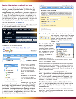
© Copyright 2026