
Table of Contents D-Link DSL-2730B User Manual i
Table of Contents
D-Link DSL-2730B User Manual
i
Table of Contents
Table of Contents
PACKAGE CONTENTS ...........................................................................................1
SYSTEM REQUIREMENTS ......................................................................................1
FEATURES ...........................................................................................................2
HARDWARE OVERVIEW .........................................................................................3
Connections ..................................................................................................3
LEDs ..............................................................................................................4
HARDWARE OVERVIEW .........................................................................................6
WPS Button ...................................................................................................6
ADVANCED W IRELESS ....................................................................................... 48
Advanced Settings ...................................................................................... 49
MAC Filtering .............................................................................................. 52
Security Settings ......................................................................................... 53
PORT FORWARDING........................................................................................... 57
DMZ ................................................................................................................ 59
PARENTAL CONTROL.......................................................................................... 59
Block Website ............................................................................................. 60
Block MAC Address .................................................................................... 61
FILTERING OPTIONS .......................................................................................... 62
Inbound Filtering ......................................................................................... 63
Outbound Filtering ...................................................................................... 64
Bridge Filtering............................................................................................ 65
DNS SETUP...................................................................................................... 66
DYNAMIC DNS SETUP ....................................................................................... 67
NETWORK TOOLS .............................................................................................. 68
Port Mapping .............................................................................................. 69
IGMP ........................................................................................................... 70
Quality of Service ....................................................................................... 71
Queue Configuration .................................................................................. 72
QoS Classification ...................................................................................... 73
UPnP .......................................................................................................... 77
DSL ............................................................................................................. 78
SNMP ......................................................................................................... 79
TR-069 ........................................................................................................ 80
ROUTING .......................................................................................................... 81
Static Route ................................................................................................ 82
Default Gateway ......................................................................................... 83
RIP .............................................................................................................. 83
SCHEDULES ...................................................................................................... 84
INSTALLATION .....................................................................................................7
BEFORE YOU BEGIN .............................................................................................7
INSTALLATION NOTES ...........................................................................................7
Information you will need from your ADSL Service Provider ........................9
Information you will need about DSL-2730B ...............................................10
Information you will need about your LAN or Computer ............................. 11
DEVICE INSTALLATION ........................................................................................ 11
Power on Router .........................................................................................12
Factory Reset Button...................................................................................12
Network Connections ..................................................................................13
CONFIGURATION ...............................................................................................14
W EB-BASED CONFIGURATION UTILITY .................................................................14
QUICK SETUP ....................................................................................................15
INTERNET SETUP ...............................................................................................25
PPPoE .........................................................................................................26
IP over Ethernet...........................................................................................29
Bridge ..........................................................................................................32
PPP over ATM (PPPoA) ..............................................................................33
IP over ATM (IPoA) ......................................................................................36
W IRELESS SETTINGS .........................................................................................39
Wireless Basics ...........................................................................................40
Wireless Security .........................................................................................41
LOCAL NETWORK ...............................................................................................45
Use the Router for DHCP ............................................................................46
Disable the DHCP Server ............................................................................46
Add DHCP Reservation List ........................................................................46
TIME AND DATE ..................................................................................................47
MAINTENANCE .................................................................................................. 85
SYSTEM ............................................................................................................ 85
FIRMWARE UPDATE ........................................................................................... 86
ACCESS CONTROLS .......................................................................................... 87
Account Password ...................................................................................... 88
Services ...................................................................................................... 89
IP Address .................................................................................................. 90
DIAGNOSTICS .................................................................................................... 91
ADVANCED .........................................................................................................48
D-Link DSL-2730B User Manual
ii
Table of Contents
SYSTEM LOG .....................................................................................................92
STATUS ...............................................................................................................93
DEVICE INFO......................................................................................................93
W IRELESS CLIENTS ............................................................................................94
DHCP CLIENTS .................................................................................................94
LOGS ................................................................................................................95
STATISTICS ........................................................................................................96
ROUTING INFO ...................................................................................................97
HELP ....................................................................................................................98
TROUBLESHOOTING ........................................................................................99
NETWORKING BASICS ...................................................................................101
CHECK YOUR IP ADDRESS ...............................................................................101
STATICALLY ASSIGN AN IP ADDRESS .................................................................102
TECHNICAL SPECIFICATIONS .......................................................................103
D-Link DSL-2730B User Manual
iii
Section 1 - Product Overview
Package Contents
•
•
•
•
•
•
DSL-2730B Wireless N 150 ADSL2+ 4-Port Ethernet Router
Power Adapter
CD-ROM with User Manual
One twisted-pair telephone cable used for ADSL connection
One straight-through Ethernet cable
One Quick Installation Guide
Warning: The Router must be used with the power adapter included with the device.
System Requirements
•
•
•
ADSL Internet service
Computer with:
• 200MHz Processor
• 64MB Memory
• CD-ROM Drive
• Ethernet Adapter with TCP/IP Protocol Installed
• Internet Explorer v6 or later, FireFox v1.5, or Safari 1.3 or above
• Windows 2000/XP/Vista
D-Link Click'n Connect Utility
D-Link DSL-2730B User Manual
1
Section 1 - Product Overview
11
Features
•
•
•
•
•
•
•
•
•
•
•
•
•
PPP (Point-to-Point Protocol) Security – The Router supports PAP (Password Authentication Protocol) and CHAP (Challenge Handshake
Authentication Protocol) for PPP connections. The Router also supports MSCHAP.
DHCP Support – Dynamic Host Configuration Protocol automatically and dynamically assigns all LAN IP settings to each host on your
network. This eliminates the need to reconfigure every host whenever changes in network topology occur.
Network Address Translation (NAT) – For small office environments, the Router allows multiple users on the LAN to access the Internet
concurrently through a single Internet account. This provides Internet access to everyone in the office for the price of a single user. NAT
improves network security in effect by hiding the private network behind one global and visible IP address. NAT address mapping can also be
used to link two IP domains via a LAN-to-LAN connection.
TCP/IP (Transfer Control Protocol/Internet Protocol) – The Router supports TCP/IP protocol, the language used for the Internet. It is
compatible with access servers manufactured by major vendors.
RIP-1/RIP-2 – The Router supports both RIP-1 and RIP-2 exchanges with other routers. Using both versions lets the Router to communicate
with all RIP enabled devices.
Static Routing – This allows you to select a data path to a particular network destination that will remain in the routing table and never “age
out”. If you wish to define a specific route that will always be used for data traffic from your LAN to a specific destination within your LAN (for
example to another router or a server) or outside your network (to an ISP defined default gateway for instance).
Default Routing – This allows you to choose a default path for incoming data packets for which the destination address is unknown. This is
particularly useful when/if the Router functions as the sole connection to the Internet.
ATM (Asynchronous Transfer Mode) – The Router supports Bridged Ethernet over ATM (RFC1483), IP over ATM (RFC1577), and PPP
over ATM (RFC 2364).
Precise ATM Traffic Shaping – Traffic shaping is a method of controlling the flow rate of ATM data cells. This function helps to establish the
Quality of Service for ATM data transfer.
High Performance – Very high rates of data transfer are possible with the Router; ADSL2+ full rate supports up to 24Mbps downstream and
1Mbps upstream.
Full Network Management – The Router incorporates SNMP (Simple Network Management Protocol) support for web-based management
and text-based network management via an RS-232 or Telnet connection.
Telnet Connection – The Telnet enables a network manager to access the Router’s management software remotely.
Easy Installation – The Router uses a web-based graphical user interface program for convenient management access and easy set up.
Any common web browser software can be used to manage the Router.
D-Link DSL-2730B User Manual
2
Section 1 - Product Overview
Hardware Overview
Connections
Antenna
Ethernet Ports
Use the Ethernet ports to connect
the Router to a computer or an
Ethernet LAN.
ADSL Port
Use the ADSL cable to connect
to your telephone line (RJ-11
port).
D-Link DSL-2730B User Manual
Wireless Button
Push it to enable the
Wireless. Push again to
disable it.
3
Reset Button
To manually reset, depress button
with the power on for at least
seven seconds.
Power Button
Push in to power-on the
Router. Push again to
power-off the Router.
Power Insert
Use the adapter shipped with
the Router to connect to power
source.
Section 1 - Product Overview
Hardware Overview
LEDs
D-Link DSL-2730B User Manual
4
Section 1 - Product Overview
LED
Description
Power
A steady green light indicates the unit is powered on. When the device is powered off this remains
dark. Lights steady green during power on self-test (POST). Once the connection status has been
settled, the light will light steady green. If the indicator lights steady red after the POST, the
system has failed and the device should be rebooted.
LAN
A solid green light indicates a valid link on startup. This light will blink when there is activity
currently passing through the Ethernet port.
WLAN
A solid green light indicates a valid link on startup. This light will blink when there is activity
currently passing through the Wireless LAN.
DSL
A steady green light indicates a valid ADSL connection. This will light after the ADSL negotiation
process has been settled. A blinking green light indicates the DLS is attempting to synchronize.
Internet A solid green light indicates the WAN IP address from IPCP or DHCP and DSL is up or a static IP
address is configured and PPP negotiation has been successfully completed. If the indicator blinks
green, this means the Router is active. If the Router power is off, this remains dark. A solid red light
indicates there is no DHCP response, no PPPoE response, PPPoE authentication has failed, and/or
there is no IP.
D-Link DSL-2730B User Manual
5
Section 1 - Product Overview
Hardware Overview
WPS Button
The Router supports WPS (Wi-Fi Protected Setup). WPS is a standard for easy and secure establishment of a wireless network. With WPS you can
setup and protect your wireless network in just a few easy steps.
The WPS Push Button is located at the right side of the Router. Press the button to enable the WPS function. The light blinks when WPS is
successfully triggered. When the connection is successfully established between the Router and the client, the blue light will be solid and remain for
five seconds. After the light is off, the Router is ready for configuring a new WPS connection.
Note: To use WPS with the Router, you need to have Wireless Clients that support WPS. If you have 1 or more Wireless Clients without WPS
support, it is advised to secure your network manually using the Setup Wizard.
D-Link DSL-2730B User Manual
6
Section 2 – Installation
Installation
This section will walk you through the installation process. Placement of the Router is very important. Do not place the Router in an enclosed area
such as a closet, cabinet, or in the attic or garage.
Before You Begin
Please read and make sure you understand all the prerequisites for proper installation of your new Router. Have all the necessary information and
equipment on hand before beginning the installation.
Installation Notes
In order to establish a connection to the Internet it will be necessary to provide information to the Router that will be stored in its memory. For some
users, only their account information (Username and Password) is required. For others, various parameters that control and define the Internet
connection will be required. You can print out the two pages below and use the tables to list this information. This way you have a hard copy of all
the information needed to setup the Router. If it is necessary to reconfigure the device, all the necessary information can be easily accessed. Be
sure to keep this information safe and private.
Low Pass Filters
Since ADSL and telephone services share the same copper wiring to carry their respective signals, a filtering mechanism may be necessary to
avoid mutual interference. A low pass filter device can be installed for each telephone that shares the line with the ADSL line. These filters are easy
to install passive devices that connect to the ADSL device and/or telephone using standard telephone cable. Ask your service provider for more
information about the use of low pass filters with your installation.
Operating Systems
The DSL-2730B uses an HTML-based web interface for setup and management. The Web configuration manager may be accessed using any
operating system capable of running web browser software, including Windows 98 SE, Windows ME, Windows 2000, Windows XP, and Windows
Vista.
D-Link DSL-2730B User Manual
7
Section 2 – Installation
Web Browser
Any common Web browser can be used to configure the Router using the Web configuration management software. The program is designed to
work best with more recently released browsers such as Opera, Microsoft Internet Explorer® version 6.0, Netscape Navigator® version 6.2.3, or
later versions. The Web browser must have JavaScript enabled. JavaScript is enabled by default on many browsers. Make sure JavaScript has not
been disabled by other software (such as virus protection or web user security packages) that may be running on your computer.
Ethernet Port (NIC Adapter)
Any computer that uses the Router must be able to connect to it through the Ethernet port on the Router. This connection is an Ethernet connection
and therefore requires that your computer be equipped with an Ethernet port as well. Most notebook computers are now sold with an Ethernet port
already installed. Likewise, most fully assembled desktop computers come with an Ethernet NIC adapter as standard equipment. If your computer
does not have an Ethernet port, you must install an Ethernet NIC adapter before you can use the Router. If you must install an adapter, follow the
installation instructions that come with the Ethernet NIC adapter.
Additional Software
It may be necessary to install software on your computer that enables the computer to access the Internet. Additional software must be installed if
you are using the device a simple bridge. For a bridged connection, the information needed to make and maintain the Internet connection is stored
on another computer or gateway device, not in the Router itself.
If your ADSL service is delivered through a PPPoE or PPPoA connection, the information needed to establish and maintain the Internet connection
can be stored in the Router. In this case, it is not necessary to install software on your computer. It may however be necessary to change some
settings in the device, including account information used to identify and verify the connection.
All connections to the Internet require a unique global IP address. For bridged connections, the global IP settings must reside in a TCP/IP enabled
device on the LAN side of the bridge, such as a PC, a server, a gateway device such as a router or similar firewall hardware. The IP address can be
assigned in a number of ways. Your network service provider will give you instructions about any additional connection software or NIC
configuration that may be required.
D-Link DSL-2730B User Manual
8
Section 2 – Installation
Information you will need from your ADSL Service Provider
Username
This is the Username used to log on to your ADSL service provider’s network. Your ADSL service provider uses this to identify your account.
Password
This is the Password used, in conjunction with the Username above, to log on to your ADSL service provider’s network. This is used to verify the
identity of your account.
WAN Setting / Connection Type
These settings describe the method your ADSL service provider uses to transport data between the Internet and your computer. Most users will use
the default settings. You may need to specify one of the following WAN Setting and Connection Type configurations (Connection Type settings listed
in parenthesis):
• PPPoE/PPPoA (PPPoE LLC, PPPoE VC-Mux, PPPoA LLC, or PPPoA VC-Mux)
• Dynamic IP Address (1483 Bridged IP LLC or 1483 Bridged IP VC-Mux)
• Static IP Address (1483 Bridged IP LLC, 1483 Bridged IP VC Mux, 1483 Routed IP LLC, 1483 Routed IP VC-Mux)
• Bridge Mode (1483 Bridged IP LLC or 1483 Bridged IP VC Mux)
Modulation Type
ADSL uses various standardized modulation techniques to transmit data over the allotted signal frequencies. Some users may need to change the
type of modulation used for their service. The default DSL modulation (Autosense) used for the Router automatically detects all types of ADSL,
ADSL2, and ADSL2+ modulation.
Security Protocol
This is the method your ADSL service provider will use to verify your Username and Password when you log on to their network. Your Router
supports the PAP and CHAP protocols.
VPI
Most users will not be required to change this setting. The Virtual Path Identifier (VPI) is used in conjunction with the Virtual Channel Identifier (VCI)
to identify the data path between your ADSL service provider’s network and your computer. If you are setting up the Router for multiple virtual
connections, you will need to configure the VPI and VCI as instructed by your ADSL service provider for the additional connections. This setting can
be changed in the WAN Settings window of the web management interface.
VCI
Most users will not be required to change this setting. The Virtual Channel Identifier (VCI) used in conjunction with the VPI to identify the data path
between your ADSL service provider’s network and your computer. If you are setting up the Router for multiple virtual connections, you will need to
configure the VPI and VCI as instructed by your ADSL service provider for the additional connections. This setting can be changed in the WAN
Settings window of the web management interface.
D-Link DSL-2730B User Manual
9
Section 2 – Installation
Information you will need about DSL-2730B
Username
This is the Username needed access the Router’s management interface. When you attempt to connect to the device through a web browser you
will be prompted to enter this Username. The default Username for the Router is “admin.” The user cannot change this.
Password
This is the Password you will be prompted to enter when you access the Router’s management interface. The default Password is “admin.” The
user may change this.
LAN IP addresses for the DSL-2730B
This is the IP address you will enter into the Address field of your web browser to access the Router’s configuration graphical user interface (GUI)
using a web browser. The default IP address is 192.168.1.1. This may be changed to suit any IP address scheme the user desires. This address will
be the base IP address used for DHCP service on the LAN when DHCP is enabled.
LAN Subnet Mask for the DSL-2730B
This is the subnet mask used by the DSL-2730B, and will be used throughout your LAN. The default subnet mask is 255.255.255.0. This can be
changed later.
D-Link DSL-2730B User Manual
10
Section 2 – Installation
Information you will need about your LAN or Computer
Ethernet NIC
If your computer has an Ethernet NIC, you can connect the DSL-2730B to this Ethernet port using an Ethernet cable. You can also use the Ethernet
ports on the DSL-2730B to connect to other computer or Ethernet devices.
DHCP Client status
Your Router is configured, by default, to be a DHCP server. This means that it can assign an IP address, subnet mask, and a default gateway
address to computers on your LAN. The default range of IP addresses the DSL-2730B will assign are from 192.168.1.2 to 192.168.1.254. Your
computer (or computers) needs to be configured to obtain an IP address automatically (that is, they need to be configured as DHCP clients.)
It is recommended that you collect and record this information here, or in some other secure place, in case you have to re-configure your ADSL
connection in the future.
Once you have the above information, you are ready to setup and configure your DSL-2730B.
Device Installation
The DSL-2730B connects two separate physical interfaces, an ADSL (WAN) and an Ethernet (LAN) interface. Place the Router in a location where
it can be connected to the various devices as well as to a power source. The Router should not be located where it will be exposed to moisture or
excessive heat. Make sure the cables and power cord are placed safely out of the way so they do not create a tripping hazard. As with any electrical
appliance, observe common sense safety procedures.
The Router can be placed on a shelf or desktop, ideally you should be able to see the LED indicators on the front if you need to view them for
troubleshooting.
D-Link DSL-2730B User Manual
11
Section 2 – Installation
Power on Router
The Router must be used with the power adapter included with the device.
1. Insert the AC Power Adapter cord into the power receptacle located on the rear panel of the Router and plug the adapter into a suitable
nearby power source.
2. Depress the Power button into the on position. You should see the Power LED indicator light up and remain lit.
3. If the Ethernet port is connected to a working device, check the LAN LED indicators to make sure the connection is valid. The Router will
attempt to establish the ADSL connection. If the ADSL line is connected and the Router is properly configured, the DSL LED should light up
after several seconds. If this is the first time installing the device, some settings may need to be changed before the Router can establish a
connection.
Factory Reset Button
The Router may be reset to the original factory default settings by using a ballpoint or paperclip to gently push down the reset button in the following
sequence:
1. Ensure the Router is powered on.
2. Press and hold the reset button on the back of the device for approximately 10 seconds.
3. This process should take around 1 to 2 minutes.
Remember that this will wipe out any settings stored in flash memory including user account information and LAN IP settings. The device settings
will be restored to the factory default IP address 192.168.1.1 and the subnet mask is 255.255.255.0, the default management Username is “admin”
and the default Password is “admin.”
D-Link DSL-2730B User Manual
12
Section 2 – Installation
Network Connections
Connect ADSL Line
Use the ADSL cable included with the Router to connect it to a telephone wall socket or receptacle. Plug one end of the cable into the ADSL port
(RJ-11 receptacle) on the rear panel of the Router and insert the other end into the RJ-11 wall socket. If you are using a low pass filter device, follow
the instructions included with the device or given to you by your service provider. The ADSL connection represents the WAN interface, the
connection to the Internet. It is the physical link to the service provider’s network backbone and ultimately to the Internet.
Connect Router to Ethernet
The Router may be connected to a single computer or Ethernet device through the 10BASE-TX Ethernet port on the rear panel. Any connection to
an Ethernet concentrating device such as a switch or hub must operate at a speed of 10/100 Mbps only. When connecting the Router to any
Ethernet device that is capable of operating at speeds higher than 10Mbps, be sure that the device has auto-negotiation (NWay) enabled for the
connecting port. Use standard twisted-pair cable with RJ-45 connectors. The RJ-45 port on the Router is a crossed port (MDI-X). Follow standard
Ethernet guidelines when deciding what type of cable to use to make this connection. When connecting the Router directly to a PC or server use a
normal straight-through cable. You should use a crossed cable when connecting the Router to a normal (MDI-X) port on a switch or hub. Use a
normal straight-through cable when connecting it to an uplink (MDI-II) port on a hub or switch. The rules governing Ethernet cable lengths apply to
the LAN to Router connection. Be sure that the cable connecting the LAN to the Router does not exceed 100 meters.
Hub or Switch to Router Connection
Connect the Router to an uplink port (MDI-II) on an Ethernet hub or switch with a straight-through cable. If you wish to reserve the uplink port on the
switch or hub for another device, connect to any on the other MDI-X ports (1x, 2x, etc.) with a crossed cable.
Computer to Router Connection
You can connect the Router directly to a 10/100BASE-TX Ethernet adapter card (NIC) installed on a PC using the Ethernet cable provided.
D-Link DSL-2730B User Manual
13
Section 3 – Configuration
Configuration
This section will show you how to set up and configure your new D-Link Router using the Web-based configuration utility.
Web-based Configuration Utility
Connect to the Router
To configure the WAN connection used by the Router it is first necessary to communicate with the Router through its management interface, which
is HTML-based and can be accessed using a web browser. The easiest way to make sure your computer has the correct IP settings is to configure
it to use the DHCP server in the Router. The next section describes how to change the IP configuration for a computer running a Windows operating
system to be a DHCP client.
To access the configuration utility, open a web-browser such as Internet
Explorer and enter the IP address of the router (192.168.1.1).
Type “admin” for the Username, “admin” in the Password field. In the
Validate entry field, type the letters that appear below. If you cannot read
the letters, click on refresh to view a new randomly generated set of five
letters. The Validate field is not case sensitive so upper or lower case
letters work. Click Login when the you have filled in the three login fields.
If you get a Page Cannot be Displayed error, please refer to the
Troubleshooting section for assistance.
D-Link DSL-2730B User Manual
14
Section 3 – Configuration
Quick Setup
This chapter is concerned with using your computer to configure the WAN connection. The following chapter describes the various windows used to
configure and monitor the Router including how to change IP settings and DHCP server setup.
QUICK SETUP
Click the Setup Wizard button in the middle of the main
window of the Router’s opening page to launch a series of
setup windows.
D-Link DSL-2730B User Manual
15
Section 3 – Configuration
QUICK SETUP – OPENING WINDOW
The first window of the Setup Wizard lists the basic steps in the process.
These steps are as follows:
1.
2.
3.
4.
5.
Change the Router password.
Configure time and date of the Router.
Configure the connection to the Internet.
Configure the connection to Wireless Network.
Save the new configuration settings and reboot the system.
QUICK SETUP – CHANGE YOUR ROUTER PASSWORD
This window of the Setup Wizard is used to change the Router
password. D-Link recommends to help secure your network, the user
should change the Current Password from the factory default, admin.
The New Password should be between 1 and 16 alphanumeric
characters. Once you have filled out the fields in this window, including
re-typing the new password in the Confirm Password field, click the Next
button to continue.
If you do not want to change the password, click the Skip button to
proceed to the next step.
D-Link DSL-2730B User Manual
16
Section 3 – Configuration
QUICK SETUP – SET TIME AND DATE
This page allows you to configure the time and date of the Router.
Select Automatically synchronize with Internet time servers to
select first and second NTP (Network Time Protocol) server.
Select a time zone in which you are located from the Time Zone list.
Select Enable Daylight Saving and configure the daylight saving
information, if the area you are located has daylight saving.
Click the Next button to continue.
D-Link DSL-2730B User Manual
17
Section 3 – Configuration
QUICK SETUP – SELECT THE INTERNET CONNECTION TYPE
Now use the drop-down menus to select the Country, Internet Service
Provider, Protocol, and Connection Type used for the Internet
connection, and enter VPI and VCI values if applicable. Your ISP has
given this information to you—any information that is not required for
your provider will automatically be grayed out in this window and
subsequent Quick Setup windows.
The available Protocol modes are: PPPoE, PPPoA, Dynamic IP, Static
IP, and Bridge.
Select PPPoE or PPPoA in the Protocol drop-down list to see the
D-Link DSL-2730B User Manual
18
Section 3 – Configuration
QUICK SETUP – PPPOE/PPPOA CONFIGURATION
Type in the User Name and Password used to identify and verify your
account to the ISP. If you are instructed to change the VPI or VCI
number, type in the correct setting in the available entry fields. Most
users will not need to change these settings. The Internet connection
cannot function if these values are incorrect.
Some users may have to adjust the Connection Type from the
drop-down menu. The available connection and encapsulation types are
VC-Mux, and LLC.
Select Dynamic IP in the Protocol drop-down list to see the following
items.
D-Link DSL-2730B User Manual
19
Section 3 – Configuration
QUICK SETUP – DYNAMIC IP CONFIGURATION
If you are instructed to change the VPI or VCI numbers, type in the
correct setting in the available entry fields. The Internet connection
cannot function if these values are incorrect. Select the specific
Connection Type from the drop-down menu. The available connection
and encapsulation types are LLC and VC-Mux. You may want to.
Select Static IP in the Protocol drop-down list to see the following
items.
D-Link DSL-2730B User Manual
20
Section 3 – Configuration
QUICK SETUP – STATIC IP CONFIGURATION
Enter values for VPI, VCI, IP Address, Subnet Mask, Default
Gateway IP address, and Primary DNS Server instructed by your
ISP. The Internet connection cannot function if these values are
incorrect.
Select the specific Connection Type from the drop-down menu. The
available connection and encapsulation types are LLC, and VC-Mux.
Select Bridge in the Protocol drop-down list to see the following
items.
D-Link DSL-2730B User Manual
21
Section 3 – Configuration
QUICK SETUP – BRIDGE MODE CONFIGURATION
If you are instructed to change the VPI or VCI numbers, type in the
correct setting in the available entry fields. The Internet connection
cannot function if these values are incorrect.
Select the specific Connection Type from the drop-down menu. The
available connection and encapsulation types are LLC and VC-Mux.
Click Next to go to the last Setup Wizard window.
D-Link DSL-2730B User Manual
22
Section 3 – Configuration
QUICK SETUP – Configure Wireless Network
To enable the Wireless feature of this device, tick the Enable
Your Wireless Network option. Enter an SSID (this is the
wireless network name). Choose whether to make the wireless
network Visible or Invisible.
The Wireless Network will be unsecure if the Security Level is
set to None. There are 3 security options that the user can
choose called WEP, WPA-PSK or WPA2-PSK.If the user
requires no wireless security, deselect the Enable Your
Wireless Network option. Click Next to continue.
D-Link DSL-2730B User Manual
23
Section 3 – Configuration
QUICK SETUP – COMPLETED & RESTART CONFIRMATION
Finally you can see the Setup Summary of the configurations you did
through the wizard. If you are satisfied that you have entered all the
necessary information correctly, click the Restart button to save the new
configuration settings and restart the Router. If you need to change
settings from a previous window, click the Back button.
QUICK SETUP – REBOOT TIME INDICATOR
The following window opens to indicate the amount of time it will take to
reboot the Router. Once the rebooting process is completed, it will go
back to the main web page.
D-Link DSL-2730B User Manual
24
Section 3 – Configuration
Internet Setup
To configure the Router’s basic configuration settings without running the Setup Wizard, you can access the windows used to configure ADSL
Setup, LAN Setup, Time and Date, and Parental Control settings directly from the Setup directory.
To access the Internet Setup window, click Internet Setup on the left side of the first window that appears when you successfully access the web
manager.
Internet Connection Settings
Click the Add button to add a new Internet connection. A new menu
appears.
After the Internet connection has been established, this menu will
display basic information about the Internet (WAN) connection.
D-Link DSL-2730B User Manual
25
Section 3 – Configuration
PPPoE
For a PPPoE connection, first choose the EoA option under ATM Interface Configuration in order to view the parameters to configure for this
connection type.
VPI: Enter the correct VPI used in this field.
VCI: Enter the correct VCI used in this field.
Select DSL Link Type: Select the correct DSL Link Type here. For
PPPoE use the EoA (Ethernet over ATM) option. This is the default
setting.
Encapsulation Mode: Choose the appropriate Encapsulation Mode here.
Service Category: Choose the appropriate Service Category here.
Enable Quality of Service: Tick this option to enable Quality of Service.
Select WAN Service Type: Choose the appropriate WAN Service Type
here. Click PPP over Ethernet (PPPoE) for this section.
Enter Service Description: This field will display an automated service
description.
D-Link DSL-2730B User Manual
26
Section 3 – Configuration
P P P C onfiguration
The parameters listed in the PPP Configuration menu are used for PPPoE and PPPoA connections.
PPP Username: Enter the account username in this field.
PPP Password: Enter the account password in this field.
PPPoE Service Name: Enter the service name here (optional).
Authentication Method: Choose the appropriate authentication method
here. If not sure leave this option on Auto.
Enable NAT: Tick this option to enable NAT for this connection. NAT is
enabled by default.
Enable Fullcone NAT: This option appears only if NAT is enabled (NAT is
enabled by default). Tick this option to enable Fullcone NAT for this
connection.
Enable Firewall: This is enabled by default. It provides basic firewall
protection that closes unused ports. Click in the box to remove the check
mark to disabled this function.
Dial on Demand: Tick this option to enable dial on demand for this
connection. When this is enabled, the PPP session will timeout and
disconnect when the connection is idle. It will automatically reconnect
whenever it receives a connection request from the LAN side.
Use Static IPv4: Tick this option to use a Static IP version 4 address for
this connection.
Static IPv4 Address: When Use Static IPv4 is selected, this selection
appears. Enter the Static IP version 4 address used here.
Enable IGMP Multicast: Tick this option to allow IGMP packets to go
through the WAN interface in both directions.
D-Link DSL-2730B User Manual
27
Section 3 – Configuration
Default Gateway and DNS Settings
Selected WAN Interface: The user can choose the WAN interface to
use this connection.
Obtain DNS info from a WAN interface: The user can choose to
obtain DNS Server IP addresses automatically from the ISP.
Use the following Static DNS IP address: The user can manually
enter the DNS Server IP addresses to use for this connection.
Click the Apply button to accept these changes.
Click the Cancel button to discard these changes.
D-Link DSL-2730B User Manual
28
Section 3 – Configuration
IP over Ethernet
For an IP over Ethernet connection, first choose the EoA option under ATM Interface Configuration in order to view the parameters to configure
for this connection type.
Click the EoA and IP over Ethernet radio buttons to see the
following selections.
VPI: Enter the correct VPI used in this field.
VCI: Enter the correct VCI used in this field.
Select DSL Link Type: Select the correct DSL Link Type here.
For PPPoE Mode select EoA.
Encapsulation Mode: Choose the appropriate Encapsulation
Mode here.
Service Category: Choose the appropriate Service Category
here.
Select Connection Mode: Choose the connection mode of
your Internet link here.
Enable Quality of Service: Tick this option to enable Quality of
Service.
Select WAN Service Type: Choose the appropriate WAN
Service Type here. Click IP over Ethernet for this section.
Enter Service Description: This field will display an automated
service description.
D-Link DSL-2730B User Manual
29
Section 3 – Configuration
WAN IP Settings
Obtain an IP address automatically: Choose this option to obtain an IP
address automatically for this connection.
Option 60 Vender ID: Enter the Option 60 Vendor ID value used in the
field.
Option 61 IAID: Enter the Option 61 IAID value used in the field.
Option 61 DUID: Enter the Option 61 DUID value used in the field.
Option 125: Tick the radio buttons to enable or disable the Option 125
value.
Use the following Static IP address: Choose this option to manually
enter a static IP address used for this connection. Configure the IP
settings below.
WAN IP Address: Enter the WAN IP address used in the field.
WAN Subnet Mask: Enter the WAN subnet mask used in the field.
WAN Gateway IP Address: Enter the WAN gateway IP address used in
the field.
D-Link DSL-2730B User Manual
30
Section 3 – Configuration
NAT, Default Gateway and DNS Settings
Enable NAT: Tick this option to enable NAT for this connection.
Enable Fullcone NAT: When Enable NAT is selected, this selection
appears. Tick this option to enable Fullcone NAT for this connection.
Enable firewall: Tick this option to enable firewall for this connection.
Enable IGMP Multicast: Tick this option to allow IGMP packets to go
through the WAN interface in both directions.
Selected WAN Interface: The user can choose the WAN interface to
use this connection.
Obtain DNS info from a WAN interface: Tick the radio button to obtain
DNS Server IP addresses automatically from the ISP.
WAN Interface Selected: Display the WAN interface that has been
selected in the Routing – Default Gateway section.
Use the following Static DNS IP address: Tick the radio button to
manually enter the DNS Server IP addresses below for this connection.
Primary DNS Server: Enter the main DNS server IP address.
Secondary DNS Server: Enter the secondary DNS server IP address.
Click the Apply button to accept these changes.
Click the Cancel button to discard these changes.
D-Link DSL-2730B User Manual
31
Section 3 – Configuration
Bridge
For a Bridge connection, first choose the EoA option under ATM Interface Configuration in order to view the parameters to configure for this
connection type.
Click the EoA and Bridging radio buttons to see the following
selections.
VPI: Enter the correct VPI used in this field.
VCI: Enter the correct VCI used in this field.
Select DSL Link Type: Select the correct DSL Link Type here. For
PPPoE Mode select EoA.
Encapsulation Mode: Choose the appropriate Encapsulation Mode
here.
Service Category: Choose the appropriate Service Category here.
Select Connection Mode: Choose the connection mode of your
Internet link here.
Enable Quality of Service: Tick this option to enable Quality of Service.
Select WAN Service Type: Choose the appropriate WAN Service Type
here. Click Bridging for this section.
Enter Service Description: This field will display an automated service
description.
Click the Apply button to accept these changes.
Click the Cancel button to discard these changes.
D-Link DSL-2730B User Manual
32
Section 3 – Configuration
PPP over ATM (PPPoA)
For a PPPoA connection, first choose the PPPoA option under ATM Interface Configuration in order to view the parameters to configure for this
connection type.
Click the PPPoA radio button to see the following selections.
VPI: Enter the correct VPI used in this field.
VCI: Enter the correct VCI used in this field.
Select DSL Link Type: Select the correct DSL Link Type here. For
PPPoE Mode select PPPoA.
Encapsulation Mode: Choose the appropriate Encapsulation Mode
here.
Service Category: Choose the appropriate Service Category here.
Enable Quality of Service: Tick this option to enable Quality of Service.
Enter Service Description: This field will display an automated service
description.
D-Link DSL-2730B User Manual
33
Section 3 – Configuration
P P P C onfiguration
The parameters listed in the PPP Configuration menu are used for PPPoE and PPPoA connections.
PPP Username: Enter the account username in this field.
PPP Password: Enter the account password in this field.
PPPoE Service Name: Enter the service name here (optional).
Authentication: Choose the appropriate authentication method here. If
not sure leave this option on Auto.
Enable NAT: Tick this option to enable NAT for this connection.
Enable Fullcone NAT: When Enable NAT is selected, this selection
appears. Tick this option to enable Fullcone NAT for this connection.
Enable Firewall: This is enabled by default. It provides basic firewall
protection that closes unused ports. Click in the box to remove the check
mark to disabled this function.
Dial on Demand: Tick this option to enable dial on demand for this
connection. When this is enabled, the PPP session will timeout and
disconnect when the connection is idle. It will automatically reconnect
whenever it receives a connection request from the LAN side.
Use Static IPv4: Tick this option to use a Static IP version 4 address for
this connection.
IPv4 Address: When Use Static IPv4 is selected, this entry field
appears. Enter the Static IP version 4 address used here.
Bridge PPPoE Frames: Tick this option if you are running services on
your LAN that require PPPoE authentication or if PPPoE clients are
running on your LAN that requires authentication for services on the
WAN.
Enable IGMP Multicast: Tick this option to allow IGMP packets to go
through the WAN interface in both directions.
D-Link DSL-2730B User Manual
34
Section 3 – Configuration
Default Gateway and DNS Settings
Selected WAN Interface: The user can choose the WAN interface to
use this connection.
Obtain DNS info from a WAN interface: Tick the radio button to obtain
DNS Server IP addresses automatically from the ISP.
WAN Interface Selected: Display the WAN interface that has been
selected in the Routing – Default Gateway section.
Use the following Static DNS IP address: Tick the radio button to
manually enter the DNS Server IP addresses below for this connection.
Primary DNS Server: Enter the main DNS server IP address.
Secondary DNS Server: Enter the secondary DNS server IP address.
Click the Apply button to accept these changes.
Click the Cancel button to discard these changes.
D-Link DSL-2730B User Manual
35
Section 3 – Configuration
IP over ATM (IPoA)
For an IPoA connection, first choose the IPoA option under ATM Interface Configuration in order to view the parameters to configure for this
connection type.
Click the IPoA radio button to see the following selections.
VPI: Enter the correct VPI used in this field.
VCI: Enter the correct VCI used in this field.
Select DSL Link Type: Select the correct DSL Link Type here. For
PPPoE Mode select IPoA.
Encapsulation Mode: Choose the appropriate Encapsulation Mode
here.
Service Category: Choose the appropriate Service Category here.
Enable Quality of Service: Tick this option to enable Quality of Service.
Enter Service Description: This field will display an automated service
description.
WAN IP Address: Enter the WAN IP address used in the field.
WAN Subnet Mask: Enter the WAN subnet mask used in the field.
D-Link DSL-2730B User Manual
36
Section 3 – Configuration
NAT, Default Gateway Settings
Enable NAT: Tick this option to enable NAT for this connection.
Enable Fullcone NAT: When Enable NAT is selected, this selection
appears. Tick this option to enable Fullcone NAT for this connection.
Enable firewall: Tick this option to enable firewall for this connection.
Enable IGMP Multicast: Tick this option to allow IGMP packets to go
through the WAN interface in both directions.
Selected WAN Interface: The user can choose the WAN interface to
use this connection.
Obtain DNS info from a WAN interface: Tick the radio button to obtain
DNS Server IP addresses automatically from the ISP.
WAN Interface Selected: Display the WAN interface that has been
selected in the Routing – Default Gateway section.
Use the following Static DNS IP address: Tick the radio button to
manually enter the DNS Server IP addresses below for this connection.
Primary DNS Server: Enter the main DNS server IP address.
Secondary DNS Server: Enter the secondary DNS server IP address.
Click the Apply button to accept these changes.
Click the Cancel button to discard these changes.
D-Link DSL-2730B User Manual
37
Section 3 – Configuration
S ervic e C ategory
When configuring the Service Category for any of the above mentioned connection configurations there are 5 different variations to choose from.
UBR Without PCR
There are no additional fields listed when choosing this category.
UBR With PCR
Peak Cell Rate: Enter the Peak Cell Rate used.
CBR
Peak Cell Rate: Enter the Peak Cell Rate used.
Non Realtime VBR
Peak Cell Rate: Enter the Peak Cell Rate used.
Sustainable Cell Rate: Enter the Sustainable Cell Rate used.
Maximum Burst Size: Enter the Maximum Burst Size used.
Realtime VBR
Peak Cell Rate: Enter the Peak Cell Rate used.
Sustainable Cell Rate: Enter the Sustainable Cell Rate used.
Maximum Burst Size: Enter the Maximum Burst Size used.
D-Link DSL-2730B User Manual
38
Section 3 – Configuration
Wireless Settings
To access Wireless Settings, click Wireless Settings in the Setup directory.
It has two subcategories: Wireless Basics and Wireless Security. You can
either point to the Wireless Settings on the left window and click one of the
submenus, or click one of the buttons in the Wireless Settings window.
D-Link DSL-2730B User Manual
39
Section 3 – Configuration
Wireless Basics
To access Wireless Basics, point to the Wireless Settings on the left window and click Wireless Basics submenu, or click the Wireless Basics
button in the Wireless Settings window.
The two essential settings for wireless LAN operation are the
Wireless Network Name (SSID) and Wireless Channel. The
SSID (Service Set Identifier) is used to identify a group of
wireless LAN components. The SSID can be visible (broadcast)
or hidden (not broadcast).
Follow the instructions below to change basic wireless settings.
1. The Wireless LAN is enabled by default. To disable the
wireless interface, click to deselect the Enable Wireless
check box. If the wireless interface has been disabled,
click the Enable Wireless check box again to select it.
2. The Wireless Network Name (SSID) can be changed to
suit your wireless network. Remember that any wireless
device using the access point must have the same SSID
and use the same channel.
3. The Visibility Status is Visible by default. To disable SSID
Visibility Status, click the Invisible radio button.
4. Select a country where the Router is located in the
Country drop-down list.
5. The Wireless Channel may be changed to channels that
are available in your region. Channels available for
wireless LAN communication are subject to regional and
national regulation.
6. Select a wireless protocol in the 802.11 Mode drop-down
list.
7. Click Apply to save the settings.
D-Link DSL-2730B User Manual
40
Section 3 – Configuration
Wireless Security
To access Wireless Security, point to the Wireless Settings on the left window and click Wireless Security submenu, or click the Wireless
Security button in the Wireless Settings window.
In order to protect the privacy, you can setup the wireless
security. Available security modes are WEP, Auto, WPA2 Only,
and WPA Only.
1. Select a wireless security mode in the Security Mode
drop-down list.
2. Different settings based on the security mode appear at
the bottom of the window.
D-Link DSL-2730B User Manual
41
Section 3 – Configuration
WE P
When selecting WEP from the Security Mode drop-down menu,
the WEP section appears.
1. Select the WEP key length between 64 bit or 128 bit from
the drop-down list.
2. Enter the WEP key(s) in the WEP Key 1 to WEP Key 4
fields.
3. Select the authentication as Open or Shared from the
Authentication drop-down menu.
4. Click Apply to save the settings.
D-Link DSL-2730B User Manual
42
Section 3 – Configuration
Auto, W PA or W PA2
When selecting Auto, WPA2 Only or WPA Only from the Security Mode
drop-down menu, the WPA section appears.
1. In the WPA Mode drop-down menu, select between WPA-PSK and
WPA-Enterprise. Different sections appear based on the selection.
2. Enter a period of time for key updated in the Group Key Update
Interval field.
Pre-shared Key
When WPA-PSK was selected in the WPA Mode drop-down menu, this section
appears for the user to enter a shared key.
D-Link DSL-2730B User Manual
43
Section 3 – Configuration
EAP (802.1X)
When WPA-Enterprise was selected in the WPA Mode drop-down menu,
this section appears for the user to enter a shared key.
1. Enter the available period of time for authentication, Radius server
IP address, its port, and shared secret.
2. Click Apply to save the settings.
D-Link DSL-2730B User Manual
44
Section 3 – Configuration
Local Network
To access the LAN Setup window, click the LAN Setup button in the Setup directory.
To access the Local Network window, click the Local Network button in the Setup
directory.
You can configure the local network IP address to suit your preference. Many users will find
it convenient to use the default settings together with DHCP service to manage the IP
settings for their private network. The IP address of the Router is the base address used for
DHCP. In order to use the Router for DHCP on your local network, the IP address pool used
for DHCP must be compatible with the IP address of the Router. The IP addresses
available in the DHCP IP address pool will change automatically if you change the IP
address of the Router. See the next section for information on DHCP setup.
To change the Router IP Address or Subnet Mask, type in the desired values in the Router
Settings section and click the Apply button. A message pops up asking if reboot the
system. Click OK to restart the device. Your web browser should automatically be
redirected to the new IP address. You will be asked to login again to the Router’s web
manager.
The DHCP server is enabled by default for the Router’s Ethernet LAN interface. DHCP
service will supply IP settings to workstations configured to automatically obtain IP settings
that are connected to the Router though the Ethernet port. When the Router is used for
DHCP it becomes the default gateway for DHCP client connected to it. Keep in mind that if
you change the IP address of the Router the range of IP addresses in the pool used for
DHCP on the LAN will also be changed. The IP address pool can be up to 253 IP
addresses.
There are two options for DHCP service:
• You can use the Router as a DHCP server for your LAN.
• You can disable DHCP service and manually configure IP settings for workstations.
D-Link DSL-2730B User Manual
45
Section 3 – Configuration
You may also configure DNS settings when using the Router in DHCP mode (Advanced > DNS Setup). When “Obtain DNS server address
automatically“ is clicked under DNS Server Configuration on the DNS Setup window, the Router will automatically relay DNS settings to properly
configured DHCP clients. To manually enter DNS IP addresses, click the “Use the following DNS server addresses“ radio button and type in a
Preferred DNS Server and Alternate DNS Server in the fields provided. The manually configured DNS settings will be supplied to clients that are
configured to request them from the Router.
Follow the instructions below according to which of the above DHCP options you want to use. When you have configured DHCP as you want, click
the Apply button to commit the new settings. A message pops up asking if reboot the system. Click OK to restart the device.
Use the Router for DHCP
To use the built-in DHCP server, click the Enable DHCP Server radio button in the DHCP Settings section if it is not already selected. The IP
address pool settings can be adjusted. The DHCP IP Address Range starts with the lowest available IP address (default = 192.168.1.2). If you
change the IP address of the Router this will change automatically to be 1 more that the IP address of the Router. The DHCP IP Address Range
ends with the highest IP address number in the pool. Type in the DHCP Lease Time in the entry field provided. This is the amount of time in hours
that a workstation is allowed to reserve an IP address in the pool if the workstation is disconnected from the network or powered off.
Disable the DHCP Server
To disable DHCP, Click the Disable DHCP Server radio button in the DHCP Settings section and click the Apply button. A message pops up asking
if reboot the system. Click OK to restart the device. Choosing this option will gray out most of the setting options on this window and require that
workstations on the local network be configured manually or use another DHCP server to obtain IP settings.
If you configure IP settings manually, make sure to use IP addresses in the subnet of the Router. You will need to use the Router’s IP address as the
Default Gateway for the workstation in order to provide Internet access.
Add DHCP Reservation List
To add an entry to the DHCP Reservation List, click the Add button in the DHCP Reservation List section, type in an IP Address, either click the
Copy Your PC’s MAC Address button or manually enter a MAC Address, enter a Computer Name if desired, and click the Apply button. To delete
an entry from the DHCP Reservations List, tick the entry, and click the Delete button. To modify a DHCP Reservations List entry, tick the entry, click
the Edit button, and then enter the information in the appropriate fields in the Add DHCP Reservation (Optional) section. Click the Apply button. A
message pops up asking if reboot the system. Click OK to restart the device.
D-Link DSL-2730B User Manual
46
Section 3 – Configuration
Time and Date
To access the Time and Date window, click the Time and Date button in the Setup directory.
The Router provides NTP and daylight saving to configure, update and maintain the
correct time.
To configure system time on the Router, select the Automatically synchronize with
Internet time servers check box (default) and use the drop-down menu to select the
NTP server URL in the First NTP Time Server field. You may also want to choose a
Second NTP Time Server using the drop-down menu.
Use the Time Zone pull-down menu to select the correct time zone. For areas that use
Daylight Saving seasonal time adjustments, use the menu below Time Zone to configure
the settings. To configure Daylight Savings, click on the Enable Daylight Saving check
box and use the scheduling and offset menus to determine when to apply the adjustment
and by how much. Use the Daylight Savings Offset pull-down menu to subtract an
amount of time appropriate for the time zone. Use the Daylight Savings Dates menu to
determine when the Daylight Savings period will Start and End.
When you are finished, click the Apply button. Go to Maintenance > System and click
Reboot to restart the device and let your changes take effect.
D-Link DSL-2730B User Manual
47
Section 3 – Configuration
Advanced
This chapter include the more advanced features used for network management and security.
Advanced Wireless
To access Advanced Wireless, click Advanced Wireless in the Advanced directory.
It has three subcategories: Advanced Settings, MAC Filtering and
Security Settings. You can either point to the Advanced Wireless on
the left window and click one of the submenus, or click one of the
buttons in the Wireless Settings window.
D-Link DSL-2730B User Manual
48
Section 3 – Configuration
Advanced Settings
To access Advanced Settings, point to the Advanced Wireless on the left window and click Advanced Settings submenu, or click the Advanced
Settings button in the Wireless Settings window.
In this page, you can configure more advanced settings of 802.11g
wireless radio. However, it is recommended to remain as default unless
your ISP requests to change it.
Basic Rate: The wireless link rate at which information will be received
and transmitted on your wireless network.
Multicast Rate: The rate at which a message is sent to a specified
group of recipients.
Transmit Power: This is the percentage of power that should be
transmitted from your wireless router. Select from 20%, 40%, 60%, 80%,
and 100%.
Beacon Period: A packet of information that is sent from a connected
device to all other devices where it announces its availability and
readiness. A beacon interval is a period of time (sent with the beacon)
before sending the beacon again. The beacon interval may be adjusted
in milliseconds (ms).
RTS Threshold: Determines the packet size of a transmission through
the use of the router to help control traffic flow.
Fragment Threshold: Used to fragment packets which help improve
performance in the presence of radio frequency (RF) interference.
DTIM Interval: Sets the Wake-up interval for clients in power-saving
mode.
Preamble Type: This is the length of the CRC (Cyclic Redundancy
Check) block for communication between the router and wireless clients.
High network traffic areas should select Short preamble type.
D-Link DSL-2730B User Manual
49
Section 3 – Configuration
Enable Wireless: Tick the check box to enable the wireless feature of
this device. In the drop down menu select the appropriate schedule for
when the wireless feature of this device should be enabled or disabled.
Click the Add New button to go to Advanced -> Schedules page to
configure more schedules.
Wireless Network Name (SSID): Enter a wireless network name
(SSID).
Visibility Status: Click the radio buttons to make the wireless network
visible or invisible.
User Isolation: Use the drop-down menu to enable (On) or disable (Off)
wireless user isolation.
Enable: Tick to enable Wi-Fi Protection (WPS, also known as WCN).
Current PIN: The current PIN for WPS is displayed.
Generate New PIN: Click this button to generate a new WPS PIN.
Wi-Fi Protected Status: The current status of WPS is displayed.
Reset to Unconfigured: Click this button to disable WPS.
Add Wireless Device Wizard: Click this button to add a new wireless
device using WPS.
D-Link DSL-2730B User Manual
50
Section 3 – Configuration
Enable Wireless Guest network: Tick the check box to enable a
wireless guest network.
Guest SSID: Enter an additional SSID for the wireless guest network.
Visibility Status: Click the radio buttons to make the wireless guest
network visible or invisible.
User Isolation: Use the drop-down menu to enable (On) or disable (Off)
wireless user isolation.
D-Link DSL-2730B User Manual
51
Section 3 – Configuration
MAC Filtering
To access MAC Filtering, point to the Advanced Wireless on the left window and click MAC Filtering submenu, or click the MAC Filtering button
in the Wireless Settings window.
This page can help you to allow or deny certain MAC addresses to pass
through or block out.
Click Add at the bottom of the window to enter MAC address. Click
Apply at the bottom of the page to add the MAC address to the wireless
MAC filtering list.
Select Enable Wireless MAC Filter and click the Only ALLOW
computers listed to access wireless network or Only DENY
computers listed to access wireless network of the filtering policy.
Click Apply to save the settings. Go to Maintenance -> System and
click Reboot to restart the device and let the new settings take effect.
D-Link DSL-2730B User Manual
52
Section 3 – Configuration
Security Settings
To access wireless Security Settings, point to the Advanced Wireless on the left window and click Security Settings submenu, or click the
Security Settings button in the Wireless Settings window.
1. Select an SSID from the Select SSID drop-down menu.
2. Select the security type for the SSID from the Security Mode
drop-down menu.
The detail configurations for various security types are described below.
D-Link DSL-2730B User Manual
53
Section 3 – Configuration
WE P
When selecting WEP from the Security Mode drop-down menu,
the WEP section appears.
1. Select the WEP key length between 64 bit or 128 bit from
the drop-down list.
2. Enter the WEP key(s) in the WEP Key 1 to WEP Key 4
fields.
3. Select the authentication as Open or Shared from the
Authentication drop-down menu.
4. Click Apply to save the settings.
D-Link DSL-2730B User Manual
54
Section 3 – Configuration
Auto, W PA or W PA2
When selecting Auto, WPA2 Only or WPA Only from the Security
Mode drop-down menu, the WPA section appears.
1. In the WPA Mode drop-down menu, select between WPA-PSK
and WPA-Enterprise. Different sections appear based on the
selection.
2. Enter a period of time for key updated in the Group Key
Update Interval field.
Pre-shared Key
When WPA-PSK was selected in the WPA Mode drop-down menu,
this section appears for the user to enter a shared key.
D-Link DSL-2730B User Manual
55
Section 3 – Configuration
EAP (802.1X)
When WPA-Enterprise was selected in the WPA Mode
drop-down menu, this section appears for the user to enter a
shared key.
1. Enter the available period of time for authentication,
Radius server IP address, its port, and shared secret.
2. Click Apply to save the settings.
D-Link DSL-2730B User Manual
56
Section 3 – Configuration
Port Forwarding
To access the Port Forwarding window, click the Port Forwarding button in the Advanced directory.
Multiple connections are required by some applications, such as Internet
games, video conferencing, Internet telephony, and others. These
applications have difficulties working through NAT (Network Address
Translation). This section is used to open multiple ports or a range of
ports in your router and redirect data through those ports to a single PC
on your network.
1.
2.
Click the Add button to add a new Internet connection.
Once there is any Internet connection in the table, the Edit and
Remove buttons appears. To edit an entry in the table, tick the
Edit check box of the entry and click the Edit button. To remove
an entry, tick the Remove check box of the entry and click the
Remove button.
Click the Add button to see the Port Forwarding Setup section.
D-Link DSL-2730B User Manual
57
Section 3 – Configuration
Select a Service: Select a pre-defined port forwarding rule.
Server Name: Enter a custom rule name.
Schedule: Select a schedule when this rule will be active. Rules in
the list can be configured in Advanced -> Schedules. Click the View
Available Schedules button to go to the page.
Server IP Address: Enter the internal server IP address.
External Ports: Enter the start and end external ports used.
Protocol: Select a protocol applicable to this rule.
Internal Ports: Enter the start and end internal ports used.
Remote IP: Enter a remote IP address used.
The Internal Port End can’t be changed. It is the same as External
Port End normally and will be the same as the Internal Port Start or
External Port End if either one is modified.
Click the Apply button to accept the changes.
Click the Cancel button to discard the changes.
D-Link DSL-2730B User Manual
58
Section 3 – Configuration
DMZ
To access the DMZ (Demilitarized Zone) window, click the DMZ button in the Advanced directory.
Since some applications are not compatible with NAT, the Router supports
use of a DMZ IP address for a single host on the LAN. This IP address is
not protected by NAT and will therefore be visible to agents on the Internet
with the right type of software. Keep in mind that any client PC in the DMZ
will be exposed to various types of security risks. If you use the DMZ, take
measures (such as client-based virus protection) to protect the remaining
client PCs on your LAN from possible contamination through the DMZ.
To designate a DMZ IP address, type in the IP Address of the server or
device on your LAN, and click the Apply button.
Parental Control
To access the Parent Control menu, click the Parent Control link in the Advanced directory.
It has one subcategories: Block MAC Address. You can either point to
the Parental Control on the left window and click the submenu, or click
the buttons in the Parental Control window.
D-Link DSL-2730B User Manual
59
Section 3 – Configuration
Block Website
To access the Block Website menu, click the Block Website button in the Parental Control menu.
Use this window to deny access to specified Internet website using the
URL (Universal Resource Lookup), that is, the named web address.
Click Add to see the Block Website configuration menu appear below.
To prevent access of websites using the URL for the site, enter the URL
in the space provided (following the http://) and click on the Apply
button.
The Schedule and Manual Schedule radio buttons are used to create a
time schedule for enforcing the policy. For Schedule, select a rule in the
drop down list. Rules in the list can be configured in Advanced ->
Schedules. Click the View Available Schedules link to go to the page.
For Manual Schedule entry, configure as follows. Use the boxes to
select the desired Day(s), either All Week or Select Day(s) (in which
case you must tick the checkboxes for the desired individual days of the
week), select the desired Start Time and End Time or tick the All Day –
24 hrs checkbox, and then click the Block Website button. Click the
Apply button to see the configured URL blocking entry is displayed in
the Block Website. To remove a Blocked URL entry in the table, select
the entry, and click the Delete icon. To modify a table entry, select the
entry, click the Edit icon, make the desired changes, and then click the
Apply button.
D-Link DSL-2730B User Manual
60
Section 3 – Configuration
Block MAC Address
To access Block MAC Address, point to the Parental Control on the left window and click Block MAC Address submenu, or click the Block MAC
Address button in the Parental Control window.
Use this window to deny access to specified MAC address.
Click Add to see the Add Block MAC Address section. MAC address is
a specially formatted text string (xx:xx:xx:xx:xx:xx) that uniquely
identification of a device. This section will allow users to block devices
with certain MAC addresses on the LAN.
To configure for MAC address blocking, enter the username into the
Username field, click Current PC’s Mac Address to have MAC
address of current computer, or click Other MAC Address and enter a
MAC address manually. Click Schedule Rule or Manual Schedule
radio button to configure the time schedule. For Schedule Rule, select a
rule in the drop down list. Rules in the list can be configured in
Advanced -> Schedules. Click the View Available Schedules button
to go to the page. For manual Schedule configure as follows. Use the
radio buttons to click the desired Day(s), either All Week or Select
Day(s) (in which case you must tick the checkboxes for the desired
individual days of the week), select the desired Start Time and End
Time or tick the All Day – 24 hrs checkbox, and then click the Block
Website button. Click the Apply button to see the configured URL
blocking entry is displayed in the Block Website. To remove a Blocked
URL entry in the table, select the entry, and click the Delete button. To
modify a table entry, select the entry, click the Edit button, make the
desired changes, and then click the Apply button.
D-Link DSL-2730B User Manual
61
Section 3 – Configuration
Filtering Options
To access the Filtering Options window, click the Filtering Options button in the Advanced directory.
It has three subcategories: Inbound Filtering, Outbound Filtering and
Bridge Filtering. You can either point to the Filtering Options on the
left window and click one of the submenus, or click one of the buttons in
the Filtering Options window.
D-Link DSL-2730B User Manual
62
Section 3 – Configuration
Inbound Filtering
To access Inbound Filtering, point to the Filtering Options on the left window and click Inbound Filtering submenu, or click the Inbound button in
the Filtering Options window.
The Inbound Filter allows you to create a filter rule to allow incoming IP traffic
by specifying a filter name and at least one condition on this window. All of the
specified conditions in this filter rule must be satisfied for the rule to take
effect. By default, all incoming IP traffic from the Internet is blocked when the
firewall is enabled.
Click the Add button to see the Incoming IP Filtering section, enter the
information in the section. Explanations of parameters are described below.
Click the Apply button to add the entry in the Active Inbound IP Filtering
table. To remove an entry in the table, select the entry, and click the Delete
button. To modify an entry in the table, select the entry, click the Edit button,
make the desired changes, and then click the Apply button.
Filters Parameter
Description
Filter Name
Enter a name for the new filter.
Protocol
Select the transport protocol (TCP and UDP, TCP, UDP, ICMP or Any) that will be used for the filter rule.
Select/Destination IP
Type
Select the source/destination IP type. Available choices are: Any, Single IP, Network IP and IP Range.
Source/Destination IP Address&
Source Subnet Mask
This is the IP address and their associated subnets for which you are creating the filter
rule.
Start and End Source/Destination
IP Address
Enter the start and end IP address for the range of IP addresses which you are creating
the filter rule.
Source/Destination
Port Type
The Source/Destination Port is the TCP/UDP port on either the LAN or WAN depending on if you are configuring an Inbound
Filter rule. The available selections are Any, Single Port and Port Range.
Source/Destination
Port
Enter a port or range of ports for the rule.
D-Link DSL-2730B User Manual
63
Section 3 – Configuration
Outbound Filtering
To access Outbound Filtering, point to the Filtering Options on the left window and click Outbound Filtering submenu, or click the Outbound
button in the Filtering Options window.
The Outbound Filter allows you to create a filter rule to block outgoing IP
traffic by specifying a filter name and at least one condition on this
window. All of the specified conditions in this filter rule must be satisfied for
the rule to take effect. Filters are used to allow or deny LAN or WAN users
from accessing the Internet or your internal network.
Click the Add button to see the Outgoing IP Filtering section, enter the
information in the section. Explanations of parameters are described
below. Click the Apply button to add the entry in the Active Outbound IP
Filtering table. To remove an entry in the table, select the entry, and click
the Delete button. To modify an entry in the table, select the entry, click
the Edit button, make the desired changes, and then click the Apply
button.
Filters Parameter
Description
Filter Name
Enter a name for the new filter.
Protocol
Select the transport protocol (TCP and UDP, TCP, UDP, ICMP or Any) that will be used for the filter rule.
Select/Destination IP
Type
Select the source/destination IP type. Available choices are: Any, Single IP, Network IP and IP Range.
Source/Destination IP Address&
Source Subnet Mask
This is the IP address and their associated subnets for which you are creating the
filter rule.
Start and End Source/Destination IP
Address
Enter the start and end IP address for the range of IP addresses which you are
creating the filter rule.
Source/Destination Port
Type
The Source/Destination Port is the TCP/UDP port on either the LAN or WAN depending on if you are configuring an Inbound
Filter rule. The available selections are Any, Single Port and Port Range.
Source/Destination Port
Enter a port or range of ports for the rule.
D-Link DSL-2730B User Manual
64
Section 3 – Configuration
Bridge Filtering
To access Bridge Filtering, point to the Filtering Options on the left window and click Bridge Filtering submenu, or click the Bridge button in the
Filtering Options window.
Bridge filters are used to block or allow various types of packets through
the WAN/LAN interface. This may be done for security or to improve
network efficiency. The rules are configured for individual devices based
on MAC address. Filter rules can be set up for source, destination or
both. You can set up filter rules and disable the entire set of rules without
loosing the rules that have been configured.
Select Bridge Filtering Global Policy: ALLOW all packets but DENY
those matching any of the specific rules listed or DENY all packets
but ALLOW those matching any of the specific rules listed for the
rules that configured below. Click the Add button to see the Add Bridge
Filter section. Select a protocol (PPPoE, IPv4, IPv6, Apple Talk, IPX or
IGMP) in the Protocol Type list, type in a Source MAC, a Destination
MAC or both in the entry fields. Select a direction (LAN=>WAN,
WAN=>LAN, or LAN<=>WAN) in the Frame Direction list. Click the
Apply button to add the entry in the Active Bridge Filters table. To
remove an entry in the table, select the entry, and click the Delete
button. To modify an entry in the table, select the entry, click the Edit
button, make the desired changes, and then click the Apply button.
D-Link DSL-2730B User Manual
65
Section 3 – Configuration
DNS Setup
To access the DNS window, click the DNS button in the Advanced directory.
Domain Name Server (DNS) is a server that translates URL/Domain
Names to the corresponding IP address. Since URL/Domain Names are
alphabetical, they are easier to remember. But the Internet is based on
IP address.
If obtaining DNS from one of the configured WAN interface, select the
Obtain DNS info from a WAN interface option, and select a WAN
interface from the WAN Interface selected drop-down menu.
If you have DNS IP addresses provided by your ISP, click the Use the
following DNS server addresses radio button and enter these IP
addresses in the available entry fields for the Preferred DNS Server and
the Alternative DNS Server. When you have configured the DNS
settings as desired, click the Apply button.
D-Link DSL-2730B User Manual
66
Section 3 – Configuration
Dynamic DNS Setup
To access the Dynamic DNS window, click the Dynamic DNS button in the Advanced directory.
The Router supports Dynamic DNS (Dynamic Domain Name
Service). The Dynamic DNS service allows a dynamic public IP
address to be associated with a static host name in any of the
many domains, allowing access to a specified host from various
locations on the Internet. This is enabled to allow remote access
to a host by clicking a hyperlinked URL in the form
hostname.dyndns.org, Many ISPs assign public IP addresses
using DHCP, this can make it difficult to locate a specific host on
the LAN using standard DNS. If for example you are running a
public web server or VPN server on your LAN, this ensures that
the host can be located from the Internet if the public IP address
changes. Dynamic DNS requires that an account be setup with
one of the supported dynamic DNS providers.
Click Add to see the Add Dynamic DNS section. Enter the
required dynamic DNS information, click the Apply button to see
the entry in the Dynamic DNS List table. To remove an entry in
the table, select the entry, and click the Delete button. To modify
an entry in the table, select the entry, click the Edit button, make
the desired changes, and then click the Apply button.
D-Link DSL-2730B User Manual
Note:
67
Dynamic DNS requires that an account be setup with one
of the supported dynamic DNS servers prior to engaging it
on the Router. This function will not work without an
accepted account with a dynamic DNS server.
Section 3 – Configuration
Network Tools
To access the Network Tools window, click the Network Tools button in the Advanced directory.
There are six subcategories in Network Tools: Port Mapping, IGMP,
Quality of Service, Queue Config, Quality of Classification, UPnP,
ADSL, SNMP, and TR-069. You can either point to the Network Tools
on the left window and click one of the submenus, or click one of the
buttons in the Network Tools window.
D-Link DSL-2730B User Manual
68
Section 3 – Configuration
Port Mapping
To access Port Mapping, point to the Network Tools on the left window and click Port Mapping submenu, or click the Port Mapping button in the
Network Tools window.
Port Mapping supports single or multiple (LAN) ports to be formed as a
group and mapped to PVC (which is associated w/ a VLAN). As a result,
each group of LAN ports will perform as an independent (logical)
network (like a broadcast domain) among whom traffic broadcast would
be prevented. This feature is useful while you would like to form multiple
independent (logical) networks for multimedia applications at home. For
instance, you can map PVC1 to port 1~3 to create a network (broadcast
domain) for PCs for Internet, and map PVC2 to port 4 to create another
network (broadcast domain) for IPTV service (devices). By using this
feature (w/ multiple PVCs), data traffic and IPTV traffic would not affect
each other.
Click the Add button to see the Port Mapping Configuration section.
Enter a group name and select interfaces in the Available Interface field.
Click <- to add to the Grouped Interfaced field. To remove an interface
form the Grouped, select the interface in the Grouped Interfaced field
and click ->. Click the Apply button to see the entry in Port Mapping
Setup table. To remove an entry in the table, select the entry, and click
the Delete button. To modify an entry in the table, select the entry, click
the Edit button, make the desired changes, and then click the Apply
button.
D-Link DSL-2730B User Manual
69
Section 3 – Configuration
IGMP
To access IGMP, point to the Network Tools on the left window and click IGMP submenu, or click the IGMP button in the Network Tools window.
IGMP (Internet Group Management Protocol) page is for identical content transmission.
When the Enable IGMP Proxy/Snooping check box is selected,
Multicast packets are allowed to pass in both directions on the WAN
interface. Most users will want to leave this on.
D-Link DSL-2730B User Manual
70
Section 3 – Configuration
Quality of Service
To access Quality of Service, point to the Network Tools on the left window and click Quality of Service submenu, or click the Quality of Service
button in the Network Tools window.
Quality of Service is a feature that allows you to allocate or guarantee
the throughput or speed of Internet for certain computers.
Tick the Enable QoS check box, and Select Default DSCP mark from
the list to enable the function.
When you are finished, click Apply/Save. Go to Maintenance ->
System, and click the Reboot button to let your new settings take effect.
D-Link DSL-2730B User Manual
71
Section 3 – Configuration
Queue Configuration
To access Queue Configuration, point to the Network Tools on the left window and click Queue Config submenu, or click the Queue Config
button in the Network Tools window.
This page allows you to create Assigned Classification Queue settings
used in QoS. This served as the priority setting for QoS.
Click the Add button to see the Add Queue Config section. Enter the
name of the entry, select the Enable option, an interface and the priority
in the Enable, Interface and Precedence drop-down list. Click the
Apply/Save button to see the entry in the Queue Configuration table. To
remove an entry in the table, select the entry, and click the Delete
button. To modify an entry in the table, select the entry, click the Edit
button, make the desired changes, and then click the Apply button.
D-Link DSL-2730B User Manual
72
Section 3 – Configuration
QoS Classification
To access QoS Classification, point to the Network Tools on the left window and click QoS Classification submenu, or click the QoS
Classification button in the Network Tools window.
The screen creates a traffic class rule to classify the upstream traffic,
assign queue which defines the precedence and the interface, and
optionally overwrite the IP header DSCP byte. A rule consists of a class
name and at least one condition below. All of the specified conditions in
this classification rule must be satisfied for the rule to take effect.
Click the Add button to see the following sections: Network Traffic Class
Rule, Specify Classification Criteria and Specify Classification Results.
D-Link DSL-2730B User Manual
73
Section 3 – Configuration
Traffic Class Name: Enter the traffic class rule name.
Rule Order: Select the rule order.
Rule Status: Select the status of the rule.
Class Interface: Select the class interface used for this rule.
Ether Type: Select the Ethernet type used for this rule.
DSCP Check: Select the differentiated service code point check.
Protocol: Select the protocol used for this rule.
UDP/TCP Source Port: Enter the UDP/TCP source port value.
UDP/TCP Dest. Port: Enter the UDP/TCP destination port value.
D-Link DSL-2730B User Manual
74
Section 3 – Configuration
Class Interface: Select the class interface used for this rule.
Ether Type: Select the Ethernet type used for this rule.
Source/Destination MAC Address: Enter the source/destination MAC
address used for this rule.
Source/Destination MAC Mask: Enter the source/destination MAC
mask value used for this rule.
Source IP Address: Select Source IP Address, Vendor Class ID
(DHCP Option 60), or User Class ID (DHCP Option 77) from the
drop-down menu, and enter the information in the field.
Source Subnet Mask: Enter the source subnet mask value used for this
rule.
Destination IP Address: Enter the destination IP address used for this
rule.
Destination Subnet Mask: Enter the destination subnet mask value
used for this rule.
Differentiated Service Code Point (DSCP) Check: Select the
differentiated service code point check.
Protocol: Select the protocol used for this rule.
UDP/TCP Source/Destination Port: Enter the UDP/TCP
source/destination port value.
Class Interface: Select the class interface used for this rule.
Ether Type: Select the Ethernet type used for this rule.
Source/Destination MAC Address: Enter the source/destination MAC
address used for this rule.
Source/Destination MAC Mask: Enter the source/destination MAC
mask value used for this rule.
D-Link DSL-2730B User Manual
75
Section 3 – Configuration
Class Interface: Select the class interface used for this rule.
Ether Type: Select the Ethernet type used for this rule.
802.1p Priority Check: Select the 802.1p priority check used for this
rule.
Assign Classification Queue: Select the classification queue used for
this rule.
Mark Differentiated Service Code Point (DSCP): Select the
differentiated service code point mark.
Mark 802.1p Priority: Select the 802.1 priority mark.
Tag VLAN ID: Enter the 802.1Q VLAN ID tag used for this rule.
Click the Apply/Save button to see the entry appears in the QoS
Classification Setup table. To remove an entry in the table, select the
entry, and click the Delete button. To modify an entry in the table, select
the entry, click the Edit button, make the desired changes, and then click
the Apply button.
D-Link DSL-2730B User Manual
76
Section 3 – Configuration
UPnP
To access UPnP, point to the Network Tools on the left window and click UPnP submenu, or click the UPnP button in the Network Tools window.
UPnP supports zero-configuration networking and automatic discovery
for many types of networked devices. When enabled, it allows other
devices that support UPnP to dynamically join a network, obtain an IP
address, convey its capabilities, and learn about the presence and
capabilities of other devices. DHCP and DNS service can also be used if
available on the network. UPnP also allows supported devices to leave a
network automatically without adverse effects to the device or other
devices on the network. UPnP is a protocol supported by diverse
networking media including Ethernet, Firewire, phone line, and power
line networking.
To enable UPnP for any available connection, tick the Enable UPnP
check box, and click the Apply button.
D-Link DSL-2730B User Manual
77
Section 3 – Configuration
DSL
To access ADSL, point to the Network Tools on the left window and click DSL submenu, or click the DSL button in the Network Tools window.
This page contains a modulation and capability selections to be
specified by your ISP. Consult with your ISP to select the correct settings
for each. Click Apply if you to save the settings.
D-Link DSL-2730B User Manual
78
Section 3 – Configuration
SNMP
To access SNMP, point to the Network Tools on the left window and click SNMP submenu, or click the SNMP button in the Network Tools window.
Simple Network Management Protocol is a standard for internetwork
and intranetwork management.
Tick the Enable SNMP Agent check box and configure the parameters
for SNMP on this window and then click the Apply button.
D-Link DSL-2730B User Manual
79
Section 3 – Configuration
TR-069
To access TR-069, point to the Network Tools on the left window and click TR-069 submenu, or click the TR-069button in the Network Tools
window.
TR-069 is a WAN management protocol. A bidirectional SOAP/HTTP
based protocol it provides the communication between the ADSL router
and an Auto Configuration Server (ACS).
WAN Management Protocol (TR-069) allows an Auto-Configuration
Server (ACS) to perform auto-configuration, provision, collection, and
diagnostics to this device.
Click Disable or Enable radio button under Inform to enable or disable
the function. Configure the parameters for ACS on this window and then
click the Apply button. Click the GetRPCMethods button to get RPC
methods from the host.
D-Link DSL-2730B User Manual
80
Section 3 – Configuration
Routing
To access the Routing window, click the Routing button in the Advanced directory.
It has three subcategories: Static Route, Default Gateway and RIP.
You can either point to the Routing on the left window and click one of
the submenus, or click one of the buttons in the Routing window.
D-Link DSL-2730B User Manual
81
Section 3 – Configuration
Static Route
To access Static Route, point to the Routing on the left window and click Static Route submenu, or click the Static Route button in the Routing
window. The page allows you to manually enter the routing table.
To define a gateway and hop to route data traffic, click Add to see the
Static Route Add section. Enter a Destination Network Address, and
Subnet Mask. Click the Use Gateway IP Address radio button and
enter the gateway IP address, or click the Use Interface radio button
and select an interface from the drop-down menu. Click Apply to see
the entry in the Active Static Route table. Go to Maintenance -> System
and click Reboot to restart the device and let your changes take effect.
To remove an entry in the table, select the entry, and click the Delete
button. To modify an entry in the table, select the entry, click the Edit
button, make the desired changes, and then click the Apply button.
D-Link DSL-2730B User Manual
82
Section 3 – Configuration
Default Gateway
To access Default Gateway, point to the Routing on the left window and click Default Gateway submenu, or click the Default Gateway button in
the Routing window.
This page can assign a default gateway to the device. Select an
interface from the Use Interface drop-down menu, and click the Apply
button. Go to Maintenance -> System and click Reboot to restart the
device and let your changes take effect.
RIP
To access RIP, point to the Routing on the left window and click RIP submenu, or click the RIP button in the Routing window.
The Router supports RIP version 1 and 2 used to share routing tables
with other Layer 3 routing devices on your local network or remote LAN.
The Operation setting refers to the RIP request. Select Active to allow
RIP requests from other devices. Select Passive to instruct the Router to
make RIP requests for routing tables from other devices.
To enable RIP, select the Version (1, 2, or Both) and Operation (Active or
Passive), and tick the Enable check box in the corresponding entry.
Click the Apply button. Go to Maintenance -> System and click
Reboot to restart the device and let your changes take effect.
D-Link DSL-2730B User Manual
83
Section 3 – Configuration
Schedules
To access the Schedules window, click the schedules button in the Advanced directory.
You can add schedules in this page and then apply them to Parental
Control. Before configure the schedule, make sure Time and Date in the
Setup directory is enabled.
Click Add to see the Add Schedule Rule section. Enter a Name for the
schedule. Use the radio buttons to click the desired Day(s), either All
Week or Select Day(s) (in which case you must tick the checkboxes for
the desired individual days of the week), select the desired Start Time
and End Time or tick the All Day – 24 hrs checkbox. Click Apply to see
the entry in the Schedule Rule table. To remove an entry in the table,
select the entry, and click the Delete button. To modify an entry in the
table, select the entry, click the Edit button, make the desired changes,
and then click the Apply button.
Note:
A schedule can only be created if the Router is configured
to synchronize time settings with NTP (Network Time
Protocol). To configure the NTP option, go to the Time and
Date configuration menu in the Setup menu directory.
D-Link DSL-2730B User Manual
84
Section 3 – Configuration
Maintenance
The Maintenance directory features an array of options designed to help you get the most out of your Router.
System
To access the System window, click the System button in the Maintenance directory.
When you configure the Router, you will need to restart the Router to
take the settings effect. Click Reboot to restart the Router.
Once you have configured the Router to your satisfaction, it is a good
idea to back up the configuration file to your computer. To save the
current configuration settings to your computer, click the Backup
Settings button. You will be prompted to select a location on your
computer to put the file. The file type is bin and may be named anything
you wish.
To load a previously saved configuration file, click the Browse button
and locate the file on your computer. Click the Upload Settings button
to load the settings from your local hard drive. Confirm that you want to
load the file when prompted. The Router will reboot and begin operating
with the configuration settings that have just been loaded.
To reset the Router to its factory default settings, click the Restore
Default Settings button. You will be prompted to confirm your decision
to reset the Router. The Router will reboot with the factory default
settings including IP settings (192.168.1.1) and Administrator password
(admin).
D-Link DSL-2730B User Manual
85
Section 3 – Configuration
Firmware Update
To access the Firmware Update window, click the Firmware Update button in the Maintenance directory.
Use the Firmware Upgrade menu to load the latest firmware for the
Router. Note that the Router configuration settings may return to the
factory default settings, so make sure you save the configuration
settings with the System menu described above.
To upgrade firmware obtained from your ISP, click the Browse button to
search for the file. Click the Update Firmware button to begin copying
the file. The file will load and restart the Router automatically.
Note: Performing a Firmware Upgrade can sometimes change
the configuration settings. Make sure to backup the
Router’s configuration settings before upgrading the
firmware.
D-Link DSL-2730B User Manual
86
Section 3 – Configuration
Access Controls
To access the Access Controls window, click the Access Controls button in the Maintenance directory.
In this page, you can choose to change password, manage the service
control or IP address control.
D-Link DSL-2730B User Manual
87
Section 3 – Configuration
Account Password
To access Account Password, point to the Access Controls on the left window and click Account Password submenu, or click the Account
Password button in the Access Controls window.
There are three different user names for different purpose. Support is
for remote supporter to login from WAN and is able to adjust TR-069
settings. User and Admin are usernames to login from LAN. Select a
user name (admin, support or user), type the Current Password
(default values are admin, user or support) in the first field, the New
Password in the second field, and enter the password again in the
Confirm Password field to be certain you have typed it correctly. Click
the Save/Apply button to save the settings.
You can configure the idle time between 5 and 30 minutes for the
webpage asking you to logout.
Click the Apply button. Go to Maintenance -> System and click
Reboot to restart the device.
D-Link DSL-2730B User Manual
88
Section 3 – Configuration
Services
To access Services, point to the Access Controls on the left window and click Services submenu, or click the Services button in the Access
Controls window.
This page lists out all the available services including Telnet, HTTP,
ICMP, SNMP, SSH, and TFTP that can enable at LAN, WAN or both.
Tick to enable the services, or deselect to disable them. Click the
Save/Apply button to save the settings.
D-Link DSL-2730B User Manual
89
Section 3 – Configuration
IP Address
To access IP Address, point to the Access Controls on the left window and click IP Address submenu, or click the IP Address button in the
Access Controls window.
Click Add to see the Add IP Address section. Enter an IP address and
click Apply in the section. The IP address will show in the table in the
Remote Web and Telnet Management section. Tick the Enable Access
Control Mode check box to enable the function.
D-Link DSL-2730B User Manual
90
Section 3 – Configuration
Diagnostics
To access the Diagnostic window, click the Diagnostics button in the Maintenance directory.
This window is used to test connectivity of the Router. A Ping test may
be done through the local or external interface to test connectivity to
known IP addresses. The diagnostics feature executes a series of tests
of your system software and hardware connections. Use this window
when working with your ISP to troubleshoot problems.
D-Link DSL-2730B User Manual
91
Section 3 – Configuration
System Log
To access the System Log window, click the System Log button in the Maintenance directory.
The system log allows you to configure local and remote logging, and to
view the logs that have been created.
To generate a system log, tick the Enable Log check box. Select the
Log Level and Display Level from the drop-down lists. The levels
available are the same for each type of level: Emergency, Alert, Critical,
Error, Warning, Notice, Informational and Debugging. Click the Apply
button to allow your new settings to take effect. Click View System Log
to go to Status -> Logs to see the detail log information.
D-Link DSL-2730B User Manual
92
Section 3 – Configuration
Status
Use the various read-only windows to view system information and monitor performance.
Device Info
To access the Device Info window, click the Device Info button in the Status directory.
Use this window to quickly view basic current information about the LAN
and WAN interfaces and device information including Firmware Version
and MAC address.
D-Link DSL-2730B User Manual
93
Section 3 – Configuration
Wireless Clients
To access the DHCP Clients window, click the Wireless Clients button in the Status directory.
The Connected Wireless LAN Clients list displays in this page.
DHCP Clients
To access the DHCP Clients window, click the DHCP Clients button in the Status directory.
The Connected LAN Clients list displays active DHCP clients when the
Router is acting as a DHCP server.
D-Link DSL-2730B User Manual
94
Section 3 – Configuration
Logs
To access the Logs window, click the Logs button in the Status directory.
This page displays the event logs of the Router. Before seeing the log
information, make sure the system log function is enabled in the
Maintenance -> System Log. Click Refresh to update the log
information.
D-Link DSL-2730B User Manual
95
Section 3 – Configuration
Statistics
To access the Statistics window, click the Statistics button in the Status directory.
This page allows you to monitor traffic on the Local Network, Internet or ADSL
connection. This window also displays information concerning ADSL status.
D-Link DSL-2730B User Manual
96
Section 3 – Configuration
Routing Info
To access the Routing Info window, click the Routing Info button in the Status directory.
This page is used to direct forwarding by matching destination
addresses to the network paths used to reach them.
D-Link DSL-2730B User Manual
97
Section 3 – Configuration
Help
To access the Help window, click the Help directory.
D-Link DSL-2730B User Manual
98
Appendix A – Troubleshooting
Troubleshooting
This chapter provides solutions to problems that might occur during the installation and operation of the DSL-2730B. Read the following
descriptions if you are having problems. (The examples below are illustrated in Windows® XP. If you have a different operating system, the
screenshots on your computer will look similar to the following examples.)
1.
How do I configure my DSL-2730B Router without the CD-ROM?
•
•
•
•
Note:
2.
Please refer to the next section “Networking Basics” to check your PC’s IP configuration if you can’t see the login windows.
How do I reset my Router to the factory default settings?
•
•
•
Note:
3.
Connect your PC to the Router using an Ethernet cable.
Open a web browser and enter the address http://192.168.1.1
The default username is ‘admin’ and the default password is ‘admin’.
If you have changed the password and cannot remember it, you will need to reset the Router to the factory default setting (see question 2),
which will set the password back to ‘admin’.
Ensure the Router is powered on.
Press and hold the reset button on the back of the device for approximately 10 seconds.
This process should take around 1 to 2 minutes.
Resetting the Router to the factory default settings will erase the current configuration settings. To reconfigure your settings, login to the Router as
outlined in question 1, then run the Quick Setup wizard.
What can I do if my Router is not working correctly?
There are a few quick steps you can take to try and resolve any issues:
• Follow the directions in Question 2 to reset the Router.
• Check that all the cables are firmly connected at both ends.
• Check the LEDs on the front of the Router. The Power indicator should be on, the Status indicator should flash, and the DSL and LAN
indicators should be on as well.
D-Link DSL-2730B User Manual
99
Appendix A – Troubleshooting
•
4.
Please ensure that the settings in the Web-based configuration manager, e.g. ISP username and password, are the same as the settings
that have been provided by your ISP.
Why can’t I get an Internet connection?
For ADSL ISP users, please contact your ISP to make sure the service has been enabled/connected by your ISP and that your ISP username and
password are correct.
5.
What can I do if my Router can’t be detected by running the installation CD?
•
•
•
•
Note:
Ensure the Router is powered on.
Check that all the cables are firmly connected at both ends and all LEDs work correctly.
Ensure only one network interface card on your PC is activated.
Click on Start > Control Panel > Security Center to disable the firewall.
There is a potential security issue if the firewall is disabled on your PC. Please remember to turn it back on once you have finished the whole
installation procedure. This will enable you to be able to surf the Internet without any problem.
D-Link DSL-2730B User Manual
100
Appendix B - Networking Basics
Networking Basics
Check Your IP Address
After you install your new D-Link adapter, by default, the TCP/IP settings should be set to obtain an IP address from a DHCP server (i.e. wireless
router) automatically. To verify your IP address, please follow the steps below.
Click on Start > Run. In the run box type cmd and click on the OK.
At the prompt, type ipconfig and press Enter.
This will display the IP address, subnet mask, and the default
gateway of your adapter.
If the address is 0.0.0.0, check your adapter installation, security
settings, and the settings on your router. Some firewall software
programs may block a DHCP request on newly installed adapters.
If you are connecting to a wireless network at a hotspot (e.g. hotel,
coffee shop, airport), please contact an employee or administrator
to verify their wireless network settings.
D-Link DSL-2730B User Manual
101
Appendix B - Networking Basics
Statically Assign An IP Address
If you are not using a DHCP capable gateway/router, or you need to assign a static IP address, please follow the steps below:
Step 1
Windows® XP - Click on Start > Control Panel > Network Connections.
Windows® 2000 - From the desktop, right-click on the My Network Places > Properties.
Step 2
Right-click on the Local Area Connection which represents your D-Link network adapter and select Properties.
Step 3
Highlight Internet Protocol (TCP/IP) and click on the Properties.
Step 4
Click on the Use the following IP address and enter an IP address that is on the same subnet as
your network or the LAN IP address on your router.
Example: If the router’s LAN IP address is 192.168.1.1, make your IP address 192.168.1.X where X
is a number between 2 and 99. Make sure that the number you choose is not in use on the network.
Set Default Gateway the same as the LAN IP address of your router (192.168.1.1).
Set Primary DNS the same as the LAN IP address of your router (192.168.1.1). The Secondary
DNS is not needed or you may enter a DNS server from your ISP.
Step 5
Click on the OK twice to save your settings.
D-Link DSL-2730B User Manual
102
Technical Specifications
ADSL Standards
• ANSI T1.413 Issue 2
• ITU G.992.1 (G.dmt) Annex A/C/I
• ITU G.992.2 (G.lite) Annex A/C
• ITU G.994.1 (G.hs)
ADSL2 Standards
• ITU G.992.3 (G.dmt.bis) Annex A/J/K/L/M
• ITU G.992.4 (G.lite.bis) Annex A
ADSL2+ Standards
• ITU G.992.5 Annex A/L/M
Protocols
• IEEE 802.1d; up to 128
• RFC1483/2684
MAC Learning Address
Multiprotocol
supported
Encapsulation over ATM
Adaptation Layer 5 (AAL5)
• TCP/UDP
• RFC1631 NAT; maximum
• ARP
4096 NAT sessions
• RARP
•
RFC1661 Point to Point
• RFC792 ICMP
Protocol
• RFC1058 RIP, RIP v2
•
RFC1994 CHAP
• RFC1213 SNMP v1 & v2c
• RFC2131 DHCP Client /
• RFC1332 IPCP
DHCP Server
• RFC1334 PAP
• RFC2364 PPP over ATM
• RFC1389 RIP v2
• RFC2433 Microsoft PPP
• RFC1577 Classical IP over
CHAP extensions
ATM
• RFC2516 PPP over
• RFC1483 MER
Ethernet
D-Link DSL-2730B User Manual
Data Transfer Rate
• G.dmt full rate downstream: up to 8 Mbps / upstream: up to 1
Mbps
• G.lite: ADSL downstream up to 1.5 Mbps / upstream up to 512
Kbps
• G.dmt.bis full rate downstream: up to 12 Mbps / upstream: up to
1 Mbps
• ADSL2+ full rate downstream: up to 24 Mbps / upstream: up to
1 Mbps
Wireless Transfer Rates
• IEEE 802.11b: 11, 5.5, 2, and 1Mbps
• IEEE 802.11g: 6, 9, 12, 18, 24, 36, 48, 54Mbps
• Optional 802.11n Capabilities
• 20MHz BW: 150, 130, 117, 104, 78, 52, 39, 26, 13Mbps
• 40MHz BW: 150, 130, 117, 104, 78, 52, 39, 26, 13Mbps
Media Interface
• ADSL interface: RJ-11 connector for connection to 24/26 AWG
twisted pair telephone line
• LAN interface: RJ-45 port for 10/100BASE-T Ethernet
connection
103

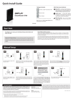


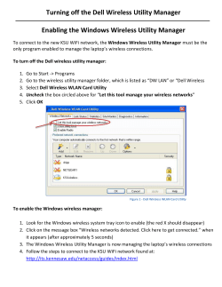

© Copyright 2026