
PeriScope Central Management System (CMS) 5.0 Administrator’s Guide
PeriScope Central Management System (CMS) 5.0 Administrator’s Guide Central Management and Configuration Software for Peribit Sequence Reducers and Sequence Mirrors Peribit Networks, Inc. 2300 Central Expressway Santa Clara, CA 95050 Phone: 1-866-Peribit 408-330-5600 Fax: 408-330-5601 Email: [email protected] Web: http://www.peribit.com Part number 100316 Rev. 003 Copyright PeriScope Central Management System (CMS) Administrator’s Guide © 2003-2004 Peribit Networks, Inc. All Rights Reserved. Peribit, the Peribit logo, PeriSphere, PeriScope, Molecular Sequence Reduction, MSR, Network Sequence Mirroring, NSM, Packet Flow Acceleration, PFA, Policy-Based Multipath, PBM, Sequence Reducer, SR, Sequence Mirror, SM, Sequence Reduction System, and SRS are trademarks or registered trademarks of Peribit Networks. All other products and services are trademarks, registered trademarks, service marks or registered service marks of their respective owners. U.S. GOVERNMENT RIGHTS Use, duplication, or disclosure by the U.S. Government of any of the programs included in this product shipment is subject to restrictions set forth in the Peribit Networks, Inc. SOFTWARE LICENSE AGREEMENT AND LIMITED WARRANTY and as provided in DFARS 227.7202-1(a) and 227.7202-3(a) (1995), DRAS 252.227-7013(c)(ii) (OCT 1988), FAR 12.212(a)(1995), FAR 52.227-19, or FAR 52.227-14 (ALT III), as applicable. Peribit Networks, Inc. This software product is the property of Peribit Networks, Inc. and its licensors, and is subject to the Clickwrap License Agreement accompanying this software product. By installing or using the software product, you agree to be bound to the terms of the Clickwrap License Agreement. You may not modify, translate, reverse engineer, decompile, disassemble or otherwise attempt to reconstruct or discover the source code of the software product. The Clickwrap License Agreement contains additional restrictions and disclaimers. Any use, duplication, or disclosure by the U.S government of any of the code included in this software product is subject to restrictions as set forth in the Clickwrap License Agreement accompanying this software product, and as provided in DFARS 227.7202-1(a) and 227.7202-3(a) (1995), DFARS 252.227-7013(c)(1)(ii) (OCT 1988), FAR 12.212(a) (1995), FAR 52.227-19, or FAR 52.227-14 (ALT III), as applicable. Peribit Networks, Inc., 2855 Bowers Avenue, Santa Clara, California 95051. This product includes code licensed from RSA Security, Inc. Some portions licensed from IBM are available at http://oss.software.ibm.com/icu4j/. This product includes software developed by the Apache Software Foundation (http:// www.apache.org). Copyright © 2000 The Apache Software Foundation. All rights reserved. A copy of the Apache Software License terms, restrictions and disclaimers is available at http://www.apache.org/licenses/LICENSE. This product includes software developed by the ExoLab Project (http://www.exolab.org). Copyright © 2000-2002 Intalio Inc. All rights reserved. A copy of the license terms, restrictions and disclaimers for this software is available at http://castor.exolab.org/license.html. Contents Preface . . . . . . . . . . . . . . . . . . . . . . . . . . . . . . . . . . . . . . . . . . . . . . . . . .11 Audience. . . . . . . . . . . . . . . . . . . . . . . . . . . . . . . . . . . . . . . . . . . . . . . . . . . . . . . 11 Document Contents . . . . . . . . . . . . . . . . . . . . . . . . . . . . . . . . . . . . . . . . . . . . . . 11 Document Conventions . . . . . . . . . . . . . . . . . . . . . . . . . . . . . . . . . . . . . . . . . . . 13 Typographical Conventions. . . . . . . . . . . . . . . . . . . . . . . . . . . . . . . . . . . . . . 13 Technical Support. . . . . . . . . . . . . . . . . . . . . . . . . . . . . . . . . . . . . . . . . . . . . . . . 13 Obtaining Additional Product Information . . . . . . . . . . . . . . . . . . . . . . . . . . . . 14 Chapter 1 Introduction . . . . . . . . . . . . . . . . . . . . . . . . . . . . . . . . . . . .15 About PeriScope CMS . . . . . . . . . . . . . . . . . . . . . . . . . . . . . . . . . . . . . . . . . . . 15 What’s New in Version 5.0 . . . . . . . . . . . . . . . . . . . . . . . . . . . . . . . . . . . . . . . . 16 How PeriScope CMS Works . . . . . . . . . . . . . . . . . . . . . . . . . . . . . . . . . . . . . . . 17 Understanding PeriScope CMS . . . . . . . . . . . . . . . . . . . . . . . . . . . . . . . . . . . . . 18 PeriScope CMS Support of Device Software Versions . . . . . . . . . . . . . . . . 18 Logging In to PeriScope CMS . . . . . . . . . . . . . . . . . . . . . . . . . . . . . . . . . . . 18 PeriScope CMS Web Console Interface . . . . . . . . . . . . . . . . . . . . . . . . . . . . 19 Where to Go Next. . . . . . . . . . . . . . . . . . . . . . . . . . . . . . . . . . . . . . . . . . . . . . . . 20 Chapter 2 Installing PeriScope CMS. . . . . . . . . . . . . . . . . . . . . . . . .21 System Requirements . . . . . . . . . . . . . . . . . . . . . . . . . . . . . . . . . . . . . . . . . . . . 21 Pre-Installation Tasks . . . . . . . . . . . . . . . . . . . . . . . . . . . . . . . . . . . . . . . . . . . . 22 Installing PeriScope CMS . . . . . . . . . . . . . . . . . . . . . . . . . . . . . . . . . . . . . . . . . 23 Uninstalling PeriScope CMS. . . . . . . . . . . . . . . . . . . . . . . . . . . . . . . . . . . . . 27 Logging In for the First Time. . . . . . . . . . . . . . . . . . . . . . . . . . . . . . . . . . . . . . . 27 Recommended Configuration Tasks . . . . . . . . . . . . . . . . . . . . . . . . . . . . . . . . . 31 Where to Go Next. . . . . . . . . . . . . . . . . . . . . . . . . . . . . . . . . . . . . . . . . . . . . . . . 32 Contents ■ iii Chapter 3 Managing Peribit Devices . . . . . . . . . . . . . . . . . . . . . . . . 33 Viewing Devices . . . . . . . . . . . . . . . . . . . . . . . . . . . . . . . . . . . . . . . . . . . . . . . . .33 Managing Devices . . . . . . . . . . . . . . . . . . . . . . . . . . . . . . . . . . . . . . . . . . . . . . . .36 Viewing Device Events . . . . . . . . . . . . . . . . . . . . . . . . . . . . . . . . . . . . . . . . .37 Loading Device Boot Images . . . . . . . . . . . . . . . . . . . . . . . . . . . . . . . . . . . . .38 Rolling Back Device Boot Images . . . . . . . . . . . . . . . . . . . . . . . . . . . . . . . . .40 Rebooting Devices . . . . . . . . . . . . . . . . . . . . . . . . . . . . . . . . . . . . . . . . . . . . .42 Viewing Device Configuration Summaries . . . . . . . . . . . . . . . . . . . . . . . . . .43 Analyzing Device Configurations . . . . . . . . . . . . . . . . . . . . . . . . . . . . . . . . .44 Loading Device Configurations . . . . . . . . . . . . . . . . . . . . . . . . . . . . . . . . . . .47 Rolling Back Device Configurations . . . . . . . . . . . . . . . . . . . . . . . . . . . . . . .50 Backing Up Device Configurations . . . . . . . . . . . . . . . . . . . . . . . . . . . . . . . .51 Restoring Device Configurations . . . . . . . . . . . . . . . . . . . . . . . . . . . . . . . . . .53 Retrieving Device Files . . . . . . . . . . . . . . . . . . . . . . . . . . . . . . . . . . . . . . . . .55 Applying a Registration Server Password . . . . . . . . . . . . . . . . . . . . . . . . . . .57 Putting Devices in Safe Mode . . . . . . . . . . . . . . . . . . . . . . . . . . . . . . . . . . . .59 Accessing the SRS Web Console from PeriScope CMS . . . . . . . . . . . . . . . . . .60 Exporting Community and Device Information . . . . . . . . . . . . . . . . . . . . . . . . .60 Managing PeriScope CMS Schedules . . . . . . . . . . . . . . . . . . . . . . . . . . . . . . . . .61 Managing Scheduled Tasks . . . . . . . . . . . . . . . . . . . . . . . . . . . . . . . . . . . . . .61 Exporting a Schedule Log . . . . . . . . . . . . . . . . . . . . . . . . . . . . . . . . . . . . . . .65 Chapter 4 Managing Device Configurations. . . . . . . . . . . . . . . . . . 67 Overview of Device Configurations . . . . . . . . . . . . . . . . . . . . . . . . . . . . . . . . . .67 Configuration Settings for SRS 5.0 and 4.0 Devices . . . . . . . . . . . . . . . . . . .68 Downloading Global and Partial Configurations . . . . . . . . . . . . . . . . . . . . . .71 Tracking Configuration Versions . . . . . . . . . . . . . . . . . . . . . . . . . . . . . . . . . .73 Tips for Managing Configurations . . . . . . . . . . . . . . . . . . . . . . . . . . . . . . . .73 Viewing Configurations . . . . . . . . . . . . . . . . . . . . . . . . . . . . . . . . . . . . . . . . . . .74 Managing Configurations . . . . . . . . . . . . . . . . . . . . . . . . . . . . . . . . . . . . . . . . . .75 Extracting Configurations . . . . . . . . . . . . . . . . . . . . . . . . . . . . . . . . . . . . . . .75 Duplicating Configurations . . . . . . . . . . . . . . . . . . . . . . . . . . . . . . . . . . . . . .77 Creating New Configurations with Factory Defaults . . . . . . . . . . . . . . . . . . .78 Comparing Configurations . . . . . . . . . . . . . . . . . . . . . . . . . . . . . . . . . . . . . .80 Displaying Configurations . . . . . . . . . . . . . . . . . . . . . . . . . . . . . . . . . . . . . . .81 Viewing Configuration History . . . . . . . . . . . . . . . . . . . . . . . . . . . . . . . . . . .82 iv ■ Peribit Central Management System Administrator’s Guide Deleting Configurations . . . . . . . . . . . . . . . . . . . . . . . . . . . . . . . . . . . . . . . . 82 Defining Configuration Settings . . . . . . . . . . . . . . . . . . . . . . . . . . . . . . . . . . . . 83 Configuring Device Settings . . . . . . . . . . . . . . . . . . . . . . . . . . . . . . . . . . . . . . . 87 Configuring Device Addresses . . . . . . . . . . . . . . . . . . . . . . . . . . . . . . . . . . . 88 Configuring Time Zone Settings . . . . . . . . . . . . . . . . . . . . . . . . . . . . . . . . . . 89 Configuring the ARP Table . . . . . . . . . . . . . . . . . . . . . . . . . . . . . . . . . . . . . . 90 Advertising Reduction Subnets . . . . . . . . . . . . . . . . . . . . . . . . . . . . . . . . . . . 91 Defining Outbound QoS Exclusions . . . . . . . . . . . . . . . . . . . . . . . . . . . . . . . 93 Adding Static Routes . . . . . . . . . . . . . . . . . . . . . . . . . . . . . . . . . . . . . . . . . . . 94 Configuring Router Polling . . . . . . . . . . . . . . . . . . . . . . . . . . . . . . . . . . . . . 96 Configuring Multi-Path Addresses . . . . . . . . . . . . . . . . . . . . . . . . . . . . . . . . 98 Configuring Basic Setup Parameters . . . . . . . . . . . . . . . . . . . . . . . . . . . . . . . . 100 Configuring the Interface Settings. . . . . . . . . . . . . . . . . . . . . . . . . . . . . . . . 100 Configuring NTP . . . . . . . . . . . . . . . . . . . . . . . . . . . . . . . . . . . . . . . . . . . . 103 Enabling SNMP . . . . . . . . . . . . . . . . . . . . . . . . . . . . . . . . . . . . . . . . . . . . . 104 Enabling Syslog Reporting . . . . . . . . . . . . . . . . . . . . . . . . . . . . . . . . . . . . . 105 Configuring Dynamic Local Routes . . . . . . . . . . . . . . . . . . . . . . . . . . . . . . 107 Enabling Route-Based Router Balancing . . . . . . . . . . . . . . . . . . . . . . . . . . 109 Designating a Registration Server . . . . . . . . . . . . . . . . . . . . . . . . . . . . . . . 111 Generating NetFlow Records . . . . . . . . . . . . . . . . . . . . . . . . . . . . . . . . . . . 112 Configuring AAA Settings . . . . . . . . . . . . . . . . . . . . . . . . . . . . . . . . . . . . . . . . 113 Selecting Authentication Methods. . . . . . . . . . . . . . . . . . . . . . . . . . . . . . . . 114 Enabling Authorization Checking . . . . . . . . . . . . . . . . . . . . . . . . . . . . . . . . 116 Defining RADIUS Servers . . . . . . . . . . . . . . . . . . . . . . . . . . . . . . . . . . . . . 117 Defining Local Users. . . . . . . . . . . . . . . . . . . . . . . . . . . . . . . . . . . . . . . . . . 119 Securing Operator Access . . . . . . . . . . . . . . . . . . . . . . . . . . . . . . . . . . . . . 121 Securing Front Panel Access . . . . . . . . . . . . . . . . . . . . . . . . . . . . . . . . . . . . 122 Configuring Application Settings . . . . . . . . . . . . . . . . . . . . . . . . . . . . . . . . . . 123 Default Application Definitions for SRS 5.0 Devices. . . . . . . . . . . . . . . . . 124 Configuring Application Definitions. . . . . . . . . . . . . . . . . . . . . . . . . . . . . . 125 Testing New Application Definitions . . . . . . . . . . . . . . . . . . . . . . . . . . . . . 129 Configuring Reduction Settings . . . . . . . . . . . . . . . . . . . . . . . . . . . . . . . . . . . . 130 Configuring Endpoints for Reduction Tunnels . . . . . . . . . . . . . . . . . . . . . . 130 Reducing and Monitoring Applications . . . . . . . . . . . . . . . . . . . . . . . . . . . 132 Configuring Remote Routes . . . . . . . . . . . . . . . . . . . . . . . . . . . . . . . . . . . . 134 Configuring Load Balancing Policies . . . . . . . . . . . . . . . . . . . . . . . . . . . . . 135 Contents ■ v Configuring Default Assemblers . . . . . . . . . . . . . . . . . . . . . . . . . . . . . . . . .137 Defining Preferred Assemblers . . . . . . . . . . . . . . . . . . . . . . . . . . . . . . . . . .139 Configuring Tunnel Mode Settings . . . . . . . . . . . . . . . . . . . . . . . . . . . . . . .141 Configuring QoS Settings . . . . . . . . . . . . . . . . . . . . . . . . . . . . . . . . . . . . . . . . .143 Using Outbound QoS to Enhance Performance . . . . . . . . . . . . . . . . . . . . . .143 Understanding Outbound QoS . . . . . . . . . . . . . . . . . . . . . . . . . . . . . . . . . . .144 Traffic Classes and Bandwidths. . . . . . . . . . . . . . . . . . . . . . . . . . . . . . . .145 QoS Templates and Endpoints . . . . . . . . . . . . . . . . . . . . . . . . . . . . . . . . .146 WAN Circuit Speeds and Router Overhead . . . . . . . . . . . . . . . . . . . . . .146 Dedicated and Oversubscribed WANs . . . . . . . . . . . . . . . . . . . . . . . . . .148 Direct Setup Versus Wizard Configuration Results . . . . . . . . . . . . . . . .149 Class Priorities and Excess Bandwidth Allocation . . . . . . . . . . . . . . . . .152 ToS/DSCP Prioritization . . . . . . . . . . . . . . . . . . . . . . . . . . . . . . . . . . . . .154 Unadvertised Subnets. . . . . . . . . . . . . . . . . . . . . . . . . . . . . . . . . . . . . . . .154 Procedure for Configuring Outbound QoS Policies . . . . . . . . . . . . . . . .154 Using the Outbound QoS Setup Wizard . . . . . . . . . . . . . . . . . . . . . . . . . . . .156 Defining Outbound QoS Settings by Endpoint. . . . . . . . . . . . . . . . . . . . . . .162 Defining Traffic Classes . . . . . . . . . . . . . . . . . . . . . . . . . . . . . . . . . . . . . . . .165 Defining Outbound QoS Templates . . . . . . . . . . . . . . . . . . . . . . . . . . . . . . .166 Defining Outbound QoS Endpoints . . . . . . . . . . . . . . . . . . . . . . . . . . . . . . .168 Changing Outbound ToS/DSCP Values . . . . . . . . . . . . . . . . . . . . . . . . . . . .171 Starting and Stopping Outbound QoS . . . . . . . . . . . . . . . . . . . . . . . . . . . . .174 Configuring Inbound QoS Policies. . . . . . . . . . . . . . . . . . . . . . . . . . . . . . . .175 Configuring Packet Flow Acceleration . . . . . . . . . . . . . . . . . . . . . . . . . . . . . . .177 Overview of Packet Flow Acceleration . . . . . . . . . . . . . . . . . . . . . . . . . . . .178 Flow Pipelining . . . . . . . . . . . . . . . . . . . . . . . . . . . . . . . . . . . . . . . . . . . .178 Fast Connection Setup . . . . . . . . . . . . . . . . . . . . . . . . . . . . . . . . . . . . . . .180 Active Flow Pipelining . . . . . . . . . . . . . . . . . . . . . . . . . . . . . . . . . . . . . .181 Forward Error Correction. . . . . . . . . . . . . . . . . . . . . . . . . . . . . . . . . . . . .182 Enabling Acceleration by Endpoint . . . . . . . . . . . . . . . . . . . . . . . . . . . . . . .182 Enabling Packet Flow Acceleration by Application. . . . . . . . . . . . . . . . . . .187 Enabling Flow Pipelining by Application . . . . . . . . . . . . . . . . . . . . . . . .187 Enabling Fast Connection Setup by Application . . . . . . . . . . . . . . . . . . .188 Enabling Active Flow Pipelining by Application . . . . . . . . . . . . . . . . . .190 Configuring Advanced Setup Parameters . . . . . . . . . . . . . . . . . . . . . . . . . . . . .191 Configuring the Community Topology . . . . . . . . . . . . . . . . . . . . . . . . . . . .191 vi ■ Peribit Central Management System Administrator’s Guide Configuring Source/Destination Filters. . . . . . . . . . . . . . . . . . . . . . . . . . . . 194 Defining the Prime Time . . . . . . . . . . . . . . . . . . . . . . . . . . . . . . . . . . . . . . . 196 Configuring Packet Interception . . . . . . . . . . . . . . . . . . . . . . . . . . . . . . . . . 198 Configuring Packet Interception for Off-Path Peribit Devices. . . . . . . . 199 RIP Router/Switch Configuration Commands . . . . . . . . . . . . . . . . . . . . 202 WCCP Router Configuration Commands. . . . . . . . . . . . . . . . . . . . . . . . 206 External Policy-Based Router Commands . . . . . . . . . . . . . . . . . . . . . . . 207 Alternatives to Packet Interception. . . . . . . . . . . . . . . . . . . . . . . . . . . . . 208 Configuring Policy-Based Multi-Path . . . . . . . . . . . . . . . . . . . . . . . . . . . . . . . 210 Procedure for Configuring Multi-Path . . . . . . . . . . . . . . . . . . . . . . . . . . . . 211 Enabling Policy-Based Multi-Path . . . . . . . . . . . . . . . . . . . . . . . . . . . . . . . 212 Defining Multi-Path Templates . . . . . . . . . . . . . . . . . . . . . . . . . . . . . . . . . . 213 Defining Multi-Path Endpoints . . . . . . . . . . . . . . . . . . . . . . . . . . . . . . . . . . 215 Configuring Routers to Support Multi-Path . . . . . . . . . . . . . . . . . . . . . . . . 218 Configuring IPSec . . . . . . . . . . . . . . . . . . . . . . . . . . . . . . . . . . . . . . . . . . . . . . 220 Default IPSec Policy . . . . . . . . . . . . . . . . . . . . . . . . . . . . . . . . . . . . . . . . . . 220 IPSec Implementation Details . . . . . . . . . . . . . . . . . . . . . . . . . . . . . . . . . . . 221 Procedure for Configuring IPSec Policies. . . . . . . . . . . . . . . . . . . . . . . . . . 222 Defining IPSec Settings by Endpoint . . . . . . . . . . . . . . . . . . . . . . . . . . . . . 222 Defining IPSec Templates . . . . . . . . . . . . . . . . . . . . . . . . . . . . . . . . . . . . . . 224 Defining the Default IPSec Policy. . . . . . . . . . . . . . . . . . . . . . . . . . . . . . . . 226 Adding CLI Commands to Configurations . . . . . . . . . . . . . . . . . . . . . . . . . . . 228 Chapter 5 Automatic Deployment of Peribit Devices . . . . . . . . . .229 About Automatic Deployment . . . . . . . . . . . . . . . . . . . . . . . . . . . . . . . . . . . . . 229 Configuring Auto-Deployment . . . . . . . . . . . . . . . . . . . . . . . . . . . . . . . . . . . . 230 Auto-Deployment Procedure . . . . . . . . . . . . . . . . . . . . . . . . . . . . . . . . . . . . 230 Defining Deployment Groups . . . . . . . . . . . . . . . . . . . . . . . . . . . . . . . . . . . 231 Defining Deployment Records . . . . . . . . . . . . . . . . . . . . . . . . . . . . . . . . . . 233 Viewing the Auto-Deployment Status. . . . . . . . . . . . . . . . . . . . . . . . . . . . . 235 Configuring License Management . . . . . . . . . . . . . . . . . . . . . . . . . . . . . . . . . . 237 Licensing Procedure . . . . . . . . . . . . . . . . . . . . . . . . . . . . . . . . . . . . . . . . . . 237 Importing and Validating RTUs . . . . . . . . . . . . . . . . . . . . . . . . . . . . . . . . . 238 Generating and Applying Licenses . . . . . . . . . . . . . . . . . . . . . . . . . . . . . . . 240 Viewing the License Status . . . . . . . . . . . . . . . . . . . . . . . . . . . . . . . . . . . . . 243 Contents ■ vii Chapter 6 Monitoring Community and Device Performance . . . 245 Viewing and Printing Reports . . . . . . . . . . . . . . . . . . . . . . . . . . . . . . . . . . . . . .245 Configuring the My Peribit Page. . . . . . . . . . . . . . . . . . . . . . . . . . . . . . . . . . . .246 Viewing Reports on the Monitor Page . . . . . . . . . . . . . . . . . . . . . . . . . . . . . . .249 Percentage of Data Reduction Statistics . . . . . . . . . . . . . . . . . . . . . . . . . . . . . .250 Outbound QoS Statistics . . . . . . . . . . . . . . . . . . . . . . . . . . . . . . . . . . . . . . . . . .255 Inbound QoS Statistics . . . . . . . . . . . . . . . . . . . . . . . . . . . . . . . . . . . . . . . . . . .259 Flow Pipelining and Active Flow Pipelining Statistics . . . . . . . . . . . . . . . . . . .262 Fast Connection Setup Statistics . . . . . . . . . . . . . . . . . . . . . . . . . . . . . . . . . . . .264 Packet Size Distribution Statistics . . . . . . . . . . . . . . . . . . . . . . . . . . . . . . . . . . .266 Top Traffic Statistics . . . . . . . . . . . . . . . . . . . . . . . . . . . . . . . . . . . . . . . . . . . . .267 Monitoring Tunnel Status . . . . . . . . . . . . . . . . . . . . . . . . . . . . . . . . . . . . . . . . .269 Chapter 7 PeriScope CMS Setup and Administration . . . . . . . . . 273 Changing User Passwords . . . . . . . . . . . . . . . . . . . . . . . . . . . . . . . . . . . . . . . .273 Defining the Default PeriScope CMS Home Page . . . . . . . . . . . . . . . . . . . . . .274 Viewing Logged In Users . . . . . . . . . . . . . . . . . . . . . . . . . . . . . . . . . . . . . . . . .275 Administering Peribit Devices. . . . . . . . . . . . . . . . . . . . . . . . . . . . . . . . . . . . . .276 Managing Communities . . . . . . . . . . . . . . . . . . . . . . . . . . . . . . . . . . . . . . . .276 Uploading an SRS Boot Image . . . . . . . . . . . . . . . . . . . . . . . . . . . . . . . . . .279 Generating a Diagnostic File . . . . . . . . . . . . . . . . . . . . . . . . . . . . . . . . . . . .280 Administering PeriScope CMS . . . . . . . . . . . . . . . . . . . . . . . . . . . . . . . . . . . . .281 Selecting the Reporting Mode . . . . . . . . . . . . . . . . . . . . . . . . . . . . . . . . . . .281 Defining PeriScope CMS User Accounts . . . . . . . . . . . . . . . . . . . . . . . . . .283 Controlling Client Device Access to PeriScope CMS . . . . . . . . . . . . . . . . .285 Defining the Session Timeout. . . . . . . . . . . . . . . . . . . . . . . . . . . . . . . . . . . .286 Configuring FTP Server Parameters . . . . . . . . . . . . . . . . . . . . . . . . . . . . . .287 Enabling Syslog Reporting . . . . . . . . . . . . . . . . . . . . . . . . . . . . . . . . . . . . .288 Entering a Permanent License Key . . . . . . . . . . . . . . . . . . . . . . . . . . . . . . .289 Stopping and Starting the Scheduler . . . . . . . . . . . . . . . . . . . . . . . . . . . . . .290 Changing the Web Server Port . . . . . . . . . . . . . . . . . . . . . . . . . . . . . . . . . .291 Configuring Data Collection and Retention . . . . . . . . . . . . . . . . . . . . . . . . .292 Backing Up and Restoring the Database . . . . . . . . . . . . . . . . . . . . . . . . . . .294 Manual Database Backups . . . . . . . . . . . . . . . . . . . . . . . . . . . . . . . . . . . .294 Automatic Database Backups . . . . . . . . . . . . . . . . . . . . . . . . . . . . . . . . .294 Purging Temporary Java Files . . . . . . . . . . . . . . . . . . . . . . . . . . . . . . . . . . .295 viii ■ Peribit Central Management System Administrator’s Guide Appendix A PeriScope CMS Licenses . . . . . . . . . . . . . . . . . . . . . .297 Appendix B Device Events . . . . . . . . . . . . . . . . . . . . . . . . . . . . . . .299 Appendix C Understanding Exported Data Results . . . . . . . . . . .303 NetFlow Version 5 Export . . . . . . . . . . . . . . . . . . . . . . . . . . . . . . . . . . . . . . . . 303 General Device Information . . . . . . . . . . . . . . . . . . . . . . . . . . . . . . . . . . . . . . . 305 System Session Statistics . . . . . . . . . . . . . . . . . . . . . . . . . . . . . . . . . . . . . . . . . 306 Reduction Session Statistics . . . . . . . . . . . . . . . . . . . . . . . . . . . . . . . . . . . . . . . 309 Application Session Statistics. . . . . . . . . . . . . . . . . . . . . . . . . . . . . . . . . . . . . . 310 Bandwidth Management Statistics . . . . . . . . . . . . . . . . . . . . . . . . . . . . . . . . . . 311 Inbound Traffic By Port Statistics . . . . . . . . . . . . . . . . . . . . . . . . . . . . . . . . . . 312 Appendix D Common Application Port Numbers . . . . . . . . . . . . .313 Glossary . . . . . . . . . . . . . . . . . . . . . . . . . . . . . . . . . . . . . . . . . . . . . . . .315 Index . . . . . . . . . . . . . . . . . . . . . . . . . . . . . . . . . . . . . . . . . . . . . . . . . . .319 Contents ■ ix x ■ Peribit Central Management System Administrator’s Guide Preface Welcome to the PeriScope™ Central Management System (CMS) — a powerful management and configuration tool for Peribit Sequence Reducer™ and Sequence Mirror™ devices. PeriScope CMS manages the SR-20™, SR-50™, SR-55™, SR-80™, SR-100™ and SM-500™ Peribit devices. This section describes the audience, organization, and typographical conventions used in this manual. Audience This manual is intended for administrators who configure and manage Peribit devices, for network administrators who install and use PeriScope CMS, and for network managers who monitor the performance of the Peribit devices. Readers are assumed to be familiar with their network architecture and devices, and can perform basic network configuration procedures. Document Contents ■ Chapter 1, “Introduction” This chapter provides an overview of PeriScope CMS, and describes the new features in this release. ■ Chapter 2, “Installing PeriScope CMS” This chapter describes how to install the PeriScope CMS software. ■ Chapter 3, “Managing Peribit Devices” This chapter describes how to centrally manage devices in a community by performing such tasks as loading new configurations and SRS™ boot images on selected devices. It also describes how to use the scheduler to manage scheduled tasks. ■ Chapter 4, “Managing Device Configurations” This chapter describes how to create and maintain global and partial configurations in PeriScope CMS. Preface ■ 11 Document Contents ■ Chapter 5, “Automatic Deployment of Peribit Devices” This chapter describes how to configure new Peribit devices automatically, and how to distribute permanent licenses to devices that have evaluation licenses. ■ Chapter 6, “Monitoring Community and Device Performance” This chapter describes how to monitor the percentage of data reduction, outbound bandwidth management by traffic class, and reduction tunnel status for the devices in each community. ■ Chapter 7, “PeriScope CMS Setup and Administration” This chapter describes PeriScope CMS administration tasks, such as importing communities and defining user accounts. ■ Appendix A, “PeriScope CMS Licenses” This appendix describes the evaluation and permanent licenses for PeriScope CMS. ■ Appendix B, “Device Events” This appendix describes the critical- and error-level Syslog messages generated by the Peribit devices and displayed in the Devices page as “events.” It also describes the appropriate action to take if a device encounters one of these events. ■ Appendix C, “Understanding Exported Data Results” This appendix describes the contents of the statistics file that PeriScope CMS can retrieve from a device. ■ Appendix D, “Common Application Port Numbers” This appendix lists common application port numbers, as listed by the Internet Assigned Numbers Authority (IANA). ■ Glossary The glossary includes definitions of networking terms as well as terms specific to Peribit devices and PeriScope CMS. 12 ■ Peribit Central Management System Administrator’s Guide Document Conventions Document Conventions This section describes conventions used throughout this manual. Typographical Conventions Table 1 lists the typographical conventions used throughout this manual. Table 1 Typographical Conventions Convention Meaning Example boldface Names of buttons or keys you should press. Click Submit. courier font Text that you enter from the keyboard. Enter the following command: a:\setup Angle brackets Variables that you must substitute another value for. set ip <Peribit device’s IP address> italics Names of manuals, directories, files, or Uniform Resource Locators (URLs). The address of Peribit’s web site is http://www.peribit.com. Technical Support Peribit's commitment to create products and services that enable our customer's success is reflected in our Technical Assistance Center (TAC), and our comprehensive support programs. For technical support with Peribit products, use the following methods: ■ Our Customer Support Extranet: a. Go to http://www.peribit.com/support b. Click Customer login. c. Enter your user name and password. If you have not received your user name and password, please send email to [email protected]. ■ Our toll-free telephone support line: Call +1-866-Peribit (+1-866-737-4248), or +1-408-330-5600 and follow the prompt for Peribit Support. Preface ■ 13 Obtaining Additional Product Information Obtaining Additional Product Information In addition to this PeriScope Central Management System Administrator’s Guide, refer to the Sequence Reducer/Sequence Mirror Operator’s Guide and the Quick Start cards for product information. The printed Quick Start cards are enclosed with the product. Also refer to the PeriScope CMS 5.0 Release Notes document enclosed with the product. For additional product information, please visit our web site at http://www.peribit.com. 14 ■ Peribit Central Management System Administrator’s Guide Chapter 1 Introduction This chapter introduces the PeriScope Central Management System (CMS) and covers the following topics: ■ “About PeriScope CMS” in the next section ■ “What’s New in Version 5.0” on page 16 ■ “How PeriScope CMS Works” on page 17 ■ “Understanding PeriScope CMS” on page 18 About PeriScope CMS PeriScope CMS provides easy and extensive central configuration and management for Peribit Sequence Reducer and Sequence Mirror devices in geographically dispersed locations. PeriScope CMS can manage up to 2000 devices in multiple communities. PeriScope CMS offers the following benefits: ■ Cost effective — PeriScope CMS reduces the cost of ownership for Peribit devices by creating a single location from which to manage all devices and leverage configurations on devices already deployed in the network. ■ Eases configuration — Using PeriScope CMS, you can quickly and easily configure tens or hundreds of newly deployed Peribit devices, modify the configuration of already deployed devices, and view and manage the newly created WAN capacity generated by Peribit’s Molecular Sequence Reduction (MSR)™ and Network Sequence Mirroring (NSM)™ technology. ■ Simplifies software deployment — PeriScope CMS dramatically simplifies the configuration and management of software upgrades. From a single location, and in a single operation, you can upgrade all devices in the same community to a new software version. ■ Creates global policies — PeriScope CMS allows network managers to centrally manage and modify global and device-specific configuration settings on all Peribit devices. Global settings include basic and advanced setup options, such as for NTP and SNMP, authentication settings, application definitions, outbound QoS settings, and the applications being reduced, monitored, and accelerated. ■ Schedules all tasks —Using PeriScope CMS, you can schedule all device management tasks to be performed at the optimal time for the individual location. Chapter 1 Introduction ■ 15 What’s New in Version 5.0 ■ Centrally views all data reduction results — PeriScope CMS provides a single, clear window into the performance of Peribit devices around the globe. It presents historical per-tunnel and per-application data reduction statistics for each device. ■ Centrally views global device and tunnel status — Using PeriScope CMS, you can immediately view the status of each deployed device and all reduction tunnels. All features are available through the PeriScope CMS Web console, which is a Web-based graphical user interface. Up to 50 users can access the Web console simultaneously. You can control access to PeriScope CMS with user accounts and passwords, as well as access control lists. What’s New in Version 5.0 PeriScope CMS 5.0 has the following new features: ■ Supports Peribit devices running SRS 4.x and SRS 5.x. ■ Almost all SRS configuration settings can now be managed through the PeriScope CMS Web console, including device-specific settings, such as IP addresses, time zones, and local routes. New partial configurations can be defined for Multi-Path, IPSec, and Device Settings (device-specific settings), and partial configurations can now be extracted from a device. ■ Auto-deployment lets you automatically download configurations and software to a new device when it is first installed. Remote personnel can simply connect the cables and apply power, and normal operation will begin without further intervention. ■ License management lets you generate and download permanent licenses in bulk to all new devices, or to any device that has an evaluation license. ■ The new My Peribit page lets each user create a customized mix of charts that depict the overall performance of the Peribit devices in one or all communities. ■ New monitoring reports are included for Flow Pipelining/AFP, Fast Connection Setup, and Packet Size Distribution. Extended reporting periods have been added (such as Last 7 Days and Last 6 Months), and users can now enter specific date ranges. ■ High Performance reporting mode generates reports from a database built by periodic polling of SRS 5.0 devices, and provides the new reports and reporting periods. Compatibility Mode lets you use CMS 4.0 reports until all devices are upgraded to SRS 5.0. 16 ■ Peribit Central Management System Administrator’s Guide How PeriScope CMS Works ■ The Windows server where you install PeriScope CMS server can be used as a Network Time Protocol (NTP) server for Peribit clients. Using an NTP server ensures the accuracy of hourly statistics. ■ The Devices page indicates which Peribit devices are using Network Sequence Mirroring (NSM), IPSec, Multi-Path, and each type of packet interception. Also, indicates which devices are NOT using an NTP server. How PeriScope CMS Works PeriScope CMS is deployed on a single Microsoft Windows Server 2000 or Windows Server 2003 server in your network (Figure 1-1). PeriScope CMS includes a Web server that can be accessed by multiple remote Web consoles using secure Web access. A PeriScope CMS Web console is a workstation in your network that supports the Microsoft Internet Explorer 5.5 or 6.0 Web browser. You can access the Web by directing the browser to the IP address or host name of the PeriScope CMS server (to use the host name, the host name must have a DNS entry.) Figure 1-1 shows a logical flow of the communication between the Peribit devices, a PeriScope CMS server, and the PeriScope CMS Web consoles. Configuration data between the Peribit devices and the PeriScope CMS server is securely transmitted via a proprietary protocol. Monitoring data is collected from the Peribit devices in clear text (compressed). Data between the PeriScope CMS server and the Web consoles is securely transmitted via HTTPS. Peribit Peribit Protocol HTTPS PeriScope CMS Web Consoles Peribit PeriScope CMS Server Peribit Figure 1-1 PeriScope CMS Communication Chapter 1 Introduction ■ 17 Understanding PeriScope CMS Understanding PeriScope CMS The following sections provide general information about PeriScope CMS. ■ “PeriScope CMS Support of Device Software Versions” in the next section. ■ “Logging In to PeriScope CMS” on page 18. ■ “PeriScope CMS Web Console Interface” on page 19. PeriScope CMS Support of Device Software Versions PeriScope CMS 5.0 manages Peribit devices running SRS version 4.0 and greater. Devices running SRS versions prior to 4.0 are displayed in some Web console pages (such as the Devices page), but they cannot be managed through PeriScope CMS. Logging In to PeriScope CMS When you log in to the PeriScope CMS Web console for the first time, you must specify the user name “root” and a default password. The root user account provides access to all PeriScope CMS functions. This level of access is known as Admin access. With Admin access, you can create up to 49 other user accounts and specify the level of access for each user, as described in “Defining PeriScope CMS User Accounts” on page 283. Up to 50 users can access the Web console at the same time. If two or more users modify the same settings concurrently, the last set of saved changes is used. To log out of the Web console, click LOGOUT in the menu frame of any page. Users are logged out automatically if their sessions are inactive for the session timeout time (default is 30 minutes). Note: If you close the Web browser without logging out, your session remains open until the session timeout time expires. 18 ■ Peribit Central Management System Administrator’s Guide Understanding PeriScope CMS PeriScope CMS Web Console Interface The menu frame of the PeriScope CMS Web console (Figure 1-2) identifies the user account used to log in and provides the following links: ■ MY PERIBIT — Select and view a personalized set of performance charts specific to the user account. ■ MONITOR — Monitor tunnel status and performance statistics. ■ MANAGEMENT — Manage devices, configurations, automatic deployment, and scheduled tasks. ■ CMS SETUP — Administer PeriScope CMS, such as add and delete user accounts, and import communities. ■ ABOUT — View PeriScope CMS server address, software version, and license information. ■ ■ — Open a PDF version of this manual. LOGOUT — Log out of the PeriScope CMS Web console. Menu Frame Data Frame Left-hand navigation frame About Window Figure 1-2 PeriScope CMS Web Console Interface Chapter 1 Introduction ■ 19 Where to Go Next The left-hand navigation frame provides various sub-menu items, and the data frame displays the Peribit device monitoring and configuration data. Where to Go Next You are ready to install the PeriScope CMS software. Proceed to “Installing PeriScope CMS” on page 21. 20 ■ Peribit Central Management System Administrator’s Guide Chapter 2 Installing PeriScope CMS This chapter describes the installation procedure for the PeriScope Central Management System (CMS) and covers the following topics: ■ “System Requirements” in the next section ■ “Pre-Installation Tasks” on page 22 ■ “Installing PeriScope CMS” on page 23 ■ “Logging In for the First Time” on page 27 ■ “Recommended Configuration Tasks” on page 31 System Requirements Verify that the designated PeriScope CMS server meets or exceeds the following hardware and software requirements: NOTE: Peribit Networks strongly recommends installing PeriScope CMS on a dedicated server. The server should not be used for any other applications. The installation optimizes some network parameters for PeriScope CMS, which should not noticeably affect the system. ■ Microsoft Windows Server 2003, or a Windows Server 2000 with Service Pack 3 ■ Table 2-1 shows the recommended and minimum CPU, memory, and disk space requirements for each range of Peribit devices being managed. These estimates assume a dedicated server with high speed drives, and a 30-minute polling interval. Table 2-1 CPU, Memory, and Disk Space Requirements Devices Pentium 4 CPU (GHz) RAM (GB) Estimated Disk Space (GB) Under 100 2.0+ (min. 1.8) 1.0 (min. 768 MB) 40+ (min. 40) 100 to 500 2.8+ (min. 2.0) 1.5 (min. 1.0) 60+ (min. 40) 500 to 1000 3.0+ (min. 2.8) 2.0 (min. 1.5) 80+ (min. 60) 1000 to 1500 3.2+ (min. 3.0) 3.0 (min. 2.0) 100+ (min. 80) 1500 to 2000 3.2+ dual CPU (min. 3.2) 4.0 (min. 3.0) 120+ (min. 100) Chapter 2 Installing PeriScope CMS ■ 21 Pre-Installation Tasks ■ CD-ROM drive ■ Video display with 1024 x 768 resolution ■ 10/100 Ethernet Network Interface Controller (NIC) ■ A user account with administrator privileges (to perform the installation) ■ Microsoft FTP Server installed and running, with an “anonymous” or password-protected user account that has read/write access to the FTP home directory Pre-Installation Tasks Complete all of the following pre-installation tasks: ❑ Verify that the TEMP environment variable for the system account is set to an NTFS drive with 100 MB of free disk space for the temporary files. NOTE: An error occurs if the disk specified by TEMP has insufficient space, even if you install PeriScope CMS on a separate disk with sufficient free space. ❑ Verify that the system date, time, and time zone are accurate for your location. In addition to the time zone setting in the Windows Date/Time properties dialog box, check the time zone environment variable. Refer to your Microsoft Windows documentation for more information. ❑ Determine if port 443 on the server is already used by IIS (the Windows Web server), or any other server. Port 443 is the default port used by the PeriScope CMS Web server. If another server uses port 443, disable the server or specify port 8443 for the PeriScope CMS Web server during installation. Port 443 or 8443 is required to support auto-deployment of Peribit devices. ❑ Verify that ports 443 (TCP) and 3578 (TCP and UDP) are not blocked by firewalls or other devices. PeriScope CMS uses these ports to communicate with the Peribit devices. ❑ Determine if the Sun™ Microsystems™ Java™ Runtime Environment (JRE™), which is a component of the Java 2 Platform, Standard Edition (J2SE™), is on your system. If JRE version 1.4.2 is not present, the PeriScope CMS installation wizard will install it. ❑ Reserve a static IP address for the PeriScope CMS server. 22 ■ Peribit Central Management System Administrator’s Guide Installing PeriScope CMS ❑ If the Microsoft FTP Server must be installed and running on the PeriScope CMS server. To install the FTP Server on Windows Server 2000: a. Click Start > Settings > Control Panel, and double-click Add/Remove Programs. b. Double-click Add/Remove Windows Components. c. Select Internet Information Services (IIS), and click Details. d. In the IIS window, select the check box for File Transfer Protocol Server and click OK. e. Click Next to install the service. When prompted, insert the Microsoft Windows 2000 Server CD into the CD drive. To install the FTP Server on Windows Server 2003, refer to your Windows documentation. Installing PeriScope CMS To install the PeriScope CMS software on your system: 1. Log in to the Microsoft Windows 2000 or 2003 server as a user with admin- istrator privileges. Next, close all windows and exit all programs, including any anti-virus programs running on the desktop. 2. If you are upgrading from CMS 4.0 to PeriScope CMS 5.0 (the upgrade cannot be reversed): NOTE: All SRS 3.0 configurations are converted to SRS 5.0-compatible configurations during the upgrade. Devices running SRS versions prior to 4.0 are listed on some PeriScope CMS pages, such as the Devices page, but they cannot be managed through PeriScope CMS. a. Stop the Peribit CMS service on the server: a. Click Start > Run, enter “services.msc” and click OK. b. In the Services window, right-click on Peribit CMS and click Stop. b. Copy the Peribit\CMS\data and Peribit\CMS\log folders to another location. Chapter 2 Installing PeriScope CMS ■ 23 Installing PeriScope CMS 3. Insert the PeriScope CMS CD into the server’s CD drive. After installation files are extracted, a welcome window for the installation wizard is displayed. If the welcome window does not appear, you can access the installation program on the CD. 4. Click Next. The PeriScope CMS license agreement appears. Read the agreement carefully. To accept the terms of the agreement, click Yes. The Customer Information window opens (Figure 2-1). Figure 2-1 Entering Customer Information 5. Enter customer information: a. Enter a user and company name if the fields are not already filled in. b. If you have a permanent license key, enter it in the License Key field. If you do not enter a license key here, you must enter it when you first log in to PeriScope CMS. For more information about licenses, refer to “PeriScope CMS Licenses” on page 297. c. Click Next. The Choose Install Type window opens (Figure 2-2). 24 ■ Peribit Central Management System Administrator’s Guide Installing PeriScope CMS Figure 2-2 Selecting the Installation Type 6. Select a Typical or Custom installation, as follows: – Click Typical to do the following: – Install the PeriScope CMS files in C:\Program Files\Peribit\CMS. – Install JRE version 1.4.2 in C:\Program Files\Java\j2rel.4.2_02 if it is not already installed on your system. – Set the Web server port to 443 (the default HTTPS port). If port 443 is currently used by IIS or some other Web server, change the port number to 8443. – To change any of the default settings, click Custom: to open the Custom Settings window (Figure 2-3). Chapter 2 Installing PeriScope CMS ■ 25 Installing PeriScope CMS Figure 2-3 Customizing PeriScope CMS Installation a. To change the locations of the CMS files, click Browse and use the Windows Explorer to navigate to the desired locations. b. If the default Web server port number (443) is already in use, enter port number 8443. If 8443 is also in use, specify a port number above 1200. Note that you cannot auto-deploy Peribit devices unless the port number is 443 or 8443. c. Click Next. 7. To change any of the previous settings, click Back. If you are satisfied with the settings, click Next to start the installation. When the installation is complete, a window displays the URL to use to access PeriScope CMS. 8. Click Finish. The restart window is displayed. You must restart the system to activate PeriScope CMS. Before restarting the system, remove any disks or CDs from the drives. 9. To restart the system, select Yes and then click Finish. 26 ■ Peribit Central Management System Administrator’s Guide Logging In for the First Time Uninstalling PeriScope CMS To uninstall PeriScope CMS, use the Microsoft Windows Add/Remove Programs function in the Control Panel. The uninstall wizard allows you to delete the PeriScope CMS data and configuration folders, which include all files related to PeriScope CMS, including the license, communities, users, and passwords. If you are removing PeriScope CMS from your system, you can safely delete these files. If the JRE was installed by the installation wizard, the uninstall wizard also lets you delete it from the system. Logging In for the First Time After installing PeriScope CMS, you must log into the Web console and perform some basic administration. You can log into the PeriScope CMS Web console from any workstation in your network. The Web console supports Microsoft Internet Explorer version 5.5 and greater. Data is securely transmitted from the PeriScope CMS server to the Web browser via HTTPS. To log in to the PeriScope CMS Web console: 1. From a workstation in your network, start your Web browser and enter the following URL: https://<IP address of the PeriScope CMS server>:<port number> Be sure to use “https” instead of “http”. Also, if you have changed the CMS Web server port number from 443 to 8443, you must include “:8443” after the IP address. For example: https://10.10.0.1:8443 If you have not changed the Web server port number from the default of 443, you can omit the colon and port number after the IP address. Chapter 2 Installing PeriScope CMS ■ 27 Logging In for the First Time 2. If you did not enter a license key during installation, the License Key page opens (Figure 2-4). Figure 2-4 Entering the License Key To obtain a license, go to http://license.peribit.com. For an evaluation license (good for 10 devices and 45 days), click Periscope CMS 5.0 Evaluation, enter the IP address of the PeriScope CMS server and other information, and click Continue. You can then copy the generated key into the License Key field here, and click Submit. 3. Depending on your Web browser settings, the Security Alert dialog box may appear. Click Yes to open the Login page (Figure 2-5). Figure 2-5 Logging In For The First Time 4. Enter the following user name and password, and click Log In. – User name: root – Password: peribit 28 ■ Peribit Central Management System Administrator’s Guide Logging In for the First Time The Change CMS Administrator Password page opens (Figure 2-6). Figure 2-6 Changing the Default Password 5. Enter a new password for the root user in the New Password and Verify New Password fields, and click Submit. The password is case-sensitive. The FTP Server page opens (Figure 2-7). Figure 2-7 Configuring FTP Server Parameters 6. The Microsoft FTP server (the “FTP Publishing Service”) must be installed and running on the PeriScope CMS server. Verify that anonymous read and write access is allowed and that the FTP root directory is correct. If anonymous access is not allowed, enter the appropriate user name and password, and click Submit. Chapter 2 Installing PeriScope CMS ■ 29 Logging In for the First Time To verify whether the FTP server allows anonymous access: a. On the Windows Control Panel, double-click Administrative Tools, and then Computer Management. b. Under Services and Applications, double-click Internet Information Services, right-click on Default FTP Settings, and select Properties. Click Security Accounts to verify that anonymous access is enabled, and click the Home Directory tab to verify that the Write check box is set. 7. A blank Communities page opens. To manage the devices in each Peribit community, you must import the communities defined on each Peribit device that acts as a registration server. For more information about registration servers, refer to “Designating a Registration Server” on page 111. If you do not yet have a registration server, you can import communities at a later time (refer to “Managing Communities” on page 276). To import communities into PeriScope CMS: a. Click Import to open the Communities > Import page (Figure 2-8). Figure 2-8 Importing Communities to PeriScope CMS b. In the Communities > Import page, enter the IP address and password of a Peribit device that acts as a primary registration server, and click Submit. c. Select the check box next to each community, click Import, and click OK. Note that the Default community on each registration server becomes “Default - <IP address>” in PeriScope CMS. 30 ■ Peribit Central Management System Administrator’s Guide Recommended Configuration Tasks The PeriScope CMS quick setup is complete. You are now ready to perform additional administrative tasks. For more information, see “Recommended Configuration Tasks” in the next section. Recommended Configuration Tasks Now that PeriScope CMS is initially configured, Peribit Networks strongly recommends performing the following tasks: ■ The clocks on all Peribit devices, including the PeriScope CMS server, should be synchronized to the same Simple Network Time Protocol (SNTP) server or server hierarchy. To use PeriScope CMS to configure an NTP server for your Peribit devices (refer to “Configuring NTP” on page 103). If you do not have an SNTP server in your network, you can use the address of the PeriScope CMS server. During installation, PeriScope CMS enables the Windows SNTP server. Be sure to verify that port 123 (UDP) is not blocked by firewalls or other devices. If you use some other SNTP server to synchronize your Peribit devices, the Windows SNTP agent on the PeriScope CMS server should be pointed to the same SNTP server. ■ If you have multiple registration servers, import the communities from each server, as described in “Managing Communities” on page 276. ■ Upload SRS boot images to the PeriScope CMS server, as described in “Uploading an SRS Boot Image” on page 279. An uploaded image can then be downloaded to selected Peribit devices. ■ Use PeriScope CMS to retrieve and analyze the differences between the configurations of selected devices. Extracted configurations can be used as a starting point in managing your device configurations. For more information about analyzing a configuration, see “Analyzing Device Configurations” on page 44. For more information about extracting a configuration, see “Extracting Configurations” on page 75. Analyzing configurations also helps you select a global configuration that can be modified and loaded on other devices. For more information about modifying and loading a configuration, see “Defining Configuration Settings” on page 83 and “Loading Device Configurations” on page 47. Chapter 2 Installing PeriScope CMS ■ 31 Where to Go Next Where to Go Next To view the devices that PeriScope CMS discovers for the Peribit Community, proceed to Chapter 3, “Managing Peribit Devices”. To create user accounts or perform additional administrative functions, proceed to Chapter 7, “PeriScope CMS Setup and Administration”. 32 ■ Peribit Central Management System Administrator’s Guide Chapter 3 Managing Peribit Devices This chapter describes how to use PeriScope CMS to centrally manage communities of Peribit devices and configure individual devices. It covers the following topics: ■ “Viewing Devices” in the next section ■ “Managing Devices” on page 36 ■ “Accessing the SRS Web Console from PeriScope CMS” on page 60 ■ “Exporting Community and Device Information” on page 60 ■ “Managing PeriScope CMS Schedules” on page 61 Viewing Devices The Devices page lets you view the devices in each community, execute tasks for selected devices, and open the SRS Web console for a specific device. To view the Peribit devices in each community: 1. Click MANAGEMENT in the menu frame. Task menu Figure 3-1 Devices Page Chapter 3 Managing Peribit Devices ■ 33 Viewing Devices 2. To view the devices in a community, select the community from the Community menu, and click Submit. From the Devices page, you can: – View the status, hardware model, software version, license, and functional properties of each device. An asterisk (*) next to the software version indicates that the device did not respond to the last query. – Click Legend to view a brief description of the icons used on the Devices page (refer to Table 3-1 for more information). – Click the column headers to change the sort. – Click Refresh to view the latest device information. The date and time of the last update is displayed at the top of the page. – Click Show Exceptions Only to view just the devices that are not responding or that have: – Events that occurred in the last 24 hours – Tasks that failed – An expired license or a registration server password different from PeriScope CMS in the Status column to view device events, as described in – Click “Viewing Device Events” on page 37. – Execute a task for one or more devices, such as loading a new boot image, as described in “Managing Devices” on page 36. – Open the SRS Web console for a device by clicking the device name, as described in “Accessing the SRS Web Console from PeriScope CMS” on page 60. – Click Export to export the device information to a CSV file, as described in “Exporting Community and Device Information” on page 60. in the SW column to view the details of failed tasks, as – Click described in “Managing PeriScope CMS Schedules” on page 61. Note: Devices with SRS versions prior to 4.0 are displayed without a check box to indicate that they cannot be managed with PeriScope CMS. 34 ■ Peribit Central Management System Administrator’s Guide Viewing Devices Table 3-1 Device Icons Icon Table Column Description Status Peribit device is up and running. Status Peribit device is operating in safe mode. Status Registration server password on the device does not match the password in PeriScope CMS. Status One or more critical- or error-level events occurred in the past 24 hours. Move the cursor over the icon to view the number of events. Click the icon to view the event details. Status Storage space on the Peribit device is low. Move the cursor over the icon to view the number of bytes remaining. Status The device is not reachable or has never responded. An asterisk (*) after the software version indicates no response to the last query. Status The device is NOT using an NTP server to maintain an accurate device time. An NTP server is recommended to ensure the accuracy of hourly reports (refer to “Configuring NTP” on page 103). Duties The device is a hub in a Hub and Spoke topology. Duties The device is a spoke in a Hub and Spoke topology. By default, a spoke reduces and assembles data only for the hub devices. Duties The device is part of a mesh topology. Duties The device is the primary registration server. Duties The device is the secondary registration server. Duties The device is a backup for one or more devices. The icon flashes when the backup device is active. Duties The device is part of a multi-node configuration. Duties Outbound Quality of Service (bandwidth management) is enabled. Duties One or more methods of Packet Flow Acceleration is enabled. Duties Network Sequence Mirroring (NSM) is enabled. Duties Policy-Based Multi-Path is enabled. Duties IPSec encryption is enabled. Chapter 3 Managing Peribit Devices ■ 35 Managing Devices Table 3-1 Device Icons (Continued) Icon Table Column Description Duties Packet interception using RIP is enabled. Duties Packet interception using WCCP is enabled. Duties Packet interception using external routing is enabled. SW One or more scheduled tasks is pending. Click the icon to view more information about the scheduled tasks SW One or more scheduled tasks has failed. Click the icon to view more information about the failed tasks. License License key has an expiration date. Move the cursor over the icon to view the number of days remaining. License Licensed throughput is exceeded. Managing Devices The following sections describe the device management tasks: ■ “Viewing Device Events” in the next section ■ “Loading Device Boot Images” on page 38. ■ “Rolling Back Device Boot Images” on page 40. ■ “Rebooting Devices” on page 42. ■ “Viewing Device Configuration Summaries” on page 43. ■ “Analyzing Device Configurations” on page 44. ■ “Loading Device Configurations” on page 47. ■ “Rolling Back Device Configurations” on page 50. ■ “Backing Up Device Configurations” on page 51 ■ “Restoring Device Configurations” on page 53 ■ “Retrieving Device Files” on page 55. ■ “Applying a Registration Server Password” on page 57. ■ “Putting Devices in Safe Mode” on page 59. 36 ■ Peribit Central Management System Administrator’s Guide Managing Devices Viewing Device Events To view the details of device events: 1. On the Devices page, select a community from the Community menu. 2. Click in the Status column to open the Events window (Figure 3-2). The event icon is displayed only if one or more critical- or error-level events occurred on the device in the past 24 hours. Figure 3-2 Viewing Device Events The Events window displays the severity level, description, and date and time of the last 20 events for the device. To update the list, click Refresh. 3. To delete all events and remove the event icon from the Devices page, click Clear Events. This also clears the events on the Peribit device. 4. To close the Events window, click Close. For a list of the possible events and recommended actions, refer to Appendix B, “Device Events.” Chapter 3 Managing Peribit Devices ■ 37 Managing Devices Loading Device Boot Images After you load an SRS boot image on the PeriScope CMS server, you can globally distribute the image to selected Peribit devices in a community. To upload a boot image, refer to “Uploading an SRS Boot Image” on page 279. Loading a boot image on a device does not affect the device configurations. All configuration information is preserved. Peribit Networks strongly recommends using the same boot image on all Peribit devices in the same community. Loading a boot image involves two tasks: ■ Load the boot image from PeriScope CMS to selected Peribit devices. ■ Reboot the Peribit devices to activate the new boot image. The reboot can be done automatically or scheduled as a separate task. When loading a boot image to multiple Peribit devices, you should schedule the reboot separately after verifying that the boot image was loaded successfully on each device. This lets you activate the new boot image on all devices simultaneously. To verify a task was successful, refer to “Managing Scheduled Tasks” on page 61. If you have any problems after upgrading to a new boot image, you can roll the boot image back to the previous version, as described in “Rolling Back Device Boot Images” in the next section. CAUTION: You can downgrade devices to a previous version of SRS. However, Peribit Networks strongly recommends that you avoid downgrading whenever possible. Downgrading may cause unpredictable behavior because the configuration and other data files were created with the later release. Monitor downgraded devices carefully. If problems occur, restore or roll back the configuration to the one used with the older boot image, if possible (refer to “Rolling Back Device Configurations” on page 50 and “Restoring Device Configurations” on page 53). To load a boot image on selected devices: 1. On the Devices page, select a community from the Community menu. 2. Select the devices where you want to load the boot image or click Select All. 3. From the Task menu, select Image > Load and click Go. 38 ■ Peribit Central Management System Administrator’s Guide Managing Devices Figure 3-3 Loading a Boot Image on Peribit devices 4. Specify the following information: Boot image Select the SRS boot image you want to load. The default naming convention of boot images is: srs<rdmbb>.<zip or bin> where: <r> is the major release number. <d> is the minor release number. <m> is the maintenance release number. <bb> is the build number. The file extension must be “zip” or “bin”. Schedule Select Load now or select Delay loading until and enter a future time and date: • Enter the time in HH:MM format (HH is 0-12 and MM is 0-59), and click AM or PM. Note that midnight can be 0:0 AM or 12:00 AM. • Enter a date in MM/DD/YYYY format or click select the month and date. Chapter 3 and Managing Peribit Devices ■ 39 Managing Devices Reboot Click the check box to reboot the device after the image is loaded. The loaded image is not activated until the device is rebooted. To schedule the reboot as a separate task, which is recommended when updating multiple devices, refer to “Rebooting Devices” on page 42. NOTE: When you reboot a device, all unsaved configuration data is lost. Downgrade Click the check box if the selected boot image is older than the current version. CAUTION: Downgrading to a previous boot image may cause unpredictable behavior and should be avoided whenever possible. 5. To review the devices you selected, click Show selected devices. 6. Click Submit to submit this task, or click Cancel. PeriScope CMS reports on whether the task was submitted successfully. To view the status of the task, refer to “Managing Scheduled Tasks” on page 61. If problems occur after upgrading to a new boot image, you can roll the boot image back to the previous version, as described in “Rolling Back Device Boot Images” in the next section. Rolling Back Device Boot Images When you load a SRS boot image from PeriScope CMS, each Peribit device retains the previous boot image. If problems occur with the new image, you can roll back to the previous version. During a rollback, each device reverts to the previous image and deletes the current image. Note: You can roll back the boot image on a device only if you loaded the boot image from PeriScope CMS. Rolling back the boot image does not affect the device configurations. All configuration information is preserved. Peribit Networks strongly recommends using the same boot image on all Peribit devices in the same community. Rolling back a boot image involves two tasks: ■ PeriScope CMS directs the specified devices to roll back to the previous image. ■ Reboot the Peribit devices to activate the rolled back boot image. The reboot can be done automatically or scheduled as a separate task. 40 ■ Peribit Central Management System Administrator’s Guide Managing Devices When rolling back the boot image on multiple Peribit devices, you should schedule the reboot separately after verifying that the rollback was successful on each device. This lets you activate the boot image on all devices simultaneously. To verify a task was successful, refer to “Managing Scheduled Tasks” on page 61. To roll back the boot image on selected devices: 1. On the Devices page, select a community from the Community menu. 2. Select the devices where you want to roll back the boot image or click Select All. 3. From the Task menu, select Image > Rollback and click Go. Figure 3-4 Rolling Back the Boot Image 4. Specify the following information: Schedule Select Roll back now or select Delay roll back until and enter a future time and date: • Enter the time in HH:MM format (HH is 0-12 and MM is 0-59), and click AM or PM. Note that midnight can be 0:0 AM or 12:00 AM. • Enter a date in MM/DD/YYYY format or click select the month and date. Chapter 3 and Managing Peribit Devices ■ 41 Managing Devices Reboot Click the check box to reboot the device after the rolled back image is loaded. The loaded image is not activated until the device is rebooted. To schedule the reboot as a separate task, which is recommended when updating multiple devices, refer to “Rebooting Devices” on page 42. NOTE: When you reboot a device, all unsaved configuration data is lost. 5. To review the devices you selected, click Show selected devices. 6. Click Submit to submit this task, or click Cancel. PeriScope CMS reports on whether the task was submitted successfully. To view the status of the task, refer to “Managing Scheduled Tasks” on page 61. Rebooting Devices You must reboot a Peribit device to activate a loaded or rolled back boot image or to reactivate data reduction on a device that is in safe mode. Note: When you reboot a device, all unsaved configuration data is lost. To reboot selected devices: 1. On the Devices page, select a community from the Community menu. 2. Select the devices that you want to reboot or click Select All. 3. From the Task menu, select Reboot and click Go. Figure 3-5 Rebooting a Device 42 ■ Peribit Central Management System Administrator’s Guide Managing Devices 4. Select Reboot now or select Delay reboot until and enter a time and date: – Enter the time in HH:MM format (HH is 0-12 and MM is 0-59), and click AM or PM. Note that midnight can be 0:0 AM or 12:00 AM. – Enter a date in MM/DD/YYYY format or click and date and select the month 5. To review the devices you selected, click Show selected devices. 6. Click Submit to submit this task, or click Cancel. PeriScope CMS reports on whether the task was submitted successfully. To view the status of the task, refer to “Managing Scheduled Tasks” on page 61. Viewing Device Configuration Summaries If you have loaded configurations to one or more Peribit devices from PeriScope CMS, you can view a summary of the last set of configurations loaded on each device. You can also verify whether a device has any unsaved settings that can be defined in a global configuration. Unsaved settings are lost when you load a global configuration. To view configuration summaries: 1. On the Devices page, select a community from the Community menu. 2. Select the devices for which you want to view a summary or click Select All. 3. From the Task menu, select Configuration > Summary and click Go. Figure 3-6 Configuration Summary Chapter 3 Managing Peribit Devices ■ 43 Managing Devices The following information is displayed for each selected device: – Name and type of the last global and partial configurations downloaded from PeriScope CMS. – Date and time the “load configuration” task was created and submitted to the scheduler. – Date and time the configuration was applied to the device. The created and applied times are different if the load task was scheduled for a future time. If no configurations have been loaded from PeriScope CMS for a device, N/A is displayed for the above fields. 4. Click Verify for a device to check for differences between the saved and running configurations. All configuration settings are saved as CLI commands. For descriptions of each CLI command, refer to the Sequence Reducer/Sequence Mirror Operator’s Guide. The Verify windows shows device-specific settings in bold italics. Colorcoded lines indicate the following: – Blue. Settings unique to the saved configuration in the left column. – Yellow. Settings unique to the running configuration in the right column. – Pink. Settings that are different between the two configurations. When you are done viewing the configuration, click Close. To capture unsaved settings, you can extract the running configuration, as described in “Extracting Configurations” on page 75. Alternatively, you can incorporate the unsaved changes in an existing configuration (refer to “Defining Configuration Settings” on page 83). Analyzing Device Configurations PeriScope CMS lets you analyze the differences between the configurations on two or more Peribit devices in a community. This is particularly useful if the devices were installed and configured without PeriScope CMS. Based on the analysis, you can eliminate unnecessary differences between devices, and extract global or partial configurations that you can load on other devices. 44 ■ Peribit Central Management System Administrator’s Guide Managing Devices To analyze configurations: 1. On the Devices page, select a community from the Community menu. 2. Select the devices you want to analyze or click Select All. 3. From the Task menu, select Configuration > Analyze and click Go. Figure 3-7 Analyzing Configurations The Configuration Analysis Results window includes the following: – Devices from which a configuration could not be retrieved – Sets of devices that have identical configurations Chapter 3 Managing Peribit Devices ■ 45 Managing Devices – Devices that have unique configurations – Comparisons of each unique pair of configurations and the number of differences between them. Note: The number of differences indicates the number of different blocks of settings, not the number of different lines. 4. To view devices by IP address, rather than by name, select IP Address from the menu at the top of the window. 5. To view or compare the settings that can be defined in a global configuration in PeriScope CMS, do one of the following. All configuration settings are saved as CLI commands. For descriptions of each CLI command, refer to the Sequence Reducer/Sequence Mirror Operator’s Guide. a. Click Set <number> to view of one of the identical configuration sets. b. Click the device name or IP address to view a unique configuration. c. Click Compare next to the two configurations you want to compare. A line-by-line comparison of the settings that can be defined in a global configuration is displayed. Color-coded lines indicate the following: – Blue. Settings unique to the configuration in the left column. – Yellow. Settings unique to the configuration in the right column. – Pink. Settings that are different between the two configurations. When you are done viewing the configurations, click Close. 6. To create a global configuration from a devices’s running configuration, click EXTRACT next to the device, enter a configuration name and description, and click Submit. Only the settings that can be defined in a global configuration in PeriScope CMS are extracted. The extracted configuration is added to the Configurations page. You can then edit the configuration and load it on selected devices, as described in “Defining Configuration Settings” on page 83, and “Loading Device Configurations” on page 47. 7. When you are done viewing the Configuration Analysis Results window, click Close. 46 ■ Peribit Central Management System Administrator’s Guide Managing Devices Loading Device Configurations PeriScope CMS lets you load a configuration on selected devices in a community. A loaded configuration can consist of a global configuration and/or one or more partial configurations. The configuration changes take effect immediately. Table 3-2 describes how global and partial configurations are processed when they are loaded on SRS 4.0 and 5.0 devices. Table 3-2 Processing of Loaded Configurations Device Version SRS 5.0 Configuration Processing • Global configuration only. The settings in the global configuration override the corresponding settings on each device. If any of the default settings in the global configuration are not changed, the corresponding settings on each device are reset to the factory defaults. • Global and partial configurations. The settings in the global configuration are overridden by the settings in the partial configurations, and the result overrides the corresponding settings on each device. Any settings in the combined global and partial configurations that are not defined are reset to the factory defaults on each device. • Partial configurations only. The settings in the partial configurations override the corresponding settings on each device. For any settings in the partial configurations that are not defined, the corresponding settings on each device are retained, provided they were saved in the startup configuration file. Device settings are replaced, not supplemented. For example, if a device has four QoS traffic classes, and you load a configuration that has two classes, the resulting device configuration will have two traffic classes, not six. Settings that can be specified only by CLI commands are retained on each device unless they are overridden by commands in the CLI section of a global configuration. SRS 4.0 Same processing as for SRS 5.0, except that loading a 4.0 global configuration affects a smaller subset of the configuration settings on each device. For example, a 4.0 global configuration cannot specify QoS endpoints, so when you load a 4.0 global configuration, the QoS endpoints defined on each device are retained. Chapter 3 Managing Peribit Devices ■ 47 Managing Devices You can preview the results for each device before submitting the task. For more information about global and partial configurations, refer to “Overview of Device Configurations” on page 67. To load a configuration: 1. On the Devices page, select a community from the Community menu. 2. Select the devices where you want to load a configuration or click Select All. 3. If you have previously loaded configurations from PeriScope CMS, check each device for unsaved configuration settings (refer to “Viewing Device Configuration Summaries” on page 43). Unsaved settings are lost when a new configuration is loaded. Note: Do not select devices running different versions of SRS. The SRS 4.x, and 5.x configuration files are not compatible. 4. From the Task menu, select Configuration > Load and click Go. Figure 3-8 Loading a Configuration 48 ■ Peribit Central Management System Administrator’s Guide Managing Devices 5. Specify the following information: Global Configuration To change all the global configuration settings on the selected devices, select a global configuration. Click History to view the selected configuration and its history of changes. To create global configurations, refer to “Managing Configurations” on page 75. To load only partial configurations, select Do not load global configuration. Partials To specify partial configurations, click Yes and select up to one of each type of partial configuration. The settings in each partial configuration replace the corresponding settings in the selected global configuration (if any) or are added directly to each device configuration. Click History to view each selected configuration and its history of changes. Schedule Select Load now or select Delay loading until and enter a future time and date: • Enter the time in HH:MM format (HH is 0-12 and MM is 0-59), and click AM or PM. Note that midnight can be 0:0 AM or 12:00 AM. • Enter a date in MM/DD/YYYY format or click select the month and date. and • To load the configuration periodically, select a recurring retrieval interval (Daily, Weekly, or Monthly). Reboot Click the check box to reboot the device after the configuration is loaded. The new configuration takes effect with or without a reboot. However, a reboot is recommended when you make substantial changes to a configuration or when you change the topology parameter. NOTE: When you reboot a device, all unsaved configuration data is lost. 6. To review the devices you selected, click Show selected devices. 7. Click Preview to view the resulting configuration for the first device. The blue text indicates the configuration settings that must be specified by CLI commands, a Device Settings partial configuration, or the SRS Web console. Click Next to preview the configuration for each selected device. To open the SRS Web console, refer to “Accessing the SRS Web Console from PeriScope CMS” on page 60. To change a global or partial configuration, refer to “Defining Configuration Settings” on page 83. Chapter 3 Managing Peribit Devices ■ 49 Managing Devices All configuration settings are saved as CLI commands. For descriptions of each CLI command, refer to the Sequence Reducer/Sequence Mirror Operator’s Guide. 8. Click Submit to submit this task, or click Cancel. PeriScope CMS reports on whether the task was submitted successfully. To view the status of the task, refer to “Managing Scheduled Tasks” on page 61. Rolling Back Device Configurations When you load a configuration on one or more Peribit devices from PeriScope CMS, each device’s previous configuration is retained in CMS. If problems occur with the new configuration, you can roll back to the previous version. Note: You can roll back the configuration on a device only if you loaded the current configuration from PeriScope CMS. To roll back the configuration on selected devices: 1. On the Devices page, select a community from the Community menu. 2. Select the devices where you want to roll back a configuration or click Select All. 3. From the Task menu, select Configuration > Rollback and click Go. Figure 3-9 Rolling Back the Configuration 4. To view the rollback configuration (if any), click Preview. 50 ■ Peribit Central Management System Administrator’s Guide Managing Devices 5. Specify the following information: Schedule Select Roll back now or select Delay loading until and enter a future time and date: • Enter the time in HH:MM format (HH is 0-12 and MM is 0-59), and click AM or PM. Note that midnight can be 0:0 AM or 12:00 AM. • Enter a date in MM/DD/YYYY format or click select the month and date. Reboot and Click the check box to reboot the device after the configuration is rolled back. The configuration takes effect with or without a reboot. However, a reboot is recommended if the rolled back configuration has substantial changes or has a different topology setting. NOTE: When you reboot a device, all unsaved configuration data is lost. 6. To review the devices you selected, click Show selected devices. 7. Click Submit to submit this task, or click Cancel. PeriScope CMS reports on whether the task was submitted successfully. To view the status of the task, refer to “Managing Scheduled Tasks” on page 61. Backing Up Device Configurations You can schedule the configuration file (startup.cfg) to be backed up periodically for each Peribit device running SRS 4.x or higher. Each configuration file is archived in the following directory on the PeriScope CMS server: <CMS file location>\data\configuration\config\device\RCS The default <CMS file location> is C:\Program Files\Peribit\CMS. The backup configuration files are archived as “Version 1.1”, “Version 1.2”, and so on. A new version is archived only if changes have occurred since the last backup. To restore an archived configuration file, refer to “Restoring Device Configurations” on page 53. To back up device configurations: 1. On the Devices page, select a community from the Community menu. 2. Select the devices you want to back up or click Select All. 3. From the Task menu, select Configuration > Backup and click Go. Chapter 3 Managing Peribit Devices ■ 51 Managing Devices Figure 3-10 Backing up Configuration Files 4. Specify the following information: Backup Select whether you want to save the running configuration before doing the backup (the default). Alternatively, you can back up the current saved configuration or the running configuration. Schedule Select Backup now or select Delay backup until and enter a future time and date: • Enter the time in HH:MM format (HH is 0-12 and MM is 0-59), and click AM or PM. Note that midnight can be 0:0 AM or 12:00 AM. • Enter a date in MM/DD/YYYY format or click select the month and date. and • To back up the configuration periodically, select a recurring retrieval interval (Daily, Weekly, or Monthly). 5. To review the devices you selected, click Show selected devices. 6. Click Submit to submit this task, or click Cancel. PeriScope CMS reports on whether the task was submitted successfully. To view the status of the task and access the backed up configuration file, refer to “Managing Scheduled Tasks” on page 61. 52 ■ Peribit Central Management System Administrator’s Guide Managing Devices Restoring Device Configurations If you periodically back up the configuration file (startup.cfg) for each Peribit device, you can restore a backup configuration at any time. Note that each backup contains device-specific settings, so it can be restored only to its original device. To back up configuration files, refer to “Backing Up Device Configurations” on page 51. To restore an archived configuration file: 1. On the Devices page, select a community from the Community menu. 2. Select one device where you want to restore the configuration. 3. From the Task menu, select Configuration > Restore and click Go. Figure 3-11 Restoring a Configuration File Chapter 3 Managing Peribit Devices ■ 53 Managing Devices 4. Specify the following information: Version Select the configuration to be restored. The most recent backup has the highest “1.n” version number. The list is empty if you have no backups for the selected device. Click VIEW to verify the settings in the selected configuration. All configuration settings are saved as CLI commands (the commands are described in the Sequence Reducer/ Sequence Mirror Operator’s Guide). Schedule Select Restore now or select Delay restore until and enter a future time and date: • Enter the time in HH:MM format (HH is 0-12 and MM is 0-59), and click AM or PM. Note that midnight can be 0:0 AM or 12:00 AM. • Enter a date in MM/DD/YYYY format or click select the month and date. and • To restore the configuration periodically, select a recurring retrieval interval (Daily, Weekly, or Monthly). Reboot Click the check box to reboot the device after the configuration is restored. The configuration takes effect with or without a reboot. However, a reboot is recommended if the restored configuration has substantial changes or has a different topology setting. NOTE: When you reboot a device, all unsaved configuration data is lost. 5. To verify the device you selected, click Show selected device. 6. Click Submit to submit this task, or click Cancel. PeriScope CMS reports on whether the task was submitted successfully. To view the status of the task, refer to “Managing Scheduled Tasks” on page 61. 54 ■ Peribit Central Management System Administrator’s Guide Managing Devices Retrieving Device Files You can schedule the following files to be retrieved periodically from selected Peribit devices: ■ Diagnostic file. Current configuration and the most recent system log and access control log. ■ System Log. Critical, error, and information messages related to the operation of the device. ■ Access Control Log. Log of each user who accessed the device in the last five days. Includes the workstation IP address for HTTPS and SSH access, and any configuration changes made by the user. ■ Monitor statistics. All performance data from last month through the hour of the retrieval. The statistics are described in Appendix C, “Understanding Exported Data Results.” ■ Flow statistics. Top traffic flows collected on the device. This file is empty if there are no top traffic statistics on the device. The monitor and flow statistics are in CSV format, and can be imported into a spreadsheet or other data analysis program. For each device, the retrieved files are compressed in ZIP or TAR file (TAR files are used only for diagnostic files). The files for each device are stored in the following directory on the PeriScope CMS server: <CMS file location>\data\download\<device ip address> The <CMS file location> is D:\Program Files\Peribit\CMS, unless it was changed during installation. Note: To retrieve device files, the Microsoft FTP server must be installed and running on the PeriScope CMS server. Also, if you retrieve device files on a recurring basis, be sure that adequate disk space is available. You can access the retrieved files from the Schedules page and download the files to the hard disk of your PeriScope CMS Web console. To view the status of the task, refer to “Managing Scheduled Tasks” on page 61. Chapter 3 Managing Peribit Devices ■ 55 Managing Devices To retrieve files from selected Peribit devices: 1. On the Devices page, select a community from the Community menu. 2. Select the devices that you want to retrieve files from or click Select All. 3. From the Task menu, select Diagnostics/Statistics and click Go. Figure 3-12 Retrieving Statistics/Diagnostic Files 4. Select the checkbox next to the files you want to retrieve. If you select the diagnostic file, the system and access control logs are included, so you do not need to select them separately. 56 ■ Peribit Central Management System Administrator’s Guide Managing Devices 5. Select Retrieve now or select Delay retrieval until and enter a time and date, and a recurring retrieval interval (optional): – Enter the time in HH:MM format (HH is 0-12 and MM is 0-59), and click AM or PM. Note that midnight can be 0:0 AM or 12:00 AM. – Enter a date in MM/DD/YYYY format or click and date. and select the month – To retrieve the selected files periodically, select a recurring retrieval interval (Hourly, Daily, Weekly, or Monthly). The hourly interval is available if only monitor and/or flow statistics are selected. 6. To review the devices you selected, click Show selected devices. 7. Click Submit to submit the task, or click Cancel. PeriScope CMS reports on whether the task was submitted successfully. To view the status of the task and access the retrieved files, refer to “Managing Scheduled Tasks” on page 61. Applying a Registration Server Password Each Peribit device accesses the registration server periodically to identify the other devices in the same community. If you change the registration server’s password, you must apply the new password to all devices in each community managed by the registration server. To change a registration server’s password, do the following: ■ Use the SRS Web console to change the password on the registration server. ■ Enter the new password in PeriScope CMS (refer to “Managing Communities” on page 276). ■ Apply the new password to the devices in each community, as described below. Note: All Peribit devices reporting to the same registration server must use the same registration server password. Chapter 3 Managing Peribit Devices ■ 57 Managing Devices To apply a new registration server password to all devices in a community: 1. On the Devices page, select a community from the Community menu. 2. Click Select All to select all devices in the community. 3. From the Task menu, select Apply password and click Go. Figure 3-13 Applying a Registration Server Password 4. Select Apply password now or select Delay until and enter a time and date: – Enter the time in HH:MM format (HH is 0-12 and MM is 0-59), and click AM or PM. Note that midnight can be 0:0 AM or 12:00 AM. – Enter a date in MM/DD/YYYY format or click and date and select the month 5. To review the devices you selected, click Show selected devices. 6. Click Submit to submit this task, or click Cancel. PeriScope CMS reports on whether the task was submitted successfully. To view the status of the task, refer to “Managing Scheduled Tasks” on page 61. 58 ■ Peribit Central Management System Administrator’s Guide Managing Devices Putting Devices in Safe Mode If you have problems with your network or a specific Peribit device, you can put the device in safe mode. In safe mode, the device is powered on and can be managed over the network, but all traffic is passed through without data reduction or assembly. Note: Putting a device in safe mode reboots the device, so any unsaved configuration data is lost. To put Peribit devices in safe mode: 1. On the Devices page, select a community from the Community menu. 2. Select the devices that you want to put in safe mode. 3. From the Task menu, select Put in ‘SAFE’ mode and click Go. Figure 3-14 Putting Peribit Devices in Safe Mode 4. To review the devices you selected, click Show selected devices. 5. Click OK to submit this task, or click Cancel. PeriScope CMS reports on whether the task was submitted successfully. To view the status of the task, refer to “Managing Scheduled Tasks” on page 61. 6. Perform the appropriate troubleshooting and diagnostics. When you are done, reboot the devices to enable data reduction (refer to “Rebooting Devices” on page 42). Chapter 3 Managing Peribit Devices ■ 59 Accessing the SRS Web Console from PeriScope CMS Accessing the SRS Web Console from PeriScope CMS You can configure individual Peribit devices by accessing the SRS Web console from PeriScope CMS. To configure a device: 1. On the Devices page, click the name of the device that you want to configure. 2. Enter the user name and password. The SRS Web console opens. 3. For complete information about configuring a device from the SRS Web console, see the Sequence Reducer/Sequence Mirror Operator’s Guide. Exporting Community and Device Information Information about the Peribit devices in a selected community can be exported to a file in comma-separated variable (CSV) format. The CSV file can then be imported into a spreadsheet program (such as Microsoft Excel) or other data evaluation program. The exported file contains the following information: ■ Community name ■ Registration server IP address ■ Date and time of the export ■ The following information for each device in the selected community: – Device name. – IP address. – Model number. – Serial number. – Local MAC address. – Remote MAC address. – License speed. – Software version. 60 ■ Peribit Central Management System Administrator’s Guide Managing PeriScope CMS Schedules To export community and device information: 1. On the Devices page, select a community from the Community menu. 2. Click Export in the upper-right corner of the page. 3. To save the file to a local hard disk, click Save and specify a file name and location. Managing PeriScope CMS Schedules The following sections describe how to use the PeriScope CMS scheduler: ■ “Managing Scheduled Tasks” on page 61 ■ “Exporting a Schedule Log” on page 65 Managing Scheduled Tasks The Schedules page lets you view all device tasks scheduled in the last 15 days, including tasks that are pending, in-process, successful, failed, or cancelled. To view tasks older than 15 days, refer to “Exporting a Schedule Log” on page 65. The following scheduling actions are available: ■ Acknowledge. Failed tasks can be acknowledged, which removes the failed task icon from the Devices page. ■ Cancel. Pending tasks can be cancelled for all or selected devices. ■ Reschedule. Failed and pending tasks can be rescheduled. Also, for tasks that retrieve files from a Peribit device or back up a configuration, you can open the retrieved files or download them to a local disk. If your network is having problems, you can stop and restart the scheduler, as described in “Stopping and Starting the Scheduler” on page 290. Chapter 3 Managing Peribit Devices ■ 61 Managing PeriScope CMS Schedules To manage the scheduled tasks: 1. Click MANAGEMENT in the menu frame, and then click Schedules in the left-hand navigation frame. Alternatively, click device. in the Devices page to view the failed tasks for a 2. Change one or more of the following parameters, and click Submit. – Select a Peribit community from the Community menu. Tasks are scheduled for one or more devices in a specific community. – Select a name from the Device menu to view tasks only for the selected device. The default is All devices. – Click the check box next to the status of the tasks you want to view, such as Failed or Pending. Click Show Recurring Only to view the tasks that have the selected status AND are executed periodically, such as daily or weekly. Figure 3-15 Schedules Page The Schedules page provides the following information for each task: – Action—Task name. The icon indicates a recurring task. Move the cursor over the icon to view the frequency and the next run time. – Reboot—A check mark indicates that the task includes a reboot after the task is performed. 62 ■ Peribit Central Management System Administrator’s Guide Managing PeriScope CMS Schedules – Creation Time—Date and time that the task is submitted to the scheduler. – User—ID of user who submitted the task. – Scheduled Time—Date and time that the task is scheduled. For a recurring schedule that has run once, this is the scheduled time of the last run. – Status—The status of the task. For a recurring schedule that has run once, this is the status of the last run. – Devices—Number of devices for which the task is scheduled. Note: A “Failed” status indicates the task has failed for at least one device. 3. To cancel a pending task for all devices, click the CANCEL button. The status of the task is changed from “Pending” to “Cancelled”. 4. To cancel or reschedule a pending task for specific devices, to acknowledge or reschedule a failed task, or to view or save the files from a “Retrieve files” or “Backup startup configuration” task, click the name of the appropriate task. Figure 3-16 Viewing Task Details Chapter 3 Managing Peribit Devices ■ 63 Managing PeriScope CMS Schedules The Schedule Details page displays general task information, plus the status, details and completion time for each device the task is scheduled for. The Details column contains one of the following: – Details about a failed task – A link to a retrieved file (for one-time retrievals). Click the link to open or save the file to a local disk. – A VIEW button for a recurring schedule. Click the button to view the details of each run for a specific device. A recurring backup or file retrieval includes a link to each retrieved file. 5. To reschedule a failed or pending task: a. Click the check box next to the devices for which you want to reschedule the task. b. Select Reschedule from the task menu, and click Go. c. Reschedule the task and click Submit. For each selected device, the status is changed to “Failed: Rescheduled” for failed tasks or “Cancelled: Rescheduled” for pending tasks, and a new “Pending” task is added to the Schedules page. If you reschedule a pending task for all its devices, the original task is changed to “Cancelled” on the Schedules page. 6. To acknowledge a failed task: a. Click the check box next to the devices for which you want to acknowledge the failed task. b. Select Acknowledge ‘Failed’ Status from the task menu, and click Go. The icon is removed from the selected devices on the Devices page, and the status is changed to “Failed: Acknowledged” on the Schedule Details page. 64 ■ Peribit Central Management System Administrator’s Guide Managing PeriScope CMS Schedules 7. To cancel a pending task: a. Click the check box next to the devices for which you want to cancel the task. b. Select Cancel from the task menu, and click Go. For each selected device, the status is changed to “Cancelled”. If the task is still pending for some devices, the task remains on the Schedules page as a “Pending” task. Exporting a Schedule Log You can export a schedule log containing information about tasks submitted to the scheduler for a particular community. The file contains the following information: ■ Community name ■ Date and time that the schedule log is exported from PeriScope CMS ■ Task identification number and the task itself ■ If a reboot was scheduled after the task ■ Device name and IP address ■ Scheduled date and time for the task ■ Status of the task ■ Files associated with the task ■ Additional task details (if any) ■ Date and time that the task was completed ■ Creation time ■ User who scheduled the task You can save the file in CSV format on a local disk, and then import its contents into a spreadsheet program (such as Microsoft Excel). Chapter 3 Managing Peribit Devices ■ 65 Managing PeriScope CMS Schedules To export the schedule log: 1. Click MANAGEMENT in the menu frame, and then click Schedule log in the left-hand navigation frame. 2. Select a community from the Community menu, and click Submit. 3. To save the file to a local disk, click Save and specify the file location. 66 ■ Peribit Central Management System Administrator’s Guide Chapter 4 Managing Device Configurations This chapter describes how to use the PeriScope CMS to generate and manage Peribit device configurations. It covers the following topics: ■ “Overview of Device Configurations” on page 67. ■ “Viewing Configurations” on page 74. ■ “Managing Configurations” on page 75. ■ “Defining Configuration Settings” on page 83. Overview of Device Configurations You can use PeriScope CMS to define multiple sets of configuration settings that can be selectively combined and downloaded to one or more devices in a community. You can define two types of configurations in PeriScope CMS: ■ Global configurations. Includes almost all configuration settings that can be defined in the SRS Web console for SRS 5.0 devices. You can also append CLI commands to enable features that are available only through the CLI. For SRS 4.0 devices, global configurations can specify a smaller subset of the settings available in the SRS Web console. ■ Partial configurations. Includes one type of configuration settings defined in a global configuration. Partial configurations let you change specific configuration settings, such as for QoS or data reduction, without having to create an entire global configuration for each minor change to the common settings shared by most devices. For SRS 5.0 devices, a Device Settings partial configuration can be used to configure settings for one Peribit device, such as the IP address. Alternatively, you can define device-specific settings through the SRS Web console (refer to “Accessing the SRS Web Console from PeriScope CMS” on page 60). All configuration settings are saved as CLI commands. For descriptions of each CLI command, refer to the Sequence Reducer/Sequence Mirror Operator’s Guide. Chapter 4 Managing Device Configurations ■ 67 Overview of Device Configurations Configuration Settings for SRS 5.0 and 4.0 Devices Table 4-1 lists the SRS 5.0 configuration settings that can be defined in PeriScope CMS for each type of partial configuration, and the related settings that must be configured in SRS. Except for Device Settings, a 5.0 global configuration includes all of the partial configuration settings, plus an optional section for CLI commands. Most of the partial configurations correspond to parameter groupings in the SRS Web console. Table 4-1 Partial Configurations for SRS 5.0 Devices Type PeriScope CMS Settings Device Settings Addresses Related SRS Settings Time zone ARP Reduction subnets Outbound QoS exclusions Static local routes Dynamic local routes (router polling) Multi-Path (secondary IP address) Basic Setup Interfaces Time (NTP servers) SNMP Syslog server NetFlow • Device communities must be defined on the registration server. To apply a new registration server password to multiple devices, refer to “Applying a Registration Server Password” on page 57. Authentication • Packet capture password Dynamic local routes (OSPF/RIP) Registration server AAA • SRS license key. To apply licenses from PeriScope CMS, refer to “Automatic Deployment of Peribit Devices” on page 229. Authorization RADIUS Local users Operator access Front panel access Applications Application definitions Traffic classes (under QoS in global configuration) 68 ■ Peribit Central Management System Administrator’s Guide Overview of Device Configurations Table 4-1 Partial Configurations for SRS 5.0 Devices (Continued) Type PeriScope CMS Settings Related SRS Settings Reduction Endpoints • Network Sequence Mirroring Application filter • Pre-Synchronization Remote routes Load balancing Default assemblers Preferred assemblers Tunnel mode QoS Setup Wizard Overview Traffic classes (in QoS partial configuration) Templates Endpoints ToS/DSCP Start/stop Inbound Qos Acceleration Overview Flow Pipelining applications Fast Connection Setup applications Active Flow Pipelining applications Advanced Setup Topology Source/destination filter Prime time Packet interception Multi-Path Start/stop Templates Endpoints IPSec Overview • IPSec Setup Wizard Templates Default policy Chapter 4 Managing Device Configurations ■ 69 Overview of Device Configurations Table 4-2 describes the SRS 4.0 partial configurations, and the related parameters that must be configured in SRS. A 4.0 global configuration includes all of the partial configuration settings, plus an optional section for CLI commands. Table 4-2 Partial Configurations for SRS 4.0 Devices Type PeriScope CMS Settings Related SRS Settings Basic Setup Time (NTP servers) • Time zone, device addresses, interface settings, license key, static routes, and router polling and balancing. SNMP Syslog server OSPF/RIP Registration server (primary IP address) Authentication Administrator password • Registration server passwords, secondary IP addresses, and device communities must be defined on the registration server. To apply a new password to multiple devices, refer to “Applying a Registration Server Password” on page 57. • Packet capture password Operator access Read only access Front panel access Applications Application definitions and management Reduction Application filter Remote routes • Enabling/disabling data reduction between devices Load balancing • Advertising reduction subnets Default assemblers Preferred assemblers Tunnel mode QoS Setup Wizard Traffic classes ToS/DSCP Start/stop Acceleration Flow pipelining applications Fast connection applications Advanced Setup Topology Prime time • Templates and endpoint settings, including aggregate WAN speed and remote circuit speeds • Inbound QoS settings • Enabling and disabling flow pipelining and fast connection setup between devices • Source/destination reduction filters, ARP entries, and packet interception 70 ■ Peribit Central Management System Administrator’s Guide Overview of Device Configurations Downloading Global and Partial Configurations When you download configuration settings to SRS 4.x or 5.x devices, you can select one global and zero or more partial configurations, or just a combination of partial configurations. Table 4-3 describes how global and partial configurations are processed when they are loaded on SRS 4.0 and 5.0 devices. Table 4-3 Processing of Loaded Configurations Device Version SRS 5.0 Configuration Types • Global configuration only. The settings in the global configuration override the corresponding settings on each device. If any of the default settings in the global configuration are not changed, the corresponding settings on each device are reset to the factory defaults. • Global and partial configurations. The settings in the global configuration are overridden by the settings in the partial configurations, and the result overrides the corresponding settings on each device. Any settings in the combined global and partial configurations that are not defined are reset to the factory defaults on each device. • Partial configurations only. The settings in the partial configurations override the corresponding settings on each device. For any settings in the partial configurations that are not defined, the corresponding settings on each device are retained, provided they were saved in the startup configuration file. Device settings are replaced, not supplemented. For example, if a device has four QoS traffic classes, and you load a configuration that has two classes, the resulting device configuration will have two traffic classes, not six. Settings that can be specified only by CLI commands are retained on each device unless they are overridden by commands in the CLI section of a global configuration. SRS 4.0 Same processing as for SRS 5.0, except that loading a 4.0 global configuration affects a smaller subset of the configuration settings on each device. For example, a 4.0 global configuration cannot specify QoS endpoints, so when you load a 4.0 global configuration the QoS endpoints defined on each device are retained. Chapter 4 Managing Device Configurations ■ 71 Overview of Device Configurations For example, new Peribit devices have a default topology setting of “mesh,” with the range of devices set to zero (the lowest range). If you use a hub and spoke topology, you can create a global configuration for the spoke devices and an Advanced Setup partial configuration that specifies the hub setting and the appropriate range of devices in the community. To configure a new device as a hub, simply download the two configurations. Table 4-4 shows the relevant CLI commands in each configuration. Table 4-4 Combining Global and Partial Configurations Global Configuration Advanced Setup Configuration Resulting Device Configuration config reduction set topologytype spoke config reduction set topology-type hub config reduction set topology-type hub config reduction set topology-size 1 config reduction set topology-size 1 . Plus all other settings in the global configuration. Any settings in the global and partial configurations that are not defined are set to the factory defaults. . . If you download just the Advanced Setup configuration, only the topology settings on the device are changed. Note: Some default settings have no explicit CLI commands. For example, an Advanced Setup configuration with the default topology setting would have no topology commands, but loading the configuration on a device would erase the current topology commands (if any). For descriptions of each CLI command, refer to the Sequence Reducer/Sequence Mirror Operator’s Guide. To download global configuration settings from PeriScope CMS, refer to “Loading Device Configurations” on page 47. 72 ■ Peribit Central Management System Administrator’s Guide Overview of Device Configurations Tracking Configuration Versions A version history is maintained for each global and partial configuration defined in PeriScope CMS. The first version is 1.1, and subsequent versions are numbered 1.2, 1.3, and so on. You can enter a description of the changes when you save a new version, and you can view or compare any of the previous versions. In addition, when you display the CLI commands in a configuration, the first line specifies the format version: ■ Version 2.0. Compatible with SRS 5.x devices only ■ Version 1.0. Compatible with SRS 4.x devices only The format versions prevent configurations from being loaded on incompatible devices. Tips for Managing Configurations Review the following tips for managing global configuration settings: ■ Analyze your existing device configurations to determine which configurations you want to extract and maintain on PeriScope CMS. For more information, refer to “Analyzing Device Configurations” on page 44 and “Extracting Configurations” on page 75. ■ Maintain a small number of unique global configurations, and define partial configurations to customize specific settings, such as topology settings, for selected devices and communities. ■ Assign configuration names that reflect the contents of the configuration. Examples of configuration names include “hub-config,” “bandwidth-policy,” and “community-east.” ■ Use the version history to track configuration changes and compare previous versions with the current version (refer to “Viewing Configuration History” on page 82). Chapter 4 Managing Device Configurations ■ 73 Viewing Configurations Viewing Configurations The Configurations page lets you view, generate, and manage global configuration settings in PeriScope CMS. Note that all configuration settings are saved as CLI commands. For descriptions of each CLI command, refer to the Sequence Reducer/Sequence Mirror Operator’s Guide. To view the configurations defined in PeriScope CMS: 1. Click MANAGEMENT in the menu frame, and then click Configurations in the left-hand navigation frame. 2. Select the type of configurations you want to view from the Show Configu- rations menu (all, global, or partial), and click Submit. If you select Partial Configurations, you can select a specific type. Task menu Figure 4-1 Configurations Page From the Configurations page, you can: – View the type, description, compatibility, and last-modified date for each global and partial configuration. Some partial configurations (QoS, Reduction, Acceleration, and Multi-Path) must reference the application definitions in a global or Applications configuration. The Requires column indicates the referenced configuration. – Click the column headers to change the sort. – Execute a configuration task, such as generating new configurations, as described in “Managing Configurations” in the next section. – Click the configuration name to change the settings, as described in “Defining Configuration Settings” on page 83. 74 ■ Peribit Central Management System Administrator’s Guide Managing Configurations Managing Configurations The following sections describe how to define and manage global configurations in PeriScope CMS: ■ “Extracting Configurations” in the next section ■ “Duplicating Configurations” on page 77 ■ “Creating New Configurations with Factory Defaults” on page 78 ■ “Comparing Configurations” on page 80. ■ “Displaying Configurations” on page 81 ■ “Viewing Configuration History” on page 82 ■ “Deleting Configurations” on page 82 ■ “Deleting Configurations” on page 82 Extracting Configurations You can define new global configurations by extracting the running configuration on a selected Peribit device. To determine which device configuration to extract, you can analyze the configurations of your current devices, as described in “Analyzing Device Configurations” on page 44. You can also define new partial configurations by extracting the related configuration settings, such as application definitions, from a device or a global configuration. After you extract and modify configurations, you can load them on selected devices, as described in “Loading Device Configurations” on page 47. You cannot extract Acceleration, Reduction, QoS, or Multi-Path partial configurations from a device because they must reference the applications and traffic classes in another configuration. Note: Only global configurations settings that can be defined in the PeriScope CMS Web console are extracted. Device-specific settings and settings available only through CLI commands or the SRS Web console are not extracted. Chapter 4 Managing Device Configurations ■ 75 Managing Configurations To extract a configuration from a device or a global configuration: 1. On the Configurations page, select Extract on the Task menu, and click Go. Figure 4-2 Extracting Configurations 2. Do one of the following: a. To extract a global configuration from a Peribit device, select a community from the Community menu, and select a device name from the Device menu. b. To extract a partial configuration from a Peribit device, click Extract partial configuration from Peribit device, select a community from the Community menu, select a device name from the Device menu, and select the configuration type from the Partial Config Type menu. c. To extract a partial configuration from a global configuration, click Extract partial configuration from global configuration, select a global configuration from the Global Configuration menu, and select the configuration type from the Partial Config Type menu. 3. Enter a name that reflects the contents of the configuration (up to 30 characters). Use only letters, numbers, hyphens (-), and underscores (_). 4. Enter a description of the configuration. The text “(Extracted from <source>)” is appended to the description, where <source> is the device IP address or the global configuration name. 76 ■ Peribit Central Management System Administrator’s Guide Managing Configurations 5. Click Submit to add the new configuration to the Configurations page. Extracting a global configuration from a device may take some time. 6. Click the configuration name to change its settings, as described in “Defining Configuration Settings” on page 83. Duplicating Configurations You can define new configurations by copying and modifying an existing global or partial configuration. After you copy and modify configurations, you can load them on selected devices, as described in “Loading Device Configurations” on page 47. To copy an existing global or partial configuration: 1. On the Configurations page, select the checkbox next to the configuration that you want to copy. 2. From the Task menu, select Duplicate on the task menu, and click Go. Figure 4-3 Duplicating a Configuration 3. Enter a name that reflects the contents of the configuration (up to 30 characters). Use only letters, numbers, hyphens (-), and underscores (_). 4. Enter a description of the configuration. The text “(Duplicated from <source>)” is appended to the description, where <source> is the name of the global or partial configuration. 5. Click Submit to add the new configuration to the Configurations page. 6. Click the configuration name to change its settings, as described in “Defining Configuration Settings” on page 83. Chapter 4 Managing Device Configurations ■ 77 Managing Configurations Creating New Configurations with Factory Defaults You can create new global or partial configurations without extracting or copying the configuration from another source. In this case, all parameters have the same default values as a new device (before Quick Setup is run). Note: A new global configuration cannot be loaded on a device unless you change the default administrator password and specify a registration server IP address. If the registration server address is incorrect, the device will lose access to the other devices in the community, and PeriScope CMS will lose access to the device within 24 hours. To ensure that the password and registration server are correct, create new global configurations by extracting them from a working device (refer to “Extracting Configurations” on page 75). After you create new configurations, you can load them on selected devices, as described in “Loading Device Configurations” on page 47. To create a new configuration with factory defaults: 1. On the Configurations page, select New on the Task menu, and click Go. Figure 4-4 Creating a New Configuration with Factory Defaults 78 ■ Peribit Central Management System Administrator’s Guide Managing Configurations Specify the following information: Configuration name Enter a name that reflects the contents of the configuration (up to 30 characters). Use only letters, numbers, hyphens (-), and underscores (_). Description Enter a configuration description (up to 100 characters). Compatibility Select 4.0 or 5.0 to indicate the version of SRS on the devices where the new configuration will be loaded. Config Type Select the new configuration type: • Global. Contains all settings that can be defined in PeriScope CMS (except device-specific settings). • Partial. Contains one group of settings. For Reduction, QoS, Acceleration, or Multi-Path configurations, you must also select a global configuration or an Applications partial configuration that contains the application definitions. For a Multi-Path partial configuration, the selected configuration must also specify QoS traffic classes. 2. Click Submit to add the new configuration to the Configurations page. 3. Click the configuration name to change its settings, as described in “Defining Configuration Settings” on page 83. Chapter 4 Managing Device Configurations ■ 79 Managing Configurations Comparing Configurations To view a line-by-line comparison of the CLI commands in two configurations: 1. On the Configurations page, select the check box next to two configurations that you want to compare. 2. From the Task menu, select Compare and click Go. Figure 4-5 Comparing Configurations The Compare configurations window displays a line-by-line comparison of the settings that can be defined in a global configuration. Color-coded lines indicate the following: – Blue. Settings unique to the configuration in the left column. – Yellow. Settings unique to the configuration in the right column. – Pink. Settings that are different between the two configurations. 3. When you are done viewing the configurations, click Close. For descriptions of each CLI command, refer to the Sequence Reducer/Sequence Mirror Operator’s Guide. 80 ■ Peribit Central Management System Administrator’s Guide Managing Configurations Displaying Configurations To view the CLI commands in the latest version of a configuration: 1. On the Configurations page, select the check box next to the configuration you want to view. 2. From the Task menu, select Display and click Go. Figure 4-6 Displaying a Configuration 3. When you are finished viewing the configuration, click Close. For descriptions of each CLI command, refer to the Sequence Reducer/Sequence Mirror Operator’s Guide. Chapter 4 Managing Device Configurations ■ 81 Managing Configurations Viewing Configuration History You can view a history of the changes to each global and partial configuration defined in PeriScope CMS. Each previous version is retained, along with a description of the changes to each version, the time of the change, and the user responsible. You can view or compare any two versions of a configuration. To view a configuration’s history: 1. On the Configurations page, select a configuration. 2. From the Task menu, select History and click Go. Figure 4-7 Viewing Configuration History For each version, the History window displays a version number, description of the change, the date and time of the change, and the user responsible. PeriScope CMS assigns version number 1.1 to a new configuration, and increments the number each time the configuration is changed (1.2, 1.3, and so on). 3. To view a line-by-line comparison of two versions, select the two versions that you want to compare, select Compare, and click Go. 4. To view the contents of a version, select the version that you want to view, select Display, and click Go. Deleting Configurations To delete configurations on PeriScope CMS: 1. On the Configurations page, select the check box next to the configurations you want to delete or click Select All. 2. From the Task menu, select Delete and click Go. 3. At the confirmation prompt, click OK to delete the configurations. 82 ■ Peribit Central Management System Administrator’s Guide Defining Configuration Settings Note: You cannot delete a configuration that is referenced by a an autodeployment group or by a QoS, Reduction, Acceleration, or Multi-Path partial configuration. Defining Configuration Settings After you generate a new configuration, you can define or change its settings. Remember that if you create a configuration as described in “Creating New Configurations with Factory Defaults” on page 78, all parameters have the same default values as the initial settings on a new device (before Quick Setup is run) All configuration settings are saved as CLI commands. For descriptions of each CLI command, refer to the Sequence Reducer/Sequence Mirror Operator’s Guide. To load a configuration on selected devices, refer to “Loading Device Configurations” on page 47. Note: If you load a configuration that does not specify the correct registration server IP address, PeriScope CMS will lose access to the device in 24 hours, and the device will lose access to the other devices in the community. To define configuration parameters: 1. On the Configurations page, click the name of a configuration. The Configuration window opens for the selected global or partial configuration. Figure 4-8 shows a global configuration for SRS 5.0, which includes almost all configuration parameters that can be set using the SRS 5.0 Web console. Chapter 4 Managing Device Configurations ■ 83 Defining Configuration Settings Figure 4-8 Editing a Global Configuration Figure 4-9 shows a Basic Setup partial configuration. Figure 4-9 Editing a Partial Configuration 2. To change a setting, select the related page link in the left-hand navigation frame, change the setting, and click Submit. Note: For a partial configuration, you must also select the check box next to the page link to enable the default settings, which you can then change. Clearing a check box deletes the associated settings. When you load a partial configuration, only the checked settings affect the device. Refer to the sections listed in Table 4-5 for instructions on configuring each parameter. 3. When you are done changing the configuration, click Save, enter a description of the changes, and click OK. If a System Error page is displayed listing missing or incorrect settings, click Back to correct the problems, and then click Save again. If there are no errors, PeriScope CMS creates an updated configuration with a new version number. The version number and change description can be viewed in the configuration history (refer to “Viewing Configuration History” on page 82). If you close the Configuration window without clicking Save, all the submitted changes are discarded. 84 ■ Peribit Central Management System Administrator’s Guide Defining Configuration Settings Table 4-5 lists the sections that describe each group of configuration parameters for SRS 5.0 devices. The Device Settings must be defined in a partial configuration. Each of the other parameter groups can be defined in a global or partial configuration (except for CLI, which is in global configurations only). To define configurations for SRS 4.0 devices, refer to the Central Management System 4.0 Administrator’s Guide. Table 4-5 Directory of Configuration Parameters Parameter Group Device Settings Sections “Configuring Device Addresses” on page 88 “Configuring Time Zone Settings” on page 89 “Configuring the ARP Table” on page 90 “Advertising Reduction Subnets” on page 91 “Defining Outbound QoS Exclusions” on page 93 “Adding Static Routes” on page 94 “Configuring Router Polling” on page 96 “Configuring Multi-Path Addresses” on page 98 Basic Setup “Configuring the Interface Settings” on page 100 “Configuring NTP” on page 103 “Enabling SNMP” on page 104 “Enabling Syslog Reporting” on page 105 “Configuring Dynamic Local Routes” on page 107 “Enabling Route-Based Router Balancing” on page 109 “Designating a Registration Server” on page 111 “Generating NetFlow Records” on page 112 AAA “Selecting Authentication Methods” on page 114 “Enabling Authorization Checking” on page 116 “Defining RADIUS Servers” on page 117 “Defining Local Users” on page 119 “Securing Operator Access” on page 121 “Securing Front Panel Access” on page 122 Applications “Configuring Application Settings” on page 123 Reduction “Configuring Endpoints for Reduction Tunnels” on page 130 “Reducing and Monitoring Applications” on page 132 “Configuring Remote Routes” on page 134 “Configuring Load Balancing Policies” on page 135 Chapter 4 Managing Device Configurations ■ 85 Defining Configuration Settings Table 4-5 Directory of Configuration Parameters (Continued) Parameter Group Sections “Configuring Default Assemblers” on page 137 “Defining Preferred Assemblers” on page 139 “Configuring Tunnel Mode Settings” on page 141 QoS “Understanding Outbound QoS” on page 144 “Using the Outbound QoS Setup Wizard” on page 156 “Defining Outbound QoS Settings by Endpoint” on page 162 “Defining Traffic Classes” on page 165 “Defining Outbound QoS Templates” on page 166 “Defining Outbound QoS Endpoints” on page 168 “Changing Outbound ToS/DSCP Values” on page 171 “Starting and Stopping Outbound QoS” on page 174 “Configuring Inbound QoS Policies” on page 175 Acceleration “Overview of Packet Flow Acceleration” on page 178 “Enabling Acceleration by Endpoint” on page 182 “Enabling Flow Pipelining by Application” on page 187 “Enabling Fast Connection Setup by Application” on page 188 “Enabling Active Flow Pipelining by Application” on page 190 Advanced Setup “Configuring the Community Topology” on page 191 “Configuring Source/Destination Filters” on page 194 “Defining the Prime Time” on page 196 “Configuring Packet Interception” on page 198 Multi-Path “Enabling Policy-Based Multi-Path” on page 212 “Defining Multi-Path Templates” on page 213 “Defining Multi-Path Endpoints” on page 215 “Configuring Routers to Support Multi-Path” on page 218 IPSec “Defining IPSec Settings by Endpoint” on page 222 “Defining IPSec Templates” on page 224 “Defining the Default IPSec Policy” on page 226 CLI “Adding CLI Commands to Configurations” on page 228 86 ■ Peribit Central Management System Administrator’s Guide Configuring Device Settings Configuring Device Settings The Device Settings partial configuration lets you define device-specific configuration settings for a single SRS 5.x device. Alternatively, you can define these settings in the SRS Web console on each device (refer to “Accessing the SRS Web Console from PeriScope CMS” on page 60). If you use automatic deployment, a Device Settings partial configuration is generated automatically for each auto-deployed device (refer to “Automatic Deployment of Peribit Devices” on page 229). Note: When you load a Device Settings partial configuration with a global configuration, any default settings in the global configuration that are not changed are reset to the factory defaults on the device. For any settings in the Device Settings partial configuration that are not defined (the check box is not selected), the corresponding settings on the device are retained. The following sections describe the configuration settings that can be defined in a Device Settings partial configuration: ■ “Configuring Device Addresses” on page 88 ■ “Configuring Time Zone Settings” on page 89 ■ “Configuring the ARP Table” on page 90 ■ “Advertising Reduction Subnets” on page 91 ■ “Defining Outbound QoS Exclusions” on page 93 ■ “Adding Static Routes” on page 94 ■ “Configuring Router Polling” on page 96 ■ “Configuring Multi-Path Addresses” on page 98 Chapter 4 Managing Device Configurations ■ 87 Configuring Device Settings Configuring Device Addresses The Addresses page of the Device Settings partial configuration lets you specify the device’s IP address, subnet mask, and default gateway, as well as add device and administrator contact information. To specify the network address and contact information: 1. In the Device Settings partial configuration window, click Addresses in the left-hand navigation frame and select the check box. Figure 4-10 Configuring Network Address and Contact Information 2. Enter the device IP address, subnet mask, and default gateway in the appro- priate fields. NOTE: If you change the IP address or subnet mask, you must reboot the device after you download the configuration. In addition, to change the address of a registration server, you must first transfer the registration server to another Peribit device (refer to the Sequence Reducer/Sequence Mirror Operator’s Guide). 3. Enter a device name (up to 30 characters), location, and administrator contact information in the appropriate fields. Do not use colons (:), asterisks (*) question marks (?) or angle brackets (< >) in device names. Device name changes are propagated to the registration server the next time the device checks in with the registration server for updates. 4. Click Submit to enter the changes, or click Reset to discard them. 88 ■ Peribit Central Management System Administrator’s Guide Configuring Device Settings Configuring Time Zone Settings The Device Settings partial configuration lets you specify a device’s time zone and whether the device uses Daylight Savings Time. To specify a Network Time Protocol (NTP) server, refer to “Configuring NTP” on page 103. Note: When you view reports in the device’s time, the reported device times will be correct only if the time zone is set correctly. To configure the time zone settings: 1. In the Device Settings partial configuration window, click Time Zone in the left-hand navigation frame and select the check box. Figure 4-11 Configuring the Time Settings for a Device 2. Select the time zone of the device. 3. Select Automatically adjust time for daylight savings, if applicable. 4. Click Submit to enter the changes, or click Reset to discard them. Chapter 4 Managing Device Configurations ■ 89 Configuring Device Settings Configuring the ARP Table The Address Resolution Protocol (ARP) is used to: ■ Determine whether the gateway for a route is on the Local or Remote interface ■ Discover the hardware (MAC) addresses of devices that are directly addressable on the Local and Remote interfaces For devices that do not respond to ARP requests, you can add static ARP entries that map their IP addresses to their MAC addresses. To add static entries to the ARP table: 1. In the Device Settings partial configuration window, click ARP in the left- hand navigation frame and select the check box. Figure 4-12 Viewing the ARP Table 2. To add one or more static ARP entries, click Add, enter the IP address and its associated MAC address, and select the Local or Remote interface. You can add up to five entries at one time. 3. Click Submit to enter the new entries, or click Cancel to discard them. 90 ■ Peribit Central Management System Administrator’s Guide Configuring Device Settings Advertising Reduction Subnets Reduction subnets are the subnets on the LAN side of the Peribit device that you can selectively advertise to the other devices in the Peribit community. The other devices can then reduce and accelerate traffic sent to the advertised subnets. Initially, the only reduction subnet is the subnet where the Peribit device is installed. To enable dynamic discovery of LAN-side subnets, refer to “Configuring Dynamic Local Routes” on page 107. The set of subnets advertised by each device is called a “netmap.” By default, only the subnets you select are advertised. You can enable the advertisement of all subnets or just selected subnets. In Figure 4-13, each Peribit device has two subnets on its LAN side. P2 P1 Corporate Headquarters P3 P4 Figure 4-13 Selecting Specific Subnets for Data Reduction If Peribit P4 advertises subnet D1, but not subnet D2, traffic destined for subnet D1 is reduced by the other Peribit devices and assembled by P4. However, traffic destined for subnet D2 passes through all Peribit devices without reduction. You can also control reduction by application, as described in “Reducing and Monitoring Applications” on page 132 and by source/destination address, as described in “Configuring Source/Destination Filters” on page 194. Chapter 4 Managing Device Configurations ■ 91 Configuring Device Settings NOTE: If a host or gateway in an advertised subnet becomes unreachable, the Peribit device dynamically adjusts the advertised subnets to exclude (“carve out”) the unreachable address. To advertise reduction subnets: 1. In the Device Settings partial configuration window, click Reduction Subnets in the left-hand navigation frame and select the check box. Figure 4-14 Configuring Reduction Subnets 2. Select one of the following parameters for the reduction subnet list: – Advertise ALL discovered subnets. All subnets discovered by the device are advertised. – Advertise ONLY subnets listed below. Only the specified subnets are advertised. For each subnet you want to advertise, enter the IP address and subnet mask, and click Add. To delete a subnet, click DELETE. – Advertise all discovered subnets EXCEPT those listed below. All discovered subnets are advertised, except the ones you specify. 92 ■ Peribit Central Management System Administrator’s Guide Configuring Device Settings NOTE: Be careful to advertise only the LAN-side subnets that the device can access. Do not use the ALL option if the device is installed off-path (refer to “Configuring Packet Interception” on page 198) or the WAN reduction subnet option is enabled manually, such as in some VLAN environments. In these cases, all discovered LAN- and WAN-side subnets are eligible for advertisement. 3. Click Submit to enter the changes. Defining Outbound QoS Exclusions Each device can manage the outbound bandwidth for one or more remote Peribit devices (endpoints). If necessary, specific LAN/WAN address or subnet pairs can be excluded from bandwidth management. NOTE: Traffic bursts between excluded addresses are unrestrained by QoS priority or bandwidth considerations, and may cause other traffic to be dropped by the router. To exclude one or more LAN/WAN pairs of addresses or subnets from bandwidth management: 1. In the Device Settings partial configuration window, click Outbound QoS Exclusions in the left-hand navigation frame and select the check box. Figure 4-15 Excluding Subnets or Hosts from Bandwidth Management Chapter 4 Managing Device Configurations ■ 93 Configuring Device Settings 2. Enter a local IP address or subnet in the Between LAN side network field, and enter a remote IP address or a “subnet/mask” in the And WAN side network field. Enter an asterisk (*) to indicate any address. Click Add. To remove an entry, click DELETE next to the address pair. If you specify any exclusions, you should also exclude all LAN traffic sent to the device’s local subnet. This ensures that the device manages only the traffic sent across the WAN, and not the traffic addressed to the router. If you do not specify any exclusions, by default each device excludes all LAN traffic sent to the local subnet. 3. Click Submit to enter the changes. Adding Static Routes Local routes are the routes defined in the Peribit device’s routing table. When you first install a Peribit device, the routing table contains the local subnet where the device is installed, a route to the default gateway (the default route), and the loopback address. To identify more routes, you can: ■ Add static routes manually, as described here ■ Add dynamic routes by enabling OSPF and/or RIP (v1 or v2), or by periodically polling the routing table of a Cisco router (refer to “Configuring Dynamic Local Routes” on page 107) ■ Import a file of routes from an FTP server (refer to the Sequence Reducer/ Sequence Mirror Operator’s Guide) Each device can have a total of 8192 routes (static and dynamic). If a subnet’s gateway is on the LAN side of the Peribit device (as determined by ARP), the subnet is added to the list of reduction subnets. Reduction subnets can then be advertised so that other devices in the Peribit community can reduce and accelerate traffic sent to those subnets (refer to “Advertising Reduction Subnets” on page 91). 94 ■ Peribit Central Management System Administrator’s Guide Configuring Device Settings To manually add static network routes: 1. In the Device Settings partial configuration window, click Static Local Routes in the left-hand navigation frame and select the check box. Figure 4-16 Adding a New Local Static Route 2. For each static route you want to add, enter an IP address, subnet mask, and a gateway address for the subnet, and click Add. To delete a static route, click DELETE. 3. Click Submit to enter the new routes. When you load the configuration, the static routes defined here replace the static routes defined on the device (if any). Also, LAN-side static routes are added to the reduction subnets and advertised automatically to other Peribit devices, except when the WAN reduction subnets option is enabled (refer to “Advertising Reduction Subnets” on page 91). Chapter 4 Managing Device Configurations ■ 95 Configuring Device Settings Configuring Router Polling You can configure a Peribit device to discover routes dynamically by periodically polling a Cisco router on the same subnet. All discovered routes are added to the device’s routing table. The router must be configured to allow Remote Shell (rsh) access by the Peribit device. Note that BGP routes are included only if you enable the BGP option using the “configure route-poll set allow-bgp-routes on” CLI command. To enable router polling: 1. In the Device Settings partial configuration window, click Dynamic Local Routes in the left-hand navigation frame and select the check box. Figure 4-17 Enabling Router Polling 2. Click Obtain routing table from router and click Router. 96 ■ Peribit Central Management System Administrator’s Guide Configuring Device Settings 3. Specify the following information: Poll router Enter the IP address of a Cisco router and the port number used for rsh (the standard port is 514). NOTE: The IP address must be on the same subnet as the Peribit device. Secondary router Enter the IP address and port of a secondary Cisco router to be used when the primary router is unavailable. Local user name Enter a local user name that matches the remote user name specified on the Cisco router. Remote user name Enter a remote user name that matches the local user name specified on the Cisco router. Protocol interval Enter a polling interval to indicate how often the Cisco router is polled for routing updates. The default is five minutes a. Click Submit to save the settings and return to the Dynamic Local Routes page. b. Click Submit to enter the changes, or click Reset to discard them. If a subnet’s gateway is on the LAN side of the Peribit device (as determined by ARP), the subnet is added to the list of reduction subnets. Reduction subnets can then be advertised so that other devices in the Peribit community can reduce and accelerate traffic sent to those subnets (refer to “Advertising Reduction Subnets” on page 91). Chapter 4 Managing Device Configurations ■ 97 Configuring Device Settings Configuring Multi-Path Addresses If a pair of Peribit devices has two possible WAN paths between them, you can designate one path as the primary and the other as the secondary. You can then route application traffic to the primary or secondary path based on the performance requirements of the application and the actual performance of the path. To use Multi-Path, you configure both Peribit devices so that outgoing packets intended for the secondary path are marked with a secondary source IP address and, optionally, with a specific gateway address or ToS/DSCP value. For more information about Policy-Based Multi-Path, refer to “Configuring Policy-Based Multi-Path” on page 210. To specify a secondary IP and gateway addresses for Multi-Path: 1. In the Device Settings partial configuration window, click Multi-Path in the left-hand navigation frame and select the check box. Figure 4-18 Multi-Path Secondary IP Address 98 ■ Peribit Central Management System Administrator’s Guide Configuring Device Settings 2. Specify the following information: Secondary IP Address Enter an IP address to be used as the source address on packets to be sent on the secondary path (packets sent on the primary path have the device address). The secondary IP address must be unique, and must be on the same subnet as the device address. Unless the WAN routers for the primary and secondary paths are also on this subnet (see Gateway IP below), the default gateway must be configured to route traffic with this source address to the appropriate WAN link (refer to “Configuring Routers to Support Multi-Path” on page 218). NOTE: If you enter an address assigned to another device, the path will remain inactive. Gateway IP If the WAN routers for the primary and secondary paths are on the same subnet as the Peribit device, and the Peribit device is connected to a Layer 2 switch (see Figure 4-19), enter the gateway IP addresses here. ARP is used to obtain the MAC addresses for the two gateways, and then traffic for the primary and secondary paths is marked with the MAC address of the appropriate gateway. In this case, no additional router configuration is needed. 3. Click Submit to enter the changes, or click Reset to discard them. 10.1.2.1 Private WAN P1 L2 Switch Primary Gateway: 10.1.2.1 Secondary Gateway: 10.1.3.1 Internet 10.1.3.1 Figure 4-19 Multi-Path with Primary and Secondary Gateways Chapter 4 Managing Device Configurations ■ 99 Configuring Basic Setup Parameters Configuring Basic Setup Parameters The following sections describe the basic setup configuration settings: ■ “Configuring the Interface Settings” on page 100 ■ “Configuring NTP” on page 103 ■ “Enabling SNMP” on page 104 ■ “Enabling Syslog Reporting” on page 105 ■ “Configuring Dynamic Local Routes” on page 107 ■ “Enabling Route-Based Router Balancing” on page 109 ■ “Designating a Registration Server” on page 111 ■ “Generating NetFlow Records” on page 112 Configuring the Interface Settings For SRS 5.0 configurations, you can configure the two Network Interface Controllers (NICs) for the Local and Remote interfaces. By default, these interfaces are set to auto-negotiate the link speed and mode (half- or full-duplex). NOTE: The SR-20 and SR-50 have two 10/100 NICs. The SR-55, SR-80, SR-100, AND sm-500 have two 10/100/1000 NICs. The fiber SR-80 and SR-100 support only 1 Gigabit speeds at full-duplex. The interface settings let you do the following: ■ Manually configure the speed and mode of each interface. ■ Enable high-availability support so that a failure detected on one interface is propagated to the other interface ■ Enable 802.1Q VLAN support. If you enable high-availability support, a failure detected on one interface causes the other interface to be turned off for 15 seconds. This allows the switch or router to detect the failure, and ensures that the routing mechanisms work as expected (Figure 4-20). 100 ■ Peribit Central Management System Administrator’s Guide Configuring Basic Setup Parameters Figure 4-20 Using the High Availability Support Feature ■ If the switch fails, the Remote interface is turned off so that the router detects the loss of connectivity with the switch. ■ If the router fails, the Local interface is turned off so that the switch detects a loss of connectivity with the router. On the SR-80 and SR-100, you can also disable the hardware passthrough so that the router detects the loss of traffic if the Peribit device fails. To configure the interface settings: 1. In the Configuration window, click Interfaces in the left-hand navigation frame. For a partial configuration, you must also select the check box. Figure 4-21 Configuring Interface Speed and Duplex Mode Settings 2. By default, the Local and Remote interfaces are set to auto-negotiate. To change the speed and mode for the Local or Remote interfaces, click Manual, and select a speed and mode setting (such as 100 half-duplex). Chapter 4 Managing Device Configurations ■ 101 Configuring Basic Setup Parameters 3. Click the Local link failure propagation check box to disable the Remote interface when a switch failure is detected. Click the Remote link failure propagation check box to disable the Local interface when a router failure is detected. This allows the switch or router to detect the failure, and ensures that the routing mechanisms work as expected. After 15 seconds, the disabled interface is reactivated. 4. Click Submit to enter the changes, or click Reset to discard them. 5. To enable reduction of VLAN traffic that conforms to the IEEE 802.1Q specification, click 802.1q, select Enable 802.1q, and specify the following: – Native VLAN ID. Enter the default VLAN ID (1 through 4095) used for untagged frames in the VLAN environment where the Peribit device is installed. – VLAN ID. Enter a VLAN ID (1 through 4095) for the port where the Local interface of the Peribit device is connected. On ports that have multiple VLANs, specify the VLAN that has the largest number of hosts. Note that the Peribit device resides on one VLAN, but can reduce traffic for all the VLANs. – Preserve VLAN ID on output packets. Select the check box to preserve the VLAN ID in the header of reduced output packets if you have routers that use the VLAN ID for QoS, MPLS, or other functions. 6. Click Submit to enter the changes, or click Reset to discard them. Note that when a Peribit device issues an ARP for a destination, only the router can respond with the appropriate VLAN tag. Since the router is on the WAN side, the local subnets appear to be WAN-side subnets and, by default, are excluded from the reduction subnets and cannot be advertised for reduction. To allow WAN-side routes to be advertised for reduction, enter the following CLI commands on the device or in the CLI section of a global configuration: config reduction-subnet set wan-reduction-subnet on commit Since both LAN and WAN-side subnets will be eligible for reduction, be sure to advertise only the true LAN-side subnets (refer to “Advertising Reduction Subnets” on page 91). 102 ■ Peribit Central Management System Administrator’s Guide Configuring Basic Setup Parameters Configuring NTP Peribit devices support the Network Time Protocol (NTP). If your network uses NTP, you can specify a primary and secondary NTP server to maintain the current time. If you do not have an NTP server, you can specify the IP address of the PeriScope CMS server as your primary NTP server. IMPORTANT: Using an NTP server is highly recommended if you poll the devices every 30 minutes for performance statistics. If a device is more than three minutes slow, its hourly data may not be counted in the correct hour, making the hourly reports inaccurate (reports for longer periods will be correct). To change the polling interval, refer to “Configuring Data Collection and Retention” on page 292. To configure NTP servers: 1. In the Configuration window, click Time in the left-hand navigation frame. For a partial configuration, you must also select the check box. Figure 4-22 Configuring NTP 2. Select Use NTP Server and enter the IP address of the NTP server in the Primary field. Optionally, enter the address of a secondary NTP server to be used when the primary server is not available. 3. Click Submit to enter the changes, or click Reset to discard them. Chapter 4 Managing Device Configurations ■ 103 Configuring Basic Setup Parameters Enabling SNMP Peribit devices provide the following SNMP support: ■ SNMP version 2 ■ Peribit Enterprise Management Information Base (MIB) ■ MIB II, Interface Group public objects NOTE: SNMPv2-compatible utilities are needed to query the 64-bit counters in the Peribit MIB. The Peribit Enterprise MIB can be used to view device performance statistics from a Network Management System (NMS). In addition, the Peribit devices can send SNMP traps to the NMS and other network devices. To enable SNMP: 1. In the Configuration window, click SNMP in the left-hand navigation frame. For a partial configuration, you must also select the check box. Figure 4-23 Enabling SNMP 2. Select the SNMP Enabled check box to enable SNMP, and then enter the Read and Write Community Strings used by the NMS to access SNMP data. The defaults are public and private. 104 ■ Peribit Central Management System Administrator’s Guide Configuring Basic Setup Parameters 3. Select the Trap Enabled check box to generate SNMP traps (version 2 traps only). Next, enter a Trap Community String and the IP addresses (one per line) where the traps are sent. The default community string is trap community. 4. Select the Authentication Trap Enabled check box to generate traps for incorrect logins and unauthorized user access attempts. 5. Click Submit to enter the changes, or click Reset to discard them. Note: For a description of the traps generated by Peribit devices, refer to the Sequence Reducer/Sequence Mirror Operator’s Guide. Enabling Syslog Reporting Peribit devices can send Syslog messages to up to five Syslog servers. Syslog servers let you centrally log and analyze configuration events and system error messages, such as interface status, security alerts, and environmental conditions. To enable Syslog reporting: 1. In the Configuration window, click Syslog Server in the left-hand navigation frame. For a partial configuration, you must also select the check box. Figure 4-24 Enabling Device Syslog Reporting 2. Select the Yes check box to enable Syslog reporting, and then enter the IP addresses of up to five Syslog servers (one per line). Chapter 4 Managing Device Configurations ■ 105 Configuring Basic Setup Parameters 3. Select the severity levels of the messages sent to the Syslog server: – Critical: Critical error messages about software or hardware malfunctions. – Error: Error messages, such as License expired. – Informational: Informational messages, such as reload requests and lowprocess stack messages. Note: For a description of Syslog messages generated by Peribit devices, refer to the Sequence Reducer/Sequence Mirror Operator’s Guide. 4. Click Submit to enter the changes, or click Reset to discard them. 106 ■ Peribit Central Management System Administrator’s Guide Configuring Basic Setup Parameters Configuring Dynamic Local Routes If your network uses OSPF or RIP, you can enable these protocols to discover routes dynamically on the local and remote sides of the Peribit devices. Alternatively, you can configure a device to periodically poll a Cisco router on the same subnet (refer to “Configuring Router Polling” on page 96). All discovered routes are added to the routing table on each device. NOTE: If RIP or OSPF are enabled, routes added by ICMP redirects are ignored. To configure RIP and/or OSPF: 1. In the Configuration window, click Dynamic Local Routes in the left-hand navigation frame. For a partial configuration, you must also select the check box. Figure 4-25 Configuring RIP and OSPF Chapter 4 Managing Device Configurations ■ 107 Configuring Basic Setup Parameters 2. To enable OSPF: a. Click OSPF... and enter the Area ID for OSPF. b. Select the Authentication type for OSPF. The Authentication type is used for all OSPF protocol exchanges. Click Submit. c. Click Use OSPF/RIP, and select Start next to OSPF. d. Click Submit to enter the changes, or click Reset to discard them. 3. To enable RIP: a. Click RIP... and select the version of RIP used in your network (1 or 2). b. Enter the Authentication type (if applicable). Click Submit. c. Click Use OSPF/RIP, and select Start next to RIP. d. Click Submit to enter the changes, or click Reset to discard them. e. Click Submit to enter the changes, or click Reset to discard them. 4. By default, dynamic routes take precedence over static routes to the same destination. To give precedence to static routes, click Static routes take precedence over Dynamic routes, and click Submit. If a subnet’s gateway is on the LAN side of the Peribit device (as determined by ARP), the subnet is added to the list of reduction subnets. Reduction subnets can then be advertised so that other devices in the Peribit community can reduce and accelerate traffic sent to those subnets (refer to “Advertising Reduction Subnets” on page 91). 108 ■ Peribit Central Management System Administrator’s Guide Configuring Basic Setup Parameters Enabling Route-Based Router Balancing For SRS 5.0 configurations, you can configure Peribit devices to balance the reduced traffic load across multiple routers that have equal-cost paths to the same destination (route-based balancing). To configure a router to distribute traffic based on ToS values set by the Peribit device (ToS marking for router-based balancing), refer to the “configure route” CLI command in the Sequence Reducer/Sequence Mirror Operator’s Guide. Using route-based balancing, Peribit devices can distribute reduced traffic across up to four different gateways. In Figure 4-26, Peribit device P1 identifies two gateways that have equal cost paths to the network (N2) advertised by P2. P1 can use the two gateways on a per-destination, per-packet (round-robin), or per-flow basis. N1 N2 P1 P2 Figure 4-26 Configuring Router Balancing Policies To identify gateways (up to four) have equal cost paths to the same IP address, open the SRS Web console for a device and click Local Routes. Equal cost paths are grouped together in the SRS Local Routes page (Figure 4-27). Equal cost paths to the same destination Figure 4-27 Common Routes with Equal Cost Paths Chapter 4 Managing Device Configurations ■ 109 Configuring Basic Setup Parameters To enable route-based router balancing: 1. In the Configuration window, click Router Balancing in the left-hand navigation frame. For a partial configuration, also select the check box. Figure 4-28 Configuring Route-Based Router Balancing 2. Select one of the following router balancing policies: – Off. (Default) All traffic is directed to one of the available routers. No balancing. – Per-destination. Traffic is distributed over available routers based on destination IP address. – Per-packet. Traffic is distributed over available routers on a per-packet basis (round robin). – Flow based. Traffic is distributed over available routers based on source and destination IP addresses and ports. 3. Click Submit to enter the changes, or click Reset to discard them. 110 ■ Peribit Central Management System Administrator’s Guide Configuring Basic Setup Parameters Designating a Registration Server A registration server is a Peribit device that stores the network information for all the other Peribit devices that report to it. Each device contacts the registration server periodically to identify the other devices in the same Peribit community. PeriScope CMS queries the registration server once a day to obtain the latest network information for each device. One registration server can s A registration server address and password must be specified in all global configurations and in Basic Setup partial configurations where the Registration Server check box is selected. If you change the password defined on a registration server, you can update the password in PeriScope CMS, and download the new password to all devices (refer to “Managing Communities” on page 276). Note: If the registration server address is incorrect, any device where you load the configuration will lose access to the other devices in the community, and PeriScope CMS will lose access to the device within 24 hours. To specify the registration server: 1. In the Configuration window, click Registration Server in the left-hand navigation frame. For a partial configuration, also select the check box. Figure 4-29 Designating a Registration Server 2. Specify the IP address and password of the registration server. The password must match the one defined on the registration server. 3. For SRS 5.0 configurations, you can click Use IP address and enter the IP address of the secondary (backup) registration server. 4. Click Submit to enter the changes, or click Reset to discard them. Chapter 4 Managing Device Configurations ■ 111 Configuring Basic Setup Parameters Generating NetFlow Records For SRS 5.0 configurations, you can configure a Peribit device to send its Top Traffic statistics to a Cisco NetFlow server. Each Peribit device collects traffic statistics for the most active traffic flows, including the protocol, source and destination addresses and ports, and the number of packets and bytes sent and received. If the collected statistics are sent to a Cisco NetFlow server, they cannot be displayed in the Web console. NetFlow data is sent in Version 5 format, as described in “NetFlow Version 5 Export” on page 303. To generate NetFlow records: 1. In the Configuration window, click NetFlow in the left-hand navigation frame. For a partial configuration, also select the check box. Figure 4-30 Generating NetFlow Records 2. Click Enable NetFlow, and enter the IP address and port number of a NetFlow server. 3. Click Submit to enter the changes, or click Reset to discard them. 112 ■ Peribit Central Management System Administrator’s Guide Configuring AAA Settings Configuring AAA Settings AAA stands for authentication, authorization, and accounting. Authentication verifies a user’s identity, such as by user name and password or a challenge/ response mechanism. Authorization provides access control, such as privilege level assignment and timeout enforcement. Users must be authenticated before they can be authorized. Accounting collects and sends auditing information, such as user traffic statistics and connection times. Users of SRS 5.0 devices can be authenticated and authorized using a local database or a remote RADIUS server. RADIUS allows the Peribit device to be integrated with existing authentication infrastructures such as Active Directory, NT Domain, LDAP Meta-Directories, and most Token Card and SmartCard servers. The RADIUS server provides the connection to the back-end authentication infrastructure, and existing user entries in the directory can be used for authentication and authorization. A Peribit device is a standard RFC 2138-compliant RADIUS client. For RADIUS servers that require a client type to be specified, choose the option for a standard client and standard RADIUS dictionary. Two standard RADIUS authorization attributes are supported: ■ Attribute 6: Service-Type. Indicates a user’s access privileges. The valid service types are Administrative (6) and NAS-Prompt (7). Administrative (6) grants read-write access, and NAS-Prompt (7) grants read-only access. ■ Attribute 28: Idle-Timeout. Indicates the number of consecutive seconds a user session can be idle before the connection is closed. Multiple RADIUS servers can be configured for redundancy. You can use both the local database and RADIUS, so that some users are authenticated locally and others are authenticated through RADIUS. The following sections describe the AAA configuration settings: ■ “Selecting Authentication Methods” in the next section ■ “Enabling Authorization Checking” on page 116 ■ “Defining RADIUS Servers” on page 117 ■ “Defining Local Users” on page 119 ■ “Securing Operator Access” on page 121 ■ “Securing Front Panel Access” on page 122 Chapter 4 Managing Device Configurations ■ 113 Configuring AAA Settings Selecting Authentication Methods For SRS 5.0 configurations, you can specify the order in which a device’s local database and RADIUS server groups are accessed to authenticate users on the Web, the SSH (CLI), and the console port. You can also specify the number of SSH login attempts allowed before a user is locked out. By default, all users are authenticated locally. To define RADIUS servers and server groups, refer to “Defining RADIUS Servers” on page 117. To define user accounts locally, refer to “Defining Local Users” on page 119. To select the authentication methods for each user interface: 1. In the Configuration window, click AAA in the left-hand navigation frame, and click Authentication. For a partial configuration, also select the check box. Figure 4-31 Selecting Authentication Methods 114 ■ Peribit Central Management System Administrator’s Guide Configuring AAA Settings 2. Specify the following information: Console Select up to four authentication methods for users logging in through a terminal connected to the console port. The options are: • RADIUS: group_name. Attempts to authenticate users by accessing the RADIUS servers in the specified group. The servers are accessed in the order specified by the group. If all RADIUS servers are down or do not respond, the next method is tried. • Local. Attempts to authenticate users locally. • None. Login not required. Can be used alone or after the last RADIUS group. Cannot be used directly after Local. Each method is tried in the order specified. Authentication stops with the first success or failure. However, if Local is the first method, the next method is tried if the user is not defined locally. SSH Select up to four authentication methods for users logging in using the SSH protocol. Same options as the console, except that None is not available (authentication is required). Select the number of unsuccessful SSH login attempts allowed before a user is disconnected (1 to 10) or select Never. Web Select up to four authentication methods for users logging in through the Web. Same options as the console, except that None is not available (authentication is required). 3. Click Submit to enter the changes, or click Reset to discard them. Chapter 4 Managing Device Configurations ■ 115 Configuring AAA Settings Enabling Authorization Checking For SRS 5.0 configurations, you can enable authorization checking. By default, all authenticated users have read-write access and a 30-minute idle timeout. If you create read-only user accounts or change the default idle timeout, either in RADIUS or in the local user database, you must enable authorization checking for the changes to take effect. To enable or disable authorization checking: 1. In the Configuration window, click AAA in the left-hand navigation frame, and click Authorization. For a partial configuration, also select the check box. Figure 4-32 Enabling Authorization Checking 2. Select one of the following. – Authorization disabled. All users have read-write privileges and a 30minute idle timeout. – Authorization enabled. User privilege level specified by authentication method. If RADIUS is used for authentication, but does not specify a privilege level or an idle timeout, all users have read-write privileges and a 30-minute idle timeout. 3. Click Submit to enter the changes, or click Reset to discard them. 116 ■ Peribit Central Management System Administrator’s Guide Configuring AAA Settings Defining RADIUS Servers For SRS 5.0 configurations, you can use RADIUS servers to authenticate users by defining one or more RADIUS servers and assigning them to at least one server group. The servers in each group are accessed in the order specified. You can define up to four groups of five servers (the same server can appear in multiple groups). To specify the server groups used for authentication, refer to “Selecting Authentication Methods” on page 114. To define RADIUS servers and server groups: 1. In the Configuration window, click AAA in the left-hand navigation frame, and click RADIUS. For a partial configuration, also select the check box. Figure 4-33 Defining RADIUS Servers and Server Groups From the RADIUS page, you can: – Add new servers and assign them to groups, as described in Step 2 and Step 3. – Change a server or server group. Click the server or group name, make any needed changes, and click Submit. – Delete servers or groups. Select the check box next to the servers and groups you want to delete, and click Submit. Deleting a server group does not delete the associated servers. Chapter 4 Managing Device Configurations ■ 117 Configuring AAA Settings 2. To add a new server, click New Server, specify the following information, and click Submit: Server Name Enter the RADIUS server name (up to 32 characters). IP Address Enter the IP address of the server. Authentication Port Enter the UDP port number used for authentication (default is 1812). Timeout Enter the number of seconds (1 to 65535) that the Peribit device waits for the server to respond. Retransmit Enter the number of times (1 to 100) that requests are retransmitted to a server before trying the next server in the group (if any). Dead Time If the server fails to respond to all retransmissions, enter the number of minutes (0 to 1440) that the Peribit device waits before trying to access the server again. Shared Secret Key Enter the secret key (up to 31 characters) used to access the server. The same key must be configured on the RADIUS server. 3. To add a new server group, click New Group, specify the following infor- mation, and click Submit: RADIUS Group Name Enter the server group name (up to 32 characters). RADIUS Servers Select the RADIUS servers in the group (up to five). The servers are accessed in the order specified. For example, if the first server does not respond, the second server is accessed. 118 ■ Peribit Central Management System Administrator’s Guide Configuring AAA Settings Defining Local Users For SRS 5.0 configurations, you can define up to 25 users that can be authenticated locally by each Peribit device. Each user can have full (admin) or read-only access privileges. The default password (peribit) of the predefined admin account must be changed for all new global configurations and for new AAA partial configurations where the Local User check box is selected. To specify how users are authenticated (locally and/or through RADIUS), refer to “Selecting Authentication Methods” on page 114. To define local user accounts: 1. In the Configuration window, click AAA in the left-hand navigation frame, and click Local Users. For a partial configuration, also select the check box. Figure 4-34 Defining Local Users 2. To add a new account, click New User, specify the following information, and click Submit: User Name Enter the account name (up to 32 characters). Privilege Level Select administrator (read-write) or read-only privileges. Idle Timeout Enter the number of consecutive minutes of inactivity before a user is logged out (the default is 30), or select Never. Password Enter the password twice (from 4 to 64 characters). Chapter 4 Managing Device Configurations ■ 119 Configuring AAA Settings NOTE: Authorization checking is disabled by default, so that all authenticated users have read-write access and a 30-minute idle timeout. If you create read-only user accounts or change the default idle timeout, you must enable authorization checking (refer to “Enabling Authorization Checking” on page 116 3. To change a user account, click the user name, make any needed changes, and click Submit. 4. To delete user accounts, select the check box next to the accounts you want to delete, and click Submit. 120 ■ Peribit Central Management System Administrator’s Guide Configuring AAA Settings Securing Operator Access You can create an Include or Exclude list to allow or deny access to a Peribit device from specific IP addresses or subnets. For example, if you enter one address in the Include list, administrative users can log in only from the specified address. Alternatively, if you enter an address or subnet in the Exclude list, access to the device from that address or subnet is denied. To restrict operator access: 1. In the Configuration window, click AAA in the left-hand navigation frame, and click Operator Access. For a partial configuration, also select the check box. Figure 4-35 Configuring Device Operator Access Chapter 4 Managing Device Configurations ■ 121 Configuring AAA Settings 2. To allow access to a Peribit device only from specific IP addresses or subnets, enter the addresses or subnets in the Include list (one per line). The subnet format is: <IP address>/<subnet mask> All other client IP addresses are denied access to the device. 3. To deny access to a Peribit device only from specific IP addresses or subnets, enter the addresses or subnets in the Exclude list (one per line). NOTE: IP addresses in both the Include and Exclude lists are denied access. 4. Click Submit to enter the changes, or click Reset to discard them. Securing Front Panel Access You can lock the front-panel keypad of all Peribit devices (except the SR-20) to prevent unauthorized configuration changes through the front panel keypad. To lock the front panel keypad: 1. In the Configuration window, click AAA in the left-hand navigation frame, and click Front Panel Access. For a partial configuration, also select the check box. Figure 4-36 Securing Front Panel Access 2. To lock front-panel access, select Locked. 3. Click Submit to enter the changes, or click Reset to discard them. 122 ■ Peribit Central Management System Administrator’s Guide Configuring Application Settings Configuring Application Settings Application definitions allow Peribit devices to identify the traffic of up to 256 applications. Definitions are provided for applications with well-known port numbers. All other applications are grouped together as “Undefined” or “Others”. If you add new application definitions to a global configuration, the applications are included in the Reduction, Acceleration, and QoS sections of the configuration, where you can: ■ Enable or disable data reduction and monitoring, as described in “Reducing and Monitoring Applications” on page 132. ■ Enable Packet Flow Acceleration (if data reduction is enabled), as described in “Overview of Packet Flow Acceleration” on page 178. ■ Assign the application to a traffic class to manage its outbound bandwidth allocation, as described in “Defining Traffic Classes” on page 165. Traffic classes are also used for path optimization, as described in “Configuring Policy-Based Multi-Path” on page 210. Note: For SRS 5.0 configurations, QoS traffic classes can be defined in an Applications partial configuration or in the QoS section of a global configuration. In SRS 4.0 configurations, traffic classes can be defined in a QoS partial configuration or a global configuration. New (or changed) applications also appear in any Reduction, Acceleration, QoS, or Multi-Path partial configurations that reference the global configuration. Similarly, new definitions added to an Applications partial configuration are included in the partial configurations that reference it. Chapter 4 Managing Device Configurations ■ 123 Configuring Application Settings Default Application Definitions for SRS 5.0 Devices Table 4-6 lists the default application definitions for SRS 5.0 devices. Each definition has rules to match any traffic that has the specified port number(s) as the source or destination. Table 4-6 Default Application Definitions Application Precedence Port Numbers AOL 36 5190-5193 CIFS 6 445 Clearcase 23 371 CVS 33 2401 DNS 15 53 Exchange 20 135 Note: Port 135 is the startup port; other ports are learned dynamically. This definition applies only to Exchange traffic for Windows clients, not Web clients. Filenet 40 32768-32774 FTP 1 20-21 Note: Non-default FTP ports are learned dynamically. Groupwise 29 1677 Hostname Resolution 21 42 HTTP 4 80, 8080 HTTPS 12 443 ICA 9 1494 Kerberos 17 88 LDAP 16 389 Lotus Notes 7 1352 Mail 3 25,110,143 MS Streaming 30 1755 MS Terminal Services 18 3389 NetBios 5 137-139 NFS 32 2409 124 ■ Peribit Central Management System Administrator’s Guide Configuring Application Settings Table 4-6 Default Application Definitions Application Precedence Port Numbers Novell NCP 27 524 Oracle 11 1525 PCAnywhere 37 5631-5632 Printer 26 515 RADIUS 31 1812, 1813 RTSP 28 554 SAP 35 3300-3388,3390-3399,3600-3699,3200 Shell 24 514 TCP SNMP 19 161-162 SNTP 14 123 SQL Server 8 1433 SSH 13 22 Sybase 10 1498 Symantec Anti-Virus 34 2967 Syslog 25 514 UDP TACACS 22 49 Telnet 2 23 Traceroute 41 33434-33534 UDP XWindows 38 6000-6063 Configuring Application Definitions Each application definition can have up to five rules, and each rule can specify a protocol, source and destination port numbers (or range of port numbers), source and destination IP addresses or subnets, a ToS/DSCP value, and a URL or a Citrix client and application name. A packet matches an application definition if a match occurs on any of its rules. All the values defined in the same rule must be true for a match to occur on that rule. A packet is classified under the first application where a rule match occurs. Packets are compared against the definitions according to the precedence value (definitions with the lowest precedence values are checked first). The comparison stops on the first match, so if two definitions are similar, the more specific definition must have a lower precedence value. Chapter 4 Managing Device Configurations ■ 125 Configuring Application Settings NOTE: In the SRS Web console, you can add new definitions by selecting undefined applications from the Top Traffic report, as described in the Sequence Reducer/Sequence Mirror Operator’s Guide. You can then extract the configuration settings from the device (refer to “Extracting Configurations” on page 75). To add or change application definitions: 1. In the Configuration window, click APPLICATIONS in the left-hand navigation frame. For a partial configuration, also select the check box. Figure 4-37 Application Management Page 126 ■ Peribit Central Management System Administrator’s Guide Configuring Application Settings From the Application Management page, you can: – Add a new application definition, as described in Step 2 through Step 5. – Change an application definition. Click the application name, make any needed changes, and click Submit. – Change an application definition’s precedence. Type a new value in the precedence field and click anywhere in a blank area of the page to renumber the definitions. The new value cannot exceed the highest value in the current range. Lower values indicate a higher precedence. – View all the current application definitions by clicking Definitions. – Delete application definitions. Select the check box next to the applications you want to delete, and click Submit. Note that if you delete a definition from an Application configuration, loading just the partial configuration on a device does not delete the application. 2. To add a new application definition, click New Application. Figure 4-38 Defining New Applications Chapter 4 Managing Device Configurations ■ 127 Configuring Application Settings 3. Specify the following information: Application name Enter a name for the application (up to 63 characters). Use only letters, numbers, blanks, and the following special characters: : # $ & _ - + . () ’ Specify up to five rules composed of one or more of the following values. A match occurs if any of the rules are true. All values defined in the same rule must be true for a match to occur on that rule. You can specify a total of 512 rules for all applications. Source Address Enter a source IP address or subnet. The general format is: address/subnetmask A blank or an asterisk (*) with no subnet mask indicates any source IP address. Source Port Enter a source port number, a series of comma-separated port numbers, or a range of port numbers separated by a hyphen (-). A blank indicates any port. For a list of common application port numbers, refer to “Common Application Port Numbers” on page 313. Destination Address Enter a destination IP address or subnet (same format as the source address). A blank or asterisk (*) indicates any destination IP address. Typically, source and destination addresses are specified in separate rules so that a match occurs on either one. A rule that specifies both source and destination addresses will match only the traffic between those addresses. Destination Port Enter one or more destination port numbers (same format as the source port). A blank indicates any port. Typically, source and destination ports are specified in separate rules so that a match occurs on either one. A rule that specifies source and destination ports will match only the traffic between those ports. Protocol Select an application protocol or select Any to indicate TCP or UDP. You can also type in a protocol number (0 to 134). By default, a match can occur on any TCP or UDP packet. NOTE: Any protocol defined by number is added to the Any list of defaults that applies to each rule that does not specify a protocol. To use application pattern matching (described below), select TCP. 128 ■ Peribit Central Management System Administrator’s Guide Configuring Application Settings 4. To include a Type of Service (ToS) value, URL, or Citrix name in a rule, click Advanced next to the rule and specify the following: ToS Bits Select the check box, and then select one of the following: • ToS. Select an IP precedence value (0 through 7). • DSCP. Enter a DSCP value (0 through 255). Application pattern Select the check box, and then specify the following: matching • Application. Select an application (HTTP or Citrix). • Search string. Enter a URL or a Citrix client and/or application name. A URL can be up to 127 characters. The general format is: <host>/<uri> Where: <host> is up to eight strings separated by periods. You can use an asterisk (*) by itself to indicate any string. For example: www.peribit.*.com/ The slash is required even when only the host is specified. <uri> is up to eight strings separated by slashes. You can use an asterisk (*) by itself to indicate any string. For example: www.peribit.*.com/*/index.htm Note that an asterisk is treated as a single character (not a wildcard) when it is part of a string, such as “www.peribit*.com”. Click Continue to return to the Application Definition page. 5. Click Submit to enter the changes, or click Reset to discard them. To erase an entire rule, including the advanced settings, click CLEAR. Testing New Application Definitions Each new definition is assigned the next highest precedence value (lowest precedence). If you load a new definition on a device and do not see any traffic for the application, check the accuracy of the definition, and verify that the traffic is not being counted against an application with a more general definition and a higher precedence (lower precedence value). Chapter 4 Managing Device Configurations ■ 129 Configuring Reduction Settings Configuring Reduction Settings The following sections describe the global reduction parameters: ■ “Configuring Endpoints for Reduction Tunnels” on page 130 ■ “Reducing and Monitoring Applications” on page 132 ■ “Configuring Remote Routes” on page 134 ■ “Configuring Load Balancing Policies” on page 135 ■ “Configuring Default Assemblers” on page 137 ■ “Defining Preferred Assemblers” on page 139 ■ “Configuring Tunnel Mode Settings” on page 141 Configuring Endpoints for Reduction Tunnels For SRS 5.0 configurations, you can enable or disable data reduction between Peribit devices. By default, each Peribit device attempts to form an outbound reduction tunnel with each registered device, or “endpoint,” in the same Peribit community. Each device can have two types of tunnels—outbound tunnels that convey reduced data to remote devices, and inbound tunnels that convey the reduced data to be assembled. Data reduction and assembly begins automatically for the reduction subnets that are advertised (refer to “Advertising Reduction Subnets” on page 91). If necessary, you can disable data reduction or assembly for all remote devices, and/ or reduce data only for specific Peribit devices in each community. Each Peribit device can belong to multiple communities. 130 ■ Peribit Central Management System Administrator’s Guide Configuring Reduction Settings To configure the endpoints for reduction tunnels: 1. In the Configuration window, click REDUCTION in the left-hand navigation frame, and then click Endpoints. Figure 4-39 Configuring Endpoints for Reduction Tunnels 2. To stop assembling reduced data from other devices, clear the Enable this device to ASSEMBLE traffic from all other Peribit devices check box. All Peribit devices in the community will stop reducing data for devices that have this setting. 3. To stop reducing data for other devices, clear the Enable this device to REDUCE traffic destined for: check box. Otherwise, select one of the following options: – All discovered Peribit devices. Data is reduced for all other Peribit devices in the same community (default). – ONLY Peribit devices designated as hubs. Data is reduced only for Peribit devices in the same community that are designated as a hub. – ONLY Peribit devices appearing in the Reduction Endpoints list below. Data is reduced only for the devices in the Reduction Endpoints list. Chapter 4 Managing Device Configurations ■ 131 Configuring Reduction Settings 4. To add devices to the Reduction Endpoints list: a. Select a community from the Community list. The device name and IP address are shown for each device in the selected community. The IP address is enclosed in parentheses. b. Select the devices you want to enable reduction tunnels for, and click Add. To remove devices from the Reduction Endpoints list, select the devices and click Remove. c. Repeat Steps a and b for each community (some devices may belong to multiple communities). When you download the configuration, any devices or communities that do not apply to a device are ignored. d. If one or more devices you want to add are not listed for the community, you can add the devices manually. Click Manual Entry, enter the device IP addresses (one per line), and click Submit. 5. Click Submit to enter the changes. Note: Reduction is required for Packet Flow Acceleration (PFA) and PolicyBased Multi-Path (PBM). When you save a global configuration, an error occurs if reduction is not enabled for all endpoints using PFA or PBM. If you remove an endpoint from a Reduction partial configuration, an error occurs if you load the configuration on a device where PFA or PBM are enabled. Reducing and Monitoring Applications You can enable or disable data reduction and monitoring by application. If a reduced application is also monitored, you can view data reduction and acceleration statistics for the application. You can monitor up to 40 reduced applications. All unreduced or unmonitored applications are placed in the “Others” category on reports. To conserve system processing capacity, you should disable reduction for applications whose traffic is encrypted or already compressed. However, you must reduce all TCP applications that you want to accelerate. Application definitions are provided for applications with well-known port numbers. All other applications are grouped together as “Undefined”. If the undefined applications are reduced, they are monitored automatically. To define additional applications, refer to “Configuring Application Settings” on page 123. 132 ■ Peribit Central Management System Administrator’s Guide Configuring Reduction Settings To select the applications to be reduced and monitored: 1. In the Configuration window, click REDUCTION in the left-hand navigation frame, and then click Application Filter. Figure 4-40 Selecting Applications for Reduction and Monitoring 2. To view or change an application’s definition, click an application name, make any needed changes, and click Submit (global configurations only). 3. To reduce an application, select the check box in the Reduce column. By default, all applications are reduced (except Groupwise, HTTPS, SNTP, SSH, and Traceroute). 4. To monitor a reduced application, select the check box in the Monitor column. All unreduced or unmonitored applications are placed in the “Others” category on reports. NOTE: If you disable monitoring for an application, its historical monitoring statistics are permanently moved to the “Others” application category on the reduction reports. 5. Click Submit to enter the changes, or click Reset to discard them. Chapter 4 Managing Device Configurations ■ 133 Configuring Reduction Settings Configuring Remote Routes Remote routes are the reduction subnets advertised by the other Peribit devices in the community. Each device can reduce only the traffic that is destined for a remote route advertised by another Peribit device. You can specify how often remote routes are fetched from the other devices, and enable a test to validate each remote route. NOTE: Enable the test only if the validity of the remote routes is in question. You should not use this option if load balancing is enabled (refer to “Configuring Load Balancing Policies” on page 135). To configure the remote route settings: 1. In the Configuration window, click REDUCTION in the left-hand navigation frame, and then click Remote Routes. Figure 4-41 Configuring Remote Routes Parameters 2. To change how often the remote routes are fetched from the other Peribit devices in the community, select a frequency from the drop-down menu. Remote routes are advertised each time a device starts, and route changes are advertised when they occur. Fetching routes periodically helps ensure the consistency of routing information across all the devices in the community. 134 ■ Peribit Central Management System Administrator’s Guide Configuring Reduction Settings 3. To test the validity of each route, click Validate advertised routes. Each time remote routes are advertised or fetched, three probe packets are sent to three representative IP addresses in each advertised subnet. If the remote Peribit device receives any of the probes, it returns a report to the sending device (over TCP) and discards the probes. If a report is not received in one minute, the route is dropped from the remote routes. 4. Click Submit to enter the changes, or click Reset to discard them. Configuring Load Balancing Policies If two or more Peribit devices in the same community have equal cost paths to the same subnet, you can use load balancing to share the load of assembling the reduced data. Alternatively, you can specify preferred assemblers, as described in “Defining Preferred Assemblers” on page 139. If neither load balancing nor preferred assemblers are used, the path selection is arbitrary. For example, in Figure 4-42, Peribit devices P2 and P3 advertise a local route to Subnet 2. On Peribit 1, the two routes to Subnet 2 have equal cost paths. P2 P1 P3 Figure 4-42 Sample Load Balancing Scenario Note: If you enable load balancing policies, you should not enable the validate advertised routes feature (refer to “Configuring Remote Routes” on page 134). Chapter 4 Managing Device Configurations ■ 135 Configuring Reduction Settings To configure load balancing policies: 1. In the Configuration window, click REDUCTION in the left-hand navigation frame, and then click Load Balancing. Figure 4-43 Configuring Load Balancing 2. Select one of the following load balancing policies when multiple equal cost paths exist: – Off. (Default) All traffic is routed to one of the available tunnels. No load balancing. – Per-destination. Traffic is distributed over available tunnels based on destination IP address. – Per-packet. Traffic is distributed over available tunnels on a per-packet basis (round robin). – Flow based. Traffic is distributed over available tunnels based on source and destination IP addresses and ports. If there are two or more paths in both directions, the outgoing traffic may not use the same path as the return traffic. 3. Click Submit to enter the changes, or click Reset to discard them. 136 ■ Peribit Central Management System Administrator’s Guide Configuring Reduction Settings Configuring Default Assemblers You can sometimes simplify route administration by designating a Peribit device as the default assembler for one or more remote devices. The default assembler need not discover and advertise all of its local routes because the remote devices automatically reduce and forward any traffic that uses the default route. In general, the default route is used when no other route is available (such as to another Peribit device). Note that outbound QoS and IPSec encryption also use default assemblers, regardless of whether reduction is enabled. For example, in a Hub and Spoke topology, on each spoke device you might designate the hub as the default assembler. This ensures that all traffic goes to the hub, including the traffic destined for other spokes. Note that traffic sent to the default assembler is not reduced when: ■ The sending device has a static or dynamic route to one of the default assembler’s local subnets that the default assembler has not advertised. In some cases, you may want to disable dynamic routing on the remote device. ■ The sending device excludes a specific address or subnet, either through the exclusion list (see below) or through the source/destination filter defined on the device. Figure 4-44 shows a simple example of a remote site with one outbound connection to the corporate network. If Peribit A is the default assembler for Peribit B, all traffic that uses the default route on Peribit B is reduced and sent to Peribit A. Figure 4-44 Sample Default Assembler Scenario Chapter 4 Managing Device Configurations ■ 137 Configuring Reduction Settings To disable data reduction for traffic sent to subnet S4, you can add S4 to the exclusion list on Peribit B. You can specify up to six default assemblers on a Peribit device. If you specify more than one default assembler, the current load balancing policies are applied (refer to “Configuring Load Balancing Policies” on page 135). To create a list of default assemblers: 1. In the Configuration window, click REDUCTION in the left-hand navigation frame, and then click Default Assemblers. Figure 4-45 Configuring Default Assemblers 2. In the Default Assemblers box, enter the IP address of up to six default assemblers (one per line). If load balancing is disabled, the precedence of the default assemblers is based on their order in the list. 3. In the Exclude List box, enter an IP address or an IP address and subnet mask separated by a slash (/) for the hosts or subnets whose traffic is not reduced before being sent to the default assembler. If you enter an address or subnet that belongs to some other Peribit device, the exclusion is ignored. 4. Click Submit to activate the changes, or click Reset to discard them. 138 ■ Peribit Central Management System Administrator’s Guide Configuring Reduction Settings 5. Do the following for each default assembler (log in to the SRS Web console or load new Device Settings partial configurations from PeriScope CMS): – If dynamic routing is not used, add a static route to each Peribit device in the community. The gateway for each route is the default gateway on the Remote interface (the WAN side). – Change the default gateway to the IP address of the next-hop router on the Local interface (the LAN side). Defining Preferred Assemblers If two or more Peribit devices in the same community have equal cost paths to the same subnet, you can control the selected path by specifying a preferred assembler. Alternatively, you can use load balancing to vary the selected path, as described in “Configuring Load Balancing Policies” on page 135. If neither load balancing nor preferred assemblers are used, the path selection is arbitrary. NOTE: Preferred assemblers are ignored if load balancing is enabled. For example, in Figure 4-46, data from Subnet 1 has two network paths to Subnet 2. If the Peribit A designates Peribit B as a preferred assembler, all reduced data destined to Subnet 2 is sent to Peribit B. If Peribit B is unavailable, Peribit C is used. Figure 4-46 Designating a Preferred Assembler Note that a preferred assembler is used even for routes that have a lower cost on an alternate Peribit device. Chapter 4 Managing Device Configurations ■ 139 Configuring Reduction Settings To create a list of preferred assemblers: 1. In the Configuration window, click REDUCTION in the left-hand navigation frame, and then click Preferred Assemblers. Figure 4-47 Defining Preferred Assemblers 2. Enter the IP address of a remote preferred assembler. You can specify up to 80 preferred assemblers (one per line). If you specify more than one preferred assembler, the precedence of the preferred assemblers is based on their order in the list. 3. Click Submit to enter the changes, or click Reset to discard them. 140 ■ Peribit Central Management System Administrator’s Guide Configuring Reduction Settings Configuring Tunnel Mode Settings The Peribit devices in each community use reduction tunnels to send reduced data to each other. By default, the reduced data is transmitted as a single flow of packets between the source and destination Peribit devices (port 3577). Two other tunnel modes are available: ■ Multi-flow emulation. Arbitrarily assigns source port numbers to each traffic flow so that routers using Weighted Fair Queueing (WFQ) can distribute WAN bandwidth among the various flows. ■ Application visibility. Preserves the source and destination ports of all packets so that performance monitoring tools can identify the various devices responsible for the traffic in the reduction tunnel. The Peribit device encloses tunneled traffic in UDP “meta” packets, so verify that your tools are configured to monitor UDP traffic. NOTE: The multi-flow emulation and application visibility options reduce packet aggregation, thus affecting the reduction in the number of packets. A third option reduces the size of each meta-packet header by six bytes, which may improve reduction in environments with many small packets and relatively low compression ratios (refer to the CLI command “configure reduction set tunnelmode ipcomp” in the Sequence Reducer/Sequence Mirror Operator’s Guide). Chapter 4 Managing Device Configurations ■ 141 Configuring Reduction Settings To configure the tunnel mode settings: 1. In the Configuration window, click REDUCTION in the left-hand navigation frame, and then click Tunnel Mode. Figure 4-48 Configuring Tunnel Mode Settings 2. Select one of the following tunnel modes:. Standard No requirement to support router bandwidth management or performance monitoring tools. Provides maximum data reduction. Multi-flow emulation Allows routers using WFQ to manage WAN bandwidth among the various flows in the tunneled traffic. Enter the maximum number of flows expected (256 through 1024) to help allocate resources efficiently (not a hard limit). Application visibility Allows performance monitoring tools to identify the devices responsible for the tunneled traffic. 3. Click Submit to enter the changes, or click Reset to discard them. 142 ■ Peribit Central Management System Administrator’s Guide Configuring QoS Settings Configuring QoS Settings The following sections describe the global outbound QoS parameters: ■ “Using Outbound QoS to Enhance Performance” on page 143 ■ “Understanding Outbound QoS” on page 144 ■ “Using the Outbound QoS Setup Wizard” on page 156 ■ “Defining Outbound QoS Settings by Endpoint” on page 162 ■ “Defining Traffic Classes” on page 165 ■ “Defining Outbound QoS Templates” on page 166 ■ “Defining Outbound QoS Endpoints” on page 168 ■ “Changing Outbound ToS/DSCP Values” on page 171 ■ “Starting and Stopping Outbound QoS” on page 174 ■ “Configuring Inbound QoS Policies” on page 175 Using Outbound QoS to Enhance Performance Outbound QoS provides two key benefits: ■ Basic bandwidth allocation. Data reduction performance is automatically optimized based on the local WAN speed, and is particularly effective for low-speed links. Only minimal QoS settings are required. ■ Advanced bandwidth allocation. Application performance across the WAN is optimized by specifying guaranteed bandwidths for critical applications. NOTE: Basic bandwidth allocation is highly recommended to optimize performance on all Peribit devices. The advanced QoS policies let you guarantee bandwidths by traffic class, and define templates of QoS policies that can be easily applied to multiple endpoints. ToS and DSCP markings can be used for QoS scheduling and/or preserved for use by devices upstream from the Peribit device. Special bandwidth policies can be configured to handle “oversubscribed” WANs where the local WAN bandwidth is less than the sum of the remote endpoint bandwidths. Chapter 4 Managing Device Configurations ■ 143 Configuring QoS Settings To enable basic bandwidth allocation: 1. Specify the local “aggregate” WAN speed, as described in “Defining Outbound QoS Endpoints” on page 168. Adding the remote Peribit devices and specifying the WAN circuit speed for each device is also recommended. For guidance on adjusting the WAN speeds to account for router overhead, refer to “WAN Circuit Speeds and Router Overhead” on page 146. 2. Start outbound QoS using Weighted Fair Queuing (WFQ) or Weighted Strict Priority (WSP), as described in “Starting and Stopping Outbound QoS” on page 174. Unless you need strict priority treatment for traffic classes, WFQ is recommended. Understanding Outbound QoS If all WAN traffic goes through the Peribit device, then outbound QoS policies can control how the entire WAN bandwidth is allocated to all contending applications, regardless of whether traffic is being reduced. Outbound bandwidth management lets you: ■ Guarantee a minimum bandwidth for your most critical applications. ■ Set priorities to determine how the “excess” bandwidth is allocated. The excess bandwidth is the unguaranteed bandwidth, plus the guaranteed bandwidth that is not currently in use. ■ Set maximum bandwidths to limit (or drop) low-priority traffic. ■ Change the ToS/DSCP values on selected traffic for use by other QoS devices in the network. A Setup Wizard is provided to simplify the creation of QoS templates that specify the priorities and bandwidths by traffic class. Templates created by the wizard can be modified manually. NOTE: Outbound bandwidth management is not effective for an off-path Peribit device unless all outbound WAN traffic is routed through the device. The following topics provide an overview of outbound QoS: ■ “Traffic Classes and Bandwidths” on page 145 ■ “QoS Templates and Endpoints” on page 146 ■ “WAN Circuit Speeds and Router Overhead” on page 146 144 ■ Peribit Central Management System Administrator’s Guide Configuring QoS Settings ■ “Dedicated and Oversubscribed WANs” on page 148 ■ “Direct Setup Versus Wizard Configuration Results” on page 149 ■ “Class Priorities and Excess Bandwidth Allocation” on page 152 ■ “ToS/DSCP Prioritization” on page 154 ■ “Unadvertised Subnets” on page 154 Traffic Classes and Bandwidths Priorities and bandwidths are specified by traffic class, and each class can have one or more applications. Initially, all applications belong to the Default class. To guarantee a minimum bandwidth for one application, assign the application to its own class, and then specify the guaranteed bandwidth. Figure 4-49 shows the default settings for the standard traffic classes created by the Setup Wizard. You can have up to 16 traffic classes. Figure 4-49 Predefined Traffic Classes You can guarantee up to 80% of the total bandwidth across all classes. Traffic is dropped when the maximum bandwidth is exceeded or when the guaranteed bandwidth is exceeded while the circuit is fully utilized, such as during a burst of high-priority traffic. The 20% of unguaranteed bandwidth ensures that bandwidth is always available for local system resources, such as SNMP updates and management traffic. The priority value (0 to 7) assigned to each traffic class is used to allocate the excess bandwidth to each class as the traffic load fluctuates (refer to “Class Priorities and Excess Bandwidth Allocation” on page 152). Note that the Default class, which cannot be deleted, includes all undefined traffic. You must create an application definition for any traffic whose bandwidth you want to manage separately (refer to “Configuring Application Definitions” on page 125). Chapter 4 Managing Device Configurations ■ 145 Configuring QoS Settings QoS Templates and Endpoints The priorities and bandwidths defined for each traffic class constitute a template. On each device, you can manage the outbound bandwidth by assigning a template to each remote Peribit device (endpoint). You can create a different template for each endpoint, or create a single template and customize it for specific endpoints. NOTE: QoS templates let you vary the priorities and bandwidths for each traffic class, but all templates (and all endpoints) have the same traffic classes, and the same applications in each class. The Setup Wizard creates two identical templates and assigns them to the selected endpoints: ■ Wizard-PrimeTime. Applies to prime time hours, or to all hours if prime time is not defined. To specify the prime time, refer to “Defining the Prime Time” on page 196. ■ Wizard-NonPrimeTime. Applies to non-prime time hours (if prime time hours are defined), and can be modified to allocate more bandwidth to applications that run during off-peak hours, such as database backups. You can view the bandwidth reports for prime time or non-prime time hours (refer to “Outbound QoS Statistics” on page 255). You can also assign a template to the predefined “Other Traffic” endpoint to manage outbound traffic that does not have a remote Peribit device or for which the remote device is not enabled for outbound QoS. In addition, to more closely manage traffic that is not sent to a Peribit device, you can create virtual endpoints for specific remote subnets. WAN Circuit Speeds and Router Overhead On each Peribit device that supports outbound QoS, you must specify the following WAN circuit speeds: ■ Aggregate WAN speed. The sum of the WAN circuit speeds on the adjacent router. ■ Endpoint circuit speeds. The WAN circuit speed associated with each remote Peribit device for which you want to manage the outbound bandwidth. NOTE: To effectively manage the WAN bandwidth, the Peribit device must be the sole source of the WAN traffic. All WAN circuit speeds specified for outbound QoS must be set slightly lower than the WAN router’s full interface speed to allow for router overhead (Frame Relay LMI updates, CDP, SNMP, routing updates, and so on). Setting the 146 ■ Peribit Central Management System Administrator’s Guide Configuring QoS Settings bandwidth about 2% below the link speed should work well in most cases. However, the router overhead is highly variable, and depends on the network configuration. The following table provides some recommended adjustments to the WAN interface speeds. Note that failure to account for router overhead will effectively shift bandwidth management to the router, and may cause the router to drop traffic. Table 4-7 Recommended WAN Circuit Speed Adjustments WAN Interface Recommended QoS Speed Frame Relay CIR minus 2% Reduce the Committed Information Rate (CIR) by 2%. Higher speeds, up to the Peak Information Rate (PIR), may be acceptable, depending on the traffic load and whether "discard eligible" traffic is actually discarded. If the Peribit device exceeds the CIR, and discard eligible traffic is dropped, the QoS behavior may be unpredictable. 1.544 Mbps (T1) 1500 Kbps The T1 line rate is 1.544 Mbps, but the data rate is 1.536 Mbps. The 8 Kbps difference is used for framing and encapsulation. Subtracting 2% from 1.536 yields about 1.5 Mbps. 512 Kbps (Fractional T1) 500 Kbps Use one third of the T1 setting. 64 Kbps 60 Kbps On low-speed links, router overhead may take up a greater percentage of the WAN link speed. Using 60 Kbps assumes that 6% of the link is used for router control traffic. Description Chapter 4 Managing Device Configurations ■ 147 Configuring QoS Settings Dedicated and Oversubscribed WANs In point to multi-point configurations, the guaranteed bandwidth percentages assigned to each traffic class may have to be adjusted, depending on whether the WAN is “dedicated” or “oversubscribed”: ■ Dedicated. The aggregate WAN speed (the sum of the WAN circuit speeds on the adjacent router) is equal to or greater than the sum of the remote WAN speeds. In this case, no adjustments to the bandwidth percentages are needed. In Figure 4-50, the WAN speed for Peribit device P1 (1.5 Mbps) equals the total speed of the three remote endpoints—P2, P3, and Other Traffic. If P1 specifies a guaranteed bandwidth of 60% for all traffic classes for each endpoint, the guaranteed capacity is 300 Kbps for P2, P3, and Other Traffic (.6 x 500 Kbps). 500 Kbps (D1) P2 500 Kbps (D2) P1 P3 1.5 Mbps 500 Kbps (D3) Other Traffic Figure 4-50 Dedicated WAN ■ Oversubscribed. The aggregate WAN speed is less than the sum of the remote WAN speeds. In this case, the total guaranteed bandwidth across all classes and endpoints, cannot exceed 80% of the aggregate WAN speed. In Figure 4-51, the WAN is oversubscribed from the perspective of Peribit device P1. On P1, if you manually specify a guaranteed bandwidth of 60% for all traffic classes for each endpoint, an error occurs because the sum of the guaranteed bandwidths for all endpoints (300 + 900 + 36 = 1236 Kbps) exceeds 80% of the aggregate WAN speed (1200 Kbps). However, the Setup Wizard lets you enter guarantees of up to 80%, and then automatically adjusts the guaranteed bandwidths for each traffic class to proportionately distribute the total guaranteed bandwidth. 148 ■ Peribit Central Management System Administrator’s Guide Configuring QoS Settings 500 Kbps (D1) P2 1.5 Mbps (D2) P1 P3 1.5 Mbps 60 Kbps (D3) Other Traffic Figure 4-51 Oversubscribed WAN Direct Setup Versus Wizard Configuration Results For a dedicated WAN, if you apply the same bandwidths and priorities to each endpoint, the Setup Wizard produces the same results as entering the QoS settings directly. However, for an oversubscribed WAN, the Wizard adjusts the template percentages so that the guaranteed portion of the aggregate WAN speed is distributed fairly across all classes and endpoints. For example, Table 4-8 shows the Wizard and direct setup results when P1 in Figure 4-51 is configured with two traffic classes and the same guaranteed bandwidths for each endpoint. Table 4-8 Direct Setup Versus Wizard Results for a Simple Oversubscribed WAN for Peribit P1 Endpoint Remote Circuit Speed Traffic Class Class Direct Direct Guaranteed Guaranteed Guaranteed Percentage Percentage Rate Wizard Wizard Guaranteed Guaranteed Percentage Rate D1 500 Kbps Default Business 15% 40% 15% 40% 75 Kbps 200 Kbps 10.92% 29.12% 54 Kbps 145 Kbps D2 1500 Kbps Default Business 15% 40% 15% 40% 225 Kbps 600 Kbps 10.92% 29.12% 163 Kbps 436 Kbps D3 60 Kbps Default Business 15% 40% 15% 40% 9 Kbps 24 Kbps 10.92% 29.12% 6 Kbps 17 Kbps 55% 55% 1133 Kbps 40.04% 821 Kbps Totals 2060 Kbps Chapter 4 Managing Device Configurations ■ 149 Configuring QoS Settings Direct Setup Results If you enter the QoS settings directly, the Direct Guaranteed Rate column in Table 4-8 shows the guaranteed bandwidth in Kbps allocated to each traffic class on each endpoint. The guaranteed rate is calculated as follows: (Remote Circuit Speed) * (Class Guaranteed Percentage) For example, the guaranteed rate for the Default class at endpoint D1 is: (500) * (.15) = 75 Kbps Since the total guaranteed bandwidth (1133 Kbps) does not exceed 80% of the P1 aggregate WAN speed (.8 * 1500 = 1200 Kbps), you can enter all the QoS settings directly without having to adjust the guaranteed percentages. Figure 4-52 shows the “Oversubscribed” template specifying the 15% and 40% guarantees, and Figure 4-53 shows the guaranteed bandwidths in Kbps displayed on the Outbound QoS Overview page when the template is applied to each endpoint. Figure 4-52 Oversubscribed Template for Peribit P1 Figure 4-53 Direct Setup Results on the Outbound QoS Overview Page for Peribit P1 150 ■ Peribit Central Management System Administrator’s Guide Configuring QoS Settings Wizard Results If you use the Setup Wizard, the 15% and 40% guarantees entered in the Wizard are adjusted in the resulting Wizard template, as shown in the Wizard Guaranteed Percentage column in Table 4-8. The Wizard template guarantees are calculated as follows: (Class Guaranteed Percentage) * (Aggregate WAN Speed/Total Remote Circuit Speeds) For example, the 15% guarantee entered for the Default class becomes: (.15) * (1500/2060) = .1092 = 10.92% The Wizard Guaranteed Rate column shows the adjusted guaranteed rates for each class on each endpoint. For example, the guaranteed rate for the Default class at endpoint D1 is: (500) * (.1092) = 54 Kbps Note that the Wizard total guaranteed bandwidth (821 Kbps) is 55% (15% + 40%) of the aggregate WAN speed (1500 Kbps) for SR1. Figure 4-54 shows the guaranteed bandwidths in Kbps generated by the Setup Wizard and displayed on the Outbound QoS Overview page. Figure 4-54 Wizard Results on the Outbound QoS Overview Page for Peribit P1 The Wizard adjusts the bandwidths for oversubscribed WANs only when there are multiple remote endpoints. For example, in Figure 4-51 on page 149, the WAN is oversubscribed from the perspective of P2, but the bandwidths defined on P2 would not be adjusted because P1 is the only remote endpoint. Chapter 4 Managing Device Configurations ■ 151 Configuring QoS Settings Class Priorities and Excess Bandwidth Allocation Excess bandwidth is the unguaranteed bandwidth, plus the guaranteed bandwidth that is not currently in use. As the traffic load varies, the excess bandwidth is allocated dynamically to each traffic class based on the class priority (0 to 7) and the selected queuing model. The two queuing models are Weighted Fair Queuing and Weighted Strict Priority (the selected model applies to all classes). NOTE: The priorities assigned to each traffic class are used only by the Peribit device, and are not related to ToS priorities. ■ Weighted Strict Priority (WSP). Queues are created for each priority, and the excess bandwidth is allocated by processing the queues based only on priority. That is, the class with the highest priority gets all the excess bandwidth it needs before any excess bandwidth is allocated to the class with the next highest priority. ■ Weighted Fair Queuing (WFQ). Queues are created for each traffic class, and the excess bandwidth is allocated as described in Table 4-9. The allocation depends on whether the WAN is dedicated or oversubscribed. 152 ■ Peribit Central Management System Administrator’s Guide Configuring QoS Settings Table 4-9 WFQ Allocation of Excess Bandwidth WAN Type Excess Bandwidth Allocation Dedicated To calculate the percentage of excess bandwidth allocated to a traffic class for a specific remote endpoint (since priorities start with zero, they must be incremented by one for this calculation): (Class Priority + 1)/(Sum of active class priorities + 1 for each class) For example, for the five standard classes where four classes have priority zero and the Low Latency class has priority 7, the Low Latency class receives the following minimum percentage of excess bandwidth: Excess% = 8/12 = 66% Note that if only one class has traffic, then that class receives 100% of the bandwidth. To calculate the minimum excess bandwidth for a class in Kbps: (Excess%)(Remote WAN speed – Total class guarantee in Kbps) For example, if the Excess% is 66%, the remote WAN speed is 500 Kbps, and the guaranteed bandwidth for all classes is 80%, the minimum excess bandwidth is: (.66)(500 – 500 x .8) = 66 Kbps Oversubscribed The excess bandwidth percentage for a class on a specific endpoint is calculated in the same manner as a dedicated WAN, except that the priorities must be totaled across all remote endpoints. For example, if you have three endpoints using the same classes and priorities as in the dedicated example, the minimum excess bandwidth for the Low Latency class is: Excess% = 8/(12 + 12 +12) = 22% To calculate the minimum excess bandwidth for a class in Kbps: (Excess%)(Aggregate WAN speed – All endpoint class guarantees in Kbps) Note that you must calculate the sum of the guaranteed bandwidths for each class on each remote endpoint. For the example in Table 4-8 on page 149, the sum of the bandwidths is 1133 Kbps using direct setup or 821 Kbps using the Wizard. Chapter 4 Managing Device Configurations ■ 153 Configuring QoS Settings ToS/DSCP Prioritization You can use the ToS/DSCP values in the packet headers to manage the outbound bandwidth. Queues are created for the ToS/DSCP values, and the higher priority queues are processed first. This method is the most likely to cause low-priority traffic to be dropped because the QoS templates are ignored (no guaranteed or maximum bandwidths). Note that you can also set the ToS/DSCP values by traffic class for use by other devices in your network, regardless of whether ToS/DSCP prioritization is used. You can also preserve the incoming ToS/DSCP values in the Peribit “metapackets,” so that each meta-packet encapsulates only packets that have the same ToS/DSCP value. This allows other QoS devices in the path to manage the metapackets in the same manner as the individual packets. For more information about setting ToS/DSCP values, refer to “Changing Outbound ToS/DSCP Values” on page 171. Unadvertised Subnets All subnets that are not advertised by a Peribit device will be managed by the QoS settings for the “Other traffic” endpoint. To ensure that the appropriate QoS policies are applied to all the traffic, each Peribit device should advertise all the subnets it can access. The source/destination filter can be used to prevent data reduction for specific destinations, as needed (refer to “Configuring Source/ Destination Filters” on page 194). By default, each Peribit device dynamically adjusts its advertised subnets to exclude any hosts or gateways that become unreachable. Traffic to these “carved out” addresses is also attributed to the “Other traffic” endpoint. Procedure for Configuring Outbound QoS Policies Use the following procedure to configure outbound QoS policies on each Peribit device: 1. For best results, verify that each Peribit device advertises all the subnets it can access. Unadvertised subnets are managed by the QoS settings for the “Other traffic” endpoint. If necessary, use the source/destination filter to prevent data reduction for specific destinations (refer to “Configuring Source/Destination Filters” on page 194). 2. Run the Setup Wizard or specify the outbound QoS policies directly: – To run the Setup Wizard in PeriScope CMS, refer to “Using the Outbound QoS Setup Wizard” in the next section). The Setup Wizard creates and applies the Wizard-PrimeTime and Wizard-NonPrimeTime templates to the selected endpoints. 154 ■ Peribit Central Management System Administrator’s Guide Configuring QoS Settings CAUTION: Each time you run the Setup Wizard the two existing Wizard templates are overwritten and all customized settings are lost, including the customized settings for each endpoint. To preserve custom settings, use the Setup Wizard for the initial configuration, and then make all subsequent changes directly. – To specify the outbound QoS policies directly: a. Specify the traffic classes and the applications in each class (refer to “Defining Traffic Classes” on page 165). b. Define one or more templates to specify the priorities and bandwidths for each traffic class (refer to “Defining Outbound QoS Templates” on page 166). c. Specify the aggregate WAN speed and the circuit speeds for each remote endpoint (refer to “WAN Circuit Speeds and Router Overhead” on page 146 and “Defining Outbound QoS Exclusions” on page 93). d. Assign a template to each endpoint (refer to “Defining Outbound QoS Settings by Endpoint” on page 162). e. Enable QoS and select a queuing model (refer to “Starting and Stopping Outbound QoS” on page 174). 3. Note that the following changes must be made directly: – Change a template for a specific endpoint (refer to “Defining Outbound QoS Settings by Endpoint” on page 162). – Change traffic class names (refer to “Defining Traffic Classes” on page 165). – Add new templates, change a template name, or change just one of the Wizard templates (refer to “Defining Outbound QoS Templates” on page 166) – Define virtual endpoints or exclude address or subnet pairs from bandwidth management (refer to “Defining Outbound QoS Exclusions” on page 93). – Change the ToS/DSCP values for one or more traffic classes (refer to “Changing Outbound ToS/DSCP Values” on page 171). You can also use ToS/DSCP values for prioritization (refer to “Starting and Stopping Outbound QoS” on page 174). Chapter 4 Managing Device Configurations ■ 155 Configuring QoS Settings Using the Outbound QoS Setup Wizard Use the Setup Wizard the first time you define outbound QoS policies. The Setup Wizard creates two identical templates and assigns them to the selected endpoints: ■ Wizard-PrimeTime. Applies to the prime time hours (critical business hours). To specify the prime time, refer to “Defining the Prime Time” on page 196. ■ Wizard-NonPrimeTime. Applies to nonprime time hours. To view QoS reports for prime time or nonprime time hours, use the SRS Web console. Each time you run the Setup Wizard, both of the templates and all customized settings are overwritten. To change just one of the templates, refer to “Defining Outbound QoS Templates” on page 166. To run the outbound QoS Setup Wizard: 1. In the Configuration window, click QOS in the left-hand navigation frame, and then click Setup Wizard. 2. Click Enable Outbound QoS and click Next. For an SRS 4.0 configuration, skip to Step 6 on page 159. Figure 4-55 Configuring Outbound QoS Network Parameters 156 ■ Peribit Central Management System Administrator’s Guide Configuring QoS Settings 3. Calculate the aggregate WAN speed by adding up the speeds of all the WAN interfaces on the router adjacent to the device(s) where you intend to load the configuration, and then select one of the following and click Next: Dedicated Circuits Indicates that the aggregate WAN speed equals or exceeds the sum of the remote WAN speeds whose bandwidths you want to manage (the default). Over-subscribed Indicates that the aggregate WAN speed is less than the sum of the remote WAN speeds. If you select this option, enter the correct speed in the Aggregate WAN Speed field. Be sure to account for router overhead (refer to “WAN Circuit Speeds and Router Overhead” on page 146). Figure 4-56 Configuring QoS Endpoints 4. To enable outbound QoS to one or more remote endpoints: a. Select a community from the Community list. The device name and IP address are shown for each device in the selected community. The IP address is enclosed in parentheses. Devices that support Multi-Path have two separate entries for the primary and secondary IP address, which correspond to the primary and secondary paths. You can enable QoS for one or both paths. To configure MultiPath, refer to “Configuring Multi-Path Addresses” on page 98. Chapter 4 Managing Device Configurations ■ 157 Configuring QoS Settings b. Select the devices you want to enable outbound QoS for, and click Add. To remove devices from the QoS Endpoints list, select the devices and click Remove. c. Repeat Steps b and c for each community (some devices may belong to multiple communities). When you download the configuration, any devices or communities that do not apply to a device are ignored. d. If one or more devices are not listed, click Manual Entry and enter the device IP addresses manually (one per line), and click Submit. Note: Outbound QoS is required for Packet Flow Acceleration (PFA). When you save a global configuration, an error occurs if QoS is not enabled for all endpoints using PFA. If you remove an endpoint from a QoS partial configuration, an error occurs if you load the configuration on a device where PFA is enabled for that endpoint. e. When you are done, click Next. Figure 4-57 Configuring Endpoint Circuit Speeds 5. Enter the remote WAN circuit speed (in Kbps) for each endpoint. CAUTION: Be sure to verify the WAN circuit speed. The actual WAN speed is typically less than the rated speed (refer to “WAN Circuit Speeds and Router Overhead” on page 146). 158 ■ Peribit Central Management System Administrator’s Guide Configuring QoS Settings Note the following: – The “Other traffic” endpoint is used to manage the bandwidth for all traffic that is not sent to one of the selected Peribit devices. For oversubscribed WANs, the “Other traffic” endpoint is shown here, and the two generated templates are applied to it. The circuit speed for “Other traffic” defaults to the aggregate WAN speed. – If any “No Remote Peribit” virtual endpoints have been defined to manage the non-Peribit traffic sent to specific remote subnets (refer to “Defining Outbound QoS Endpoints” on page 168), you can change their circuit speeds or disable them. The settings for “Other traffic” and virtual endpoints can be changed in the same manner as other endpoints (refer to “Defining Outbound QoS Settings by Endpoint” on page 162). Click Next. 6. To define your own traffic classes, click Custom, and then click Next. Figure 4-58 Configuring Traffic Classes 7. To add a new traffic class, enter the class name (up to 20 characters) and click Add. You can add up to 15 classes. To delete a traffic class, click the check box next to the class name and click Delete. The Default class is reserved for undefined application traffic and cannot be deleted. Click Next. Chapter 4 Managing Device Configurations ■ 159 Configuring QoS Settings Figure 4-59 Assigning Applications to Traffic Classes 8. Select the appropriate traffic class for each application. If one of your network applications is not shown, you must create an application definition for it, as described in “Configuring Application Settings” on page 123. Click Next. Figure 4-60 Defining Guaranteed and Maximum Bandwidths 160 ■ Peribit Central Management System Administrator’s Guide Configuring QoS Settings 9. Enter the bandwidth information for each traffic class, and click Next. Note that these bandwidths have no effect until you complete the configuration by running the Setup Wizard in the SRS Web console on each device. Guaranteed Bandwidth Percentage of the bandwidth that is guaranteed to be allocated to the applications in the traffic class. Lower values indicate that the traffic in the class is more likely to be delayed. Traffic may be dropped when the guaranteed bandwidth is exceeded, such as during a burst of higher-priority traffic. The total guaranteed bandwidth across all traffic classes cannot exceed 80%. Also, the total guaranteed bandwidth across all endpoints cannot exceed 80% of the aggregate WAN speed. Maximum Bandwidth Maximum percentage of the bandwidth that can be allocated to the applications in the traffic class. Traffic is dropped when the maximum bandwidth is exceeded. A zero indicates that all traffic in the class is dropped. NOTE: If more than one application is assigned to a class, the specified bandwidths are distributed evenly among the applications. 10. Select one of the following prioritization models to allocate the available bandwidth as load conditions change. The available bandwidth is the unguaranteed bandwidth, plus the guaranteed bandwidth that is not currently in use. Weighted Fair Queuing Queues are created for each traffic class, and the available bandwidth is allocated by processing the queues based on their priority and guaranteed bandwidth. Weighted Strict Priority Queues are created for each priority, and the available bandwidth is allocated by processing the queues based on their priority. Processing is weighted equally for traffic classes that have the same priority. You can later change the prioritization method, as described in “Starting and Stopping Outbound QoS” on page 174. Click Next. Chapter 4 Managing Device Configurations ■ 161 Configuring QoS Settings Figure 4-61 Defining Priorities by Traffic Class 11. Select a priority value (0 to 7) for each traffic class, where 7 is the highest priority. These values are used by the Weighted Fair Queuing and Weighted Strict Priority queuing models to allocate available (unguaranteed) bandwidth to the competing traffic classes. These priorities are used only by the Peribit device, and are not related to ToS priorities. 12. Click Next, click Submit, and then click Close. The following sections describe advanced QoS settings that can be configured without using the Setup Wizard. Defining Outbound QoS Settings by Endpoint For an SRS 5.0 configuration, you can change the template assigned to an endpoint, override the template values (class priorities or bandwidths) for a single endpoint, or enter customized values without creating a template. To change the WAN circuit speed for an endpoint, refer to “Defining Outbound QoS Endpoints” on page 168. To view or change the outbound QoS settings by endpoint: 1. In the Configuration window, click QOS in the left-hand navigation frame, and then click Overview. 162 ■ Peribit Central Management System Administrator’s Guide Configuring QoS Settings Figure 4-62 Outbound QoS Overview The Outbound QoS Overview page shows the aggregate WAN speed for the Peribit device, the selected queuing model, and the template name, circuit speed, and guaranteed bandwidths for each remote endpoint. Note that the “Other traffic” endpoint lets you manage the bandwidth for all traffic that is not sent to one of the other endpoints shown here. 2. To change the data shown for each endpoint, select one or more of the following and click Update. – Select Maximum Bandwidth from the Display menu to view the maximum bandwidth values for each endpoint. – Select Kbps from the Show bandwidth as menu to view the bandwidth percentages as circuit speeds. – Select Non Prime Time from the Time Frame menu to view the nonprime-time templates associated with each endpoint. This menu is displayed only if prime time is enabled (refer to “Defining the Prime Time” on page 196). Chapter 4 Managing Device Configurations ■ 163 Configuring QoS Settings 3. To change an endpoint’s template or override a template setting, click EDIT next to the endpoint name. To override a template, be sure to select the appropriate time frame from the Time Frame menu (Prime Time or Non Prime Time). Figure 4-63 Changing Endpoint Templates or Template Settings 4. Do one of the following: – To change the template for this endpoint, select a template from the dropdown menu, and click Submit. To create new templates, refer to “Defining Outbound QoS Templates” on page 166. – To override the current template settings for this endpoint, click Use custom setting and change the priority or bandwidth settings for one or more traffic classes, and click Submit. Note that to increase the guaranteed bandwidth for a traffic class on an oversubscribed WAN, you must first decrease the bandwidth on another class (on the same endpoint or a different endpoint), reduce the circuit speed, or increase the aggregate WAN speed. The Setup Wizard adjusts the guaranteed bandwidths for you (refer to “Using the Outbound QoS Setup Wizard” on page 156). 5. Click Submit to enter the changes, or click Reset to discard them. 164 ■ Peribit Central Management System Administrator’s Guide Configuring QoS Settings The Outbound QoS Overview page is displayed. When you override the template settings for an endpoint, the template name is changed to None. You can later reapply the template to restore the original settings. Defining Traffic Classes Outbound QoS manages application traffic by traffic class. You can define traffic classes and assign applications to each class without using the Setup Wizard. Initially, all applications belong to the Default class. The Default class always contains the undefined application traffic, so it cannot be renamed or deleted. Note that an application can belong to only one traffic class, but it can belong to different classes on different Peribit devices. You can have up to 16 traffic classes. To define traffic classes and add applications to a class: 1. In the Configuration window, click QOS in the left-hand navigation frame, and then click Traffic Classes. Figure 4-64 Defining Outbound QoS Traffic Classes Chapter 4 Managing Device Configurations ■ 165 Configuring QoS Settings From the Outbound QoS Traffic Classes page, you can: – Add a new traffic class. Enter the class name (up to 20 characters), and click Add. – Change a class name. Click the class name, enter the new name, and click Submit. – Delete a traffic class. Click the check box next to the class name, and click Delete. Any applications in the deleted class are moved to the Default class. 2. To change the applications assigned to each traffic class, click Assign Appli- cations, select a traffic class for each application, and click Submit. The traffic classes have no effect unless outbound QoS is enabled, either through the Setup Wizard or the Start/Stop page Defining Outbound QoS Templates For an SRS 5.0 configuration, you can change the templates created by the Setup Wizard or create new templates. Templates specify the priority, and guaranteed and maximum bandwidths for each traffic class. To apply a template to an endpoint, refer to “Defining Outbound QoS Settings by Endpoint” on page 162. To define outbound QoS templates: 1. In the Configuration window, click QOS in the left-hand navigation frame, and then click Templates. Figure 4-65 Defining Outbound QoS Templates 166 ■ Peribit Central Management System Administrator’s Guide Configuring QoS Settings From the Outbound QoS Templates page, you can: – Add a new template, as described in Step 2 through Step 4. – Change a template name or settings. Click the template name, change the template name and/or the settings for each traffic class, and click Submit. – Delete a template. Click the check box next to the template name, and click Submit. If the template is applied to an endpoint, all priority and guaranteed bandwidth values are set to zero for that endpoint. Maximum bandwidth values are set to 100%. 2. To add a new template, click New Template. Figure 4-66 Defining a New QoS Template Chapter 4 Managing Device Configurations ■ 167 Configuring QoS Settings 3. Enter the following information: Template Name Enter the name of the template (up to 20 characters). Priority Select a priority value (0 to 7), where 7 is the highest priority. These values are used by the Weighted Fair Queuing and Strict Priority queuing models to allocate excess bandwidth to the competing classes of applications. Guaranteed Bandwidth Enter a percentage of the bandwidth that is guaranteed to be allocated to the applications in the traffic class. Lower values indicate that the traffic in the class is more likely to be delayed. Traffic may be dropped when the guaranteed bandwidth is exceeded, such as during a burst of higher-priority traffic. The total guaranteed bandwidth across all traffic classes cannot exceed 80%. Also, the total guaranteed bandwidth across all endpoints cannot exceed 80% of the aggregate WAN speed. Maximum Bandwidth Enter the maximum percentage of the bandwidth that can be allocated to the applications in the traffic class. Traffic is dropped when the maximum bandwidth is exceeded. A zero indicates that all traffic in the class is dropped. NOTE: If more than one application is assigned to a class, the bandwidths defined for the class are distributed evenly among the applications. 4. Click Submit to enter the changes, or click Reset to discard them. Defining Outbound QoS Endpoints Each device can manage the outbound bandwidth for one or more remote Peribit devices or virtual (non-Peribit) endpoints. For an SRS 5.0 configuration, you can: ■ Add or remove endpoints for bandwidth management. ■ Create virtual endpoints to manage the traffic to specific remote subnets that do not have a Peribit device. ■ Change the aggregate WAN speed or remote WAN circuit speeds. To exclude specific LAN/WAN address or subnet pairs from bandwidth management, refer to “Defining Outbound QoS Exclusions” on page 93. 168 ■ Peribit Central Management System Administrator’s Guide Configuring QoS Settings For oversubscribed WANs, bandwidth percentages are not adjusted when you change the selected endpoints, the aggregate WAN speed, or the remote circuit speeds, and you may have to decrease some speeds or guaranteed percentages before increasing others. If you use the Setup Wizard to change QoS settings, all percentages are adjusted automatically (refer to “Using the Outbound QoS Setup Wizard” on page 156). To define the outbound QoS endpoints: 1. Click QOS in the menu frame, click Direct Setup in the left-hand navigation frame, and then click Endpoints. Figure 4-67 Enabling Bandwidth Management by Endpoint 2. To change the aggregate WAN speed associated with the device(s) where you intend to load the configuration, or the circuit speed associated with each endpoint, enter the new values (in Kbps) and click Submit. For a description of the aggregate WAN speed, refer to “Dedicated and Oversubscribed WANs” on page 148. The aggregate and remote WAN speeds are required. Note that the “Other traffic” endpoint is used to manage the bandwidth for traffic that is not sent to one of the other endpoints. Chapter 4 Managing Device Configurations ■ 169 Configuring QoS Settings CAUTION: Be sure to verify the WAN circuit speeds. The actual WAN speed is typically less than the rated speed (refer to “WAN Circuit Speeds and Router Overhead” on page 146). 3. To add or remove remote endpoints for outbound QoS: a. Click Add/Remove Endpoints. b. Select a community from the Community list. The device name and IP address are shown for each device in the selected community. The IP address is enclosed in parentheses. Devices that support Multi-Path have two separate entries for the primary and secondary IP address, which correspond to the primary and secondary paths. You can enable QoS for one or both paths. To configure MultiPath, refer to “Configuring Multi-Path Addresses” on page 98. c. Select the devices you want to enable outbound QoS for, and click Add. To remove devices from the QoS Endpoints list, select the devices and click Remove. d. Repeat Steps b and c for each community (some devices may belong to multiple communities). When you download the configuration, any devices or communities that do not apply to a device are ignored. e. If one or more devices are not listed, click Manual Entry and enter the device IP addresses manually (one per line), and click Submit. f. When you are done, click Submit. Note: Outbound QoS is required for Packet Flow Acceleration (PFA). When you save a global configuration, an error occurs if QoS is not enabled for all endpoints using PFA. If you remove an endpoint from a QoS partial configuration, an error occurs if you load the configuration on a device where PFA is enabled for that endpoint. g. Enter the remote WAN circuit speed (in Kbps) for each endpoint that you added, and click Submit. When you add a new endpoint, all the endpoint’s traffic classes have a priority and guaranteed bandwidth of zero, and a maximum bandwidth of 100%. To change the default settings, refer to “Defining Outbound QoS Settings by Endpoint” on page 162. 170 ■ Peribit Central Management System Administrator’s Guide Configuring QoS Settings 4. Virtual endpoints let you manage the traffic to specific remote subnets that do not have a Peribit device. By default, all such traffic is managed by the “Other traffic” endpoint. To view the subnets associated with the current virtual endpoints, click view a list of remote networks.... To add a virtual endpoint, click ADD, specify the following information, and click Submit. You can have up to 100 virtual endpoints (the SR-20 is limited to 10). Name Enter the endpoint name (up to 20 characters). Circuit Speed Enter the WAN circuit speed associated with this endpoint (in Kbps). Subnets Enter the IP addresses or subnets associated with this endpoint (one per line). The subnet format is: <IP address>/<subnet mask> Subnets specified here are ignored if they are also advertised by a Peribit device. To change a virtual endpoint’s name or subnets, click the endpoint name, make the changes, and click Submit. To delete a virtual endpoint, click DELETE next to the endpoint. Traffic to deleted virtual endpoints is managed by the “Other-traffic” endpoint. Changing Outbound ToS/DSCP Values The Differentiated Services (Diffserv) field on incoming traffic from the LAN can be modified by the Peribit device to support other QoS devices in your network. For each traffic class, you can specify a Type of Service (ToS) value or a Differentiated Services Code Point (DSCP) value, depending on the QoS scheme in use. The specified ToS/DSCP values apply to all traffic in the class, regardless of whether the traffic is reduced or outbound QoS is enabled. You can also preserve the incoming ToS/DSCP values in the Peribit “metapackets,” so that each meta-packet encapsulates only packets that have the same ToS/DSCP value. This allows other QoS devices in the path to manage the metapackets in the same manner as the individual packets. By default, meta-packets have a ToS/DSCP value of zero and can encapsulate packets with varying ToS/ DSCP values. The ToS/DSCP values can also be used for prioritization (refer to “Starting and Stopping Outbound QoS” on page 174). ToS values (0 to 7) use the upper three bits of the Diffserv field; DSCP values (0 to 63) use the upper six bits. The upper three bits of DSCP are used like ToS to indicate the priority (7 is the highest priority). Chapter 4 Managing Device Configurations ■ 171 Configuring QoS Settings Table 4-10 lists the equivalent DSCP values for each ToS value. Table 4-10 Equivalent ToS and DSCP Values ToS DSCP 0 0 1 8 2 16 3 24 4 32 5 40 6 48 7 56 To set ToS/DSCP values by traffic class: 1. In the Configuration window, click QOS in the left-hand navigation frame, and then click ToS/DSCP. Figure 4-68 Setting ToS/DSCP Values 2. To set ToS/DSCP values by traffic class, select Set IP Precedence bits... or Set DSCP bits... to specify whether you want to enter ToS or DSCP values. The DSCP option is disabled if DSCP values are set by Multi-Path (refer to “Enabling Policy-Based Multi-Path” on page 212) or if ToS marking for router-based balancing is used (refer to the “configure route” CLI command). 172 ■ Peribit Central Management System Administrator’s Guide Configuring QoS Settings The default selection, Do not alter ToS/DSCP bits, indicates that Peribit meta-packets have a ToS/DSCP value of zero. If you want to preserve all the incoming values, and have each meta-packet reflect the ToS/DSCP value of its encapsulated packets, select Set IP Precedence bits... or Set DSCP bits... and do not check any of the traffic classes. 3. Select the check boxes next to the traffic classes whose ToS/DSCP values you want to set (or click Select All). 4. Enter a ToS value (0 to 7) or a DSCP value (0 to 63) in the ToS/DSCP value field for each of the selected classes. The value specified for each class is applied to the traffic for all applications in the selected class. To assign applications to a traffic class, refer to “Defining Traffic Classes” on page 165. NOTE: Changes to the ToS/DSCP values are overridden by the ToS/DSCP settings defined for Multi-Path (refer to “Enabling Policy-Based MultiPath” on page 212). 5. After reduced traffic from remote Peribit devices is assembled, the Restore original ToS/DSCP bits after assembly option resets the ToS/DSCP value to its original value (if the remote Peribit device changed it). 6. Click Submit to enter the changes, or click Reset to discard them. Chapter 4 Managing Device Configurations ■ 173 Configuring QoS Settings Starting and Stopping Outbound QoS You can start or stop outbound QoS or change the prioritization method without using the Setup Wizard. The prioritization method determines how the available (unguaranteed) bandwidth is allocated among the contending applications. The selected prioritization model applies to all the managed endpoints on the device. To stop the outbound QoS service or change the prioritization: 1. In the Configuration window, click QOS in the left-hand navigation frame, and then click Start/Stop. Figure 4-69 Starting and Stopping Outbound QoS 2. To stop the outbound QoS service, click Do not use Outbound QoS. 3. To restart the service or change the prioritization method used for each endpoint, select one of the following: – Weighted Fair Queuing Bandwidth Allocation. Queues are created for each traffic class, and the excess bandwidth is allocated by processing the queues based on their priority and guaranteed bandwidth. – Strict Priority Bandwidth Allocation. Queues are created for each priority, and the excess bandwidth is allocated by processing the queues based only on priority. – ToS/DSCP Prioritization. Queues are created based on the ToS/DSCP values, and the higher priority queues are processed first. This method is the most likely to cause low-priority traffic to be dropped because the QoS templates are ignored (no guaranteed or maximum bandwidths). The QoS reports do not apply when this method is used. 174 ■ Peribit Central Management System Administrator’s Guide Configuring QoS Settings To specify ToS/DSCP values by traffic class before prioritization is applied, refer to “Changing Outbound ToS/DSCP Values” on page 171. NOTE: When you save a global configuration, an error occurs if PFA is enabled without Weighted Fair Queuing or Strict Priority bandwidth allocation. 4. Click Submit to enter the changes, or click Reset to discard them. Configuring Inbound QoS Policies For an SRS 5.0 configuration, you can specify the maximum bandwidths for four classes of incoming WAN traffic destined for the Local Area Network (LAN). Setting maximum bandwidths for each class ensures that low-priority traffic, such as Web traffic, does not interfere with mission-critical applications. Bandwidths are specified as percentages of the aggregate WAN speed, and traffic that exceeds the maximum bandwidths is dropped. NOTE: Inbound QoS applies only to traffic received on the Remote interface. Offpath Peribit devices use only the Local interface. In hierarchical deployments where both the Local and Remote interfaces are connected to a WAN router, inbound QoS has no effect on incoming WAN traffic on the Local interface. The following table describes the four traffic classes for inbound bandwidth management. Table 4-11 Inbound Bandwidth Management Classes Class Description Reduced Reduced traffic from other Peribit devices. Intranet Unreduced TCP traffic from a specified list of IP subnets. Use the Top Traffic report to help create the list of subnets (refer to “Top Traffic Statistics” on page 267). TCP TCP traffic that is not in the Reduced or Intranet class. Default All traffic that is not in the Reduced, Intranet, or TCP class. For example, to enable inbound bandwidth management on P1 in Figure 4-70, set the aggregate WAN speed to 1500 Kbps (1.5 Mbps). You then set maximum bandwidth percentages for one or more of the four traffic classes. In this example, you might set the maximum bandwidth percentage for the Default class to 10% to limit low-priority traffic from the public Internet. Chapter 4 Managing Device Configurations ■ 175 Configuring QoS Settings P2 P1 1.5 Mbps P3 Intranet Figure 4-70 Configuring Inbound Bandwidth Management To configure inbound QoS: 1. In the Configuration window, click QOS in the left-hand navigation frame, and then click Inbound QoS. Figure 4-71 Configuring Maximum Inbound QoS Bandwidths 2. To start the inbound QoS service, click Enable Inbound QoS. 3. Add up the speeds of all the WAN interfaces on the router connected to the current Peribit device, and enter the value (in Kbps) in the Aggregate WAN Speed field. 176 ■ Peribit Central Management System Administrator’s Guide Configuring Packet Flow Acceleration 4. Enter the maximum bandwidth of each traffic class as a percentage of the aggregate WAN speed. 5. Click Submit to activate the changes, or click Reset to discard them. 6. Click Intranet to specify the remote subnets whose traffic belongs to the Intranet class. Figure 4-72 Configuring Subnets for the Inbound QoS Intranet Class 7. In the list box, enter the remote subnets (one per line) whose traffic belongs to the Intranet traffic class. The subnet format is: <IP address>/<subnet mask> 8. Click Submit to enter the changes, or click Reset to discard them. Configuring Packet Flow Acceleration The following topics describe how to configure Packet Flow Acceleration: ■ “Overview of Packet Flow Acceleration” on page 178 ■ “Enabling Acceleration by Endpoint” on page 182 ■ “Enabling Packet Flow Acceleration by Application” on page 187 Chapter 4 Managing Device Configurations ■ 177 Configuring Packet Flow Acceleration Overview of Packet Flow Acceleration While data reduction effectively increases the available WAN bandwidth, application performance may be further constrained by network latency. Packet Flow Acceleration (PFA) provides four methods to improve the performance of reduced TCP application flows across high-speed, high-latency WAN links. For Peribit devices that support Multi-Path, you can enable PFA for the primary and/ or secondary paths. This section provides describes each acceleration method. To configure PFA for specific endpoints and applications, refer to: ■ “Enabling Acceleration by Endpoint” on page 182 ■ “Enabling Flow Pipelining by Application” on page 187 ■ “Enabling Fast Connection Setup by Application” on page 188 ■ “Enabling Active Flow Pipelining by Application” on page 190 NOTE: PFA is most effective in networks with high-speed connections and high latency. However, PFA may have no effect if the traffic must cross lowspeed or high-latency connections that are one or more hops beyond the receiving Peribit device. Flow Pipelining Flow Pipelining can accelerate the TCP application traffic between two Peribit devices by increasing the amount of data sent at one time (the receive window) to 64 KB. The receive window for many clients is 16 KB, so the receiving device stores and forwards the data to the client, as needed. P1 P2 TCP sender TCP receiver Send data win=16K P2 rewrites ACK with win=64K Send data win=64K Figure 4-73 Flow Pipelining 178 ■ Peribit Central Management System Administrator’s Guide ACK data win=16K Configuring Packet Flow Acceleration Flow Pipelining is intended for applications that do large data transfers, such as FTP and CIFS, over high-speed, high-latency WAN links. In addition, the WAN’s maximum effective window size, given by the following formula, must be greater than 16 KB: Max. window size = (effective bandwidth * latency)/8 Flow Pipelining is most effective when the maximum receive window size is 64 KB or greater, and the default TCP window size is 16 KB. The effective bandwidth reflects the increased bandwidth achieved by data reduction. For example, if the data reduction on a T1 link (1.5 Mbps) is 50%, the effective bandwidth is twice the T1 speed. If the latency on such a link is 50 ms, the maximum window size is: (3,088,000 bps * 0.05 seconds)/8 = 19,300 bytes In this case, if the default TCP window size is 16 KB, Flow Pipelining can provide only a marginal improvement. However, if the latency is 200 ms: (3,088,000 bps * 0.200 seconds)/8 = 77,200 bytes Here, increasing the window size from 16 KB to 64 KB should greatly improve performance. NOTE: Sessions cannot be accelerated if the host’s TCP window scale option is enabled or if the TCP receive window is already set to 64 KB. Figure 4-74. shows an example of the statistics provided for Flow Pipelining. The acceleration factor is the actual average throughput divided by the estimated throughput without acceleration. Note that performance improvements will be more noticeable to users as the accelerated session count and traffic load increases. Figure 4-74 Sample Flow Pipelining Statistics Chapter 4 Managing Device Configurations ■ 179 Configuring Packet Flow Acceleration Fast Connection Setup With Fast Connection Setup (FCS), the sending Peribit device locally acknowledges the initial session request for each new session if the destination is known to be active. FCS saves one round-trip time (RTT) for each session, and is intended for applications that have many short sessions, such as HTTP 1.0 and NetBios. Short sessions are those that last less than ten times the round-trip time. P1 P2 TCP sender TCP receiver Send SYN Local SYN/ACK One RTT saved per session SYN/ACK Figure 4-75 Fast Connection Setup FCS is particularly useful in pre-Windows 2000 environments, where NetBios (not CIFS) is used for file transfer. FCS is also beneficial for HTTP 1.0 traffic (pre-Windows 2000) as it creates more short-lived TCP connections than HTTP 1.1. Some custom enterprise WAN applications may also benefit from FCS. FCS is most effective in high latency environments, because each RTT that is saved per session represents a larger slice of time as the latency increases. If latency is very low (LAN latencies for example), FCS will not provide much benefit. Figure 4-76. shows an example of the FCS statistics. FCS is applied only to sessions that last less than ten times the round-trip time (RTT). If a specific application traffic flow has five consecutive short sessions, FCS is applied to all subsequent identical traffic flows. The average session acceleration is calculated as follows: 100 - [100 (Accelerated session time)/(Session time without acceleration)] 180 ■ Peribit Central Management System Administrator’s Guide Configuring Packet Flow Acceleration Note that performance improvements will be more noticeable to users as the percentage of accelerated sessions increases. In Figure 4-76, the FTP gains apply to a small number of sessions that probably affect only the traffic on the control port. Figure 4-76 Sample Fast Connection Setup Statistics Active Flow Pipelining Active Flow Pipelining (AFP) is intended primarily for high-latency environments, such as satellite connections, and long-haul high-bandwidth links, such as E3 and T3. In these environments, TCP slows down the transmission of data (reduces the receive window) because it interprets the long wait time for acknowledgements (ACKs) as a sign of network congestion. Active Flow Pipelining solves this problem by terminating each TCP session locally. The result is three independent sessions—between the TCP source and the sending Peribit device, between the two Peribit devices, and between the receiving Peribit device and the destination. This allows all transmissions to be acknowledged locally. The Peribit device sends ACKs to the sender at a rate governed by the speed of the link. To avoid the TCP congestion mechanism, a reliable transport protocol ensures inorder delivery between the two Peribit devices, and provides retransmission when necessary. Congestion is managed by Peribit’s outbound QoS. P1 P2 TCP sender TCP receiver Send data Send data Local ACK ACK Peribit Reliable Transport Figure 4-77 Active Flow Pipelining Chapter 4 Managing Device Configurations ■ 181 Configuring Packet Flow Acceleration Like Flow Pipelining, AFP is intended for applications that do large data transfers. In general, AFP improves performance if the product of the effective bandwidth and latency (the maximum window size) exceeds the TCP window size. Note that 64 KB is the typical TCP window size for Windows 2000 and later. However, for Windows 98, the TCP window size is 16 KB. For example, on a T1 link (1.5 Mbps) where the latency is 200 ms, and a 50% data reduction doubles the effective bandwidth, the maximum window size is: (3,088,000 bps * 0.200 seconds)/8 = 77,200 bytes In this case, AFP will improve performance if the host’s TCP window size is 64 KB or less. Note the difference between AFP and Flow Pipelining. Flow Pipelining provides a benefit here only if the TCP window size is less than 64 KB. The same performance metrics are used for both Flow Pipelining and AFP. On a given path between two Peribit devices, AFP may also benefit from Forward Error Correction (see below), but AFP cannot be used simultaneously with Flow Pipelining or Fast Connection Setup. Forward Error Correction Forward Error Correction (FEC) enables the sending Peribit device to send recovery packets along with all data packets, so that the receiving device can reconstruct lost packets without requesting a retransmission. You can specify the number or recovery packets per block of data packets. FEC is intended for use in high-loss, high-latency environments, such as satellite connections. If Active Flow Pipelining is enabled for a remote Peribit device, FEC is enabled by default. However, FEC should be disabled if the satellite modem also provides forward error correction. Note that when FEC is enabled for a Peribit device, recovery packets are generated for all traffic sent to that device. Enabling Acceleration by Endpoint For an SRS 5.0 configuration, you can enable each method of Packet Flow Acceleration for all remote Peribit devices (endpoints), or for specific endpoints. Active Flow Pipelining must be enabled on both the sending and receiving devices. For other methods, if most of the traffic is in one direction, you can enable just the sending device. 182 ■ Peribit Central Management System Administrator’s Guide Configuring Packet Flow Acceleration To enable acceleration for a remote endpoint, you must: ■ Enable reduction tunnels in both directions between the Peribit devices (refer to “Configuring Endpoints for Reduction Tunnels” on page 130). ■ Enable reduction for the applications you want to accelerate (refer to “Reducing and Monitoring Applications” on page 132). ■ Enable outbound QoS using Weighted Fair Queuing or Weighted Strict Priority, and specify the WAN circuit speed for each remote Peribit device for which you want to accelerate traffic (refer to “Using Outbound QoS to Enhance Performance” on page 143). If you enable Flow Pipelining, Active Flow Pipelining, or Fast Connection Setup, you must also select the applications that each method is applied to (refer to “Enabling Flow Pipelining by Application” on page 187). To enable Packet Flow Acceleration by endpoint: 1. In the Configuration window, click ACCELERATION in the left-hand navigation frame, and then click Overview. Figure 4-78 Enabling Packet Flow Acceleration 2. At the top of the page, select the check box next to each of the PFA methods that you want to use for one or more of the remote endpoints. Chapter 4 Managing Device Configurations ■ 183 Configuring Packet Flow Acceleration 3. Select one of the following options: – Accelerate all QoS enabled endpoints using default settings. Traffic is accelerated to all remote Peribit devices for which a reduction tunnel exists and outbound QoS is configured correctly. The PFA methods you select apply to all qualifying endpoints, and to all qualifying endpoints added to the same Peribit community in the future. – Accelerate checked endpoints using custom settings. Traffic is accelerated only to the selected Peribit devices, and different PFA methods can be used for each endpoint. Click the check box next to the IP address of the appropriate devices. An endpoint is greyed out if QoS is not enabled for the device. To add or remove specific remote endpoints for PFA: a. Click Add/Remove Endpoints. b. Select a community from the Community list. The device name and IP address are shown for each device in the selected community. The IP address is enclosed in parentheses. c. Devices that support Multi-Path have two separate entries for the primary and secondary IP address, which correspond to the primary and secondary paths. You can enable PFA for one or both paths. To configure Multi-Path, refer to “Configuring Multi-Path Addresses” on page 98. d. Select the devices you want to accelerate traffic for, and click Add. To remove devices from the Acceleration Endpoints list, select the devices and click Remove. e. Repeat Steps b and c for each community (some devices may belong to multiple communities). When you download the configuration, any devices or communities that do not apply to a device are ignored. f. If one or more devices are not listed, click Manual Entry and enter the device IP addresses manually (one per line), and click Submit. g. When you are done, click Submit. 184 ■ Peribit Central Management System Administrator’s Guide Configuring Packet Flow Acceleration Note: When you save a global configuration, an error occurs if QoS and reduction are not enabled for all endpoints using PFA. If you enable PFA for an endpoint in an Acceleration partial configuration, an error occurs if you load the configuration on a device where QoS or reduction is not enabled for that endpoint. 4. Select the PFA methods to be used for each endpoint or for all endpoints:. Active Flow Pipelining Select High-Latency to enable Active Flow Pipelining and Forward Error Correction. Active Flow Pipelining is intended for high-latency environments, such as satellite connections, and long-haul highbandwidth links, such as E3 and T3. Active Flow Pipelining must be enabled on both the sending and receiving device, and cannot be used simultaneously on the same path with Flow Pipelining or Fast Connection Setup. To enable Flow Pipelining, Fast Connection Setup, and/or Forward Error Correction, select Standard. NOTE: In some cases, you may need to adjust the buffer size for optimum performance. Also, on highloss links, data reduction may stop if consecutive heartbeat packets are lost. To adjust the buffer size or increase the number of lost heartbeat packets allowed for endpoints using Active Flow Pipelining or Forward Error Correction, refer to the “configure acceleration” CLI command. Flow Pipelining The sending Peribit device prompts the TCP source to send data faster by increasing the size of the TCP receive window to 64 KB. The receiving device stores and forwards data to the client, as needed. Intended for applications that do a large volume of data transfers, such as FTP and CIFS. Sessions cannot be accelerated if the TCP window scale option is enabled or if the TCP receive window is set to the maximum (64 KB). Also, network congestion may limit the receive window to less than 64 KB. Fast Connection Setup The sending device locally acknowledges session requests for destinations known to be active. Fast Connection Setup is intended for applications that have many short sessions, such as HTTP 1.0 and NetBios. Short sessions are those that last less than ten times the round-trip time (RTT). Chapter 4 Managing Device Configurations ■ 185 Configuring Packet Flow Acceleration Forward Error Correction The sending device sends recovery packets with the data to minimize the number of retransmissions when data packets are lost. By default, one recovery packet is sent for every nine data packets. When you enable Forward Error Correction, you can change the number of data and recovery packets if Show Advanced Settings is set at the bottom of the page. Recovery Packets and Data Packets Select the number of recovery packets (1 through 5) for the number of data packets (4 through 25). The settings should be based on the WAN error rate, as shown in Table 4-12. Note the following: • Increasing the ratio of recovery packets to data packets reduces retransmissions, but requires more overhead. • Data packets must be a multiple of the recovery packets. For one recovery packet, the data packets can be 4 through 25; for 2 recovery packets, the data packets can be 4, 6, 8, and so on through 24. Table 4-12 Recommended Data and Recovery Packets for FEC Error Rate Recovery Packets Data Packets Recovery Packet Overhead 6.25% 1 4 25% 5.00% 1 5 20% 4.25% 1 6 17% 3.50% 1 7 14% 3.00% 1 8 13% 2.75% 1 9 11% 2.50% 1 10 10% 2.25% or less 1 11 9% 5. Click Submit to enter the changes, or click Reset to discard them. You can now enable PFA for specific applications, as described in the next section. NOTE: Flow Pipelining and Active Flow Pipelining are effective only when the same pair of Peribit devices handles the flow in both directions. If load balancing is enabled with these methods, it must be “Flow based” (refer to “Configuring Load Balancing Policies” on page 135). 186 ■ Peribit Central Management System Administrator’s Guide Configuring Packet Flow Acceleration Enabling Packet Flow Acceleration by Application The following topics describe how to enable specific applications for Flow Pipelining, Active Flow Pipelining, and Fast Connection Setup. ■ “Enabling Flow Pipelining by Application” in the next section ■ “Enabling Fast Connection Setup by Application” on page 188 ■ “Enabling Active Flow Pipelining by Application” on page 190 Enabling Flow Pipelining by Application After you enable Flow Pipelining, as described in “Enabling Acceleration by Endpoint” on page 182, you can select the applications whose outgoing traffic you want to accelerate. Flow Pipelining is intended for applications that transfer large amounts of data, such as FTP and CIFS. To enable flow pipelining for one or more applications: 1. In the Configuration window, click ACCELERATION in the left-hand navigation frame, and then click Flow Pipelining. Figure 4-79 Enabling Flow Pipelining by Application Chapter 4 Managing Device Configurations ■ 187 Configuring Packet Flow Acceleration 2. Select the check box next to each application that you want to accelerate using Flow Pipelining. To disable Flow Pipelining for all applications, click Clear. The selected applications are accelerated only if they are also being reduced (refer to “Reducing and Monitoring Applications” on page 132). 3. Click Submit to enter the changes, or click Reset to discard them. The selected applications have no effect if you load the configuration on a device where flow pipelining is not enabled. Enabling Fast Connection Setup by Application After you enable Fast Connection Setup, as described in “Enabling Acceleration by Endpoint” on page 182, you can select the applications whose outgoing traffic you want to accelerate. Fast Connection Setup is intended for applications that have many short sessions, such as HTTP 1.0 and NetBios. Short sessions are those that last less than ten times the round-trip time (RTT). If a specific application traffic flow has five consecutive short sessions, subsequent identical traffic flows are accelerated. To enable fast connection setup for one or more applications: 1. In the Configuration window, click ACCELERATION in the left-hand navigation frame, and then click Fast Connection Setup. 188 ■ Peribit Central Management System Administrator’s Guide Configuring Packet Flow Acceleration Figure 4-80 Enabling Fast Connection Setup by Application 2. Select the check box next to each application that you want to accelerate using fast connection setup. To disable fast connection setup for all applications, click Clear. The selected applications are accelerated only if they are also being reduced (refer to “Reducing and Monitoring Applications” on page 132) 3. Click Submit to enter the changes, or click Reset to discard them. The selected applications have no effect if you load the configuration on a device where fast connection setup is not enabled. Chapter 4 Managing Device Configurations ■ 189 Configuring Packet Flow Acceleration Enabling Active Flow Pipelining by Application For an SRS 5.0 configuration, you can select the applications whose outgoing traffic you want to accelerate Active Flow Pipelining. Active Flow Pipelining is intended for applications that transfer large amounts of data, such as FTP and CIFS, over high-latency links, such as satellite connections, and long-haul highbandwidth links, such as E3/T3. To enable Active Flow Pipelining for one or more applications: 1. In the Configuration window, click ACCELERATION in the left-hand navigation frame, and then click Active Flow Pipelining. Figure 4-81 Enabling Active Flow Pipelining by Application 2. Select the check box next to each application that you want to accelerate using AFP. To disable AFP for all applications, click Clear. The selected applications are accelerated only if they are also being reduced (refer to “Reducing and Monitoring Applications” on page 132). NOTE: AFP must be enabled on both the sending and receiving Peribit devices. 3. Click Submit to enter the changes, or click Reset to discard them. 190 ■ Peribit Central Management System Administrator’s Guide Configuring Advanced Setup Parameters Configuring Advanced Setup Parameters The following sections describe the global advanced setup parameters: ■ “Configuring the Community Topology” on page 191 ■ “Configuring Source/Destination Filters” on page 194 ■ “Defining the Prime Time” on page 196 ■ “Configuring Packet Interception” on page 198 Configuring the Community Topology When you create a Peribit community of devices, you can select the community topology setting that best describes your network. The community topology setting ensures that each device’s resources are used efficiently to reduce and assemble data. The topology setting can be Mesh or Hub and Spoke. In a Mesh topology, multiple devices are interconnected and each one can reduce and assemble data for all the others. Peribit Peribit Peribit Peribit Figure 4-82 Deploying Peribit Devices in a Mesh Topology In a Hub and Spoke topology, a central device (hub) can reduce and assemble data for all other devices in the Peribit community. By default, the spoke devices reduce data only for the hub. However, this setting can be changed, as described in “Configuring Endpoints for Reduction Tunnels” on page 130. Chapter 4 Managing Device Configurations ■ 191 Configuring Advanced Setup Parameters Spoke Spoke Peribit Hub Spoke Spoke Figure 4-83 Deploying Peribit Devices in a Hub and Spoke Topology For Hub and Mesh topology settings, you must specify the range of Peribit devices in the community. The following table shows the numbered ranges of devices supported by each type of device. The max-mem option allocates all available memory for up to 20 reduction tunnels (all devices must be the same model and have the same topology setting). Table 4-13 Device Ranges by Model and Topology Device Type Mesh Ranges Hub Ranges SM-500 0=1-15 1=16-20 2=21-25 3=26-30 4=31-35 5=36-40 max-mem=1-5 0=1-15 1=16-20 2=21-25 3=26-30 4=31-40 5=41-60 max-mem=1-5 SR-15 SR-20 0=1-5 0=1-5 SR-50 SR-55 0=1-20 1=21-35 2=36-50 3=51-60 4=61-70 5=71-80 max-mem=1-5 0=1-20 1=21-40 2=41-60 3=61-80 4=81-100 5=101-120 max-mem=1-5 192 ■ Peribit Central Management System Administrator’s Guide Configuring Advanced Setup Parameters Table 4-13 Device Ranges by Model and Topology Device Type Mesh Ranges Hub Ranges SR-80 SR-100 0=1-60 1=61-100 2=101-140 3=141-170 4=171-195 5=196-220 max-mem=1-20 0=1-60 1=61-110 2=111-160 3=161-210 4=211-260 5=261-320 max-mem=1-20 SR-100 with clients The total range is the sum of the ranges for each device. If you select range 4 for an SR-100 hub with two SR-50 clients, the top value is 460 (260 + 100 +100). NOTE: On devices other than the SM-500, when range 5 is selected for a hub, the hub conserves memory by not assembling data from the spokes— only data sent from the hub to the spokes is reduced. In this case, tunnel switching cannot be enabled on the hub (refer to the Sequence Reducer/ Sequence Mirror/Sequence Mirror Operator’s Guide). To change the community topology settings: 1. In the Configuration window, click ADVANCED SETUP in the left-hand navigation frame, and then click Topology. Figure 4-84 Changing the Topology Settings Chapter 4 Managing Device Configurations ■ 193 Configuring Advanced Setup Parameters 2. Select one of the following topology settings: Hub By default, a hub reduces and assembles data for all devices in the community. Select the range of devices in the community. If a community has multiple hubs, each hub must specify the same range of devices. Spoke By default, a spoke reduces and assembles data only for Peribit devices that are designated as a hub. To change this default, refer to “Configuring Endpoints for Reduction Tunnels” on page 130. Mesh By default, mesh devices reduce and assemble data for all devices in the community. Select the range of devices in the community. NOTE: Selecting an accurate device range allows each device to allocate its resources efficiently. Mixing hub and spoke with mesh designations in the same community is not recommended. 3. Click Submit to enter the changes, or click Reset to discard them. Configuring Source/Destination Filters For SRS 5.0 configurations, you can create a list of source and destination addresses or subnet pairs that are either included or excluded from data reduction. This source/destination filter applies to all application traffic sent from the LAN to the WAN. To enable or disable data reduction by application, refer to “Reducing and Monitoring Applications” on page 132. The source/destination filter is applied before the application filter, and is more efficient. NOTE: If you disable data reduction between a source and destination, Packet Flow Acceleration between those points is also disabled. For example, to disable data reduction for all traffic from a local subnet, create a “Do not reduce” entry and specify the subnet as the source and enter an asterisk (*) as the destination. To disable data reduction for all traffic sent to the subnet from other Peribit devices, you must disable the advertisement of the subnet (refer to “Advertising Reduction Subnets” on page 91). 194 ■ Peribit Central Management System Administrator’s Guide Configuring Advanced Setup Parameters To define source and destination subnets: 1. In the Configuration window, click ADVANCED SETUP in the left-hand navigation frame, and then click Source/Destination Filter. Figure 4-85 Filtering Data Reduction by Source and Destination 2. Select the type of source/destination filter you want to create. – Off (default). Data is reduced for all eligible application traffic from all local routes to all remote routes advertised by the other Peribit devices. – Reduce data between the following source/destination pairs ONLY. Data is reduced only for the specified source and destination pairs. – DO NOT reduce data between the following source/destination pairs. All data is reduced, except for the specified source and destination pairs. Chapter 4 Managing Device Configurations ■ 195 Configuring Advanced Setup Parameters 3. Specify the following information: Source Enter a source IP address or subnet. The general format is: address/subnetmask The default subnet mask is “255.255.255.255”. An asterisk (*) with no subnet mask indicates any source IP address. Destination Enter a destination IP address or subnet (same format as the source address). An asterisk (*) indicates any destination IP address. Bidirectional Select the check box to include traffic sent from the destination to the source. This option is particularly useful for creating “do not reduce” lists in Peribit Profile Mode. In Profile Mode, you should exclude all traffic sent to the subnet where the Peribit device is installed. For more information about Profile Mode, refer to the Sequence Reducer/ Sequence Mirror/Sequence Mirror Operator’s Guide. 4. Click Submit to enter the changes, or click Reset to discard them. Defining the Prime Time The prime time setting lets you specify the days of the week and hours of the day when network performance is most important. The prime time can be used to filter performance statistics, and to specify bandwidth management policies for prime-time and non prime-time hours. Note: The prime time can be used to filter reports in the SRS Web console, but not in PeriScope CMS. For example, to view reduction and acceleration statistics during business hours, you can set the prime time to 9:00 AM to 5:00 PM on Monday through Friday. Prime time is disabled by default, which means the effective “prime time” is 24hours a day, seven days a week. 196 ■ Peribit Central Management System Administrator’s Guide Configuring Advanced Setup Parameters To define the prime time: 1. In the Configuration window, click ADVANCED SETUP in the left-hand navigation frame, and then click Prime Time. Figure 4-86 Defining the Prime Time 2. To set the prime time, select the Use Prime Time check box, select a time range, and select the days of the week. 3. Click Submit to enter the changes, or click Reset to discard them. Chapter 4 Managing Device Configurations ■ 197 Configuring Advanced Setup Parameters Configuring Packet Interception For SRS 5.0 configurations, you can configure a method of packet interception for “off-path” devices. Peribit devices are usually deployed in the data path between a LAN switch and a WAN edge router. When interrupting the data path is not practical, such as in collapsed backbone environments, you can deploy Peribit devices “off path” (Figure 4-87). Local Interface Figure 4-87 Off-Path Deployment In an off-path deployment, the Local interface is connected to the switch or the router, and the Remote interface is not used (connecting the Local interface directly to the router is recommended). The following topics describe how to configure packet interception on a Peribit device and on the local switch or router. A few alternatives to packet interception are also described. ■ “Configuring Packet Interception for Off-Path Peribit Devices” in the next section ■ “RIP Router/Switch Configuration Commands” on page 202 ■ “WCCP Router Configuration Commands” on page 206 ■ “External Policy-Based Router Commands” on page 207 ■ “Alternatives to Packet Interception” on page 208 198 ■ Peribit Central Management System Administrator’s Guide Configuring Advanced Setup Parameters Configuring Packet Interception for Off-Path Peribit Devices In an off-path deployment, the traffic to be reduced must be routed to the Peribit device using packet interception. Both the router and the Peribit device must be configured using one of the following methods of packet interception: ■ Route injection. The Routing Information Protocol (RIPv2) is used to advertise the off-path device as the lowest cost “router” for all the reduction subnets advertised by the other Peribit devices in the community. Note the following: – If a remote Peribit device advertises its own subnet for reduction, the off-path device generates several new subnets to exclude (carve out) the IP address of the remote device. This prevents the router from returning the traffic sent to the remote device. – The off-path device has no passthrough data. Both reduced and unreduced traffic is sent through the reduction tunnel. To configure a router to use RIP routes, refer to the sample router commands in “RIP Router/Switch Configuration Commands” on page 202. ■ WCCP. The Web Cache Communication Protocol is used to redirect traffic by protocol from the router to the off-path device. The router must support WCCP version 2. To configure a router to use WCCP, refer to the sample router commands in “WCCP Router Configuration Commands” on page 206. ■ External. The WAN edge router is configured to route traffic to the off-path device. The off-path device should be connected directly to the router, and must be the only device on the port. You can also connect the off-path device to a dedicated VLAN on a Layer 3 switch. Refer to the sample router commands in “External Policy-Based Router Commands” on page 207. In each case, the redirected traffic is reduced (if eligible) and returned to the router or switch over the Local interface. Note that for off-path deployments, outbound bandwidth management is limited to the WAN traffic that is routed through the Peribit device. Also, off-path devices do not support multi-node configurations, but an SR-100 with up to six client devices can be installed off path. Chapter 4 Managing Device Configurations ■ 199 Configuring Advanced Setup Parameters To configure packet interception for an off-path Peribit device: 1. In the Configuration window, click ADVANCED SETUP in the left-hand navigation frame, and then click Packet Interception. Figure 4-88 Configuring Packet Interception 2. Select one of the following methods of packet interception: CAUTION:Enabling packet interception disables the Remote interface. If the Peribit device is installed in the data path, all data transmission through the device will stop. – To use RIPv2 for packet interception, click Route Injection, and specify the following: Authentication Type If the WAN edge router uses RIP authentication, click Password and enter the RIP password. This is the same password used to discover dynamic routes. Inter-packet delay To reduce the load on slower routers, enter the number of milliseconds between each packet when multiple packets are generated for a single RIP update (0 through 50). The default is 0. You can lower the RIP update timers to reduce the failover time (not recommended if RIP is used for network-wide routing). To change the frequency of RIP updates or the cost assigned to each advertised route, refer to the “configure packet-interception” CLI command. 200 ■ Peribit Central Management System Administrator’s Guide Configuring Advanced Setup Parameters – To use WCCP for packet interception, click WCCP, and specify the following: Router IP Address Enter the IP address of the WAN edge router (the router must support WCCP version 2). WCCP Priority Enter a number (0 through 255) that indicates the order in which packets are compared against the selected services (protocols), relative to the other services redirected by the router. Higher values have a higher priority. The default is 230. For example, if the router is redirecting HTTP traffic to a Web cache using priority 240, and you want to redirect all TCP traffic to the off-path device, specify a lower value to avoid “stealing” traffic from the Web cache. WCCP Auth. Password If the WAN edge router uses WCCP authentication, enter the WCCP password specified on the router. Specify the following for each service (up to five): IP Protocol Select a protocol whose traffic you want redirected to the offpath device. You can also type in a protocol number (0 through 255). The standard protocol numbers are defined at: http://www.iana.org/assignments/protocol-numbers WCCP Service ID Enter a service ID number for the protocol (51 through 99). The ID must be unique among all the WCCP services defined on the router. In high-availability environments, where two Peribit devices use the same router, they must use different IDs for the same protocol. Heartbeat packets are sent to the router every 10 seconds for each service. If the Peribit device fails, the router stops redirecting traffic in 30 seconds. – To configure packet interception by defining routing policies on the router, click External. Refer to the sample router commands in “External Policy-Based Router Commands” on page 207. 3. Click Submit to enter the changes. 4. Review the reduction subnets and be sure to advertise only the subnets on the LAN side of the off-path device (refer to “Advertising Reduction Subnets” on page 91). Since only the Local interface is connected to the network, the device cannot distinguish between LAN- and WAN-side subnets. Chapter 4 Managing Device Configurations ■ 201 Configuring Advanced Setup Parameters CAUTION:If you use RIP for packet interception, and you have multiple remote Peribit devices installed on the same subnet, you must disable advertisement of the local subnet on all (or all but one) of the remote devices. Otherwise, the off-path device cannot carve out the remote device addresses, and all traffic sent to them is returned by the router. The following sections provide sample router configuration commands to support each method of packet interception. RIP Router/Switch Configuration Commands In general, an off-path Peribit device should be connected to a dedicated port on a router or Layer 3 switch. RIP is then configured on the router or switch where the Peribit device is connected. If the off-path device is connected to a Layer 2 switch, RIP is configured on the router. In each case, the RIP configuration is essentially the same. Single Layer 3 Switch The following commands provide an example of how to configure RIP on a Layer 3 Cisco switch (Figure 4-89). Installing the Peribit device on a dedicated VLAN is recommended to reduce the routing failover time if the Peribit device fails. The port where the Peribit device is connected should be the only port in the VLAN. Note that the load balancing done by the switch across the two routers is not affected. vlan200 Peribit 10.1.14.50 Figure 4-89 Off-Path Peribit Device Connected to a Layer 3 Switch 202 ■ Peribit Central Management System Administrator’s Guide Configuring Advanced Setup Parameters 1. Enable RIP version 2: router rip version 2 2. If RIP is used only for packet interception, you can lower the RIP timers to reduce the failover time (may cause instability if RIP is used for networkwide routing): timers basic 5 15 15 30 3. Enable RIP to listen passively on all interfaces: passive-interface default 4. Specify the subnet where the off-path device is installed: network 10.1.0.0 5. Specify the RIP administrative distance to be lower than all other methods used by the router or switch to discover routes (such as OSPF): distance 30 6. Disable auto-summarization of routes: no auto-summary Do not redistribute the RIP routes to any other routing protocol, such as OSPF. The advertised RIP routes apply only to the configured router or switch and the off-path Peribit device. If RIP is used only for packet interception, no other routers should be affected. NOTE: If you change the number of seconds between RIP updates (the default is 30), you must specify the same value on the off-path Peribit device. To match this example, enter the following CLI command on the Peribit device: config packet-interception rip set update-timer 5 To view the RIP routes advertised by the off-path device, enter the following command: show ip route rip Chapter 4 Managing Device Configurations ■ 203 Configuring Advanced Setup Parameters If packet interception is working correctly, you should see routes like the following. In this example, 10.1.14.50 is the off-path device, and the IP address of the remote Peribit device (10.1.203.50) has been carved out. 10.1.0.0/16 is variably subnetted, 24 subnets, 9 masks R 10.1.203.128/25 [30/2] via 10.1.14.50, 00:00:23, Ethernet0/1 R 10.1.203.51/32 [30/2] via 10.1.14.50, 00:00:23, Ethernet0/1 R 10.1.203.48/31 [30/2] via 10.1.14.50, 00:00:23, Ethernet0/1 R 10.1.203.52/30 [30/2] via 10.1.14.50, 00:00:23, Ethernet0/1 R 10.1.203.56/29 [30/2] via 10.1.14.50, 00:00:23, Ethernet0/1 R 10.1.203.32/28 [30/2] via 10.1.14.50, 00:00:23, Ethernet0/1 R 10.1.203.0/27 [30/2] via 10.1.14.50, 00:00:23, Ethernet0/1 R 10.1.203.64/26 [30/2] via 10.1.14.50, 00:00:23, Ethernet0/1 To view debugging information for RIP events on a Cisco router: debug ip rip events Sample debugging information: 1w1d: RIP: received v2 update from 10.1.14.50 on Ethernet0/1 1w1d: RIP: Update contains 8 routes You can also enter "debug ip rip database" or "debug ip rip trigger" for more details. 204 ■ Peribit Central Management System Administrator’s Guide Configuring Advanced Setup Parameters Dual Off-Path Devices on Two Layer 3 Switches In Figure 4-90, two off-path Peribit devices are connected to dedicated VLANs on two Layer 3 switches. To use Peribit 1 as the preferred device, SW2 is configured to add an offset to the RIP routes advertised by Peribit 2. The two switches exchange RIP routes so that if Peribit 1 fails, the “higher cost” routes from Peribit 2 are used automatically by both switches. Also, Peribit 3 specifies Peribit 1 as the preferred assembler. 10.1.15.50 Peribit 1 N1 vlan100 SW1 Peribit 3 SW2 vlan200 N2 10.1.5.0/24 Peribit 2 10.1.14.50 Figure 4-90 Dual Off-Path Peribit Devices on Two Layer 3 Switches 1. Enable RIP on SW1. Note that RIP is not passive because SW1 and SW2 exchange routes. router rip version 2 timers basic 5 15 15 30 network 10.1.0.0 distance 30 no auto-summary 2. Enable RIP on SW2 so that a five-hop offset is added to the RIP routes received from Peribit 2 (which are the routes advertised by Peribit 3): access-list 10 permit host 10.1.14.50 router rip version 2 timers basic 5 15 15 30 offset-list 10 in 5 interface vlan200 network 10.1.0.0 distance 30 no auto-summary Chapter 4 Managing Device Configurations ■ 205 Configuring Advanced Setup Parameters Thus, the routes from Peribit 2 have six hops on SW2, and seven hops on SW1, while the same routes from Peribit 1 have one hop on SW1 and two hops on SW2. The routes from Peribit 2 are used only if Peribit 1 fails. NOTE: If you change the number of seconds between RIP updates (the default is 30), you must specify the same value on the off-path Peribit devices. To match this example, enter the following CLI command on the Peribit device: config packet-interception rip set update-timer 5 WCCP Router Configuration Commands The following commands provide an example of how to configure WCCP on a Cisco router for the deployment shown in Figure 4-91. The actual commands used will vary, depending on the network’s topology and the type of traffic to be redirected. For more information about WCCP, go to the Cisco documentation page at http://www.cisco.com/univercd/home/home.htm and search for “wccp”. fa2/0 Serial 0 fa1/0 Peribit 192.168.10.10 Figure 4-91 Off-Path Peribit Device Connected to a Router 1. Define an access list that specifies the traffic that is eligible for redirection to the Peribit device: access-list 120 permit ip any any 2. If the off-path Peribit device assigns WCCP service IDs 85 and 87 to TCP and UDP, respectively, create the two service IDs on the router. Include the password if authentication is enabled. ip wccp 85 redirect-list 120 password <password> ip wccp 87 redirect-list 120 password <password> 3. To redirect traffic from the outbound WAN interface, specify the WCCP service IDs to be redirected: interface Serial 0 ip address 192.168.5.103 255.255.255.0 ip wccp 85 redirect out ip wccp 87 redirect out 206 ■ Peribit Central Management System Administrator’s Guide Configuring Advanced Setup Parameters Alternatively, to redirect traffic from the inbound interface from the switch: interface FastEthernet 2/0 ip address 192.168.5.103 255.255.255.0 ip wccp 85 redirect in ip wccp 87 redirect in External Policy-Based Router Commands The following commands provide examples of how to configure policy-based routing on Cisco routers and Layer 3 switches. If the off-path device is connected to a dedicated port on a router, the policy is applied to the inbound interface from the LAN switch. In the following example, any incoming packet on interface FastEthernet 0/0 that matches access-list 120 is routed to the Peribit device at IP address 192.168.10.10. The access list shown here redirects all packets, but it can be as specific as necessary. interface FastEthernet 0/0 ip address 192.168.9.1 255.255.255.0 ip policy route-map Peribit access-list 120 permit ip any any route-map Peribit permit 50 match ip address 120 set ip next-hop 192.168.10.10 If the off-path device is connected to a dedicated VLAN on a Layer 3 switch, the commands are almost the same, except that the policy is applied to the switch on the inbound interface from the LAN: interface Vlan200 ip address 192.168.9.1 255.255.255.0 ip policy route-map Peribit NOTE: Use the “set ip next-hop“ command to redirect packets to the IP address of the Peribit device. Do not use the “set interface” command to redirect traffic to the interface where the Peribit device is connected. Chapter 4 Managing Device Configurations ■ 207 Configuring Advanced Setup Parameters Alternatives to Packet Interception In some environments, you can install a Peribit device off path by connecting the Local and Remote interfaces to different VLANs on the same switch. Packet interception is not used. Layer 2 Switch Sandwich In the high-availability environment in Figure 4-92, the two Peribit devices are connected in “two-legged” VLANs on two Layer 2 switches. All traffic is switched through the Peribit devices as it passes to and from the WAN routers. Peribit 1 VLANS vlan10 Remote vlan30 L2 switches vlan20 Peribit 2 HSRP vlan40 Remote Figure 4-92 Layer 2 Switch Sandwich Note the following: ■ The Local interface is placed in the original VLAN that previously connected the switch port to the WAN router. ■ The Remote interface is placed in a new VLAN along with the switch ports that feed the WAN routers. ■ The default gateway of each Peribit device is the HSRP address of the WAN routers. If one router fails, traffic is directed to the other router. ■ Use a cross-over cable to connect the Local interface to the switch so that traffic is blocked if one Peribit device fails. The Layer 3 switches can then route the traffic through the other Peribit device. 208 ■ Peribit Central Management System Administrator’s Guide Configuring Advanced Setup Parameters Layer 3 Switch Sandwich Figure 4-93 shows a single Peribit device connected across Layer 2 and Layer 3 VLANs on an L2/L3 switch. All traffic is switched through the Peribit device as it passes to and from the WAN routers. Peribit Remote vlan10 L3 vlan30 L2 HSRP L2/L3 switch Figure 4-93 Layer 3 Switch Sandwich Note the following: ■ Hosts on the local LAN must point to the HSRP default gateway on same subnet. ■ The Local interface is placed in the original VLAN that previously connected the switch port to the WAN router. ■ The Remote interface is placed in a new Layer 2 VLAN along with the switch ports that feed the WAN routers. ■ The default gateway of the Peribit device is the HSRP address of the WAN routers. If one router fails, traffic is directed to the other router. Chapter 4 Managing Device Configurations ■ 209 Configuring Policy-Based Multi-Path Configuring Policy-Based Multi-Path If a pair of SRS 5.0 Peribit devices has two possible WAN paths between them, you can designate one path as the primary and the other as the secondary. You can then route application traffic to the primary or secondary path based on the performance requirements of the application and the actual performance of the path. To use Multi-Path, you configure both Peribit devices so that outgoing packets intended for the secondary path are marked with a secondary source IP address and, optionally, with a specific gateway address or ToS/DSCP value. In most cases, you must configure the WAN routers to route the marked packets to the appropriate path. The traffic for the preferred path (primary or secondary) is specified by outbound QoS traffic class, where each class contains one or more applications. For example, in Figure 4-94, most traffic might normally be sent over the private WAN, while email traffic is sent over the Internet. P1 and P2 mark email traffic with a secondary IP address, and R1 and R2 are configured to route the marked traffic to the Internet. If the private WAN fails, selected application traffic can be diverted automatically to the Internet; if the Internet latency exceeds a specified threshold, email traffic can be diverted to the private WAN. Traffic is switched back to the preferred path when conditions return to normal. All other traffic N1 N2 Private WAN P2 P1 R1 R2 Internet Email Figure 4-94 Multi-Path Deployment The following topics describe how to configure policy-based, multi-path tunnels: ■ “Procedure for Configuring Multi-Path” in the next section ■ “Enabling Policy-Based Multi-Path” on page 212 ■ “Defining Multi-Path Templates” on page 213 210 ■ Peribit Central Management System Administrator’s Guide Configuring Policy-Based Multi-Path ■ “Defining Multi-Path Endpoints” on page 215 ■ “Configuring Routers to Support Multi-Path” on page 218 Procedure for Configuring Multi-Path To configure Multi-Path for a pair of Peribit devices, do the following on BOTH devices: 1. Verify that the Peribit device that acts as the registration server is running SRS 5.0 or later. 2. Verify that data reduction is enabled between the two Peribit devices (refer to “Configuring Endpoints for Reduction Tunnels” on page 130). 3. Verify that the appropriate oubound QoS traffic classes are defined (refer to “Defining Traffic Classes” on page 165). Outbound QoS can be on or off. 4. For each device, specify a secondary IP address and primary and secondary gateway addresses (if applicable) using the SRS Web console or a Device Settings partial configuration (refer to “Configuring Multi-Path Addresses” on page 98). The Device Settings configuration must be loaded on each device before you can configure the Multi-Path endpoints. 5. Enable Multi-Path and, optionally, specify primary and secondary ToS/ DSCP values (refer to “Enabling Policy-Based Multi-Path” on page 212). 6. Define templates that specify the preferred path (primary or secondary) for each traffic class and the conditions when the traffic for each class can be switched to the alternate path (refer to “Defining Multi-Path Templates” on page 213). 7. Apply a template to each remote Peribit device that supports Multi-Path, and specify the congestion and latency thresholds for each path (refer to “Defining Multi-Path Endpoints” on page 215). 8. If necessary, configure the WAN router to route traffic to the appropriate path (refer to “Configuring Routers to Support Multi-Path” on page 218). Chapter 4 Managing Device Configurations ■ 211 Configuring Policy-Based Multi-Path Enabling Policy-Based Multi-Path To enable Multi-Path on a device from PeriScope CMS, you must first specify a secondary IP address and primary and secondary gateway addresses (if applicable) using the SRS Web console or a Device Settings partial configuration (refer to “Configuring Multi-Path Addresses” on page 98). The Device Settings configuration must be loaded on each device before you can configure the MultiPath endpoints. To enable Multi-Path: 1. In the Configuration window, click MULTI-PATH in the left-hand navigation frame, and then click Start/Stop. Figure 4-95 Multi-Path Start/Stop Page 2. Specify the following information: Multi-Path Select Enabled to activate the Multi-Path feature on this device. IP Precedence/DSCP Optionally, you can mark packets sent on the primary and secondary paths with different ToS/DSCP values or gateway addresses. Select IP Precedence or DSCP and enter a ToS IP precedence value (0 to 7) or DSCP value (0 to 63) for packets sent on the primary and/or secondary paths. 212 ■ Peribit Central Management System Administrator’s Guide Configuring Policy-Based Multi-Path NOTE: These values override the IP precedence or DSCP settings for: • Outbound QoS (refer to “Changing Outbound ToS/ DSCP Values” on page 171) • Peribit control packets (refer to the “configure reduction” CLI command) The multi-path DSCP values also override ToS marking for router-based balancing (refer to the “configure route” CLI command). 3. Click Submit to enter the changes, or click Reset to discard them. Defining Multi-Path Templates At least one Multi-Path template is required to specify the preferred path for each traffic class, and the conditions under which the traffic for each class can be switched to the alternate path. To assign a template to each remote Peribit device that supports Multi-Path, refer to “Defining Multi-Path Endpoints” on page 215. To define Multi-Path templates: 1. In the Configuration window, click MULTI-PATH in the left-hand navigation frame, and then click Templates. Figure 4-96 Defining Multi-Path Templates Chapter 4 Managing Device Configurations ■ 213 Configuring Policy-Based Multi-Path 2. To add a new template, click New Template, specify the following infor- mation, and click Submit: Template Name Enter the template name (up to 20 characters). For each traffic class, select the following (to add new traffic classes, refer to “Defining Traffic Classes” on page 165). Preferred Path Select Primary or Secondary to indicate the path used for each traffic class under normal conditions. Divert Select the conditions under which each traffic class can be switched to the alternate path: • Never. The traffic class is never diverted from the preferred path. • Failure Only. The traffic class is diverted to the alternate path only if the reduction tunnel for the preferred path goes down and the reduction tunnel for the alternate path is active. • Congestion/Failure. The traffic class is diverted to the alternate path if the loss or latency threshold is exceeded on the preferred path or the reduction tunnel goes down. A diversion for loss or latency occurs only if the alternate path’s loss and latency are not exceeded. If Congestion/Failure is selected for any traffic class, probe packets are sent to the remote devices to measure the loss and latency of each path. To specify a latency threshold for each remote device, refer to “Defining Multi-Path Endpoints” on page 215. By default, the loss threshold is exceeded if two or more probes are lost per minute for four consecutive minutes. All of the threshold settings can be changed using the CLI (refer to the “configure multi-path” command). NOTE: Outbound QoS settings do not affect how traffic is diverted between alternate paths. 3. To change a template name or settings, click the template name, change the template name and/or the settings for each traffic class, and click Submit. 4. To delete a template, click the check box next to the template name, and click Submit. If a template is applied to an endpoint, it cannot be deleted. 214 ■ Peribit Central Management System Administrator’s Guide Configuring Policy-Based Multi-Path Defining Multi-Path Endpoints For each Peribit device that has a secondary IP address, you can select a multipath template and supplemental marking method (if any), and specify a latency threshold for the primary and secondary paths to the device. To specify a secondary IP address for a device, use the SRS Web console or load a Device Settings partial configuration on the device (refer to “Configuring Multi-Path Addresses” on page 98). To define Multi-Path endpoints: 1. In the Configuration window, click MULTI-PATH in the left-hand navigation frame, and then click Endpoints. Figure 4-97 Defining Multi-Path Endpoints 2. To add or remove remote endpoints for Multi-Path: a. Click Add/Remove Endpoints. b. Select a community from the Community list. The device name and IP address are shown for each device in the selected community. The IP address is enclosed in parentheses. Devices that support Multi-Path have their primary and secondary addresses enclosed in parentheses, separated by a slash. In a global configuration, only devices enabled for reduction are listed. c. Select the Multi-Path devices you want to configure, and click Add. To remove devices from the Multi-Path Endpoints list, select the devices and click Remove. Chapter 4 Managing Device Configurations ■ 215 Configuring Policy-Based Multi-Path d. Repeat Steps b and c for each community (some devices may belong to multiple communities). When you download the configuration, any devices or communities that do not apply to a device are ignored. e. If one or more devices are not listed, click Manual Entry and enter the primary and secondary IP addresses for each device, separated by a slash (one address pair per line), and click Submit. f. When you are done, click Submit. Note: Reduction is required for Multi-Path. When you save a global configuration, an error occurs if reduction is disabled for an endpoint using Multi-Path. If you add an endpoint to a Multi-Path partial configuration, an error occurs if you load the configuration on a device where reduction is disabled for that endpoint. 3. For each Multi-Path endpoint, specify the following: Latency Threshold Enter the latency threshold in milliseconds (20 to 5000) for the primary and secondary paths. Traffic is switched to the alternate path when the threshold is exceeded, and is switched back when latency drops below the threshold. This setting is ignored for traffic classes where the selected template disallows switching between paths. NOTE: If you set the threshold too low, minor fluctuations in latency may cause constant switching between paths. By default, a probe tests the path 12 times per minute, and traffic is switched when the threshold is exceeded at least four times per minute for four consecutive minutes. Traffic is also switched if two or more probes are lost per minute for four consecutive minutes. To change these settings, refer to the “configure multi-path” command Multi-Path Template Select a template for this endpoint that specifies the preferred path and the conditions under which traffic can be switched to the alternate path. To add a new template, refer to “Defining Multi-Path Templates” on page 213. 216 ■ Peribit Central Management System Administrator’s Guide Configuring Policy-Based Multi-Path Latency Threshold Enter the latency threshold in milliseconds (20 to 5000) for the primary and secondary paths. Traffic is switched to the alternate path when the threshold is exceeded, and is switched back when latency drops below the threshold. This setting is ignored for traffic classes where the selected template disallows switching between paths. NOTE: If you set the threshold too low, minor fluctuations in latency may cause constant switching between paths. By default, a probe tests the path 12 times per minute, and traffic is switched when the threshold is exceeded at least four times per minute for four consecutive minutes. Traffic is also switched if two or more probes are lost per minute for four consecutive minutes. To change these settings, refer to the “configure multi-path” command Supplemental Marking Method Optionally, select one of the additional marking methods for the packets sent on each path (refer to “Configuring Multi-Path Addresses” on page 98 and “Enabling Policy-Based Multi-Path” on page 212). By default, all packets to be sent on the secondary path have the source address set to the secondary IP address. 4. Click Submit to enter the changes, or click Reset to discard them. To view the status of the primary and secondary paths from a specific device, access the SRS Web console and open the Multi-Path Endpoints page and the Multi-Path monitoring report. Chapter 4 Managing Device Configurations ■ 217 Configuring Policy-Based Multi-Path Configuring Routers to Support Multi-Path You can configure a WAN router to select a gateway for multi-path traffic based on the source IP address, or based on the source address and a ToS or DSCP value. The following configuration examples apply to router R1 in Figure 4-98. A similar configuration is needed for R2. All other traffic N1 N2 10.1.2.1 Private WAN P1 fa1/0 Primary IP: 10.1.1.1 Secondary IP: 10.1.1.2 P2 R1 R2 10.1.3.1 Internet Email N3 Figure 4-98 Multi-Path Router Configuration Example To configure the WAN router R1 to use only the source IP address: 1. On the inbound interface from the Peribit device, define a route map for Multi-Path. For example: interface FastEthernet 1/0 ip address 10.1.1.5 255.255.255.0 ip policy route-map mpath 2. Define access lists for the primary and secondary source IP addresses. For example: access-list 50 permit 10.1.1.1 access-list 51 permit 10.1.1.2 3. Match the primary and secondary source IP addresses with the appropriate primary and secondary gateways. For example: route-map mpath permit 10 match ip address 50 set ip next-hop 10.1.2.1 218 ■ Peribit Central Management System Administrator’s Guide Configuring Policy-Based Multi-Path route-map mpath permit 20 match ip address 51 set ip next-hop 10.1.3.1 To configure R2, use the commands above, but change the interface address and use the primary and secondary address for Peribit P2. To configure the WAN router R1 to use both the source address and the ToS IP precedence or DSCP values: 1. Define a route map for Multi-Path (see the previous example). 2. Define extended access lists for the primary and secondary source IP addresses and their associated IP precedence or DSCP values. For example, for IP precedence values: access-list 100 permit ip host 10.1.1.1 any precedence 10 access-list 101 permit ip host 10.1.1.2 any precedence 11 For DSCP values: access-list 100 permit ip host 10.1.1.1 any dscp 1 access-list 101 permit ip host 10.1.1.2 any dscp 2 3. Match the primary and secondary source IP addresses with the appropriate primary and secondary gateways. For example: route-map mpath permit 10 match ip address 100 set ip next-hop 10.1.2.1 route-map mpath permit 20 match ip address 101 set ip next-hop 10.1.3.1 NOTE: Unless you use a console server to manage Peribit devices, you may need to change the access lists to allow management access from some locations using SSH or Web/SSL. For example, in Figure 4-98, you may not be able to access P1 from N3 because management responses have the primary IP address, and are routed to the private WAN. Chapter 4 Managing Device Configurations ■ 219 Configuring IPSec Configuring IPSec IPSec can be used to authenticate and encrypt traffic between any pair of SRS 5.0 Peribit devices in the same community. Enabling IPSec allows you to: ■ Compress traffic before it is encrypted (encrypted traffic cannot be compressed). ■ Encrypt traffic over unprotected networks, such as the Internet. To configure IPSec, you define templates that specify the security algorithms and key lifetimes for outgoing traffic, and then apply a template to each of the remote endpoints that act as IPSec peers. For a pair of Peribit devices to use IPSec, IPSec must be enabled on both devices, and both devices must be configured with the same pass phrase (preshared key) and security algorithms. Each device can encrypt traffic for up to 100 remote Peribit devices (the SR-20 is limited to five devices). The following sections describe how to configure IP security (IPSec) to authenticate and encrypt traffic between any pair of Peribit devices: ■ “Default IPSec Policy” in the next section ■ “IPSec Implementation Details” on page 221 ■ “Procedure for Configuring IPSec Policies” on page 222 ■ “Defining IPSec Settings by Endpoint” on page 222 ■ “Defining IPSec Templates” on page 224 ■ “Defining the Default IPSec Policy” on page 226 Default IPSec Policy When two Peribit devices are configured as IPSec peers, all compressed and passthrough traffic sent between them is encrypted. For passthrough traffic destined for subnets that are not served by a Peribit device, a “default IPSec policy” is provided that lets you specify, by subnet, whether the traffic is dropped and logged or sent unencrypted. Initially, the default IPSec policy allows all traffic to be sent unencrypted. The default IPSec policy also applies to traffic between Peribit devices where IPSec is enabled, but the key negotiation has failed. Note that an IPSec-enabled device never encrypts traffic destined for a remote device where IPSec is disabled. 220 ■ Peribit Central Management System Administrator’s Guide Configuring IPSec After you verify that IPSec is working correctly, all subnets advertised by IPSecenabled peers should be added to the encryption-required list to avoid sending unencrypted traffic to those subnets if a remote Peribit device fails. NOTE: If an inline Peribit device fails, all traffic is passed through without encryption. To block all traffic during a hardware failure, use a cross-over cable (rather than a straight-through cable) to connect the Peribit device to the WAN router. This works only if Ethernet auto-MDI negotiation is disabled on the router. IPSec Implementation Details The Peribit implementation of IPSec is implemented in compliance with RFCs 2401-2409, and includes the following: ■ Encryption algorithms—Advanced Encryption Standard (AES) encryption algorithm, with 128, 192, and 256 bit keys, and Triple DES (3DES) ■ Authentication algorithms—HMAC/SHA-1 and HMAC/MD5 ■ Internet Key Exchange (IKE) protocol for dynamic key exchange ■ Encapsulated Security Protocol (ESP) in transport mode used for all encrypted packets AES with a 256 bit key and HMAC/SHA-1 authentication provides the highest security, while AES with a 128 bit key and HMAC/MD5 authentication provides the highest throughput (primarily because SHA-1 is two to three times slower than MD5). 3DES is supported for environments where AES is not approved, but 3DES is slower and less secure than AES, and is not recommended. Although the IPSec protocols allow two peers to communicate using different policies, such as having Peer1 use AES to encrypt for Peer 2, while Peer 2 uses DES to encrypt for Peer 1, the Peribit implementation requires that both Peribit device use the same encryption and authentication algorithms. Supporting IPSec allows Peribit devices to compress traffic before encrypting it (encrypted traffic cannot be compressed because it contains few recognizable patterns). Since outgoing traffic is both compressed and encrypted, 3rd party IPSec devices cannot support Peribit’s implementation because they cannot decompress the traffic. However, uncompressed Peribit IPSec traffic has been validated against Cisco and Microsoft IPSec implementations to ensure IPSec compliance. NOTE: The IPSec Authentication Header (AH) is not used, and only DiffieHellman Group 5 is supported. Chapter 4 Managing Device Configurations ■ 221 Configuring IPSec Procedure for Configuring IPSec Policies To encrypt the traffic sent between two or more Peribit devices: 1. Select the devices that you want to encrypt traffic and specify the pass phrase(s) needed to establish a secure connection. (refer to “Defining IPSec Settings by Endpoint” on page 222). 2. To change the default Wizard template or define new templates, refer to “Defining IPSec Templates” on page 224. 3. To change the default IPSec policy, refer to “Defining the Default IPSec Policy” on page 226. Alternatively, you can run the IPSec Setup Wizard on each device from the SRS Web console. Defining IPSec Settings by Endpoint On the IPSec Overview page, you can enable or disable IPSec for all endpoints or specific endpoints, change the IPSec template or pass phrase for an endpoint, or enable encryption for management traffic. To add or change IPSec templates, refer to “Defining IPSec Templates” on page 224. To view or change the IPSec settings by endpoint: 1. In the Configuration window, click IPSEC in the left-hand navigation frame, and then click Overview. Figure 4-99 IPSec Overview 222 ■ Peribit Central Management System Administrator’s Guide Configuring IPSec 2. To enable IPSec, click the check box next to Enable IPSec Encryption for the endpoints selected below. 3. To add or remove remote endpoints for IPSec: a. Click Add/Remove Endpoints. b. Select a community from the Community list. The device name and IP address are shown for each device in the selected community. The IP address is enclosed in parentheses. Devices that support Multi-Path have two separate entries for the primary and secondary IP address, which correspond to the primary and secondary paths. You can enable IPSec for one or both paths. To configure MultiPath, refer to “Configuring Multi-Path Addresses” on page 98. c. Select the devices you want to configure, and click Add. To remove devices from the IPSec Endpoints list, select the devices and click Remove. If you remove an endpoint, all subsequent traffic to that endpoint is sent unencrypted. d. Repeat Steps b and c for each community (some devices may belong to multiple communities). When you download the configuration, any devices or communities that do not apply to a device are ignored. e. If one or more devices are not listed, click Manual Entry and enter the primary or secondary IP addresses for each device (one per line), and click Submit. f. When you are done, click Submit. 4. Enter and verify a pass phrase for each endpoint, or select Use a common pass phrase and enter one pass phrase for all endpoints (eight or more characters is recommended). The pass phrase is used to generate a preshared key of the appropriate length. 5. To change the template for an endpoint, select a template from the Template drop-down list. To create new templates, refer to “Defining IPSec Templates” on page 224. Two endpoints can establish a secure connection only if their IPSec templates specify the same authentication and encryption algorithms. The default Wizard template uses AES-128 and HMAC/SHA-1. Chapter 4 Managing Device Configurations ■ 223 Configuring IPSec 6. To encrypt all management traffic sent to a remote endpoint, including SNMP, Syslog, and registration server traffic, click the Mgmt. Traffic check box for the endpoint. Encrypting management traffic is recommended after you verify that the IPSec connection is operating normally. To view the status of the IPSec connections from a specific device, access the SRS Web console and open the IPSec Overview page. 7. Click Submit to enter the changes, or click Reset to discard them. Defining IPSec Templates IPSec templates specify the algorithms used to protect traffic between endpoints, and the lifetime of each generated key. You can change the default Wizard template or create new templates. The default Wizard template uses the AES-128 and HMAC/SHA-1 encryption and authentication algorithms, and the generated keys do not expire. To apply a template to an endpoint, refer to “Defining IPSec Settings by Endpoint” on page 222. To define IPSec templates: 1. In the Configuration window, click IPSEC in the left-hand navigation frame, and then click Templates. Figure 4-100 Defining IPSec Templates 224 ■ Peribit Central Management System Administrator’s Guide Configuring IPSec 2. To add a new template, click New Template, specify the following infor- mation, and click Submit: Template Name Enter the name of the template (up to 20 characters). Encryption Algorithm Select the algorithm used to encrypt outbound traffic: • Any. The algorithm selected for the peer endpoint is used. If both endpoints specify Any, AES-128 is used. • AES-128. Advanced Encryption Standard with a 128-bit key. • AES-192. AES with a 192-bit key. • AES-256. AES with a 256-bit key. • 3DES. Triple Digital Encryption Standard with a 168-bit key. Authentication Algorithm Select the algorithm used to authenticate outbound traffic: • Any. The algorithm selected for the peer endpoint is used. If both endpoints specify Any, HMAC/SHA-1 is used. • HMAC/SHA-1. Secure Hash Algorithm. • HMAC/MD5. Message Digest 5. Key Lifetime Specify the time and data limits for generated keys: • Time. Enter the number of hours before a generated key expires (up to 2160), or select Never expires. • Data. Enter the number of megabytes of traffic allowed before a generated key expires (up to 4000), or select Never expires. Key negotiation begins when the key lifetime reaches 80% of the time limit or 50% of the data limit. Keys should be negotiated periodically for security purposes. 3. To change a template name or settings, click the template name, change the template, and click Submit. 4. To delete a template, click the check box next to the template name, and click Submit. If you load the configuration on a device where the deleted template is applied to an endpoint, the endpoint reverts to the Wizard template. Chapter 4 Managing Device Configurations ■ 225 Configuring IPSec Defining the Default IPSec Policy The default IPSec policy is applied to the following types of traffic: ■ Passthrough traffic sent to unadvertised subnets (no remote Peribit device) ■ Traffic between Peribit devices where IPSec is enabled, but the key negotiation has failed By default, all such traffic is unencrypted. However, you can change the default policy so that traffic to specific destinations is dropped and logged, rather than sent unencrypted. The number of packets dropped for each destination is written to the system log every five minutes. Use the SRS Web console to view the system log. After you verify that IPSec is working correctly, all subnets advertised by IPSecenabled peers should be added to the encryption-required list to avoid sending unencrypted traffic to those subnets if a remote Peribit device fails. NOTE: All passthrough traffic between IPSec-enabled devices is encrypted. For example, traffic is encrypted even when reduction is disabled. 226 ■ Peribit Central Management System Administrator’s Guide Configuring IPSec To change the default IPSec policy: 1. In the Configuration window, click IPSEC in the left-hand navigation frame, and then click Default Policy. Figure 4-101 Defining the IPSec Default Policy 2. In the two text boxes, specify the destination addresses and subnets where encryption is required or optional, as follows: Encryption Required Enter destination addresses or subnets (one per line) for which traffic must be dropped and logged. The subnet format is: <IP address>/<subnet mask> Encryption Optional Enter destination addresses or subnets (one per line) for which traffic can be sent unencrypted. For example, if subnet 10.10.0.0/255.255.0.0 is specified as encryption required, you can specify one or more smaller subnets in that range where encryption is optional, such as 10.10.20.0/255.255.255.0. If an address or subnet is in both lists, or in neither list, the traffic is not encrypted. 3. Click Submit to enter the changes, or click Reset to discard them. Chapter 4 Managing Device Configurations ■ 227 Adding CLI Commands to Configurations Adding CLI Commands to Configurations You can append CLI commands to a global configuration. This is intended primarily for use by Peribit support representatives to troubleshoot problems. To append CLI commands to a global configuration: 1. In the Configuration window, click CLI in the left-hand navigation frame. Figure 4-102 Appending CLI Commands to a Global Configuration 2. Enter CLI commands provided by the Peribit support representative. 3. Click Submit to enter the changes, or click Reset to discard them. 228 ■ Peribit Central Management System Administrator’s Guide Chapter 5 Automatic Deployment of Peribit Devices This chapter describes how to use PeriScope CMS to automatically download configurations and SRS software to new Peribit devices, and to generate permanent licenses for devices that need them. It covers the following topics: ■ “About Automatic Deployment” in the next section ■ “Configuring Auto-Deployment” on page 230 ■ “Configuring License Management” on page 237 About Automatic Deployment When a Peribit device running SRS 5.x (or later) is powered on for the first time, it attempts to contact the PeriScope CMS server. If you know the subnet where the device is installed, you can configure PeriScope CMS to download a configuration and an SRS software image to the new device. On-site personnel simply connect the cables and apply power, and the device becomes operational. After a successful auto-deployment, you can generate a permanent license for the device (refer to “Configuring License Management” on page 237). Auto-deployment has two requirements: ■ A DHCP server must be reachable from the Peribit device. When first powered on, the device sends DHCP requests over its Local and Remote interfaces. The DHCP server must reply with an IP address and the address of one or more DNS servers. Up to three DNS servers will be queried. ■ One of the three DNS servers must have an entry for “peribit-cms” in the domain hierarchy. For example, if the domain name in the DHCP reply is “sales.company.com”, the Peribit device issues DNS requests in the following order to locate the PeriScope CMS server: – peribit-cms.sales.company.com – peribit-cms.company.com – peribit-cms.com – peribit-cms If DHCP does not specify a domain, and a reverse lookup on the DNS server’s address does not obtain one, then “peribit-cms” is the only request. Chapter 5 Automatic Deployment of Peribit Devices ■ 229 Configuring Auto-Deployment After obtaining the IP address of the PeriScope CMS server, the Peribit device contacts the server over HTTPS. PeriScope CMS can then download the prepared configuration and software image based on the device’s subnet. Note: Only one device can be auto-deployed per subnet. For example, a multi-node configuration, where two devices are connected together, cannot be auto-deployed. Also, an SR-100 can be auto-deployed, but its client devices must be configured locally. Configuring Auto-Deployment The following topics describe how to configure auto-deployment: ■ “Auto-Deployment Procedure” in the next section ■ “Defining Deployment Groups” on page 231 ■ “Defining Deployment Records” on page 233 ■ “Viewing the Auto-Deployment Status” on page 235 Auto-Deployment Procedure Use the following procedure to configure auto-deployment: 1. Prepare full configurations to be downloaded to the auto-deployed devices. You can load a global configuration, a full set of partial configurations, or a combination of both (refer to “Defining Configuration Settings” on page 83). For example, in a hub and spoke environment, you might create a global configuration for the spokes, and partial configurations that override the topology and other settings for the hubs (refer to “Configuring the Community Topology” on page 191). 2. Define deployment groups that specify the configuration and software image to be downloaded (refer to “Defining Deployment Groups” on page 231). 3. Define a deployment record for each auto-deployed device that specifies the device’s subnet, deployment group, and other settings (refer to “Defining Deployment Records” on page 233). 4. Monitor the status of the auto-deployed devices (refer to “Viewing the Auto- Deployment Status” on page 235). 230 ■ Peribit Central Management System Administrator’s Guide Configuring Auto-Deployment 5. When the deployment is complete, verify that the communities for the auto- deployed devices have been imported from the registration server(s) specified in the device configurations. Initially, all devices are in the Default community (refer to “Managing Communities” on page 276). 6. Configure licenses for the auto-deployed devices (refer to “Configuring License Management” on page 237). Defining Deployment Groups After you prepare configurations for the Peribit devices to be auto-deployed, you must define at least one deployment group. A deployment group specifies the global and/or partial configurations that you want to download to one or more auto-deployed devices. Optionally, you can also specify an SRS software image to be loaded at the same time. To define deployment groups: 1. Click MANAGEMENT in the menu frame, and then click Auto- Deployment in the left-hand navigation frame. Figure 5-1 Defining Deployment Groups The Deployment Groups page lists the global configuration, partial configurations, and software image specified by each deployment group. 2. To change a deployment group, click the name, make any needed changes and click Submit. 3. To define a new deployment group, select New from the Task menu, and click Go. Chapter 5 Automatic Deployment of Peribit Devices ■ 231 Configuring Auto-Deployment Figure 5-2 Adding a Deployment Group 4. Specify the following information: Deployment Group Name Enter a name for the deployment group. Global Configuration Select a global configuration or, to load only partial configurations, select Do not load global configuration. Click History to view the selected configuration and its past changes. To create global configurations, refer to “Managing Configurations” on page 75. Partials If you are not loading a global configuration, you must select one of each type of partial configuration. The settings in each partial configuration replace the corresponding settings in the selected global configuration (if any) or are combined into one configuration. Click History to view each selected configuration and its past changes. Software Image Select an SRS software image to be loaded, or select Do not load image. The image must first be loaded on the PeriScope CMS server (refer to “Uploading an SRS Boot Image” on page 279). 232 ■ Peribit Central Management System Administrator’s Guide Configuring Auto-Deployment 5. Click Preview to view the resulting configuration. Any settings that are not defined in the global and partial configurations will remain in the factory default state on the device. All configuration settings are saved as CLI commands. For descriptions of each CLI command, refer to the Sequence Reducer/Sequence Mirror Operator’s Guide. 6. Click Submit to enter the changes, or click Cancel to discard them. Defining Deployment Records After you define the appropriate deployment groups, you must create a deployment record for each Peribit device to be auto-deployed. Each deployment record specifies the subnet where the device is installed, various network settings for the device, and a deployment group. To define deployment records: 1. Click MANAGEMENT in the menu frame, click Auto-Deployment in the left-hand navigation frame, and then click Setup. Figure 5-3 Defining Auto-Deployment Records The Deployment Setup page lists the properties of each deployment record. Chapter 5 Automatic Deployment of Peribit Devices ■ 233 Configuring Auto-Deployment 2. To add a new deployment record, specify the following information: Originating subnet Enter the subnet where a new device is (or will be) installed. The format is: subnet/mask where mask is the number of binary digits used for the network portion of the address. Static IP Addr. Enter a static IP address for the new device. It need not be in the originating subnet. Subnet Mask Enter the number of binary digits used for the network portion of the static address. The format is: /mask Gateway Enter the IP address of the default gateway for the device. It must be in the same subnet as the static IP address. Device Settings Partial Configuration If you created a Device Settings partial configuration for the device, you can select it here. The default setting (--Create one--) generates a Device Settings partial configuration named: AD<IP address> where the dots in the static IP address are replaced by underscores. This partial configuration specifies only the settings in the deployment record (static address, subnet mask, gateway address, time zone, and daylight savings indicator). Deployment Group Select a deployment group that specifies the configuration to loaded on the device. To add deployment groups, refer to “Defining Deployment Groups” on page 231. Time Zone Select the time zone of the device. Daylight Saving Select the check box to enable Daylight Savings Time on the device (if applicable). 3. When you are done, click Add, and click Submit. To add a new record by copying and modifying an existing record, select the check box next to the subnet for the record you want to copy, and then clear the check box. You can then change the copied record, click Add, and click Submit. 4. To change a deployment record, click the check box next to the subnet, make any needed changes, click Update, and then click Submit. 234 ■ Peribit Central Management System Administrator’s Guide Configuring Auto-Deployment 5. After you click Submit, you can leave the page and return later to add or edit deployment records. You can complete the deployment records over time as you establish the required network information for each device to be autodeployed. 6. When a deployment record is complete, click the Ready to Deploy check box, and click Submit. The configuration and software image (if any) are now ready to be downloaded when the device checks in. To view the status of the deployment, refer to “Viewing the Auto-Deployment Status” on page 235. Note that the check box next to the subnet is greyed out. To make any additional changes to the record, you must first clear the Ready to Deploy check box, and click Submit. Viewing the Auto-Deployment Status After a deployment record is defined and marked “Ready to Deploy,” you can monitor the status of the auto-deployment to see when the device checks in and whether the deployment is successful. To view the auto-deployment status: 1. Click MANAGEMENT in the menu frame, click Auto-Deployment in the left-hand navigation frame, and then click Status. Figure 5-4 Viewing Auto-Deployment Status Chapter 5 Automatic Deployment of Peribit Devices ■ 235 Configuring Auto-Deployment 2. The following information is provided for each deployment record marked “Ready to Deploy”: IP Address The IP address shown for the device depends on the status of the deployment: • Unknown. Device has not checked in. • <DHCP address>. Deployment is in progress. • <Static address>. Deployment successful. Originating Subnet The subnet where the device is installed (specified by the deployment record). Deployment Attempts Number of times the deployment has been attempted. After five failed attempts, subsequent requests from the device are rejected. To allow another five attempts, you must the reset the “Ready to Deploy” flag on the deployment record (refer to “Defining Deployment Records” on page 233). Last Attempt Date and time of the last deployment attempt. Status Indicates the status of the auto-deployment: • Blank. Device has not checked in. • In Progress. Deployment is in progress. • Successful. The configuration and software image (if any) were successfully downloaded to the device. • Failed. The last deployment attempt has failed. Click the status for more details, such as the device type and MAC addresses. 3. Click Remove to remove the status entries for successful deployments (the corresponding deployment records are deleted automatically). Note: You can auto-deploy a device only once. If an auto-deployed device is reset to the factory defaults, its attempts to contact the PeriScope CMS server will be rejected. 236 ■ Peribit Central Management System Administrator’s Guide Configuring License Management Configuring License Management The following topics describe how to configure the bulk deployment of SRS licenses: ■ “Licensing Procedure” in the next section ■ “Importing and Validating RTUs” on page 238 ■ “Generating and Applying Licenses” on page 240 ■ “Viewing the License Status” on page 243 Licensing Procedure Use the following procedure to apply permanent SRS licenses to devices that have evaluation licenses: Note: You must have a customer account on the Peribit License Server, and the PeriScope CMS server must be able to establish an HTTP connection with the license server at “http://license.peribit.com”. 1. Obtain a file of Right to Use (RTU) keys from Peribit., and save the file in a location accessible from the browser. 2. Import and validate the RTU keys (refer to “Importing and Validating RTUs” on page 238). 3. Match the RTUs with the devices that have evaluation licenses, generate licenses for the matching devices, and then apply the licenses (refer to “Generating and Applying Licenses” on page 240). 4. Monitor the status of deployed licenses (refer to “Viewing the License Status” on page 243). Chapter 5 Automatic Deployment of Peribit Devices ■ 237 Configuring License Management Importing and Validating RTUs After you obtain a file of RTU keys from Peribit, you must import and validate the RTUs in PeriScope CMS. You can import any number of RTU files. To import and validate RTUs: 1. When you purchase RTUs from Peribit Networks, you receive a letter in PDF format that lists the RTU keys at the end of the file. Use the Acrobat Text tool to copy and paste the RTUs into a “.txt” file (one RTU per line). Store the RTU file in a location accessible from the browser. 2. Click MANAGEMENT in the menu frame, and then click License Management in the left-hand navigation frame, and then click RTUs. 3. Click Import, enter the RTU file location or click Browse to locate the file, and then click Import. Keys that have already been imported are marked as duplicates and excluded automatically. If format errors are displayed, contact Peribit Support. Click Back to import another file, or click RTUs in the navigation frame to view the RTUs that were added to the database. Figure 5-5 Importing and Validating RTUs 238 ■ Peribit Central Management System Administrator’s Guide Configuring License Management The following information is shown for each speed and IPSec RTU: Model Device type, such as SR-80. An “SR-5x” indicates the RTU can be applied to an SR-50 or SR-55. Description Indicates the base and maximum device speed (speed RTUs only). RTU Text identifying the RTU (internal use only). Status Indicates the RTU status: • New. Initial status of all imported RTUs that have not been validated. • Valid. Validated by the Peribit License Server, but not yet assigned to a device. • Invalid. Not recognized by the Peribit License Server (contact Peribit Support). • Canceled. No longer valid (contact Peribit Support). • Temp-Assigned. Matched with a device, but not yet used to generate a license (refer to “Generating and Applying Licenses” on page 240). • Perm-Assigned. License generation has started or is complete, so the RTU cannot be assigned to another device. • Used. Has been used to generate a license. This status may be set by the Peribit License Server when you validate the RTUs. If a New RTU is set to Used, and you have not used it to generate a license, contact Peribit Support. 4. Select the check box next to the speed and IPSec RTUs that you want to validate, or click Select All, and then click Validate. The status for all New RTUs should be changed to Valid. If any new RTUs are set to invalid or canceled, contact Peribit Support. 5. To delete the Used RTUs, select the check box next to the appropriate RTUs, and click Delete. You can now use the valid RTUs to generate and apply licenses to your devices, as described in the next section. Chapter 5 Automatic Deployment of Peribit Devices ■ 239 Configuring License Management Generating and Applying Licenses After you import and validate your RTUs, you can match the RTUs with the deployed devices that have evaluation licenses, generate permanent licenses, and then apply the licenses to each device. Note: You must have a customer account on the Peribit License Server to generate the licenses. To generate and apply licenses to your devices: 1. Click MANAGEMENT in the menu frame, click License Management in the left-hand navigation frame, and then click License Generation. 2. To view the devices in a community that have an evaluation license (active or expired), select a community and click Submit. For a large community, it may take a few minutes to poll the devices. The page displays the progress of the poll. Figure 5-6 Generating and Applying Licenses 240 ■ Peribit Central Management System Administrator’s Guide Configuring License Management The devices with evaluation licenses are listed (if any), followed by the imported speed and IPSec RTUs that are available to be matched with a device. If a device could not be reached, its serial number and model are displayed as “Unknown.” To poll another community, click Change in the upper-right corner of the page. 3. To match the available RTUs with the listed devices, you must change the default selection (---) for both of the RTU fields for each device, and click Match RTUs. Speed RTU Select the speed RTU that you want assigned to the device. Select None to generate a license for the base speed (no RTU required). The base speeds for each device type are shown below the device list. IPSec RTU Select whether you want an IPSec RTU assigned to the device (Yes or No). If you do not yet have enough RTUs for all the devices, clear the check box next to the less-critical devices, and click Match RTUs again. This runs the match for just the selected devices. You can run the match as often as needed. 4. The following licensing information is shown for each device: RTU Match Indicates whether an imported RTU matched the device: • Excluded. The device is excluded from the matching process (the check box is not selected). • Not Ready. The speed and/or IPSec RTU have not been selected. • Successful. Imported RTUs matched the selected RTUs. The list of available RTUs is adjusted accordingly. • Unavailable. No match for one or both of the selected RTUs (unmatched RTUs are highlighted in yellow). Generate Indicates whether a license has been generated: • N/A. No attempt made. • Successful. License has been generated. • Failed. License generation failed (contact Peribit Support). Chapter 5 Automatic Deployment of Peribit Devices ■ 241 Configuring License Management Apply Indicates whether a license has been applied: • N/A. No attempt made. • Successful. License has been applied. • Failed. License could not be applied. Verify that the device is reachable and try again. If the problem persists, contact Peribit Support. 5. To generate licenses for devices that have a successful RTU match: a. Click Generate Licenses. b. Enter the user name and password for your customer account on the Peribit License Server, and click Submit. Enter the requested information in all of the fields, and click Submit. Figure 5-7 Entering Customer License Information c. License generation begins. The Generate column indicates the success or failure of the license generation for each device. 6. When license generation is complete, click Apply Licenses to download the successfully generated licenses to each device. If the last attempt to apply a license failed, the PeriScope CMS server tries to apply the license again. Applying the licenses may take some time, You can view the status for each device on the License Status page, as described in the next section. 242 ■ Peribit Central Management System Administrator’s Guide Configuring License Management Viewing the License Status For each device for which you have successfully generated a license, the License Status page shows the number of attempts to apply the license to the device (if any), and the results of the last attempt. To view the license status: 1. Click MANAGEMENT in the menu frame, click License Management in the left-hand navigation frame, and then click License Status. Figure 5-8 Viewing the License Status 2. The following information is provided for each device: IP Address The IP address of the device. Download Attempts Number of attempts to apply the license to the device. Last Attempt Date and time of the last attempt to apply the license. Status Indicates one of the following: • License generated. No attempt to apply the license. • License applied. License applied successfully. • License application failed. Last attempt to apply the license failed. Chapter 5 Automatic Deployment of Peribit Devices ■ 243 Configuring License Management Description Provides additional information if the license application fails. The most common problems are: • AUTH_ FAILURE. The device belongs to a community that has not been imported. To import the community, refer to “Managing Communities” on page 276. • CONNECT_TIMEOUT or CONNECT_FAILURE. Network problem or the device may be down. For other types of errors, contact Peribit Support. 3. Click Remove to remove the status entries for the licenses that were applied successfully. 244 ■ Peribit Central Management System Administrator’s Guide Chapter 6 Monitoring Community and Device Performance This chapter describes how to use PeriScope CMS to monitor the performance of Peribit devices. It covers the following topics: ■ “Viewing and Printing Reports” in the next section ■ “Configuring the My Peribit Page” on page 246 ■ “Viewing Reports on the Monitor Page” on page 249 Viewing and Printing Reports Note the following about viewing and printing reports: ■ The following reports and options are available only if all Peribit devices are running SRS 5.x (or later), and High Performance Mode is enabled (refer to “Selecting the Reporting Mode” on page 281): – My Peribit, and the Traffic, Packet Size Distribution, Flow Pipelining/ AFP, and Fast Connection Setup reports – Extended reporting periods (such as user-defined date ranges) ■ In High Performance Mode, most reports are generated from a local database populated by periodic polling of the SRS 5.x devices, and report times are based on the local server time, not the device time. On device-specific reports, you can select Show in Device Time to view the report in the device’s time (the reported times will be accurate only if the device time zone is set correctly). For example, if the device time is 8:30 AM and the server time is 11:30 AM, a report for “Today” displays 11 hours of data (12:00 AM through 11:00 AM) in the server’s time, and 8 hours of data in the device’s time. ■ Hourly aggregation may take up to 28 minutes, so that performance from 2:00 PM to 3:00 PM may not be available on reports until 3:28 PM. Note: In High Performance Mode, if a device does not respond to a poll, the PeriScope CMS report may not match the SRS report for that time period. Chapter 6 Monitoring Community and Device Performance ■ 245 Configuring the My Peribit Page ■ To print a report on the Monitor page, select Printer Friendly Format in the left-hand navigation frame and click Submit. The report opens in a new browser window. Use the browser’s Print function to print the report. Configuring the My Peribit Page The My Peribit page lets each user create a customized mix of charts that depict the overall performance of the Peribit devices in one or all communities. The available charts include: ■ The ten applications or endpoints with the highest or lowest reduction or acceleration ■ The total traffic and dropped traffic for the top ten outbound QoS traffic classes, and the four inbound traffic classes ■ The ten monitored applications with the highest percentage of traffic To configure the My Peribit page: 1. Click MY PERIBIT in the menu frame to view the My Peribit page for the current user account. Figure 6-1 My Peribit Page 246 ■ Peribit Central Management System Administrator’s Guide Configuring the My Peribit Page 2. To change the time period for the displayed charts, select a time period from the Period menu in the upper-right corner of the page. You can view the My Peribit charts for up to the last seven days. 3. To change or delete a specific chart on the My Peribit page, click the Edit or delete buttons in the title bar of the chart. 4. To change the content or layout of the page, click Edit Content. Figure 6-2 My Peribit Page 5. To add a chart, specify the following and click Add: a. Select the chart from the Item menu. b. Select a specific community and device, as needed, from the Community and Endpoint menus (the default is all devices and communities). You cannot select a specific device for the “by Endpoint” charts. c. Optionally, change the default title of the chart in the Title field. Chapter 6 Monitoring Community and Device Performance ■ 247 Configuring the My Peribit Page Table 6-1 describes the available charts. If you add the same chart multiple times, such as for different communities or devices, a number is appended to the title automatically. Note that narrow charts are displayed in the left column; wide charts are displayed in the right column. Table 6-1 My Peribit Charts Chart Size Description Highest Acceleration by App Narrow The ten applications that have the highest acceleration gains from Flow Pipelining, Active Flow Pipelining, or Fast Connection Setup. Lowest Acceleration by App Narrow The ten applications that have the lowest acceleration gains. Highest Acceleration by Endpoint Narrow The ten Peribit devices that have the highest acceleration gains. Clicking a device name on the chart opens the appropriate report so you can view the details for the accelerated application (refer to Figure 6-14 on page 263 and Figure 6-15 on page 265). Lowest Acceleration by Endpoint Narrow The ten Peribit devices whose applications have the lowest acceleration gains. Highest Reduction by App Narrow The ten applications that have the highest percentage of data reduction. Lowest Reduction by App Narrow The ten applications that have the lowest percentage of data reduction. Highest Reduction by Endpoint Wide The ten Peribit devices that have the highest percentage of data reduction. Clicking a device name on the chart opens the reduction report so you can view the reduction details from the selected device to each of the remote devices (refer to Figure 6-5 on page 253). Lowest Reduction by Endpoint Wide The ten Peribit devices that have the lowest percentage of data reduction. Application Traffic Mix Wide A pie chart of the nine monitored applications that have the highest percentage of the traffic into the selected device(s). The tenth “Other Apps” category indicates the percentage of the traffic for all of the other reduced applications. Note that the “Others” category is for reduced applications that are undefined or unmonitored. 248 ■ Peribit Central Management System Administrator’s Guide Viewing Reports on the Monitor Page Table 6-1 My Peribit Charts Chart Size Description QoS Outbound Summary Wide The ten outbound QoS traffic classes with the most traffic. Includes the total number of bytes into and out of the selected devices for each class, and the number and percentage of bytes dropped (if any). QoS Inbound Summary Wide The total number of bytes into and out of the selected devices for each inbound traffic class, and the number and percentage of bytes dropped (if any). 6. To delete a chart or change its position on the page: a. To position a chart on the page, select the chart in the Narrow Column or Wide Column lists, and click the up or down arrow keys. b. To delete a chart, select the chart, and click . c. Click Apply to save the changes and stay on the page, or click Finish to return to the My Peribit page. Viewing Reports on the Monitor Page The following topics describe the reports available on the Monitor page: ■ “Percentage of Data Reduction Statistics” on page 250 ■ “Outbound QoS Statistics” on page 255 ■ “Inbound QoS Statistics” on page 259 ■ “Flow Pipelining and Active Flow Pipelining Statistics” on page 262 ■ “Fast Connection Setup Statistics” on page 264 ■ “Packet Size Distribution Statistics” on page 266 ■ “Top Traffic Statistics” on page 267 ■ “Monitoring Tunnel Status” on page 269 Chapter 6 Monitoring Community and Device Performance ■ 249 Percentage of Data Reduction Statistics Percentage of Data Reduction Statistics The Percent Reduction reports let you view the percentage of data reduction for: ■ Each pair of Peribit devices in a community (matrix view). ■ A selected device and each of the other devices in a community (table view). ■ Each application for a selected pair of devices (available from matrix or table view). ■ A selected application from a specific device to each of the other devices in a community (available only from table view). The percentage of data reduction is based on the total number of bytes in and out of each Peribit device, as follows In - Bytes Out- x 100 % of Reduction = Bytes ----------------------------------------------- Bytes In The percentage of data reduction is for the selected time period. To view the Percentage Reduction reports: 1. Click MONITOR in the menu frame, and then select Percent Reduction from the Report menu. 2. Select a community of devices from the Community menu. 3. Select a time period from the Period menu. 4. To view a matrix showing the percentage of data reduction between each pair of Peribit devices in the community, select All devices from the Device menu, and click Submit. 250 ■ Peribit Central Management System Administrator’s Guide Percentage of Data Reduction Statistics The Percent Reduction page for the selected community opens (Figure 6-3). Figure 6-3 Percentage of Data Reduction for All Devices in a Community From the report page, you can: – View the percentage of data reduction for traffic sent from each device in the From column to each device in the To column. The same devices are listed in both columns so you can see the reduction in both directions. The icons indicate a percentage range. The icon indicates that the device is down or unreachable, or there is no data reduction. – Move the cursor over an icon to highlight the two devices and display the exact data reduction percentage in the browser’s status bar, along with the number of bytes and packets in and out of the From device. – View the next group of devices by moving the cursor over the From or To column headers and selecting a range of devices. You can also view the next or previous group of devices by clicking the arrows in the headers. – View the percentage of data reduction for each reduced application in the traffic sent from a device in the From column to a device in the To column. Click the icon for a pair of devices. Chapter 6 Monitoring Community and Device Performance ■ 251 Percentage of Data Reduction Statistics The Percent Reduction page for applications opens (Figure 6-4). Figure 6-4 Percentage of Data Reduction By Application The report displays the percentage data reduction and number of bytes in and out of the device for each reduced application in the selected time period. Note that the Others application is for applications that are undefined or unmonitored on the From device. 5. To view the percentage of data reduction between a specific Peribit device and each of the other devices in the community, select the device name from the Device menu and click Submit. 252 ■ Peribit Central Management System Administrator’s Guide Percentage of Data Reduction Statistics The Percent Reduction page for a specific device opens (Figure 6-5). Figure 6-5 Percentage of Data Reduction for a Selected Device From the report page, you can: – View the outbound percentage of data reduction achieved by the selected device for each of the other devices in the community. The number of bytes and packets in and out of the reduction engine on the selected device is shown for each destination device. Note: If the selected device resides in multiple communities, the report includes data reduction statistics for devices in each community. – Click a device name to view the percentage of data reduction for each reduced application in the traffic sent to the device (Figure 6-4 on page 252). – Click Export to view or save the displayed data in CSV format. – Click Bidirectional View and click Submit to view the inbound and outbound percentage of data reduction between the selected device and each of the other devices in the community (Figure 6-6 on page 254). Chapter 6 Monitoring Community and Device Performance ■ 253 Percentage of Data Reduction Statistics Figure 6-6 Bidirectional Data Reduction for a Selected Device In the bidirectional view, note that the first Bytes In column shows the number of bytes into the reduction engine of the selected device; the second Bytes In column shows the number of bytes into the reduction engines of each of the other devices in the community. 6. To view the percentage of data reduction for a specific application from a selected Peribit device to each of the other devices in the community, select a device from the Device menu and a monitored application from the Application menu, and click Submit. The Percent Reduction page for a specific application opens (Figure 6-7). Figure 6-7 Percentage of Data Reduction for a Selected Application 254 ■ Peribit Central Management System Administrator’s Guide Outbound QoS Statistics From the report page, you can: – View the percentage of data reduction achieved for each destination device by the selected device and application. For the selected application, the number of bytes and packets in and out of the reduction engine on the selected device is shown for each destination device. – Click Bidirectional View and click Submit to view the inbound and outbound percentage of data reduction for the selected application between the selected device and each of the other devices in the community. – Click Export to view or save the displayed data in CSV format. Outbound QoS Statistics If outbound QoS is enabled on a device, the QoS Outbound reports display the following statistics for the traffic into the Local (LAN) interface and out of the Remote (WAN) interface: ■ Total number of bytes and packets in and out of a selected device for each destination. Includes the number of bytes and packets dropped. ■ Byte and packet counts for each traffic class on a selected device for a specific destination. Includes the throughput for each class. ■ Throughput in and out of a selected device for a specific traffic class and destination. Includes the rate of dropped packets. NOTE: Outbound QoS is not effective for an off-path Peribit device unless all outbound WAN traffic is routed through the device. To view the QoS Outbound reports: 1. Click MONITOR in the menu frame, and then select QoS Outbound from the Report menu. 2. Select the following report parameters, and click Submit. – Select a community of devices from the Community menu. – Select a Peribit device from the Device menu that has outbound QoS enabled. Devices using outbound QoS have a on the Devices page (click MANAGEMENT in the menu frame to view the Devices page). – Select a time period from the Period menu. Chapter 6 Monitoring Community and Device Performance ■ 255 Outbound QoS Statistics The QoS Outbound report page opens for the selected device (Figure 6-8). Figure 6-8 QoS Outbound Report for a Selected Device From the QoS Outbound report page, you can: – View the total number of bytes and packets (both reduced and unreduced) in and out of the selected device for each of the destination devices that are defined as QoS endpoints. The number of bytes and packets dropped by the device is also shown. The Other traffic “device” does not have an IP address because it indicates all traffic that is not sent to a Peribit device that is designated as a QoS endpoint. Note: If the selected device resides in multiple communities, the report includes the destination devices in each community. – Click Export to view or save the displayed data in CSV format. – Click a device name (destination) to view the throughput and byte and packet counts for each traffic class defined on the selected device (Figure 6-9) for the selected destination. 256 ■ Peribit Central Management System Administrator’s Guide Outbound QoS Statistics Figure 6-9 QoS Outbound Details by Traffic Class From the QoS Outbound Details page, you can: – View a graph of the throughput for each traffic class, and a table of the byte and packet counts for each traffic class, including the number of bytes and packets dropped by the device for this destination. – Click Export to view or save the tabular data in CSV format. – Click a traffic class name to view the throughput in and out of the device, and the rate of dropped traffic for the class (Figure 6-10). Chapter 6 Monitoring Community and Device Performance ■ 257 Outbound QoS Statistics Figure 6-10 QoS Outbound Throughput for a Selected Traffic Class The Throughput graph shows the following: – Data In (grey line). Average data throughput into the Local interface from the LAN side of the Peribit device. – Data Out (orange line). Average throughput to the WAN side of the Peribit device. Indicates the data reduction achieved for the selected destination. – Data Dropped (red line). Average rate that outbound data was dropped. Data is dropped when the traffic for the selected class exceeds the maximum allocated bandwidth or when the guaranteed bandwidth is exceeded while the circuit is fully utilized. Note that brief bursts of traffic can cause data to be dropped, even when the average throughput is well below the maximum bandwidth. 258 ■ Peribit Central Management System Administrator’s Guide Inbound QoS Statistics Inbound QoS Statistics If inbound QoS is enabled on a device, the QoS Inbound reports display the following statistics for the traffic into the Remote (WAN) interface and out of the Local (LAN) interface: ■ Total number of bytes and packets in and out of a selected device. Includes the number of bytes and packets dropped. ■ Byte and packet counts for the inbound traffic classes on a selected device. Includes the throughput for each class. ■ Throughput in and out of a selected device for a specific traffic class. Includes the rate of dropped packets. Note: QoS Inbound reports do not apply to off-path Peribit devices. To view the QoS Inbound reports: 1. Click MONITOR in the menu frame, and then select QoS Inbound from the Report menu. 2. Select the following report parameters, and click Submit. – Select a community of devices from the Community menu. – Select a Peribit device from the Device menu that has inbound QoS enabled. – Select a time period from the Period menu. Figure 6-11 QoS Inbound Report for a Selected Device Chapter 6 Monitoring Community and Device Performance ■ 259 Inbound QoS Statistics From the QoS Inbound report page, you can: – View the total number of bytes and packets in and out of the selected device. The number of bytes and packets dropped by the device is also shown. – Click Export to view or save the displayed data in CSV format. – Click Inbound to view the throughput and byte and packet counts for each of the inbound traffic classes (Figure 6-12). Figure 6-12 QoS Inbound Details by Traffic Class From the QoS Inbound Details page, you can: – View a graph of the throughput for each traffic class, and a table of the byte and packet counts for each traffic class, including the number of bytes and packets dropped by the device. – Click Export to view or save the tabular data in CSV format. – Click a traffic class name to view the throughput in and out of the device, and the rate of dropped traffic for the class (Figure 6-10). 260 ■ Peribit Central Management System Administrator’s Guide Inbound QoS Statistics Figure 6-13 QoS Inbound Throughput for a Selected Traffic Class The Throughput graph shows the following: – Data In (grey line). Average data throughput into the Remote interface from the WAN side of the Peribit device. – Data Out (orange line). Average throughput to the LAN side of the Peribit device. – Data Dropped (red line). Average rate that inbound data was dropped. Data is dropped when the traffic for the selected class exceeds the maximum allocated bandwidth. Chapter 6 Monitoring Community and Device Performance ■ 261 Flow Pipelining and Active Flow Pipelining Statistics Flow Pipelining and Active Flow Pipelining Statistics If Flow Pipelining and/or Active Flow Pipelining (AFP) is enabled for one or more endpoints and applications, the Flow Pipelining/AFP report shows the session statistics and the average throughput improvements due to Flow Pipelining and/or AFP. To view Flow Pipelining/AFP statistics: 1. Click MONITOR in the menu frame, and then select Flow Pipelining/AFP from the Report menu. 2. Select the following report parameters, and click Submit. – Select a community of devices from the Community menu. – Select a Peribit device from the Device menu that has acceleration on the Devices page enabled. Devices using acceleration have a (click MANAGEMENT in the menu frame to view the Devices page). – Select an application from the Application menu to view the acceleration statistics to each remote Peribit device. Select Others to view statistics for applications that are undefined or unmonitored. The default is All applications, which shows the average acceleration for all applications to all devices. – Select the IP address of a specific device from the Destination menu to view statistics only for traffic sent to the selected device. The default is All destinations. – Select a time period from the Period menu. 262 ■ Peribit Central Management System Administrator’s Guide Flow Pipelining and Active Flow Pipelining Statistics Figure 6-14 Flow Pipelining Statistics Review the following information. Keep in mind that all values are for the selected application, destination, and time period. – The Throughput bar graph shows the following: – Data Without Acceleration (grey bars). Average data throughput with no acceleration for applications that have Flow Pipelining or Active Flow Pipelining enabled. – Accelerated Data (orange bars). Average increase in data throughput as a result of Flow Pipelining or Active Flow Pipelining. – The table has the following columns. – Application or Destination. Name of the accelerated application(s) or, if you select a specific application, the IP addresses of each remote device. – Total TCP Sessions. Number of sessions that ended in the selected time period. – Accelerated Sessions. Number of accelerated sessions that ended in the selected time period. Chapter 6 Monitoring Community and Device Performance ■ 263 Fast Connection Setup Statistics – Traffic (MB). Number of megabytes of traffic into the device that is accelerated. For Flow Pipelining, sessions cannot be accelerated if the TCP window scale option is enabled or if the TCP receive window is set to 64 KB. Also, network congestion may limit the receive window to less than 64 KB. – Average Session Throughput (Mbps). Average throughput of all sessions, versus the estimated average throughput if Flow Pipelining or Active Flow Pipelining was disabled. – Acceleration Factor. The performance increase for the accelerated sessions due to Flow Pipelining or Active Flow Pipelining (actual throughput divided by the estimated throughput without acceleration). This value indicates the overall impact of Flow Pipelining or Active Flow Pipelining. 3. Click Export to view or save the tabular data in CSV format. Fast Connection Setup Statistics If Fast Connection Setup is enabled for one or more endpoints and applications, the Fast Connection Setup report shows the session statistics and the average percentage reduction in session time due to Fast Connection Setup. To view Fast Connection Setup statistics: 1. Click MONITOR in the menu frame, and then select Fast Connection Setup from the Report menu. 2. Select the following report parameters, and click Submit. – Select a community of devices from the Community menu. – Select a Peribit device from the Device menu that has acceleration enabled. Devices using acceleration have a on the Devices page (click MANAGEMENT in the menu frame to view the Devices page). – Select an application from the Application menu to view the acceleration statistics to each remote Peribit device. Select Others to view statistics for applications that are undefined or unmonitored. The default is All applications, which shows the average acceleration for all applications to all devices. 264 ■ Peribit Central Management System Administrator’s Guide Fast Connection Setup Statistics – Select the IP address of a specific device from the Destination menu to view statistics only for traffic sent to the selected device. The default is All destinations. – Select a time period from the Period menu. Figure 6-15 Fast Connection Setup Statistics 3. Review the following information. Keep in mind that all values are for the selected application, destination, and time period. – Application or Destination. Name of the accelerated application(s) or, if you select a specific application, the IP addresses of each remote Peribit device. – Total TCP Sessions. Number of sessions that ended in the selected time period. – Short Sessions. Number of “short” TCP sessions accelerated, and the percentage of the total sessions. These columns show the relative number of sessions that benefit from Fast Connection Setup. Short sessions are those that last less than ten times the round-trip time (RTT). If a specific application traffic flow has five consecutive short sessions, subsequent identical traffic flows will be accelerated. – Average Short Session Time (msec). Average duration of the accelerated sessions (in milliseconds), versus what the average session time would have been if Fast Connection Setup was disabled. Chapter 6 Monitoring Community and Device Performance ■ 265 Packet Size Distribution Statistics – Average Short Session Acceleration (percent). The average percentage reduction in session time, calculated as follows: 100 - [100 (Accelerated session time)/(Session time without acceleration)] This value indicates the overall impact of Fast Connection Setup on the accelerated sessions. 4. Click Export to view or save the data in CSV format. Packet Size Distribution Statistics For each Peribit device in a selected community, the Packet Size Distribution report shows the number of packets in and out of the reduction engine for each of six packet-size ranges. To view packet size distribution statistics: 1. Click MONITOR in the menu frame, and select Packet Distribution from the Report menu. 2. Select a community of devices from the Community menu. 3. Select a time period from the Period menu and click Submit. Figure 6-16 Packet Size Distribution Statistics 266 ■ Peribit Central Management System Administrator’s Guide Top Traffic Statistics Top Traffic Statistics Each Peribit device collects statistics for its most active traffic flows, including the protocol, source and destination addresses and ports, and the number of packets and bytes sent and received. The collected statistics can be sent to a Cisco NetFlow server or displayed in the Web console (but not both). You can view the top traffic statistics for the past hour, the past 24 hours, or all available hours (the length of time depends on the traffic volume). The 65,000 most active flows are recorded. You can view the top 50 flows in the Web console, but the complete list can be exported to a file in CSV format. NOTE: A flow constitutes data sent and/or received from a single source IP address and port number, to a single destination IP address and port number using the same protocol. To view the Traffic statistics for a device: 1. Click MONITOR in the menu frame, and select Traffic from the Report menu. 2. Select a community of devices from the Community menu, select a Peribit device from the Device menu, and click Submit to view the top traffic flows for the past hour. If the selected device is generating Cisco NetFlow records, you cannot view its traffic statistics in PeriScope CMS. Figure 6-17 Top Traffic Statistics Chapter 6 Monitoring Community and Device Performance ■ 267 Top Traffic Statistics Note that an is shown next to the flows for undefined applications. 3. To filter the traffic statistics, specify the following information and click Submit. Statistic Select a view of the traffic statistics. Each is displayed in descending order by traffic volume. • Top Flows. Traffic sent and received between the top 50 pairs of source and destination addresses and ports. Note that the “Source” address also receives data, and the “Destination” address also sends data. The number of bytes and packets sent and received are the combined totals for the source and destination. • Top Sending Addresses. Traffic sent by the top 50 addresses. • Top Sending Ports. Traffic sent by the top 50 ports. • Top Receiving Addresses. Traffic received by the top 50 addresses. • Top Receiving Ports. Traffic received by the top 50 ports. Subnet mask If you select the top flows, sending addresses, or receiving addresses, enter a subnet mask to view all traffic from the same subnet as one consolidated entry. The default mask “255.255.255.255” shows a separate flow for each host. Traffic Select a view of the traffic for the selected statistic. • All. All traffic for the selected statistic. • All Reduced. Reduced traffic only. • Reduced Undefined Apps. Reduced traffic for undefined applications only. • Passthrough Only. Traffic that was not reduced. 268 ■ Peribit Central Management System Administrator’s Guide Monitoring Tunnel Status Port If you select the Top Flows statistic, you can select a view of the port information. • Ignore Port. Traffic is consolidated across all ports for each pair of source and destination addresses. • Source Only. Traffic is consolidated across the same source ports for each pair of source and destination addresses. • Destination Only. Traffic is consolidated across the same destination ports for each pair of source and destination addresses. • Source + Destination. Traffic is shown for each combination of source and destination port. Show reg. port names If you select the Top Flows statistic, click the check box to include the registered name (if any) for each port number. Period Select the time period (last 60 minutes, last 24 hours, or all). 4. To export the traffic statistics to a file in CSV format, click Export. in the upper-right corner of the page. Monitoring Tunnel Status By default, each Peribit device attempts to form a pair of reduction tunnels with each of the other devices in the same community. An outbound tunnel carries reduced data to another device; an inbound tunnel carries data reduced by another device. You can configure each Peribit device to specify which tunnels are formed. The Tunnel Status reports let you view the tunnel status for: ■ The outbound tunnel for each pair of Peribit devices in a community (matrix view). ■ A selected device’s outbound and inbound tunnels to and from each of the other devices in a community (table view). If devices in the same community are in different time zones, the PeriScope CMS server time is shown in the Last Update field at the top of the Tunnel Status pages. Chapter 6 Monitoring Community and Device Performance ■ 269 Monitoring Tunnel Status To view the Tunnel Status reports: 1. On the Monitoring page, select Tunnel Status from the Report menu. 2. Select a community of devices from the Community menu. 3. To view a matrix showing the outbound tunnel status between each pair of Peribit devices in the community, select All devices from the Device menu, and click Submit. The Tunnel Status page for the selected community opens (Figure 6-18). Figure 6-18 Monitoring Tunnel Status for a Community 270 ■ Peribit Central Management System Administrator’s Guide Monitoring Tunnel Status From the report page, you can: – View the outbound tunnel status from each device in the From column to each device in the To column. Move the cursor over an icon to highlight both devices. The status icons are described in the following table. Table 6-2 Tunnel Status Icons Icon Description Tunnel established — An outbound tunnel exists from a device in the From column to a device in the To column. No tunnel — No outbound tunnel exists due to a policy setting. For example, this icon is displayed if you manually disable data reduction from one device to another. Broken tunnel — No outbound tunnel exists due to an error or problem, such as low system resources. For more information, open the SRS Web console for the “from” device and click REDUCTION to view the Endpoints page. NOTE: If a device in a user-defined community is removed from the network, it will be shown with broken tunnels until it is deleted from the registration server. Temporarily unavailable — The tunnel is in a transitory state, or the device is down or unreachable. – View the next group of devices by moving the cursor over the From or To column headers and selecting a range of devices. You can also view the next or previous group of devices by clicking the arrows in the headers. – To update the tunnel status from the devices, click Refresh. 4. To view a device’s outbound and inbound tunnels to and from each of the other devices in a community, select the device name from the Device menu and click Submit. Chapter 6 Monitoring Community and Device Performance ■ 271 Monitoring Tunnel Status The Tunnel Status page for the selected device opens (Figure 6-19). Figure 6-19 Monitoring Tunnel Status for a Device The tunnel status information shown here is the same as the status shown on the Endpoints page in the device’s SRS Web console. Note the following: – The OUT column indicates the status of the outbound tunnel from the selected device to each device in the table; the IN column indicates the status of the inbound tunnel on the selected device from each of the listeddevices. – An icon in the IN column indicates that the inbound tunnel has a problem or that data reduction to the selected device is disabled on the Endpoints page of the device listed in the table. Note: If the selected device resides in multiple communities, the report includes the tunnel status for devices in each community. 272 ■ Peribit Central Management System Administrator’s Guide Chapter 7 PeriScope CMS Setup and Administration This chapter describes how to set up and administer PeriScope CMS and covers the following topics: ■ “Changing User Passwords” in the next section ■ “Defining the Default PeriScope CMS Home Page” on page 274 ■ “Viewing Logged In Users” on page 275 ■ “Administering Peribit Devices” on page 276 ■ “Administering PeriScope CMS” on page 281 Changing User Passwords All PeriScope CMS users can change their password at any time: 1. Click CMS SETUP in the menu frame, and then click Change Password in the left-hand navigation frame. Figure 7-1 Changing a User Password 2. In the Change Password page, type the current password, and then type the new password in the New Password and Verify New Password fields. 3. Click Submit to activate the new password. Chapter 7 PeriScope CMS Setup and Administration ■ 273 Defining the Default PeriScope CMS Home Page Defining the Default PeriScope CMS Home Page When you first log in to PeriScope CMS, the My Peribit page for the last hour is displayed. Each user can change the default time period for My Peribit, or select the Devices page or another report as the login page. To change the default home page: 1. Click CMS SETUP in the menu frame, and then click Default CMS Home Page in the left-hand navigation frame. Figure 7-2 Setting the Default Home Page 2. Specify the following information: Page Type Select the default login page: • My Peribit. My Peribit report page • Reduction Report. Percent reduction report • QoS. Outbound bandwidth management report • Flow Pipelining/AFP. Flow Pipelining and Active Flow Pipelining acceleration report • Fast Connection Setup. Fast Connection Setup acceleration report • Packet Size Distribution. Packet size distribution report • Tunnel Status. Tunnel status report • Devices. Devices page Community Select a community for all pages, except My Peribit. Device Select All devices or a specific device. You must select a specific device for QoS reports. Does not apply to My Peribit, Packet Size Distribution, or the Devices page. 274 ■ Peribit Central Management System Administrator’s Guide Viewing Logged In Users Period Select a default time period for all pages, except the Tunnel Status report and the Devices page Show If you select the Devices page, you can select All devices (the default) or Devices with exceptions. a. Click Submit to activate the changes, or click Reset to discard them. Viewing Logged In Users Up to 50 users can access PeriScope CMS at any given time. All users can view a list of the users who are currently logged in to PeriScope CMS. To view a list of the logged-in users: 1. Click CMS SETUP in the menu frame, and then click Logged In Users in the left-hand navigation frame. Figure 7-3 Viewing Logged In Users 2. Review the following information for each user: – User ID and name. – Level of access (CMS Admin, CMS User, or Read Only). For more information about user accounts and levels of access, see “Defining PeriScope CMS User Accounts” on page 283. – IP address of the client that the user logged in from. – Date and time the user logged in. Note: Users who close their Web browser without logging out are shown here until the session timeout expires. Chapter 7 PeriScope CMS Setup and Administration ■ 275 Administering Peribit Devices Administering Peribit Devices The following sections describe the device-related administration tasks available to users with “CMS User” or “CMS Admin” privileges: ■ “Managing Communities” on page 276 ■ “Uploading an SRS Boot Image” on page 279 ■ “Generating a Diagnostic File” on page 280 Managing Communities A community is a group of Peribit devices that can reduce and assemble data for each other. Communities are defined on the Peribit devices that act as registration servers. When you install a Peribit device, you specify the IP address and password of a registration server that the device contacts periodically to identify the other devices in the same community. To manage the devices in each Peribit community, PeriScope CMS must import the communities defined on each registration server. Thereafter, the registration server is queried each day for changes to the imported communities. Also, if you change the password on a registration server, you must update the password here. You can then download the new password to the devices in each community defined on the registration server (refer to “Applying a Registration Server Password” on page 57). Note: Changes made here affect only PeriScope CMS, not the registration server. 276 ■ Peribit Central Management System Administrator’s Guide Administering Peribit Devices To import communities or change a registration server’s password: 1. Click CMS SETUP in the menu frame, and then click Communities in the left-hand navigation frame. Figure 7-4 Community Administration For each community, the Communities page lists the IP address of the registration server and the number of Peribit devices in the community. From the Communities page, you can: – Import communities, as described in Step 2. – Change a registration server password, as described in Step 3. – Delete communities from PeriScope CMS. Select the check box next to one or more communities, and click Delete. All community schedule information is also deleted. If PeriScope CMS has only one community for the registration server, the registration server is also deleted. Chapter 7 PeriScope CMS Setup and Administration ■ 277 Administering Peribit Devices 2. To import the communities from a registration server: a. Click Import to open the Communities > Import page (Figure 7-5). Figure 7-5 Importing Communities from a Registration Server b. Specify the IP address and password of a registration server, and click Submit. c. Select the check box next to each community you want to manage, click Import, and then click OK. Communities that have already been imported do not have a check box. Note that the Default community becomes “default - <IP address>” in PeriScope CMS. 3. To update a registration server’s password in PeriScope CMS: a. Click a community name that is associated with the registration server. b. Enter the current password, and enter and verify the new password. The new password must match the password defined on the registration server. c. Click Submit to activate the changes, or click Reset to discard them. Note: If you change a registration server’s password, you must apply the new password to the devices in all communities defined on the registration server (refer to “Applying a Registration Server Password” on page 57). 278 ■ Peribit Central Management System Administrator’s Guide Administering Peribit Devices Uploading an SRS Boot Image To load SRS software upgrades on selected Peribit devices, you must first upload the SRS boot image to PeriScope CMS from a local disk or an FTP server. To distribute a boot image from the PeriScope CMS server to selected Peribit devices in a community, refer to “Loading Device Boot Images” on page 38. Note: Peribit Networks recommends retaining the default name of the boot image to easily identify different releases and builds. To upload an SRS boot image to the PeriScope CMS server: 1. Click CMS SETUP in the menu frame, and then click Upload SRS Image in the left-hand navigation frame. Figure 7-6 Uploading an SRS Boot Image 2. Select Local Disk and click Browse to locate the boot image, or select FTP Server and specify the IP address of the FTP server, pathname and filename of the boot image, and the user name and password. If the FTP server accepts anonymous user access, leave the user name and password blank. The boot image must have either a “.bin” or “.zip” extension. PeriScope CMS does not recognize files with other extensions. 3. Click Submit to upload the boot image to the PeriScope CMS server. Chapter 7 PeriScope CMS Setup and Administration ■ 279 Administering Peribit Devices Generating a Diagnostic File If you have problems with PeriScope CMS, you can generate a diagnostic file to send to Peribit’s support team. The diagnostic file contains current configuration, system information, and the most recent log files. By completing the form on the Diagnostic file page, your contact information is included with the file. After you generate and save the diagnostic file, email it to [email protected]. Note: To generate a diagnostic file, the PeriScope CMS Web server must be functioning. To generate a diagnostic file: 1. Click CMS SETUP in the menu frame, and then click Diagnostic file in the left-hand navigation frame. Figure 7-7 Generating a Diagnostic File 2. Complete the form so that your contact information and a description of the problem is included with the diagnostic file. 3. Click Submit to generate the diagnostic file, and then click Save and specify a local file name and location. Email the diagnostic file as an attachment to [email protected]. A Peribit support representative will contact you. 280 ■ Peribit Central Management System Administrator’s Guide Administering PeriScope CMS Administering PeriScope CMS The following sections describe the features available only to users with “CMS Admin” privileges: ■ “Selecting the Reporting Mode” on page 281 ■ “Defining PeriScope CMS User Accounts” in the next section ■ “Controlling Client Device Access to PeriScope CMS” on page 285 ■ “Defining the Session Timeout” on page 286 ■ “Configuring FTP Server Parameters” on page 287 ■ “Enabling Syslog Reporting” on page 288 ■ “Entering a Permanent License Key” on page 289 ■ “Stopping and Starting the Scheduler” on page 290 ■ “Changing the Web Server Port” on page 291 ■ “Configuring Data Collection and Retention” on page 292 ■ “Backing Up and Restoring the Database” on page 294 ■ “Purging Temporary Java Files” on page 295 Selecting the Reporting Mode Except for the Traffic report, PeriScope CMS 5.0 generates reports from a local database populated by periodic polling of the SRS 5.x devices. If you have any Peribit devices running SRS 4.x, the reports will have no data unless you enable “Compatibility Mode” to generate reports directly from the devices (as is done in CMS 4.0). In Compatibility Mode, note the following: ■ New reports in PeriScope CMS 5.0 are not available (My Peribit, Traffic, Packet Size Distribution, and Flow Pipelining/AFP and Fast Connection Setup) ■ Extended reporting periods are not available (such as the last six months and user-defined date ranges) Chapter 7 PeriScope CMS Setup and Administration ■ 281 Administering PeriScope CMS ■ Reports are based on device time, not the local server time. For example, if the device time is 8:30 AM and the server time is 11:30 AM, a report for “Today” displays 8 hours of data (12:00 AM through 8:00 AM), rather than 11 hours of data. Note: Performance data is collected continuously from the SRS 5.x devices, even in Compatibility Mode. You can view this data on reports after you upgrade all devices and enable “High Performance Mode.” To select the reporting mode: 1. Click CMS SETUP in the menu frame, and then click Reporting Mode in the left-hand navigation frame. Figure 7-8 Selecting the Reporting Mode 2. Click Compatibility Mode if you are using PeriScope CMS to manage any Peribit devices that are running SRS 4.x. Use the High Performance Mode (the default) only after all devices have been upgraded to SRS 5.x. 3. Click Submit to activate the changes, or click Reset to discard them. 282 ■ Peribit Central Management System Administrator’s Guide Administering PeriScope CMS Defining PeriScope CMS User Accounts PeriScope CMS provides a user account named “root”, which has full CMS access and cannot be deleted. You can create up to 49 additional user accounts, each with one of the following access levels: ■ Read Only — Users can view monitoring reports and configurations, and can change their own password and default home page. ■ CMS User — Users can administer all devices, but cannot administer PeriScope CMS (refer to “Administering PeriScope CMS” on page 281). ■ CMS Admin — Users can perform all PeriScope CMS tasks. To define PeriScope CMS user accounts: 1. Click CMS SETUP in the menu frame, and then click Users in the left-hand navigation frame. Figure 7-9 Administering PeriScope CMS Users From the Users page, you can: – Add new user accounts, as described in Step 2. – Change a user account. Click the user ID, make any needed changes, and click Submit (you cannot change the user ID). – Delete user accounts. Select the check box next to one or more accounts, and click Delete. Chapter 7 PeriScope CMS Setup and Administration ■ 283 Administering PeriScope CMS 2. To add a new PeriScope CMS user account: a. Click New to open the Users > New page (Figure 7-10). Figure 7-10 Creating a New PeriScope CMS User Account b. Enter a user ID (up to 20 characters). In general, use only letters and numbers when defining user IDs. If necessary, you can use the following special characters: : # $ & _ - / ( ) ’ c. Enter first and last names, select a level of access, and enter and verify the password. The names and password can be up to 30 characters. d. Click Submit to create the new account. 284 ■ Peribit Central Management System Administrator’s Guide Administering PeriScope CMS Controlling Client Device Access to PeriScope CMS You can create an Include or Exclude list to allow or deny administrative access to PeriScope CMS from specific IP addresses or subnets. For example, if you enter one address in the Include list, administrative users can log in only from the specified address. Alternatively, if you enter an address or subnet in the Exclude list, access from that address or subnet is denied. By default, the Include and Exclude lists are empty, which means that administrative access is allowed from any address. To restrict administrative access to PeriScope CMS: 1. Click CMS SETUP in the menu frame, and then click CMS Access in the left-hand navigation frame. Figure 7-11 Controlling Client Device Access to PeriScope CMS Chapter 7 PeriScope CMS Setup and Administration ■ 285 Administering PeriScope CMS 2. To allow access to PeriScope CMS only from specific IP addresses or subnets, enter the addresses or subnets in the Include list (one per line). The subnet format is: <IP address>/<subnet mask> All other client IP addresses are denied access to the device. 3. To deny access to PeriScope CMS only from specific IP addresses or subnets, enter the addresses or subnets in the Exclude list (one per line). NOTE: IP addresses that are in both the Include and Exclude lists are denied access. 4. Click Submit to activate the changes, or click Reset to discard them. Defining the Session Timeout The session timeout is the length of time a session can be idle before the session is closed (from 15 minutes to 24 hours). The default is 30 minutes. To change the session timeout: 1. Click CMS SETUP in the menu frame, and then click Session Timeout in the left-hand navigation frame. Figure 7-12 Defining the Session Timeout 2. Select a timeout, and click Submit. The new timeout affects only future sessions, not current sessions. 286 ■ Peribit Central Management System Administrator’s Guide Administering PeriScope CMS Configuring FTP Server Parameters The Microsoft FTP server must be installed and running on the PeriScope CMS server. During Quick Setup, you specified the FTP user name, password, and root directory. FTP is used by PeriScope CMS to upload SRS boot images, and by the Peribit devices to send data to PeriScope CMS. You can change the FTP parameters at any time. To change the FTP server parameters: 1. Click CMS SETUP in the menu frame, and then click FTP Server in the left-hand navigation frame. Figure 7-13 Configuring FTP Server Parameters 2. Specify the FTP user name and password. If the FTP server allows anonymous user access, enter “anonymous” in the User name field and leave the Password field blank. 3. Verify that the FTP root directory is correct. 4. Click Submit to activate the new settings. To restore the original settings, click Reset. Chapter 7 PeriScope CMS Setup and Administration ■ 287 Administering PeriScope CMS Enabling Syslog Reporting PeriScope CMS can send Syslog messages to up to five Syslog servers. A Syslog server allows you to centrally log and analyze configuration events and system error messages such as the failure of scheduled tasks. For a description of Syslog messages, refer to “Device Events” on page 299. To enable Syslog reporting for PeriScope CMS: 1. Click CMS SETUP in the menu frame, and then click Syslog Servers in the left-hand navigation frame. Figure 7-14 Enabling PeriScope CMS Syslog Reporting 2. Select the Enable syslog reporting check box to enable Syslog reporting, and then enter the IP addresses of up to five Syslog servers (one per line). 3. Select the severity levels of the messages sent to the Syslog server: – Critical: Critical error messages, such as license exceeded. – Error: Error message, such as scheduled task failure. – Informational: Informational messages, such as a restart. 4. Click Submit to activate the changes, or click Reset to discard them. 288 ■ Peribit Central Management System Administrator’s Guide Administering PeriScope CMS Entering a Permanent License Key PeriScope CMS requires a permanent license key to operate beyond the 45-day evaluation period. The permanent license key determines the maximum number of Peribit devices that PeriScope CMS manages. For more information about the permanent license, see “PeriScope CMS Licenses” on page 297. To enter a permanent license key for PeriScope CMS: 1. Click CMS SETUP in the menu frame, and then click License Key in the left-hand navigation frame. Figure 7-15 Entering a License Key 2. Enter the permanent license key in the License Key field. Be sure to enter all characters, including hyphens (-), of the permanent license key. 3. Click Submit to activate the permanent license key. To restore the original license key, click Reset. Chapter 7 PeriScope CMS Setup and Administration ■ 289 Administering PeriScope CMS Stopping and Starting the Scheduler The PeriScope CMS scheduler lets you schedule device management tasks for a future date and time (refer to “CMS Scheduler Overview” on page 125). If your network is having problems, and you have critical tasks scheduled for execution, you might want to stop the scheduler until the problems are resolved. Note: You must reschedule any tasks that are scheduled to run while the scheduler is off. To stop and start the scheduler: 1. Click CMS SETUP in the menu frame, and then click Scheduler in the left- hand navigation frame. Figure 7-16 Stopping and Starting the Scheduler 2. Click Stop or Run to stop or start the scheduler., and click Submit. 290 ■ Peribit Central Management System Administrator’s Guide Administering PeriScope CMS Changing the Web Server Port By default, the PeriScope CMS Web server uses port 443 (HTTPS). You can change this port if necessary. If you change the port, PeriScope CMS must be restarted for the new port to take effect. To change the PeriScope CMS Web server port: 1. Click CMS SETUP in the menu frame, and then click Web Server Port in the left-hand navigation frame. Figure 7-17 Changing the Web Server Port Number 2. Enter the port number in the Port number field. You can specify any unused port, but if 443 is not used, 8443 is recommended. 3. Click Restart Now to restart PeriScope CMS and activate the new port number. To restore the original port number, click Reset. After a restart, the Web console is redirected to the new port number in about 60 seconds. Chapter 7 PeriScope CMS Setup and Administration ■ 291 Administering PeriScope CMS Configuring Data Collection and Retention By default, performance data is collected from SRS 5.x devices every 30 minutes. If you have a large number of Peribit devices, you may want to reduce the polling interval to once a day to conserve system resources. As needed, you can disable polling for one or all devices, and change the length of time that the collected data is retained. The following table provides a rough estimate of the daily growth of the database (actual results depend on the device configurations). Polling once a day eliminates the per minute and hourly data. Type of Data Daily Disk Space per Device Max Days Retention Per minute 10 MB 10 Hourly 180 KB 180 Daily 15 KB 365 IMPORTANT: If you poll devices every 30 minutes, all devices should use an NTP server to ensure the accuracy of the hourly reports (refer to “Configuring NTP” on page 103). To configure data collection and retention: 1. Click CMS SETUP in the menu frame, and then click Data Collection in the left-hand navigation frame. Figure 7-18 Configuring Data Collection and Retention 292 ■ Peribit Central Management System Administrator’s Guide Administering PeriScope CMS 2. Specify the following information: Polling Interval Select a polling interval: • 30 minutes. Collects data for the previous half hour (the default). • 1 day. Collects data for the previous day. Per minute and hourly data is not retained, and the Last Hour and Today reporting periods will be greyed out. • Never. Disables polling for all devices. Polling Start Time If you select a one-day polling interval, select a start time (off-peak hours are recommended) Data Retention Enter the number of days to retain the collected data in the database. The options are: • Per Minute. Up to 10 days (default is 7). • Hourly. Up to 180 days (default is 30). • Daily. Up to 365 days (default is 180). Poll Checked Endpoints Select the check box next to each device that you want to poll (only SRS 5.x devices are listed). To select all devices, click Select All. To deselect all devices, select Clear. 3. Click Submit to activate the changes, or click Reset to discard them. Chapter 7 PeriScope CMS Setup and Administration ■ 293 Administering PeriScope CMS Backing Up and Restoring the Database You should periodically back up the database on the PeriScope CMS server. You can either stop the server and back up the database manually, or use a script to back up the database automatically while the server is running. Manual Database Backups To backup the PeriScope CMS database manually: 1. Stop the Peribit CMS service and the MySQL service. a. Click Start > Run, enter “services.msc” and click OK. b. In the Services window, right-click on Peribit CMS and click Stop, and then right-click on MySQL and click Stop. 2. Check the current size of the database in the following folder: <Install>\MySql\data Where “<Install>” is the location where the database is installed. The default location is "C:\Program Files\Peribit”. 3. Copy the \data folder to a backup location that has sufficient disk space. 4. Restart the MySql and Peribit CMS services. 5. To restore a database that was backed up manually: a. Stop the Peribit CMS and MySQL services. b. Rename the \MySql\data folder. c. Copy the \data folder from the backup location to the \MySql folder. d. Restart the MySQL and Peribit CMS services. e. Delete the old \data folder that was renamed in Step b. Automatic Database Backups To back up the PeriScope CMS database while the server is running: 1. Check the current size of the database in the following folder: <Install>\MySql\data Where “<Install>” is the location where the database is installed. The default location is "C:\Program Files\Peribit”. 294 ■ Peribit Central Management System Administrator’s Guide Administering PeriScope CMS 2. Verify that the free space remaining on the current drive is at least twice the size of the \data folder. 3. To execute the backup script, open a Command Prompt window and enter the following command (or use the Windows “at” command to execute the script daily or weekly): <Install>\MySql\pnscripts\dbbackup.bat <Install> Note: For the default installation location, change "C:\Program Files\Peribit” to "C:\Program~1\Peribit”. Spaces are not supported in the path name. The following files are created in the \MySql\backup folder: – CMSData.sql. New database backup. – CMSData_1.sql. Previous database backup. If an error occurs during the backup, copy the CMSData_1.sql file to CMSData.sql, and execute the backup script again. 4. To restore a database that was backed up automatically: a. Stop the Peribit CMS service (the MySQL service must be running). b. Verify that you have a CMSData.sql file in the \MySql\backup folder. If the last backup failed, be sure to copy the CMSData_1.sql file to CMSData.sql. c. Open a Command Prompt window and enter the following command: <Install>\MySql\pnscripts\dbrestore.bat <Install> Note: For the default installation location, change "C:\Program Files\Peribit” to "C:\Program~1\Peribit”. Spaces are not supported in the path name. The current database is dropped, and a new database is created with the data imported from the backup database. Purging Temporary Java Files In JRE version 1.4.2, Java cache files are accumulated in the Windows temporary folder on the PeriScope CMS server. PeriScope CMS will not start if the temporary folder becomes full, so you should periodically delete the following files: /WINNT/Temp/jar_cache*.tmp Chapter 7 PeriScope CMS Setup and Administration ■ 295 Administering PeriScope CMS 296 ■ Peribit Central Management System Administrator’s Guide AppendixA PeriScope CMS Licenses You must enter an evaluation or permanent license key during the installation of the PeriScope CMS software: ■ Permanent license—If you have purchased PeriScope CMS, you should have a permanent license key, which ships with the product and the documentation. The permanent license determines the maximum number of Peribit devices that PeriScope CMS can manage. ■ Evaluation license—If you are evaluating PeriScope CMS, you can obtain an evaluation license from the Peribit License Server. The evaluation license is valid for 45 days and allows you to manage up to 10 devices. If you do not enter a permanent license key before the 45-day evaluation period expires, on the 46th day you will lose access to all CMS PeriScope Web console pages, except the License Key page. If you use an evaluation license during installation and subsequently purchase PeriScope CMS and receive a permanent license, reinstallation is not necessary. Simply enter the permanent license key, as described in “Entering a Permanent License Key” on page 289. If you want to manage a larger number of Peribit devices than is specified in your permanent license, you can purchase an upgrade license from Peribit Networks. Again, simply enter the new license key. Reinstallation is not necessary. If you upgrade your PeriScope CMS software to a newer version of software, the permanent license key last applied to PeriScope CMS is retained and honored. Appendix A PeriScope CMS Licenses ■ 297 298 ■ Peribit Central Management System Administrator’s Guide AppendixB Device Events Table B-1 lists the critical- and error-level Syslog messages generated by the Peribit devices and displayed in the Devices page as “events.” It also describes the appropriate action to take if a device encounters one of these events. For information about how to access information about these events, see “Viewing Device Events” on page 37. Table B-1 Device Events Message Safe-mode suspend: case 2 Message Type Critical Error* Contact Peribit support. Recommended Action * Note that this message is also sent if you explicitly reboot the system into Safe Mode from the Web user interface or the Command Line Interface (CLI). Message Exceeded licensed throughput Message Type Error Recommended Action Contact Peribit Networks at +1-866-737-4248 (866-PERIBIT) to obtain a new license with speed configured to a higher value. Message License expired, Data reduction/assembly has been disabled Message Type Error Recommended Action Contact Peribit Networks at 866 737-4248 (866-PERIBIT) to obtain a new license. Message REG: Self registration failed. IP=<ip address>. Message Type Error Recommended Action Check the network connectivity to the primary registration server <ip address>. Message REG: Self registration failed for secondary registration server. IP=<ip address>. Message Type Error Recommended Action Check the network connectivity to the secondary registration server <ip address>. Appendix B Device Events ■ 299 Table B-1 Device Events (Continued) Message REG: Registration failed. Password mismatch. IP=<ip address> Message Type Error Recommended Action The device <ip address> does not have the correct registration server password. It can be corrected from CLI or Web UI. Message Health monitor detected anomalous system condition Message Type Error Recommended Action The health monitoring system detected an unexpected error condition. The health monitoring system will take corrective action and attempt to restore proper operating condition, including if necessary performing a system reset. Please contact Peribit Networks technical support at 1-866PERIBIT to further analyze the anomaly. Message SaveConfig: Cannot save <module> settings: status=<status> Message Type Error Recommended Action Contact Peribit support Contact Peribit Networks at 866 737-4248 (866PERIBIT) with the information. Message Login failed: access=<method> user=<name> IP=<ip-addr> Message Type Error Recommended Action The message has the access method (CONSOLE|SSH|WEB) and the IP address of the client (for SSH and WEB). You can check if the user is authorized to configure this system. Since CONSOLE access requires physical access to the system, any unauthorized CONSOLE access should be treated as a serious problem. Message Fan Error (CPU or Chassis fan not operational). Message Type Error Recommended Action CPU or Chassis fan may not be working. May have to replace the fan in the system if the message persists. Message Fan Speed Error (Cpu or Chassis speed variation). Message Type Error Recommended Action This message indicates that change in fan speed was noticed. May have to replace the fan in the system if the message persists. Message SR: Multi-Node Master Node is Down Message Type Error Recommended Action This message indicates that the master node of the multi-node configuration is down. If this node has not been taken down intentionally, please check the running configuration and the network connectivity for problems. 300 ■ Peribit Central Management System Administrator’s Guide Table B-1 Device Events (Continued) Message SR: Multi-Node Last Node is Down Message Type Error Recommended Action This message indicates that the last node of the multi-node configuration is down. If this node has not been taken down intentionally, please check the running configuration and the network connectivity for problems. Appendix B Device Events ■ 301 302 ■ Peribit Central Management System Administrator’s Guide AppendixC Understanding Exported Data Results This appendix describes the monitoring statistics that PeriScope CMS can retrieve in CSV format from Peribit devices running SRS 4.x. For information about retrieving statistical data, see “Retrieving Device Files” on page 55. This appendix covers the following sections: ■ “NetFlow Version 5 Export” in the next section ■ “General Device Information” on page 305 ■ “System Session Statistics” on page 306 ■ “Reduction Session Statistics” on page 309 ■ “Application Session Statistics” on page 310 ■ “Bandwidth Management Statistics” on page 311 ■ “Inbound Traffic By Port Statistics” on page 312 NetFlow Version 5 Export Top top traffic data can be exported to a Cisco NetFlow server in Version 5 format (refer to “Generating NetFlow Records” on page 112). Table C-1 describes the NetFlow packet header. Table C-1 NetFlow Packet Header Byte Parameter Description 0-1 Version NetFlow export format version number (5). 2-3 Count Number of flows exported in this packet (1 to 30). 4-7 Sysuptime Number of milliseconds since the Peribit device was restarted. 8-11 Unix seconds Number of seconds since 0000 1970 Coordinated Universal Time (UTC). 12-15 Unix nanoseconds Residual nanoseconds since 0000 1970 UTC. 16-19 Flow number Sequence counter of total flows seen. Appendix C Understanding Exported Data Results ■ 303 NetFlow Version 5 Export Table C-1 NetFlow Packet Header Byte Parameter Description 20 Engine type Not applicable. 21 Engine ID Not applicable. 22-23 Sampling interval Not applicable. Table C-2 describes each traffic flow entry in a NetFlow packet (up to 30 entries per packet). Table C-2 NetFlow Packet Entry Byte Parameter Description 0-3 Srcaddr Source IP address. 4-7 Dstaddr Destination IP address. 8-11 Nexthop Not applicable. 12-13 Input SNMP index number of input interface. 14-15 Output SNMP index number of output interface. 16-19 Packets Number of packets in the flow. 20-23 Octets Number of Layer 3 bytes in the flow. 24-27 First SysUptime at start of flow. 28-31 Last SysUptime when the last packet in the flow was received. 32-33 Source port TCP/UDP source port number or equivalent. 34-35 Destination port TCP/UDP destination port number or equivalent. 36 Pad1 Unused (zero). 37 TCP flags Cumulative OR of TCP flags. 38 Protocol IP protocol number (for example, TCP = 6; UDP = 17). 39 ToS IP type of service. 40-41 Source system Not applicable. 304 ■ Peribit Central Management System Administrator’s Guide General Device Information Table C-2 NetFlow Packet Entry Byte Parameter Description 42-43 Destination system Not applicable. 44 Source mask Not applicable. 45 Destination mask Not applicable. 46-47 Pad2 Unused (zero). General Device Information Table C-3 describes the exported general device information. Table C-3 General Device Information Parameter Description Device IP IP address of the Peribit device (shown when all data is exported). Software version Version of SRS software that was running when the statistics were exported. Serial number Serial number of the Peribit device that exported the statistics. License speed Licensed speed of the Peribit device. Monitored applications Names of the applications being monitored. Flow Pipelining applications Names of the applications using flow pipelining. Fast Connection applications Names of the applications using fast connection setup. Prime time enabled Indicates whether prime time is enabled (Y or N). Prime time hours Hours of the day when prime time starts and ends (in 24-hour format). Prime time days Days of the week included in prime time. Operation mode Indicates whether the device is active (Inline) or in Profile mode. IP= IP address of the Peribit device. device local time= Local date and time of the export. GMT time= Date and time of the export in Greenwich Mean Time (GMT). Peak interval = 5 Peak statistics are calculated over 5 second intervals. Appendix C Understanding Exported Data Results ■ 305 System Session Statistics System Session Statistics Table C-4 describes the exported system session statistics. Table C-4 System Session Statistics Parameter Description Start Time Start time for statistics generation. End Time End time for statistics generation. Bytes Into AE Number of bytes that entered the device’s Assembly Engine. Bytes Out AE Number of bytes out of the Assembly Engine. Packets Into AE Number of packets into the Assembly Engine. Packets Out AE Number of packets out of the Assembly Engine. Resvd 1 Reserved Bytes Out OOB Number of out-of-band bytes sent to the control channel. Bytes PT NO AE Number of bytes that passed through the device without reduction due to no corresponding Assembly Engine (Peribit device). Packets PT NO AE Number of packets that passed through the device without reduction due to no remote Assembly Engine. Bytes PT By Filter Number of bytes that passed through the device without reduction due to a manually configured filter (such as an application filter). Packets PT By Filter Number of packets that passed through the device without reduction due to a manually configured filter (such as an application filter). OfPt Bytes (Overflow Pass-through) Number of bytes that passed through the device without reduction due to device buffer overflow. OfPt Packets (Overflow Pass-through) Number of packets that passed through the device without reduction due to device buffer overflow. Bytes PT NO SR Number of bytes that passed through the device without reduction due to a disabled reduction engine on this device. Packets PT NO SR Number of packets that passed through the device without reduction due to a disabled reduction engine on this device. Bytes PT NON-IP Number of non-IP bytes that passed through the device without reduction (e.g., IPX, etc.). Packets PT NON-IP Number of non-IP packets that passed through the device without reduction (e.g., IPX, etc.). Bytes PT IP-Other Number of IP bytes that passed through the device without reduction because the protocols were not configured for reduction. 306 ■ Peribit Central Management System Administrator’s Guide System Session Statistics Table C-4 System Session Statistics (Continued) Packets PT IP-Other Number of IP packets that passed through the device without reduction because the protocols were not configured for reduction. Bytes PT SR Number of bytes that passed through the device without reduction because the source address is the address of another Peribit device in the same community. Packets PT SR Number of packets that passed through the device without reduction because the source address is the address of another Peribit device in the same Peribit community. Bytes PT SR-Hash Number of bytes that passed through the device without reduction because the device is part of a reduction cluster and the data will be processed by another Peribit device. Packets PT SR-Hash Number of packets that passed through the device without reduction because the device is part of a reduction cluster and the data will be processed by another Peribit device. Bytes PT IpFrag Number of bytes that passed through the device without reduction because the device is not enabled to reduce IP fragments. Packets PT IpFrag Number of packets that passed through the device without reduction because the device is not enabled to reduce IP fragments. Bytes PT License Number of bytes that passed through the device without reduction because the throughput level determined by the device’s license is exceeded. Packets PT License Number of packets that passed through the device without reduction because the throughput level determined by the device’s license is exceeded. Bytes PT Tunneled Only Number of bytes that passed through the device without reduction. Packets PT Tunneled Only Number of packets that passed through the device without reduction. Bytes PT VLAN Number of bytes of VLAN traffic that passed through the device without reduction. Packets PT VLAN Number of packets of VLAN traffic that passed through the device without reduction. Bytes PT L2Mcast Number of Layer 2 Multicast bytes that passed through the device. Packets PT L2Mcast Number of Layer 2 Multicast packets that passed through the Peribit device. TP Bytes In (throughput) Number of bytes into the Reduction Engine at the peak five-second interval of data input1. TP Bytes Out (throughput) Number of bytes out of the Reduction Engine at the peak five-second interval of data input. Appendix C Understanding Exported Data Results ■ 307 System Session Statistics Table C-4 System Session Statistics (Continued) TP Bytes PT (throughput) Number of bytes that passed through the device at the peak five-second interval of data input. TP Packets In (throughput) Number of packets into the Reduction Engine at the peak five-second interval of data input. TP Packets Out (throughput) Number of packets out of the Reduction Engine at the peak five-second interval of data input. TP Packets PT (throughput) Number of packets that passed through the device at the peak fivesecond interval of data input. Resvd 2 Reserved Resvd 3 Reserved Peak % Rdn Maximum data reduction rate for any five second interval within the selected time period. Peak percentage reduction is calculated by the following formula: 5 10 x Bytes In - Bytes Out = Peak % Reduction - -----------------------------------------------Bytes In Rsv H1 through Rsv H20 Reserved Pkin1 to PkIn6 Six fields that show the number of packets in each of six packet-size ranges for traffic into the Peribit device, as follows: PkOut1 to PkOut6 • PkIn1 Less than 64 bytes • PkIn2 64 to 127 • PkIn3 128 to 255 • PkIn4 256 to 511 • PkIn5 512 to 1023 • PkIn6 More than 1023 bytes Six fields that show the number of packets in each of six packet-size ranges for traffic out of the Peribit device, as follows: • PkOut1 Less than 64 bytes • PkOut2 64 to 127 • PkOut3 128 to 255 • PkOut4 256 to 511 • PkOut5 512 to 1023 • PkOut6 More than 1023 bytes 1. Data input is the number of IP bytes into the Peribit device from the Local port. 308 ■ Peribit Central Management System Administrator’s Guide Reduction Session Statistics Reduction Session Statistics Table C-5 describes the reduction session CSV exported statistics. Table C-5 Reduction Session Statistics Parameter Description Start Time Start time for statistics generation. End Time End time for statistics generation. Dst Ip (Destination IP Address) IP address of the remote Peribit device that receives reduced data from this device. Packets In Number of packets into this device that are identified for reduction and addressed to the Peribit device listed with the destination IP address. Packets Out Number of packets out of this device after reduction and addressed to the Peribit device listed with the destination IP address. Appendix C Understanding Exported Data Results ■ 309 Application Session Statistics Application Session Statistics Table C-6 describes the application session CSV exported statistics. Table C-6 System Session Statistics Parameter Description Start Time Start time for statistics generation. End Time End time for statistics generation. App Id Application from which the data was received (such as FTP, HTTP, Lotus Notes). Dst Ip IP address of the Peribit device that received reduced data from this device. Bytes In Number of bytes into the reduction engine for this application, and destined for the Peribit device with the destination IP address. Bytes Out Number of bytes out of the reduction engine for this application, and sent to the Peribit device with the destination IP address. Acc Bytes In Number of bytes eligible for flow pipelining. Est Boost Bytes Estimated number of bytes accelerated by flow pipelining. Active Session time Number of milliseconds during which data was sent for all flow pipelining sessions that ended during this time period. Session Count Number of all sessions that ended during this time period. Avg % FC Speedup Sum of the average percentages of time saved for each session by fast connection setup. To get the average session speedup time shown on the Acceleration report, divide this value by the number of sessions, and then divide by 100. FP Session Count Number of flow pipelining sessions that ended during this time period. FC Session Count Number of fast connection setup sessions that ended during this time period. FC Session Time Number of milliseconds for all fast connection setup sessions that ended during this time period. 310 ■ Peribit Central Management System Administrator’s Guide Bandwidth Management Statistics Bandwidth Management Statistics Table C-7 describes the bandwidth management statistics, which a Peribit device assembles per application class for each reduction tunnel. Table C-7 Bandwidth Management Statistics Parameter Description Start Time Start time for statistics generation. End Time End time for statistics generation. Tunnel Outbound bandwidth management: The IP address of the destination assembler or the default allocation. Inbound bandwidth management: The parameter is Inbound. Class Outbound bandwidth management: The bandwidth class ID, which is a collection of applications that a user has mapped to the class. Inbound bandwidth management: One of the four pre-defined classes (i.e., Reduced, Intranet, TCP or Default). Bytes In Outbound bandwidth management: The total number of application bytes into the Peribit device. Inbound bandwidth management: The total number of bytes into the Remote interface of the Peribit device by class. Bytes Out Outbound bandwidth management: The total number of application bytes out of outbound bandwidth management. Inbound bandwidth management: the total number of bytes out of inbound bandwidth management. Bytes Dropped Outbound bandwidth management: The total number of application bytes dropped by the bandwidth management feature. Inbound bandwidth management: The total number of bytes dropped by the bandwidth management feature. Packets In Outbound bandwidth management: The total number of application packets into the Peribit device. inbound bandwidth management: The total number of packets passed into the Peribit device by inbound bandwidth management. Appendix C Understanding Exported Data Results ■ 311 Inbound Traffic By Port Statistics Packets Out Outbound bandwidth management: The total number of application packets transmitted by the Peribit device. (The total number does not include meta packetization.) Inbound bandwidth management: The total number of packets out of inbound bandwidth management. Packets Dropped Outbound bandwidth management: The total number of application packets dropped by the outbound bandwidth management feature. Inbound bandwidth management: The total number of packets dropped by the inbound bandwidth management feature. Inbound Traffic By Port Statistics When exporting all data from the Peribit device (by selecting Tools, Export Data, All), Inbound traffic by port statistics are collected in the CSV file. Table C-8 describes the Inbound traffic by port statistics. Table C-8 Inbound Traffic By Port Data Parameter Description Src Port Inbound data’s source port number. Bytes In Number of reduced bytes of the corresponding packets from the source port, but not defined as a monitored application. Packets In Number of reduced packets from the source port into the Peribit device, but not defined as a monitored application. Dst Port Inbound data’s destination port number. Bytes In Number of reduced bytes of the corresponding packets to the destination port, but not defined as a monitored application. Packets In Number of reduced packets to the destination port into the Peribit device, but not defined as a monitored application. 312 ■ Peribit Central Management System Administrator’s Guide AppendixD Common Application Port Numbers Table D-1 lists common application port numbers, as listed by the Internet Assigned Numbers Authority (IANA, http://www.iana.org/assignments/portnumbers). Note: Peribit devices reserve port numbers 3577 and 3578 for TCP and UDP data transmission. Table D-1 Common Application Port Numbers Keyword Port Number Protocol Description ftp-data 20 TCP/UDP File Transfer [Default Data] ftp 21 TCP/UDP File Transfer [Control] ssh 22 TCP/UDP Secure Shell Protocol telnet 23 TCP/UDP Telnet smtp 25 TCP/UDP Simple Mail Transfer dns 53 TCP/UDP Domain Name Server tftp 69 TCP/UDP Trivial File Transfer www-http 80 TCP/UDP World Wide Web HTTP kerberos 88 TCP/UDP Kerberos pop3 110 TCP/UDP Post Office Protocol - Version 3 sunrpc 111 TCP/UDP SUN Remote Procedure Call nntp 119 TCP/UDP Network News Transfer Protocol netbios-ns 137 TCP/UDP NETBIOS Name Service netbios-dgm 138 TCP/UDP NETBIOS Datagram Service netbios-ssn 139 TCP/UDP NETBIOS Session Service imap2 143 TCP/UDP Interim Mail Access Protocol v2 snmp 161 TCP/UDP SNMP snmptrap 162 TCP/UDP SNMPTRAP clearcase 371 TCP/UDP Clearcase legent-1 373 TCP/UDP Legent Corporation legent-2 374 TCP/UDP Legent Corporation ldap 389 TCP/UDP Lightweight Directory Access Protocol Appendix D Common Application Port Numbers ■ 313 Table D-1 Common Application Port Numbers (Continued) https 443 TCP/UDP https MCom netnews 532 TCP/UDP readnews lotusnotes 1352 TCP/UDP Lotus Notes ms-sql-s 1433 TCP/UDP Microsoft-SQL-Server ms-sql-m 1434 TCP/UDP Microsoft-SQL-Monitor watcom-sql 1498 TCP/UDP Watcom-SQL orasrv 1525 TCP/UDP Oracle ccmail 3264 TCP/UDP cc:mail/lotus 314 ■ Peribit Central Management System Administrator’s Guide Glossary access control list List of IP addresses from which an administrator can log in to PeriScope CMS. assembly Process by which a Peribit device reassembles reduced traffic into its original form. auto-negotiation A protocol that enables Ethernet systems at the end of a twisted-pair or optical fiber segment to negotiate configuration parameters such as speed, half or fullduplex mode, and use of flow control. bandwidth The amount of data that can be sent through a network connection, measured in bits per second (bps). bridge A device that partitions a network into separate segments. The bridge allows a packet to be transmitted from one segment to the other only if it is addressed to a host on the other segment. endpoint A Peribit device in a community or a virtual device used to apply outbound QoS policies to specific remote subnets. filter An operator defined IP address or TCP port number that determines valid addresses or applications for reduction processing. A single filter or a list of filters can be defined for each system. full-duplex A mode of operation that enables a pair of systems connected by a link to transmit frames to one another at the same time. gateway A device that connects and forwards packets between computers or different networks. See also, router. half-duplex A mode of operation that allows only a single station to successfully transmit a frame at a given time. hardware passthrough Hardware-driven process by which all traffic is passed through the Peribit device at wire-speed. It is invoked automatically upon disruption. HTTP HyperText Transfer Protocol. The protocol most often used to transfer information from World Wide Web servers to browsers. ICMP Internet Control Message Protocol. An Internet Protocol used to communicate between devices on a network to manage errors and generate control messages. Interior Gateway Protocol (IGP) A group of protocols that provide routing information to the routers within an autonomous network. Glossary ■ 315 Internet Protocol (IP) The protocol that is used to route a data packet from its source to its destination over the Internet. IP address A numeric address, such as 10.10.124.22, assigned to every device on the network. IP subnet mask A numeric address, such as 255.255.0.0, used to define an IP subnet or to determine membership of an IP address in an IP subnet. IP subnet A group of IP addresses defined by the IP address and IP subnet mask pair, such as 10.10.0.0/255.255.0.0. latency The time necessary for a packet of data to travel from a source to a destination across a network. log A record of PeriScope CMS activity. Logs are recorded for system information, performance, backup, and recovery. MIB Management Information Base. A database containing ongoing configuration information and statistics of a device in a network. MIBs are used with SNMP. MTU Maximum Transmission Unit. The largest size packet that can be transmitted by a device on a network. OSPF Open Shortest Path First. An interior gateway protocol that routes messages according to the least expensive path. packet A unit of data formatted for transmission on a network. Data is broken down into packets for sending over a packet switched network. Each packet has a header containing its source, destination, other control information, and a payload of data to be transmitted. passthrough mode A function of Peribit devices where all traffic passes through at wire-speed due to device disruption or overflow. Peribit community Two or more Peribit devices that can reduce and assemble data for each other. Initially, all Peribit devices belong to the Default community. Each Peribit device contacts the registration server to identify the other devices in the same community. ping A program used to test whether a particular network destination is online, by sending an Internet control message protocol (ICMP) echo request and waiting for a response. reduction rate The rate of data reduction in percentage of a Peribit device. reduction subnets Subnets that a Peribit device can advertise to the other Peribit devices in the community. The other devices can then reduce traffic destined for those subnets. 316 ■ Peribit Central Management System Administrator’s Guide registration server The Peribit device that stores the network information for all devices in each Peribit community. Each device periodically contacts the registration server to identify the other Peribit devices in the same community. response time The time it takes for a host to respond to a user command. RIP See Routing Information Protocol. round-trip time (RTT) The time it takes to send a packet to a remote host and receive a response; used to measure delay on a network at a given time. router Specialized computer that forwards data packets between networks. Routers can exchange information about their network connectivity (or accessibility) with neighboring network routes using standard routing protocols. This information is used by the router to determine an optimal path for a packet being forwarded. Routing Information Protocol (RIP) An interior gateway protocol used in IP networks. Simple Network Management Protocol (SNMP) The Internet standard protocol for network management software. Simple Network Time Protocol (SNTP) A protocol that can synchronize clocks on local computers with radio or atomic clocks on the Internet. software passthrough Software-driven process by which a Peribit device transparently passes packets through the system in lieu of processing (reducing). static IP address A permanent IP address for a client, server, or other network device. Switch A networking device that sends packets directly to a port associated with a given network address. TCP Transmission Control Protocol. The most common Internet transport layer protocol, defined in RFC 793. TCP is connection-oriented and stream-oriented, and provides for reliable communication over packet-switched networks. tunneling Encapsulating one type of packet inside the data field of another packet. User Datagram Protocol (UDP) User Datagram Protocol. UDP is connectionless and does not guarantee reliable communication; the application itself must process any errors and check for reliable delivery. Defined in RFC 768. warm reboot A reboot of the Peribit device without powering off the unit. Web Console A method for configuring and monitoring the Peribit devices using an HTML browser. Glossary ■ 317 318 ■ Peribit Central Management System Administrator’s Guide Index Numerics 3DES encryption for IPSec 225 802.1q VLAN support 102 A AAA settings 113 acceleration, packet flow Active Flow Pipelining 185, 190 Fast Connection Setup 185 Flow Pipelining 185 Forward Error Correction 186 access levels, CMS 283 access lists 285 acknowledging failed tasks 64 Active Flow Pipelining configuring 185, 190 report 262 advertising reduction subnets 91 AES encryption for IPsec 225 aggregate WAN speed about 148 defining inbound QoS 176 defining outbound QoS 157, 168 analyzing device configurations 44 applications accelerating Active Flow Pipelining 190 Fast Connection Setup 188 Flow Pipelining 187 common port numbers 313 managing 123 monitoring percent reduction 251 reducing and monitoring 132 visibility in tunnels 141 ARP, configuring 90 assemblers default 137 preferred 139 authentication methods, selecting 114 auto-deployment about 229 of configurations and software 230 of device licenses 237 status 235 B backing up device configurations 51 the database 294 balancing, load 135 bandwidth management inbound 175 outbound 143 boot images downgrading 38 rolling back 40 upgrading 38 uploading to CMS 279 browser support, CMS 17 bypass condition, multi-path 214 C cancelling pending tasks 63 carving out unreachable addresses and outbound QoS 154 circuit speeds and router overhead 146 configuring 158, 169 Citrix names, in application definitions 129 classes, QoS traffic inbound 175 outbound 159, 165 CLI commands, appending 228 client access, CMS 285 CMS Web console about 19 browser support 17 logging in and out 18, 27 user accounts 273, 283 viewing logged in users 275 Index ■ 319 CMS Web server port changing 291 default 22, 25 communities, managing 276 Compatibility Mode 281 Configuration window 83 configuration, initial 27 configurations about 67 analyzing 44 backing up 51 changing 83 CLI commands, appending 228 comparing 80 deleting 82 displaying 81 generating creating 78 duplicating 77 extracting from devices 46, 75 management recommendations 73 previewing before loading 49, 233 restoring 53 rolling back 50 summaries by device 43 verifying running configurations 43 version tracking 73 viewing history 82 Configurations page 74 conventions, document 13 D data collection and retention 292 data packets, Forward Error Correction 186 data reduction, monitoring 250 database backups 294 database growth estimates 292 dead-time interval, RADIUS 118 dedicated WANs 148 default gateway, configuring 88 Default traffic class inbound QoS 175 outbound QoS 159, 165 deployment groups 231 deployment records 233 device names 88 device time, viewing reports in 245 devices about 33 accessing the SRS Web console 60 cancelling pending tasks 63 events list of 299 viewing 37 exporting information 60 failed tasks icon on Devices page 36 rescheduling and acknowledging 64 icons 35, 47, 71 monitoring inbound QoS 259 outbound QoS 255 percentage reduction 250 tunnel status 269 polling 292 rebooting 42 safe mode 59 supported by CMS 18 verifying running configurations 43 viewing 33 Devices page 33 DHCP and auto-deployment 229 diagnostic files CMS 280 retrieving from devices 55 DNS and auto-deployment 229 DSCP values, see "ToS/DSCP values" duplicating configurations 77 dynamic routes 107 router polling 96 E encryption, see "IPSec" endpoints multi-path 215 outbound QoS 168 packet flow acceleration 182 reduction 130 320 ■ Peribit Central Management System Administrator’s Guide events enabling CMS Syslog 288 list of device 299 viewing device 37 exporting community and device information 60 Fast Connection Setup data 266 Flow Pipelining/AFP data 264 percentage reduction, device 253, 255 QoS data 256, 257, 260 schedule logs 65 external routing for packet interception 199 extracting configurations 46, 75 F failed tasks icon on Devices page 36 rescheduling and acknowledging 64 Fast Connection Setup configuring 185, 188 report 264 features, PeriScope CMS 15 file locations, CMS and JRE 25 files diagnostic, CMS 280 retrieving from devices 55 filters, reduction application 132 source/destination 194 Flow Pipelining 187 configuring 185 report 262 flow statistics, retrieving 55 Forward Error Correction, configuring 186 front panel access, device 122 FTP server installing 23 on CMS server 55, 287 verifying anonymous access 29 guaranteed bandwidths configuring 161, 168 overriding 164 H hardware requirements 21 High Performance Mode 281 high-availability support 100 HMAC/SHA-1 authentication for IPsec 225 HTTPS 17 hub and spoke topology settings 191 I icons on Devices page 35, 47, 71 idle user timeout 119 inbound QoS 175 monitoring 259 installing PeriScope CMS 21 interface link failure propagation 102 settings, configuring 100 Intranet traffic class 175 IP address configuring 88 secondary address for multi-path 99 IPSec configuration procedure 222 defining templates 224 icon on Devices page 35 J Java Runtime Environment (JRE) location of files 25 version 22 K key lifetimes, IPSec 225 keys, RADIUS 118 L G gateways, configuring default 88 in multi-path configurations 99 global configurations 67 latency threshold, multi-path 216 license keys CMS about 297 entering 289 Index ■ 321 device deployment procedure 237 generating and applying 240 importing RTUs 238 viewing status 243 License Server, accessing 242 lifetimes, IPSec key 225 link failure propagation 102 load balancing 135 across routers route-based 109 local routes, adding static 94 local users, SRS 119 locations of CMS and JRE files 25 logging in and out 18, 27 login retries, SSH 115 logs, retrieving from devices 55 M MAC addresses 90 maximum bandwidths inbound 177 outbound configuring 168 overriding 164 maximum bandwidths, outbound QoS 161 max-mem topology setting 192 MD5 for IPSec 225 mesh topology setting 191 meta packets application visibility in 141 ToS/DSCP values in 171 monitoring applications 132 inbound QoS 259 outbound QoS 255 percentage reduction 250 tunnel status 269 Monitoring pages 245 multi-flow emulation 141 multiple paths, configuring 98, 210 defining endpoints 215 defining templates 213 icon on Devices page 35 router configuration 218 My Peribit page 246 N NetFlow records, generating 112 network interfaces, configuring 100 settings, configuring 88 Network Sequence Mirroring, icon on Devices page 35 Not Applicable icon 251 NTP configuring 103 icon on Devices page 35 O off-path deployment configuring 198 operator access, device 121 OSPF 107 outbound QoS about 143 aggregate WAN speed about 148 defining 157, 168 and packet flow acceleration 182 configuration procedure 154 dedicated and oversubscribed WANs 148 defining endpoints 157, 158, 168 defining settings by endpoint 162, 222 defining templates 166 defining traffic classes 159, 165 excluding LAN/WAN addresses 93 exclusions 93 monitoring 255 running the Setup Wizard 156 starting and stopping 174 ToS/DSCP prioritization 174 ToS/DSCP values 171 virtual endpoints 171 oversubscribed WANs 148 overviews CMS 17 configurations 67 322 ■ Peribit Central Management System Administrator’s Guide P Packet Flow Acceleration Active Flow Pipelining 185, 190 enabling by application Fast Connection Setup 188 Flow Pipelining 187 Fast Connection Setup 185 Flow Pipelining 185 Forward Error Correction 186 packet flow acceleration icon on Devices page 35 packet interception configuring 198 icons on Devices page 36 packet size distribution statistics 266 pages Configurations 74 Devices 33 Monitoring 245 Schedules 61 partial configurations 67 passwords CMS users 273 OSPF 108 registration server applying to devices 57 updating in CMS 278 RIP 108, 200 SRS 119 pending tasks, cancelling 63 policy-based routing for packet interception 199 polling intervals 292 port numbers application 313 in application definitions 128 RADIUS server 118 port, CMS Web server changing 291 default 22, 25 preferred path 214 pre-installation tasks 22 prime time defining 196 privilege level, user 119 privilege levels, CMS 283 protocols, in application definitions 128 Q QoS inbound 175 outbound, see "outbound QoS" QoS, see "outbound QoS" quick setup 27 R RADIUS servers and server groups 117 read-only access 283 rebooting devices 42 recommended tasks 31 recovery packets, Forward Error Correction 186 Reduced traffic class 175 reduction percentage, monitoring 250 reduction subnets configuring 91 filtering source/destination 194 reduction tunnels 130 registration server designating 111 password applying to devices 57 updating in CMS 278 remote circuit speeds and router overhead 146 configuring 158, 169 remote routes 134 reporting mode 281 reports about 245 data reduction 250 Fast Connection Setup 264 Flow Pipelining 262 inbound QoS 259 My Peribit 246 outbound QoS 255 packet size distribution 266 traffic 267 tunnel status 269 viewing in device time 245 rescheduling failed tasks 64 Index ■ 323 restoring backup databases 294 configurations 53 retransmissions, RADIUS 118 retries, SSH login 115 retrieving device files and statistics 55 RIP for dynamic routes 107 for packet interception 199 rolling back boot images 40 configurations 50 root user account 18 route injection 199 router balancing, route-based 109 router configuration for multiple paths 218 for packet interception 202 routes adding static 94 remote 134 router polling 96 RTUs importing 238 matching with devices 240 S safe mode, devices 59 schedule log 65 scheduled tasks failed tasks 64 viewing details 61 scheduler, stopping and restarting 290 Schedules page 61 secondary IP address for multi-path 99 secret key, RADIUS 118 security CMS access lists 285 user accounts 283 device defining local users 119 front panel access 122 operator access 121 security features 113 defining RADIUS servers and server groups 117 selecting authentication methods 114 server time, viewing reports in 245 servers NetFlow 112 RADIUS 117 Setup Wizard, outbound QoS 156 SNMP 104 software requirements 21 source/destination subnets 194 spoke topology setting 194 SRS Web console, accessing 60 static routes, adding 94 statistics inbound QoS 259 outbound QoS 255 packet size distribution 266 reduction percentage 250 retrieving from devices 55 understanding retrieved data 303 status of applied licenses 243 of auto-deployment 235 subnet mask, configuring 88 subnets advertising for reduction 91 defining whether encryption is required 226 excluding from outbound QoS 93 excluding from reduction 194 unadvertised subnets and outbound QoS 154 subnets, excluding from default assemblers 138 summary of device configurations 43 support browser 17 generating CMS diagnostic files 280 retrieving diagnostic files from devices 55 technical 13 Syslog enabling CMS 288 enabling on devices 105 list of events 299 retrieving from devices 55 324 ■ Peribit Central Management System Administrator’s Guide T V TCP traffic class 175 technical support 13 templates IPSec, defining 224 multi-path, defining 213 outbound QoS defining 166 names of 165 time settings NTP server 103 time zone and daylight savings 89 timeout idle user 119 RADIUS server 118 topology settings 191 ToS/DSCP values defining by QoS traffic class 171 in application definitions 129 in multi-path configurations 212 using for outbound QoS prioritization 174 traffic classes, QoS inbound 175 outbound 159, 165 traffic statistics 267 tunnel mode 141 tunnels, monitoring 269 tunnels, reduction 130 validating remote routes 135 verifying running configurations 43 versions, configuration 73 virtual endpoints, outbound QoS 171 VLAN 802.1q support 102 W WAN circuit speeds 146 WAN reduction subnet for off-path devices 93 for VLAN environments 102 WCCP for packet interception 199 Web console CMS about 19 logging in and out 18, 27 SRS, accessing 60 Web server port, CMS changing 291 default 22, 25 Weighted Fair Queuing 161, 174 Weighted Strict Priority 161, 174 Wizard, outbound QoS 156 U UDP and application visibility 141 unadvertised subnets and outbound QoS 154 uninstalling CMS 27 upgrading from a previous release 23 URLs, in application definitions 129 user accounts CMS about 18 changing passwords 273 defining 283 SRS, defining 119 users, logged in 275 Index ■ 325 326 ■ Peribit Central Management System Administrator’s Guide


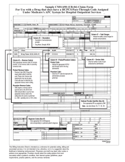


© Copyright 2026