
1941 Patent: Hollow Mortar Shell Design
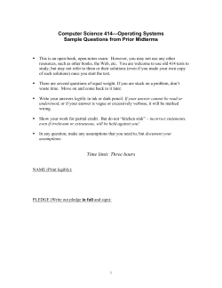
9, v1941-
T. E. MURRAY‘ ETAL
'
‘
.
2,265,652 Y‘
‘HOLLOW SHELL
Filed Nov. 29, 1939
INVENTOR.
THOMAS E. MURRAY
GEORGE H. PHELPS
‘-
‘ff-T,‘ "/
ATTORNEY.
‘2,265,652
Patented Dec. 9, 1941
UNITED STATES PATENT OFFICE‘
2,265,652
HOLLOW snE'LL
Thomas E. Murray, Brooklyn, and George H.
Phelps, Floral Park, N. Y.; said Phelps as
signor to Murray Manufacturing Corporation,
Brooklyn, N. Y., a corporation of New York,
and said Murray assignor to Yarrum, Inc.,
Brooklyn, N. E, a corporation of New York
' Application November 29, 1939, Serial No. 306,632
(01. 29-121)
‘5 Claims.
The invention herein disclosed relates to a
shaped to form one of two interchangeable por
hollow, streamlined shell or projectile of’ the
tions of the shell.
type that is used in a mortar and to a method
of making such a shell.
It has been found expedient to streamline mor
tar shells and to controlthe center of gravity
of the shell throughv the distribution of the metal
of the shell. In this way the shell is prevented
The blank illustrated in Fig. 1 is of the con
?guration obtained by developing in a plane one
of two interchangeable, longitudinal divided
parts which together make up the shell. This
~
.
blank is stamped from plate of a thickness suit
able for the particular sizeof shell being pro
duced. The end portion l of the blank is bent
from tumbling when projected and greater dis
tance and accuracy is attained. To effect this 10 upon itself as illustrated in Fig. 2. In the ?n- .
ished shell this section of the blank is at the
desirable streamlining and distribution of metal,
nose or forward end‘of the shell.
it has been thought to be necessary to forge the
After the ‘end of the, blank is bent back upon
shell and such shells have heretofore been made
itself,>the blank is subjected to drawing opera
as forgin‘gs. After the forging is completed con
siderable machining is required to obtain the 15 tions between suitable dies and caused to assume
the concave form illustrated in Fig. 3. Two- such
requisite external con?guration, wall section and
interchangeable parts 2 and 3 are placed in cor
accuracy. Such forging and machining is slow,
respondingly recessed electrodes with the edges
laborious and expensive and unsuitable for rapid,
quantity production.
of the parts 2 and 3 in registering contact. A
_
By the invention herein disclosed, there is pro 20 current of very great strength is employed for
a brief period of time. While the current is
vided a shell‘ of this type that, and a method
passing, the two parts are pressed together and
for making such shells which, is suitable for
the contiguous edges are caused to embed one
rapid production in very‘ large quantities and
within the other and a coalescence and ingrain
at greatly reduced cost as compared with- the
same shells and methods for producing them 25 ing of the metal is effected. The parts are thus
united integrally such that the shell is of uni
that have been in use prior to this invention. In
‘form strength throughout.
accordance with the invention, there is provided
The rear or tail end of the shell is closed by a
a hollow, streamlined, mortar shell drawn from
perforated cartridge tube 4. This tube is pref
plate. The shell has a heavier wall section in
the region of the nose for the proper distribution 30 erably formed as a cylindrical piece on an auto
matic screw machine and includes the ' perfo
of weight in accordance with the desired loca
rated, hollow cartridge chamber 4a which re
tion of the center of gravity of the shell. This
shell is produced, in accordance with the method ' ceives the cartridge that ignites the propelling
charge, and a solid section 5 that forms the end
of this invention, by first forming the plate to
provide a heavier section in the region of the 35 wall of the cartridge chamber. This end wall is
recessed as at 6 and the wall of this recessed
plate that forms the nose of the shell. The
portion is spread, after the tube is ?nished on‘
plate so formed is drawn to form the shell and
the screw machine, to correspond to, and follow
united electrically at the joint to effect an in
thecurvature of, the end portion of the body
graining of the metal at the joint. A shell of
this type, so constructed, is of uniform strength 40 of the shell. The body of the shell and the
cartridge tube are placed in recessed electrodes
throughout.
'
In the accompanying drawing, there is dis- . and electrically united as at ‘l by an'ingraining
of the metal at the contiguous edges. The ex
closed the blanks and shell that are produced in
ternal burr formed by the extrusion of metal
constructing a shell in accordance with this in
during the weld is removed from the shell.
vention. The drawing includes:
Fig. 1 which is an isometric view of a blank ,
cut from plate;
Fig. 2 which is an isometric view of the same
blank with the end to form the nose of the shell U
bent back upon itself;
Fig. 3 which is an isometric view of the blank
shaped to form one of two interchangeable por
tions of the shell;
'
Fig. 4 which is a side elevation, half in section,
of the shell;
- ’
Fig. 5 which is an isometric view of a modi?ed
form of blank with the end- to form the nose
The shell so formed includes a cylindrical sec
tion between the indicating lines 8. It is im
portant that this section accurately ?t the bore
of the gun to secure the maximum effect of the
propelling charge. To insure that the shell
properly corresponds to the bore of the gun, it is
forced through a truing die, the diameter of
which corresponds to the diameter of the trued
' shell or the bore of the gun.
After the shell is
drawn through ‘the truing die, the grooves 9
I may be machined thereon.
The folding back of the metal in the region of
the nose of the shell provides a heavier wall sec
tion at this portion of the shell. By varying the
bent back upon itself; and
Fig. 6 which is an isometric ‘of, the blank to length or thickness of the turned back portion
2
J 2,265,652
of the shell, the weight of the shell may be dis
illustrated in the drawing and described above
I tributed to so locate the center of gravity of the
the proper internal diameter‘ of the nose of the
shell which is internally threaded to receive the }
within the principle and scope of the invention
as. expressed in the appended claims.
We claim:
1. The method of making a hollow shell having
a heavier wall section adjacent one end thereof
which method includes stamping blanks from
plate, a blank constituting a development in a
fuse cap.
plane surface of a portion of the shell and an '
shell along the longitudinal axis of the shell that
the shell in ?ight will not tumble and will fol-i
low a course such as to secure the greatest range.
The thickened wall section also serves to provide
I
,
In Figs. 5 and 6 the .blank for, and the drawn 10 extension adjacent one end, reversely bending
interchangeable part.of, a modi?ed construction
is illustrated. This construction is especially ad-,
vantageous where a lighter plate, a plate of lesser
thickness than the plate of the blank of Fig‘. 2
the blank to bring the extension into contact
with the blank, and drawing the blank to form
a portion of the shell.
'
2. The method of making a hollow shell having
It is, of course. neces 15 a heavier wall section adjacent one end thereof
sary to maintain the same external diameter of
which method includes stamping blanks from
the shell and the proper internal diameter at the
plate, each blank constituting the development
nose for the fuse cap. .It is also desirable to
in a plane surface of a longitudinally divided
maintain the same longitudinal curvature of the
portion of the shell and an extension at one end,
outer surface of the shell. To this end the con 20 reversely bending the blank to bring the exten
, is used to form a shell.
struction of Figs. 5 and 6 is directed. Inthis
construction, the end section of the blank is fold
sion into contact with the blank, drawing shell
portions from the blanks, arranging the drawn
ed over an insert l0 consisting of a strip of metal
of suitable thickness. The blank with the end to
shell portions with the longitudinal edges in con
tact and in the form of the shell, and effecting a
form the nose folded over the‘ insert is drawn 25 coalescence and ingraining of the metal at the
in suitable dies to obtain the shell part illustrated - contacting edges.
in Fig. 6. - Two such interchangeable, parts are“
3. The method of making a hollow, stream
electrically joined along the contiguous edges as
lined, mortar shell having an ogival front part
heretofore described. The insert Ill provides the
with a heavier wall section in the region of the
necessary thickness at ‘the nose to secure the
forward end thereof and a tapering part at the
requisite internal diameter while maintaining
rear of the front part, which method includes
the same curvature of the shell. In this con
stamping blanks from plate, each blank consti
tuting the development in a plane surface of a
struction, the metal turned back and the insert
at the nose are designed to proportion and dis
longitudinally divided portion of the shell with
tribute the weight and so locate the center of 35 an extension at the forward end, reversely bend
gravity.
ing the blank to bring the extension into contact
In each of the embodiments of the invention
with the blank, drawing the blanks so formed to
disclosed in the drawing and described in detail
form shell‘ portions, arranging the drawn shell ‘
portions with the longitudinal edges in contact
above, the main body of the shell is made of two
longitudinal similar half sections. The nose is 40 and in the form of the shell,'and e?'ecting a
thickened and weighted by reversely bending the
coalescence and ingraining of the metal at the
contacting edges.
\ >
metal. These two sections are welded together
parallel to the longitudinal axis of the shell at
4. The method of making a hollow shell hav
their meeting edges. A single solid closing piece
ing a heavier wall section adjacent one end
is then welded tothe open end opposite the nose
thereof which method includes stamping blanks
in a plane at right angles to the longitudinal
from plate, each blank constituting the develop
weld, in other words, a circumferential weld is
ment in a plane surface of a longitudinally di
made. The purpose of the latter weld is not only
vided portion of the shell- and an extension at
to close the end of the main shell body but also
one end, reversely bending the extension about
to tie together, as it were, the two longitudinal 50 an insert, drawing shell portions from the blanks
halves.
so formed, arranging the drawn shell portions
From the foregoing description of the shell il
with the longitudinal edges in contact and in the
lustrated in the drawing and‘ the method of mak
form of the shell, and effecting a coalescence and
.30
,
ing the shell, it will be seen that by the invention
.ingraining of the metal at the contacting edges.
herein disclosed there is provided a shell which
is readily made, in accordance with the method
of the invention, rapidly, in quantity and less ex
pensively as compared with similar shells and
5. The method of making a hollow, stream
lined mortar shell having an ogival front part
with a heavier wall section in the region of the
forward end thereof and a tapering part at the
rear of the front part, which method includes
methods for making them that have been used ‘
prior to this invention. , The shell is of uniform 60' stamping blanks 'fromplate, each blank consti
strength throughout, accurate in size and the
weight is distributed to properly locate the cen
ter‘of gravity. It will be apparent that the body
tuting the‘ development in a plane surface of a
- longitudinally divided portion of the shell and‘
an extension at the forward end, reversely bend
~ of the shell in the first instance may not be
‘ ing the extension about an insert,f'zdrawing the
drawn or rolled to the precise, final shape of the 65 blanks so formed to form shell portions, arrang
shell. When made from thin metal of a thick
ness of sheet metal or plate, the shell may be
given its streamlined contour by swaging.
'
It will be obvious that various other changes
- may be made by those skilled in the art in the 70
steps of the method and the details of the shell
ing the shell portions with the longitudinal edges
contacting and in the form of a shell, and effect
ing a. coalescence and ingraining of the metal at
the contacting edges;
'
THOMAS E. MURRAY.
GEORGE H. PHELPS.


© Copyright 2026