
Rosemount 585 Annubar Flanged Flo-Tap Assembly ®
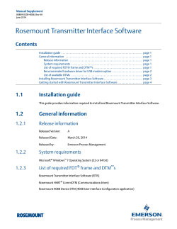
00825-0200-4585_BA.fm Page 1 Tuesday, October 21, 2014 2:32 PM Quick Start Guide 00825-0200-4585, Rev BA October 2014 Rosemount 585 Annubar® Flanged Flo-Tap Assembly 00825-0200-4585_BA.fm Page 2 Tuesday, October 21, 2014 2:32 PM Quick Start Guide October 2014 NOTICE This guide provides basic guidelines for Rosemount 585 Annubar. It does not provide instructions for configuration, diagnostics, maintenance, service, troubleshooting, Explosion-proof, Flame-Proof, or intrinsically safe (I.S.) installations. Refer to the 585 Annubar Reference Manual (document number 00809-0100-4585) for more instruction. This manual is also available electronically on www.rosemount.com. Process leaks may cause harm or result in death. To avoid process leaks, only use gaskets designed to seal with the corresponding flange and o-rings to seal process connections. Flowing medium may cause the 585 Annubar assembly to become hot and could result in burns. Contents 585 Annubar Flanged Flo-Tap Assembly (exploded view). . . . . . . . . . . . . . . . . . . . . . . . . 3 Location and orientation . . . . . . . . . . . . . . . . 4 Weld mounting hardware . . . . . . . . . . . . . . . 8 Install isolation valve . . . . . . . . . . . . . . . . . . . . 9 Mount drilling machine and drill hole . . . 9 2 Remove drilling machine . . . . . . . . . . . . . . . 10 Mount the Annubar . . . . . . . . . . . . . . . . . 10 Insert the Annubar . . . . . . . . . . . . . . . . . . 11 Mount the transmitter. . . . . . . . . . . . . . . 11 Retracting the Annubar. . . . . . . . . . . . . . 16 Product Certifications . . . . . . . . . . . . . . . 17 00825-0200-4585_BA.fm Page 3 Tuesday, October 21, 2014 2:32 PM Quick Start Guide October 2014 585 Annubar Flanged Flo-Tap Assembly (exploded view) H I A B C E D F J K G L A. Compression Plate B. Follower C. Packing D. Packing Gland E. Support Plate F. Isolation Valve G. Gasket H. Remote Mount Process Connection I. Head Plate J. Cage Nipple K. Drive Rods L. Mounting Flange Assembly Note Use an appropriate pipe sealing compound rated for the service temperature on all threaded connections. 3 00825-0200-4585_BA.fm Page 4 Tuesday, October 21, 2014 2:32 PM October 2014 Quick Start Guide Step 1: Location and orientation Correct orientation and straight run requirements must be met for accurate and repeatable flow measurements. Refer to Table 1 for minimum pipe diameter distances from upstream disturbances. Table 1. Straight Run Requirements 1 2 3 4 4 With straightening vanes Downstream dimensions Upstream dimensions Without straightening vanes In plane A Out of plane A A A A’ C C’ 8 10 N/A N/A N/A 4 N/A N/A 8 4 4 4 11 16 N/A N/A N/A 4 N/A N/A 8 4 4 4 23 28 N/A N/A N/A 4 N/A N/A 8 4 4 4 12 12 N/A N/A N/A 4 N/A N/A 8 4 4 4 00825-0200-4585_BA.fm Page 5 Tuesday, October 21, 2014 2:32 PM Quick Start Guide October 2014 Table 1. Straight Run Requirements Without straightening vanes 5 6 With straightening vanes Downstream dimensions Upstream dimensions In plane A Out of plane A A A A’ C C’ 18 18 N/A N/A N/A 4 N/A N/A 8 4 4 4 30 30 N/A N/A N/A 4 N/A N/A 8 4 4 4 Note Consult the factory for instructions regarding use in square or rectangular ducts. “In Plane A” means the bar is in the same plane as the elbow. “Out of Plane A” means the bar is perpendicular to the plane of the elbow. If proper lengths of straight run are not available, position the mounting such that 80% of the run is upstream and 20% is downstream. Use straightening vanes to reduce the required straight run length. Row 6 in Table 1 applies to gate, globe, plug, and other throttling valves that are partially opened, as well as control valves. 5 00825-0200-4585_BA.fm Page 6 Tuesday, October 21, 2014 2:32 PM October 2014 Quick Start Guide Misalignment 585 Annubar installation allows for a maximum misalignment of 3°. Figure 1. Misalignment + -3 + -3 + -3 Horizontal orientation For proper venting and draining, the sensor should be located in the upper half of the pipe for air and gas applications. For liquid applications, the sensor should be located in the bottom half of the pipe. For steam applications, the sensor can be located on either the top or the bottom of the pipe depending on the temperature of the steam. See Table on page 16 for more information. Figure 2. Gas and Steam on Top Recommended Zone 30 6 00825-0200-4585_BA.fm Page 7 Tuesday, October 21, 2014 2:32 PM Quick Start Guide October 2014 Figure 3. Liquid and Steam 30 Recommended Zone Vertical orientation The sensor can be installed in any position around the circumference of the pipe provided the vents are positioned properly for bleeding or venting. Optimal results for liquid or steam are obtained when flow is up. For direct mount steam applications, a 90° spacer will be added to provide water legs to ensure the transmitter stays within temperature limits. Flow Figure 4. Steam and Liquid 360 Flow Figure 5. Gas 360 7 00825-0200-4585_BA.fm Page 8 Tuesday, October 21, 2014 2:32 PM October 2014 Quick Start Guide Step 2: Weld mounting hardware Note Rosemount-supplied mounting has an integral alignment built into the mounting hardware that assists in the correct drilling of the mounting hole. It also assists in the alignment of the sensor to the mounting hole for insertion. 1. At the pre-determined position, place the flanged assembly on the pipe, gap 1 /16-in (1.6 mm), and measure the distance from the outer diameter of the pipe to the face of the flange. Compare this to Table 2 and adjust the gap as necessary. Table 2. Flange Sizes and ODF per Sensor Size Sensor size Flange type 44 44 A Pressure class Flange size/rating/type ODF in. (mm)(1) 1 3.0-in. 150# RF 4.63 (117) 3 3.0-in. 300# RF 5.00 (127) 44 6 3.0-in. 600# RF 5.38 (137) 44 1 4.0-in. 150# RTJ 4.82 (122) 3 4.0-in. 300# RTJ 5.25 (133) 6 4.0-in. 600# RTJ 5.44 (138) 44 R 44 1. Tolerances for the ODF dimension above a 10-in. (254 mm) line size is ±0.060-in. (1,5 mm). Below 10-in. (254 mm) line size is ±0.030-in. (0,8 mm). 2. Place four 1/4-in. (6 mm) tack welds at 90° increments. Check alignment of the mounting both parallel and perpendicular to the axis of flow (see Figure 6). If alignment of the mounting is within tolerances, finish weld per local codes. If outside of specified tolerance, make adjustments prior to making the finish weld. 3. To avoid serious burns, allow the mounting hardware to cool before continuing. Figure 6. Alignment A B A. ODF B. Tack Welds 8 00825-0200-4585_BA.fm Page 9 Tuesday, October 21, 2014 2:32 PM Quick Start Guide October 2014 Step 3: Install isolation valve 1. Position the isolation valve onto the mounting flange. Ensure the valve stem is positioned so that when the Flo-Tap is installed, the insertion rods will straddle the pipe and the valve handle will be centered between the rods (see Figure 7). (Note: Interference will occur if the valve is located inline with the rods.) 2. Fasten the isolation valve to the mounting using gasket, bolts, and nuts. Figure 7. Isolation Valve Orientation A A. Isolation valve Step 4: Mount drilling machine and drill hole Drilling machine is not provided with assembly. 1. Mount the drilling machine to the isolation valve. 2. Open the valve fully. 3. Drill the hole into the pipe wall in accordance with the instructions provided by the drilling machine manufacturer. Drill to 2.5 in. (64 mm). Drill hole has a tolerance of +1/16 / -0 in. (1,6 / -0 mm). 4. Retract the drill fully beyond the valve. Figure 8. Drilling Assembly B A C A. Isolation valve is fully open when inserting drill B. Pressure Drilling Machine C. Isolation valve is fully closed after withdrawing drill 9 00825-0200-4585_BA.fm Page 10 Tuesday, October 21, 2014 2:32 PM Quick Start Guide October 2014 Step 5: Remove drilling machine 1. Verify the drill has been retracted past the valve. 2. Close the isolation valve to isolate the process. 3. Bleed drilling machine pressure and remove. 4. Check isolation valve and mounting for leakage. Step 6: Mount the Annubar 1. Align the flow arrow on the head with the direction of flow. 2. Use the supplied gaskets and flange bolts to fasten the Flo-Tap assembly to the isolation valve. 3. Tighten the nuts in a cross pattern to compress the gasket evenly. 4. Ensure the vent valves are closed before proceeding. 5. Open and close the isolation valve to pressurize the 585 sensor and identify any leak points in the installation. Use extreme caution if the flowing medium is steam or caustic. 6. Check the entire installation for leakage. Tighten as required to stop any connection from leaking. Repeat steps 5 and 6 until there is no leakage. Note Flo-Tap 585 Annubars have the potential to carry a large amount of weight at a great distance from the piping, necessitating external support. The support plate has threaded holes to assist in supporting the 585 Annubar. Figure 9. Install Flo-Tap Assembly A B A. Support Plate B. Isolation Valve 10 00825-0200-4585_BA.fm Page 11 Tuesday, October 21, 2014 2:32 PM Quick Start Guide October 2014 Step 7: Insert the Annubar 1. Open the isolation valve fully. 2. Rotate the crank clockwise. If a power drill with an adapter is used, do not exceed 200 revolutions per minute. 3. Continue rotating the crank until the sensor firmly contacts the opposite side of the pipe. a. The orange stripes are visual indication of when the sensor is approaching the opposite side wall. b. As the orange stripes approach the support plate, remove the power drill and continue cranking manually. Place a finger above the packing gland while cranking. Vibration and movement will occur. When vibration and movements stop, the sensor is in contact with the opposite side wall. Note Do not place finger above packing gland for high temperature applications. c. Turn the handle an additional 1/4 to 1/2 turn to secure the sensor. Figure 10. Insert the Sensor A A. Drive Lock Pin Step 8: Mount the transmitter Transmitter mounting, direct mount head without valves 1. Place O-rings into grooves on the face of head. 2. Orient the equalizer valve(s) so they are easily accessible. Install a manifold with the smooth face mating to the face of the head. Tighten in cross pattern to a torque of 400 in•lb (45 N•m). 3. Place O-rings into grooves on the face of the manifold. 4. Align the high side of the transmitter to the high side of the sensor (“Hi” is stamped on the side of the head) and install. 5. Tighten the nuts in a cross pattern to 400 in•lb (45 N•m). 6. If the DV option is selected, Double Instrument Valves will be provided. Repeat Steps 1-4 to install the redundant transmitter. 11 00825-0200-4585_BA.fm Page 12 Tuesday, October 21, 2014 2:32 PM Quick Start Guide October 2014 Transmitter mounting with remote mount head Temperatures in excess of 250 °F (121 °C) at the sensor module diaphragms will damage the transmitter. Remote mounted transmitters are connected to the sensor by means of impulse piping, which allows service flow temperatures to decrease to a point where the transmitter is no longer vulnerable. Different impulse piping arrangements are used depending on the process fluid and must be rated for continuous operation at the pipeline design pressure and temperature. A minimum of 1/2-in. (12 mm) outer diameter stainless steel tubing with a wall thickness of at least 0.035-in. (1 mm) is recommended. Threaded pipe fittings are not recommended because they create voids where air can become entrapped and create leakage points. The following restrictions and recommendations apply to impulse piping location: Impulse piping that runs horizontally must slope at least one inch per foot (83mm/m). - Slope downward (toward the transmitter) for liquid and steam applications - Slope upward (toward the transmitter) for gas applications. For applications with temperature below 250 °F (121 °C), impulse piping should be as short as possible to minimize temperature changes. Insulation may be required. For applications above 250 °F (121 °C), impulse piping should have a minimum length of one foot (0.3048 m) for every 100 °F (38°C) temperature increase over 250 °F (121 °C). Impulse piping must be non-insulated to reduce fluid temperature. Any threaded connections should be checked after the system reaches the intended temperature because connections may come loose with contraction and expansion caused by temperature change. Outdoor installations for liquid, saturated gas, or steam may require insulation and heat tracing to prevent freezing. When impulse piping is longer than six feet (1.8 m) the high and low impulse lines must be positioned together to maintain equal temperature. They must be supported to prevent sagging and vibration. Impulse lines should be positioned in protected areas or against walls or ceilings. Use appropriate pipe sealing compound rated for the service temperature on all threaded connections. Do not place the impulse piping near high temperature piping or equipment. An instrument manifold is recommended for all installations. Manifolds allow an operator to equalize the pressures prior to zeroing and isolates the process fluid from the transmitter. 12 00825-0200-4585_BA.fm Page 13 Tuesday, October 21, 2014 2:32 PM Quick Start Guide October 2014 Figure 11. Valve Identification for 5-Valve and 3-Valve Manifolds 5-valve manifold 3-valve manifold To PH To PH To PL To PL MV ME ML MH ML MH 2 2 MEL MEH DVL DVH DVL DVH 1 1 Table 3. Description of Impulse Valves and Components Name Description Purpose Components 1 Transmitter Reads Differential Pressure 2 Manifold Isolates and equalizes transmitter Manifold and Impulse Valves PH Primary Sensor(1) PL Primary Sensor(2) DVH Drain/Vent Valve(1) DVL Drain/Vent Valve(2) MH Manifold(1) ML Manifold(2) MEH Manifold Equalizer(1) MEL Manifold Equalizer(2) ME Manifold Equalizer Allows high and low side pressure to equalize MV Manifold Vent Valve Vents process fluid High and low side pressure process connections. Drains (for gas service) or vents (for liquid or steam service) the DP transmitter chambers Isolates high side or low side pressure from the process Allows high and low pressure side access to the vent valve, or for isolating the process fluid 1. High Pressure 2. Low Pressure 13 00825-0200-4585_BA.fm Page 14 Tuesday, October 21, 2014 2:32 PM Quick Start Guide October 2014 Recommended installations Gas service Secure the transmitter above the sensor to prevent condensible liquids from collecting in the impulse piping and the DP cell. Figure 12. Vertical Line Figure 13. Horizontal Line Liquid service Secure the transmitter below the sensor to ensure that air will not be introduced into the impulse piping or the transmitter. Figure 14. Vertical Line 14 00825-0200-4585_BA.fm Page 15 Tuesday, October 21, 2014 2:32 PM October 2014 Quick Start Guide Figure 15. Horizontal Line Steam service (above 450 °F [232 °C]) Mount the transmitter below the process piping. Route the impulse piping down to the transmitter and fill the system with cool water through the two tee fittings. Figure 16. Vertical Line Figure 17. Horizontal Line 15 00825-0200-4585_BA.fm Page 16 Tuesday, October 21, 2014 2:32 PM October 2014 Quick Start Guide Steam on top service Table 4. Steam on Top Temperature Limits Transmitter connection platform Maximum temperature Remote Mount 850 °F (455 °C) Direct Mount 400 °F (205 °C) For remote mount installations the impulse piping should slope up slightly from the instrument connections on the Annubar to the cross fittings allowing condensate to drain back into the pipe. From the cross fittings, the impulse piping should be routed downward to the transmitter and the drain legs. The transmitter should be located below the instrument connections of the Annubar. Depending on the environmental conditions, it may be necessary to insulate the mounting hardware. Figure 18. Horizontal Line Step 9: Retracting the Annubar Gear drive (G) 1. Remove the drive lock pin. 2. Rotate the crank counter-clockwise. If a power drill with an adapter is used, do not exceed 200 rpm. 3. Retract until the rod end nuts are against the gear box mechanism. 16 00825-0200-4585_BA.fm Page 17 Tuesday, October 21, 2014 2:32 PM October 2014 Quick Start Guide Product Certifications European Directive Information A copy of the EC Declaration of Conformity can be found at the end of the Quick Start Guide. The most recent revision of the EC Declaration of Conformity can be found at www.rosemount.com. Ordinary Location Certification from FM Approvals As standard, the transmitter has been examined and tested to determine that the design meets the basic electrical, mechanical, and fire protection requirements by FM Approvals, a nationally recognized test laboratory (NRTL) as accredited by the Federal Occupational Safety and Health Administration (OSHA). Installing Equipment in North America The US National Electrical Code (NEC) and the Canadian Electrical Code (CEC) permit the use of Division marked equipment in Zones and Zone marked equipment in Divisions. The markings must be suitable for the area classification, gas, and temperature class. This information is clearly defined in the respective codes. USA E5 FM Explosionproof (XP) and Dust-Ignitionproof (DIP) Certificate: 3008216 Standards: FM Class 3600 – 2011, FM Class 3615 – 2006, FM Class 3616 – 2011, FM Class 3810 – 2005, ANSI/NEMA 250 – 2003 Markings: XP CL I, DIV 1, GP B, C, D; DIP CL II, DIV 1, GP E, F, G; CL III; T5(-50 °C Ta +85 °C); Factory Sealed; Type 4X I5 FM Intrinsic Safety (IS) and Nonincendive (NI) Certificate: 3031960 Standards: FM Class 3600 – 1998, FM Class 3610 – 2007, FM Class 3611 – 2004, FM Class 3810 – 2005, NEMA 250 – 1991 Markings: IS CL I, DIV 1, GP A, B, C, D; CL II, DIV 1, GP E, F, G; Class III; Class 1, Zone 0 AEx ia IIC T4; NI CL 1, DIV 2, GP A, B, C, D; T4(-50 °C Ta +70 °C); when connected per Rosemount drawing 03151-1206; Type 4x Note Transmitters marked with NI CL 1, DIV 2 can be installed in Division 2 locations using general Division 2 wiring methods or Nonincendive Field Wiring (NIFW). See Drawing 03151-1206. 17 00825-0200-4585_BA.fm Page 18 Tuesday, October 21, 2014 2:32 PM October 2014 Quick Start Guide IE FM FISCO Certificate: 3012350 Standards: FM Class 3600 - 2011, FM Class 3610 - 2010, FM Class 3611 - 2004, FM Class 3616 - 2006, FM Class 3810 - 2005, NEMA 250 - 1991 Markings: IS CL I, DIV 1, GP A, B, C, D; (-50 °C Ta +70 °C); when connected per Rosemount drawing 03151-1006; Type 4x Canada E6 CSA Explosionproof, Dust-Ignitionproof, and Division 2 Certificate: 1143113 Standards: CAN/CSA C22.2 No. 0-10, CSA Std C22.2 No. 25-1966, CSA Std C22.2 No. 30-M1986, CAN/CSA C22.2 No. 94-M91, CSA Std C22.2 No. 142-M1987, CSA Std C22.2 No. 213-M1987, ANSI/ISA 12.27.01-2003, CSA Std C22.2 No. 60529:05 Markings: Explosionproof Class I, Division 1, Groups B, C, D; Dust-Ignitionproof Class II, Division 1, Groups E, F, G; Class III; suitable for Class I, Division 2, Groups A, B, C, D; Type 4x I6 CSA Intrinsically Safe Certificate: 1143113 Standards: CAN/CSA C22.2 No. 0-10, CSA Std C22.2 No. 30-M1986, CAN/CSA C22.2 No. 94-M91, CSA Std C22.2 No. 142-M1987, CSA Std C22.2 No. 157-92, ANSI/ISA 12.27.01-2003, CSA Std C22.2 No. 60529:05 Markings: Intrinsically Safe Class I, Division 1; suitable for Class 1, Zone 0, IIC, T3C; when connected per Rosemount drawing 03151-1207; Type 4x IF CSA FISCO Certificate: 1143113 Standards: CAN/CSA C22.2 No. 0-10, CSA Std C22.2 No. 30-M1986, CAN/CSA C22.2 No. 94-M91, CSA Std C22.2 No. 142-M1987, CSA Std C22.2 No. 157-92, ANSI/ISA 12.27.01-2003, CSA Std C22.2 No. 60529:05 Markings: FISCO Intrinsically Safe Class I, Division 1; suitable for Class I, Zone 0; T3C; when installed per Rosemount drawing 03151-1207; Type 4X Europe E1 18 ATEX Flameproof Certificate: KEMA 00ATEX2143X Standards: EN 60079-0:2012, EN 60079-1: 2007, EN 60079-26:2007 (3051SFx models with RTD are certified to EN 60079-0:2006) Markings: II 1/2 G Ex d IIC T6…T4 Ga/Gb, T6(-60 °C Ta +70 °C), T5/T4(-60 °C Ta +80 °C) Temperature class Process temperature T6 -60 °C to +70 °C T5 -60 °C to +80 °C T4 -60 °C to +120 °C 00825-0200-4585_BA.fm Page 19 Tuesday, October 21, 2014 2:32 PM Quick Start Guide October 2014 Special Conditions for Safe Use (X): 1. The device contains a thin wall diaphragm. Installation, maintenance and use shall take into account the environmental conditions to which the diaphragm will be subjected. The manufacturer's instructions for installation and maintenance shall be followed in detail to assure safety during its expected lifetime. 2. For information on the dimensions of the flameproof joints the manufacturer shall be contacted. I1 ATEX Intrinsic Safety Certificate: Baseefa08ATEX0064X Standards: EN 60079-0: 2012, EN 60079-11: 2012 Markings: II 1 G Ex ia IIC T4 Ga, T4(-60 °C Ta +70 °C) HART® SuperModule™ only RTD (for 3051SFx) Voltage Ui 30 V 7.14 V 30 V Current Ii 300 mA 300 mA 2.31 mA Power Pi 1W 887 mW 17.32 mW 14.8 nF 0.11 uF 0 0 0 0 Capacitance Ci Inductance Li Special Conditions for Safe Use (X): 1. If the equipment is fitted with the optional 90 V transient suppressor, it is incapable of withstanding the 500 V isolation from earth test and this must be taken into account during installation. 2. The enclosure may be made of aluminum alloy and given a protective polyurethane paint finish; however, care should be taken to protect it from impact or abrasion if located in a Zone 0 environment. ND ATEX Dust Certificate: BAS01ATEX1374X Standards: EN 60079-0: 2012, EN 60079-31: 2009 Markings: II 1 D Ex ta IIIC T 105 °C T500 95 °C Da, (-20 °C Ta +85 °C), Vmax = 42.4 V Special Conditions for Safe Use (X): 1. Cable entries must be used which maintain the ingress protection of the enclosure to at least IP66. 2. Unused cable entries must be filled with suitable blanking plugs which maintain the ingress protection of the enclosure to at least IP66. 3. Cable entries and blanking plugs must be suitable for the ambient temperature range of the apparatus and capable of withstanding a 7 J impact test. 4. The SuperModule(s) must be securely screwed in place to maintain the ingress protection of the enclosure(s). 19 00825-0200-4585_BA.fm Page 20 Tuesday, October 21, 2014 2:32 PM October 2014 Quick Start Guide N1 ATEX Type n Certificate: Baseefa08ATEX0065X Standards: EN 60079-0: 2012, EN 60079-15: 2010 Markings: II 3 G Ex nA IIC T4 Gc, (-40 °C Ta +70 °C), Vmax = 45 V Special Condition for Safe Use (X): 1. If fitted with a 90 V transient suppressor, the equipment is not capable of withstanding the 500 V electrical strength test as defined in Clause 6.5.1 of EN 60079-15:2010. This must be taken into account during installation. International E7 IECEx Flameproof and Dust Certificate: IECEx KEM 08.0010X (Flameproof) Standards: IEC 60079-0:2011, IEC 60079-1: 2007, IEC 60079-26:2006 (3051SFx models with RTD are certified to IEC 60079-0:2004) Markings: Ex d IIC T6…T4 Ga/Gb, T6(-60 °C Ta +70 °C), T5/T4(-60 °C Ta +80 °C) Temperature class Process temperature T6 -60 °C to +70 °C T5 -60 °C to +80 °C T4 -60 °C to +120 °C Special Conditions for Safe Use (X): 1. The device contains a thin wall diaphragm. Installation, maintenance and use shall take into account the environmental conditions to which the diaphragm will be subjected. The manufacturer's instructions for installation and maintenance shall be followed in detail to assure safety during its expected lifetime. 2. For information on the dimensions of the flameproof joints the manufacturer shall be contacted. Certificate: IECEx BAS 09.0014X (Dust) Standards: IEC 60079-0:2011, IEC 60079-31:2008 Markings: Ex ta IIIC T 105 °C T500 95 °C Da, (-20 °C Ta +85 °C), Vmax = 42.4V Special Conditions for Safe Use (X): 1. Cable entries must be used which maintain the ingress protection of the enclosure to at least IP66. 2. Unused cable entries must be filled with suitable blanking plugs which maintain the ingress protection of the enclosure to at least IP66. 3. Cable entries and blanking plugs must be suitable for the ambient temperature range of the apparatus and capable of withstanding a 7J impact test. 4. The 3051S- SuperModule must be securely screwed in place to maintain the ingress protection of the enclosure. 20 00825-0200-4585_BA.fm Page 21 Tuesday, October 21, 2014 2:32 PM Quick Start Guide October 2014 I7 IECEx Intrinsic Safety Certificate: IECEx BAS 08.0025X Standards: IEC 60079-0: 2011, IEC 60079-11: 2011 Markings: Ex ia IIC T4 Ga, T4(-60 °C Ta +70 °C) HART SuperModule only RTD (for 3051SFx) Voltage Ui 30 V 7.14 V 30 V Current Ii 300 mA 300 mA 2.31 mA Power Pi 1W 887 mW 17.32 mW 14.8 nF 0.11 uF 0 0 0 0 Capacitance Ci Inductance Li Special Conditions for Safe Use (X): 1. If the equipment is fitted with the optional 90 V transient suppressor, it is incapable of withstanding the 500 V isolation from earth test and this must be taken into account during installation. 2. The enclosure may be made of aluminum alloy and given a protective polyurethane paint finish; however, care should be taken to protect it from impact or abrasion if located in a Zone 0 environment. N7 IECEx Type n Certificate: IECEx BAS 08.0026X Standards: IEC 60079-0: 2011, IEC 60079-15: 2010 Markings: Ex nA IIC T5 Gc, (-40 °C Ta +70 °C) Special Condition for Safe Use (X): 1. If fitted with a 90 V transient suppressor, the equipment is not capable of withstanding the 500 V electrical strength test as defined in Clause 6.5.1 of IEC 60079-15:2010. This must be taken into account during installation. Brazil E2 INMETRO Flameproof Certificate: CEPEL 03.0140X [Mfg USA, Singapore, Germany], CEPEL 07.1413X [Mfg Brazil] Standards: ABNT NBR IEC 60079-0:2008, ABNT NBR IEC 60079-1:2009, ABNT NBR IEC 60529:2009 Markings: Ex d IIC T* Ga/Gb, T6(-40 °C Ta +65 °C), T5(-40 °C Ta +80 °C), IP66* Special Conditions for Safe Use (X): 1. For ambient temperature above 60 °C, cable wiring must have minimum isolation temperature of 90 °C, to be in accordance to equipment operation temperature. 21 00825-0200-4585_BA.fm Page 22 Tuesday, October 21, 2014 2:32 PM October 2014 Quick Start Guide 2. The device contains a thin wall diaphragm. Installation, maintenance and use shall take into account the environmental conditions to which the diaphragm will be subjected. The manufacturer’s instructions for installation and maintenance shall be followed in detail to assure safety during its expected lifetime. I2 INMETRO Intrinsic Safety Certificate: NCC 12.1158X [Mfg USA, Germany] Standards: ABNT NBR IEC 60079-0:2008, ABNT NBR IEC 60079-11:2009, ABNT NBR IEC 60079-26:2008 Markings: Ex ia IIC T4 Ga, T4(-60 °C Ta +70 °C), IP66* Special Conditions for Safe Use (X): 1. If the equipment is fitted with the optional 90 V transient suppressor, it is incapable of withstanding the 500 V isolation from earth test and this must be taken into account during installation. 2. For processes with temperatures above 135 °C, the user must assess whether the SuperModule temperature class is suitable for such applications, because in this situation there is a risk of the SuperModule temperature being above T4. HART SuperModule only RTD (for 3051SFx) Voltage Ui 30 V 7.14 V 30 V Current Ii 300 mA 300 mA 2.31 mA Power Pi 1W 887 mW 17.32 mW 14.8 nF 0.11 uF 0 0 0 0 Capacitance Ci Inductance Li China E3 China Flameproof and Dust Ignition-proof Certificate: 3051SMV: GYJ14.1039X [Mfg USA, China, Singapore] 3051SFx: GYJ11.1711X [Mfg USA, China, Singapore] Standards: 3051SMV: GB3836.1-2010, GB3836.2-2010, GB3836.20-2010 3051SFx: GB3836.1-2010, GB3836.2-2010, GB3836.20-2010, GB12476.1-2000 Markings: 3051SMV: Ex d IIC T6/T5 Ga/Gb 3051SFx: Ex d IIC T6/T5 Ga/Gb; DIP A20 TA 105 °C; IP66 Special Condition for Safe Use (X): 1. Symbol “X” is used to denote specific conditions of use: For information on the dimensions of the flameproof joints the manufacturer shall be contacted. 22 00825-0200-4585_BA.fm Page 23 Tuesday, October 21, 2014 2:32 PM October 2014 I3 Quick Start Guide China Intrinsic Safety Certificate: 3051SMV: GYJ14.1040X [Mfg USA, China, Singapore] 3051SFx: GYJ11.1707X [Mfg USA, China, Singapore] Standards: 3051SMV: GB3836.1-2010, GB3836.4-2010, GB3836.20-2010 3051SFx: GB3836.1/4-2010, GB3836.20-2010, GB12476.1-2000 Markings: 3051SMV: Ex ia IIC T4 Ga 3051SFx: Ex ia IIC T4 Ga, DIP A20 TA 105 °C; IP66 Special Conditions for Safe Use (X): 1. The enclosure may contain light metal, attention should be taken to avoid ignition hazard due to impact or friction. 2. The apparatus is not capable of withstanding the 500 V electrical strength test defined in Clause 6.3.12 of GB3836.4-2010. EAC – Belarus, Kazakhstan, Russia EM Technical Regulation Customs Union (EAC) Flameproof Certificate: Contact an Emerson Process Management representative for additional information IM Technical Regulation Customs Union (EAC) Flameproof Certificate: Contact an Emerson Process Management representative for additional information Japan E4 Japan Flameproof Certificate: TC19070, TC19071, TC19072, TC19073 Markings: Ex d IIC T6 Republic of Korea EP Republic of Korea Flameproof Certificate: 12-KB4BO-0180X [Mfg USA], 11-KB4BO-0068X [Mfg Singapore] Markings: Ex d IIC T5 or T6 IP Republic of Korea Intrinsic Safety Certificate: Contact an Emerson Process Management representative for additional information Combinations K1 Combination of E1, I1, N1, and ND K2 Combination of E2 and I2 K5 Combination of E5 and I5 K6 Combination of E6 and I6 K7 Combination of E7, I7, and N7 KA Combination of E1, I1, E6, and I6 KB Combination of E5, I5, E6, and I6 23 00825-0200-4585_BA.fm Page 24 Tuesday, October 21, 2014 2:32 PM October 2014 Quick Start Guide KC Combination of E1, I1, E5, and I5 KD Combination of E1, I1, E5, I5, E6, and I6 KM Combination of EM and IM KP Combination of EP and IP Additional Certifications SBS American Bureau of Shipping (ABS) Type Approval Certificate: 00-HS145383-6-PDA Intended Use: Measure gauge or absolute pressure of liquid, gas or vapor applications on ABS classed vessels, marine, and offshore installations. ABS Rules: 2013 Steel Vessels Rules 1-1-4/7.7, 1-1-A3, 4-8-3/1.7, 4-8-3/1.11.1, 4-8-3/13.1 SBV Bureau Veritas (BV) Type Approval Certificate: 31910/A0 BV Requirements: Bureau Veritas Rules for the Classification of Steel Ships Application: Class Notations: AUT-UMS, AUT-CCS, AUT-PORT and AUT-IMS SDN Det Norske Veritas (DNV) Type Approval Certificate: A-13243 Intended Use: Det Norske Veritas’ Rules for Classification of Ships, High Speed & Light Craft, and Det Norske Veritas’ Offshore Standards Application: Location classes Type 3051S Temperature D Humidity B Vibration A EMC A Enclosure D / IP66 / IP68 SLL Lloyds Register (LR) Type Approval Certificate: 11/60002(E3) Application: Environmental categories ENV1, ENV2, ENV3, and ENV5 D3 24 Custody Transfer – Measurement Canada Accuracy Approval Certificate: AG-0501, AV-2380C 00825-0200-4585_BA.fm Page 25 Tuesday, October 21, 2014 2:32 PM Quick Start Guide October 2014 Figure 19. Rosemount 585 Declaration of Conformity EC Declaration of Conformity No: DSI 1000 Rev. I We, Emerson Process Management Heath Place - Bognor Regis West Sussex PO22 9SH England declare under our sole responsibility that the products, Primary Element Models 405 / 1195 / 1595 & Annubar® Models 485 / 585 manufactured by, Rosemount / Dieterich Standard, Inc. 5601 North 71st Street Boulder, CO 80301 USA to which this declaration relates, is in conformity with the provisions of the European Community Directives as shown in the attached schedule. Assumption of conformity is based on the application of the harmonized standards and, when applicable or required, a European Community notified body certification, as shown in the attached schedule. As permitted by 97/23/EC, Annex 7, the authorized signatory for the legally binding declaration of conformity for Rosemount/Dieterich Standard, Inc. is Vice President of Quality, Timothy J. Layer. Vice President, Quality (signature) 20-Oct-2011 Timothy J. Layer (date of issue) File ID: DSI CE Marking Page 1 of 3 DSI 1000I-DoC 25 00825-0200-4585_BA.fm Page 26 Tuesday, October 21, 2014 2:32 PM October 2014 Quick Start Guide Schedule EC Declaration of Conformity DSI 1000 Rev. I Summary of Classifications Model/Range 585M - 2500# All Lines 585S - 1500# & 2500# All Lines MSL46 - 2500# All Lines MSR: 1500# & 2500# All Lines 1195, 3051SFP, 3095MFP: 150# 1-1/2͇ PED Category Group 1 Group 2 Fluid Fluid N/A SEP III SEP N/A SEP III SEP I SEP DNF - 150# 1-1/4”, 1-1/2” & 2͇ II II I I I SEP DNF - 300# 1-1/4”, 1-1/2” & 2͇ DNF, DNT, & DNW: 600# 1-1/4”, 1-1/2” & 2” Flanged ̽ 485/3051SFA/3095MFA: 1500# & 2500# All Lines II II II I I SEP FloTap ̽ 485/3051SFA/3095MFA: Sensor Size 2 150# 6͇to 24͇ Line I SEP FloTap ̽ 485/3051SFA/3095MFA: Sensor Size 2 300# 6͇to 24͇ Line II I FloTap ̽ 485/3051SFA/3095MFA: Sensor Size 2 600# 6͇to 16͇ Line II I FloTap ̽ 485/3051SFA/3095MFA: Sensor Size 2 600# 18͇to 24͇ Line III II 1195, 3051SFP, 3095MFP: 300# & 600# 1-1/2͇ 1195, 3051SFP, 3095MFP: 1-1/2” Threaded & Welded FloTap ̽ 485/3051SFA/3095MFA: Sensor Size 3 150# 12͇to 44͇ Line II I FloTap ̽ 485/3051SFA/3095MFA: Sensor Size 3 150# 46͇to 72͇ Line III II FloTap ̽ 485/3051SFA/3095MFA: Sensor Size 3 300# 12” to 72͇ Line III II FloTap ̽ 485/3051SFA/3095MFA: Sensor Size 3 600# 12͇to 48͇ Line III II FloTap ̽ 485/3051SFA/3095MFA: Sensor Size 3 600# 60͇ to 72͇ Line IV* III PED Directive (97/23/EC) Models: 405 / 485 / 585/ 1195 / 1595 QS Certificate of Assessment – CE-0041-H-RMT-001-10-USA IV* Flo Tap - 485/3051SFA/3095MFA: Sensor Size 3 600# 60" to 72" Line (Category IV Flo Tap will require a B1 Certificate for design examination and H1 Certificate for special surveillance) All other models: Sound Engineering Practice File ID: DSI CE Marking 26 Page 2 of 3 DSI 1000I-DoC 00825-0200-4585_BA.fm Page 27 Tuesday, October 21, 2014 2:32 PM Quick Start Guide October 2014 Schedule EC Declaration of Conformity DSI 1000 Rev. I Pressure Equipment Directive (93/27/EC) Notified Body: Bureau Veritas UK Limited [Notified Body Number: 0041] Parklands, Wilmslow Road, Didsbury Manchester M20 2RE United Kingdom File ID: DSI CE Marking Page 3 of 3 DSI 1000I-DoC 27 00825-0200-4585_BA.fm Page 28 Tuesday, October 21, 2014 2:32 PM ?00825-0200-4585? Quick Start Guide 00825-0200-4585, Rev BA October 2014 Emerson Process Management Rosemount Inc. Emerson Process Management Latin America 8200 Market Boulevard Chanhassen, MN USA 55317 T (US) (800) 999-9307 T (Intnl) (952) 906-8888 F (952) 906-8889 1300 Concord Terrace, Suite 400 Sunrise, Florida 33323 USA Tel + 1 954 846 5030 www.rosemount.com Emerson Process Management Asia Pacific Private Limited 1 Pandan Crescent Singapore 128461 T (65) 6777 8211 F (65) 6777 0947/65 6777 0743 Emerson Process Management GmbH & Co. OHG Argelsrieder Feld 3 82234 Wessling Germany T 49 (8153) 9390, F49 (8153) 939172 Beijing Rosemount Far East Instrument Co., Limited No. 6 North Street, Hepingli, Dong Cheng District Beijing 100013, China T (86) (10) 6428 2233 F (86) (10) 6422 8586 © 2014 Rosemount Inc. All rights reserved. All marks property of owner. The Emerson logo is a trade mark and service mark of Emerson Electric Co. Annubar, SuperModule, Rosemount, and the Rosemount logotype are registered trademarks of Rosemount Inc. HART is a registered trademark of the HART Communication Foundation.


© Copyright 2026