
TWR-K40D100M Module Quick Start Guide
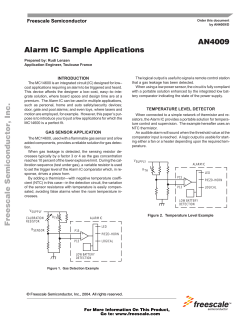
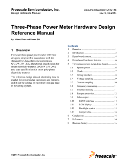
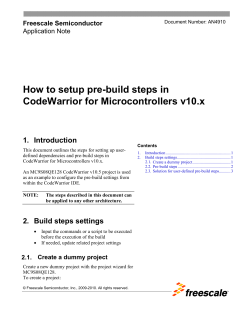
TWR-K40D100M
Quick Start Guide
Low-Power MCU with USB
and Segment LCD
Tower System
Development Board
Platform
Quick Start Guide
Get to Know the TWR-K40D100M Board
Primary
Connector
General-Purpose
Tower Plug-In
(TWRPI) Socket
Infra-Red
SW3 (Reset)
Power/OSJTAG
Mini-B USB
Connector
Secondary
Connector
SW1
SW2
MMA8451Q
Accelerometer
Touch TWRPI
Socket
LED/Touch
Buttons
D7, D8, D9
and D11
MK40DX256VMD10
Kinetis MCU
Figure 1: Front side of TWR-K40D100M board without Tower plug-in (TWRPI)
TWR-K40D100M Freescale Tower System
Development Board Platform
The TWR-K40D100M board is part of the Freescale Tower System, a
modular development board platform that enables rapid prototyping and
tool re-use through reconfigurable hardware. The TWR-K40D100M can be
used with a broad selection of Tower System peripheral boards.
2
freescale.com
TWRPI-SLCD
Board
Figure 2: Front side of TWR-K40D100M board with
TWRPI-SLCD attached
Potentiometer
SD Card
Socket
VBAT (RTC)
Battery
Holder
Figure 3: Back side of TWR-K40D100M board
3
Quick Start Guide
TWR-K40D100M
Features
Step-by-Step
Installation Instructions
• M
K40DX256VMD10 MCU (100 MHz
ARM® Cortex®-M4 core, 512 KB flash,
SLCD, USB FS OTG, 144 MAPBGA)
In this Quick Start Guide, you will learn how
to set up the TWR-K40D100M module and
run the default demonstration.
• Integrated open source JTAG (OSJTAG)
circuit
• MMA8451Q 3-axis accelerometer
• Four user-controlled status LEDs
• F
our capacitive touchpads and two
mechanical pushbuttons
• G
eneral-purpose TWRPI socket (Tower
plug-in module)
• P
otentiometer, SD card socket and
coin-cell battery holder
1
Install the Software
and Tools
Install the P&E Micro
Kinetis Tower toolkit. The
toolkit includes the OSJTAG
and USB-to-serial drivers.
These can be found online at
freescale.com/TWR-K40D100M.
2
Configure the
Hardware
Install the included battery into the VBAT
(RTC) battery holder. Then, plug the
included segment LDC TWRPI-SLCD
into the TWRPI socket. Finally, connect
one end of the USB cable to the PC and
the other end to the power/OSJTAG
4
freescale.com
mini-B connector on the TWR-K40D100M
module. Allow the PC to automatically
configure the USB drivers if needed.
3
Tilt the
Board
Tilt the board side to side to see the
LEDs on D8, D9, D10 and D11 light up
as it is tilted.
4
Navigate the
Segment LDC
The segment LDC will display the seconds
elapsed since boot-up. Press SW2 to
toggle between viewing the seconds,
hours and minutes, potentiometer and
temperature.
5
Explore
Further
Explore all of the features and capabilities
of the preprogrammed demo by reviewing
the lab document located at
freescale.com/TWR-K40D100M.
6
Learn More About
Kinetis K40 MCUs
Find more MQX™ RTOS and bare-metal
labs and software for the Kinetis 40 MCUs
at freescale.com/TWR-K40D100M.
5
Quick Start Guide
TWR-K40D100M Jumper Options
The following is a list of all jumper options. The default installed jumper settings are
shown in shaded boxes.
Jumper
6
Option
J10
V_BRD Voltage
Selection
J13
MCU Power
Connection
J9
VBAT Power
Selection
Setting
Description
1-2
Onboard power supply set to 3.3 V
2-3
Onboard power supply set to 1.8 V
(Some onboard peripherals may not operate)
ON
Connect MCU to onboard power supply (V_BRD)
OFF
Isolate MCU from power (Connect to ammeter to
measure current)
1-2
Connect VBAT to onboard power supply
2-3
Connect VBAT to the higher voltage between
onboard power supply or coin-cell supply
freescale.com
Jumper
J14
J15
J12
J11
Option
OSJTAG Bootloader
Selection
JTAG Board Power
Connection
IR Transmitter
Connection
IR Receiver
Connection
Setting
Description
ON
OSJTAG bootloader mode (OSJTAG firmware
reprogramming)
OFF
Debugger mode
ON
Connect onboard 5 V supply to JTAG port (supports
powering board from JTAG pod supporting 5 V supply ouput)
OFF
Disconnect onboard 5 V supply from JTAG port
ON
Connect PTD7/CMT_IR0 to IR transmitter (D5)
OFF
Disconnect PTD7/CMT_IR0 from IR transmitter (D5)
ON
Connect PTC6/CMP0_IN0 to IR receiver (Q2)
OFF
Disconnect PTC6/CMP0_IN0 from IR receiver (Q2)
ON
Connect USB0_VBUS from elevator to VREGIN
J2
VREGIN Power
Connection
OFF
Disconnect USB0_VBUS from elevator to VREGIN
J3
GPIO to Drive
RSTOUT
1-2
PTE27 to drive RSTOUT
2-3
PTB9 to drive RSTOUT
J1
FlexBus Address
Latch Selection
1-2
FlexBus address latch disabled
2-3
FlexBus address latch enabled
7
Visit freescale.com/TWR-K40D100M,
freescale.com/K40 or freescale.com/Kinetis for
information on the TWR-K40D100M module, including:
• TWR-K40D100M user manual
• TWR-K40D100M schematics
• Tower System fact sheet
Support
Visit freescale.com/support for a list of phone
numbers within your region.
Warranty
Visit freescale.com/warranty for complete
warranty information.
For more information, visit freescale.com/Tower
Join the online Tower community at towergeeks.org
Freescale, the Freescale logo, the Energy Efficient Solutions logo and Kinetis
are trademarks of Freescale Semiconductor, Inc., Reg. U.S. Pat. & Tm. Off.
Tower is a trademark of Freescale Semiconductor, Inc. All other product or
service names are the property of their respective owners. ARM and Cortex
are registered trademarks of ARM Limited (or its subsidiaries) in the EU and/or
elsewhere. All rights reserved. © 2013, 2014 Freescale Semiconductor, Inc.
Doc Number: K40D100MQSG REV 2
Agile Number: 926-78685 REV C


© Copyright 2026