
View PDF - Conference Proceedings
THE AMERICAN SOCIETY OF MECHANICAL ENGINEERS
349 E. 47th St., New York, N.Y. 10017
97-GT-396
The Society shall not be responsible for statements or opinions advanced in papers or dicussion at meetings of the Society or of its Divisions or
Sections, or printed in its publications. Discussion is printed only if the paper is published in an ASME Journal. Authorization to photocopy
material for Internal or personal use under circumstance not falling within the fair use provisions of the Copyright Act is granted by ASME to
libraries and other users registered with the Copyright Clearance Center (C,CC) Transactional Reporting Service provided that the base tee of $0.30
per page is paid directly to the CCC, 27 Congress Street Salem MA 01970. Requests for special permission or bulk reproduction shout, be addressed to the ASMETectinical Pinching Department
Copyright 0 1997 by ASME
All Rights Reserved
Printed in U.S.A
RESULTS OF EXPERIMENTS AND MODELS FOR PREDICTING STABILITY LIMITS
OF TURBULENT SWIRLING FLAMES
S. Hoffmann*, B. Leuze**, H. Eickhoff***
1 III IIIIIIIiillA1)111111111
• Siemens-KWU, 9-45473 Miillielm, KR. Germany
** Engler-Bunte-Institut, Universitat Karlsruhe / D-76I28 Karlsruhe, F.R. Germany
•** DLR, D-51170, Cologne, F.R. Germany
Dedicated to the 65th Birthday of Prof. W. Leuckel
Swirling flames are used in many industrial applications like process furnaces, boilers and gas turbines
due to their excellent mixing, stability, emission and burnout characteristics. The wide-spread use of
swirl burners in the process and energy industries and, in particular, new concepts for the reduction
of NO-emissions raise the need for simple-to-use models for predicting lean stability limits of highly
turbulent flames stabilized by internal recirculation.
Based on recently published experimental data of the first author concerning the reaction structures of
swirling flames operating near the extinction limit, different methods for predicting lean blow-off limits
have been developed and tested. The aim of the investigations was to find stabilization criteria that
allow predictions of blow-off limits of highly turbulent recirculating flames without the requirement
for measurements in those flames.
Several similarity criteria based on volumetric flow rates, burner size and material parameters of the
cold gases, were found to be capable of predicting stability limits of premixed and (in some cases)
nonpremixed flames at varying swirl intensities, burner scales and fuel compositions. A previously
developed numerical field model, combining a k,€-model with a combined "assumed-shape JointPDF"/Eddy-Dissipation reaction model was also tested for its potential for stability prediction.
Presented at the International Gas Turbine & Aeroengine Congress 8z Exhibition
Orlando, Florida — June 2—June 5, 1997
This paper has been accepted for publication in the Transactions of the ASME
Discussion of it will be accepted at ASME Headquarters until September 30,1997
Downloaded From: http://proceedings.asmedigitalcollection.asme.org/ on 12/29/2014 Terms of Use: http://asme.org/terms
INTRODUCTION
Stability, emission and burnout characteristics of swirling flames are used in many industrial
applications like process furnaces, boilers and gas turbines due to their excellent mixing. The swirlinduced formation of a central recirculation zone with heat and chemically active species, plays the
essential role in the stabilization processes in those highly turbulent natural gas flames. The wide-spread
use of swirl burners in combustion systems and new concepts for thermal N0 1-reduction by ultra lean
premixed combustion or/and for fuel N0 1-reduction by air staging (rich/lean combustion zones) raise
the need for simple models to predict lean stability limits of turbulent flames with inner recirculation.
Different methods for the prediction of lean blow-off limits which do not require field measurements
in flames or cold flows will be discussed.
BASIC RELATIONS FOR REACTIONS, STABILITY AND MODELLING
Structures of reaction in swirling flames
The results of our investigations concerning the reaction structures in turbulent swirling flames
published in references 1 and 2 show that intense turbulence in the shear layer between the recirculation
zone and the forward flow results in a well-mixed "distributed reaction zone", where fluid elements
with different reactivities can coexist. Measurements at different flow rates show that aerodynamically
controlled parameters like the mean flow and mixing fields are invariant against Reynolds number
variations, while flame characteristics which are influenced by the chemical reactions such as
temperature and species concentrations show strong variations with flowrate especially at relatively low
Reynolds numbers. Results of experimental and numerical investigations of the stabilization [2,3] reveal
that reactions in swirling flames occur at relatively low turbulent DarnkOhler-numbers, indicating that
the flames are kinetically controlled even at relatively low burner loads. We have shown [11] for the
swirling flames that the reactions are to be located mainly in the Well Stirred Reactor (WSR) Regime.
It is not surprising, therefore, that the processes leading to blow-off of swirling flames resemble those
observed in well-stirred reactors: increased burner loads result in a shortening of residence time inside
the stabilization zone causing a decrease of burnout and temperature due to the reduced heat release
finally resulting in flame blow-off.
Methods for predicting stability limits
Peclet Number Model. The stability limits of premixed and nonpremixe pdersiecircsuilDatiin
a g flames can (b3e)
described by Peclet numbers based upon the blow-off velocity or the laminar flame speed S.
respectively [4,5,6] :
Pe,,, - Pesl°
(1)
Pew = (u, • Lan)/a
(2)
whereby the theoretical value of n is equal 2.
2
Downloaded From: http://proceedings.asmedigitalcollection.asme.org/ on 12/29/2014 Terms of Use: http://asme.org/terms
Due to the experimentally proven Reynolds number invariance of the fully turbulent fiowfield the
characteristic length scale L d is the length of the inner recirculation zone being proportional to the
burner diameter D for geometrically similar burner configurations. Furthermore, the tangential
velocities w are proportional to the swirl number S o and the axial exit velocity u o, so that a
characteristic tangential velocity w= u o•So,o, was considered as a reasonable parameter for a
characteristic velocity.
With this and when u, u o the Peclet numbers can be written as:
(u0 • So. th •
D) / a = Pe„
Pes? = {(S, • D) / a} 2
(uo • So.o,) / D
S? / a
(4)
(5)
The equation (5) allows prediction of stability limits for premixed burners of different scales based on
burner size, flowrate and parameters of the cold gases only and operating with different fuels and swirl
intensities. For nonpremixed combustion, variations of the momentum ratio of gas to air flow cause
variations of the average mixing field due to the different mixing behaviour of the fuel.
The Peclet number model requires values of the laminar burning velocities as an input, whereby values
of SI published in the literature are sometimes not consistent, and for some fuels no data are available.
Moreover, errors in flowrate measurements which lead to some scatter of the stability measurements
also cause errors in S, which was derived according to the blow-off air ratio. In order to avoid those
difficulties, the Peclet number expression can easily be transformed to obtain
(uo •S o.th) I D aS i2 / a
(6)
If only one type of fuel is being considered, the laminar burning velocity and thermal conductivity
depend on the initial air ratio only, so that they can be substituted by an empirical function A [11, 13]:
(110 -So.th) / D = F (Al
(7)
In the last two equations, D/u,, represents a typical residence time in the stabilization zone of the flame,
and Sox, takes into account the effect of air entrainment. This simplified relationship enables prediction
of stability limits of burners of different size at varying swirl intensities. The only input data needed
are the nozzle diameter and blow-off data of a geometrically similar model burner for the determination
of the A-function.
Chemical Reactor Modelling. For swirling flames the intense turbulence in the near field of the burner
leads to the existence of a well-mixed "distributed reaction zone" in the shear layer between the
recirculation zone and the fresh combustible mixture. The processes that cause the flame blow-off
resemble those observed in well-stirred reactors (WSR), which leads to the idea of a relation between
3
Downloaded From: http://proceedings.asmedigitalcollection.asme.org/ on 12/29/2014 Terms of Use: http://asme.org/terms
the blow-off limits of well-stirred reactors and swirling flames.
The critical residence time T wsR of an adiabatic WSR given by the reactor volume divided by the
flowrate at the extinction limit, only depends on fuel type stoichiometry and inlet temperature and is
not influenced by the reactor volume. Hence,
twsR
may also be interpreted as a characteristic chemical
reaction timescale for the relevant oxidation reactions. The WSR calculations were performed using
the PSR code by Glarborg et al. [7] and a detailed reaction mechanism by Miller and Bowman [8]. To
reduce the computational effort, only the reactions of the C-H-0 system were considered.
Following the previous considerations, the residence time in the stabilization zone s name can be
expressed by the typical lengthscale of the burner divided by a characteristic velocity, provided that
geometrical similarity exists. In the present, the burner diameter and the bulk burner exit velocity were
used as characteristic parameters. Comparison of both timescales proves that they are well correlated
to each other, giving the opportunity to predict blow-off velocities of geometrically similar burners
operated with different fuels based on the knowledge of
twsk
and the stability diagram of a model
burner.
Numerical Field Models. Previous investigations [2,3] showed that correct prediction of the general
characteristics and stability limits of swirling flames can only be achieved if the mean flowfield and the
turbulent mixing are adequately predicted. In the numerical model considered, this has been achieved
by accounting for the swirl-induced attenuation or amplification of turbulence by means of a Richardson
number correction applied to the k,e-model, in which the axisynunetric transport equations for the
following variables were solved: velocity, turbulence energy and its dissipation rate, mixture fraction
and its fluctuation, enthalpy, fuel concentration, CO-concentration and temperature fluctuations. The
partial differential equations were solved by a semiimplicit finite volume algorithm following Patankar
and Spalding. A second order differencing procedure (QUICK) on a fine grid allowed the prediction
of the small recirculation zone along the central bluff body, which is important for calculation of the
stabilization limits. We captured the major features by a PDF approach accounting for fluctuating of
temperature (1) and mixture fraction (0 and statistical correlations of related quantities. The reaction
mechanism used was the 2-step methane mechanism following Westbrook and Dryer [9]. In the
numerical model, the actual shape of the PDF was calculated from values of f, T and T'' in a way
that approximates the experimental findings, as explained in Ref [3].
The effective reaction rate is calculated by superposition of the JPDF-reaction rate with the BU-reaction
rate. In Ref. [3] it has shown that the reaction model is suitable for premixed and nonpremixed systems,
provided that the aerodynamic model is able to predict the flow and mixing field correctly. Stability
4
Downloaded From: http://proceedings.asmedigitalcollection.asme.org/ on 12/29/2014 Terms of Use: http://asme.org/terms
limits had to be determined iteratively by the numerical code, which required a considerable
computational effort.
EXPERIMENTS
The experiments on enclosed and non enclosed as well as premixed and nonprernixed flames were
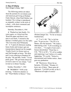
performed for geometrically similar burners. A "Movable-Block" swirl generator allowed for
continuous adjustment of the theoretical swirl number between values of 0 and 2 [10] (Fig. 1). Burners
with nozzle diameters between 60 and 100mm were operated at thermal loads of 250 up to 750kW and
Reynolds numbers > 60,000.
For the diffusion flames fuel gas was supplied through the central bluff-body - the blockage ratio B
being 0,33 - and injected into the concentric, swirling air flow by means of interchangeable 45 ° multihole nozzles or a concentric gas ring. For premixed flames fuel gas was injected radially upstream
of the swirler through eight nozzles in order to provide complete mixing in the burner exit plane and
a watercooled central bluff-body was installed in order to keep the geometry comparable to that of the
diffusion flame experiments with the same blockage ratio [11]. All experiments have been made with
temperature of fuel and air of 20 °C.
The measurements in the near field of the burner included the determination of the velocity and
temperature fields as well as mean values of volumetric concentrations of the relevant stable species
at different flowrates. In addition, the blow-off limits were determined for a variety of swirl numbers,
air to fuel ratios and fuel gas compositions. A counter-type two-colour LDV working in bacicscattering
mode was used for the velocity measurements, magnesia oxide particles with diameters of about 1
micron served as tracer seeds. The turbulent temperature fields were measured using electronically
compensated thermocouples with diameters of 50 and 100 microns [12], the compensation of thermal
inertia resulting in a dynamic range of about licHz. Commercial gas analyzers were used for the
concentration measurements. Sampling was nearly isokinetically by watercooled stainless-steel suction
probes which could be turned into the mainstream direction by means of stepping motors. More
detailed descriptions of the experimental setup are given in [1,2 and 11]. At least some experiments
have been made with enclosed flames with a burner of D = 90 mm and a watercooled combustion chamber of 500 mm diameter and 1000 mm length and a central plate in the chamber exit, so that the
flue gases flow out of the furnace by a ring and no recirculation flow from outside the furnace can
influence the reaction zone (fig. 2).
The results of the detailed velocity, temperature and concentration measurements in the region of the
length of the flame L (L e 3,5 D) have been presented in (fig. 11 and 14).
5
Downloaded From: http://proceedings.asmedigitalcollection.asme.org/ on 12/29/2014 Terms of Use: http://asme.org/terms
RESULTS
The experiments show the basic influences on flame stability limits and assess the stability models for
unconfined burning flames. Figure 3 shows the results of stability measurements on unconfined,
premixed swirling flames at different initial swirl numbers. Combustion is stable for conditions left of
the given data points. At a given swirl number the regime of stable combustion is shifted towards
smaller air ratios with increasing thermal load due to the higher kinetic rates of the mixture. Inereasing
swirl leads to a higher entrainment of air resulting in lower flame temperatures and flame speeds and
in decreasing of the limits of stable combustion in free jet flames. The blow-off curves in Fig. 4 reveal
that the same behaviour can also be observed in the case of nonpremixed swirling flames. In the whole
range of swirl numbers, the diffusion flames display higher stability limits than the comparable
premixed flames. This is due to the fact that fuel concentration is higher in the stabilizing recirculation
zone.
Figure 5 shows stability data evaluated according to the Peclet number relation, based on flame speeds
determined on a Bunsen-flame. The Peclet number dependency correlates the measurements for three
different swirl numbers and four burner sizes rather satisfactorly. In Fig. 6, the stability data of Fig.
5 are presented as a function of the excess air factor A in a semi logarithmic diagram. It can be seen
that the inverse characteristic residence time u o.S.,,h/D is well reproduced by an exponential function
of the form
(•lo • So,th)
= exp
(8)
•I+
with a reduction of the scatter of correlation and with m and B as empirical constants. In order to analyse the influence of kinetic rates or laminar burning velocities on the stability limits of recirculating
flames, additional measurements were carried out using different mixtures of natural gas (95% CH4)
and hydrogen or nitrogen. In the case of hydrogen doped flames, higher content of
widening area of stable operation due to the lower fuel lean ignition limit of
H2
H2
leads to a
compared to CH4 . Fig.
7 presents corresponding curves for a fuel mixture of 66% CH 4 and 34%H2. The stability data are again
represented by a single straight line, only the empirical constants of the exponential function had to be
adapted for this different fuel. The stability data presented in Fig. 8 show that equation (8) is also
applicable to nonprernixed flames. Using Peclet number based models, the stability limits of
geometrically similar turbulent flames of different size operated with different fuels can be predicted
on the basis of stability measurements on a model burner. Furthermore, the simplified model offers the
opportunity to predict the stability limits of diffusion flames. However, the constants of the exponential
function have to be adapted to every combination of burner system and fuel.
6
Downloaded From: http://proceedings.asmedigitalcollection.asme.org/ on 12/29/2014 Terms of Use: http://asme.org/terms
Nomenclature
a
thermal conductivity, m 2/s2
•
blockage ratio = d o2/032 _ do2)
dimensionsless constant [eqn(1)]
•
burner diameter, m
Da
Damkohler number
Ka
Karlowitz number
turbulent kinetic energy, m 2/s2
Ithkr
characteristic lenghtscale, m
•
turbulent length, m
rn
constant
•
exponent [eqn(3)]
Pew
Peclet number based on blow-off velocity
Pe ol
Peclet number based on laminar flame speed
radial distance, m
flame speed m/s
initial swirl number
So
50,o,
theoretical swirl number
temperature °C
•
axial velocity, m/s
•
radial velocity, in/s
tangential velocity m/s
•
axial distance, m
•
turbulent dissipation energy, m 2/s2
excess air factor
•
residence time s
angle of swirl generator
Indices:
air
char
air
characteristic
fuel
blow-off
fl
flame
laminar
WSR well stirred reactor
burner exit
0
flame velocity
turbulent
th
theoretical
Acknowledgements
The investigations were conducted in the frame of projects DFG LE 399/7-1,2 and DFG-SFB167, TP
A9. The authors wish to express their gratitude to the Deutsche Forschungsgemeinschaft (DFG) for the
financial support.
REFERENCES
I.
Hoffmann, S., Lenze, B., "Investigations Concerning Stability Mechanism of Unconfined
Swirling Premixed Flames", Archivum Combustionis, Vol 12, No. 1-4, pp.45-57, 1992
9
Downloaded From: http://proceedings.asmedigitalcollection.asme.org/ on 12/29/2014 Terms of Use: http://asme.org/terms
45*-muttihole nozzle
diffusion flame
concentric nozzle
diffusion flame
E• 117 Ermaxi
■
to ma
40 3fr
TIFier
1.•
trra•
to PMd
central bluff-body
premixed flame
fuel gas
(prerrixed operation)
air
I
cooling water (prented operation)
fuel gas (non premixed operation)
cooing voter
air fol
air + Mel
Fig. 1. Swirl burner for premixed and nonpremixed operation.
fuel gas
726,26
T14,S
fuel gas
T18
suction probe
T17
716
cooling water 1°4'
. !Mal'
719,20
D= 90 nan
116
(I, =58 mm
T21,22,23
112
cooling water
fuel gas
(premixed operation)
air
T3
,
-air
cooling water (premixed operation)
fuel gas (non premixed operation)
Fig. 2. Water coiled furnace with burner, fuel gas exit and temperature-(T) and suction-(S)
probe location
11
Downloaded From: http://proceedings.asmedigitalcollection.asme.org/ on 12/29/2014 Terms of Use: http://asme.org/terms
Nomenclature
a
thermal conductivity, m 2/s2
•
blockage ratio = d o2/032 _ do2)
dimensionsless constant [eqn(1)]
•
burner diameter, m
Da
Damkohler number
Ka
Karlowitz number
turbulent kinetic energy, m 2/s2
Ithkr
characteristic lenghtscale, m
•
turbulent length, m
rn
constant
•
exponent [eqn(3)]
Pew
Peclet number based on blow-off velocity
Pe ol
Peclet number based on laminar flame speed
radial distance, m
flame speed m/s
initial swirl number
So
50,o,
theoretical swirl number
temperature °C
•
axial velocity, m/s
•
radial velocity, in/s
tangential velocity m/s
•
axial distance, m
•
turbulent dissipation energy, m 2/s2
excess air factor
•
residence time s
angle of swirl generator
Indices:
air
char
air
characteristic
fuel
blow-off
fl
flame
laminar
WSR well stirred reactor
burner exit
0
flame velocity
turbulent
th
theoretical
Acknowledgements
The investigations were conducted in the frame of projects DFG LE 399/7-1,2 and DFG-SFB167, TP
A9. The authors wish to express their gratitude to the Deutsche Forschungsgemeinschaft (DFG) for the
financial support.
REFERENCES
I.
Hoffmann, S., Lenze, B., "Investigations Concerning Stability Mechanism of Unconfined
Swirling Premixed Flames", Archivum Combustionis, Vol 12, No. 1-4, pp.45-57, 1992
9
Downloaded From: http://proceedings.asmedigitalcollection.asme.org/ on 12/29/2014 Terms of Use: http://asme.org/terms
.
1000
.
.
0Soth
, = 0.5
• S 0,th = 0.6
O S 0 ,th = 1.0
• Soith = 1.5
CI-14/H2=66/34
0=60mm, 90mm
•
500
•
.
_
so
, o o,
•
0
0 •
0 0
.
•
.c
.
,0
e
o
re
CO
0
stable
-
blow off
• t o0 0
e°
o
• 0
n
100
•
C
.
..
50
1.0
t5
25
20
Fig.7. Correlation of stability data based on the simplified relation Eqs. (7) and (8) for premixed
swirling flames (fuel: 66% CH 4, 34% H2) in dependence on).
600
•
•
I
•
1
eA
S 0 pth = 0.5, 1.0, 1.5
d'
= 3.1 - 7.5Mm
*0
e
400
si
-
a
gf':
vo s
v
stable
= 70mm, 100mm .
D
•Et 0
•
i
•
I
•
s..,
-
a• 'I
0
0 .•
a
a t o
blow off
.
a,•
200
cP
I
turn
—I
i
o
•
•
•
v
0
•
•
i
a
100
0
2
4
6
A
10
12
14
Fig. 8. Correlation of stability data based on the simplified relation (8) for swirling diffusion
flames.
14
Downloaded From: http://proceedings.asmedigitalcollection.asme.org/ on 12/29/2014 Terms of Use: http://asme.org/terms
45*-muttihole nozzle
diffusion flame
concentric nozzle
diffusion flame
E• 117 Ermaxi
■
to ma
40 3fr
TIFier
1.•
trra•
to PMd
central bluff-body
premixed flame
fuel gas
(prerrixed operation)
air
I
cooling water (prented operation)
fuel gas (non premixed operation)
cooing voter
air fol
air + Mel
Fig. 1. Swirl burner for premixed and nonpremixed operation.
fuel gas
726,26
T14,S
fuel gas
T18
suction probe
T17
716
cooling water 1°4'
. !Mal'
719,20
D= 90 nan
116
(I, =58 mm
T21,22,23
112
cooling water
fuel gas
(premixed operation)
air
T3
,
-air
cooling water (premixed operation)
fuel gas (non premixed operation)
Fig. 2. Water coiled furnace with burner, fuel gas exit and temperature-(T) and suction-(S)
probe location
11
Downloaded From: http://proceedings.asmedigitalcollection.asme.org/ on 12/29/2014 Terms of Use: http://asme.org/terms
,
60
.
I
i
0
•
0
0
•
0
•
0
0
.
0
.
0
50
5
0
•
0
• 0
• 0
stable
20
SO,th = it°
SO,th = 15
-
— 500
.
400
•
•
30
•
•
D =100 mm
°
0
0
IkW1
S O,th = S S
o
•
,
I
°•
0
blow off
0
0
0
0
_
_ 300
_
0
200
0
0
_
100
10
1.0
1.2
1.4
1.6
20
Fig. 3. Stability limits of unconfined swirling premixed flames as a function of air equivalence
ratio A and theoretical swirl number S0.tb
20
'
co
El
13
00
>i
12
5 0th = 0.8
.
•
D
SO,th =1-C)
SO,th ' 15
—
D =100 mm
mo
•
on
stable
0
cP
IP.a •
a
8-
blow off
St
o
'
4
alo
•
0
60
Ili
n
I
4.0
-
Os
d
I
g:::::::::::t•CIPM
0.0
0
80
0 00
CD 0 o
0 0_,_n
•
se
n ( lie 0 0 OD
00 00 COM
A
12.0
•
16.0
Fig. 4. Stability limits of swirling diffusion flames as a function of air equivalence ratio A and
theoretical swirl number SO.*
12
Downloaded From: http://proceedings.asmedigitalcollection.asme.org/ on 12/29/2014 Terms of Use: http://asme.org/terms
6
.
.
i
1
1
1
4
'
'
'
'
.
' "
1
'
D = 60, 80, 90, 100mm
•
•
.
. . . ....
0,th
S 0,th=1.5
.
is
p
111
5
-
._
.
-
e is
a 00° •40,,kt
ex. .
0a
0
0
0 , x ...
0 8 0 0 0• %
0
00
°
0°
00
0
0 00
00 0
°
0
..
..
4
4
5
6
log Pe
Fig 5. Correlation of stability data based on Peclet numbers (Eq. (4)), for premixed swirling flames.
.
'
1000
.
500
0
A
.0
.. •
'N. • ,
o• .I' ••
•
'
0)
..
So,t0. 5
o e
• °Qth= 1 .°
• S 0,th=1.5
D = 60, 80, 90, 100mm
/D = exp [m A + 8]
% 1J0 SO,th
10 s
• _ rt,
08
0
• 0
100
stable
S
50
':
—
-
.
n
CI
°0 0
0
°0
blow off
:
-
-
10
1.0
1.5
20
Fig. 6. Correlation of stability data based on the simplified Eq. (8) for swirling premixed flames.
13
Downloaded From: http://proceedings.asmedigitalcollection.asme.org/ on 12/29/2014 Terms of Use: http://asme.org/terms
.
1000
.
.
0Soth
, = 0.5
• S 0,th = 0.6
O S 0 ,th = 1.0
• Soith = 1.5
CI-14/H2=66/34
0=60mm, 90mm
•
500
•
.
_
so
, o o,
•
0
0 •
0 0
.
•
.c
.
,0
e
o
re
CO
0
stable
-
blow off
• t o0 0
e°
o
• 0
n
100
•
C
.
..
50
1.0
t5
25
20
Fig.7. Correlation of stability data based on the simplified relation Eqs. (7) and (8) for premixed
swirling flames (fuel: 66% CH 4, 34% H2) in dependence on).
600
•
•
I
•
1
eA
S 0 pth = 0.5, 1.0, 1.5
d'
= 3.1 - 7.5Mm
*0
e
400
si
-
a
gf':
vo s
v
stable
= 70mm, 100mm .
D
•Et 0
•
i
•
I
•
s..,
-
a• 'I
0
0 .•
a
a t o
blow off
.
a,•
200
cP
I
turn
—I
i
o
•
•
•
v
0
•
•
i
a
100
0
2
4
6
A
10
12
14
Fig. 8. Correlation of stability data based on the simplified relation (8) for swirling diffusion
flames.
14
Downloaded From: http://proceedings.asmedigitalcollection.asme.org/ on 12/29/2014 Terms of Use: http://asme.org/terms
•
•
..
IM
600
•
•b••0 ct
diffusion flames
A Ca
t
i•
fi, a
0
•
0
0
Cr
v 93••
4C
v0 • a
..
4
vy
.•
A
a o
o
o
%
Es
.-
02t,
stable flames
•
8
0
-ol■
•
•
0
.
*
W
lb
no
100
o
premixed flames
50
0
2
4
6
A 8
10
14
Fig. 9 Correlation of stability data based based on the simplified relation for swirling flames in
dependence on A
1.0E-02
.
i
0
•
0
CH4:H2 = 100:0
0H4:H2 = 66:34
CH4:H2 = 77:23
.
.
0
n
'
0
0
0
0
0
•
0
4.0E-03
0
0 0 •
0
0
•
0
0.
0
.
n
o
'
041
2.0E-03
1.0E-04
1.5E-04
2.0E-04
T (WSR)
Fig. 10 WSR-modelling: correlation of characteristic residence time (t
© and TwsR).
15
Downloaded From: http://proceedings.asmedigitalcollection.asme.org/ on 12/29/2014 Terms of Use: http://asme.org/terms
a)
1
I
-00
0
0
0
--
--
--
--
•
°°"
mom
CO
..,
0
I
--,
I
---
• cold furnace S o = 0.8
0 cold furnace S0 = 1.5
• hot furnace So = 0.8
0 hot furnace S. = 1.5
II
1.2
1.3
1.4
16
1.5
1.7
1.8
1.9
excess air A
b)
Illl
,....
•
-....
■
50
-...
/
--...
0•
w
,
0
••/
0. '4.
--:"-0
C Otr-
--...
./.
I
-•
10
.---
-.
•
• cold furnace So = 0.8
0 cold furnace So = 1.5
• hot furnace So = 0.8
0 hot furnace So = 1.5
I
1.6
1.8
2.0
2.2
24
2.6
28
excess air A
Fig. 11. Stability limits of enclosed premixed swirling flames in a hot and cold combustion furnace, (a)
premixed; (b) diffusion flame
16
Downloaded From: http://proceedings.asmedigitalcollection.asme.org/ on 12/29/2014 Terms of Use: http://asme.org/terms
.
1000
.
oS
•
DS
0,ttL
0,th
n•
predictions
•
66
•
•
I. XAA.
Ifs. a
,40.%
.". 0_
4jp Loar voi,
stable
Ae
es,°:
500
5,
D
.
=0.5
0,th
blow off
t
MAI ° oa.
%
CI
0
n no
o
0
% 0
0
o
:0
50
1.0
•.
_r'
-
D= 60, 80, 90, 100mm
10
-
° .°
8
o
—
•
.
t5
A
2.0
Fig. 12 Stability limits calculated from a numerical ((PDF) field model (experimental results: open
symbols; predictions: filled symbols) for different burner diameter D and swirl parameter Sttly
17
Downloaded From: http://proceedings.asmedigitalcollection.asme.org/ on 12/29/2014 Terms of Use: http://asme.org/terms


© Copyright 2026