
Nordberg MP series cone crushers
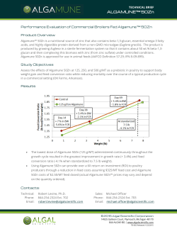
Expect results
Metso’s Mining and Construction Technology
SUBJECT TO ALTERATION WITHOUT PRIOR NOTICE. BROCHURE NO. 2762-06-12-SBL/TAMPERE- ENGLISH ©2012 METSO
Expect results is our promise to our customers and
the essence of our strategy. It is the attitude we share
globally. Our business is to deliver results to our
customers, to help them reach their goals.
Nordberg MP series cone crushers
Wear parts application guide
Wear parts application guide - Nordberg MP series cone crusher
MP cone crusher and basic concepts
The MP Cone crusher is a
compressive crusher in which
feed material is crushed between
a fixed bowl liner and a moveable
mantle. Bigger rock particles are
crushed directly between the
surfaces of the mantle and bowl
liner. This is called single layer
crushing. Smaller rock particles
are crushed between other rock
particles, which is termed multilayer crushing or inter-particle
Comminution. Multi-layer crushing plays a significant role in the
MP cavity. This improves the
reduction through the crusher
and end product shape.
Feed opening
The feed opening defines the maximum
feed size for a crushing cavity. The closed
side feed opening is the smallest distance
between the top of the mantle and bowl
liner as measured when they are at their
closest to one another during their gyrating
cycle.
The open side feed opening is the distance between the top of the mantle and
bowl liner as measured when they are at
their farthest from one another during their
gyrating cycle. In MP cavities, the maximum
feed size is equal to the closed side feed
opening.
Product
Closed side setting (CSS)
The closed side setting has a significant
effect on the product gradation, capacity,
and power draw of an MP cone crusher.
The closed side setting is measured from
the bottom of the mantle to the bottom of
the bowl liner at their closest point during
the gyrating cycle.
Reduction ratio = F80 / P80
2
Nip angle
The nip angle is the angle between the
mantle and bowl liner. Too large a nip angle
reduces the capacity and increases the wear
as feed material will tend to slip back
upward in the cavity rather than crush. This
can be observed as bouncing or boiling of
the feed material.
Reduction ratio
The reduction ratio is the ratio between the
size of feed and the size of the outgoing
product. It is normally measured at the 80%
passing point. A typical reduction ratio in the
MP standard cavity is 4-6 and in the MP short
head cavity it is 3-5.
Feed
How to operate a MP cone crusher
In order to get optimum capacity
and maximum wear life of wear
parts, consider the following
points:
1. Check the feed arrangement:
• The crusher should be choke fed so that
the crushing chamber is full all the time.
This is important, especially in fine crushing. Choke feeding maximizes the amount
of multi-layer crushing, improves the
shape of the crushing cavity as it wears
and improves the crushing efficiency. =>
Choke feed level varies.
• The feed must be distributed evenly 360º
around the crushing chamber. Uneven
feed distribution may cause power and
force cycles through each gyration cycle.
Evenly distributed feed will result in a
more steady power and crushing force.
• Feed should not be segregated (for example finer material on one side of the cavity
and coarser material on the other side of
the cavity).
• Flow of the feed should be stable and
continuous.
2. Check the feed size and gradation:
• Oversize feed material decreases capacity
and can cause abnormal wear of the liners
• Too small a feed size for the cavity increas-
Too big feed material
es the wear at the bottom part of the liners and may cause poor utilization of the
wear parts
• Fines should be screened out before the
material is fed to the crusher as the fines
may cause packing, as well as creating
high forces in the cavity that may lead to
going over the power and/or force limit.
• Feed should be well graded with no gaps
in the size distribution.
Too small feed material
Note: Feed material characteristics
such as gradation, bulk density,
moisture, clay content and
crushability have significant impact
on crusher capacity.
3. Check the power draw. Crusher should
operate with a steady power draw and as
close to full rated power as practical,
depending the circuit design and the
ability to control system.
Example of good feed material level.
3
4. Check the closed side setting. The setting should be close to the required product. The setting is too small if the adjustment ring is moving on the main frame
(ring bounce).
• Larger setting -> Product size increases
• Larger setting -> Capacity increases
• Larger setting -> Power draw decreases
5. Check the crusher operating speed
Check that the operating speed of the crusher matches the application and liner profile
used.
Example of normal wear. Obtained with correct
feed arrangements, feed gradation and parameters for the cavity.
6. Check the cavity in use.
• Based on feed size
• Based on required end product size which
determines the required setting range
• Check the crushing reduction ratio
7. Check the wear profile of the liners: a
distorted wear profile may decrease
capacity, increase the liner wear rate and
increase the crushing force.
Example of abnormal wear. Cupping has occurred.
4
Difficult and Difficult and non Medium and Medium and non
Easy and
abrasive rock
abrasive rock
abrasive rock
abrasive rock
abrasive rock
MP800
XT525/XT520/XT515
XT510
XT710
XT750/XT770
MP1000
XT525/XT520/XT515
XT510
XT710
XT750/XT770
MP1250
XT515
XT525
XT710
XT750/770
● Can be used
●●●
C(●●●)
C
●●●
C(●●●)
C
●●●
C
C
●● Good choice
C(●●●)
●●
C(●●●)
●●
C(●●●)
●●
●●●
C(●●●)
C
C(●●●)
●●
●●●
C(●●●)
C
●●
●●●
C
C
●●●
●
C
C
●●● Recommended ●●●
C(●●●)
C
●●●
C(●●●)
C
●●
●●●
C
C
●●●
●
C
C
Easy and non
abrasive rock
C(●●●)
●
Definitions for different rock types
are presented in Wear and materials
application guide, page 4.
C(●●●)
●
●●●
C
C
C - Contact Metso representative for more information
MP cone crusher cavity selection
Each MP Cone Crusher has several cavity options with different
feed openings and setting ranges. The correct cavity can be
selected based on the feed size,
setting and application.
Standard liners are typically used in secondary applications. Secondary applications
don’t necessarily need to be operated in
closed circuit, but preferably choke fed.
Short head liners are used in tertiary or
quaternary stage applications for fine crushing and may be in closed circuit returning to
the crusher.
Liners are manufactured from XT510,
XT515, XT520, XT525, XT710, XT750 or XT770
material depending on the application and
material characteristics.
Standard
Short head
Crusher size
Cavity
Minimum setting
“A“
Feed
opening “B“
Minimum setting
“A“
Feed
opening “B“
MP800
Extra fine
Fine
Medium
Coarse
Extra coarse
19 mm (0.75 in)
19 mm (0.75 in)
25 mm (0.98 in)
32 mm (1.26 in)
144 mm (5.67 in)
241 mm (9.49 in)
308 mm (12.13 in)
343 mm (13.50 in)
8 mm (0.31 in) 10
mm (0.39 in)
12 mm (0.47 in)
43 mm (1.69 in)
71 mm (2.80 in)
113 mm (4.45 in)
MP1000
Extra fine
Fine
Medium
Coarse
Extra coarse
22 mm (0.87 in)
25 mm (0.98 in)
32 mm (1.26 in)
38 mm (1.50 in)
241 mm (9.49 in)
242 mm (9.53 in)
343 mm (9.57 in)
360 mm (14.17 in)
8 mm (0.31 in)
10 mm (0.39 in)
12 mm (0.47 in)
19 mm (0.75 in)
63 mm (2.48 in)
90 mm (3.54 in)
140 mm (5.51 in)
235 mm (9.25 in)
MP1250
Extra fine
Fine
Medium
Coarse
Extra coarse
22 mm (0.87 in)
25 mm (0.98 in)
32 mm (1.26 in)
38 mm (1.50 in)
249 mm (9.80 in)
250 mm (9.84 in)
351 mm (13.82 in)
368 mm (14.49 in)
8 mm (0.31 in)
10 mm (0.39 in)
12 mm (0.47 in)
71 mm (2.80 in)
98 mm (3.86 in)
148 mm (5.83 in)
1. The minimum setting is that
at which the crusher will operate
without causing ring bounce.
Depending on the crushing characteristics of the rock, this setting
can change.
2. Feed opening “B“ is at a minimum setting “A“.
3. Maximum feed size vary from 80
to 100% of “B“ depending on the
machine size and material.
5
Number of gear
teeth required
for one complete
revolution
Vertical bowl travel
per tooth
Setting variation
per tooth
MP800
306
0.332 mm (0.013 in)
0.22 mm (0.009 in)
16.83 mm (0.663 in)
STD A = 91 + (1.50 x CSS)
SH HD A = 77 + (1.50 x CSS)
MP1000
120
0.626 mm (0.025 in)
0.41 mm (0.016 in)
12.42 mm (0.489 in)
STD A = 76 + (1.50 x CSS)
SH HD A = 105 + (1.50 x CSS)
MP1250
120
0.626 mm (0.025 in)
0.41 mm (0.016 in)
12.42 mm (0.489 in)
STD A = 123 + (1.50 x CSS)
SH HD A = 141 + (1.50 x CSS)
Crusher size
Setting for 1/4 revolution “A“ Approximate dimension
of the driver ring
when the liners are worn out
When to change liners
In order to avoid damage to the
liner seating surfaces of the
crusher head or bowl, wear parts
must be replaced before they are
worn through. In normal conditions, approximately 50% of the
liner weight is consumed when
liners are worn out. It is important to keep a record of liner
wear in order to assess the
degree of liner wear without the
need to stop the crusher operation.
See the following instructions
1. On the initial set of new liners, place a
mark on the adjustment cap driver ring
where the pinion tooth makes contact with
a driver ring tooth when the target crusher
setting has been achieved.
2. Keep an accurate record of the number of
teeth used to compensate for liner wear on
this set of liners.
3. After the initial set of liners have worn out,
but before moving the bowl, record the total
number of teeth the driver ring has moved
and also paint a horizontal liner on the side
of the dust shell just below the bottom of
6
the adjustment cap. This will be the baseline
for determining how close the next liner sets
are to being worn out.
rather than spread along the full cavity and
the cavity may have to be replaced before
they are fully worn. This results in poor utilization and a higher operating wear costs.
4. When a new liner set has been installed,
keep a record of the number of teeth the
driver ring has moved and compare this
number to the total number from the initial
set of liners. This will give an estimation of
the liner wear. The horizontal mark painted
on the dust shell will also indicated when
the liners are approaching the wear limit.
The approximate minimum heights of the
adjustment cap (A-dimension) with worn liners are listed in the attached tables.
When changing liners and determining liner
wear, follow the instructions in the related
Nordberg MP cone crusher instruction manual.
Production considerations may sometimes
favor changing of wear parts before they are
fully utilized. Hourly capacity or product
quality may decrease toward the end of the
liner wear life and it may be more economical to change before the end of the liner
wear life.
Typically, distorted or heavily worn wear
profiles can cause a reduction in capacity.
Other symptoms of poorly worn liners are
high power draw and ring bounce. Also, the
wear life can be reduced because the wear is
sometimes concentrated in a small zone
Caution: A is given for a good wear.
Meaning similar mantle and concave
wear, without distorted wear profile
= correct application according to
cavity selected.
Legal notice
Metso reserves the right to make changes in
specifications and other information
contained in this publication without prior
notice and the reader should in all cases
consult Metso to determine whether any
such changes have been made. This manual
may not be reproduced and is intended for
the exclusive use of Metso customer.
The terms and conditions governing the sale
of Metso hardware products and the
licensing and use of Metso software
products consists solely of those set forth in
the written contract between Metso and its
customer. No statement contained in this
publication, including statements regarding
capacity, suitability for use, or performance
of products, shall be considered a warranty
by Metso for any purpose or give rise to any
liability of Metso.
In no event will Metso be liable for any
incidental, indirect, special, or consequential
damages (including lost profits), arising out
of or relating to this publication or the
information contained in it, even if Metso
has been advised, knew, or should have
known of the possibility of such damages.
Metso, 2012. All rights reserved.
7


© Copyright 2026