
t Example
4/8/2012
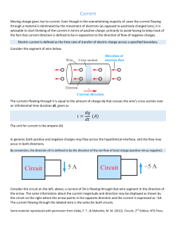
• Whenever electric charges of like signs move under the influence of an applied of electric field, an electric current is said to exist A • The current is the rate at which the charge moves in the wire. l
Definition of the current: • The average current that passes any point in a conductor during ΔQ
a time Δt is defined as (17.1) I =
Δt
• where ΔQ is the amount of charge crosses the shaded area in a time Δt . dQ
(17.2) The instantaneous current is I =
dt
The S.I . Current unit is the ampere ( A ) .often it is convenient to use the milliampere (mA) 1mA = 10‐3 A Also 1μ A =10 ‐6 A 1n A =10 ‐9 A 1 pA = 10‐12 A One ampere of current is one coulomb per second: 1A =
A 3.8x10²¹ electrons pass through a point in a wire in 4 minutes. What was
the average current?
1C
.
1s
• In a metallic conductor, the current is due to the motion of electrons,
so the direction of the current will the opposite to the direction of flow
of the electrons.
• Charges flow only if there is a potential difference. Something
that provides a potential difference is known as a voltage
source
Example Iav =
ΔQ Ne
=
Δt
Δt
( 3.8 ×10 )(1.6 ×10 )
21
Iav =
−19
( 4 × 60 )
Iav = 2.53A
1
4/8/2012
Example 17.1 An electrochemical cell consists of two silver electrodes placed
in an aqueous solution of silver nitrate .A constant 0.5 A current
is passed through the cell for one hour ,
A ) Find the total charge transported through the cell in
coulombs and in multiples of the electronic charge .
B ) Each electrons reaching the cell discharges one positively
charged silver ion, which is then deposited on the negative
electrode (cathode ) . What is the total mass of the deposited
silver?(the atomic mass of silver is 107.9 u., 1u = 1.66 10-27 kg)
Solved in the course’s text book The current is the product of the electronic charge ( e ) , the
density of conduction electrons ( n ) , the area ( A ) and the drift
velocity ( vd )
The current also depends on the resistance that the conductor
offers to the flow of charge which is called electric resistance
The relation between the current in a wire with the density of conduction electrons and their drift velocity Let n be the number of mobile charge carriers per unit volume (the density of conduction electrons ) its unit is electron/m3, The total number of charge carriers in the volume (V) of the conductor is N = n .Volume = n.A .l where the Volume = A . l Charge of one electron (the
electronic charge ) = e = 1.6 x 10 ‐19 C ΔQ = [number of ch arg es ( N )]× [electronic charge (e )]
Δ Q = ne A A
I
av
=
A
ΔQ
= ne
A
Δt
Δt
The drift speed, vd, is the speed at which the carriers move
A
(17.3) I av = nev d A
v d = Δt
Example 17‐2 Number 12 copper wire is often used to wire house- hold electrical outlets .
Its radius is 1mm =10-3 m,if it carries a current of 10 A ,what is the drift
velocity of the electrons ? ( metallic copper has one conduction electron
per atom , the atomic mass of copper is 64 u , and the density of copper is
8900 Kg m-3 ) ,
1u =1.66 x 10⁻²⁷ Kg
The number of atoms per unit volume( n) x the mass of one atom (M )= the
mass of a unit volume of copper =The density (d )
d = n×M
n =
8900 Kg m − 3
d
=
= 8 . 38 × 10 28 electron / m − 3
(64 u)(1.66 × 10 - 27 Kg u -1
M
(
)
A = π r 2 = 3 .14 × 10 − 3 = 3 .14 × 10 − 6 m 2
νd =
2
I
10 A
=
= 2 . 37 × 10 − 4 m / s
nqA (8 .38 × 10 28 m − 3 )(1 . 60 × 10 −19 C )( 3 . 14 × 10 − 6 m 2 )
2
4/8/2012
Conceptual questions Conceptual questions • Suppose a current-carrying wire has a cross-sectional area that
gradually becomes smaller along the wire, so that the wire has the
shape of a very long cone. How does the drift speed vary along the
wire?
(a) It slows down as the cross section becomes smaller.
(b) It speeds up as the cross section becomes smaller.
(c) It doesn’t change.
(d) More information is needed.
These four wires are made of the same metal. Rank in order, from
largest to smallest, the electron currents Ia to Id .
A. Id > Ia > Ib > Ic B. Ib = Id > Ia = Ic C. Ic > Ib > Ia > Id D. Ic > Ia = Ib > Id E. Ib = Ic > Ia = Id (b). Under steady-state conditions, the current is the same in all
parts of the wire. Thus, the drift velocity, given by vd = I / n e A , is
inversely proportional to the cross-sectional area
T.Norah Ali Almoneef 9 Ohmic and Nonohmic Materials 17-2 Resistance
The electrical resistance R of a conductor is the potential difference V
between its ends divided by the current I
R=
V
I
(17.4) Ohm’s law 1Ω=
The S . I. unit of resistance is the ohm:
Resistances of kilohms and megohms are common: 1 kΩ = 10 Ω, 1 MΩ=10 Ω.
3
6
1V
.
1A
For many materials , the potential difference
and the current are directly proportional ,so
the resistance is a constant independent of
the current
The ratio R = V / I is constant
Materials with a constant resistance
are said to obey Ohm’s law and are
called ohmic conductors
Example 17.3 Find the resistance of the wire in
figure 17.2
Solved in the course’s text book Figure 17.2. (a) copper wire has a variable potential difference V between its end (b) the current varies linearly with the potential difference in the wire ,so it is an ohmic conductor 3
4/8/2012
Materials that do not follow Ohm’s Law are
called “nonohmic” materials, and have curved I
vs. V graphs.
Every ohmic material has a
characteristic resistivity that depends
on the properties of the material and
on temperature, i.e., resistivity is a
property of substances
Figure 17.3 the current versus potential difference graph for a rectifying transistor which produces a large current in one direction, produces only a small current in the opposite direction. This is an example of a conductor that does not satisfy ohm’s law • R depends on the material type and shape
• resistance of a metal wire is directly proportional to its length, and
inversely proportional to its cross-sectional area, A:
– R – resistance (Ω)
L
– ρ – resistivity (Ω m)
R = ρ
( 17. 5 ) A
– L – length (m)
RA
– A – cross sectional area (m2)
( Ω .m )
ρ =
A
A
1
1
−1
σ =
= c o n d u c tiv ity
σ =
=
( 17. 6 ) ( Ω .m )
ρ
ρ
R A
¾ Thick wires have less resistance than thin wires. Longer wires
have more resistance than short wires.
¾ If the conductivity of the material the wire is made of is high.
then there will be less resistance.
Resistivities in Ω m at 200C
Table 17.1
substance Resistivity { ρ } [Ω m] conductors
semiconductors
Insulators
Silver 1.47x10‐8 Cooper 1.72x10‐8 Aluminum 2.63x10‐8 Germanium 0.60 Silicon 2300 Glass 1010 – 1014 Sulfur 1015 Example 17 . 4 Find the room temperature resistance of a copper wire 100 m long with
a radius of 1 mm = 10-3 m
( from table 17 .1 ρ copper at room
temperature( 200C) is 1.72 x 10 -8 Ω . m )
Solved in the course’s text book Ionic conductors
Body fluids approx. 0.15 • Good conductors
have low resistivities
• Good insulators have high resistivities
4
4/8/2012
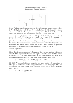
Example: Example: A small flashlight bulb draws 300 mA from its 1.5‐V battery. (a) What is the resistance of the bulb? (b) If the voltage dropped to 1.2 V, how would the current change? R =
I =
1 .5
V
=
300 × 10
I
−3
= 5Ω
V
1 .2
=
= 0 . 24 A = 240 mA
R
5
A 0.900-V potential difference is maintained across a 1.50-m length
of tungsten wire that has a cross-sectional area of 0.600 mm2.
What is the current in the wire?
2
A = ( 0.600 m m
I=
⎛ 1.00 m ⎞
−7
⎟ = 6.00 × 10 m
⎝ 1 000 m m ⎠
)2 ⎜
(
( 0.900 V ) 6.00 × 10 − 7 m 2
ΔV A
=
ρA
5.60 × 10 − 8 Ω ⋅ m ( 1.50 m
(
)
2
)
)
I = 6.43 A
Conceptual questions ¾ A cylindrical wire has a radius r and length L . If both r and L are
doubled, the resistance of the wire
(a) increases
Answer: (b). The doubling of the radius (b) decreases
causes the area A to be four times as (c) remains the same
large, so the resistance decreases. ¾
A cylindrical copper rod has resistance R. It is reformed to twice
its original length with no change of volume. Its new resistance is:
1. R
2. 2R
3. 4R
4. 8R
5. R/2
Conceptual question ¾ If a piece of wire has a certain resistance, which wire made
of the same material will have a lower resistance?
A ) a thicker wire أﺳﻤﻚ
B ) a longer wire أﻃﻮل
Ans: A
C ) a thinner wire أرق
Conceptual questions ¾ If the length of a wire increased, the current flow
decreases because of the longer path
¾ If the area of a wire increased, the current flow
increases because of the wider path
R = ρ L/A
¾ If we change to a material with better conductivity, the current flow
increases because charge carriers move better
5
4/8/2012
Quiz 1 Quiz 3 If a current of 80.0 mA exists in a metal wire, how many electrons flow
past a given cross section of the wire in 10.0 min?
N = 3.00x10²⁰ electrons
Quiz 2 A small flashlight bulb draws 300 mA from its 1.5-V battery.
Birds resting on high-voltage power lines are a common
sight. The copper wire on which a bird stands is 2.2 cm in
diameter and carries a current of 50 A. If the bird’s feet are
4.0 cm apart, calculate the potential difference across its
body.
ΔV = 89 μV
Quiz 4 (a) What is the resistance of the bulb?
(b) (b) If the battery becomes weak and the voltage drops to 1.2 V, how
would the current change?
a ) R = 5.0 Ω.
b ) the current will drop to 240 mA.
Calculate the diameter of a 2.5 cm length of tungsten
filament in a small light bulb if its resistance is 0.047 Ω (The
electrical resistivity of tungsten is 5.6 x10⁻⁸ Ω .m )
d = 0.18 x10⁻² m
summary Average current
Instantaneous current
Number of the electrons
ΔQ
Δt
dQ
I =
dt
ΔQ
N =
e
I =
Home work: 1, 10, 11, 13 and 18 Magnitude of the current
I av = nev d A
Resistance of a conductor
V
R =
I
Resistance is determined by the geometry
and by the resistivity of the material
R = ρ
L
A
6
4/8/2012
17.5 series and parallel resistors ;Kirchhoff’s rules
Statement of Kirchhoff’s Rules • Junction Rule (∑ I = 0) – The sum of the currents entering any point must equal the sum of the currents leaving that junction • A statement of Conservation of Charge ∑
I in =
∑
I out
• I1 = I2 + I3
• Loop Rule (∑ V = 0) – The sum of the potential changes around any
closed circuit loop must be zero
– You must go around the loop in one direction
– The sum of the measured will equal zero
(a) The voltage across a battery is taken to be
positive (a voltage rise) if traversed from – to +
and and negative if traversed in the opposite
direction.
(b) The voltage across a resistor is taken to be
negative (a drop) if the loop is traversed in the
direction of the assigned current and positive if
traversed in the opposite direction.
Vba = ‐ IR Vba = IR Example There are “two” ways to connect circuit elements.
Calculate the current I flowing into the node
∑
I in =
∑
I out
(3+ I ) A = 2 A
I = 2 -3 = -1 A
The current flowing into the node is – 1 A which is the same as +1 A
flowing out of the node
Example
Calculate the current I defined in the diagram
I +2 A = - 4 A
I = (- 4 – 2 ) A = - 6 A
I is in the opposite direction
I+I=6A
I= (6 –6 )A=A
I
1) Series combination:
R1
Kirchhoff’s rules :The sum of the potential changes
around any closed circuit must be zero
ε = I Rs
⇒
I =
I
R3
ε
( a ) Rs
I
Rs
ε −V1−V 2 −V 3 = 0
ε − I R1 − I R 2 − I R 3 = 0
ε
I =
R1 + R 2 + R 3
R s = R1 + R 2 + R 3
R2
V2
V3
V1
Apply the Loop Rule I
+-
The current is the same in resistors because any charge that flows through
one resistor flows through the other but the potential differences across
them are not the same
ε
I
( 17 . 12 )
V
+ -
ε
( b ) Figure 17‐ 10 (a) three resistors in series ( b) the equivalent resistance Rs leads to the same current I, 7
4/8/2012
I1
I2
the current entering point A must equal that leaving
OR
I=
I1 =
Rp
ε
R1
I2 =
ε
R2
I3 =
ε
I I3
ε
Rp
I
A
I
B
(17. 13 )
+ -
I
ε
( b ) I
I1 =
Rp
ε
R1
ε
R2
I3 =
B
R3
1
1
1
1
=
+
+
R p R1 R2 R3
I I3
ε
+-
R3
ε
I
ε
Figure 17 .11 ( a ) three resistors in parallel . ( b ) the equivalent single resistance Rp produces the same current I Rp
I
A
I
(a ) B
V
(17. 13 )
+ -
I
ε
( b ) I
Figure 17 .11 ( a ) three resistors in parallel . ( b ) the equivalent single resistance Rp produces the same current I Example Example 17.10 (a ) find the equivalent resistance of the resistors in figure 17.10 a ( b ) the current I in each resistor Solved in the text book I2 =
ε
⎛ 1
1
1 ⎞
⎟⎟
+
+
= ε ⎜⎜ +
+
I=
R1 R2 R3
⎝ R1 R2 R3 ⎠
⎛ 1
1
1 ⎞
ε
⎟⎟
= ε ⎜⎜ +
+
Rp
⎝ R1 R2 R3 ⎠
ε
(a ) V
ε
R2
A
I = I1 + I 2 + I 3
I=
+-
I
ε
1
1
1
1
=
+
+
R p R1 R2 R3
the current entering point A must equal that leaving
OR
B
R3
⎛ 1
1
1 ⎞
⎟⎟
+
+
= ε ⎜⎜ +
+
I=
R1 R2 R3
⎝ R1 R2 R3 ⎠
⎛ 1
1
1 ⎞
ε
⎟⎟
= ε ⎜⎜ +
+
Rp
⎝ R1 R2 R3 ⎠
ε
I2
R2
R3
ε
R1
2) Parallel combination A
I = I1 + I 2 + I 3
ε
I1
R1
2) Parallel combination A) Find the current in the circuit shown in the figure. B ) Find the potential difference across each circuit element.
solution (a ) In the figure ,we had a 3kΩ, 10 kΩ, and 5 kΩ resistor in series.
R s = R1 + R 2 + R 3
R s = 3 k Ω + 10 k Ω + 5 k Ω = 18k Ω
I =
(b ) V
9
=
= 0 .5 A
Rs
18
V 1 = IR 1 = 0 . 5 × 3 = 1 . 5 V
V 2 = IR 2 = 0 . 5 × 10 = 5 V
V 3 = IR 3 = 0 . 5 × 5 = 2 . 5 V
( c ) 8
4/8/2012
Example Example From the figure find ( a ) I ( total current ) , Rp ( total resistance )
(b) I1 , I2 , I3
1
R
I1 =
I
1
1
1
11
+
+
=
3
6
9
18
=
p
2
=
I3 =
V
⇒
R
p
=
18
= 1 . 64 Ω
11
A.
B.
C.
D.
E.
.
18
= 6 A
3
18
=
= 3 A
6
=
R1
V
R2
V
R3
=
Four resistors are connected as shown in figure. Find the equivalent
resistance between points a and c.
18
= 2 A
9
4 R.
3 R.
2.5 R.
0.4 R.
Cannot determine from information given
∑ I in = ∑ I out
I = I1 + I 2 + I3
I = 6 A + 3 A + 2 A = 11 A
Conceptual questions • From the circuit with source voltage V and Total current I, which
resistor will have the greatest voltage across it?
The resistor with the largest resistance (30 Ω)
• Which resistor has the greatest current flow through it?
Same for all because series circuit
• If we re-ordered the resistors, what if any of this would change?
Nothing would change
20Ω 10Ω V I 30Ω • If we added a resistor in series with these, what would happen
to the total resistance, total current, voltage across each resistor,
and current through each resistor?
Total resistance would increase
Total current would decrease
Voltage across each resistor would decrease
(All voltage drops must still sum to total in
series circuit; Kirchhoff’s law of voltages)
Current through each resistor would be lower
(total current decreased, but same through
each one)
9
4/8/2012
Conceptual questions • from the circuit with source voltage V and Total current I, which resistor
will have the greatest voltage across it?
All the same in parallel branches
• Which resistor has the greatest current flow through it?
The “path of least resistance” (10Ω)
• What else can you say about the current through each branch?
They will sum to the total I (currents sum in parallel circuits; Kirchhoff’s law
of current)
17.12 Kirchhoff’s rules in complex circuits Kirchhoff’s rules permit us to analyze any dc circuit .including circuits too complex
Using the two rules
(1) the sum of all the potential drops around any closed path in a
circuit is equal to zero.
(2) The current entering any point = The current leaving.
Example 17.15 Find the current in the circuit shown in the figure Solved in the text book • If we added a resistor in parallel with these, what would happen to
the total resistance, total current, voltage across each resistor, and
current through each resistor?
Total resistance would decrease
Total current would increase
Voltage across each resistor would still be V
Current through each resistor would be higher and would sum to new
total
Example b Calculate ΔVab
+
9V
ΔVab= 27V +
9V
ΔVab if one battery is reversed?
Δvab= 9v +
9V
a 10
4/8/2012
Example Example Find the current I, r and ε.
Calculate the current in the circuit. 3
∑V
i
Junction rule at a: 2 A+1 A‐I=0 I = 3 A Loop (1): 12 V‐Ir ‐(3 Ω)(2 A)=0 r =12 V/(3 A)‐6 V/(3 A) =2 Ω Loop (2): =0
i =1
12 − I − 5I − 5I − 4 − I + 2 − I − 3I = 0
10 − 16 I = 0
I=
‐ε +(1 Ω)(1 A)‐( 3 Ω)(2 A)=0 10
= 0.625 A
16
ε =‐5 V (polarity is opposite!) Check with loop (3): 12 V‐(2 Ω)(3 A)‐(1 Ω)(1 A)+ε =0 ε =‐5 V Conceptual questions Conceptual questions What is the current in branch P?
5 A Which of the equations is valid for the circuit below?
1 Ω A) 2 A 8 A B) 3 A P C) 5 A I2
A) 2 – I1 – 2I2 = 0 2 A D) 6 A B) 2 – 2I1 – 2I2 – 4I3 = 0 E) 10 A C) 2 – I1 – 4 – 2I2 = 0 The current entering the junction in red
is 8 A, so the current leaving must also
be 8 A. One exiting branch has 2 A, so
the other branch (at P) must have 6 A.
S 5 A P 8 A Junctio
n 2 A 6 A D) I3 – 4 – 2I2 + 6 = 0 2 Ω 6 V 2 V 4 V I1
1 Ω I3
3 Ω E) 2 – I1 – 3I3 – 6 = 0 11
4/8/2012
Quiz summary
Calculate the currents I1, I2, and I3 in the three branches of the circuit in
the figure.
Kirchhoff’s Rules 1‐ Junction Rule 2‐ I in =
∑V
i
∑
I out
=0
i
I1 = - 0.87 A.
I2 = 2.6 A.
I3 = 1.7 A.
Home work
Loop Rule ∑
Series combination:
R s = R1 + R 2 + R 3 + − − − −
Parallel combination:
1
1
1
1
=
+
+
+−−−−
R p R1 R 2 R3
45,46,71 12


© Copyright 2026