
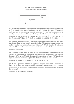
D2HW-A201D - Omron Electronic Components
Sealed Subminiature Snap Action Switch
D2HW
Smallest Sealed Snap-Action Switch in
the Industry With a Long Stroke For
Reliable ON/OFF Action
• Conforms to IP67
• Case dimensions 22% smaller than conventional models
• Extra-long stroke even without levers
(OT: 1.4 mm)
• All models are lead-free, including lead wire models
• RoHS Compliant
Ordering Information
Add “S” to the end of the model number for the UL/CSA-approved version. Consult your OMRON sales representative for details.
■ PCB-Mounted Models
Actuator
Pin plunger
Terminals
For PCB
Hinge lever
Long hinge
lever
Simulated roller
lever
Contact form
Straight
SPDT
Model
With posts on right
With posts on left
Without posts
---
---
D2HW-A201D
Angled
D2HW-BR201DR
D2HW-BL201DL
---
Straight
---
---
D2HW-A211D
Angled
D2HW-BR211DR
D2HW-BL211DL
---
Straight
---
---
D2HW-A221D
Angled
D2HW-BR221DR
D2HW-BL221DL
---
Straight
---
---
D2HW-A231D
Angled
D2HW-BR231DR
D2HW-BL231DL
---
■ Models with Solder Terminals or Lead Wire Terminals
Actuator
Pin plunger
Terminals
Solder
Lead wire
Contact form
Downwards
Model
With posts on right
With posts on left
M3-screw mounting
SPDT
SPDT
D2HW-BR201H
D2HW-BR201M
D2HW-BL201H
D2HW-BL201M
D2HW-C201H
D2HW-C201M
SPST-NC
D2HW-BR202M
D2HW-BL202M
D2HW-C202M
SPST-NO
D2HW-BR203M
D2HW-BL203M
D2HW-C203M
(This table continues on the next page.)
Sealed Subminiature Snap Action Switch
D2HW
181
Ordering Information
Actuator
Pin plunger
-
continued from previous page
Terminals
Lead wire
Contact form
Right-side
Left-side
Hinge lever
Solder
Lead wire
Downwards
Right-side
Left-side
Long hinge
lever
Solder
Lead wire
Downwards
Right-side
Left-side
Simulated roller Solder
hinge lever
Lead wire
Downwards
Right-side
Left-side
Hinge roller lever Solder
Lead wire
Downwards
Right-side
Left-side
Leaf lever
Solder
Lead wire
Downwards
Right-side
Left-side
Model
With posts on right
With posts on left M3-screw mounting
D2HW-BL202MR D2HW-C202MR
SPST-NC
D2HW-BR202MR
SPST-NO
D2HW-BR203MR
D2HW-BL203MR D2HW-C203MR
SPST-NC
D2HW-BR202ML
D2HW-BL202ML —
SPST-NO
D2HW-BR203ML
D2HW-BL203ML —
SPDT
D2HW-BR211H
D2HW-BL211H
D2HW-C211H
SPDT
D2HW-BR211M
D2HW-BL211M
D2HW-C211M
SPST-NC
D2HW-BR212M
D2HW-BL212M
D2HW-C212M
SPST-NO
D2HW-BR213M
D2HW-BL213M
D2HW-C213M
SPST-NC
D2HW-BR212MR
D2HW-BL212MR D2HW-C212MR
SPST-NO
D2HW-BR213MR
D2HW-BL213MR D2HW-C213MR
SPST-NC
D2HW-BR212ML
D2HW-BL212ML —
SPST-NO
D2HW-BR213ML
D2HW-BL213ML —
SPDT
D2HW-BR221H
D2HW-BL221H
D2HW-C221H
SPDT
D2HW-BR221M
D2HW-BL221M
D2HW-C221M
SPST-NC
D2HW-BR222M
D2HW-BL222M
D2HW-C222M
SPST-NO
D2HW-BR223M
D2HW-BL223M
D2HW-C223M
D2HW-BL222MR D2HW-C222MR
SPST-NC
D2HW-BR222MR
SPST-NO
D2HW-BR223MR
D2HW-BL223MR D2HW-C223MR
SPST-NC
D2HW-BR222ML
D2HW-BL222ML —
SPST-NO
D2HW-BR223ML
D2HW-BL223ML —
SPDT
D2HW-BR231H
D2HW-BL231H
D2HW-C231H
SPDT
D2HW-BR231M
D2HW-BL231M
D2HW-C231M
SPST-NC
D2HW-BR232M
D2HW-BL232M
D2HW-C232M
SPST-NO
D2HW-BR233M
D2HW-BL233M
D2HW-C233M
SPST-NC
D2HW-BR232MR
D2HW-BL232MR D2HW-C232MR
SPST-NO
D2HW-BR233MR
D2HW-BL233MR D2HW-C233MR
SPST-NC
D2HW-BR232ML
D2HW-BL232ML
SPST-NO
D2HW-BR233ML
D2HW-BL233ML
—
SPDT
D2HW-BR241H
D2HW-BL241H
D2HW-C241H
SPDT
D2HW-BR241M
D2HW-BL241M
D2HW-C241M
SPST-NC
D2HW-BR242M
D2HW-BL242M
D2HW-C242M
SPST-NO
D2HW-BR243M
D2HW-BL243M
D2HW-C243M
SPST-NC
D2HW-BR242MR
D2HW-BL242MR D2HW-C242MR
SPST-NO
D2HW-BR243MR
D2HW-BL243MR D2HW-C243MR
SPST-NC
D2HW-BR242ML
D2HW-BL242ML ---
SPST-NO
D2HW-BR243ML
D2HW-BL243ML ---
SPDT
D2HW-BR261H
D2HW-BL261H
D2HW-C261H
SPDT
D2HW-BR261M
D2HW-BL261M
D2HW-C261M
SPST-NC
D2HW-BR262M
D2HW-BL262M
D2HW-C262M
SPST-NO
D2HW-BR263M
D2HW-BL263M
D2HW-C263M
SPST-NC
D2HW-BR262MR
D2HW-BL262MR D2HW-C262MR
SPST-NO
D2HW-BR263MR
D2HW-BL263MR D2HW-C263MR
SPST-NC
D2HW-BR262ML
D2HW-BL262ML
—
SPST-NO
D2HW-BR263ML
D2HW-BL263ML
—
—
Add “S” to the end of the model number for the UL/CSA-approved version. Consult your OMRON sales representative for details.
(This table continues on the next page.)
182
Sealed Subminiature Snap Action Switch
D2HW
Ordering Information
Actuator
-
continued from previous page
Terminals
Contact form
Model
With posts on right With posts on left
Simulated roller
leaf lever
Solder
Lead wire
Downwards
Right-side
Left-side
Long leaf lever
Lead wire
Downwards
Right-side
M3-screw mounting
SPDT
D2HW-BR271H
D2HW-BL271H
D2HW-C271H
SPDT
D2HW-BR271M
D2HW-BL271M
D2HW-C271M
SPST-NC
D2HW-BR272M
D2HW-BL272M
D2HW-C272M
SPST-NO
D2HW-BR273M
D2HW-BL273M
D2HW-C273M
SPST-NC
D2HW-BR272MR
D2HW-BL272MR
D2HW-C272MR
SPST-NO
D2HW-BR273MR
D2HW-BL273MR
D2HW-C273MR
SPST-NC
D2HW-BR272ML
D2HW-BL272ML
—
SPST-NO
D2HW-BR273ML
D2HW-BL273ML
—
SPDT
SPST-NC
SPST-NO
SPST-NC
SPST-NO
D2HW-BR281M
D2HW-BR282M
D2HW-BR283M
—
—
D2HW-BL281M
D2HW-BL282M
D2HW-BL283M
—
—
D2HW-C281M
D2HW-C282M
D2HW-C283M
D2HW-C282MR
D2HW-C283MR
Note: 1. The length of standard lead wires (AVSS 0.5 = standard with UL1007 AWG 24 used on UL/CSA models.) for lead wire models is 30 cm (12 in).
2. Add “S” to the end of the model number for the UL/CSA-approved version. Consult your OMRON sales representative for details.
Specifications
■ Characteristics
Item
Specification
Operating speed
1 mm to 500 mm/s (for pin plunger models)
Operating frequency
30 operations/min.
Insulation resistance
100 MΩ min. (at 500 VDC)
Contact resistance
(initial value)
100 mΩ max. (lead wire models: 150 mΩ max.)
Dielectric strength
600 VAC, 50/60 Hz for 1 min. between terminals of the same polarity
1,500 VAC,50/60 Hz for 1 min. between current-carrying metal parts and ground, and between
each terminal and non-current-carrying metal parts
Vibration resistance (See note 2)
Malfunction: 10 to 55 Hz, 1.5-mm double amplitude
Shock resistance (See note 2)
Destruction: 1,000 m/s2 max.
Malfunction: 300 m/s2 max.
Life expectancy
(Consult Omron for test conditions)
Mechanical: 1,000,000 operations min. (30 operations/min.)
Electrical: 100,000 operations min. (20 operations/min.)
Degree of protection
IP67 (excluding the terminals on terminal models)
Degree of protection against electric Class I
shock
Proof tracking index (PTI)
175
Ambient operating temperature
-40 to 85°C (with no icing)
Ambient operating humidity
95% max. (in temperature range 5° to 35°C)
Weight
Approx. 0.7 g (for pin plunger models with terminals)
Note: 1. The data given above are initial values.
2. For the pin plunger models, the above values apply for use at the free position, operating position, and total travel position. For the lever
models, they apply at the total travel position. The values shown apply for malfunctions of 1 ms max.
■ Ratings
Rated voltage (V)
Resistive load
125 VAC
0.1 A
12 VDC
2A
24 VDC
1A
42 VDC
0.5 A
Note: The ratings apply under the following test conditions: Ambient Temperature = 20±2°C, Ambient Humidity = 65±5%, Operating frequency = 30 operations/min.
Sealed Subminiature Snap Action Switch
D2HW
183
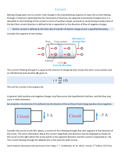
■ Contact Form
SPDT
SPST-NO
(Lead Wire Models Only)
SPST-NC
(Lead Wire Models Only)
COM
NO
NC
(Black) (Blue) (Red)
COM
(Black)
COM
NO
(Black) (Blue)
NC
(Red)
Note: Lead wire colors are indicated in parentheses.
■ Approved Standards
■ Contact Specifications
Consult your OMRON sales representative for specific models with
standard approvals.
UL1054 (File No. E41515)/CSA C22.2 No. 55 (UL approval)
Rated voltage
D2HW
125 VAC
0.1 A
12 VDC
2A
Item
Specification
Specification
Crossbar
Material
Gold alloy
Gap (standard value)
0.5 mm
Minimum applicable load
(see note)
1 mA at 5 VDC
Note: Minimum applicable loads are indicated by N standard
reference values. This value represents the failure rate at a
60% (λ60) reliability level (JIS C5003).
The equation λ60=0.5 x 10⁻⁶/operations indicates that a failure
rate of 1/2,000,000 operations can be expected at a reliability
level of 60%.
184
Sealed Subminiature Snap Action Switch
D2HW
Dimensions
■ Mounting Structure and Reference Positions for Operating Characteristics
Note: 1. All units are in millimeters unless otherwise indicated.
2. Dimensions not indicated in the diagrams have a tolerance of ±0.2 mm
3. The reference positions used for FP, OP, and TTP values are as shown below for each type of mounting.
Models without Posts
Models with Posts
M3-screw Mounting Models
D2HW-A@
D2HW-B@
D2HW-C@
1.7 dia.
1.7 dia.
0
3 −0.1
dia.
Reference
position
Reference
position
Reference
position
3.3±0.15 dia.
Mounting Hole Dimensions (Reference) Mounting Hole Dimensions (Reference)
2.4+0.1
0 dia. hole
(depth: 5 mm min.)
3 +0.1
0 dia. hole
(depth: 1.5 mm min.)
2.6
M3 tap
■ Terminals
Straight PCB Terminals
Angled PCB Terminals
Solder Terminals
3.5
Three-0.6
Three-0.6
Three-2
(3.1)
PCB Cutout Dimensions (Reference)
Three, 1 +0.1
0 dia. hole
PCB Cutout Dimensions (Reference)
2.4 +0.1
0 dia. hole
(depth: 5 mm min.)
2.6
Lead Wires Downwards
Three, 1+0.1
dia. hole
0
(12)
Lead Wires on Left-side
Lead Wires on Right-side
COM AVSS 0.5
(Black)
(12)
(13.3)
NO AVSS 0.5 (Blue)
NC AVSS 0.5 (Red)
See Note
(12)
(13.3)
Note: UL1007 AWG24 wires are used for UL/CSA approved models.
Angled terminal directions are shown below.
Left-angled terminal
Right-angled terminal
Sealed Subminiature Snap Action Switch
D2HW
185
■ Dimensions and Operating Characteristics
➡
Note: 1. All units are in millimeters unless otherwise indicated.
2. Dimensions not indicated in the diagrams below have a tolerance of ±0.2 mm.
3. The operating characteristics are for operation in the A direction (
).
Pin Plunger Models
Characteristic
D2HW-@20@@
A
1.7 dia.
Hinge Lever Models
t = 0.3 stainless
steel lever
A
Long Hinge Lever Models
A
t = 0.3 stainless
steel lever
Simulated Roller Hinge Lever Models
OT ref.
MD max.
1.4 mm (reference value)
0.25 mm
FP max.
OP
TTP max.
11.2 mm
10.4±0.2 mm
9.1 mm
A
15
t = 0.3 stainless
steel lever
Sealed Subminiature Snap Action Switch
D2HW
Models without
posts
7.2 mm
6.4±0.2 mm
5.1 mm
Models with posts
and M3-mounting
models
OF max.
RF min.
0.75 N {76 gf}
0.07 N {7 gf}
OT ref.
MD max.
1.6 mm (reference value)
0.5 mm
FP max.
OP
TTP max.
12.8 mm
11.5±0.5 mm
10 mm
Models without
posts
8.8 mm
7.5±0.5 mm
6 mm
Models with posts
and M3-mounting
models
OF max.
RF min.
0.5 N {50 gf}
0.03 N {3 gf}
OT ref.
MD max.
2.5 mm (reference value)
0.8 mm
FP max.
OP
TTP max.
15.5 mm
13.3±0.8 mm
11 mm
Characteristic
D2HW-@23@@
186
0.75 N {76 gf}
0.10 N {10 gf}
Characteristic
D2HW-@22@@
Models with posts
and M3-mounting
models
OF max.
RF min.
Characteristic
D2HW-@21@@
Models without
posts
Models without
posts
11.5 mm
9.3±0.8 mm
7 mm
Models with posts
and M3-mounting
models
OF max.
RF min.
0.65 N {66 gf}
0.05 N {5 gf}
OT ref.
MD max.
1.9 mm (reference value)
0.5 mm
FP max.
OP
TTP max.
16.5 mm
15.2±0.5 mm
13.5 mm
12.5 mm
11.2±0.5 mm
9.5 mm
➡
Note: 1. All units are in millimeters unless otherwise indicated.
2. Dimensions not indicated in the diagrams below have a tolerance of ±0.2 mm.
3. The operating characteristics are for operation in the A direction (
).
Hinge Roller Lever Models
Characteristic
D2HW-@24@@
4.8 dia. ×2.8
resin roller
A
8±0.1
(4.6)
15
FP OP
t=0.3 stainless
steel lever
(1.15)
TTP
3
Models with posts and
M3-mounting models
OF max.
RF min.
0.65 N {66 gf}
0.03 N {3 gf}
OT ref.
MD max.
1.9 mm (reference value)
0.6 mm
FP max.
OP
TTP max.
15.3 mm
14±0.6 mm
12.3 mm
(0.4)
6.5
Leaf Lever Models
Characteristic
D2HW-@26@@
A
t = 0.3 stainless
steel lever
Simulated Roller Leaf Lever Models
A
t = 0.3 stainless
steel lever
Long Leaf Lever Models
1.8 N {183 gf}
0.20 N {20 gf}
OT ref.
MD max.
1.8 mm (reference value)
0.5 mm
FP max.
OP
TTP max.
9.3 mm
7.4±0.5 mm
5.8 mm
A
20.85±1
t = 0.2 stainless
steel lever
3.3±0.15 dia.
Models with posts and
M3-mounting models
OF max.
RF min.
1.8 N {183 gf}
0.20 N {20 gf}
OT ref.
MD max.
2.0 mm (reference value)
0.5 mm
FP max.
OP
TTP max.
12.5 mm
10.8±0.5 mm
8.9 mm
Characteristic
D2HW-@28@@
(12)
OF max.
RF min.
Characteristic
D2HW-@27@@
Models with posts and
M3-mounting models
Models with posts and
M3-mounting models
OF max.
RF min.
0.9 N {92 gf}
0.05 N {5 gf}
OT ref.
MD max.
2.8 mm (reference value)
0.7 mm
FP max.
OP
TTP max.
19 mm
15.4±1.5 mm
12.8 mm
0
3 -0.1 dia.
COM AVSS 0.5
(Black)
NO AVSS 0.5 (Blue)
Note: UL1007 AWG24 wires are used for UL/CSA
approved models.
NC AVSS 0.5 (Red)
(13.3)
Sealed Subminiature Snap Action Switch
D2HW
187
Precautions
Be sure to read the precautions and information common to all Snap Action and Detection Switches, contained in the Technical User’s Guide,
“Snap Action Switches, Technical Information” for correct use.
■ Cautions
■ Correct Use
Degree of Protection
Mounting
IEC Publication 529, degree of protection IP67.
Turn OFF the power supply before mounting or removing the Switch,
wiring, or performing maintenance or inspection. Failure to do so may
result in electric shock or burning.
Do not use this product in water. Although molded lead wire models
satisfy the test conditions for the standard given below, this test is to
check the ingress of water into the switch enclosure after submerging
the Switch in water for a given time. Satisfying this test condition
does not mean that the Switch can be used in water.
Do not operate the Switch when it is exposed to water spray, or when
water drops adhere to the Switch surface, or during sudden temperature changes, otherwise water may intrude into the interior of the
Switch due to a suction effect.
Prevent the Switch from coming into contact with oil and chemicals.
Otherwise, damage to or deterioration of Switch materials may
result.
Do not use the Switch in areas where it is exposed to silicon adhesives, oil, or grease, otherwise faulty contact may result due to the
generation of silicon oxide.
Terminal Connection
When soldering the lead wire to the terminal, first insert the lead wire
conductor through the terminal hole and then conduct soldering.
Made sure that the capacity of the soldering iron is 30 W maximum.
Do not take more than 3 s to solder the switch terminal. Improper soldering involving an excessively high temperature or excessive soldering time may deteriorate the characteristics of the Switch.
When soldering the lead wire to the PCB terminal, pay careful attention so that the flux and solder liquid level does not exceed the PCB
level.
Side-actuated (Cam/Dog) Operation
For M3-screw mounting models, use M3 mounting screws with plane
washers or spring washers to securely mount the Switch. Tighten the
screws to a torque of 0.27 to 0.29 N·m. Exceeding the specified
torque may result in deterioration of the sealing or damage.
For models with posts, secure the posts by thermal caulking or by
pressing into an attached device. When pressed into an attached
device, provide guides on the opposite ends of the posts to ensure
that they do not fall out or rattle.
Mount the Switch onto a flat surface. Mounting on an uneven surface
may cause deformation of the Switch, resulting in faulty operation or
damage.
Operating Body
Use an operating body with low frictional resistance and of a shape
that will not interfere with the sealing rubber, otherwise the plunger
may be damaged or the sealing may deteriorate.
Handling
Do not handle the Switch in a way that may cause damage to the
sealing rubber.
When handling the Switch, ensure that pressure is not applied to the
posts in the directions shown in the following diagram. Also, ensure
that uneven pressure or pressure in a direction other than the operating direction is not applied to the Actuator as shown in the following
diagram. Otherwise, the post, Actuator, or Switch may be damaged,
or the service life may be reduced.
When using a cam or dog to operate the Switch, factors such as the
operating speed, operating frequency, push-button indentation, and
material and shape of the cam or dog will affect the durability of the
Switch. Confirm performance specifications under actual operation
conditions before using the Switch in applications.
IEC Publication 529, degree of protection IP67.
Wiring Molded Lead Wire Models
When wiring molded lead wire models, ensure that there is no weight
on the wire or that there are no sharp bends near the parts where the
wire is drawn out. Otherwise, damage to the Switch or deterioration
in the sealing may result.
Using Micro Loads
Even when using micro load models within the operating range,
inrush currents or surges may decrease the life expectancy of the
Switch. Therefore, insert a contact protection circuit where necessary.
188
Sealed Subminiature Snap Action Switch
D2HW
MEMO
Sealed Subminiature Snap Action Switch
D2HW
All sales are subject to Omron Electronic Components LLC standard terms and conditions of sale, which
can be found at http://www.components.omron.com/components/web/webfiles.nsf/sales_terms.html
ALL DIMENSIONS SHOWN ARE IN MILLIMETERS.
To convert millimeters into inches, multiply by 0.03937. To convert grams into ounces, multiply by 0.03527.
OMRON ON-LINE
OMRON ELECTRONIC
COMPONENTS LLC
Global - http://www.omron.com
USA - http://www.components.omron.com
55 E. Commerce Drive, Suite B
Schaumburg, IL 60173
847-882-2288
Cat. No. X303-E-1
11/10
Specifications subject to change without notice
Sealed Subminiature Snap Action Switch
D2HW
Printed in USA


© Copyright 2026