
Aeria 10 Pro - Aeda Healthcare
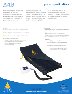
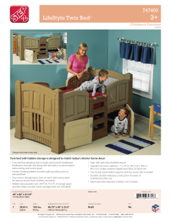
U S E R
G U I D E
Key
Definition of symbols used
User guide
- medium
- high
i
Important information
Iron - low
Do not iron
Caution symbol
CL
Bleach - chlorine
Electrical hazard
Do not bleach
BLEACH
Aeda – a brand actively
supporting your health
- medium
- high
Zip located here
Do not immerse control unit
Infection control
Do not ...
Alternating mode
Static mode
Do not tumble dry
Audio alarm - off
If dry cleaning - do not use a
solution stronger than
perchloroethane
Serial number
Operating instructions
OROETH
HL
P
Maximum water temperature
(in this example - 160°F 70ºC)
Control unit
Medical equipment mattress
system with respect to electrical
shock, fire and mechanical hazards
only; in accordance with UL60601-1
and CANCSA N22.2 NO. 601.1
Disposal: Do not dispose of this
product as unsorted municipal
waste. Collection of such waste
separately for special treatment is
necessary.
Symbol for ”Authoristed Representative in
the European Community”
CE Marking (European UnionNew Approach Directives)
Audio alarm
Mattress overlay
Wash instruction here
Manufacturer details
70
Power
E
AN
The Aeda mattress
and seating category
Type B Applied Part
Tumble dry - low
PER
C
A fresh approach to proven
pressure care solutions
Class II Equipment
key
Aeria 10 Pro User Guide
Contents
System overview
2
System features
3
Intended use
4
Safety5
Protection against hazards
5
System set up
6
Dismantling the system
7
Operation8
Control unit layout
8
Establishing pressure
9
Alarm11
Care and cleaning
12
Troubleshooting 13
Specifications15
Warranty20
Aeda - Actively supporting your health contentspage 1
System overview
Introducing the Aeria 10 Pro Mattress
Replacement System – this chapter
provides a basic system overview, intended
use guidelines and a summary of system
features and box contents.
•
dynamic mattress replacement with
four air hoses and CPR release handle
•
•
•
•
•
digital control unit with transport cap
•
carry bag
power cord
straps
360° zip
Aeria 10 Pro Pro User Guide
mattress top cover
Aeria 10 Pro Pro Quick Set Up Guide
mattress base
square hanging hooks
(optional spare part)
four hoses
Applied part.
The mattress is treated as an applied part.
premium bag (in the EU)
page 2
system overview
basic bag (in the US)
Aeria 10 Pro User Guide
Introducing the Aeria 10 Pro Mattress Replacement System, this chapter provides a basic system
overview, intended use guidelines and a summary of system features and box contents.
•
•
•
the Aeria 10 Pro is indicated for the
prevention and treatment of skin
breakdown and pressure ulcers in
patients at high risk
constructed from 19 transverse cells –
10 inch 265 mm high – that cyclically
inflate and deflate in an alternating
pattern, providing gentle and dynamic
support
cyclic alternation of pressure prevents
arterial and venous capillary occlusion
in the patient’s surface tissue –
maintaining and stimulating the flow of
blood and lymphatic fluids through
these tissues to provide essential
oxygen and remove metabolic waste
•
suitable for use at home or in long term
or extended care environments
•
the system is designed to replace your
existing single bed mattress, for use on
top of a standard single bed frame
•
•
•
the three-cell cycle provides increased
patient support, allowing more body
surface to be supported at any one time
for optimum healing
connected to the control unit via four air
hoses, mattress cells are inflated by an
electronic control unit, which includes a
pressure sensor for monitoring
mattress pressure and adjustable
pressure settings to match patient
weight and comfort needs
•
an inner static cell (cell in cell design)
remains fully inflated at all times to
prevent patients ‘bottoming out’ and
provide added safety when mattress is
inclined or in the event of a power
interruption
air pressure in the mattress
replacement is continually monitored
and a visual and audible alarm activates
in the event mattress pressure becomes
too low or high
•
operator controls are kept to a minimum
for simplicity and ease of use
•
visible and audible alarm (plus alarm
mute) to warn of a pressure failure
System features
Support
• 19 x 10” 265 mm high density alternating
cells
•
•
cell in cell design (internal static cell
that remains fully inflated at all times) to
prevent ‘bottoming out’ and provide
added safety when mattress is inclined
or in event of power interruption
vapor permeable, waterproof top cover
prevents moisture transfer, while
multi-stretch fabric minimizes friction
and reduces shear
•
•
adjustable pressure level to match users
weight and comfort needs
fully adjustable support straps and non
slip mat securely fastens system to any
standard single bed frame
•
•
static pillow for stable head support and
optimal comfort
quick release CPR tag conveniently built
into the digital control unit
•
•
supporting users to a maximum weight
of 440 pounds 200 kilograms
tape sealed seams for maximum
antibacterial protection
•
reinforced air hoses prevent unwanted
kinks or interference to air flow
•
timed transport and static function
for stable patient handling, transfer
and nursing care (20 minute
automatic cutout)
Safety
• 1 in 3 cell alternation sequence
for ‘zero’ pressure benefits
Aeda - Actively supporting your health Simplicity
• easy to operate digital touch panel
with bright LED indicators
•
quick connector air hose attachments
with interconnecting transport cap
•
360 degree quick release zipper to assist
in cleaning (remove the cover from a
stationery position)
•
control unit includes inbuilt rear
hanging hooks on for easy mounting
and system portability; two size options
to match different size bed ends
system overviewpage 3
Intended use
Indications
Connecting the system to other devices
The Aeria 10 Pro Mattress Replacement
System is indicated for:
There are other devices necessary for
normal operation.
•
The Aeria 10 Pro mattress replacement can
be fitted to most standard hospital or single
bed bases.
the prevention and treatment of skin
breakdown and pressure ulcers in
patients of high risk
Contraindications
Patient conditions for which the application
of pressure relief therapy on the Aeria 10 Pro
Mattress Replacement System is
contraindicated include:
•
•
instable spinal cord injury
The Aeria 10 Pro digital control unit can be
fitted to the foot or head board of most
hospital or home care beds.
Alternatively, the control unit can be placed
on the floor, underneath the bed or on any
other stable surface.
cervical traction
The Aeria 10 Pro Mattress Replacement
System is an aid to the prevention and
management of pressure ulcers. If there is
no improvement in the patient’s condition,
clinical advice should be sought.
Therapeutic devices should only be used in
accordance with manufacturer’s
instructions and under the consent,
supervision and management of a suitably
qualified health professional.
Aeda Healthcare accepts no liability for any
use, change or assembly of the product
other than that stated in this User Guide.
Intended care setting
Intended care settings for the Aeria 10 Pro
Mattress Replacement System are:
•
•
long term or extended care
home care
Working conditions
•
•
Temp: 50°F - 105°F 10°C – 40°C
Humidity: 30% ~ 75%
Shipping / Storage conditions
•
•
Temperature: 15°F - 140°F -10°C –60°C
Humidity: 10% ~ 80%
page 4
intended use
Aeria 10 Pro User Guide
Safety
This chapter provides general safety precautions
and recommended patient specifications.
General safety precautions
Protection against hazards
For your own safety and the safety of
equipment, always take the following
precautions:
Fluids
•
Before commencing set up or
installation, ensure the power is
switched off and disconnect the power
cord from the control unit.
•
Unplug the system from the supply
mains to disconnect its circuits.
•
Placing layers between patient and seat
cushion should be avoided or kept to a
minimum. As part of sensible pressure
care, avoid wearing clothing that may
cause areas of localized damage due to
creases, seams, objects in pockets, etc.
•
Never use sharp objects or electrically
heated blankets on or under the system.
•
Product top cover is not completely air
permeable and may present a
suffocation risk. It is the responsibility of
the caregiver to ensure that the patient
can use this product safely.
•
Avoid blocking the air intakes of the
control unit, located at the rear of the unit.
•
Only the control unit and mattress
combination as indicated by Aeda
Healthcare should be used, otherwise
the correct function of the product
cannot be guaranteed.
Maximum patient weight
The maximum recommended patient
weight for this system is 440 pounds
200 kilograms.
Aeda - Actively supporting your health Avoid spilling fluids on any part of the
control unit. If spills do occur:
•
•
Turn off control unit power and
disconnect the unit from the main
electricity supply.
Immediately clean fluids from the
casing by wiping with a soft cloth.
Ensure there is no moisture in or near
the power inlet, power switch and
power cord before reconnecting the
power supply.
Do not position the system so that it is
difficult to operate the disconnection
device.
Check the operation of controls and
other components around the spill area.
Fluid or liquid remaining on the
electronic controls can cause corrosion
that may cause the electronic
components to fail. Component failures
may cause the unit to operate
erratically, possibly producing
potential hazards to patient and carers.
Explosion hazard
Equipment is not suitable for use in the
presence of a flammable anesthetic
mixture with air, oxygen or nitrous
oxide.
•
Do not use in the presence of smoking
materials or open flame – air flowing
through the mattress will support
combustion.
•
Do not open the control unit – risk of
electrical shock. Refer servicing to
qualified service personnel.
•
Do not modify this system without the
authorization of the manufacturer.
Disposal
At the end of useful life, dispose of all
components (air filter, air cells, mattress
cover and base) according to local
procedures and regulations or contact your
local Aeda Healthcare authorized dealer for
advice.
Power cord
The system should never be operated with a
worn or damaged power cord. Should the
power cord be found to be worn or damaged,
contact your local Aeda Healthcare
authorized dealer for a replacement.
Interference
Significant risks of reciprocal interference
may be posed by the presence of the system
during specific investigations or treatments.
Potential electromagnetic or other
interference between the system and other
devices may occur. If interference is
suspected, move equipment from sensitive
devices of contact the manufacturer.
safetypage 5
System set up
Preparing the system for use
Carefully unpack the system and locate all
items shown in the picture below.
Inspect each item for any damage that may
have occurred during shipping. Any damage
or missing components should be reported
to your local Aeda Healthcare authorized
dealer as soon as possible.
Attach to the bed by securing the
adjustable straps, located on the
underside of the mattress base under
each bed end. Ensure the strap buckles
are securely fastened together and the
straps are pulled tight.
mattress replacement
(top cover & base)
Do not secure mattress straps to bed
side rails – straps will tear.
control unit
power cord
1.Remove your existing mattress and
place the mattress replacement on top
of your bed – printed top cover facing
upwards and air hoses towards the base
of the bed.
page 6
Ensure the control unit is firmly
secured to the bed. Failure to do so
could result in equipment damage.
Before attaching the control unit to the
floor or the foot board of the bed,
ensure they are sufficiently robust and
free of damage.
3.Attach all four air hoses to the control
unit with the handle – the four
connectors simply press into place.
Ensure the handle is firmly pressed on
before switching on the power.
Ensure that straps do not interfere with
the operation of the bed, and that the
mattress is properly secured. Failure to
do so could result in patient injury or
equipment damage.
2.Hang the control over the foot end of
your bed, using
the inbuilt
hanging hooks.
The control unit
can also be
placed on a flat
surface (ie on the
floor or
underneath the
bed).
system set up
Aeria 10 Pro User Guide
This chapter describes the steps necessary
to prepare the Aeria 10 Pro system for use.
Straighten any twists in the air hoses to
ensure uninterrupted air flow between
the control unit and mattress. Also
ensure the hoses are not trapped
between the mattress and bed. Failure
to do so could result in an under inflated
mattress leading to patient injury.
5.Insert the power cord into the base of
the control unit, then plug into an
appropriate electrical outlet and switch
on mains power.
1. Switch off the control unit.
2.Press the Alarm Mute button
to silence the audible alarm.
3.Switch off mains power and unplug the
power cord from the mains outlet.
2
3
1
6.On the control unit, press the Power
button to switch on.
4.Before inflating, unzip the top cover to
ensure the cells are straight and the cell
straps are not twisted. Rezip the top
cover.
Dismantling the system
The Pressure Setting indicators
(Soft to Hard) flash to indicate the
system is operational and inflating.
Allow up to 50 minutes for complete
inflation.
4.Remove the handle from the control
unit. This will deflate all cells, including
the three static head cells and side
bolsters.
5.Once air has been released from the
system, detach the mattress from your
bed by unfastening the straps, then fold
and roll the mattress for storage.
6.Return all items to the custom carry bag
for safe keeping.
Do not store the system
in direct sunlight.
When initial inflation is complete, the
first two Pressure Setting indicators will
illuminate, together with the Alternating
Mode indicator, to indicate the system is
ready for use (the system automatically
defaults to Alternating Mode on startup).
SOFT
MODE
SOFT
MODE
POWER
POWER
7.Once the mattress is fully inflated,
bedding can be replaced. Secure sheets
loosely enough to ensure they do not
interfere with cell alternation.
Aeda - Actively supporting your health system set uppage 7
Operation
Control unit layout
Alarm mute
Silences the audible alarm (on / off).
Mode button
Alternating / Static indicators
Switches between Static
and
Alternating
operational
modes.
The red Static Mode indicator
illuminates when mattress is
operating in static mode (all cells fully
inflated with no dynamic alternation).
The red Alternating Mode indicator
illuminates when the mattress is
operating in dynamic alternating
mode (alternative cells cyclically
inflating and deflating).
Pressure button
Pressure Setting indicators
Power button
Turns system power on and off.
Alarm indicator
This red light flashes, and an audible
alarm signal sounds, to alert when
control unit or mattress replacement
pressure fails.
page 8
The alarm has five different signals,
identified by five different flash
sequences, to indicate the cause of
the failure.
See page 11 Alarm function for
details of each alarm signal and an
illustration of each flash sequence.
The audible alarm also sounds when
the power to the control unit is
switched off – press the Mute button
to silence.
operation
Cycles mattress pressure from Soft
through to Hard (low to high), in line
with patient weight and comfort
requirements. The Pressure Setting
indicators illuminate to indicate
which of the four settings is
operational.
The system automatically reverts to
the maximum setting (Hard) when
Static Mode is selected.
Note:
No special skills, training or knowledge
are required to operate the control unit.
Aeria 10 Pro User Guide
This chapter describes how to safely operate the Aeria 10 Pro system
including patient set up and control unit function.
Establishing pressure (lying)
Establishing pressure (inclined)
1.Prepare the system for use as described
in System Set Up. When initial inflation
is complete, the first two Pressure
Setting indicators illuminate, together
with the Alternating Mode indicator, to
indicate the system is ready for use (with
Alternating Mode as default setting).
When moving the patient to a sitting or more
upright position, pressure should be
increased to provide added support and to
avoid ‘bottoming out’. It is recommended
the maximum pressure setting (Hard) be
selected while the patient is semirecumbent (sitting or inclined).
Always return to the original
pressure setting when patient
returns to a lying position.
2.Cover loosely with a sheet before placing
patient on the mattress.
The patient may lie on the Aeria 10 Pro
system during inflation however the
mattress will fill faster if allowed to
inflate first.
3.When the patient is lying comfortably,
press the Pressure button to cycle
through the four available pressure
settings (Soft through Hard), to test the
desired setting for effective patient
comfort and support. Before lowering
the pressure, ensure the Aeria 10 Pro
system is working effectively by
performing a ‘bottoming out’ test
(a test to ensure the patient is adequately
suspended away from the base).
‘Bottoming out’ test
a. With the patient lying in the supine
position (lying on back, face upwards),
unzip one side of the top cover, just
past the sacral region (lower spine).
b. Slide your hand underneath the
patient and feel for a deflated cell
under the patient’s lower spine.
Remember that the inner static cell
will remain inflated however your
hand should easily slide between
patient and base.
Aeda - Actively supporting your health c. If the patient is adequately
suspended, the pressure setting can
be lowered. After approximately 12
minutes, reassess system function
and patient comfort.
If pressure fails for whatever reason
the red Alarm indicator will display
and audible alert will sound –
immediately increase pressure to the
maximum pressure setting (Hard).
After lowering the pressure setting,
always check the Aeria 10 Pro system
is working effectively. Failure to do so
could cause patient injury.
Wait at least 12 minutes between any
pressure adjustment or patient
assessment as the Aeria 10 Pro system
may take a full cycle to adjust to the
new pressure setting.
i
A “control setting guide”
is included on the side
of the control unit, to
provide a quick
reference for
recommended
weight setting.
These settings
are a guide
only. Always
verify pressure
settings with a
‘bottoming out’
test.
If parts need to be repaired, circuit
diagrams and a list of component parts
can be provided by the manufacturer.
operationpage 9
Operation
Mode
In Static Mode, all mattress cells remain
fully inflated to maximum pressure setting,
thereby terminating the alternation cycle
and any therapeutic patient benefits. This
mode should be used to create a firm base
for stable patient handling and transport or
other special circumstances.
In Alternating Mode, alternate mattress
cells inflate and deflate following a fixed
cycle time of 10 to 12 minutes, with the
exception of three static head cells.
Alternating mode is used for normal
therapeutic function.
i
i
The system will automatically start in
Static Mode, and revert to Alternating
Mode once operational pressure is
reached.
he system will operate in Static Mode
T
for a maximum of 20 minutes, after
which it will automatically revert to
Alternating Mode for patient safety.
The Aeria 10 Pro system provides no
therapeutic benefits when operating in
Static Mode. Transport function
1.Before patient transport, press the
Static Mode button and wait at least 12
minutes for cells to inflate to maximum
pressure.
2.Once mattress pressure has reached
maximum inflation, press the Power
button to switch off the control unit.
Switch off mains supply and unplug the
power cord.
page 10
3.Remove the rapid release handle from
the control unit and allow air to escape
for a few seconds before inserting the
transport cap into the handle air outlets
to seal the system. This release softens
the mattress surface for pressure relief
and comfort. Ensure the cap is firmly
secured across all four air hose outlets.
The length of time the system remains
inflated during transport will depend
on the weight and height of the patient,
and will vary on a case by case basis.
CPR / Re-inflation
Rapid deflation of the mattress replacement
may be necessary for emergency treatment
(or to decommission the unit).
If emergency treatment is required, firmly
pull the rapid release CPR tag. Removing
the tag will rapidly deflate the entire system,
including side bolsters in less than 10
seconds.
uring transport, regularly perform a
D
‘bottoming out’ test (see page 9) to
ensure the patient is adequately
suspended on the mattress. Failure to
do so could cause patient injury.
Once the handle has been removed, the
control unit must be switched off before
the handle is replaced and the system
restarted.
To attach the handle to the control unit:
1.Depress the lever on top of the handle.
2.Aligning the ports on the handle with
those on the control unit, firmly push the
handle into position.
3..Release the lever, ensuring this has
engaged onto the catch connected to the
control unit.
nce the CPR tag has been removed,
O
the control unit must be switched off
before the CPR tag is replaced and the
system restarted.
To reinflate the system after the rapid
release CPR tag has been removed, turn off
power to the control unit and replace the
CPR tag.
Once firmly connected, switch on power and
wait for the system to gain optimal pressure.
To detach the handle from the control unit:
1.Depress the lever on top of the handle.
2.Pull the handle away from the control
unit.
operation
Aeria 10 Pro User Guide
Alarm function
The red Alarm indicator flashes, and an
audible alert sounds, to indicate control
unit or mattress pressure has failed. The
indicator will remain illuminated until
appropriate pressure is restored. The
audible alarm can be silenced by pressing
the Alarm Mute button.
The system has five different alarm signals,
identified by five different Pressure Setting
illumination sequences. The signals and
corresponding Pressure Setting indicators
displays are illustrated below.
Pressure setting display
Alarm signal
To guard against the control unit being
accidentally shut off, the audible alarm will
sound whenever power to the unit is
switched off. Press the Alarm Mute button to
silence.
If the Alarm activates and the system fails to
inflate or loses pressure, refer to page 13
Troubleshooting for further support.
Initial failure
Mattress has failed to reached minimum
operational pressure within 50 minutes of
switching on the power
Pressure too low
Pressure has fallen 10 mmHg or more below
the minimum operational requirements for
the selected setting
Pressure too high
Pressure has exceeded the maximum
setting for therapeutic benefit
Alternating mode failure
The mattress has failed
to commence alternation
If the problem persists, contact your
local Aeda Healthcare authorized
dealer for further advice about repair.
Do not try to open the control unit.
Opening the unit could cause personal
injury or equipment damage.
i
These alarm signals
also appear on the side
of the control unit for
quick reference.
AC power failure
No pressure output due
to mains power failure
Aeda - Actively supporting your health operationpage 11
Care & cleaning
To prevent cross contamination, the
mattress should be examined and
disinfected between patient use.
Clean the mattress in accordance with
local infection control policy and
government regulations for blood
borne pathogens. Failure to do so could
cause patient or personal injury.
The mattress is not protected against
excessive amounts of water.
Disconnect power supply before
cleaning. Failure to do so could result
in equipment damage or electric shock.
Do not use high temperature autoclave
steam cleaning devices or phenolicbased products for cleaning. This could
result in damage to the equipment and
loss of waterproof qualities of the top
cover.
Switch off and disconnect the control
unit from mains power supply before
cleaning. Do not immerse the control
unit in water.
Cleaning & infection control
It is recommended that the system be
cleaned regularly if in constant use.
This chapter describes general care and cleaning for the
Aeria 10 Pro system, including basic maintenance procedures.
10,000 ppm available chlorine).
Dry thoroughly before refastening.
Do not machine wash the overlay base.
Top cover cleaning
Unzip the top cover from the base before
washing. For basic care and cleaning, wipe
down with warm water containing
detergent. The top cover can also be
machine washed at 160°F 70ºC.
For infection control, swab with a
solution of sodium hypoclorite or similar
(up to 10,000 ppm available chlorine).
Dry thoroughly before use.
Refer to the top cover wash tag for cleaning
instructions.
Do not use system without top cover.
Control unit external cleaning
Disconnect control unit from mains power
before cleaning. Gently wipe down the
external case, including CPR handle, with a
soft cloth.
Soak the cloth in warm water containing
detergent, and twist dry any excess water
before use. Repeat the process with a dry
cloth to remove excess moisture.
Ensure the control unit is disconnected
from mains electricity before cleaning.
Base cleaning
Disinfection
Should the base require cleaning deflate the
mattress, disconnect air cells from the base
by unfastening the press studs at each end.
Remove double tubing from main base air
tubes and slide the cell out from the cell
straps. Swab the cell with a solution of
sodium hypoclorite or similar (up to
The mattress, top cover and control unit may
be decontaminated by using ETO (Ethylene
Oxide).
page 12
Periodic maintenance
Care should be taken to avoid the risk of
electric shock when changing the air filter
and fuse.
care & cleaning
Air filter replacement
1.Switch off power supply to the control
unit and disconnect the air hoses and
power cord.
2.Place the control unit face down on a
soft, flat surface with back panel
uppermost (use a soft cloth to prevent
scratches).
3.Use a small screwdriver to carefully
remove the air filter cover. Clean the
dust from the filter or discard and
replace with a new filter.
4.Refit the air filter cover to the control
unit before use.
It is recommended that the air filter
be replaced each year. Replacement air
filters are available from your local
Aeda Healthcare authorized dealer.
Fuse replacement
1.Switch off power supply to the control
unit and remove the power cord from the
socket in the base of the unit.
2.Insert a small screwdriver into the
groove and turn anti-clockwise (quarter
turn).
3.Remove the ‘blown’ fuse from the fuse
holder clip and discard.
4.Insert a new fuse into the plug. Push
against the force of the spring and turn
clockwise with the screwdriver (quarter
turn).
When changing the replaceable fuse,
use same rating fuse only (T1AL/250V).
Preventive inspections and calibration
are not required.
Aeria 10 Pro User Guide
Troubleshooting
This chapter provides basic troubleshooting
support for the Aeria 10 Pro system.
Problem
Cause
Solution
Control unit does not
operate; no display
lights are illuminated.
The control unit may
not be attached to a
power source or a fuse
may need replacing.
1.Check the control unit is connected to mains
power outlet with the correct voltage.
2.Check the control unit is switched on.
Switch off and unplug the unit before restarting.
3.Check the mains plug fuse first (3 AMP) then check both control unit fuses
(1 AMP) – fuses can be released using a screwdriver.
Do not try to open the control unit. Opening the unit
could cause personal injury or equipment damage.
Alarm LED
Initial failure
1. Reset the alarm – turn off Power and press the Alarm Mute button.
2.Check all hoses along the inside of the mattress – each should be firmly
connected. Check each air cell is securely attached to the connecting air pipe.
+ audible alarm
3. Check all cells, pipes and hoses for any air leakage.
4.Switch on Power (system automatically starts in Static Mode and
will switch to Alternating Mode when operational pressure is reached).
Alarm LED
Pressure too low
1. Reset the alarm – turn off Power and press the Alarm Mute button.
2.Check the CPR handle is intact, ensuring all four sealing
connectors are fully fitted to the control unit.
3.Check all hoses along the inside of the mattress – each should be firmly
connected. Check each air cell is securely attached to the connecting air pipe.
+ audible alarm
4. Check all cells, pipes and hoses for any air leakage.
5. Check that the air filter cover is secured correctly and the air filter is clean.
6.Switch on Power (system automatically starts in Static Mode
and will switch to Alternating Mode when operational pressure is reached).
Alarm LED
Pressure too high
1. Reset the alarm – turn off Power and press the Alarm Mute button.
2.Remove the rapid release CPR handle to reduce system pressure
– reconnect when pressure has decreased.
+ audible alarm
3. Check for twists in the air hoses between mattress and control unit.
4.Switch on Power (system automatically starts in Static Mode
and will switch to Alternating Mode when operational pressure is reached).
Aeda - Actively supporting your health troubleshooting page 13
Troubleshooting
Problem
Cause
Solution
Alarm LED
Alternating Mode
failure (no alternation)
1. Reset the alarm – turn off Power and press the Alarm Mute button.
+ audible alarm
Alarm LED
2.Remove the rapid release CPR handle to reduce system pressure
– reconnect when pressure has decreased.
3.Switch on Power (system automatically starts in Static Mode and
will switch to Alternating Mode when operational pressure is reached).
AC power failure
1. Press the Alarm Mute button to silence audible alert.
2.Check the power cord is firmly plugged into the mains power outlet and
the control unit plug; and check that mains power is switched on.
i
+ audible alarm
Patient is sinking or
‘bottoming out’ while
lying flat on the
mattress
The pressure may be
set too low for the
patient’s weight
If power is restored within 20 minutes of failure, the system
will run initial start up phase before returning to the last setting.
1. Increase pressure to maximum setting (Hard)
2.Check effective system performance by conducting a ‘bottoming out’
test as described on page 9.
If the problem cannot be resolved, please contact your local Aeda Healthcare authorized dealer for further support.
page 14
troubleshooting
Aeria 10 Pro User Guide
Specifications
This chapter provides the various physical and technical specifications of
the Aeria 10 Pro system, including details of replacement parts.
Technical specifications
Classification
Equipment not suitable for use in the presence of a flammable
anesthetic mixture with air, oxygen or nitrous oxide.
Non-continuous operation
Type B Equipment
Control unit
Class II Equipment
Type
Ordinary Equipment
Maximum recommended
patient weight
Dimensions11.5” x 5.5” x 10.5”
290 x 140 x 270 mm
440 lb 200 kg
Weight
Risk category
High to very high
Rated voltage:
Mattress replacement
Dimensions (inflated):
Digital
7.7 lb 3.5 kg
US
110-120VAC 50/60Hz 0.2A
EU
220 - 240VAC 50/60Hz 0.2A
US, EU wide
80” x 35” x 10”
2000 x 880 x 280 mm
Rated input power
20 va
Protection class
Class 2
EU narrow
80” x 32” x 10”
2000 x 830 x 280 mm
Power cord length
16 ft 5 m
Air output (Lpm)
8
Weight
27.5 lb 12.5 kg
Cycle time (mins)
10 -12
Number of cells19
Cell height10” 265 mm
Alternation type
1 in 3
System part numbers
Cell material
TPU coated nylon
Aeria 10 Pro Mattress Replacement System:
Base material
TPU coated nylon
US:
MT-A3-015
EU wide: MT-A3-115
EU narrow: MT-A3-225
Top cover materialPU coated
multi-stretch polyester
Cover attachment
Quick release zipper
Aeria 10 Pro Control Unit:
Skirt seams
RF welded
US:
MT-S4-025
EU:
MT-S4-020
Aeria 10 Pro Mattress:
Aeda - Actively supporting your health US:
MT-S4-115
EU wide:
MT-S4-115
EU narrow:
MT-S4-150
specifications page 15
Specifications
This chapter provides the various physical and technical specifications of
the Aeria 10 Pro system, including details of replacement parts.
Electromagnetic emissions for all Aeria EQUIPMENT and SYSTEMS
Guidance and manufacturer’s declaration – electromagnetic emission
The Aeria 10 Pro is intended for use in the electromagnetic environment specified below. The customer or the
user of the Aeria 10 Pro should ensure that it is used in such an environment.
Emission test
Compliance
Electromagnetic environment – guidance
RF emissions
Group 1
The Aeria 10 Pro uses RF energy only for its
internal function. Therefore, its RF emissions are
very low and are not likely to cause any interference
in nearby electronic equipment.
Class B
The Aeria 10 Pro is suitable for use in
all establishments, including domestic
establishments and those directly connected to
the public low-voltage power supply network that
supplies buildings used for domestic purposes.
CISPR 11
RF emission
CISPR 11
Harmonic emissions
Class A
IEC 61000-3-2
Voltage fluctuations/ flicker
emissions
Complies
IEC 61000-3-3
page 16
specifications
Aeria 10 Pro User Guide
Specifications
This chapter provides the various physical and technical specifications of
the Aeria 10 Pro system, including details of replacement parts.
Declaration – electromagnetic immunity
Guidance and manufacturer’s declaration – electromagnetic immunity
The Aeria 10 Pro is intended for use in the electromagnetic environment specified below. The customer or the user of the Aeria 10 Pro
should ensure that it is used in such an environment.
Immunity test
IEC 60601 test level
Compliance level
Electromagnetic environment – guidance
Electrostatic
discharge (ESD)
±6 kV contact
±6 kV contact
±8 kV air
±8 kV air
Floors should be wood, concrete or ceramic tile. If floor are
covered with synthetic material, the relative humidity should
be at least 30%.
±2 kV for power supply
lines
±2kV for power supply
lines
Mains power quality should be that of a typical commercial or
hospital environment.
Surge IEC
61000-4-5
± 1 kV line(s) to line(s)
±1 kV differential mode
Mains power quality should be that of a typical commercial or
hospital environment.
Voltage dips,
short interruptions and voltage
variations on
power supply
input lines
<5% UT (>95% dip in UT)
for 0.5 cycle
<5% UT (>95% dip in UT)
for 0.5 cycle
40% UT (60% dip in UT)
for 5 cycles
40% UT (60% dip in UT)
for 5 cycles
70% UT (30% dip in UT)
for 25 cycles
70% UT (30% dip in UT)
for 25 cycles
Mains power quality should be that of a typical commercial or
hospital environment. If the user of the Aeria 10 Pro requires
continued operation during power mains interruptions, it
is recommended that the Aeria 10 Pro be powered from an
uninterruptible power supply or a battery.
<5% UT (>95% dip in UT)
for 5 sec
<5% UT (>95% dip in UT)
for 5 sec
IEC 61000-4-2
Electrical fast
transient/burst
IEC 61000-4-4
EC 61000-4-11
Power frequency 3A/m
(50Hz) magnetic
field
3A/m
Power frequency magnetic fields should be at levels
characteristic of a typical location in a typical commercial or
hospital environment.
IEC 61000-4-8
NOTE: UT is the a.c. mains voltage prior to application of the test level.
Aeda - Actively supporting your health specifications page 17
Specifications
This chapter provides the various physical and technical specifications of
the Aeria 10 Pro system, including details of replacement parts.
Declaration – electromagnetic immunity – for Aeria EQUIPMENT and SYSTEMS that are not LIFESUPPORTING
Guidance and manufacturer’s declaration – electromagnetic immunity
The Aeria 10 Pro is intended for use in the electromagnetic environment specified below. The customer or the user of the Aeria 10 Pro
should ensure that it is used in such an environment.
Immunity
test
IEC 60601
test level
Compliance
level
Electromagnetic environment - guidance
Conducted
RF
3 Vrms
3 Vrms
Portable and mobile RF communications equipment should be used no closer to any part of
the CT515, including cables, than the recommended separation distance calculated from the
equation applicable to the frequency of the transmitter
IEC 610004-6
150 kHz to
80 MHz
Recommended separation distance
d = 1.167√P
Radiated
RF
IEC 610004-3
3 V/m
80 MHz to
2.5 GHz
3 V/m
d = 1.167√P
80 MHz to 800 MHz
d = 2.333√P
800 MHz to 2.5 GHz
Where P is the maximum output power rating of the transmitter in watts (W) according to the
transmitter manufacturer and d is the recommended separation distance in meters (m).
Field strengths from fixed RF transmitters, as determined by an electromagnetic site survey,a
should be less than the compliance level in each frequency range.b
Interference may occur in the
vicinity of equipment marked
with the following symbol:
NOTE 1: At 80 MHz and 800 MHz, the higher frequency range applies.
NOTE 2: These guidelines may not apply in all situations. Electromagnetic propagation is affected by absorption and reflection from
structures, objects and people.
a. Field strengths from fixed transmitters, such as base stations for radio (cellular/cordless) telephones and land mobile radios, amateur
radio, AM and FM radio broadcast and TV broadcast cannot be predicted theoretically with accuracy. To assess the electromagnetic
environment due to fixed RF transmitters, an electromagnetic site survey should be considered. If the measured field strength in the
location in which the Aeria 10 Pro is used exceeds the applicable RF compliance level above, the Aeria 10 Pro should be observed to verify
normal operation. If abnormal performance is observed, additional measures may be necessary, such as reorienting or relocating the
Aeria 10 Pro.
b. Over the frequency range 150 kHz to 80 MHz, field strengths should be less than 3 V/m.
page 18
specifications
Aeria 10 Pro User Guide
Specifications
This chapter provides the various physical and technical specifications of
the Aeria 10 Pro system, including details of replacement parts.
Recommended separation distances between portable and mobile RF communications
equipment and the EQUIPMENT or SYSTEM – for Aeria EQUIPMENT and SYSTEMS that
are not LIFE-SUPPORTING
Recommended separation distances between portable and mobile RF communications equipment and the Aeria 10
Pro Alternating Control Unit
The Aeria 10 Pro is intended for use in an electromagnetic environment in which radiated RF disturbances are controlled. The
customer or the user of the Aeria 10 Pro can help prevent electromagnetic interference by maintaining a minimum distance
between portable and mobile RF communications equipment (transmitters) and the Aeria 10 Pro as recommended below,
according to the maximum output power of the communications equipment.
Rated maximum
output power of
transmitter (W)
Separation distance according to frequency of transmitter (m)
150 KHz to 80 MHz
80 MHz to 800 MHz
800 MHz to 2.5 GHz
d = 1.167√P
d = 1.167√P
d = 2.333√P
0.01
0.117
0.117
0.233
0.1
0.369
0.369
0.738
1
1.167
1.167
2.333
10
3.689
3.689
7.379
100
11.667
11.667
23.333
For transmitters rated at a maximum output power not listed above, the recommended separation distance d in meters
(m) can be estimated using the equation applicable to the frequency of the transmitter, where P is the maximum output
power rating of the transmitter in watts (W) according to the transmitter manufacturer.
NOTE 1: At 80 MHz and 800 MHz, the separation distance for the higher frequency range applies.
NOTE 2: These guidelines may not apply in all situations. Electromagnetic propagation is affected by absorption and
reflection from structures, objects and people.
Aeda - Actively supporting your health specifications page 19
Warranty
Aeda Healthcare Ltd warrants each of its
products to perform in accordance with
established specifications for specified time
periods, starting from the date the product
is shipped from Aeda Healthcare Ltd.
During this warranty period, in the unlikely
event of a defect in materials or
workmanship, a local Aeda Healthcare
authorized dealer will repair, replace or
supply replacement parts under standard
warranty terms and conditions in effect at
time of purchase, unless the problem and/or
failure is due to customer damage,
negligence and/or misuse; or unauthorized
repairs.
page 20
In the event of a defect, repair work should
be completed by returning the faulty system
to a local Aeda Healthcare authorized
dealer.
Items not covered under warranty include,
but are not limited to; stains, punctures,
cuts, damage to power cords, rips or tears,
dents, electrical overload, surge, spikes and
lost or missing parts.
Warranty repairs do not extend the length of
the warranty period. Warranty terms and
conditions are subject to change at any time
without notice.
warranty
Neither Aeda Healthcare, its distributors,
officers, directors, employees or agents
shall be liable for consequential or other
damages, including but no limited to
personal injury, loss, or any other expense,
directly or indirectly arising from the use of
its products. The sole remedy for breach of
the limited warranty granted herein shall be
repair or replacement of the Aeda
Healthcare products.
Visit www.aeda.com to view a copy of the
manufacturer’s Warranty Statement.
Aeria 10 Pro User Guide
Notes
Aeda - Actively supporting your health notespage 21
Aeda Healthcare is all about
helping people enjoy a freedom
of life, throughout every stage of
life. About improving mobility,
independence, dignity and
offering choice. About making
products that are practical,
reliable, affordable – and stylish.
Aeda Healthcare Limited
15th Floor
100 Queen’s Road Central
Central
Hong Kong
T +852 6832 5199
F +852 6832 5373
E [email protected]
www.aeda.com Actively supporting your health
3VB8
E336602
AU-F203


© Copyright 2026