
Setting Up Your Templates and Office Standards Chapter 4
Chapter 4 Setting Up Your Templates and Office Standards In this chapter we discuss how to set up your office standards and how to prepare a project template that is rich with information that goes beyond the out-of-the-box content. We show how templates are used to assure graphic consistency in your projects and how the reuse of work will increase productivity in the future, making the process of creating documents more seamless. We tackle the Family Editor and the creation of custom annotation symbols, title blocks, object styles, and view templates. In this chapter, you’ll learn to: •u Start a project with a custom template •u Create custom annotation tags •u Create custom title blocks Starting a Project with a Custom Template The type of building you’re planning, the geographical area in which your building will be built, and even the style of the building you’re designing will require settings and content that differ from the out-of-the-box Revit template. Software vendors make a great effort to provide locale-specific content libraries that respect local traditions as well as incorporate local regulations in their documentation, but as we all know, that is only a good starting point and can’t cover all the types of elements you’ll need in the course of a project. Like many other software packages, Revit allows you to start with a basic template and then spawn your own custom templates to suit your specific requirements. As your knowledge of the software progresses, you’ll begin to create new wall types, roof types, ceilings, stairs, and other families in order to meet your design and documentation needs. This is also the case with regard to the graphical language that you or your firm has established over the years and probably wants to continue using in Revit. How you graphically present elements like text, dimensions, annotations, keynotes, and hatch patterns defines your style of design documentation. The reality of the architectural profession is that we tend to develop stylized graphics, and Revit respects this need by letting you customize your starting templates. One possible example of graphic style in a CD phase of a project is shown in Figure 4.1. 98 | Chapter 4 Setting Up Your Templates and Office Standards Figure 4.1 Example of styl ized annotations used in a custom template. With Revit, you can expect to set up your templates by doing one or more of the following: •u Defining all the project settings to meet your graphic requirements •u Preloading model and annotation families •u Defining system families before you start a project Once everything is in place, you can then save the file as a new template (.rte) and use that template whenever you start a new project. Once you’ve saved a new template, you can have Revit open that template when you’re starting new projects. To do so, follow these steps: 1. Go to the Applications Menu, and at the bottom of the menu that opens, click Options. 2. In the Options dialog box, select the File Locations tab. The first option in the dialog box shows the default template location. 3. Click the Browse button to choose a new path to your default template (Figure 4.2). Creating and reusing templates can increase your productivity and keep your documentation looking consistent. Specifically, using templates allows you to do the following: •u Easily reuse work that you’ve already created •u Maintain consistency in a project (very important when many team members work on one centralized file) •u Assure a graphic consistency across all your projects | Starting a Project with a Custom Template 99 Figure 4.2 Change the path to your default template. In this chapter we focus on personalizing (customizing) the Revit template file (.rte). The following list lays out items we suggest you go through one by one when setting up templates. This doesn’t represent all possible settings you can predefine in a template, but it includes those that we think are most pertinent. •u Settings for graphics •u Object styles •u Materials •u Line styles •u Line patterns •u Fill patterns (hatches) •u View templates •u Setting up annotations •u Dimension styles •u Text styles •u View tags •u Annotation tags 100 | Chapter 4 Setting Up Your Templates and Office Standards •u Setting up title blocks •u Global project settings •u Keynoting external file locations •u Project units Strategies for Making Templates Architectural firms tend to address template files in one of two ways: a generic, one-size-fits-all office template or a project type–specific template. Some firms focus on one type of building (healthcare, office, retail, and so on) where a single template is sufficient, and others do a wide range of projects and may even work across cultures with very different requirements between project types. If you work all over the globe or have many types of projects, then a generic office template probably isn’t the best strategy. Instead, create new templates for each type of project. On the other hand, if you’re focused on predictable, similar projects, you can start all projects from the same template. Templates not only contain all graphic and visibility settings but also contain loaded families that you are likely to use in each project. Don’t overburden your template with too many families—especially if you don’t intend to use them all. To systematically remove families from your template, use the Purge Unused option in the File menu and select what you want to remove. You’ll experience better performance when launching Revit and reduce the file size footprint of your model by starting out with a lean template. When creating your own personalized template, be sure to avoid starting from an empty file (do not select the No Template option); rather always use an existing RTE file. You’ll save yourself a lot of time by doing this. Settings for Graphic Consistency One of the goals of using a template is to assure graphic consistency across a project or even across an office. To achieve that, you need to set up the object styles that control the graphic appearance of everything in your Revit project, from 3D elements to 2D lines and hatch patterns. Object Styles As we mentioned in Chapter 2, object styles control the graphics for all the categories in your project. To access these settings, switch to the Manage tab, choose Settings Object Styles. This dialog box has three tabs: Model Objects, Annotation Objects, and Imported Objects. In this section we’ll discuss the first two types of objects. The third tab, for imported objects, is where all DWG, DXF, or DGN files that you import in your Revit file appear. Even though these file types are based on a layering system, Revit still gives you full control over the graphics of each individual layer by translating each layer into a subcategory. When you define your template, focus on the first two tabs: Model Objects and Annotation Objects. They both organize categories and subcategories into a collapsible tree structure. From here, you can define graphics for the main category as well as any subcategories. If we take a door family as an example, you can define | Starting a Project with a Custom Template 101 different graphic settings (line weight, color, and pattern) for the panel, the frame, and the door swing. The settings on these tabs are as follows: Model Objects As shown in Figure 4.3, six columns are used to control graphic properties of model elements. The first holds the list of all available categories and their subcategories of model elements in Revit. The next two columns define the line weight that will be used when these elements are drawn in projection (elevation and 3D) or section (plan or section) view. In some of the categories, you’ll notice that the Cut column is grayed out; this indicates that the category of element will never be cut by Revit. The furniture category, for example, will not be represented as cut in plan or section views. The next two columns define the color and pattern of the lines used to draw the geometry of these elements. The last column on the right lets you define a default material that will be associated with the category or subcategory in the event that elements in that category don’t have materials explicitly defined. If a family has materials set to By Category, it looks to the material set in the Object Styles dialog box. Annotation Objects This tab is similar to the Model Objects tab. The difference lies in the material definition (lines don’t have materials!) and the line weight (there is no distinguishing between projection and cut line weight), because annotation objects are 2D only. All these settings may look like overkill at first, but you usually need to customize these values only at the beginning of a process when building your office templates. Once you’ve assigned all the desired line weights, colors, and materials, you shouldn’t mess around with them as these settings will affect the appearance of the entire project. While object styles are global, you do have the ability to change the graphic style of any element for a specific view using overrides (right-click in any view to open the context menu of the View Properties Visibility/Graphic Overrides, or you can use the keyboard shortcut, VG). Figure 4.3 The Object Styles dialog box gives you independent graphic control of all Revit cate gories and their subcategories. 102 | Chapter 4 Setting Up Your Templates and Office Standards Object styles allow you to establish the graphical standard for the drawings that leave your office, contributing to an appearance of professionalism, so be sure to take your time and invest in getting them right. These powerful settings shouldn’t scare you—they will ensure that your drawings have a consistent look and feel. Line Styles Much like object styles, a line style is composed of a line weight, line color, and line pattern and controls how all 2D and 3D lines will appear. Keep in mind that these settings are for the more traditional use of nonintelligent lines. To put this in context, when you draw lines or detail lines, they use a line style. To access the line styles, switch to the Manage tab, and choose Settings Line Styles. The dialog box that opens (Figure 4.4) has three columns to control the appearance of each line type. Figure 4.4 Line styles define weight, color, and pattern for all lines used in a project. The Category column is organized in a tree structure, with all line styles listed as subcategories of lines. As you can see, each style is defined by Line Weight, Line Color, and Line Pattern. Line Weight can have a value between 1 and 16, corresponding to a physical pen thickness that varies slightly based on view scale. This is the actual thickness of the line when printed on paper at 100 percent. You’ll notice that lines have different thickness as you zoom in and out of a view; this is because the lines have a real thickness. Line weights are managed from the dialog box shown in Figure 4.5, which you access by switching to the Manage tab and choosing Settings Line Weights. As the scale gets coarser, line weights adjust so the drawing is still readable. Examining the Line Weights dialog box, you’ll notice that line thickness for heavy pens varies between scales. Back in the Line Styles dialog box, notice that some of the line style names are bracketed but others aren’t. The bracketed line styles are internal, “system” types of lines, which can’t be renamed or deleted. Any unbracketed line style can be renamed or deleted at any time. | Starting a Project with a Custom Template 103 Caution When Deleting Line Styles If you delete a line style that is used by elements in a project, those elements cannot reference that line style anymore. What happens is that the line style will appear retained but will actually be modified—its pattern will switch to Solid but the line weight will be the same. This could create undesirable results, so use caution when deleting line styles from your projects or templates. Figure 4.5 Model line weights vary depending on the view scale. To create a new line style, click the New button in the Modify Subcategories button group. Enter a new name in the dialog box that opens, and confirm it by clicking OK. The new style appears in the tree structure on the left, and you can now set the rest of the parameters (Line Weight, Line Color, and Line Pattern) to suit your needs. Take particular care when modifying the line weights. There can be some confusion when the intended result is changing the weight of an element in a project. This should not be done by changing in the Line Weights dialog box, but rather through the Object Styles dialog box. For example, if you wanted the Cut value of a wall to increase from 5 to 7, don’t increase the value of 5 in the Line Weights dialog box. You would change this value by selecting 7 as the Cut weight of a wall in the Object Styles dialog box. Finally, don’t delete the range of model line weights based on the various scales. This is really an important feature in Revit. Certain line weights are modified slightly based on the scale of a drawing. For example, a line weight of 1 is very thin and doesn’t get any thinner as the scale decreases. But a line weight of 16, which is 1/2‘ wide at a scale of 1”=1’-0” rightfully decreases as the scale increases (to 0.20). Persistent line weights across all scales will produce illegible drawings! Line Patterns A line pattern is a repetitive series of line segments, spaces, and points. To create a new line pattern, switch to the Manage tab and choose Settings Line Patterns. The resulting dialog box | Chapter 4 104 Setting Up Your Templates and Office Standards displays a list of existing line patterns in the project. On the right side are four buttons: New, Edit, Delete, and Rename (see Figure 4.6). Figure 4.6 Line patterns are made of dashes, spaces, and dots. To edit an existing line, click the Edit button. To create a new line pattern, click New. You can then create a line pattern by specifying line and space lengths that form a repeating sequence. To rename a pattern, click Rename. Be careful when naming line patterns: if you give a line pattern a name that already exists in the list, Revit overrides the existing pattern with the new one and overrides all elements that use that line pattern. A pattern sequence can contain dashes, dots, and spaces. For dashes and spaces, you need to define their length; for points, a value isn’t necessary. The construction of a sequence is simple: in the Type column, you select Dash or Dot from the drop-down list, and in the Value column, you provide a length (if it’s a dash or space). For each row you add, only the available choices are shown in the drop-down list. Notice that in the first row, the drop-down offers only Dash and Dot as options—this is because Revit does not allow a sequence to begin with a space. Following the same logic, you can’t have a dot after a dash or the opposite, because they will merge and the result will look like a longer dash. Before deleting any line pattern, you must verify that it hasn’t been used anywhere in your project. If you fail to do so, you’ll lose information, as the lines using the deleted style will be assigned to the Line category. This can only be done manually by checking line patterns used in the Object Styles, Line Styles, and Visibility/Graphic Overrides dialog boxes. Creating a New Line Pattern Follow these steps to create a new line pattern: 1. Switch to the Manage tab and choose Settings Line Patterns. 2. In the Line Pattern dialog box, click New. 3. Give the new line pattern a name. 4. Define the sequence, as shown in Figure 4.7. | Starting a Project with a Custom Template 105 5. Confirm by clicking OK. 6. The resulting line pattern looks like this: Figure 4.7 Make a new pat tern using this sample as a guide. Materials Defining materials in your project template is something you should not neglect. Materials fundamentally drive the graphic representation of elements. They don’t just affect the display of an element in rendered views—a big misconception—they are responsible for representing the chosen material in symbolic patterns for documentation purposes. Materials are also responsible for cleanups, and they merge with one another when elements of the same materials are joined. For example, concrete walls join and appear contiguous with concrete floors when the elements’ geometry is joined together. A material also defines how an element’s surface looks in shaded views, when cut in plan or section, and when seen in 3D and elevation views. In Figure 4.8, the surface patterns are all derived from the material used in the element. Figure 4.8 Surface Patterns Materials define the surface and cut patterns, color, and render material of the elements. Surface Color 106 | Chapter 4 Setting Up Your Templates and Office Standards To access the Materials Editor, switch to the Manage tab and choose Materials from the Project Settings panel. You’ll see the dialog box shown in Figure 4.9. Figure 4.9 Use the Materials Editor to define the hatch patterns on elements. The Materials Editor has two components: a list and a tabbed properties interface. On the left is a list of all available Revit materials in the project. Below the list are options to duplicate, rename, and delete materials: Duplicate Use this button each time you need to create a new material. As with most elements you want to customize in Revit, always duplicate a material before you change any of its properties—if you fail to do so, you may change a material definition already used in the project and risk inadvertently changing and thus losing a lot of work. To create a new material, find an existing material that closely matches what you want to make. Once you click the Duplicate button, you’ll be prompted to provide a name for the newly created material. Rename This works like all other Rename buttons in Revit. Clicking the button lets you rename the material. If you use a name that’s not unique, Revit will warn you and prompt for a unique name. Delete If for some reason you decide to do so, select the material that you wish to delete, and click the Delete button. You’ll need to click OK to finalize the deletion. Be sure you don’t delete a material that is already being used by elements. On the right side of the editor are four tabs that contain material properties: Graphics Defines shading color, surface patterns, and cut patterns. Render Appearance Defines rendering attributes. | Starting a Project with a Custom Template 107 Physical Defines structural properties of a material (used for structural analysis). Identity Defines schedule values and keynotes. We’ll concentrate on the Graphics and Render Appearance tabs, because those include the graphical properties of materials. The other tabs are used for scheduling and structural analysis and aren’t critical to this chapter. Graphics Here are the Graphics tab’s options: Shading This allows you to define the color and transparency used for the selected material when a view is set to Shaded or Shaded with Edges display mode (Figure 4.10). Note that the color can be dependent on the associated render appearance. In that case, when the option Use Render Appearance for Shading is checked, the color and transparency are taken from the render appearance, and the color and transparency controls will be disabled. Figure 4.10 Shading properties. Surface Pattern This allows you select a model pattern that will be displayed on the faces of the elements in elevation, plan, and 3D views. Click the button next to the preview to see a graphical list of available patterns (Figure 4.11). You can control the color of patterns here as well. Figure 4.11 Use the visual pre view to help choose the appropriate surface pattern. Cut Pattern The fill pattern that you select here is a drafting pattern, and it will be the pattern displayed when an element is cut through. Some Revit elements can’t be cut, as we discussed in Chapter 2, “Revit Fundamentals”; in these cases, this parameter has no effect on the graphic display and the pattern will not show. 108 | Chapter 4 Setting Up Your Templates and Office Standards Render Appearance Click the Render Appearance tab to view render properties. These properties will become visible only when you render a view and will not affect construction documentation graphics. It may seem impossible to imagine all the materials you’ll need in a project, making building a template seem daunting. Think of the basic materials you’re likely to use—woods, brick, concrete, glass, and so on—and build from those. Remember, a template is just a starting point, and you can always expand it. If you end up making a lot of nice materials over the course of a project, use the Transfer Project Standards function to move materials back into your templates. Fill Patterns (Hatches) Materials are often represented with simple hatch patterns. For any material used in Revit, you can define a surface pattern and a cut pattern. For simple parallel hatches and crosshatches, you can use the patterns already supplied in Revit or you can make your own custom hatches. For more complex patterns, you need to import an external pattern file (.pat). To create, modify, or view an available fill pattern, switch to the Manage tab and choose Settings Fill Patterns (see Figure 4.12). On the left side of the Fill Patterns dialog box, you can view the names and small graphic previews of the patterns to help you visualize as you select and edit the patterns. Below those are the Pattern Type options, where you choose what type of patterns to create and specify what type of pattern you wish to edit (drafting or model). As with the Line Styles dialog box, the New, Edit, and Delete buttons appear on the right. There are two types of fill patterns: model patterns and drafting patterns. Use the model patterns when you want to convey real-world dimensional patterns to represent a material. Use drafting patterns for symbolic representations. For example, a model pattern is used to show a brick pattern in 3D and elevation views, whereas a drafting brick pattern is used to represent the cut pattern in plan and section. Figure 4.13 shows how concrete masonry units (CMUs) are represented with a running bond pattern (model) as well as a crosshatch (drafting). Another way of thinking about this is that model patterns are “glued” to a surface, while drafting patterns are not. Try this: rotate a wall with a model pattern and you’ll notice that the pattern rotates with respect to the wall. Now rotate a wall with a drafting pattern (like Concrete or Diagonal Crosshatch). The drafting pattern is not “fixed” to the wall and rotates with respect to the screen. Figure 4.12 Fill patterns are defined separately for drafting and model representations. | Starting a Project with a Custom Template 109 Figure 4.13 The CMU wall type has both a drafting pattern (cut) and a model pattern (surface) defined. Cut Pattern Surface Pattern Model and drafting patterns have specific behaviors. In our example, we have a CMU wall with blocks that measure 16˝ × 8˝ (40mm × 20mm), regardless of the view scale. With a drafting pattern, the opposite is true: the pattern adjusts with the view scale so the pattern looks identical in all scales. To create a new pattern, first choose either Model or Drafting, and then click the New button. A generic pattern appears in the New Pattern dialog box. You can then design your pattern and assign some behaviors. The option Orientation in Host Layers is particularly useful when you’re making drafting patterns. This allows you to specify how a pattern orients itself relative to host elements such as walls, floors, roofs, and ceilings when they’re represented as cut. (Note that the option isn’t available for model pattern types.) The three options shown in Figure 4.14 are described here: Figure 4.14 From left to right: pattern orientation Orient to View, Keep Readable, and Align with Element. Orient to View When this orientation is applied, the patterns used in the project all have the same orientation and the same origin. They’re always perfectly aligned with the origin of the view. 110 | Chapter 4 Setting Up Your Templates and Office Standards Keep Readable This orientation is best understood when compared with the Keep Readable attribute of text—it stays readable (will not appear upside down) regardless of its orientation. Align with Element This orientation ensures that the pattern orientation depends on the orientation of the host element. Patterns essentially run parallel with the element. You can choose to make either simple or custom patterns with this dialog box, using the radio button options. Figure 4.15 shows the result of each option. Figure 4.15 From left to right: simple fill pat tern, simple fill pattern with the crosshatch option selected, and a cus tom fill pattern. Simple These patterns are generated with parallel or crosshatch lines that can have different angles and spacing. With both the crosshatch and parallel options, you can specify only one angle for the entire pattern. Using crosshatch, you can set two spacing values. The exercise in the sidebar “Creating a Simple Fill Pattern” demonstrates creating a fill pattern. Custom To create a more complex custom pattern, you have to import a pattern (.pat) file from an external source. This is often necessary due to Revit’s current limitation in creating natively complex patterns. Your office may have a set of established patterns they’ve been using for years, and the Custom option allows you to import and reuse them without having to make them again from scratch. Custom patterns let you import a PAT file from anywhere on your hard drive or on a network and use it as a base pattern for a new fill pattern in Revit. The next section shows some best practices for importing a PAT file. Creating a Custom Pattern Using a Pattern File Custom patterns require an external file that contains the definition of the pattern. The file extension of that pattern should be .pat, which is what you’ll make in this section by editing an existing AutoCAD PAT file. An advantage of specifying patterns in the template file is that the PAT file won’t need to be installed on each computer where Revit is installed; Revit stores each pattern internally in each template or project. Before modifying PAT files, always make a copy of the original PAT file you intend to use as a base; you don’t want to risk messing up other files that might already be using that original PAT file. PAT files can be edited with Notepad, but any text-editing application will also do. For this exercise, you’ll choose the AutoCAD pattern called Grass, which you can find in acadiso.pat in metric units) or acad.pat (Imperial units) located in the Chapter 4 folder on the book’s companion web page (www.sybex.com/go/masteringrevit2010). | Starting a Project with a Custom Template 111 Importing a Custom Pattern Follow these steps to make a custom fill pattern by importing an existing pattern definition: 1. Using Notepad, open the file acadiso.pat or acad.pat. 2. Highlight the lines that define the pattern, and select them: 45, 6.35, 0, 4.49013, 4.49013, 1.5875, -5.80526, 1.5875, -8.98026 *GRASS, turfed surface 90, 0, 0, 17.9605, 17.9605, 4.7625, -31.1585 45, 0, 0, 0, 25.4, 4.7625, -20.6375 135, 0, 0, 0, 25.4, 4.7625, -20.6375 *GRATE, grid 0, 0, 0, 0, 0.79375 3. Choose Edit Copy. 4. Open a new text file, and paste the selection. (Note that you can also open the PAT file located in C:\Program Files\Revit Architecture 2010\Data, in which all Revit patterns are already saved. In that case, you can paste the selected text in that file.) 5. This is the important part: in the new text file where you pasted the selected text, add the two lines shown highlighted here: ;%UNITS=MM *GRASS, turfed surface ;%TYPE=DRAFTING 90, 0, 0, 17.9605, 17.9605, 4.7625, -31.1585 45, 0, 0, 0, 25.4, 4.7625, -20.6375 135, 0, 0, 0, 25.4, 4.7625, -20.6375 The first line that you write before the pattern text, ;%UNITS=MM, can appear only once in the text file. It defines the value for the units used in the pattern. In the example, the units are millimeters (MM); if you wanted to work in imperial units, it would be ;%UNITS=INCH. (If you followed our second option to not create a new note for each file but collect them in one file, then this line already exists and you don’t need to add it.) The second statement, ;%TYPE=DRAFTING, helps define whether you’re creating a drafting or model pattern. In this example, the pattern is the drafting type. 6. Save your text file with a .pat file extension. 7. From the Manage tab, choose Settings Fill Patterns. 8. In the Fill Patterns dialog box, verify that the Drafting option is selected, and click New. 9. In the New Pattern dialog box, select the Custom option. The lower part of the dialog box offers new options. 10. Click Import. | Chapter 4 112 Setting Up Your Templates and Office Standards 11. Navigate to the place on your hard drive or network where you saved the PAT file, and click Open. 12. In the list that appears to the right of this button, you can see the name of the pattern you created: Grass. (If you have a PAT file with many patterns defined, you see all the other drafting patterns available in that list.) The name of the pattern automatically becomes the name of your fill pattern, but you can change that if you like. See Figure 4.16. Figure 4.16 The New Pattern dialog box displays the imported PAT file in the Custom group. 13. If necessary, you can adjust the scales of the imported pattern. The Preview window displays the graphic of the pattern, always in 1:1 scale. This informs you if you need to scale the pattern up or down. You’ll know that you need to scale the pattern if the preview appears as a solid black box—that means the pattern is too dense. 14. If you’re happy with the result, confirm by clicking OK. Creating a Simple Fill Pattern Often, the default templates don’t have all the patterns you need. Following these steps, you can make a new simple fill pattern: . From the Manage tab choose Settings Fill Patterns. 1 2. In the Fill Patterns dialog box, choose to make either a model or a drafting pattern, and click New. | Starting a Project with a Custom Template 113 3. In the New Pattern dialog box, enter a new name for the fill pattern. 4. If Drafting is selected, also choose an option from the Orientation in Host Layers drop-down. 5. In the Simple group, enter a line angle. Choosing to create a crosshatched pattern lets you define the line spacing in both directions of the crosshatch. Note that a crosshatch always makes the second set of parallel lines perpendicular to the first. 6. The Preview window shows the pattern. Click OK to commit the pattern to the model. Importing PAT Files When you import a new pattern, the type of pattern needs to be the same as the new type of pattern you’re making. In other words, if you’re making a new model pattern, you can’t import a drafting pattern. If you try to do so, you’ll see a warning message like the one shown in Figure 4.17. Figure 4.17 If you try to assign a drafting .pat pattern to a Revit model pattern, you’ll see a warning. Dimension Styles Dimensions are system families used to dimension the model. Dimensions can be linear, angular, or radial; each of these has a set of type parameters that control their graphic characteristics. In Revit you have dimension styles in which predefined type parameters are set. When placing dimensions in the project, you can choose between aligned, linear, angular, radial, and arc length dimensions. Depending on the choice you make, a corresponding dimension style will be chosen for you: •u Aligned, linear, and arc length dimensions are associated with the system family Linear Dimension Style. •u The angular dimensions are associated with the system family Angular Dimension Style. •u The radial dimensions are associated with the system family Radial Dimension Style. 114 | Chapter 4 Setting Up Your Templates and Office Standards Properties of Dimension Styles Dimension styles can vary from a rigid technical appearance to more creative and sketchy types. Figure 4.18 shows three variations of a liner dimension style, each using a different type of tick mark. A wide range of graphic controls is at your disposal. Most conventions can be achieved using the options located in the type properties of your dimension types. Options include tick marks, length of dimension lines, extension, text type, spacing of text, spacing between the text and the dim line, and so on. Figure 4.19 shows the type properties of a linear dimension. Figure 4.18 Dimension string types can have various tick marks assigned. Figure 4.19 Type properties are used to define different graphic styles for dimensions. Let’s look at the various ways you can customize the appearance of dimensions: Dimension String Type This parameter allows for control of how a string of multiple dimensions will appear. It has three options: Continuous, Baseline, and Ordinate. The continuous type is typical of architectural drawings; the others are seen in structural drawings. Figure 4.18 shows the difference between the appearances of the three string types. Tick Mark This option allows you to select the type of graphic called a tick mark that marks the crossing between the dimension line and the extension lines. You can select the type of the tick mark but not its size. Adjusting the size isn’t possible directly from the Dimension | Starting a Project with a Custom Template 115 Type dialog box. To edit a tick mark or make a new one, from the Manage tab choose Settings Arrow Heads. You’ll see the Type Properties dialog box shown in Figure 4.20. Figure 4.20 Type properties of a tick mark. Line Weight This sets the thickness of the line that represents the dimension line and can be any value from 1 to 16. These numbers correspond to the weights defined in the Line Weights dialog box (Manage tab Settings Line Weights Annotation Line Weights). Tick Mark Line Weight You can set the thickness of the tick mark to any value from 1 to 16. Dimension Line Extension This setting allows you to define the length of the extension of the dimension line beyond the tick mark. In this example, the line extension has been highlighted in bold: Flipped Dimension Line Extension This setting is grayed out unless Tick Mark is set to Arrow Head. It inverts the direction of the arrows when the space between them is too small to accommodate both arrows in the dimension space. This parameter controls the length of the extension of the dimension line after the arrow symbol. Witness Line Control This setting controls the position of the witness lines with respect to the element that is dimensioned. You can choose one of the following options: Gap to Element or Fixed to Dimension Line. 116 | Chapter 4 Setting Up Your Templates and Office Standards Witness Line Length This parameter defines the length of the witness line. It’s active only when Witness Line Control is set to Fixed to Dimension Line. Witness Line Gap to Element This parameter sets the distance between the element that is dimensioned and the witness line. It’s active only when Witness Line Control is set to Gap to Element. Witness Line Extension This parameter controls the length of the witness line above the dimension line. Centerline Symbol Some local standards require a specific graphic representation of the dimensions that reference to the center axis of an element. By loading custom annotation symbol families into your project, you’ll be able to choose which one is best suited to your needs. Centerline Pattern Using this parameter, you can define a line style when you’re dimensioning to the center axis of an element. Again, this is to accommodate various local standards that require the center of elements to be graphically different from other dimensions. Centerline Tick Mark This is the third graphical way to make the axes or centers of elements easily recognizable. This parameter allows for a different graphic to be used as a tick mark when dimensioning centerlines of elements. Interior Tick Mark If more than one set of arrows don’t fit in the space in a dimension chain, you can define smaller or simpler tick marks for the interior portions of the dimension segment. Color This parameter allows you to define any color for a dimension style (text and lines are both affected). | Starting a Project with a Custom Template 117 Dimension Line Snap Distance Before you click the second line in a dimension chain, a dimension help line in a dashed green style appears, to help with positioning. The snap distance defines the automatic offset between two dimension lines. When you place a second dimension chain, the second one snaps to this designated offset. Text Text height, offset from the dimension line, reading convention, text font, background (opaque or transparent), and unit format can all be set, allowing for a high level of customization when you create your own style. Show Opening Height When selected, this parameter displays the opening height of the element that is dimensioned, as shown here: You can customize and rename the existing types and also create your own. To create your own type, you need to select an existing type, duplicate it, give it a name, and then edit the parameters: Create a new type In the Type Properties dialog box, click Duplicate, give the new type a name, and click OK. Rename a type In the Type Properties dialog box, select a type from the Type list, click Rename, give the type a new name, and click OK. Delete a type To delete a type, switch to the Manage tab, and from the Project Settings panel, choose Purge Unused. In the Purge Unused Elements dialog box, select the dimension types you wish to delete, and click OK. Text Text is used to add notes to your drawings and can be customized to suit your needs. By default, Revit provides a couple of styles for you—feel free to edit these and add more as you see fit. Standard graphical control over size, font, color, and style are provided as well as the ability to add leaders to text. Text is another form of system family and offers a range of graphic options for customization. Realistically, Revit isn’t a full-blown text-editing application and it would benefit from many improvements when it comes to text editing; so you won’t see the same level of font and paragraph style control that you might find in regular text editors. However, a number of common parameters let you change the appearance of text. 118 | Chapter 4 Setting Up Your Templates and Office Standards Properties of Text Some text parameters are exposed directly in the Place Text tab appearing after selection of the Text tool in the Annotate tab or when text is selected for editing. However, most properties are managed through the Type Properties dialog box accessible by clicking the Element Properties button in the same tab. The following text properties can be accessed by selecting text and going to the Type Properties dialog box: Color Text can be assigned any color using a standard color picker. Line Weight Any text note can be accompanied by leader lines—this parameter controls the weight of the leader lines. Background The background on which text is written can be opaque or transparent. An opaque background is solid white and obscures other elements beneath it; a transparent background lets elements show through the text area. The usage of this parameter depends on the style of graphics you want to show. In busy drawings, setting the background opaque can help keep text readable. Figure 4.21 shows the effects of this parameter. Figure 4.21 Text with (left) opaque and (right) transparent backgrounds Leader Arrowhead This parameter defines the leader arrowhead used in the leader line. You can’t define the size of the leader arrowhead here. If you wish to create another size of leader arrowhead, go to the Manage tab, and from the Project Settings panel choose Settings Arrowheads. Keep Readable This parameter accommodates different reading conventions for the text with respect to the screen and sheet. The Keep Readable parameter is an Instance parameter. Text Font This parameter controls the font that will be used for the text. Text Size This parameter controls the height of the text in dimensional values. Revit doesn’t support the use of standard point sizes; you type in values in inches (mm). Tab Size This parameter controls the length of text when a tabulator is included in the text string. Bold This parameter makes the text bold. Italic This parameter makes the text italic. | Creating Custom Annotation Tags 119 Underline This parameter underlines the text. Width Factor This parameter lets you control the length of text without affecting its height. The default value is 1. If you want the text to be narrower, change this value to less than 1. If you need the text to be wider, the value must be greater than 1. In the example shown here, on the left the width factor is 0.5, in the center it’s 1.0, and on the right it’s 2.0. You can customize and rename the existing types and also create your own. To create your own type, you need to select an existing type, duplicate it, give it a name, and then edit the parameters to suit your requirements: Create a new type In the Type Properties dialog box, click Duplicate, give the new type a name, and click OK. Rename a type In the Type Properties dialog box, select a type from the Type list, click Rename, give the type a new name, and click OK. Delete a type To delete a type, switch to the Manage tab and choose Purge Unused. In the Purge Unused Elements dialog box, select the dimension types that you wish to delete, and click OK. Creating Custom Annotation Tags Many kinds of annotations are used in design and construction documents. These range from door and window tags, to wall and room tags, to view tags for sections and elevations. You can see the full list of annotation categories in the Object Styles dialog box, under the Annotations Objects tab (Figure 4.22). Using the Family Editor, you can customize all of these tags (with the exception of elevation tags) to meet your graphic conventions. In this section, we’ll walk through the creation of some common tags and show you how to make your own. Figure 4.22 The Annotation Objects tab of the Object Styles dialog box. 120 | Chapter 4 Setting Up Your Templates and Office Standards Archiving and Managing Your Custom Families Many new users of Revit are unsure where to store custom-created families. It isn’t advisable to save them in the system folders created during the installation of Revit, because you may lose track of them or inadvertently delete them when you reinstall the software. Reinstalling Revit erases just about any folder and its entire contents. It is thus advisable to keep your personally created content somewhere else, under a separate independent folder; if you are not a single user, store that folder on a shared network drive. You should also keep your templates up to date as you add more content; that way, you need only maintain a few template files rather than dozens of separate family files. It’s even better if you can establish this as a role within the office so no one is making graphical changes to your templates. View Tags Section, callout, and elevation tags are graphic indicators that reference (link to) other views in your project. The graphics for these elements can be customized to meet most scenarios. To create a custom section tag, for example, you have to first create a custom section tag family. To access the view tags, switch to the Manage tab and choose Settings. From here, you can customize the Callout, Elevation, and Section tag view tags through their Type Properties dialog boxes. By default, there is a predefined view tag for each view type. The graphics can vary depending on the language version of Revit you have installed on your machine. The tags shown here are displayed and available by default in the USA English version: You can use the existing tag, rename it or duplicate it, and amend its properties to create your own custom tag. The creation of custom view tags slightly differs depending on which view tag you’re working with. Some require you to load a family file (.rfa) that can be fully customized with the Family Editor; others don’t have corresponding family files and allow only limited customization directly within the project. | Creating Custom Annotation Tags 121 Section View Tags Before selecting a section tag, make sure you load multiple section tags from the family library so you’ll have some options to choose from. This can be useful when you decide to use different section tags for building sections and wall sections as one example and maybe even different tags for presentation plans than for construction documents. To implement these options in your project, you need to create each set of tags and load them into the project environment so they’re available to select from the tag’s Type Properties. All the section tags are defined in the Manage tab, Project Settings panel, under Settings Section Tags. In the Type Properties dialog box, you will find the following parameters: Section Head With this parameter, you can select different symbols for the section head. The drop-down list contains all loaded section view tag families (RFA files). Note that you can create your own fully customized section head using the Family Editor. Once selected from the list, the section head family appears at the beginning of the section line. Section Tail In some countries, a section line is described with the same symbol at the beginning and the end; in others, a section head appears on only one end of a section line, and at the other end is a section tail (a simplified graphic). This parameter lets you select the tail graphic. Like the section head, this symbol can be fully customized in the Family Editor and loaded as a family (RFA file). Once selected from the list, the section head family appears at the beginning of the section line. Broken Section Display Style It’s usual practice when documenting a building to make nonlinear sections—sections that change direction and cut through the more important aspects of the design. With the section line selected, use the Split Segment tool from the Section panel of the Modify Views tab to split a section in many segments. To split a section line with gaps, click on the break icon located on the section line (see Figure 4.23). Figure 4.23 Click the “gaps in segments” icon in the middle of the section line to split the line. Creating a Custom Section Tag To create your own section tag, you first need to select the tag family to which your new tag will belong. You have two options: •u The family already exists in your library, in which case all you need to do is load it into the template. •u The RFAs from the library don’t correspond to your needs, and you wish to create a custom section tag. In this case, you first have to create a section tag in the Family Editor and then load it in the template. 122 | Chapter 4 Setting Up Your Templates and Office Standards This section’s examples show how to create a custom tag family that you’ll then use for your custom section tag. Static Text and Parametric Labels Creating annotation families in the Family Editor is by no means difficult, but you must understand the principle of using parametric labels and text: Text In the Family Editor, placing text in an annotation or title block means you’re defining text that will always be the same and is unchangeable when that annotation is placed in the project environment. Figure 4.24 shows the words AREA and VOLUME as text. Regardless of where this room tag is placed, the text will always say AREA and VOLUME. Section tags work the same way: if you add static text, that text appears exactly the same for all section marks. This isn’t typically used for sections, because each section is a reference to a unique view, and you want that information to be dynamic and parametric. That’s where label functionality comes into play. Figure 4.24 A custom room tag showing room name, number, area, and volume. Labels A label offers textual information, but unlike static text, it’s a live reference to a parameter value of an element in the project. It pulls information about a parameter directly from the BIM model. So, if you add an Area label, it will pull the value of the area of the room; if you add a Sheet Number label in a Section Head family in the Family Editor environment and then use that section head in a project, the label will automatically display the actual sheet number on which this section is placed in the project. If you move the section from one sheet to another, the label will automatically report the new sheet number. In Figure 4.24, Unit 4 is a label of the room name; the number 201 is a label of the room number. The label behaves as dynamic text and is always fully coordinated with the value of the parameter it represents. Like text, labels have graphical properties such as height, color, and font. Creating a Custom Section Tag Family An exercise will clarify what we just discussed. Imagine you would like to create a section tag that looks like the one shown in Figure 4.25. You need to first create a section tag family using | Creating Custom Annotation Tags 123 the Family Editor and then load it into your template before you can create the tag in the project. Follow these steps: 1. From the Application Menu choose New Family Annotations. 2. In the Open dialog box, select the family called Section Head.rft or M_Section Head.rft, and click Open. 3. The Family Editor environment automatically opens, and the drawing area shows a view in which three green reference planes (two vertical and one horizontal) have already been drawn. Do not change the position of either the horizontal reference plane or the vertical reference on the right. In some templates, this is indicated with help text in red (which you should later remove). Figure 4.25 Custom section tag. The intersection of horizontal and right reference planes defines the connection location with the section line. This means your annotation will be located in between the two intersection points. A proposed geometric shape is drawn for the annotation: a circle (two arcs) and a horizontal line. You’re free to delete this default geometry and create your own tag shape. The default shape is there to help you visually understand where to begin drawing your new tag geometry. 4. Select the arcs that create the circle (use the Ctrl key for faster selection), and delete them. 5. From the Annotate panel on the Create Tab, click the Label button. Position your cursor between the two vertical reference planes and below the horizontal plane, and click to position the start of the label. The cursor changes as shown here: | Chapter 4 124 Setting Up Your Templates and Office Standards 6. In the Edit Label dialog box, select Sheet Number. Click the Add Parameter(s) to Label button. In the Sample Value column, you can enter a value; the default is A101. This isn’t an actual value that will be displayed—it’s a sample value that is visible only in the Family Editor. The text is a placeholder for an eventual real parameter value and is only here to help as a reference with layout. Once you load the family into a project template or project, this value will be replaced with the actual parameter value pulled from the database of your model. The default value is logical, so confirm by clicking OK. The label is placed and displays blue grips when selected. These let you change the length of the label text field. The length is important, because any value that is added (in a project) that is longer than the length of this box will begin to wrap and could mess up your graphics. 7. Following the same principle, place the label Detail Number above the horizontal reference but still between the vertical references. 8. You can reposition a label by selecting it and using the Move button to move it around. For more precise positioning, use the arrow keys on your keyboard to nudge elements in small increments. You can also help yourself by zooming in for a better view. (Note that zooming in makes the increment for the nudge tools finer.) 9. From the Detail panel of the Create tab, click the Filled Region button. You’ll be put into Sketch mode. Using the Line tool, draw the shape shown here. In the Region properties, | Creating Custom Annotation Tags 125 check that Color is set to Black and Cut Fill Pattern to Solid Fill. Make sure the lines form a closed loop (no gaps or overlapping lines). 10. Click Finish Region from the Create Filled Region Boundary tab. If you did everything correctly, you should have a custom-designed family, as shown here: Save the tag you just created somewhere on your hard drive or network, and you’re ready to use it in the template or a project. To load it into your project, click the Load into Project button located in the Family Editor panel of the Modify Filled Region tab. Choose the project you want to use the symbol in, and click OK. In the next exercise, you’ll assign this tag to a section mark in the context of a project. Creating a Section Tag with a Custom Head/Tail Graphic To create a section type that utilizes the section head family you created previously, you need to load the created section head in the template file: 1. Switch to the Insert tab and from the Load from Library panel, choose Load Family. 2. In the Load Family dialog box, find the section head you created previously, select it, and click Open. 3. Switch to the Manage tab and select Settings. From the Settings menu, click Section Tags. 4. In the Type Properties dialog box, click Duplicate. 5. In the Name dialog box (Figure 4.26), name the new tag Filled Arrow and click OK. Figure 4.26 Naming the new section view tag. | Chapter 4 126 Setting Up Your Templates and Office Standards 6. In the section head’s Type Properties dialog box, click the drop-down menu and select your custom head family. For Section Tail, click <none>. This means the other end of the section line will not use a symbol (Figure 4.27). Click OK. Figure 4.27 You just created a new section tag that you now wish to associate with a section type. 7. Switch to the View tab and from the Create panel, select Section. 8. From the Section tab, select Element Properties. 9. In the Instance Properties dialog box, click Edit, and from the Type Properties dialog box, select Duplicate. 10. Name the new type Filled Arrow - No Section Tail, and click OK (Figure 4.28). Figure 4.28 Create a new sec tion type with a unique name. 11. Under Section Tag, click the drop-down menu, select the tag you created, and click OK. You can now place a section in your drawing area and see the results shown in Figure 4.29. Figure 4.29 Draw one of your new sections— it should look like this. Note that each time you create a new section type, Revit creates a new folder for it in the Project Browser. Our example uses two types of sections: building sections and detail sections. When you place one of each in a project environment, they’re each placed in a new folder named by section type. As you’ll see next, the same principles apply when you make callout views. | Creating Custom Annotation Tags 127 Callouts In order to have a variety of different callout tags in the project environment, you must load some customized callout tags into the project. To do that, switch to the Insert tab, and from the Load from Library panel, select Load Family. Under Annotations, find the available callout tags. The properties of callout tags offer a few options: Callout Heads This parameter defines the family and the callout type that will be used. The drop-down list contains all loaded callout head families (RFA files); you can also use no family (None). Using the Family Editor, you can create callout head families just as you can for section heads and tails. Corner Radius A callout in Revit usually has a rectangular shape with filetted edges. This parameter lets you define the radius of those arcs on the corners of the callout tag. Creating a Custom Callout Head Figure 4.30 shows on the left the callout tag family you’ll create in this exercise. Follow these steps: 1. From the Application Menu choose New Family Annotations. 2. In the Select Template dialog box, select the family template called Callout head.rft or M_Callout Head.rft, and click Open. Figure 4.30 (left) Custom call out annotation; (right) custom callout annotation associated with callout boundary. 3. The Family Editor opens, and a view with two crossing reference planes appears. Again, if you want to avoid problems later, don’t move either of these two planes. In red, you’ll see important guideline text: always read it before deleting it. This text informs you that the tag will be positioned in the center of the crossing of the two reference planes and that the callout leader will be trimmed (adjusted) to match the width of the drawn elements. Select the help text and delete it. 4. From the Annotate panel of the Create tab, click the Label button. Click the vertical reference plane and above the horizontal one to position the label. | Chapter 4 128 Setting Up Your Templates and Office Standards 5. In the Edit Label dialog box that opens, select Detail Number; in the Value zone, you can place a value as explained in step 6 of the exercise in the section “Creating a Custom Section Tag Family.” 6. Following the same principle, add another label—this time using Sheet Number—and position it below the horizontal reference plane. 7. Switch to the Create tab, and from the Detail panel, select Filled Region. Revit goes into Sketch mode. Using the Line tool, draw the shape that represents the graphic of the callout tag you wish to create. Make sure the filled region uses a solid fill black pattern by editing its type properties. 8. Click Finish Region. 9. You can also adjust the text to be a different font or font size if desired. The annotation in the Family Editor should look like this: | Creating Custom Annotation Tags 129 10. Save your callout tag, and load it into your project. 11. In the project, switch to the Manage tab, and choose Settings Callouts. Make a new type, or edit an existing type by choosing the family you just loaded in. You should do this in order to take advantage of your custom tag. Simply loading it into your project won’t automatically assign it to a callout. Changing the Graphic Appearance of the Filled Region in a Callout Tag You may want to use colors other than black for the filled region, and you may want to make it transparent or opaque. This will result in a different graphic presentation when you place the tag in the project and a different graphical presentation when it’s printed, because most reprographics companies don’t print full-sized sheets in color. Callout Views—Type Properties The following are the type properties of a callout view: Callout Tag Lists all available callout tags. Reference Label The default label for referenced callouts. Creating Callout Tags You’ve already created your Callout Head family. Now you’ll load it in the template file and associate it with a callout tag: 1. Switch to the Insert tab, and from the Load from Library panel, select Load Family. 2. In the Load Family dialog box, find the callout head you created previously, select it, and click Open. 3. Switch to the Manage tab, select Settings, and from Settings menu, choose Callout Tags. 4. In the Type Properties dialog box, click Duplicate. 5. In the Name dialog box, name the new tag Filled Rectangle, and click OK (Figure 4.31). Figure 4.31 Give the callout tag type a unique name. 6. Next to Callout Head, click the drop-down list and select your callout family. Next to Corner Radius, set the angle that will be applied to the corners of the callout boundary line (Figure 4.32). | Chapter 4 130 Setting Up Your Templates and Office Standards Figure 4.32 Choose the callout head, and set the radius for the call out corners. 7. Click OK. You just created a new callout tag that you can now associate with a callout type. 8. Switch to the View tab and from the Create panel, select Callout. 9. From the Callout tab, click the Element Properties button. 10. In the Instance Properties dialog box, click Edit and then from the Type Properties dialog box select Duplicate. 11. Give the new type a name (Filled Rectangle - Corner Radius 3.5mm), and click OK (Figure 4.33). 12. Under the Section Tag parameter, click the drop-down list and select the callout tag you created. 13. Click OK. Figure 4.33 Create a new call out view type. You can now place a callout in your drawing area and see the results shown in Figure 4.34. Figure 4.34 The final appear ance of the new callout type. Elevation Tags Unlike all other tags in Revit, elevation tags don’t reference a family file and are customizable only to a limited extent. You can’t create custom elevation tags—the only thing Revit lets you do | Creating Custom Annotation Tags 131 is choose between a round or square-shaped elevation tag and make a few small modifications to those shapes. However, you can create different elevation tags for exterior and interior elevations. Figure 4.35 shows the properties for elevation tags. Figure 4.35 Type Properties dialog box of an elevation tag. Elevation Tag Properties The following parameters are available in the Type Properties dialog box for elevation tags: Shape This provides the two possible shapes for elevation tags: Circle and Square. Text Position Each elevation tag allows text to show the number of the view when placed on a sheet. This value is empty until that elevation view is placed on a sheet. You can also decide to add the name of the view to the elevation tag. This can make the tag busy and illegible, so consider your options carefully. Figure 4.36 shows the options from left to right: Outside Left, Outside Center, Outside Right, and at the end, Inside. In the last case, it’s preferable for better legibility to select an empty arrowhead. Figure 4.36 Elevation varia tions, left to right: Outside Left, Out side Center, Out side Right, Inside. 132 | Chapter 4 Setting Up Your Templates and Office Standards Arrow Angle The arrow indicates the direction of the view, and this parameter controls the angle of the arrow. Filled This option controls whether or not the arrow associated with the tag is filled. Set this option depending on your graphical requirements. Show View Name This parameter allows you to add the information about the name of the view in the elevation tag. View Name Position If you’ve decided to add the view name in the elevation tag, this parameter allows you to control the position of the name. Reference Label Position This parameter controls the position of the reference label with respect to the tag. Figure 4.37 shows the different positions, from left to right: Outside Left, Outside Center, Outside Right. Figure 4.37 The name of the elevation can appear on each arrow. Line Weight This parameter defines the weight of the lines used for the entire tag. The Line Weight value can be any number from 1 to 16. Color This parameter defines the color of the lines. Line Pattern This parameter defines the line pattern for lines used in the tag. Text Font This parameter defines the font used in the tag. Text Size This parameter defines the height of the text used in the tag. Width This parameter defines the size of the shape. If you choose Circle, this value is the diameter; if the tag is square, this is the size of the square. Elevation View Type Properties The following parameters are available as elevation type properties: Elevation Tag This parameter lists all available elevation tags in the project. You create elevation tags in the Settings View Tags Elevation Tags dialog box. | Creating Custom Annotation Tags 133 Callout Tag This parameter lists all available callout tags in the project. You create callout tags in the Settings View Tags Callout Tags dialog box. Reference Label This parameter defines the default label for referenced elevations. Custom Elevation Tags Workaround As we mentioned previously, elevation tags are the only tags in Revit for which you can’t create your own graphics using the Family Editor. For example, many firms use the same symbol for sections as they do for exterior building elevations. A common workaround to this problem is to use sections in lieu of elevations to get the right graphic appearance. This workaround works well and is simple. The only downside is that your building elevations will appear under the Section tree in the Project Browser. Creating an Elevation Tag Unlike section and callout tags, to create a new elevation tag you can’t load an elevation family, because there are none. You can create your custom elevation tag only by duplicating an existing one and changing its properties. You will be able to change the appearance of the elevation tag to a degree and then associate it with a new elevation view type. Follow these steps: 1. Switch to the View tab, and from the Create panel, select Elevation. 2. Click the Element Properties button. 3. In the Instance Properties dialog box click Edit, and then from the Type Properties dialog box click Duplicate. 4. Give the new type a name (Elevation Tag Presentation), and click OK. 5. Under the Elevation Tag parameter, click the drop-down list and select the elevation tag you created. 6. Click OK. You can now place an elevation in your drawing area and see the results, as shown here: 134 | Chapter 4 Setting Up Your Templates and Office Standards Assigning a Family to a View Tag We discussed how to create custom annotation families that are used to create custom tags. To put these annotations to use, you need to assign them to a view tag type. For sections and callouts, you use a section head family and a callout family. To assign an annotation to a section or callout view tag, switch to the Manage tab, and choose Settings Section Tags. In the resulting dialog box, you can choose what symbols to use for the section head and tail. The same procedure is used for callouts. Levels Levels in Revit usually indicate stories or represent levels used for referencing heights of certain elements. Graphically they are represented with a line and a level symbol that can be placed at one or both ends of the level line. Creating level types allows you to define the graphical characteristics of the level line, the level family symbol, and Z-coordinate system used by the level tags. All these parameters are stored in the level type properties; you can create as many as you please. Level Properties The following properties are available for levels: Elevation Base You’ll find two options for Elevation Base: Project and Shared. When you select Project, the project’s coordinate system is used. When you select Shared, the coordinates correspond to the shared coordinates. Line Weight This parameter allows you to set the line weight of the level line. Line Weight can be any number from 1 to 16. These numbers correspond to virtual pens with various thicknesses, which can depend on different scales applied to a view. To review the current settings, from the Manage tab, choose Settings Line Weights Annotation Line Weights. Color This parameter defines the color of the level line. Line Pattern This parameter defines the pattern of the line used for the level line. Symbol This parameter provides a list of all available level symbols that can be placed at the ends of the level lines. This list shows all level head family files currently loaded into your project. Just as with other tag families, you can create custom level tags and load them in your template. To create a custom level tag family, you need to use the correct family template: Level Head.rft or M_Level Head.rft. For the level tags shown in Figure 4.38, we created a custom level tag family and selected it in the custom level tag. Figure 4.38 Level tags can be fully customized. Symbol at End 1 Default and Symbol at End 2 Default These options allow you to define whether to place the level head symbol at both sides of the level line (in which case this and | Creating Custom Annotation Tags 135 the next option should be selected) or just one of them. End 1 is the start point when you draw the level line; End 2 is the end point. Grids The principle of customizing and creating grid types is similar to that of levels. The one parameter that grids don’t have is Elevation Base. You can fully customize the appearance of a grid line, design your own symbol family, and define these in the Type properties of grids. For custom symbols, there is a Grid Head.rft or M_Grid head.rft family template to use when you need to create your own. Customizing Element Tags During the construction documentation phase of a project, architects need to annotate various building components with symbolized descriptions (tags) in order to give additional information about the elements to be built. In the majority of cases, Revit allows automatic placement of the tags during the placement of components. If you don’t want to fill your drawings with annotations early in the process (and to be honest, that might not even be possible, as in early design stages you might not be sure exactly which types you will be using), you can choose to not tag elements during placement. You can add the tags later, in a manual or automated way (see “Tag All Not Tagged” in Chapter 19, “Annotations”). The tags are annotation families, meaning that they are created in the Family Editor, loaded into a project, and then used wherever you need them. You can customize the graphics for all tags to meet your specific requirements. It’s advisable to load all tag families that you intend to use in your project or office template. That way, you can guarantee coherence and consistency in the way you document your project across the project team or office. You can load the various tags in the template using several tactics: •u Switch to the Insert tab, and from the Load Library panel, select Load Family. •u Using Windows Explorer, select .rfa tag families and drag and drop them to place them in the Revit project environment. (You’ll need to have the template file open.) When you try to load more than one family at the same time, Revit prompts you either to open each of those files in an independent window (so you can modify them) or to load them all in the current project. Choose the second option. •u Use the Loaded Tags tool available in the Annotate tab, when you expand the Tag panel (Figure 4.39). The advantage of this method is that you have a preview of all loaded and preset tags that will be used throughout the project. Figure 4.39 Tags dialog box. | Chapter 4 136 Setting Up Your Templates and Office Standards Certain tags are indispensable in a project template. These include door tags, window tags, room tags, revision tags, material tags, keynotes, and area tags. Out of the box, Revit offers at least one of each of these tags, but you’ll probably want to create your own in the Family Editor and load them into your template. Creating a Custom Door Tag As an example of creating custom tags for a basic element, the following steps show you how to create the custom door tag shown in Figure 4.40: Figure 4.40 The custom door tag you’ll create in this exercise. 1. From the Application Menu choose New Family Annotations. 2. In the Select Template File dialog box, select the family template called Door Tag.rft or M_Door Tag.rft, and click Open. The Family Editor opens in a view with two crossing reference planes. To avoid problems later, don’t move the two reference planes. The intersection point is the center point of the tag. 3. From the Annotate panel of the Create tab, select Label. Click the intersection of the two planes to position the label. 4. In the Edit Label dialog box that opens, select Mark and click the Add Parameter(s) to Label button. In the Sample Value column, you can enter a value that will be a symbolic value visible only in the Family Editor and that will be replaced by the number of the door to which this tag is associated. In this case, accept the proposed value and click OK. | Creating Custom Annotation Tags 137 Everything you learned about repositioning and changing the length of the section tag label in the exercise in the section “Creating a Custom Section Tag Family” applies here as well. 5. Click to select the label you just placed. From the Modify Label tab, click the Element Properties button. 6. In the Instance Properties dialog box, click Edit. 7. In the Type Properties dialog box, select the text color, set the background to Transparent, and select a font style and size consistent with your office standards. 8. Click OK. Your graphic should look like this if you’ve followed the steps so far: 9. From the Create tab, in the Detail panel, click the Filled Region button, and sketch the shape of the tag. 10. Click the Element Properties button, and in the Instance Properties dialog box, click Edit Type. In the Type Properties dialog box, change the color of the fill pattern (select a color that allows you to see the color of the text—gray or yellow). Set Cut Fill Pattern to Solid Fill. 11. Click OK in all open dialog boxes. 12. Select the Filled Region you just created, and from the Edit panel of the Modify Filled Region tab, select Edit Sketch. 13. Holding down the Tab key, click one of the lines in the sketch (and thus select all connected lines); from the Element panel select Line Styles and choose <Invisible Lines> from the list. When you do this, the defined shape of the tag, which has a colored fill, will have no drawn boundary around it, as shown previously in Figure 4.40. | Chapter 4 138 Setting Up Your Templates and Office Standards Invisible lines are for reference only in the Family Editor and in Sketch mode. They’re selectable but not visible in the project environment, and they never appear on printed documents. 14. Click Finish Region. The result should look like this: 15. Save your tag. It’s ready to be reused in a project or a template. Creating Tags for Other Categories That Don’t Have Family Templates While creating custom tags, you’ll notice that family templates aren’t available for all Revit categories that exist. For example, if you need to create a furniture tag, you won’t find a corresponding template for the furniture tag. What do you do? For such tags, you use the template called Generic Tag.rft or M_Generic Tag.rft. As a first step when starting the template, you assign it to the category you wish it to be associated with. Here are the steps to do that: 1. In the Family Editor, switch to the Manage tab and choose Category and Parameters from the Family Properties tab. (This exists only in the Family Editor.) 2. In the resulting dialog box, select the desired category (Furniture, in this case), and click OK. 3. Select the red information text, and delete it. You can now proceed, using the techniques shown in our previous examples. Keynotes and Textnotes Notes are a critical part of communicating design and construction intent to contractors, subcontractors, and owners. No drawing set would be complete without textual definitions and instructions on how to assemble the building. Keynotes are element specific and can be scheduled and standardized in the Revit database. Keynotes are textual annotations that relate text strings to specific elements in the model, which are in turn linked to an external text file. You can format font style, size, and justification in the same manner as for standard text, but keynotes behave like a Revit family. This means you can insert different text family types in Revit, just as you would door or window families. | Creating Custom Annotation Tags 139 Keynote Types The Keynote command is located on the Annotate tab under the Tag panel. Adding keynotes in Revit gives you three options similar to those mentioned in our discussion of adding tags: Element This option allows you to note an element in the model, such as a wall or a floor. This type of note is typically used if you want to note an entire assembly, such as a wall assembly. You can find this value in the Family properties of that element. Material This option lets you note a specific material in Revit. You can add a note to concrete, gypsum board, or acoustical tile, for example. This value can also be found in the Manage tab under Materials. The Identity tab lets you add keynote values directly to each material. User This option allows you to select any model-based component in Revit and define a custom keynote for it. Notes defined this way differ from those defined under Element or Material because they’re unique to the particular object selected. They can be used in conjunction with element and material notes. Creating a Custom Keynote To create a custom keynote, follow these steps: 1. From the Application Menu, choose Open Family, select the Imperial library (or Metric, depending on your installation), and then choose Annotations Keynote Tag.rfa. You’ll use an existing note block to edit in lieu of making one from scratch; this note is great to use as a template because it has each type of note already created. From the Family Properties panel, select Type. The Family Types dialog box includes Keynote Number, Keynote Number Boxed, and Keynote Text note types; checkboxes under each allow you to customize the notes further. As an example, here is Keynote Number Boxed: 2. For your keynote, select the Keynote Text option from the drop-down list, and click OK. As we discussed with the other tag families, you can add labels, text, lines, filled regions, and other graphic tools to customize your keynote. 3. Because you’re using the text and not the numbers for this note, delete the box surrounding the note. 4. Select the label for the note (the 1), and go to the Label properties. Here, you can adjust the font size and style. Also change the justification from Center to Left. Click OK to exit the dialog boxes when you’ve finished editing. 5. A critical part of a keynote is the note length. The overall length of the note before the texts begins to wrap to a new line is controlled by the size of the box for the note label. In this case, you want your notes to be 25 characters long (roughly 21⁄4˝ at 3⁄32˝ scale). The 140 | Chapter 4 Setting Up Your Templates and Office Standards best way to do this is to number the characters. Remember, the value you enter in this box now is only an aid to create the family. When you insert notes into the model and annotate a wall, you can see how the text responds, on one line or on two (Figure 4.41). Figure 4.41 Examples of mate rial keynotes. Creating Custom Title Blocks While you’re building a rich BIM model and adding more detail and intelligence in each phase of the project, you also have to document each phase and share it—deliver drawings (sheets) for others. No matter whether you share this information digitally (DWF, PDF) or via printed documents, you need to place information that is company specific (logo and contact information), project specific, and sheet specific on those sheets. Consistency among sheets is essential. Sheets in Revit can be created in the project environment. Their creation starts with the selection of a title block that can have any shape, graphic layout, and size. Figure 4.42 shows a couple of examples; you’ll create the second in this section’s exercise. Title blocks are external families—you can create any kind of a title block in the Family Editor and add project number, sheet number, or company-specific information on it, both textual and images. (You can include your logo, an image of your project, and any other graphic.) Companies have different title block styles for document sharing with different parties. Figure 4.42 Different title blocks: left for pre sentations, right for construction documents. | Creating Custom Title Blocks 141 To use the title block families you’ve created in the Family Editor on a sheet, you must load them in the project. If you’ve created office standards, the project templates are the best place to store title block families you created on your own. There is no need to create final sheets in the template file—loading the title block families is sufficient. However, different offices have different strategies. Creating a Custom Title Block with the Family Editor Revit lets you easily create sheets to any standard you require. Sheets usually have standard dimensions based on standard paper sizes. These vary from country to country but are more or less standardized within each country. The first thing to think about when creating a title block is the paper size on which it will be printed. You then think about the layout graphics as well as the information you want included on the sheet. Various world standards (ARCH, DIN 680, BS 4264, SFS 2488, ISO 11180, ANSI/ ASME Y14. 1, and U.S. National CAD Standards) define precise layout requirements for sheets and the content displayed in them. Keep in mind that the default title blocks in Revit use the lower-left corner of the sheet as the origin. This is important if you start with a default title block or if you exchange one sheet size for another, since they’ll be swapped out at the point of origin. Revit accommodates all these requirements—many of them in an automated manner. You can add any shapes, graphics, and textual information as well as use parametric labels capable of extracting information from the project. As you’ll see, labels are part of the coordinated BIM concept and will help streamline your process. The following steps demonstrate how to create the custom title block illustrated in Figure 4.43. 1. From the Application Menu, choose New Title Block. 2. From the list, either select one of the prepared sheet sizes or select New Size. This opens a title block template, where you can start laying out your title block. Let’s assume that the size you need to duplicate doesn’t exist in the list; select New Size. 3. A blank template file opens with nothing but a rectangle. Click the lines of the rectangle to activate temporary dimensions. You can then edit the dimension text value to drive the size of the rectangle. Make the sheet 42˝ × 32˝. 4. Draw lines with the Line tool, creating a layout, as shown in Figure 4.43. For each variation in line thickness or color, you’ll need to make a new line style using the Line Styles dialog box. Add new subcategories to the Title Blocks category. Figure 4.43 The vertical title block you’ll make. | Chapter 4 142 Setting Up Your Templates and Office Standards Once you’ve finished with the lines, you’ll continue by adding images, fill patterns, text, labels, and symbols. 1. Add an image by switching to the Insert tab, and from the Import panel select Image. Select the example on the book’s companion web page or any image on your computer. Place it anywhere, resize it using its grips when selected, and position it on the title block. This is how you can place your company logo into your title blocks. 2. Add fill patterns with the Filled Region tool to add a color banner or hatched area to your sheets. You can’t add a fill pattern on a sheet in the project environment, so you need to add them in the Family Editor. Fill patterns added in the title block are always displayed in front of any views placed on the sheet. In other words, you can’t use a filled region to create a colored backdrop view. There are other ways to achieve that. 3. Add text with the Text tool. Text is always the same and is unchangeable from the project environment. Drawn by, Scale, and Date are all examples of text. For each variation in font or size, you need to create a new type of text. 4. Add labels with the Label tool. These are textual fields that report information stored in individual projects. As with text notes, you need to create new types for every variation in font or size. By adding the label Project Name to the title block, you can reuse the title block in many projects; the label will update in each project with the appropriate name. The same principle works for the other labels, shown in the Edit Label dialog box in Figure 4.44. In this example, Project No. is prefix text and remains unchanged in the project environment. The number 00.0000 is a label and will reflect the number of the project set in the project information. Using this dialog box, you can add prefixes to the label. Be sure to add some blank spaces after the prefix if you go this route. Figure 4.45 illustrates the difference between text and label elements, which behave as described in “Static Text and Parametric Labels” earlier in the chapter. 5. Continue to build the title block by placing text and labels on the sheet in the manner of Figure 4.46. Figure 4.44 Edit Label dialog box. | Creating Custom Title Blocks 143 Figure 4.45 Place labels with standard parameters. Figure 4.46 Continue to build the title block. 6. Add a revision schedule to the title block so you can track changes in your document set. Changes are stored as revisions and can be displayed parametrically in your title blocks. We’ll review the revisions in more detail in Chapter 23, but you’ll add the revision schedule now. Revisions You can control the appearance of your revision schedule in the Appearance tab of the Revision properties. From the View tab, under the Create panel, select Revision Schedule (Figure 4.47). The Revision Schedule dialog box opens, and you can choose which parameters to schedule. Choose Revision Number, Description, and Date. To adjust the font and size, use the Appearance tab. You can specify if the schedule adds new revision rows from bottom up or from top down. In addition, you can set the height to User Defined, which allows you to dynamically set the height in the title block family to a fixed number of rows. Choosing Variable for the height will allow the revision table to get taller as new revisions are added. See Figure 4.48. When you’ve finished, click OK. An empty schedule appears; close that view. Figure 4.47 Place a revision schedule. | Chapter 4 144 Setting Up Your Templates and Office Standards Figure 4.48 You can control the appearance of your revision schedule in the Appearance tab of the Revision Properties dialog box. 7. In the Project Browser, click the Sheets node and open the title block sheet. 8. Still in the Project Browser, expand the Views node, and then open the Schedules node. Drag and drop the revision schedule into the title block to place it. The revision schedule appears empty, but don’t worry—it will be filled automatically when used in a project. If you have set the height to be user defined, go ahead and adjust the height using the blue grip control (Figure 4.49). | The Bottom Line 145 Figure 4.49 User-defined height control for revision schedule. Once you’ve placed all these elements, the title block is good to go. Save it to your hard drive with a unique name, and click the Load Into Project button. Choose a project file, and the title block will be loaded. Best Practices and Workarounds: Positioning Views on a Sheet Revit has no automated way to place similarly scaled floor plans in the exact same location across many sheets; you’ll have to eyeball the placement. However, a useful aid is available to help, which takes advantage of the invisible line type. Choose an origin in your title block by drawing two intersecting invisible lines. These lines aren’t visible in the project but provide a snappable intersection you can move views relative to. Another aid is to add tick marks to the title block to create a basic cell division. Another option would be to create a light graphic grid on your title block. The visibility of the grid can be controlled with a type parameter. This will allow you to turn off the grid on all sheets at once. Or if the grid is very light (light blue, for example) it will print but hardly be legible. The Bottom Line Start a project with a custom template. Creating a template that incorporates your firm’s styles and preferences is an essential first step in putting Revit to work. Master It Your firm has some deeply established graphic conventions that were defined in AutoCAD. How would you go about matching these graphics and setting up a Revit template? Create custom annotation tags. Styles for annotations, dimensions, and text are all governed by office standards, and the Family Editor is your tool for setting up those standards in Revit. Master It You need to create dimensions, text, and annotations that match your office standards. How do you do this with Revit? Create custom title blocks. Title blocks are another important element of office standards that you can configure in the Family Editor. Master It Most offices have several title blocks with lots of information embedded in them. How would you add multiple title blocks to your project template file?
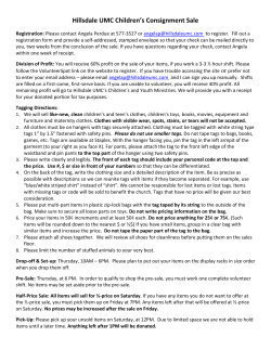


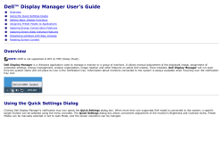


© Copyright 2026