
Things you didn't know Revit could do... or maybe AB2444
Things you didn't know Revit could do... or maybe
you just forgot
Paul F. Aubin
Paul F. Aubin Consulting Services
AB2444
Over the years using a program like Revit, you develop little tricks; tidbits of useful
information (like how View Range actually functions) and sometimes you are working on something else
and you remember a little gem you had forgotten (like how useful a view list schedule can be). While we
won't be rivaling Lynn Allen's 90 tips in 90 minutes (how does she do that?) we will cover quite a bit of
ground. Here's a short list: Linework tool, when to create Line Styles, what objects show above the cut,
what objects show below the bottom, how to create a Family Types parameter, line based Families for
fire tape lines, Decals, Filters and Browser Organization. And that's just the stuff you can do in any
release. New in this release: the new adaptive divide and repeat, View Templates, custom View Types
and exporting Material libraries. Anyone count that? Still not 90? Oh well. I still guarantee that there's
something for everyone here. If you use Revit, I have a tip for you.
Learning Objectives
At the end of this class, you will be able to:
•
Get your floor plan views under control with view range
•
Tame your unruly Browser by creating custom organization
•
Control nested Families parametrically with the Family Types parameter
•
Put View Templates in control of your views and keep them that way
•
Easily share a library of materials between all your projects
About the Speaker
Paul F. Aubin is the author of many CAD and BIM book titles including the widely acclaimed:
The Aubin Academy Mastering Series: Revit Architecture, AutoCAD Architecture, AutoCAD
MEP and Revit MEP titles. Paul has also authored several video training courses for lynda.com
(www.lynda.com/paulaubin). Paul is an independent architectural consultant who travels
internationally providing Revit® Architecture and AutoCAD® Architecture implementation,
training, and support services. Paul’s involvement in the architectural profession spans over 20
years, with experience that includes design, production, CAD management, mentoring,
coaching and training. He is an active member of the Autodesk user community, and has been
a top-rated speaker at Autodesk University (Autodesk’s annual user convention) for many
years. Paul has also received high ratings at the Revit Technology Conference (RTC) in both
the US and Australia and he spoke at the inaugural Central States Revit Workshop this year.
His diverse experience in architectural firms, as a CAD manager, and as an educator gives his
writing and his classroom instruction a fresh and credible focus. Paul is an associate member
of the American Institute of Architects. He lives in Chicago with his wife and three children.
Contact me directly from the contact form at my website: www.paulaubin.com
Things you didn't know Revit could do... or maybe you just forgot
Introduction
This session explores many tips and tricks for use with the Revit software. Since my
background is architectural, most of the tips are presented architecturally, however, many are
generic in nature and could apply equally well to Revit MEP or Revit Structure. I have about 40
items in this handout. I will try to cover as many as I can in the live session, but some will be
omitted due to time constraints (we only have 90 minutes after all…) I have marked the items
that I intend to skip in the live session with *** before the heading.
Modeling Tips
The first several tips will focus on modeling techniques. Some are very specific, some more
general in nature.
Ceiling Soffit Tip
Let’s start with a simple one. Ceilings, Walls, Roofs and Floors share many similar
characteristics in their type properties. If you are creating soffit conditions in your project, you
can approach it a few ways. Often however, the best approach in Revit is the one that closely
emulates what will really be constructed. As such, the vertical portions of the soffit should
typically be modeled simply as walls. In fact, the default template includes a wall type for this
purpose. If you are working in the imperial default template, the wall type is called: Soffit - 1/2"
GWB & Metal Stud. The default drywall ceiling GWB on Mtl. Stud uses a similar structure.
Most Revit users have experienced the way that walls cleanup automatically with one another.
Well it turns out that all layered system families (walls, roofs, ceilings, floors) share the same
cleanup behavior. So if the function and material of a layer are the same, they will cleanup. And
of course, functions also determine join priority, so a function [1] layer has more priority that a
[2] and so on. So our goal with the ceiling is to ensure first that the layers we want to cleanup
occur in the correct physical location and therefore give the desired adjacencies and then we
can simply join the geometry (see Figure 1).
Figure 1—Sketch the ceiling relative the core of the soffit walls and then join geometry
2
Things you didn't know Revit could do... or maybe you just forgot
Go ahead and use automatic ceiling if you like, but you will need to edit the sketch after it is
created. Delete the lines adjacent to the soffit walls and recreate them using the Pick Walls tool
with the “Extend into wall (to core)” option selected on the Options Bar. Finish the sketch. This
will make sure that the stud of the ceiling stops at the edge of the stud of the soffit allowing the
drywall to meet. On the Modify tab, use Join Geometry to finish the soffit in a section view.
Chase Examples
I have this one listed under modeling, but really it also qualifies as graphics or even data. I was
once asked by a client the “best” way to do chases and other void areas in plan. After a lengthy
discussion a file immerged with several possible approaches. All have their pluses and minuses.
Which is “better”, well I will leave that to you to decide, but I tend to favor approaches that are
simple to reproduce in any situation and yet closely resemble how they will actually be built.
This means that I tend to prefer items 1, 4, 5 and 7 in Figure 2. There are really two main issues
at work here: what is the desired graphical display of the condition and how do we intend to
document it (the wall tags in this case).
Figure 2—Several possible approaches to creating chases
Let’s take a quick summary of the file. This file is named: Chases_2013.rvt and will be made
available with the other downloadable materials for this class. Item 1 simply draws the condition
3
Things you didn't know Revit could do... or maybe you just forgot
using walls. It is simply and straightforward. The client however wanted the graphical display to
appear more like you see in item 2. To achieve item 2, the same walls were used, but the
Linework tool was employed to hide the edges in the upper cavity and lighten the edges in the
lower chase. (The Linework tool is discussed in more detail below).
Item three uses a feature built into Architectural Columns. They automatically merge with
adjacent walls. You can also see similar examples in items 8 and 10. The differences between
them is simply how the Architectural Column is built. In item 3, the column uses type parameters
which means that a new type has to be created for each unique condition. In item 8, the column
is instance-based, so that grips can be used instead to make each unique size. Item 10 also
uses instance parameters but has a custom L-Shape as well. (Items 3 and 8 use two columns
overlapping to form the L-Shape). The “X” in the chase for item 3 and 8 is a Shaft Opening.
Shaft Openings cut floors, ceilings and roofs, but not walls. So they would not help us in crafting
the model, but they do have integral symbolic lines which made it easy to create the “X”.
Items 4 and 5 are copies of item 1 again with a simple masking region used to cover over the
wall edges and give the solid appearance in item 5 or the lighter lines in item 4. This is quick
and easy, but masking regions are view specific. So you would have to manually copy and
paste them to other views and keep them up to date as the model changes.
Most of the other versions are simply variations of the ideas already discussed. Item 9 uses a
generic model family and join geometry. Item 11 does the same with an in-place family.
So as you can see, there are many approaches. For me personally, I tend to prefer to build the
geometry with walls (and some architectural columns). I then tweak the graphics with the
linework tool or in some cases a masking region, but I prefer linework wherever possible.
Unusual Roof Slopes
I recently worked with a client who had a roof that sloped in two non-orthogonal directions. In
other words, the roof was a flat plane, but the slope was not parallel to any of the roof edges.
The client knew the Z heights of certain key reference points on the roof as part of the design.
The solution became a combination of shape editing tools and a roof opening (void). The void
technique has been used in Revit for some time, but I had forgotten about it. While I was
working with this client, trying to help him solve his roof, I remembered this technique almost out
of the blue. Seemed very appropriate to therefore show it in this class (under the category
“maybe you just forgot…”).
The main challenge that the client had was that he knew three of the four points. I suppose if
either of us had wanted to get involved in complex mathematical calculations, we could have
figured out the fourth point. If it was not exact, the roof canted out of plane (very expensive) so
this this not what the client wanted.
4
Things you didn't know Revit could do... or maybe you just forgot
Figure 3—Creating a roof using shape editing and roof openings while maintaining a flat slab
After some deliberation, it dawned on me that the geometry of triangles says that we could
interpolate the fourth point if we made the roof a parallelogram. Then remembering the old Revit
trick for creating non-standard roofs before we had shape editing, we simply created a roof
opening void to subtract away the part we didn’t need (see Figure 3). I am only showing a single
slice here in the figure, but the building form was an octagon, so we went on to array the roofs
around to form the full building roof.
EQ dims anchor point
Here is a simple tip. When you use an equality dimension, you are actually applying a
constraint. So if you later move one of the items in the equality group, they will all move in order
to maintain the equality. All that is accept one of them. By default, Revit simply keeps one of the
elements next to the one you are moving fixed as you modify. But this is not always the way that
you want it to behave. The trick is to look for the small anchor symbol. You can drag this to any
of the elements in the equality group. Revit will then remember this location from now on and
when you move any of the items in the group, the one with the anchor will maintain its position
as the other move to stay equally spaced (see Figure 4).
5
Things you didn't know Revit could do... or maybe you just forgot
Figure 4—Use the anchor icon to determine which item in the equality group remains stationary
New Dimension Features
Dimensions have received a few handy enhancements. Sometimes you have a running string of
dimensions and later need to break the string into two separate strings. Doing so in releases
prior to 2013 would require either recreating the entire dimension string or using the Edit
Witness Lines tool to remove several of the witness lines and then create a new dimension for
other portion. Now you can remove a portion of a dimension line by using the TAB key to
highlight it and then press the DELETE key (see Figure 5).
Figure 5—We can now remove dimension segments
6
Things you didn't know Revit could do... or maybe you just forgot
In addition to this, you can now dimension the diameter of a circle and customize the display of
an equality dimension string to show a formula. For example, instead of displaying EQ on each
dimension, you could make a formula that displays the quantity of items and spacing such as 5
@ 4'-0".
Excluding Group members
Groups are collections of model elements (they can include both system and component/loadable
Families) that are treated as a single unit and given a name. The names of all your Groups show on the
Project Browser. You can use Groups to manage any repetitive portions of your project like typical
furniture layouts, typical toilet room layouts or even complete apartment or room configurations in hotels,
dormitories or apartment buildings. While effective in all these situations, there are times when duplicate
Groups will cause redundancies in the model, such as mirroring one apartment or hotel room layout next
to another. To solve such a redundancy (in the shared Wall in this case), use the Exclude from Group
feature.
Figure 6—Mirror a copy of the Guest Room Group
When you click the mirror Wall, a copy of the Group will appear, and a Warning dialog will also appear at
the bottom right corner of the screen. This warning is not serious and can be ignored. It is still a good idea
the read the warning message as most of the time there is some useful information conveyed in them.
The right side of Figure 6 shows the following warning message:
“Highlighted walls overlap. One of them may be ignored when
Revit finds room boundaries. Use Cut Geometry to embed one
wall within the other or tab-select one of the grouped overlapping
walls and exclude it from the group instance.”
In addition to potentially having an adverse effect on Rooms, you can also see that the overlapping Walls
do not cleanup very nicely and material counts in schedules would be inaccurate. The solution to the
7
Things you didn't know Revit could do... or maybe you just forgot
problem is simple: any element in any Group can be excluded from an individual instance of the Group. In
this situation, we can exclude the Wall from one of the Groups. To do this, place your mouse over the
double Wall. (The Group will pre-highlight). Press the TAB key. (Notice that the other Group now prehighlights). Press the TAB key again. This time, the Wall within one of the Groups pre-highlights. Click to
select this Wall. Click the Group Member icon to exclude this Wall from the Group (see Figure 7).
Figure 7—Tab into the Group, select the Wall and then click the icon to exclude it
Notice that the extra Wall has been removed and the cleanup is now correct. It is important to
realize that this change is not simply graphical override—Revit has actually removed one
instance of one of the Walls. For example, were we to have counted the Walls before started
and then re-count them now, there would be one Wall fewer in our model. Try it if you like.
Create a schedule that counts the element you wish to exclude (Walls in this case) before
performing the above procedure. Then check the schedule after the exclusion is complete. You
will have one less Wall on the schedule. You can also simply move the Groups apart from one
another to see that one is missing its Wall.
Cutaway 3D views
Getting just the right view of your model can sometimes be a challenge. One of my favorite ways to view
the model is with a 3D sectional cutaway view. You can create one a few ways. The fastest and easiest
way is to use the “Orient to View” option.
Suppose you have a tight area of a plan and to understand it better and make sure that there are no
conflicts or clashes, you want to get a better look. Start by cutting a section through the area. If the
section view tells you what you need to know, you can stop there. However, sometimes, even a section
“hides” key details and issues. A 3D view might be just the thing. However, if you have ever tried to
manually crop a 3D view to a smaller area, you know that this can be challenging. This is where the
Orient to View command comes in.
If you haven’t already cut a section, do so before continuing (it is a good idea to rename it as well). Next,
create a new {3D} view and then rename it. Make sure the 3D view is the active window (just click in it).
Right-click the ViewCube (see Figure 8), choose Orient to View > Sections > Section:Your Section
Name (where Your Section Name is the name you renamed your section view to).
8
Things you didn't know Revit could do... or maybe you just forgot
Figure 8—Right-click the ViewCube to orient a 3D view to any plan, section or elevation
The 3D view will match the section exactly. You can then spin the model to any angle you wish
using normal 3D navigating tools like the ViewCube or just hold your SHIFT key down and drag
with your wheel on the mouse. If you want to hide the crop box, select it and then on the ribbon
(on the View Graphics panel), click the Hide button and choose Elements.
Array Copying Tip
Have you ever created an array and then copied it somewhere else only to find that the array no
longer functions as an array? Sure you have the elements, they are group instances and look
like they should behave as an array, but the associated array dimension is nowhere to be found.
The trick to successfully copying an array and making sure that it remains parametric is to be
sure you select ALL of the array elements AND the array dimension before you copy or mirror. If
you do this, the newly copied array should function just fine (see Figure 9).
9
Things you didn't know Revit could do... or maybe you just forgot
Figure 9—Especially with polar arrays, the array dimension must be copied with the arrayed items
Data Tips
The next few tips focus a bit more on the data side than the model.
Use a Schedule to Edit the Model
Most projects need a schedule or two. Perhaps a doors schedule or an equipment schedule.
Revit schedules do a nice job of quickly generating the reports and schedules that are required
by our project documentation. But since a schedule is just another type of live view of the
project, it also makes an excellent way to make selections and perform edits in the model. The
trick here is to have two windows open at one. Open the schedule view and some other
graphical view for editing. This can be a plan, elevation or even a 3D view. The reason for this is
that while you can select multiple elements in the schedule, you cannot edit multiple selected
items in the schedule. So the minute you try to edit, it will change the selection to just the item
you are editing. To overcome this, try the following:
First, click and drag in one motion through several items in the schedule. They will all highlight
in both the schedule and in the other view you have open. Without deselecting, click once in the
graphical view to change the active view. If you do it correctly, the items selected in the
schedule will still be selected and the Properties palette will change to the items you have
selected. You can now edit the properties on the palette. When you apply the change, the
schedule will also update to reflect the new values (see Figure 10).
10
Things you didn't know Revit could do... or maybe you just forgot
Figure 10—Use the schedule to select multiple items and then shift focus to a graphical view to edit the
properties
Create a Custom Schedule Property
I am teaching a lab this year titled: Autodesk® Revit® Families: Step-by-Step Advanced
Concepts. In that session, one of the topics I will be discussing is the use of Shared
Parameters. Shared Parameters are custom user created parameters that can be “shared” by
multiple families and projects. The benefit of a shared parameter is that it can appear in
schedules broadening the kind of information you can include in your reports. If you want to get
more complete details on the use creation of shared parameters, I encourage you to download
the course materials for the class mentioned above, or drop in and attend if you have the
opening in your schedule.
In this tip, let’s simply review the basic steps to create a shared project parameter. A project
parameter is a parameter that is available to all elements in a project file. It works well for data
type parameters like say an Asset number or Serial number parameter. To create one, you must
first have a shared parameter file. I will leave those details to the handout from the Autodesk®
Revit® Families: Step-by-Step Advanced Concepts class. Look at the first several topics in that
paper. Once you have a shared parameter file, go to the Manage tab and click the Project
Parameters button. In the dialog that appears, click the Add button. In the “Project Parameters”
dialog, choose the Shared parameter radio button and then click the Select button. Choose the
parameter that you want from those available in the shared parameter file. Decide if the
parameter should be type or instance and on the right assign it to at least one category. You
can choose more than one if you like. Click OK to dismiss all dialogs (see Figure 11).
11
Things you didn't know Revit could do... or maybe you just forgot
Figure 11—Create a Project parameter from a shared parameter and assign it to one or more categories
You can now at this parameter to a schedule. It will also appear on the Properties palette for any item
belonging to the selected category or categories. There is much more you can do with shared
parameters. Be sure to take a look at that other course handout for more information.
View List Schedule
As your project grows in size, you will no doubt accumulate views very quickly. There are many
techniques you can employ to keep your project and its views organized. Some of these are
discussed below. In this tip, we will look at an easy way to quickly check the settings of many
views at the same time: use a View List schedule. A View List is simply a schedule of all the
views in your project and it is a great way to ensure that all the views have the correct settings.
Figure 12—Use a View List schedule to check the settings of all the views in your project
On the View tab, click the Schedule drop-down button and choose View List. Add your desired
fields. Add any sorting or grouping just like other schedules (see Figure 12). The nice thing
about a View List schedule is that in all ways it is a typical schedule. This means that you can
sort it, group it and most importantly edit it directly. So if you discover something set incorrectly
on one of your views, you can fix it right in the schedule.
12
Things you didn't know Revit could do... or maybe you just forgot
Organizational Tips
The next batch of tips involve organization and configuration of your project. We will discuss
ways to manage multiple views, make your project browser more manageable and to control
settings globally.
Scope Box
If you have a lot of datum elements and/or views in your project, it can be time consuming to get
them all sized and configured properly. The more complex the project, the more time consuming
this task can become. A Scope Box is an element that can be used to establish the extents of
one or more views, levels, grids and/or reference planes. Simply draw the scope box to the size
you want and then assign it to the datum element(s) and/or views (see Figure 13).
Figure 13—A scope box can be used to set the extents of views, grids, levels and reference planes
You can leave the scope box permanently assigned to the elements, or use it to establish the
desired extents and then remove it. I do this a lot when I want to have my plans all have the
same extents or to have a plan, elevation and section all match the same extents. You create a
Scope Box, assign it to the views. Then you remove it by either deleting the Scope box or
setting the views back to None. Either way, the view’s crop regions will remain the size of the
previous scope box, but will now be able to be adjusted. This technique can help speed up
project setup even if you do not intend to leave the Scope box permanent.
Associated Datum for Elevation Views
This technique is similar to the Scope box tip in that when you use this feature, it will adjust the
views in question. The difference is that this setting moves the cut line of your elevations or
sections and makes them align with a datum element such as a grid or reference plane. The
best use case for this is it provides a good way to synchronize the location of the cut line for
more than one elevation or section if so desired. You can use either girds or reference planes.
But I think reference planes are a little better as their placement is more flexible (not being tied
to the building’s columns for example). To use reference planes, be sure to name them on the
properties palette first. You then edit the properties of the elevation or section view and choose
the named reference plane from the Associated Datum property (see Figure 14).
13
Things you didn't know Revit could do... or maybe you just forgot
Figure 14—Assign an associated datum to an elevation or section to establish the location of its cut plane
Creating Custom Browser Organization
Views are the heart of any Revit project. However it won’t take long in even a small project for the
quantity of views to become unwieldy. The Browser Organization feature allows some relief. Both the
Views and Sheets branches of the project browser have editable parameters. Let’s take a look.
Several default browser organization types are provided in the out-of-the-box templates. You can use
these if they suit your needs or create your own. The same is true for the Sheets node. For example, in
the out-of-the-box imperial template, you can organize views by drawing type, discipline or phase. You
can even filter out those views that are already placed on sheets to help you identify the ones that still
need to be placed on a sheet. Sheets can be organized by date or the individual who drew them.
To apply one of these Browser Organization types, click on the Views or Sheets branches on the Project
Browser. On the Properties palette, choose the organization you want. You can edit existing types by
right-clicking on the Views or Sheets branches of the Project Browser and choosing Type Properties.
However, the default Type named “All” cannot be modified.
Tip: the default Organization Type named “All” is grouped by Family and Type on the Folders tab. The
Sort by setting is configured to View Name. This means that views will sort alphabetically regardless of
Level. So your “Site” view which should be first, will appear after “Second Floor” and so on. To remedy
this, create a new Browser Organization and change the Sort by to Associated Level (see Figure 15).
Figure 15—Both Views and Sheets can be edited. Edit either the groupings (Folders) and what is
included/excluded (Filters)
14
Things you didn't know Revit could do... or maybe you just forgot
Custom Browser Sort Parameters
Want to gain even more control over your Browser Organization? You can add custom Project
Parameters to the Views in your project and then build a Browser Organization to sort on these custom
fields. On the Manage tab, click the Project Parameters button (same as we did in the “Create a Custom
Schedule Property” topic above). Click the Add button to add a parameter. It can be a Project or Shared
parameter for this example. It is up to you. Name the parameter and from the Categories list, check the
Views checkbox. Click OK. Return to Browser Organization and your new field will be available to group
by on the Folders tab (see Figure 16).
Figure 16—Add a custom field to Views and then create a Browser Organization to group by it
Most firms have a well-established sheet numbering system. Usually such a system involves a
numeric code that designates the type of drawing (like “1” for plan and “2” for section, etc). In
such a scenario, and with many projects having dozens or hundreds of sheets, it can be useful
to organize the set by the sheet prefix (or any other useful criteria). To do this, return to Browser
Organization and then click the Sheets tab. Create or edit a Type and then you can edit either
the “Folders” which are the overall groupings shown in the browser tree or the “Filters” which
you can use to include or exclude sheets (or views) that meet your designated criteria. To sort
and group by sheet prefix, edit Folders and then choose to Group by Sheet Number. Next
choose the “Leading Characters” option and set the desired number of characters. For example,
two characters can be used to group the sheets so we end up with an “A1” series, then “A2” and
so on.
Create Custom View Types
For most view types; elevations, sections etc, you can create custom types. New in 2013, this
functionality is also available to plan views. A custom view type will have a unique (and typically
descriptive) name, settings to control the type of symbols it uses for callouts and also new in
2013 it can have a View Template assigned to it. We will discuss View Templates in the next tip.
What is significant about the custom view types is that they allow you to establish your office
standards for the way you want certain views to be created before the view exists. For example,
we could create a typical “Construction Plan” view type that has the furniture category hidden
and a “Furniture Plan” view type that shows the furniture. If you want to then create a new
15
Things you didn't know Revit could do... or maybe you just forgot
furniture plan for an upper floor of the building, you simply choose the appropriate view type and
it will be created with the correct settings. Furthermore, custom view types automatically make
their own categories on the Project Browser, so they present an alternative to the previous tip by
potentially eliminating the need for the custom parameter (see Figure 17).
Figure 17—Custom view types show as separate branches in the Project Browser and can automatically
assign a View Template to new views
Put View Templates in Control of Your Views
View Templates have been around for quite a while. Their core functionality: to save a collection
of view settings and allow a one click way to apply them to other views, remains the same in this
release. However a significant new feature has been introduced. We can now assign a View
Template to a view’s properties on the Properties palette. This puts the View Template in control
of the settings for that view. This gives us a central way to control office standards. If you
change the settings in the View Template, those changes are immediately updated in all
associated views. This is a hugely significant new feature in the 2013 release (see Figure 18).
Figure 18—View Templates can be assigned to the properties of a view putting them in charge of the view’s
settings
When you combine this new feature with the previous tip, you get a very powerful way to ensure
consistent standards across your project for each kind of view you need to maintain. For
16
Things you didn't know Revit could do... or maybe you just forgot
example, not only can you have different types of plans like a construction plan and furniture
plane noted above, but if the settings of either of these plans needs to be modified, you simply
edit the associated View Template and all of the views will automatically update.
It should be noted that when a View Template controls the properties of a view, the properties
can only be edited in the View Template. They will be greyed out in the view itself. To edit them,
go to the View tab, click the View Template drop-down button and choose Manage View
Templates (see Figure 19).
Figure 19—Individual views will have settings controlled by the view template greyed out
“Locking” a Workset
Sometimes on a team project, you have information that you would like to prevent from being
edited. For example, perhaps the column grid has been established and you do not want allow
anyone to edit it. Revit does not offer any sort of “lock” tool, but if your project is using
worksharing, we can achieve and similar effect by creating an “Admin” user.
To do this, from the Application menu, choose Options and then change the user name to
“Admin” or something similar. Make sure the items you want to “lock” are on a workset
dedicated to this purpose. In the example above, if you want to lock the column grid, you can
simply check out the Shared Levels and Grids workset. Otherwise, you can create a custom
workset, place elements on it and then “lock” it. To lock a workset, simply open the “Worksets”
dialog, select the workset you want to lock and click the Editable button. The name Admin will
appear in the Owner column (see Figure 20).
17
Things you didn't know Revit could do... or maybe you just forgot
Figure 20—To “lock” a Workset, create an Admin user and leave it checked out
Click OK to dismiss the dialog and then close the project file. When you synchronize, do not
relinquish User-created Worksets. This means that the user “Admin” will continue to own the
workset even after quitting Revit. No one else will be able to modify the Shared Levels and
Grids (or other workset locked this way) until Admin returns to the file and relinquishes.
Important: This tip goes directly against what is normally considered best practice. Typically,
we do not want anyone to close out of the project without first relinquishing. But in this case we
make an exception since our goal is the locking of a particular workset. Just remember to use
this technique with care and caution.
Share Materials Libraries
An exciting new feature in Revit 2013 is the introduction of material libraries. A material library is
a file that can contain one or more material definitions. Material libraries are external files (with a
.ADSKLIB extension) and are available in the “Material Browser”. Since they appear directly in
the browser from these external files, you can create a library of materials and then access
those materials from any project or family file without transferring project standards or using
copy and paste. This ensures more consistency and simplifies the process of sharing materials
between files.
To access or create a library, from the Manage tab, click the Materials button. At the bottom of
the “Material Browser” libraries will be listed on the left. Select a library from the list and its
contents will show on the right. A small gear icon reveals a menu to open or create new
libraries. As you create and modify materials in the browser, you can drag and drop them to a
library and vice versa. To share the library with an outside party, simply send them the
ADSKLIB file (see Figure 21).
18
Things you didn't know Revit could do... or maybe you just forgot
Figure 21—Create or open a library and drag and drop materials to and from it
Graphics Tips
Graphical display is an important part of any project. Most firms have graphical standards to
which they adhere. There are many tools to assist us in achieving the graphical display we
desire in Revit. In the next several tips we will look at various graphical techniques.
Grid Lines Custom Type Settings
I only just discovered this one recently so I thought I would share. If you edit the type properties
of the column grid, you will find a Center Segment option. Here you can choose between
Continuous (the default), None and Custom. Continuous uses the same line style throughout.
None removes the middle portion of the grid line, but still maintains the grid as a single grid line.
Custom allows you to set different line styles for the center and end segments. When you have
lots of grids in a large project, the drawing can get busy. The None option can be a good way to
remove some of the visual clutter to help clean up the drawings (see Figure 22).
Figure 22—Grid can be continuous or have a customized center segment
19
Things you didn't know Revit could do... or maybe you just forgot
Using the Linework Tool
The Linework tool allows you to override the graphics in a view edge by edge. Unlike other view
specific modifications, the linework tool customizes the individual lines and edges of the element
rather than the entire object. To use the linework tool, click the button on the Modify tab, choose
a line style from the Type Selector and then click on the edges on screen that you wish to
override. Each time you click an edge, the new linework will be applied to the edge and it will
remain selected with editable handles at each end of the line. You can stretch these handles to
confine the effect of the edit to a portion of the edge. To reset such an edit, repeat the process
choosing <By Category> as the line style.
View Range
The View Range is a horizontal range used to determine the graphics generated in a floor or ceiling plan.
The primary View Range is defined by a top plane, bottom plane and cut plane. Elements in Revit can be
either cutable or not. To determine which are cutable, look in the Object Styles (see Figure 23).
Figure 23—Non-cutable elements are blocked out in gray
Items that are cutable and intersect the cut plane, will display as indicated in the Cut column of Object
Styles (or by any Visibility/Graphics overrides assigned to the view). Items within the primary View Range
that are not cutable or occur below the Cut Plane will appear as indicated for Projection in Object Styles.
Casework, Windows and Generic Models will also appear in projection when they occur above the Cut
Plane but below the Top of the range.
View Depth is an additional range that can optionally be applied. By default, the View Depth coincides
with the bottom of the primary View Range. If extended below the bottom of the primary View Range,
items falling within this range will display using the pre-defined Revit Line Style named <Beyond> (see
Figure 24). Figure 24 was downloaded from a thread on the AUGI forums. To see the original image and
read a very informative thread regarding View Range, visit:
http://forums.augi.com/showthread.php?t=33237
20
Things you didn't know Revit could do... or maybe you just forgot
Figure 24—View Range explained (image courtesy of AUGI forums)
To experiment with this, try opening Line Styles (Manage tab, Settings drop-down button) and change the
color of the <Beyond> line style. Place an element within this range and view it in plan. It should appear in
the color you designated.
To edit the View Range, on the Properties palette, click the Edit button next to View Range. In the View
Range dialog, edit the height of any of the four listed planes. Each plane can be assigned a height
relative to one of the levels in your project. Offset values can be either positive or negative values relative
to the selected level. However, they must remain in order. In other words, Top has to be highest and View
Depth has to be lowest. Two or more values can be the same, then just cannot be out of order.
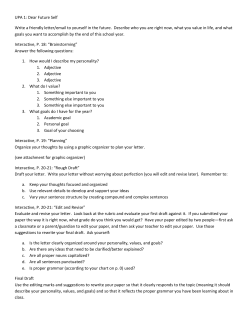
Figure 25 shows an illustration in elevation of the View Range of both Reflected Ceiling Plans and Floor
Plans with the corresponding plan views shown as well. Tags appear in both plan views showing the
“MH” – Mounting Height and “H” – Height of the elements displayed. Casework and Generic Models are
both cutable; Specialty Equipment is not. Note also that Casework and Generic Models that fall within the
region above the cut plane will appear in plan views using their projection settings. Ceiling Plans do not
use the Bottom of the View Range and the View Depth occurs above Top for ceiling plans, rather than
below Bottom as it does for Plans. In the figure, a single Specialty Equipment item appears in View Depth
range in Reflected Ceiling. The <Beyond> Line Style has been set to a dashed Line Style to illustrate this
condition in the RCP.
21
Things you didn't know Revit could do... or maybe you just forgot
Figure 25—Comparing Casework, Generic Models and Specialty Equipment with respect to Plan and
Reflected Ceiling Plan View Ranges
Hide at scales courser than
A handy setting is the “hide at scales courser than” setting. You can use this instruct sections
and elevations not to display below a certain scale. For example, you may want to create an
enlarged floor plan of a toilet room area. In that enlarged plan you create several interior
elevations or detail sections. When you return to the main overall floor plan, you likely will not
want the section and elevation symbols to display. This is easily accomplished with the “hide at
scales courser than” setting. To use this setting, simply go to the properties for the view in
question and choose the smallest scale where you want this elevation or section to display. For
22
Things you didn't know Revit could do... or maybe you just forgot
example, if the enlarged plan is 1/2"=1'-0", choose this same scale to prevent the section and
elevation symbols from showing at ¼" or 1/8" scales (see Figure 26).
Figure 26—Use the Hide at scales courser than setting to automatically hide large scale callouts in overall
scale plans
Temporary Dimension Display Settings
It is sometimes difficult to read the text of the temporary dimensions onscreen. And zooming
doesn’t help. There is a setting in Options that will enlarge the text globally throughout Revit.
From the Application menu, choose Options and then click on the Graphics tab. In the
Temporary Dimension Text Appearance area at the bottom, choose the font size you prefer.
The default is 8, I like 16.
Importing CAD files Lineweights
If you use CAD files in your Revit projects, you will get the best results from them if you are
familiar with how the CAD file is set up. Lineweights are a huge part of the legibility and
graphical quality of a drawing. Revit is able to read lineweights from the CAD file directly.
Unfortunately, most CAD users do not use the lineweight property. Instead they rely on legacy
“color equals lineweight” strategies. If the CAD file you are trying to import has its lineweights
assigned by color, then you must first create a mapping table before importing the file (see
Figure 27).
23
Things you didn't know Revit could do... or maybe you just forgot
Figure 27—Use the Import Lineweight Settings dialog to map lineweights from CAD colors
Custom Elevation tag symbols
A few releases ago, Revit added the ability to customize the graphics used for elevation
symbols. However, the default template still uses the old symbol. Let’s look at the process
involved to customize the elevation symbol. Assuming that you want to implement such a
customization as your firm’s new standard, it would be best to open your standard RTE template
file and perform this process there.
I posted some documents detailing the process on how to both build a custom elevation symbol
and load it on my public box account some time ago. I will make those files available with the
materials for this class including a sample RFA file. So if you want to try your hand at creating
your own custom symbol, you can review the steps in those documents. Here I will limit the
steps to just loading and assigning the custom symbol.
As noted already, start by opening your preferred office template file. Acquire or build a custom
family for the elevation symbol. (The family is actually two families: one for the arrows and one
for the symbol body. The arrows get nested into the symbol body family). If you do not have a
family, I have provided one based on the US National CAD Standard for your use.
On the Manage tab, click the Additional Settings drop-down and choose Elevation Tags. In the
“Type Properties” dialog that appears click the Duplicate button and type in a name. For the
Elevation Mark parameter choose the family you loaded (NCS Elevation Tag in this example).
Next, select one or more of your elevation symbols onscreen. On the Properties palette, click
the Edit Type button and then duplicate again. Change the Elevation Tag for your new type to
the one you just created. You can change the Callout Tag as well if you wish. The type that we
created here is actually a new elevation view type. so like we discussed in the “Create Custom
View Types” topic above, we can optionally choose to apply a View Template automatically as
well. When you click OK, the new elevation symbol will be applied to any elevations that you
had selected onscreen (see Figure 28).
24
Things you didn't know Revit could do... or maybe you just forgot
Figure 28—Create custom elevation tags and elevation view types to use in your template projects
Decals
Decals are a useful way to incorporate image files into your model. Like a real life decal, a Revit
decal gets applied to the surface of your 3D geometry. They are a good way to help visualize
artwork, signage, TV and movie screens, or even create details like arches and tile patterns. To
create a decal, start on the Insert tab. From the Decal drop-down, choose Decal Types. Create
a new decal using the icons in the bottom left. On the right browse to an image file for the decal.
Any PNG, TIF or BMP can be used. If you simply want to display the image like a painting on
the wall, accept all the remaining defaults (see Figure 29)
Figure 29—Create decals and apply them to surfaces in your model. Use Realistic visual style to preview
25
Things you didn't know Revit could do... or maybe you just forgot
To simulate a TV screen or other lighted sign, you can use the Luminance value. You can use
Brightness and Transparency for other special effects like a stained glass window for example.
To see the decal, you either need to use Realistic display visual style or perform a rendering.
Content tips
Content is a very important part of our work with Revit. As you might imagine, we could fill an
entire handout on tips related to content. In this section, I would like to share a few items that
are either favorites of mine, or just items that I am currently working on.
Line-based Families for Fire Tape lines
Some time ago, I received a question about creating complex linetypes (like those found in
AutoCAD where a letter(s) or other symbol appears alone the line as it is drawn. Alas, Revit
does not provide this ability for Line Patterns. You can create and edit your own Line Patterns
(Manage tab, Additional Settings drop-down, Line Patterns) and then apply them to elements in
Object Styles or Line Styles, but custom Line Patterns can only have a sequence of dashes,
dots and spaces. To work around this problem, you can create “Line-based” families. In
preparation for this class, I created two such families: one using the Generic Model line
based.rft family template and the other using the Detail Component line based.rft Family
Template. The first template creates a Model Family (or Model Line) and the other creates a
Detail Family (or Detail Line). Both achieve the desired result, so the choice of template is
dependent on your specific needs for the family. You can use such a family for all sorts of
needs. For example, to create Gas lines, Fence lines and other utility lines. Or even to add
symbols along the lines like the lines used to represent fire-rated walls as specified in the US
National CAD Standard.
The “line based” family templates include a Reference Line with a Length parameter assigned to
it. This is what allows you to draw a line with this family later. Your task is to simply create a
parametric Array within the family along this line. You can array anything you like. In this
example, I use nested Annotation families. Add the item you wish to repeat along the line to the
family and snap it to the Reference Line. You can add a parameter to control the offset from the
endpoints if you wish. Run the Array command and create a 2-item Array to start. Using the
Align tool, align the first item to the start point of the line (or the Reference Plane of the offset if
using) and lock it. Repeat on the other end for the second item. Create a parameter for the
Array dimension (it will be an Integer parameter to control the quantity of items). To make the
quantity adjust as you drag the length of the line, use some simple formulas in the “Family
Types” dialog. In Figure 30, you can see that a parameter called Spacing is added. This
parameter is used in to determine the quantity of arrayed items in the parameter called Array
Formula.
26
Things you didn't know Revit could do... or maybe you just forgot
Figure 30—Divide the Length by the Spacing and add 1 to get the quantity of arrayed items along the line
To create a more complex example, consider the fire-rated and smoke barrier lines specified in
the US National CAD Standard. In the NCS, a diamond symbol is used to represent a fire-rated
wall and the letter “S” for a smoke barrier. A Generic Annotation symbol family is used to create
the symbols. Generic Annotation symbols maintain a consistent size relative to paper (sheet)
not model scale. Use the same procedures to array the symbol along the Line-based family’s
Reference Line as the previous example. Spacing is the only challenge in this example. Even
though Detail families are two-dimensional, they are not annotation families and are therefore
scaled in model units. You can pick your most commonly used scale for life safety plans for
determining the proper value for spacing. Create Types in your family for each fire and smoke
rating combination (see Figure 31).
Figure 31—Arrayed element can be a graphic symbol as well. Used in conjuction with Filters, a very
customized Life Safety Plan can be devised
27
Things you didn't know Revit could do... or maybe you just forgot
Control nested Families parametrically with the <Family Types> parameter
In the previous fire tape example, <Family Types> parameter was used to make switching
between symbols easier. A Family Type parameter allows you to swap out the family and type
used for an element in your family with others of the same kind. In this case, the fire/smoke
symbol is a Generic Annotation family. When adding the parameter, choose <Family Type>
from the Type of Parameter list. This will open a “Select Category” list. Choose Generic
Annotations (see the left side of Figure 32).
Figure 32—Use a <Family Types> parameter to swap out a different symbol parametrically
At this point, one major step must still be performed before the Family Type parameter will
function. Like other parameters, we have to assign it to something in the Family—or “Label” it.
Select the instance of your Generic Annotation Symbol onscreen, edit its properties and notice
the Label setting. Here, since your Family Type parameter is set to Generic Annotations, you
will be able to select the name you gave to your parameter (Rating Symbol in the figure) and
thereby assign it to this item.
You will now be able to create multiple types for this family and each one will be able to choose
a different version (type) for the Rating Symbol (see the far right side of Figure 32).
Spline Through Points
If you work in the massing environment, you have likely used spline through points. This tool
gives a handy way to create a spline that passes through a series of points that you can place
anywhere you need them. However, Revit does not ask us what order we want the spline to
pass through the points and tends to favor a serpentine path. To overcome this, it turns out you
can build your spline through points in stages (see Figure 33).
28
Things you didn't know Revit could do... or maybe you just forgot
Figure 33—To control the shape of spline through points, build in stages
Divide and Repeat
The massing environment has been under active development since the 2010 release and
continues to get new enhancements with each release. This release, we get the new Divide and
Repeat functionality. This feature allows one or more adaptive components to be repeated
along paths or surfaces. You can repeat single elements, or create repeating patterns by
repeating a selection of elements. The functionality is very powerful, but has some quirks. I’d
like to share a few tips for getting the most out of this tool.
The first thing to realize about divide and repeat is that it requires an adaptive component for the
repeater. If you are not familiar with adaptive components, they are an entire class in
themselves… The repeating adaptive component family can contain any geometry you like. The
most important issue when creating the component is its orientation. You will certainly want to
control the orientation of the component as it repeats along the path or surface. To control this,
you must use adaptive points. This may seem obvious given the adaptive component
requirement, but it is worth mentioning. Particularly since I have created several examples that
do not have any adaptive points. In such cases, you have to do a bit of trial and error to
understand the default orientation of the nested component. It is not at all obvious (see Figure
34).
29
Things you didn't know Revit could do... or maybe you just forgot
Figure 34—Results vary greatly depending on how the adaptive component is built and placed
The next hurdle is that when placing the adaptive components on the point of the path or
surface, you must make sure that the Place on Face Placement option is active on the ribbon. If
you use the Place on Work Plane option, you will not be able to use repeat (see Figure 35).
Figure 35—In order to use repeat, the adaptive component MUST be placed with “Place on Face” active
Finally, nodes are required to place the components properly for repeat. Nodes appear
automatically on divided paths, but they do not on divided surfaces. You have to click the small
dialog launcher icon on the Surface Representation panel of the ribbon and check on Nodes
(see Figure 36).
Figure 36—In order for repeat to work, components must be placed on Nodes. Nodes are not visible on
divided surfaces by default
Constraining curves in families
When building family content I find that one of the more challenging tasks is constraining curves
so that they flex as expected. In the traditional (non-massing) family editor I typically try to
constrain everything to reference planes. This includes curves. To make a curve flex properly,
you will typically need to constrain its endpoints and possibly the radius or the curve itself. The
30
Things you didn't know Revit could do... or maybe you just forgot
endpoints can be constrained to reference planes easily enough with the align tool, but to
constrain the curve itself, you will usually have to place the dimension directly on the curve;
breaking the “always dimension reference planes” rule of thumb.
Let’s look at a simple example. Consider the form on the left side of Figure 37. We want to be
able to flex the width and height and have the arc form continue to fit within this overall
rectangle. As noted, aligning and locking the endpoints of the arc to both horizontal and vertical
reference planes is the first step.
Figure 37—Place a dimension directly on the curve to make sure it flexes as expected
Making sure that the “bulge” of the arc flexes as required cannot be done with the align tool.
You snap the arc to the reference planes when you draw it, but not lock it. So to constrain this,
you could devise a formula based on the width (which is a chord of the arc) and the height to
determine the radius, but the center point for this arc is not fixed. So you would have to ensure
that you had additional reference planes and constraints to make sure that the radius and center
point flexed properly. However, a simple dimension is all that is really needed. The trick is to
make sure that you dimension the reference plane first, then highlight and click the arc. Label
this dimension with the same height parameter and then flex it. It should now flex predictably.
Revit Plugins
We could do an entire session on Revit plugins and possible two or three sessions. There is a
vast array of plugins and add-ins available on the market both free and not free. In recent
releases of Autodesk products, we even have the Autodesk exchange where vendors can
distribute their apps and plugins to users from directly within their Autodesk products. My goal in
this topic is simple. I wanted to show just a few plugins that I use on a regular basis that each
solve common Revit needs. Each is free.
Revit Family Tools
Despite our best efforts to the contrary we all know that sometimes we end up with variances to
the published office standards and procedures. When using shared parameters it is highly
recommended that you establish and maintain a single Shared Parameter file for your entire
organization. Not one per project, not one per office, but ONE for the entire organization; all
31
Things you didn't know Revit could do... or maybe you just forgot
offices; all projects. However, this is often tough to accomplish for a variety of reasons. So what
do you do if you already had one? Revit Family Tools to the rescue. This free tool distributed
by the CAD Technology Center has a few very useful features and among them is a tool to
merge the parameters from two Shared Parameter files into one file. It is highly recommended
that you download this tool:
http://www.cadtechnologycenter.com/ctc-products.html
So if you end up with content that references a different shared parameter file, this tool can help
you clean things up.
Custom Hatch Patterns
Revit ships with many patterns to get us started, but nearly everyone discovers the need to
expand their hatch pattern library at some point. Revit uses PAT files, so you can actually import
any hatch pattern you have lying around from CAD and use it directly in Revit. Should you find
that the hatch you need is not readily available, you can use a very handy little tool called Hatch
22 to bake your own. Hatch 22 is a free plugin that works in all current releases of Revit. It relies
on four custom line styles that you use to draw your pattern directly in a Revit drafting view.
Once drawn, simply run the tool and it will generate the required PAT file for you behind the
scenes. It is easy to install and use and just simply works. Check it out at:
http://mertens3d.com/tools/revit/2012/hatch22-2012/hatch22-2012.php
Figure 38—Hatch 22 uses four custom line styles to build a drafting view pattern. This is then converted to a
hatch PAT file
32
Things you didn't know Revit could do... or maybe you just forgot
Room and Door Renumbering
A very common wish list item is to have door numbers match the numbers of the room which
they serve. Surprisingly this functionality is not native to Revit. However, several third party
developers have stepped up to the task including CTC, IMAGINiT and D|C|CADD Company.
Not all of these are free, but some are. Some also do much more than renumber rooms and
doors, so do explore the full capabilities at each vendor’s website.
At the Autodesk Exchange
D|C|CADD Company:
http://apps.exchange.autodesk.com/RVT/2013/en/Detail/Index?id=appstore.exchange.autodesk
.com%3adctoolsforautodeskrevit%3aen
CTC:
http://apps.exchange.autodesk.com/RVT/2013/en/Detail/Index?id=appstore.exchange.autodesk
.com%3arevitrenumbering%3aen
Vendor Website
IMAGINiT: http://imaginit.com/software-solutions/imaginit-products/imaginit-utilities-for-revit
Partial Blog list
I would like to end not with a tip, but with a list of blogs that I visit regularly. You are encouraged
to add these to your blog feed is you have not already. Again this is not a comprehensive list.
My apologies if your own blog or your favorite blog did not make the list. Again, these are just
the ones that I find myself visiting several times a week. There are literally hundreds of blogs out
there devoted to Revit. So if you have not started your own list, then consider this your “starter
pack.”
Mine of course: http://paulaubin.com/category/blog/
Luke Johnson of Dimond Architects Pty Ltd: http://whatrevitwants.blogspot.com/
Steve Stafford of AEC Advantage: http://revitoped.blogspot.com/
David Light of Case, Inc. http://autodesk-revit.blogspot.com/
Zach Kron of Autodesk: http://buildz.blogspot.com/
Aaron Maller of The Beck Group: http://malleristicrevitation.blogspot.com/
The Revit Clinic (Autodesk): http://revitclinic.typepad.com/my_weblog/
Andy Milburn: http://grevity.blogspot.com/
Jeffrey Pinheiro (The Revit Kid)http://therevitkid.blogspot.com/
33
Things you didn't know Revit could do... or maybe you just forgot
David Baldacchino and Steve Campbell: http://do-u-revit.blogspot.com/
Rory Vance of KnowledgeSmart: http://the-knowledgesmart-blog.blogspot.com/
Please feel free to experiment further. Thank you for attending.
Further Study
You can find more information and tutorials in The Aubin Academy Master Series: Revit
Architecture.
I also have Revit video training available at:
www.lynda.com/trial/paubin. I have five courses at lynda.com:
Revit Essentials (2011 and 2013 editions), Revit Family Editor,
Revit Architecture Rendering and Advanced Modeling in
Revit Architecture.
If you have any questions about this session or Revit in general, you can use
the contact form at www.paulaubin.com to send me an email.
Thank you for attending. Please fill out your evaluation.
34


© Copyright 2026