
Building Twisted Pair Cables
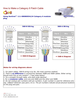
Building Twisted Pair Cables
Note: This is just one of many different styles and types of termination.
Introduction
Category 5e (CAT5e) twisted pair cable is becoming the mainstay for
today's data transfer needs. Twisted pair cable can transfer both voice and
data up to 100 Megabits per second (mbps) if installed correctly.
In this section you will learn how to terminate twisted pair cables that
maintain a Category 5e rating.
Objectives
At the end of this section, you should be able to:
•
List the tools required to assemble a twisted pair cable
•
Describe the assembly process
•
Identify the importance of maintaining the correct number of twists
•
Identify four items you should check before crimping the cable
•
Test cable segments for continuity
Twisted Pair Overview
In this section you will learn how to build and test a twisted pair cable for
use with Honeywell Security products.
Twisted pair cable is generally rated in four categories, with the difference
between them based primarily on performance:
•
•
•
•
Category 3 (CAT3)
Category 5 (CAT5)
Category 5e (CAT5e)
Category 6 (CAT6)
All four categories are the same gauge of wire with the same number of
pairs; however, the type of connector, twist ratio and quality of connection
determines whether or not the cable meets CAT5e specifications.
CAT3, CAT5, CAT5e and CAT6 all have a different twist ratio. The cable
can be de-rated with the type of connector and quality of controls.
Tools for Twisted Pair Cable Construction
The following basic tools are required to terminate twisted pair cable:
•
•
•
•
PVC Coating Stripper
4' Wire Strippers/Cutters
Continuity Tester
RJ45/RJ11 Crimp Tool
Other materials that we will be using:
•
•
•
CAT5e Twisted pair cable
CAT5e Inserts for panels and receptacles (Keystone jacks)
RJ45 Male connectors (Modular ends)
Installation Overview
It is important that the color-coded pairs are properly installed to maintain
the proper functioning of the cable. There are two standards that govern
the order of pairs, 568A and 568B. In this course, we will use the 568A
standard.
The cable segment you will build represents the cable that runs between a
Receptacle and a Panel.
The basic steps for building a CAT5e connection are:
•
•
•
•
•
•
•
•
Cut the cable to uniform length
Strip PVC coating back 3/4" (1.5 centimeters)
Carefully order the cable pairs
Insert into female connector
Visually inspect to ensure that the cable is inserted all the way into the
connector so that it will make a connection when seated
Press the connector lid to seat the wire
Re-inspect the cable
Step-by-step directions are provided below
Connecting CAT5e TP Modules
The following steps will guide you through the process of installing a
CAT5e Insert (Part # ML5N/R).
1. Strip back ¾ " to 1" of the outer PVC jacket of CAT5e Cable
2. Carefully arrange the individual conductors so they match the 568A
color schematic shown on the CAT5e inserts. Note: Do not unravel a
wire pair more than ½ inch. Doing so will cause the cable to drop
to CAT3 performance level.
3. Once your individual conductors are arranged, trim them with the wire
strippers/cutter to square off the end.
Green
White/Green
White/Orange
White/Blue
Blue
Orange
Brown
White/Brown
Figure 4-1: Cable Stripped and Pairs Aligned (see next page for new connections)
4. At the rear of each channel, you will notice a razor blade style post
which the conductors must seat into. These razor blade posts pierce
the PVC jacket of each conductor and make contact with the wire,
eliminating the need to strip back each individual conductor.
5. Insert the conductors into the channels on the CAT5e inserts, making
sure they are pushed in far enough to hold the conductors in place
while you insert the rest. (see figure 4-2)
A
B
2 1 3 5 4 6 8 7
Figure 4-2: Inserting conductors into the channels of the CAT5e Inserts (see next page for new connections)
Technical Support Step-By-Step
The picture below is the new connector with the color code on the connector.
6. Once you have inserted the conductors into the channels, install the
blue termination cap. The termination cap forces the conductors down
and insures that they make contact with the razor blade posts. Once
the termination cap has been installed the cable will stay in place.
Terminating an RJ45 Connector
The RJ45 connector is the male component of the cabling system. As with
the female connector, it is important that the individual pairs are not
unraveled more than ½" (approximately 1 centimeter), keeping the pair
twist as close to the termination point as possible.
This cable represents the patch cable you will need to connect PANEL
components and test cable segments.
The following is a step-by-step installation procedure:
1. Take a section of twisted pair cable
2. Trim the end of the cable using diagonal wire cutters
3. Strip off ¾” to 1" of the outer PVC jacket
4. Carefully align the pairs of wires to line up with the connector as
illustrated in Figure 4-4
1.White/Green
2.Green
3.White/Orange
4. Blue
5.White/Blue
6.Orange
7.White/Brown
8.Brown
Figure 4-4: 568A Standard
5. Cut off the excess beyond ½”
6. Insert the cable into the connector making sure the individual wires are
inserted all the way to the rear of the RJ45 connector and will make
contact with metal points on the RJ45 connector.
7. Inspect the wire and connector carefully. Make sure the pairs are
aligned properly inside the connector and inserted completely into the
connector.
Note: Once the connector is crimped, it cannot be removed.
8. Insert the RJ45 connector into the crimp tool and crimp the connection.
8.Brown
7.White/Brown
6.Orange
5.White/Blue
4. Blue
3.White/Orange
2.Green
1.White/Green
Figure 4-5: Completed RJ45 Connector
9. Check the connection again for any loose wires.
Testing for Continuity and Cross Wiring
To this point you have created a cable with RJ45 connectors to be used
for a patch cable and a cable segment equipped with full-duplex female
connectors that represent the connection between a receptacle outlet and
a panel.
Cable Testing Overview
There are two basic tests we will perform on the cable in this lab:
•
Continuity
•
Matching pairs
Continuity
When inserting the individual wires into the connector, especially a CAT5e
insert, a wire that is not fully seated will cause an interruption of the signal.
Matching Pairs
Transmission of data is not possible if the pairs are not in the correct order
(for example, not lined up according to the 568A color-code). When
inserting the wire into the RJ45 connectors, it is easy to mix up the order
of the wires or to get two wires into the same slot.
The following testing procedure will help you assess cables that have
problems.
Required materials
You will need the following materials to test cable:
•
A completed section of cable
•
Two patch cables
•
Continuity tester
Testing a Patch Cable
Follow these step-by-step instructions to test your cable segment:
1. Connect either end of your patch cable to the 568A port, as illustrated
in Figure 4-6. This connection tests for continuity and verifies that the
pairs are matched correctly.
2. If the cable is wired correctly, the Master tester will display each pair in
sequence
3. If the test failed, the lights will not flash in sequence and/or the
remote tester will indicate a fault.
US0C
568A
M A S TER
PAIR
568B
US0C
568A
568B
R EM O TE
NORMAL
REVERSE
Figure 4-6: Patch Cable Connected
Testing a Cable Segment
In this activity you will be testing the cable segment used between the
receptacle and panel. For this test, you will use two patch cables, the
cable segment and the continuity testers. (Testing an actual installation is
faster with two people.)
To test a cable segment attach the patch cables and cable segment to the
tester indicated in Figure 4-7.
Cable
Segment
Patch
Cable
US0C
568A
M A S TER
PAIR
568B
US0C
568A
568B
R EM O TE
NORMAL
REVERSE
Figure 4-7: Cable Segment and Patch Cables Connected to Test Equipment
All the tests should prove positive. If any do not, inspect the connectors on
the cable segment, correct the problem, and retest.
At this point, we have determined that the cable is not shorted and that all
pairs are aligned correctly.
Certification of CAT5e Cable
CAT5e cable performance can be hard to maintain if not installed
correctly. In some installations, you may be required to certify each cable
segment for CAT5e performance.
CAT5e certification is done using a sophisticated set of testing
instruments. For information on CAT5e Certification equipment, contact
your local distributor.
It is recommended to certify CAT5e and document the certification on
each CAT5e run.
Summary
This section has guided you through the installation and testing of CAT5e
twisted pair cable. The major problems with cable connections are listed
below:
•
Individual Pairs are untwisted more than ½”
•
Pairs are not ordered properly
•
Wires are not seated into connectors properly
•
Nicks on conductors during PVC stripping
There are facets to twisted pair cable that we have not covered, such as
performance testing and segment certification.
Cable certification is critical in larger installations. A savvy network
administrator or MIS director will require certification of each cable
segment in a commercial installation.
In the next section, you will learn how to build coaxial cable connections.


© Copyright 2026