
ME 352 System Dynamics and Control Lab #2 (comp) â Spring 2015
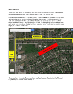
ME 352 System Dynamics and Control Lab #2 (comp) – Spring 2015 MODELING OF A VEHICLE SUSPENSION SYSTEM In this lab session, we will simulate vertical motion of a vehicle striking a bump. A simplified diagram of a suspension system consisting of spring and damper elements is shown below. You are expected to derive equations of motion for this system and obtain a transfer function between the road vertical position r (t ) and the resulting vertical position of the vehicle, x(t ) . Road profile resembling a bump is also shown below. Assume that the vehicle’s horizontal speed v is constant and equal to 10 m/s. The following parameters will be used k 10000 N/m m 950 kg H 0.1 m L 1 m Use a value within the range of 100–1000 Ns/m for the damping constant. Lab procedure [2 pts] 1. Write down equations governing the vertical motion of the suspension system. Find the transfer function between road vertical position r (t ) and vertical position of the vehicle, x(t ) . 2. Develop a Simulink model representing the road surface r (t ) . Make sure you consider the vehicle speed in defining road profile. Consider using two ramp signals and a step signal to construct the desired profile. Another alternative is to a Signal Builder block. After generating the correct signal for r (t ) , show it to lab assistant and claim your 1 pt. 1 3. Then, add transfer function representing the motion and obtain a simulated response for x(t ) . Try with different values for c and choose a value, which would result in maximum passenger comfort. Show your simulation result in return for your other 1 pt. Reporting [3 pts] Please prepare a short (max. 3 pages) report and submit within a week of the lab session. Individual lab reports are expected for this computational experiment. Write down equations leading to derivation of the transfer function. Show the blocks which generate reference signal and the complete block diagram. Within your report, the following sections should be included: Modeling section, present equations of the physical system. Block diagram of the system. Plots of reference input r (t ) , and output displacement x(t ) (on the same graph) for three different values of damping constant, c. Give a 1‐paragraph discussions part. 2


© Copyright 2026