
How to Guide Video Timing Measurements on WFM2200 WFM2200 Version 1.x.x Software
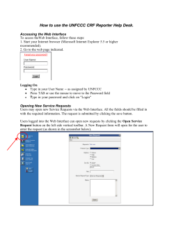
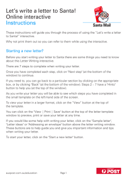
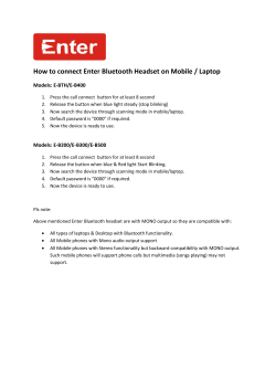
How to Guide Video Timing Measurements on WFM2200 WFM2200 Version 1.x.x Software How to Guide Video Timing Measurement Video Timing of equipment within a facility or on location is a critical part of synchronization. Ensuring correct timing of each piece of equipment means that sources can be easily switched and disturbance to the picture can be avoided. Each source on location or within the facility needs to be Genlocked using an analog Black Burst or Tri-Level Sync reference signal. How to Perform Timing Display Measurements on WFM2200. Figure 1 shows the input connections on the top of the WFM2200 in order to perform video timing measurements. The analog black burst or tri-level sync signal should be connected to the REF IN and the SDI input can be connected to either SDI A or SDI B. Note: Both the SDI (Serial Digital Interface) video and analog reference inputs are terminated within the instrument. Figure 1. WFM2200 Input Connections. How to Configure the Timing Measurement 1. Select the appropriate video input SDI A or B on the front panel of the instrument. 2. Press the EXT button on the front panel to enable the video timings to be derived from the external reference input. 3. The status bar at the bottom of the display will automatically show the video format of the SDI Input and Reference signal, if present. 4. Press and hold DISPLAY SELECT to toggle between Full and 4-Tile mode. Ensure that the display is in Full Screen mode. How to Guide Video Timing Measurement Note: If the instrument does not toggle between Full and 4-Tile mode and thumbnail picture is shown instead. The DISPLAY SELECT button is currently enabled for Thumbnail operation to change this configuration press the MAIN button and navigate to Display Select using the up or down arrow keys. Then press SEL button to toggle the operation from Thumb to Tile Sel. When in Tile Sel mode the DISPLAY SELECT button is used for tile navigation and toggling between Full and 4 Tile modes. 5. Press the MEAS button to select the Timing Display as shown in Figure 2. If the timing display is not shown then perform the following steps. 6. Push and hold the MEAS button to display the menu. 7. Use the up/down arrow keys or general knob to navigate to Display Type. 8. Press SEL to enter sub menu. 9. Use the up/down arrow keys or general knob to navigate to Timing Measure. 10. Press MEAS button to dismiss the menu Figure 2. WFM2200 Timing Display in Full Screen mode. How to Guide Video Timing Measurement How to Interpret the Timing Display When in External Reference mode the timing display provides direct readouts on the right hand side of the display for the vertical and horizontal offset between the analog reference signal and the SDI input as shown in Figure 3. The timing information is provided within the graphical display on the left hand side of the display. Black rectangle automatically resizes to represent complete video frame based on video input format. Advanced Horizontal Offset shown on left hand side. Delayed Horizontal Offset shown on right hand side. Advanced Vertical Offset shown on upper half of display. Delayed Vertical Offset shown on lower half of display. Green circle overlaid over white center crosshairs indicates no timing offset between video input and reference. White circle offset from white center crosshairs shows timing difference between video input and reference. Figure 3. Tektronix patented Timing Display. How to Guide Video Timing Measurement When a signal has a timing offset between the input and the reference the circle will be white and show the amount of timing offset. Figure 4 shows a timing offset in the measurement with direct readouts showing the amount of horizontal and vertical offset of the two signals. Timing adjustment should be performed to move the circle so that it is overlaid over the white crosshairs. Figure 4. Timing Display showing timing offset. Note: Timing measurements readouts are made relative to the input video format. Simply use the graphical display to adjust the horizontal and vertical timing adjustments of the device until the white circle turns green and is overlaid over the white crosshairs in the center of the display. How to Guide Video Timing Measurement Timing Display Saved Offset. In some case the user may wish to have a specific offset between the video input and reference and make timing measurement using this offset. This can be achieved by using the Saved Offset function within the timing measurement. With the specific offset applied between the video input and reference perform the following operations. 1. 2. 3. 4. 5. 6. Push and hold the MEAS button to display the menu as shown in Figure 5. Navigate using the up/down arrow keys to Save Offset. Press SEL button to save the offset between the video input and reference. Using the up/down arrow keys or general knob navigate to Relative To. Press SEL to enter sub menu and select Saved Offset as shown in Figure 5. The timing circle will now turn green and be at the center of the white crosshairs and the display indicates that the “Relative to:” is now using Saved Offset. Figure 5. Timing Display showing “Relative To:” menu selection. How to Guide Video Timing Measurement Timing Measurements Relative To: SMPTE has defined several methods for measuring the video timing between SDI inputs relative to an analog reference. The user can choose one of the following Relative To modes. Analog (DAC) setting uses the methodology illustrated in appendix B of SMPTE RP168. This method shows the SDI signal being converted to analog. The converted analog signal is then compared to the analog reference. For this mode the nominal delay of the D to A converter is assumed to be 4.6 microseconds for SD, 1.3us for HD and 0.0 us for 3Gb. The "0.0us" delay for 3Gb means the Analog (DAC) and Serial (0H) modes are equivalent for 3Gb signals. Serial (0H) setting uses the methodology implied in appendix A of SMPTE RP168. In this mode timing is considered to be zero when the "0H" sample of the serial stream aligns with the reference edge of the analog sync. Note that this timing is actually at the scrambled interface which is slightly different than timing to the parallel data into the serializer or the parallel data out of the deserializer due to delays in those functions. Saved Offset. In this mode, you can save the timing from one signal and then display the timing relative to that saved offset. Note: The resolution of the timing display for SD signals is one 27 MHz clock cycle or 37 ns. For HD signals, it is one clock at 74.25 MHz, which equates to about 13.5 ns. Troubleshooting Timing Problems The Status bar at the bottom of the display can be used to verify the input signals presence and format. When the EXT reference button is selected information is provided on the detected format of the analog reference signal whether black burst PAL or NTSC or HD tri-level sync. Typical timing measurements are made between similar video frame rates for the video input and reference. If video formats are mismatched this will be indicated within the status bar. The SDI video input can be verified by viewing the picture display or waveform displays of the signal to ensure that the signal is of the correct format and no disturbances or errors are present within the signal. The video session display can be used to verify the format and structure of the SDI signal. How to Guide 1. 2. 3. 4. 5. Video Timing Measurement Push and hold the STATUS button to display the menu as shown in Figure 6. Navigate using the up/down arrow keys or general knob to Display Type. Press SEL button to enter the sub menu. Using the up/down arrow keys or general knob and navigate to Video Session. Press STATUS to dismiss the menu. The video session display provides information on the input format along with SAV Place Err, Field Length Err, Line Length and CRC errors as shown in Figure 6. If this status information is shown in Green then there are no errors present in the signal format. If they are shown in red this indicates a current error with the signal and if they are shown in yellow this indicates an error had occurred previously in the signal. Figure 6. Video Session display. The user may also need to verify the level and integrity of the analog reference signal to ensure that the timing problems is not caused by noise present on the signal or due to interference from a faulty distribution amplifier. Within the Tektronix WFM2200 the user can view a waveform trace of the analog reference input. How to Guide Video Timing Measurement Viewing Analog External Reference. 1. 2. 3. 4. 5. Push and hold the WFM button to display the menu as shown in Figure 7. Navigate using the up/down arrow keys or general knob to Display Type. Press SEL button to enter the sub menu. Using the up/down arrow keys or general knob and navigate to Ref Waveform. Press WFM to dismiss the menu. Figure 7. External Reference waveform display. The user can view a waveform display in either line or field sweep of the analog reference signal whether black burst or tri-level sync. This can be used to verify the amplitude of the reference signal and whether noise or hum is present within the signal that could cause problems with a device locking to this reference signal. How to Guide Video Timing Measurement Timing of 24 frame video signals. For input and reference signals with closely related frame rates, there is only one timing relationship, so a single circle is shown on the display to indicate the timing of the input signal. When the video input and reference combinations have a more complex relationships, multiple circles are displayed to indicate all the possible interpretations of the timing offset. For example, if the input is 1080p at a field rate of 23.98 Hz, and the reference is NTSC at 59.94 Hz, then, although they are at different rates, the timing relationships between the signals will repeat once for every five fields of the input and five frames of the reference. This then allows for five possible ways to measure timing between these two signals. In this case, the timing display shows five circles representing the five possible timings and the one that is closest to zero will be shown with emphasis as shown in figure 8. Figure 8. NTSC External Reference with 24 frame video input. How to Guide Video Timing Measurement Note: If you have an input and reference combination that requires multiple timing indicator circles, then it can be misleading to compare timing offsets between multiple inputs. Since the timing display chooses the smallest of the possible timing offsets, if a large timing difference exists between two inputs then they may not be matched. This problem will also occur using traditional timing methods unless one uses something like the SMPTE318 10 field flag to identify a specific sub-multiple of the reference. References WFM2200 Waveform Monitor Data Sheets, Fact Sheets and additional product materials can be found at www.tektronix.com/ How to Guide Video Timing Measurement ASEAN / Australasia (65) 6356 3900 Austria 00800 2255 4835* Balkans, Israel, South Africa and other ISE Countries +41 52 675 3777 Belgium 00800 2255 4835* Brazil +55 (11) 3759 7627 Canada 1 800 833 9200 Central East Europe and the Baltics +41 52 675 3777 Central Europe & Greece +41 52 675 3777 Denmark +45 80 88 1401 Finland +41 52 675 3777 France 00800 2255 4835* Germany 00800 2255 4835* Hong Kong 400 820 5835 India 000 800 650 1835 Italy 00800 2255 4835* Japan 81 (3) 6714 3010 Luxembourg +41 52 675 3777 Mexico, Central/South America & Caribbean 52 (55) 56 04 50 90 Middle East, Asia, and North Africa +41 52 675 3777 The Netherlands 00800 2255 4835* Norway 800 16098 People’s Republic of China 400 820 5835 Poland +41 52 675 3777 Portugal 80 08 12370 Republic of Korea 001 800 8255 2835 Russia & CIS +7 (495) 7484900 South Africa +41 52 675 3777 Spain 00800 2255 4835* Sweden 00800 2255 4835* Switzerland 00800 2255 4835* Taiwan 886 (2) 2722 9622 United Kingdom & Ireland 00800 2255 4835* USA 1 800 833 9200 * European toll-free number. If not accessible, call: +41 52 675 3777 Updated 10 February 2011 For Further Information Tektronix maintains a comprehensive, constantly expanding collection of application notes, technical briefs and other resources to help engineers working on the cutting edge of technology. Please visit www.tektronix.com Copyright © 2012, Tektronix. All rights reserved. Tektronix products are covered by U.S. and foreign patents, issued and pending. Information in this publication supersedes that in all previously published material. Specification and price change privileges reserved. TEKTRONIX and TEK are registered trademarks of Tektronix, Inc. All other trade names referenced are the service marks, trademarks or registered trademarks of their respective companies. 2/12 2PW-27386-0


© Copyright 2026