
LSMS 9.0 Maintenance Manual
LSMS 9.0 Maintenance Manual
Table of Contents
List of Figures
List of Tables
Chapter 1. Introduction
Chapter 2. LSMS Overview
Chapter 3. Routine Procedures
Chapter 4. Preventive Maintenance
Chapter 5. Restarting Software Processes
Chapter 6. Managing Server Status
Chapter 7. Recovering from Site Failures
Chapter 8. Verifying Recovery
Appendix A. Commands
Appendix B. Automatic Monitoring of Events
Appendix C. Downloading Files from an NPAC to the LSMS
Appendix D. Worksheets
Appendix E. Query Server Maintenance Procedures
Index
910-4499-001 Rev A, October 2006
Table of Chapters
910-4499-001 Rev A, October 2006
Tekelec LSMS
Release 9.0
Maintenance Manual
910-4499-001 Revision A
October 2006
Copyright© 2005, 2006 Tekelec.
All Rights Reserved
Printed in U.S.A.
Notice
Information in this documentation is subject to change without notice. Unauthorized use or copying of this
documentation can result in civil or criminal penalties.
Any export of Tekelec products is subject to the export controls of the United States and the other countries where
Tekelec has operations.
No part of this documentation may be reproduced or transmitted in any form or by any means, electronic or
mechanical, including photocopying or recording, for any purpose without the express written permission of an
authorized representative of Tekelec.
Other product names used herein are for identification purposes only, and may be trademarks of their respective
companies.
Trademarks
The Tekelec logo, EAGLE, G-Flex, G-Port, IP7, IP7Edge, IP7 Secure Gateway, and TALI are registered trademarks
of Tekelec. TekServer is a trademark of Tekelec. All other trademarks are the property of their respective owners.
Patents
This product is covered by one or more of the following U.S. and foreign patents:
U.S. Patent Numbers:
5,008,929, 5,953,404, 6,167,129, 6,324,183, 6,327,350, 6,456,845, 6,606,379, 6,639,981, 6,647,113, 6,662,017,
6,735,441, 6,745,041, 6,765,990, 6,795,546, 6,819,932, 6,836,477, 6,839,423, 6,885,872, 6,901,262, 6,914,973,
6,940,866, 6,944,184, 6,954,526, 6,954,794, 6,959,076, 6,965,592, 6,967,956, 6,968,048, 6,970,542
Ordering Information
For additional copies of this document, contact your sales representative.
Table of Contents
Table of Contents
Chapter 1. Introduction
Overview ...................................................................................................................1-2
Scope and Audience ..................................................................................................1-2
What’s New in This Release .....................................................................................1-2
What’s New in This Manual .....................................................................................1-3
Compatibility .............................................................................................................1-4
Manual Organization .................................................................................................1-4
Related Publications ..................................................................................................1-5
Documentation Packaging and Updates ....................................................................1-7
Documentation Admonishments ...............................................................................1-7
Customer Care Center ...............................................................................................1-7
Emergency Response ..........................................................................................1-8
Using a System Maintenance Log .............................................................................1-8
List of Acronyms .....................................................................................................1-11
Chapter 2. LSMS Overview
Introduction ...............................................................................................................2-3
LSMS System Architecture .......................................................................................2-4
LSMS Connectivity ...................................................................................................2-5
LSMS Hardware Overview .......................................................................................2-6
T1100 Application Server ..................................................................................2-6
Network Attached Storage ..................................................................................2-6
DC LSMS Hardware Overview ........................................................................2-12
AC LSMS Hardware Overview ........................................................................2-17
LSMS Software Overview ......................................................................................2-19
Operating System Layer ...................................................................................2-19
Base Platform Software ....................................................................................2-20
Support/Base Utilities Components ..................................................................2-20
LSMS Applications ..........................................................................................2-22
Overview of High Availability ................................................................................2-26
Hardware Redundancies ...................................................................................2-26
Software Availability Design ...........................................................................2-28
Enhancing High Availability with a Shadow LSMS ..............................................2-29
Understanding the Surveillance Feature .................................................................2-29
910-4499-001 Rev A, October 2006
i
Table of Contents
Configuring a Customer-Provided Administration Console ............................ 2-31
Controlling the Surveillance Feature ............................................................... 2-31
Understanding Surveillance Notifications ....................................................... 2-33
Logging Surveillance Notifications ................................................................. 2-33
Understanding the Service Assurance Feature ....................................................... 2-33
Service Assurance Terminology ...................................................................... 2-35
Interface Implementation ................................................................................. 2-35
Number of Associations Per Service Assurance System ................................. 2-36
Notification Upon Loss of Association ............................................................ 2-36
Understanding the SNMP Agent Process ............................................................... 2-37
Overview of SNMP Protocols .......................................................................... 2-37
The LSMS SNMP Agent Implementation ....................................................... 2-37
Configuring the SNMP Agent .......................................................................... 2-38
Controlling the SNMP Agent ........................................................................... 2-38
Logging SNMP Agent Actions ........................................................................ 2-40
Chapter 3. Routine Procedures
Introduction ............................................................................................................... 3-3
Using Login Sessions ............................................................................................... 3-3
Support of Multiple Users .................................................................................. 3-3
Establishing Login Sessions ............................................................................... 3-4
Logging In to LSMS Server Command Line ..................................................... 3-4
Logging in from One Server to the Mate’s Command Line .............................. 3-7
Starting an LSMS GUI Session .......................................................................... 3-9
Logging Into the LSMS Console Window ....................................................... 3-12
Modifying Title Bar in LSMS Console Window ............................................. 3-15
Command Line Interface Utility ...................................................................... 3-15
Powering On the LSMS .......................................................................................... 3-17
Powering Off the LSMS ......................................................................................... 3-17
Accessing LSMS through a Dial-In Connection .................................................... 3-20
Managing the System Clock ................................................................................... 3-20
Automatically Controlling the LSMS Time Using NTP .................................. 3-21
Manually Controlling the LSMS Time Without an External NTP Source ...... 3-22
Managing User Accounts ....................................................................................... 3-24
Overview of User Names and Passwords ........................................................ 3-25
Overview of SPID Security Feature ................................................................. 3-25
Non-Configurable Permission Groups ............................................................. 3-27
Configurable Permission Groups (LSMS Command Class Mgmt) ................. 3-29
ii
910-4499-001 Rev A, October 2006
Table of Contents
Managing User Accounts on the Primary and Secondary Servers ...................3-33
Activating the SPID Security Feature ..............................................................3-44
Chapter 4. Preventive Maintenance
Introduction ...............................................................................................................4-3
Recommended Daily Monitoring ..............................................................................4-3
Continuous Monitoring Activities ......................................................................4-3
Once a Day Monitoring Activities ......................................................................4-4
LSMS Preventive Maintenance Schedule .................................................................4-5
Using Backup Procedures .........................................................................................4-5
Understanding How the LSMS Backs Up File Systems and Databases ............4-6
Understanding the Backup Results .....................................................................4-6
Storing Backup Tapes Off-Site ...........................................................................4-8
Backing Up the LSMS Manually .....................................................................4-12
Stopping an Automatic or Manual Backup ......................................................4-19
Checking for Running Backups ........................................................................4-21
Performing Routine Cleaning .................................................................................4-23
Preventing Dust Buildups .................................................................................4-23
Cleaning CD-ROM Disks .................................................................................4-23
Additional Tools for Monitoring the LSMS Hardware and the Network ...............4-24
Verifying Active Server Network Interfaces and NPAC Connections ............4-24
Managing Automatic File Transfers .......................................................................4-29
Displaying Remote Locations Used for Automatic File Transfers ..................4-30
Adding a New Remote Location for Automatic File Transfers .......................4-31
Deleting a Remote Location for Automatic File Transfers ..............................4-32
Displaying Previously Scheduled Automatic File Transfers ............................4-33
Scheduling an Automatic File Transfer ............................................................4-34
Removing a Scheduled Automatic File Transfer .............................................4-36
Chapter 5. Restarting Software Processes
Introduction ...............................................................................................................5-2
Automatically Restarting Software Processes ..........................................................5-2
Detecting Failure Conditions ..............................................................................5-2
Reporting Failures Through the Surveillance Feature ........................................5-3
Automatically Restarting Processes Hierarchically ...........................................5-4
Automatically Monitoring and Restarting OSI Process .....................................5-5
Automatically Monitoring and Restarting the Service Assurance
Process .........................................................................................................5-6
Automatically Monitoring and Restarting the rmtpmgr Process ......................5-6
Automatically Monitoring and Restarting the rmtpagent Process ....................5-7
910-4499-001 Rev A, October 2006
iii
Table of Contents
Automatically Monitoring and Restarting Eagle Agent Processes .................... 5-8
Automatically Monitoring and Restarting NPAC Agent Processes .................. 5-9
Automatically Monitoring and Restarting Other Processes ............................... 5-9
Chapter 6. Managing Server Status
Introduction ............................................................................................................... 6-2
Understanding Server States ..................................................................................... 6-2
Understanding Switchover ........................................................................................ 6-3
What Happens During Switchover? ................................................................... 6-3
What Needs to Happen When Switchover Completes? ..................................... 6-4
Understanding Automatic Switchover ...................................................................... 6-5
Automatic Switchover Due to Hardware-Related Failure ................................. 6-5
Automatic Switchover Due to Database-Related Failure .................................. 6-6
Automatic Switchover Due to Network-Related Failure ................................... 6-7
Managing Server States Manually ............................................................................ 6-8
Determining the Server Status ........................................................................... 6-8
Manually Switching Over from the Active Server to the Standby Server ....... 6-10
Inhibiting a Standby Server .............................................................................. 6-13
Starting a Server ............................................................................................... 6-15
Chapter 7. Recovering from Site Failures
Introduction ............................................................................................................... 7-2
Choosing a Disaster Backup Strategy ....................................................................... 7-2
Using an Active Shadow .................................................................................... 7-3
Using an Inactive Shadow .................................................................................. 7-4
Using No Shadow .............................................................................................. 7-5
Synchronizing Data Between the Main LSMS and Shadow LSMS ......................... 7-6
Preparing for a Disaster Situation ............................................................................. 7-7
Determining When to Switch to Shadow LSMS ...................................................... 7-8
Disaster Recovery Procedure Overview ................................................................... 7-8
Performing Disaster Recovery with an Active Shadow LSMS .............................. 7-10
Performing Disaster Recovery with an Inactive Shadow LSMS ............................ 7-12
Performing Disaster Recovery without a Shadow LSMS ...................................... 7-14
Returning Operation from Shadow LSMS to Main LSMS .................................... 7-16
Restoring LSMS Data from Backup Tape .............................................................. 7-19
Resynchronizing After an Outage Between an NPAC and the LSMS ................... 7-19
Automatic Resynchronization between the NPAC and the LSMS .................. 7-19
Reconnecting Network Elements ........................................................................... 7-20
iv
910-4499-001 Rev A, October 2006
Table of Contents
Preparing to Reconnect Network Elements ......................................................7-20
Reconnecting Network Elements Procedures ...................................................7-22
Automatic Resyncronization after Reconnect ..................................................7-23
Chapter 8. Verifying Recovery
Introduction ...............................................................................................................8-2
Verifying that the LSMS Is Fully Functional ...........................................................8-2
Verifying the State of the Servers .......................................................................8-3
Verifying the Processes Running on the Active Server .....................................8-3
Verifying the GUI Operability on the Active Server .........................................8-4
Appendix A. Commands
Introduction ..............................................................................................................A-2
Overview of LSMS Application Commands Entered at the
Command-Line Prompt ...............................................................................A-3
Overview of lsmsclaa Commands .................................................................A-5
Entering LSMS and Third-Party Application Commands .......................................A-6
Notation .............................................................................................................A-6
Command Example ...........................................................................................A-7
LSMS application command descriptions start here ................................................A-8
Using lsmsclaa Commands ....................................................................................A-85
Using the lsmsclaa Application Interactively ..............................................A-85
Using the lsmsclaa Application with a Script File .......................................A-86
Actions Available Through lsmsclaa ..........................A-87
lsmsclaa action descriptions start here ...................................................................A-89
Appendix B. Automatic Monitoring of Events
Introduction ..............................................................................................................B-3
Overview of Monitored Events ................................................................................B-3
Types of Events and Alarms Reported ..............................................................B-3
How Server Report Alarms and Events .............................................................B-4
Overview of GUI Notifications ................................................................................B-6
Displaying GUI Notifications ............................................................................B-6
Format of GUI Notifications .............................................................................B-6
Variables Used in Message Text String of GUI Notifications ........................B-10
Examples of GUI Notifications .......................................................................B-11
Logging GUI Notifications ..............................................................................B-11
Overview of Surveillance Notifications .................................................................B-12
Displaying Surveillance Notifications .............................................................B-12
Format of Surveillance Notifications ..............................................................B-12
Variables Used in Message Text String of Surveillance Notifications ...........B-14
910-4499-001 Rev A, October 2006
v
Table of Contents
Example of a Surveillance Notification .......................................................... B-14
Logging Surveillance Notifications ................................................................ B-15
Overview of Traps ................................................................................................. B-15
SNMP Version 1 Trap PDU Format ............................................................... B-15
Logging SNMP Agent Actions ....................................................................... B-16
Event descriptions start here .................................................................................. B-18
Platform Alarms ................................................................................................... B-146
How Platform Alarms Are Reported ............................................................. B-146
How to Decode Platform Alarms .................................................................. B-147
Platform Alarms ............................................................................................ B-147
Appendix C. Downloading Files from an NPAC to the LSMS
Overview .................................................................................................................. C-2
Time Range BDD and Object BDD/Object Range BDD ................................. C-2
NPAC-LSMS Download Procedure Summary ................................................. C-3
Prerequisite Information .......................................................................................... C-4
File Naming Conventions ........................................................................................ C-5
Subscription Version File Naming Convention ................................................ C-6
Number Pool Block File Naming Convention .................................................. C-7
LRN, NPA-NXX, and NPA-NXXX File Naming Convention ........................ C-8
SPID File Naming Convention ......................................................................... C-9
NPAC-LSMS Download Procedure ...................................................................... C-10
Copying Files to Other Server If Switchover Occurs ............................................ C-24
Copying All Downloaded Files After Switchover .......................................... C-24
Copying Partially Downloaded Files After Switchover .................................. C-25
Appendix D. Worksheets
Introduction .............................................................................................................. D-2
File System Recovery Worksheet ............................................................................ D-2
Recovery Preparation Worksheet ............................................................................ D-4
Appendix E. Query Server Maintenance Procedures
Introduction .............................................................................................................. E-2
LSMS Maintenance Procedures .............................................................................. E-2
Automatic Monitoring of Query Servers .......................................................... E-4
Check Connection Status of Directly Connected Query Servers ...................... E-4
Maintain the Binary Log on Query Servers ...................................................... E-5
Check MySQL Replication Status on Query Servers ....................................... E-5
Start MySQL Replication on Query Servers ..................................................... E-6
vi
910-4499-001 Rev A, October 2006
Table of Contents
Stop MySQL Replication on Query Servers ......................................................E-7
Check for Running Backups ..............................................................................E-8
Reload a Query Server Database from the LSMS .............................................E-8
Reload a Query Server Database from Another Query Server ........................E-12
Clean Up After Failed or Interrupted Snapshot ...............................................E-16
Automated System Check ......................................................................................E-16
Manually Checking Query Server Status .........................................................E-17
Automated System Check OK Status ..............................................................E-17
Automated System Check FAILURE Status ...................................................E-18
Automated System Check WARNING Status .................................................E-18
Query Server Error Log ..........................................................................................E-19
Retrieving Information from LNP Database Fields ...............................................E-20
LNP Database Tables and Fields ............................................................................E-22
Query Server Database Structure ...........................................................................E-25
Index
910-4499-001 Rev A, October 2006
vii
List of Figures
List of Figures
Figure 2-1. LSMS System Architecture ......................................................................................2-4
Figure 2-2. NAS Front View, Doors Closed ...............................................................................2-8
Figure 2-3. NAS Front View, Doors Open ..................................................................................2-8
Figure 2-4. NAS Rear View ........................................................................................................2-8
Figure 2-5. DC LSMS System ...................................................................................................2-12
Figure 2-6. T1100 LSMS Breaker Panel Front and Rear Views ...............................................2-13
Figure 2-7. Breaker Panel LEDs ................................................................................................2-14
Figure 2-8. T1100 LSMS Breakers ...........................................................................................2-16
Figure 2-9. AC LSMS System ...................................................................................................2-17
Figure 2-10. Power Distribution Unit, Front and Rear Views ...................................................2-18
Figure 2-11. Software Allocation on the LSMS Platform ........................................................2-19
Figure 2-12. LSMS Applications ...............................................................................................2-22
Figure 2-13. LSMS Servers Connected with Heartbeat Links ..................................................2-27
Figure 2-14. T1100 - Rear View - Showing Serial Ports ..........................................................2-30
Figure 2-15. Service Assurance System within a Network .......................................................2-34
Figure 3-1. lsmsmgr Text Interface Main Menu .........................................................................3-6
Figure 3-2. Tekelec LSMS Building Smart Networks Web Page .............................................3-11
Figure 3-3. LSMS Web GUI Start Page with Login Button ......................................................3-12
Figure 3-4. LSMS Welcome/Login Window ............................................................................3-13
Figure 3-5. LSMS Console Window .........................................................................................3-14
Figure 3-6. Example of Login Message Dialog ........................................................................3-14
Figure 3-7. LSMS Console Window with Modified Title Bar ..................................................3-15
Figure 3-8. T1100 Showing Power LEDs .................................................................................3-18
Figure 3-9. Example Cautionary Message - Displayed after Selecting Stop Node ..................3-19
Figure 3-10. Example Message - Stop Node Completed Successfully .....................................3-19
Figure 3-11. Set Clock Window ................................................................................................3-23
Figure 3-12. Edit Date or Time Window ...................................................................................3-24
Figure 3-13. Select Admin > Password Timeout > System Level > View ...............................3-37
Figure 3-14. Modify System Level Password Timeout .............................................................3-38
Figure 3-15. Update Successful .................................................................................................3-38
Figure 3-16. Select Admin > Password Timeout > User Level > Modify ................................3-39
Figure 3-17. Modify User Level Password Timeout .................................................................3-40
Figure 3-18. Update Successful .................................................................................................3-40
viii
910-4499-001 Rev A, October 2006
List of Figures
Figure 3-19. Select User/Session > View Active User Sessions ...............................................3-41
Figure 3-20. View Active User Sessions Dialog .......................................................................3-42
Figure 3-21. Select User/Session > Terminate User Session ....................................................3-42
Figure 3-22. Terminate User Session Dialog ............................................................................3-43
Figure 3-23. Confirm Delete Dialog ..........................................................................................3-43
Figure 3-24. Delete Successful Dialog ......................................................................................3-43
Figure 4-1. Example of Successful Backup Log for STANDBY Server ....................................4-7
Figure 4-2. Example of Successful Backup Log for ACTIVE Server ........................................4-7
Figure 4-3. Example of Unsuccessful Backup Log for ACTIVE Server ....................................4-7
Figure 4-4. Retrieving Backup Server Directory Listing ............................................................4-9
Figure 4-5. Available Archives Menu .........................................................................................4-9
Figure 4-6. Specific Available db Archives ..............................................................................4-10
Figure 4-7. Dumping Archive to Tape ......................................................................................4-10
Figure 4-8. Backup Copy to Tape Complete .............................................................................4-10
Figure 4-9. Rewind Tape ...........................................................................................................4-11
Figure 4-10. Tape Rewinding ....................................................................................................4-11
Figure 4-11. Tape Rewind Complete .........................................................................................4-12
Figure 4-12. Select Backup Configuration Menu Window .......................................................4-13
Figure 4-13. Select Backup on Active Server ...........................................................................4-14
Figure 4-14. Backup Complete on Active Server ......................................................................4-14
Figure 4-15. Select plat.xml on Standby Server .......................................................................4-15
Figure 4-16. Select Backup on Standby Server .........................................................................4-15
Figure 4-17. Performing Backup Screen ...................................................................................4-15
Figure 4-18. Backup Complete on Standby Server ...................................................................4-16
Figure 4-19. Select lsmslogs.xml on Standby Server ................................................................4-16
Figure 4-20. Select Backup on Standby Server .........................................................................4-16
Figure 4-21. Performing Backup Screen ...................................................................................4-17
Figure 4-22. Backup Complete on Standby Server ...................................................................4-17
Figure 4-23. Select lsmsdb.xml on Standby Server ...................................................................4-17
Figure 4-24. Loading Selected Backup Configuration ..............................................................4-18
Figure 4-25. Backup Menu ........................................................................................................4-18
Figure 4-26. Backup ..................................................................................................................4-18
Figure 4-27. Backup in Progress ...............................................................................................4-19
Figure 4-28. Backup Complete ..................................................................................................4-19
Figure 4-29. TraceRoute ............................................................................................................4-27
Figure 4-30. TraceRoute Results ...............................................................................................4-28
Figure 5-1. Order of Automatically Restarting Processes ...........................................................5-4
Figure 6-1. Unable to Switchover to Standby .............................................................................6-6
910-4499-001 Rev A, October 2006
ix
List of Figures
Figure 6-2. LSMS Node Status ................................................................................................... 6-9
Figure 6-3. Inhibit Active Node ................................................................................................ 6-11
Figure 6-4. Check Network Status on Standby Node ............................................................... 6-11
Figure 6-5. Confirm Switchover ............................................................................................... 6-12
Figure 6-6. Manual Switchover In Progress .............................................................................. 6-12
Figure 6-7. Manual Switchover Complete ................................................................................ 6-13
Figure 6-8. Inhibit a Non-Active Server ................................................................................... 6-14
Figure 6-9. Node Successfully Inhibited ................................................................................... 6-15
Figure 6-10. Starting a Server ................................................................................................... 6-17
Figure 7-1. Overview of Main LSMS and Active Shadow LSMS ............................................. 7-3
Figure 7-2. Overview of Main LSMS and Inactive Shadow LSMS ........................................... 7-4
Figure 7-3. Overview of Main LSMS without a Shadow LSMS ................................................ 7-5
Figure A-1. Example of SA Agent Status Output .................................................................... A-66
Figure A-2. Example -- No Associations Status Output .......................................................... A-67
Figure A-3. Example -- Marked Inhibited Status Output ......................................................... A-68
Figure A-4. Example -- Active Associations Status Output .................................................... A-68
Figure B-1. GUI Notifications ................................................................................................... B-6
Figure E-1. Query Server Configuration Scenario ......................................................................E-3
Figure E-2. Automated System Check Output Example - OK .................................................E-17
Figure E-3. Automated System Check Output Example - FAILURE ......................................E-18
Figure E-4. Automated System Check Output Example - WARNING ....................................E-18
Figure E-5. Query Server Error Log Example ..........................................................................E-19
x
910-4499-001 Rev A, October 2006
List of Figures
910-4499-001 Rev A, October 2006
xi
List of Tables
List of Tables
Table 1-1. Contacting Customer Care Center .................................................................1-8
Table 1-1. Example of the System Maintenance Log Sheet .........................................1-10
Table 2-2. LSMS Hardware Components ......................................................................2-6
Table 2-3. Breaker Panel LED Settings ........................................................................2-15
Table 2-1. Mapping of Active (Closed) Breakers to Devices ......................................2-16
Table 3-1. Parameters Used in Accessing Server Command Line .................................3-5
Table 3-2. Parameters Used by Command Line Interface ............................................3-16
Table 3-3. User Types ...................................................................................................3-27
Table 3-4. Access to LSMS Commands .......................................................................3-28
Table 3-5. Define GUI Permission Groups and Assign Command Privileges .............3-31
Table 3-6. User Assignment Examples ........................................................................3-31
Table 4-1. Interpreting traceroute Output ...................................................................4-28
Table 5-1. Processes Monitored by the Automatic Software Recovery
Feature ..........................................................................................................5-2
Table 6-1. LSMS Server States ......................................................................................6-2
Table 7-1. Comparison of Recovery Procedures to Perform ..........................................7-9
Table 7-2. Recovery Procedures When LSMS Shadow Is Active ...............................7-11
Table 7-3. Recovery Procedures When LSMS Shadow Is Inactive .............................7-13
Table 7-4. Recovery Procedures When No LSMS Shadow Exists ..............................7-15
Table 7-5. Procedures to Return Operations from
Shadow LSMS to Main LSMS ..................................................................7-17
Table 8-1. Recovery Acceptance Tests ..........................................................................8-2
Table A-1. LSMS Application Functions and Third-Party Commands
Available at the command-line Prompt ......................................................A-3
Table A-2. LSMS Functions Available Through lsmsclaa and Through GUI ..........A-5
Table A-3. Error Messages: autoxfercfg .......................................................................A-9
Table A-4. Files: autoxfercfg .........................................................................................A-9
Table A-5. Time Value for chglct ..................................A-11
Table A-6. Error Messages: chglct ..............................................................................A-12
Table A-7. Files: chkfilter ............................................................................................A-13
Table A-8. Error Messages: chkfilter ..........................................................................A-14
Table A-9. Exit Codes: eagle .......................................................................................A-17
Table A-10. Error Messages: hastatus .........................................................................A-19
Table A-11. Files: import ............................................................................................A-24
xii
910-4499-001 Rev A, October 2006
List of Tables
Table A-12. Error Messages: import ...........................................................................A-25
Table A-13. Error Messages: keyutil ...........................................................................A-29
Table A-14. Error Messages: lsms ...............................................................................A-31
Table A-15. Files: lsmsSNMP .....................................................................................A-39
Table A-16. Exit Codes: lsmsSNMP ...........................................................................A-39
Table A-17. Files: lsmssurv .........................................................................................A-41
Table A-18. Error Messages: lsmssurv ........................................................................A-42
Table A-19. Tables/Fields Affected By SIC-SMURF Processing ..............................A-45
Table A-20. Error Codes: massupdate .........................................................................A-47
Table A-21. Measurement Pegs Date ..........................................................................A-49
Table A-22. Error Messages: measdump .....................................................................A-50
Table A-23. Error Messages: npac_db_setup ..............................................................A-53
Table A-24. Exit Codes: npacimport ...........................................................................A-55
Table A-25. Files: report ..............................................................................................A-58
Table A-26. Error Messages: report ............................................................................A-59
Table A-27. Exit Codes: resync_db_setup ..................................................................A-63
Table A-28. Files: SAagent .........................................................................................A-65
Table A-29. SAagent Command Usage .......................................................................A-66
Table A-30. Error Messages: SAagent ........................................................................A-69
Table A-31. Exit Codes: spidsec .................................................................................A-72
Table A-32. Error Messages: start_cmdLine ...............................................................A-75
Table A-33. Exit Codes: sup ........................................................................................A-78
Table A-34. Error Messages: sup_db_setup ................................................................A-80
Table A-35. Exit Codes: survNotify ............................................................................A-83
Table A-36. LSMS Functions Available Through lsmsclaa
...............A-87
Table A-37. Return Codes Generated While Running lsmsclaa .............A-87
Table A-38. Possible Output and Return Codes Generated by ABORT .....................A-89
Table A-39. Possible Output and Return Codes Generated by ASSOCIATE ............A-92
Table A-40. Possible Output and Return Codes Generated by AUDIT ......................A-95
Table A-41. Possible Output and Return Codes Generated by SYNCH ...................A-102
Table B-1. Notification Event Number Categories .......................................................B-4
Table B-2. Variables Used in GUI Notifications ...........................................................B-8
Table B-3. Variables Used in Message Text of GUI Notifications .............................B-10
Table B-4. Logs for GUI Notifications ........................................................................B-11
Table B-5. Variables Used in Surveillance Notifications ............................................B-13
Table B-6. Variables Used in Message Text of Surveillance Notifications ................B-14
Table B-7. Information Logged by the LSMS SNMP Agent ......................................B-16
Table B-8. Event 0001 Details .....................................................................................B-18
910-4499-001 Rev A, October 2006
xiii
List of Tables
Table B-9. Event 0002 Details .................................................................................... B-19
Table B-10. Event 0003 Details .................................................................................. B-20
Table B-11. Event 0004 Details .................................................................................. B-21
Table B-12. Event 0006 Details .................................................................................. B-22
Table B-13. Event 0007 Details .................................................................................. B-23
Table B-14. Event 0008 Details .................................................................................. B-24
Table B-15. Event 0009 Details .................................................................................. B-25
Table B-16. Event 0010 Details .................................................................................. B-26
Table B-17. Event 0011 Details .................................................................................. B-27
Table B-18. Event 2000 Details .................................................................................. B-28
Table B-19. Event 2001 Details .................................................................................. B-29
Table B-20. Event 2002 Details .................................................................................. B-30
Table B-21. Event 2003 Details .................................................................................. B-32
Table B-22. Event 2004 Details .................................................................................. B-33
Table B-23. Event 2005 Details .................................................................................. B-34
Table B-24. Event 2006 Details .................................................................................. B-35
Table B-25. Event 2007 Details .................................................................................. B-36
Table B-26. Event 2008 Details .................................................................................. B-37
Table B-27. Event 2009 Details .................................................................................. B-38
Table B-28. Event 2010 Details .................................................................................. B-39
Table B-29. Event 2012 Details .................................................................................. B-41
Table B-30. Event 2014 Details .................................................................................. B-42
Table B-31. Event 2015 Details .................................................................................. B-43
Table B-32. Event 2018 Details .................................................................................. B-44
Table B-33. Event 2019 Details .................................................................................. B-45
Table B-34. Event 2020 Details .................................................................................. B-46
Table B-35. Event 2021 Details .................................................................................. B-47
Table B-36. Event 2022 Details .................................................................................. B-48
Table B-37. Event 2023 Details .................................................................................. B-49
Table B-38. Event 2024 Details .................................................................................. B-50
Table B-39. Event 2025 Details .................................................................................. B-51
Table B-40. Event 4000 Details .................................................................................. B-52
Table B-41. Event 4001 Details .................................................................................. B-53
Table B-42. Event 4002 Details .................................................................................. B-54
Table B-43. Event 4004 Details .................................................................................. B-55
Table B-44. Event 4007 Details .................................................................................. B-56
Table B-45. Event 4008 Details .................................................................................. B-57
xiv
910-4499-001 Rev A, October 2006
List of Tables
Table B-46. Event 4009 Details ...................................................................................B-58
Table B-47. Event 4012 Details ...................................................................................B-60
Table B-48. Event 4013 Details ...................................................................................B-61
Table B-49. Event 4014 Details ...................................................................................B-62
Table B-50. Event 4015 Details ...................................................................................B-63
Table B-51. Event 4020 Details ...................................................................................B-64
Table B-52. Event 4021 Details ...................................................................................B-65
Table B-53. Event 4022 Details ...................................................................................B-66
Table B-54. Event 4023 Details ...................................................................................B-67
Table B-55. Event 4024 Details ...................................................................................B-68
Table B-56. Event 4025 Details ...................................................................................B-69
Table B-57. Event 4026 Details ...................................................................................B-70
Table B-58. Event 4027 Details ...................................................................................B-71
Table B-59. Event 4030 Details ...................................................................................B-72
Table B-60. Event 4031 Details ...................................................................................B-73
Table B-61. Event 4032 Details ...................................................................................B-74
Table B-62. Event 4100 Details ...................................................................................B-75
Table B-63. Event 4101 Details ...................................................................................B-76
Table B-64. Event 4200 Details ...................................................................................B-77
Table B-65. Event 4201 Details ...................................................................................B-78
Table B-66. Event 4300 Details ...................................................................................B-79
Table B-67. Event 4301 Details ...................................................................................B-80
Table B-68. Event 6000 Details ...................................................................................B-81
Table B-69. Event 6001 Details ...................................................................................B-82
Table B-70. Event 6002 Details ...................................................................................B-83
Table B-71. Event 6003 Details ...................................................................................B-84
Table B-72. Event 6004 Details ...................................................................................B-85
Table B-73. Event 6005 Details ...................................................................................B-86
Table B-74. Event 6006 Details ...................................................................................B-87
Table B-75. Event 6008 Details ...................................................................................B-88
Table B-76. Event 6009 Details ...................................................................................B-89
Table B-77. Event 6010 Details ...................................................................................B-90
Table B-78. Event 6020 Details ...................................................................................B-91
Table B-79. Event 8000 Details ...................................................................................B-92
Table B-80. Event 8001 Details ...................................................................................B-93
Table B-81. Event 8003 Details ...................................................................................B-94
Table B-82. Event 8004 Details ...................................................................................B-95
Table B-83. Event 8005 Details ...................................................................................B-96
910-4499-001 Rev A, October 2006
xv
List of Tables
Table B-84. Event 8024 Details .................................................................................. B-97
Table B-85. Event 8025 Details .................................................................................. B-98
Table B-86. Event 8026 Details .................................................................................. B-99
Table B-87. Event 8027 Details ................................................................................ B-100
Table B-88. Event 8037 Details ................................................................................ B-101
Table B-89. Event 8038 Details ................................................................................ B-102
Table B-90. Event 8039 Details ................................................................................ B-103
Table B-91. Event 8040 Details ................................................................................ B-104
Table B-92. Event 8049 Details ................................................................................ B-105
Table B-93. Event 8050 Details ................................................................................ B-106
Table B-94. Event 8051 Details ................................................................................ B-107
Table B-95. Event 8052 Details ................................................................................ B-108
Table B-96. Event 8053 Details ................................................................................ B-109
Table B-97. Event 8054 Details ................................................................................ B-110
Table B-98. Event 8055 Details ................................................................................ B-111
Table B-99. Event 8059 Details ................................................................................ B-112
Table B-100. Event 8060 Details .............................................................................. B-113
Table B-101. Event 8061 Details .............................................................................. B-114
Table B-102. Event 8064 Details .............................................................................. B-115
Table B-103. Event 8065 Details .............................................................................. B-116
Table B-104. Event 8066 Details .............................................................................. B-117
Table B-105. Event 8067 Details .............................................................................. B-118
Table B-106. Event 8068 Details .............................................................................. B-119
Table B-107. Event 8069 Details .............................................................................. B-120
Table B-108. Event 8070 Details .............................................................................. B-121
Table B-109. Event 8071 Details .............................................................................. B-122
Table B-110. Event 8072 Details .............................................................................. B-123
Table B-111. Event 8073 Details .............................................................................. B-124
Table B-112. Event 8078 Details .............................................................................. B-125
Table B-113. Event 8079 Details .............................................................................. B-126
Table B-114. Event 8080 Details .............................................................................. B-127
Table B-115. Event 8081 Details .............................................................................. B-128
Table B-116. Event 8082 Details .............................................................................. B-129
Table B-117. Event 8083 Details .............................................................................. B-130
Table B-118. Event 8084 Details .............................................................................. B-131
Table B-119. Event 8085 Details .............................................................................. B-132
Table B-120. Event 8088 Details .............................................................................. B-133
xvi
910-4499-001 Rev A, October 2006
List of Tables
Table B-121. Event 8089 Details .............................................................................. B-134
Table B-122. Event 8090 Details .............................................................................. B-135
Table B-123. Event 8091 Details .............................................................................. B-136
Table B-124. Event 8096 Details .............................................................................. B-137
Table B-125. Event 8097 Details .............................................................................. B-138
Table B-126. Event 8098 Details .............................................................................. B-140
Table B-127. Event 8099 Details .............................................................................. B-143
Table B-128. Event 8100 Details .............................................................................. B-145
Table B-129. LSMS Platform Alarms ...................................................................... B-148
Table C-1. Determining Naming Conventions for NPAC Data Files ........................... C-5
Table C-2. NPAC File Naming Convention for Subscription Version Data File ......... C-6
Table C-3. NPAC File Naming Convention for Number Pool Block Data File ........... C-7
Table C-4. NPAC File Naming Convention for LRN, NPA-NXX, and NPA-NXXX
Network Data Files ..................................................................................... C-8
Table C-5. NPAC File Naming Convention for SPID Network Data File ................... C-9
Table C-6. NPAC Bulk Load Files and LSMS Database Object Classes ................... C-21
Table D-1. File System Recovery Worksheet ............................................................... D-3
Table D-2. Recovery Preparation Worksheet ............................................................... D-4
Table E-1. Regional Database Tables and Fields .........................................................E-23
Table E-2. Supplemental Database Tables and Fields (Part 1) ....................................E-23
Table E-3. Supplemental Database Tables and Fields (Part 2) ...................................E-24
910-4499-001 Rev A, October 2006
xvii
List of Tables
xviii
910-4499-001 Rev A, October 2006
1
Introduction
Overview ......................................................................................................................... 1–2
Scope and Audience ........................................................................................................ 1–2
What’s New in This Release............................................................................................ 1–2
What’s New in This Manual............................................................................................ 1–3
Compatibility................................................................................................................... 1–4
Manual Organization ....................................................................................................... 1–4
Related Publications ........................................................................................................ 1–5
Documentation Packaging and Updates.......................................................................... 1–7
Documentation Admonishments ..................................................................................... 1–7
Emergency Response....................................................................................................... 1–8
Using a System Maintenance Log................................................................................... 1–8
List of Acronyms........................................................................................................... 1–11
910-4499-001 Rev A, October 2006
1-1
Overview
Introduction
Overview
This manual contains the information necessary for system administration of a Local
Service Management System (LSMS). Included are an overview of the LSMS design,
routine operation procedures, preventive maintenance techniques, corrective maintenance
procedures, and appendixes that describe LSMS commands and notifications.
Scope and Audience
This manual is written for system administrators of the LSMS. The manual provides
routine operating procedures as well as preventive and corrective procedures that aid
administrators maintaining the LSMS.
•
Preventive maintenance procedures are routines implemented on a scheduled basis to
help prevent system faults. These tasks are industry standard recommendations and
are adaptable to any company’s maintenance plan.
•
Corrective maintenance procedures are those used in response to a system alarm or
output message. These procedures are LSMS-specific and aid in the detection,
isolation, and repair of faults.
The manual assumes the system administrator is familiar with the Linux operating system.
What’s New in This Release
This release offers the following new functions:
1-2
•
NANC 3.3 Core implements the NANC 3.3 defined NPAC/LSMS core interface
changes for existing data.
•
Enhanced Manual NPAC Resync provides the ability to manually resynchronize
NPBs without using the recovery mechanism.
•
Support of Active User List provides the system administrator with new tools to
monitor and manage users.
•
Support of Password Timeout enables the system administrator to specify a password
timeout interval.
•
The optional NANC 3.3 Feature Set.
910-4499-001 Rev A, October 2006
Introduction
What’s New in This Manual
What’s New in This Manual
This section describes the changes caused by hardware and software changes for LSMS
9.0.
•
Lsmsdb commands for Managing User Accounts.
•
LSMS GUI instructions for Managing User Accounts.
•
Lsmsclaa commands to resynchronize an individual NPB and to resynchronize a
range of NPBs.
910-4499-001 Rev A, October 2006
1-3
Compatibility
Introduction
Compatibility
For information about which products this release of LSMS is compatible with, refer to
the Feature Notice for this release.
Manual Organization
The manual contains the following chapters:
1-4
•
Chapter 1, “Introduction,” contains general information about the organization of the
manual, description of the LSMS document suite, and a list of acronyms and
abbreviations.
•
Chapter 2, “LSMS Overview,” provides a high-level overview of the LSMS hardware
and software design for high availability and an overview of software components.
•
Chapter 3, “Routine Procedures,” explains the routine procedures that system
administrators regularly perform, such as establishing remote logins, setting the
system clock, and managing user accounts.
•
Chapter 4, “Preventive Maintenance,” explains preventive maintenance topics, such
as the LSMS preventive maintenance schedule, backup procedures, routine cleaning,
and monitoring the hardware and network.
•
Chapter 5, “Restarting Software Processes,” explains how to verify whether software
processes are running and how software processes can be automatically or manually
restarted.
•
Chapter 6, “Managing Server Status,” describes how automatic switchover occurs for
certain failure conditions and how to manually manage the states of the primary and
secondary servers.
•
Chapter 7, “Recovering from Site Failures,” describes and compares various backup
strategies for disaster situations in which an entire LSMS site can no longer function.
This chapter describes how to prepare for disaster recovery and, for each disaster
recovery strategy, describes the recovery procedures and a list of assumptions.
•
Chapter 8, “Verifying Recovery,” describes the processes used to verify that recovery
is acceptable after recovering from site failures.
•
Appendix A, “Commands,” describes the purpose and syntax for all LSMS
commands and provides sample output for each.
•
Appendix B, “Automatic Monitoring of Events,” describes how the LSMS
automatically monitors itself for certain events, including error conditions, and reports
those events with GUI notifications, Surveillance notifications, and/or traps sent to a
remote monitoring device. This appendix lists all events in numerical order and
provides explanations and suggested recovery for each event.
910-4499-001 Rev A, October 2006
Introduction
Related Publications
•
Appendix C, “Downloading Files from an NPAC to the LSMS,” contains the
prerequisite information and procedure needed for downloading files from an NPAC.
One example for using this procedure is when all the files for an entire regional
database needs to be downloaded as part of recovering after a site failure.
•
Appendix D, “Worksheets,” contains blank worksheets that you can copy and use in
the procedures described in other chapters.
•
Appendix E, “Query Server Maintenance Procedures,” contains detailed, step-by-step
procedures for maintaining the query server.
Related Publications
The LSMS documentation set includes the following publications in addition to this
manual:
•
The LSMS Configuration Manual contains information you need to configure the
LSMS. Topics include integrating LSMS into your network, using key lists,
configuring and starting LSMS processes, configuration components and service
provider contact information, working with NPAC associations, configuring optional
features, and configuring the query server.
•
The LSMS Database Administration Manual provides information about using the
LSMS (Local Service Management System) local and web-based graphical user
interface (GUI), using the command-line interface, managing NPAC relations,
managing locally provisioned data, report generation, logs and measurements, and
local time calculation and world time zone data.
•
The Tekelec 1100 Application Server Hardware Manual provides an overview of each
system and its subsystems, details of standard and optional hardware components in
each system, and basic site engineering. Refer to this manual to obtain a basic
understanding of each type of system and its related hardware, to locate detailed
information about hardware components used in a particular release, and to help
configure a site for use with the system hardware.
•
The LSMS-EAGLE 5 ISS LNP Database Synchronization Manual describes how to
synchronize LNP databases at the LSMS and at a network element (an EAGLE 5 ISS
is an example of a network element). The methods include automatic
resynchronization performed by the LSMS and the network element as well as
user-initiated resynchronization of the network element’s LNP database from the
LSMS, audits and reconciles of the network element’s LNP database from the LSMS,
and procedures for performing a bulk load of the network element’s LNP database
from the LSMS or from another network element.
910-4499-001 Rev A, October 2006
1-5
Related Publications
•
Introduction
The LSMS Release Documentation consists of the Feature Notice and the Release
Notice.
–
The Feature Notice describes the features for a specified release. It also includes
the following information:
* Feature Overview
* Compatibility of the features of the current release of LSMS with the
releases of interfacing systems
* LSMS supported hardware configurations
* How to Locate Documentation on the Customer Support Site
* How to access customer training information
* Tekelec Customer Care Center and support information
* List of acronyms used in the Feature Notice
–
The Release Notice lists the PRs that have been resolved in this release, and the
PRs that are known to exist in this release.
Note: This document is only published on the Tekelec Secure website.
•
1-6
The following related publications are also included with the LSMS documentation
set:
–
The Tekelec EAGLE 5 Signaling Application System Commands Error Recovery
Manual contains detailed information about the command-rejected error
messages generated by the commands used on the EAGLE 5 ISS as well as error
recovery procedures. This information can be helpful for the LSMS user when
viewing certain exception logs.
–
The Tekelec EAGLE 5 Signaling Application System ELAP Administration
®
Manual provides a definition of the user interface to the EAGLE 5 SAS LNP
Application Processor on the MPS/ELAP platform. The manual defines the
methods for accessing the interface, menus, screens available to the user and
describes their impact. It provides the syntax and semantics of user input and
defines the output the user receives, including information and error messages.
–
The Tekelec EAGLE 5 ISS Maintenance Manual contains procedural information
required for maintaining the EAGLE 5 ISS and the card removal and replacement
procedures. The Tekelec EAGLE 5 ISS Maintenance Manual provides preventive
and corrective maintenance procedures used in maintaining the different systems.
–
The Tekelec EAGLE 5 ISS LNP Feature Activation Guide contains the
procedures necessary to activate the LNP feature using telephone number
quantities from 24 million to 120 million telephone numbers.
–
The EAGLE 5 ISS -Tekelec 1100 AS MPS Platform Software and Maintenance
Manual describes the platform software for the Multi-Purpose Server (MPS)
based on the Tekelec 1100 Application Server (T1100 AS) and describes how to
910-4499-001 Rev A, October 2006
Introduction
Documentation Packaging and Updates
perform preventive and corrective maintenance for the T1100 AS-based MPS.
This manual should be used with the ELAP-based application (LNP).
Documentation Packaging and Updates
Customer documentation is upgraded whenever significant changes are made that affect
system operation or configuration are made.
The document part number is shown on the title page along with the current revision of the
document, the date of publication, and, if applicable, the software release that the
document covers. The bottom of each page contains the document part number and the
date of the publication.
Documentation Admonishments
Admonishments are icons and text that may appear in this and other Eagle 5 ISS and
LSMS manuals that alert the reader to assure personal safety, to minimize possible service
interruptions, and to warn of the potential for equipment damage. Following are the
admonishments, listed in descending order of priority.
DANGER:
(This icon and text indicate the possibility of personal injury.)
WARNING:
(This icon and text indicate the possibility of equipment damage.)
CAUTION:
(This icon and text indicate the possibility of service interruption.)
Customer Care Center
The Tekelec Customer Care Center offers a point of contact through which customers can
receive support for problems that may be encountered during the use of Tekelec’s
products. The Customer Care Center can connect customers to the Tekelec Technical
Services department, which is staffed with highly trained engineers to provide solutions to
technical questions and issues seven days a week, twenty-four hours a day. A variety of
service programs are available through the Tekelec Technical Services department to
maximize the performance of Tekelec products that meet and exceed customers’ needs.
To receive technical assistance, call the Customer Care Center at one of the following
locations:
910-4499-001 Rev A, October 2006
1-7
Using a System Maintenance Log
Table 1-1.
Introduction
Contacting Customer Care Center
Tekelec Service Center
Location
Calling From:
Numeric Dialing
Tekelec, United States of
America
Within the continental US
+1 888-FOR-TKLC
(+1 888-367-8552)
+1 919-460-0877 (fax)
email:
Outside the continental US
+1 919-460-2150
+1 919-460-0877 (fax)
[email protected]
Emergency Response
If a critical service situation occurs, Tekelec Technical Services offers emergency
response twenty-four hours a day, seven days a week. The emergency response provides
immediate coverage, automatic escalation, and other features to ensure a rapid resolution
to the problem.
A critical situation is defined as an LSMS problem that severely affects service, traffic, or
maintenance capabilities, and requires immediate corrective action. Critical problems
affect service or system operation, resulting in:
•
Failure in the system that prevents transaction processing
•
Reduction in system capacity or in system traffic-handling capability
•
Inability to restart the system
•
Corruption of the database
•
Inability to perform maintenance or recovery operations
•
Inability to provide any required critical or major trouble notification
•
Any other problem severely affecting service, capacity, traffic, and billing.
Maintenance capabilities may be defined as critical by prior discussion and agreement
with Tekelec Technical Services (888-367-8552).
Using a System Maintenance Log
Table 1-1 on page 1-10 is an example of a system maintenance log. Use this table to
generate copies for your site. Tekelec recommends that you complete this log after every
preventive and corrective maintenance procedure.
This log provides both maintenance personnel and the Tekelec Technical Services
personnel a complete trouble history for the specific site. This aids in spotting trouble
trends which, left unrecorded, would be impossible to detect.
1-8
910-4499-001 Rev A, October 2006
Introduction
Using a System Maintenance Log
This is a troubleshooting aid, and should be filled out completely. Printouts or any other
supportive material should be referenced whenever possible. Tekelec Technical Services
personnel may ask for some of this information at a later time if a particular trend begins
to develop.
910-4499-001 Rev A, October 2006
1-9
Using a System Maintenance Log
Table 1-1.
Date
1-10
Introduction
Example of the System Maintenance Log Sheet
Trouble Description
Action
Init
910-4499-001 Rev A, October 2006
Introduction
List of Acronyms
List of Acronyms
This manual uses the following acronyms:
API.......................................Application Programming Interface
CLLI ...................................Common Language Location Identifier
CMIP ...................................Common Management Information Protocol
CPU ....................................Central processing unit
DB .......................................Database
DCM ...................................Database Communications Module
ELAP ..................................EAGLE 5 ISS LNP Applications Processor
EMS.....................................Element Management system
FTP ......................................File Transfer Protocol
GTT......................................Global title translation
GUI ......................................Graphical user interface
ID ........................................Identity
I/O .......................................Input/output
IP..........................................Internet protocol
IS-NR ..................................In service - normal
LAN ....................................Local area network
LCD .....................................Liquid crystal display
LED ....................................Light emitting diode
LNP......................................Local number portability
LQL .....................................LSMS Query Language
LRN .....................................Location routing number
LSMS ..................................Local Service Management System
LTO......................................Linear Tape Open
MAC ....................................Media access control
MIB......................................Management information base
NE........................................Network element
NMS ...................................Network Management System
910-4499-001 Rev A, October 2006
1-11
List of Acronyms
Introduction
NPA .....................................Numbering plan area
NPAC ...................................Number Portability Administration Center
NTP......................................Network Time Protocol
NXX.....................................Exchange code
OAP ....................................OSS/Application Processor
OSI ......................................Open system interconnect
PDU .....................................Protocol Data Unit
PROM ..................................Progammable read-only memory
Q.3 ......................................Q.3 protocol
RAM ...................................Random access memory
RMTP .................................Reliable multicast transport protocol
SAA ....................................Service Assurance Agent
SAM ....................................Service Assurance Manager
SCSI ....................................Small computer system interface
sftp ......................................Secure Shell file transfer protocol
SMS ....................................Service Management System
SNMP ..................................Simple network management protocol
ssh ........................................Secure Shell utility
SSN .....................................SS7 subsystem number
STP .....................................Signal transfer point
TCP ......................................Transmission control protocol
TN ........................................Telephone number
TPD......................................Tekelec Platform Distribution
TT ........................................Translation type
UDP .....................................User datagram protocol
WAN ....................................Wide area network
XML ...................................Extensible Markup Language
1-12
910-4499-001 Rev A, October 2006
LSMS Overview
2
LSMS Overview
Introduction ........................................................................................................ 2–3
LSMS System Architecture................................................................................ 2–4
LSMS Connectivity ............................................................................................ 2–5
LSMS Hardware Overview ................................................................................ 2–6
LSMS Software Overview ............................................................................... 2–19
Operating System Layer .............................................................................. 2–19
Base Platform Software............................................................................... 2–20
Support/Base Utilities Components ............................................................ 2–20
LSMS Applications ..................................................................................... 2–22
Overview of High Availability ......................................................................... 2–26
Hardware Redundancies.............................................................................. 2–26
Software Availability Design ...................................................................... 2–28
Enhancing High Availability with a Shadow LSMS ........................................ 2–29
Understanding the Surveillance Feature........................................................... 2–29
Controlling the Surveillance Feature........................................................... 2–31
Understanding Surveillance Notifications................................................... 2–33
Logging Surveillance Notifications............................................................. 2–33
Understanding the Service Assurance Feature ................................................. 2–33
Service Assurance Terminology.................................................................. 2–35
Interface Implementation............................................................................. 2–35
910-4499-001 Rev A, October 2006
2-1
LSMS Overview
Number of Associations Per Service Assurance System.............................2–36
Notification Upon Loss of Association .......................................................2–36
Understanding the SNMP Agent Process .........................................................2–37
Overview of SNMP Protocols .....................................................................2–37
The LSMS SNMP Agent Implementation...................................................2–37
Configuring the SNMP Agent .....................................................................2–38
Controlling the SNMP Agent ......................................................................2–38
Logging SNMP Agent Actions....................................................................2–40
2-2
910-4499-001 Rev A, October 2006
LSMS Overview
Introduction
Introduction
The LSMS is a secure and reliable LNP (Local Number Portability) system that enables
customers to administer their LNP data in a central place. The LSMS provides the
following functions:
•
Receives LNP data from NPACs (Number Portability Administration Centers)
•
Enables customers to enter locally provisioned data such as OGTT (Override Global
Title Translation) data
•
Forwards all NPAC and locally provisioned data to up to eight EAGLE 5 ISSs
(Signaling Application Systems)
For more information about the LNP functions provided by the LSMS, refer to the LSMS
Database Administration Manual and the LSMS-EAGLE 5 ISS LNP Database
Synchronization Manual.
This chapter provides an overview of:
•
LSMS system architecture
•
Proactive termination and re-establishment of LSMS connectivity
•
Hardware and software design features that provide high availability of the LSMS
•
Third-party and Tekelec software components used by the LSMS
For additional information about the hardware, refer to the T1100 Application Server
Hardware Manual.
910-4499-001 Rev A, October 2006
2-3
LSMS System Architecture
LSMS Overview
LSMS System Architecture
Figure 2-1 shows the LSMS system architecture.
Figure 2-1.
2-4
LSMS System Architecture
910-4499-001 Rev A, October 2006
LSMS Overview
LSMS Connectivity
LSMS Connectivity
The main function of the LSMS is to provision LNP data to the Eagle. In order to perform
this task, the LSMS maintains active connections with one or more NPAC region servers
and one or more Eagle nodes. While it is the goal of the LSMS to maintain active
connections to each NPAC server and Eagle node as nearly full-time as possible, the more
important goal is to reliably forward the data from the NPAC to the Eagle as quickly as
possible. To that end, a number of protective problem detection and recovery mechanisms
are built into the LSMS design. Several of these protections actually allow for the
termination of application connectivity in order to gracefully restore full connectivity and
guarantee total recovery of data.
In the following situations, the LSMS proactively terminates and re-establishes
application connectivity with the NPAC and Eagles:
•
If the LSMS detects network level connectivity failures with either the NPAC or
Eagle, the respective LSMS processes terminate the socket level connection and then
reconnect. This disconnect and reconnect occurs in a matter of seconds. Built in
resynchronization mechanisms ensure data recovery. The data transmission is delayed
by the time required to disconnect and reconnect, but the execution of the recovery
procedures prevents data loss.
•
If the LSMS detects critical internal errors that would cause system outages, the
LSMS processes are designed to terminate and allow the LSMS sentry process to
restart them. This is only done for significant internal errors that jeopardize internal
LSMS communications. Once the sentry process restarts the LSMS processes,
resynchronization provides full data recovery.
910-4499-001 Rev A, October 2006
2-5
LSMS Hardware Overview
LSMS Overview
LSMS Hardware Overview
LSMS hardware is available in either AC (Alternating Current) or DC (Direct Current)
versions. The components are similar for each version, as described in Table 2-2. The
following sections describe the hardware common to each version, and the configuration
and version-specific hardware for each version.
Table 2-2.
LSMS Hardware Components
Qty Hardware Item
For more detail, see:
To replace, see:
2
Tekelec 1100 AS main unit; each unit has the Tekelec 1100
following cards added during manufacturing: Application Server
• One quad-port gigabit Ethernet Peripheral Hardware Manual
Component Interconnect (PCI) cards
• Two dual-port gigabit Ethernet PCI cards
• One Out-of-Band-Management (OOBM)
PCI card that contains:
— One serial port
— One modem interface
— One Ethernet port
— One interface for alarm relays
Each Tekelec 1100 AS main unit has 8
gigabytes of Random Access Memory
(RAM) installed and available.
Tekelec 1100
Application Server
Hardware Manual
1
Network Attached Storage (NAS)
“Network Attached
Storage” on page 2-6
Contact the Tekelec
Customer Care Center
(see page 1-7)
1
Breaker panel (for DC version only)
“Breaker Panel” on
page 2-13
Tekelec 1100
Application Server
Hardware Manual
2
Power Distribution Units (for AC version
only)
Tekelec 1100
Application Server
Hardware Manual
Tekelec 1100
Application Server
Hardware Manual
T1100 Application Server
LSMS Release 9.0 runs on the Tekelec 1100 (T1100) Application Server (AS). For more
information about the T1100 AS, including information about FRUs (Field Replaceable
Units), refer to the T1100 Application Server Hardware Manual.
Network Attached Storage
This section contains:
•
2-6
“NAS Overview” on page 2-7
910-4499-001 Rev A, October 2006
LSMS Overview
•
LSMS Hardware Overview
“How to Replace NAS Disk Drive Assemblies” on page 2-8
NAS Overview
All automatic and manual backups are made to the Network Attached Storage (NAS),
which is network-connected to both LSMS servers. The NAS contains:
•
Three disk drives arranged in a 550+ GB RAID 5 array
•
A hot-spare disk, which automatically replaces a failed disk when one of the three
disks in the array fails
NOTE: When the hot-spare disk replaces a disk in the array, an alarm is
reported. When the alarm is reported, the failed disk should be replaced. The
disks are hot-swappable, which means the NAS does not need to be powered
down during disk replacement.
•
One CD/DVD drive
•
One tape drive
The NAS keeps up to five archives for each of the following:
•
Each server’s configuration files
•
The LSMS database
The LSMS automatically creates a backup of all the above each night. Also, users can
manually create a backup at any time (see “Backing Up the LSMS Manually” on
page 4-12). Whenever a backup is created (automatic or manual), the oldest previous
backup is erased, so that a maximum of five backups is always kept.
Users are advised to copy backups from disk drives to tapes at regular intervals (every 5 to
7 days) and to send the tape to an off-site, secure location. The NAS uses Ultrium LTO
(Linear Tape Open) tapes, which have a capacity of 400 GB native (800 GB compressed).
For information about copying backups to tape, see “Storing Backup Tapes Off-Site” on
page 4-8.
Figure 2-2 through Figure 2-4 show various views of an AC version of the NAS. The DC
version of the NAS differs in that the doors are symmetrical and the disk drive carriers are
different.
910-4499-001 Rev A, October 2006
2-7
LSMS Hardware Overview
LSMS Overview
Figure 2-2.
NAS Front View, Doors Closed
Figure 2-3.
NAS Front View, Doors Open
Figure 2-4.
NAS Rear View
How to Replace NAS Disk Drive Assemblies
Use the procedure in this section to replace a failed hard disk drive in the network attached
storage (NAS) for AC and DC LSMS systems.
NOTE: While the disk drive carriers are different for AC and DC NAS, the replacement
hard drive is the same, and the removal and replacement instructions are the same for both
drive assemblies.
2-8
910-4499-001 Rev A, October 2006
LSMS Overview
LSMS Hardware Overview
Procedure
WARNING: Always wear an ESD wrist strap grounded to the bench or frame
when working on electronic components.
1. Unlock the drive cover door on the front left side of the NAS. Swing the door open
(the door is hinged on the left side of the unit) to expose the hard disk drives.
Figure 2-1. NAS Drive Cover Door (Opened)
CAUTION: This procedure to replace a failed hard drives can be performed
while the NAS is powered on. However, do not remove all hard drives
simultaneously.
2. Check the LEDs on the front of each of the five NAS drives for an indication of which
drive needs to be replaced. Refer to the application manual to perform any procedures
recommended to limit data loss or corruption. For example, the application manual
may require:
•
Prepare the failed drive for replacement.
•
Data mirroring before replacing a failed hard disk drive.
•
Application shutdown before powering off the NAS.
3. To remove the hard drive, first push the red drive release latch button. The latch will
pop away from the surface of the drive.
910-4499-001 Rev A, October 2006
2-9
LSMS Hardware Overview
LSMS Overview
Figure 2-2. NAS Drive Latch
4. Pull the latch down to disengage the drive and drive carrier and pull the drive carrier
out of the chassis.
NOTE:
Be sure to support the drive with both hands as it is pulled out of the NAS.
5. Remove the four mounting screws on the sides of the drive carrier. Slide the drive out
of the carrier and store the hard drive in an approved ESD package or place on a
grounded bench.
2-10
910-4499-001 Rev A, October 2006
LSMS Overview
LSMS Hardware Overview
Figure 2-3. NAS Drive Carrier with Mounting Screws
6. Slide the new drive into the drive carrier you removed in step 5. Tighten the screws to
secure the new drive in the drive carrier.
7. Insert the new drive and drive carrier into the open drive bay in the NAS. When the
drive is fully inserted, lock the drive latch.
8. Close the front drive cover.
You have now completed this procedure.
910-4499-001 Rev A, October 2006
2-11
LSMS Hardware Overview
LSMS Overview
DC LSMS Hardware Overview
Figure 2-5 shows the components of a DC LSMS system in a frame.
Figure 2-5.
DC LSMS System
For a more detailed view of the DC LSMS schematic, refer to the
DC_InterconnectDiagram.pdf.
2-12
910-4499-001 Rev A, October 2006
LSMS Overview
LSMS Hardware Overview
Breaker Panel
A breaker panel with two sides (called BUS A and BUS B) provides redundant power
paths to the LSMS hardware (see Figure 2-6).
Figure 2-6.
T1100 LSMS Breaker Panel Front and Rear Views
910-4499-001 Rev A, October 2006
2-13
LSMS Hardware Overview
LSMS Overview
Breaker Panel LEDs
Figure 2-7 shows a close-up of the breaker panel LEDs on the front of each breaker panel.
Figure 2-7.
Breaker Panel LEDs
Table 2-3 shows the possible LED settings and what each setting indicates.
2-14
910-4499-001 Rev A, October 2006
LSMS Overview
Table 2-3.
LSMS Hardware Overview
Breaker Panel LED Settings
LED
Position
(from
top)
Label on
left side:
Label on
right side:
Top 6
LEDs
1,2 through
11,12
PWR BUS
A
Next 6
LEDs
1,2 through
11,12
PWR BUS
B
13th
LED
BRK FAIL
BUS A
14th
LED
BRK FAIL
15th
LED
CRITICAL No label
16th
LED
MAJOR
17th
LED
MINOR
BUS B
No label
No label
Color
Indicates:
Green
Power is supplied from source A to breakers
indicated by numbers on left
Red
No power is supplied from source A to breakers
indicated by numbers on left
Off
Breakers indicated by numbers on left are not used
Green
Power is supplied from source B to breakers
indicated by numbers on left
Red
No power is supplied from source B to breakers
indicated by numbers on left
Off
Breakers indicated by numbers on left are not used
Green
No breakers on side A have tripped
Red
One or more breakers on side A have tripped
Green
No breakers on side B have tripped
Red
One or more breakers on side B have tripped
Green
No critical platform alarms are reported1
Red
One or more critical platform alarms are reported1
Green
No major platform alarms are reported1
Red
One or major platform alarms are reported1
Green
No minor platform alarms are reported1
Red
One or minor platform alarms are reported1
1
Both servers may send alarm information to the breaker panel for critical, major, or minor platform
alarms. A CRITICAL, MAJOR, or MINOR LED is illuminated when one or more alarm of that type
is reported from either or both servers. For more information about platform alarms, see “Platform
Alarms” on page B-146.
Breaker Panel Power
The breakers receive power from the input circuit on their respective side. Each breaker
controls the power to its corresponding power feed on the back of the breaker panel. The
power feeds connect to the individual hardware devices in the frame.
Power comes into each breaker panel on side A and on side B. Each input power line
connects to the input power feeds in the rear of the breaker panel. Each input power feed
has an input circuit breaker beside it that ensures that the power is within an acceptable
range.
910-4499-001 Rev A, October 2006
2-15
LSMS Hardware Overview
LSMS Overview
Mapping Breakers to Devices
On each side of the breaker panel, three breakers control power to the two servers and the
Network Attached Storage (NAS).
Figure 2-8 and Table 2-1 show each active breaker and the device it controls.
Figure 2-8.
Table 2-1.
T1100 LSMS Breakers
Mapping of Active (Closed) Breakers to Devices
Breaker Panel Side
Breaker
Position
Device
A
1
LSMS A
2
LSMS B
12
NAS
1
LSMS A
2
LSMS B
12
NAS
B
The table shows only end-to-end connectivity from the breaker panel breakers to the MPS.
2-16
910-4499-001 Rev A, October 2006
LSMS Overview
LSMS Hardware Overview
AC LSMS Hardware Overview
Figure 2-9 shows the components of an AC LSMS system in a frame.
Figure 2-9.
AC LSMS System
For a more detailed view of the DC LSMS schematic, refer to the
AC_InterconnectDiagram.pdf.
Power Distribution Unit
The AC Power Distribution Unit (PDU) is connected to a 240 V AC power source and
distributes power to the components of the LSMS frame. Power is distributed to A side
and B side feeds. There is one ON/OFF breaker switch for four A side power outlets and
one ON/OFF breaker switch for four B side power outlets. shows front and rear views of
the PDU.
910-4499-001 Rev A, October 2006
2-17
LSMS Hardware Overview
Figure 2-10.
LSMS Overview
Power Distribution Unit, Front and Rear Views
Circuit breaker A
Outlets 1-4
Front view
Circuit breaker B
Outlets 5-8
Rear View
For more information about the PDU, refer to the documentation that was delivered with
the product.
2-18
910-4499-001 Rev A, October 2006
LSMS Overview
LSMS Software Overview
LSMS Software Overview
Figure 2-11 shows the layered organization of third party and Tekelec application software
used in the LSMS system. For more information about the LSMS applications, see
Figure 2-12 on page 2-22.
Software Allocation on the LSMS Platform
Local Data Manager
Local Svcs Manager
NPAC Agents
Eagle Agents
RMTP Manager
RMTP Agent
Operating
System
Layer
Base
Platform
Support/Base
LSMS
Utilities
Applications
Component
Figure 2-11.
Apache
Local GUI
Command Line UI
Web-based GUI
Report Manager
EBDA
Sentry
MySQL
OSI
LSMS HA
RAID
TPD
Surveillance
Service Assurance
SNMP Agent
Logger
SSH/SSL
Following are descriptions of the various software elements by layer.
Operating System Layer
The following elements appear in the Operating System Layer.
TPD (Tekelec Platform Distribution)
This is Tekelec’s distribution of the operating system for T1100 Application Servers. The
TPD software is installed on one internal disk drive and mirrored to a second internal disk
for each server.
910-4499-001 Rev A, October 2006
2-19
LSMS Software Overview
LSMS Overview
RAID (Redundant Array on Inexpensive Disks)
The TPD uses Linux RAID for monitoring disks and recovery from disk problems. RAID
provides the following benefits:
•
Redundancy
•
Recoverability from hard-disk crashes
Base Platform Software
Following are the elements of the base platform software.
OSI Stack
This package implements the OSI protocol to allow communications between the LSMS
and the NPACs.
LSMS HA
LSMS HA (High Availability) is software for a two-node cluster that provides automated
switchover from an active server to a standby server when a server or monitored
application experiences a failure. In the LSMS, the two servers are peers: either server can
act as the active server (although only one server at a time can be the active server). When
either automatic or manual switchover causes the standby server to become the active
server, it can continue to be the active server until another switchover is needed.
NOTE: After switchover, the state of the previously active server is
UNINITIALIZED "INHIBITED". As soon as possible, you need to perform the
procedure described in “Starting a Server” on page 6-15 to return the state of that
server to STANDBY so that it is available when switchover is needed again.
Support/Base Utilities Components
The following elements make up the Support/Base software utilities.
Apache
The Apache process (httpd) is a Web server. When the optional IP User Interface feature is
enabled, the Apache process serves the GUI based on Java™ technology to client
browsers.
MySQL
The MySQL Database was selected for the LNP database to store all the LNP and service
provider data. This database consists of a runtime application programming interface
(API) and data files. The data files are organized as follows:
•
2-20
One database that stores locally provisioned data
910-4499-001 Rev A, October 2006
LSMS Overview
LSMS Software Overview
•
One database for each supported NPAC region
•
A resynchronization database that is used for automatic resynchronizations with
network elements; this database can store up to one million data objects
Whenever the two LSMS servers are in active/standby mode, all databases are replicated
between the two servers, with the active server acting as the master and the standby server
acting as the slave.
SSH/SSL
SSH/SSL is a robust, commercial-grade, and full-featured toolkit that implements the
security and network encryption.
SSH/SSL provides secure data transmission through encryption keys. Encryption is
required for the connection between the NPAC and the LSMS. The LSMS has a key for
each NPAC that it services. For more information about keys, refer to the LSMS
Configuration Manual.
910-4499-001 Rev A, October 2006
2-21
LSMS Software Overview
LSMS Overview
LSMS Applications
The LSMS applications work together as shown in Figure 2-12.
LSMS Applications
NPAC2
Personal
Workstation
Web-based
GUI
XML
Apache
EBDA
XML
TCP/IP
NPAC6
NPAC7
NPAC8
NPAC
NPAC
agent1 NPAC agent3 NPAC
agent2
agent4
NPAC
NPAC
agent5 NPAC agent7 NPAC
agent6
agent8
Report
Manager
SNMPAgent
XML
Local
Data
Manager
XML
Local
GUI
Surveillance
Sentry
LSMS 5.0
NPAC4
XML
Command
Line
UI
TCP/IP Multicast channels based RMTP
on RMTP II
Manager
Service
Assurance
RMTP
Agent
EAGLE
EAGLEEAGLE
agent EAGLE agent agent
CLLI1 agent CLLI3
CLLI2
CLLI4
EAGLE EAGLE
agent agent
CLLI5
CLLI-N
HSOP
Logger
Local
Services
Manager
NPAC3
NPAC1
NPAC5
Q.3
Figure 2-12.
EMS1
EMS3
EMS2
EMS5
EMS4
EMS-N
The LSMS applications provide the following functions:
Local Services Manager
The Local Services Manager (lsman) is responsible for providing an interface between
the Local GUI and the web-based GUIs and other LSMS processes. It acts as a gateway to
the GUIs for processes (EBDA, Report Manager, and NPAC agents) that do not have
direct access to the GUIs, using XML (Extensible Markup Language) messages to
communicate.
The Local Services Manager also manages how many users can be running
simultaneously. The maximum number of users allowed on the LSMS system is eight. A
terminal is defined as any of the following:
•
2-22
A local GUI
910-4499-001 Rev A, October 2006
LSMS Overview
LSMS Software Overview
•
A web-based GUI
•
A running lsmsclaa application instance. An lsmsclaa application instance provides a
command-line interface that can be used by a script or by entering commands on a
keyboard. For more information, see “Command Line Application” on page 2-24 and
“Overview of LSMS Application Commands Entered at the Command-Line Prompt”
on page A-3.
The Support for Additional Users optional feature enables you to have a maximum of 25
simultaneous users.
If you attempt to exceed the maximum allowable number of GUI sessions, an error
message displays. For example, if you do not have the optional Support for Additional
Users feature enabled and you start LSMS GUI sessions on eight different terminals and
then attempted to start a ninth GUI session on another terminal, the following error
message displays stating that the maximum number of users had been reached:
Maximum number of users reached.
Local Data Manager
The Local Data Manager (supman) is responsible for:
•
Provisioning of LSMS configuration information and local data
•
Communicating with the GUIs using XML messages
•
Broadcasts all locally provisioned LNP data updates using a RMTP II (Reliable
Multicast Transport Protocol) multicast mechanism on a single channel
•
Updating the resynchronization database with locally provisioned data to facilitate
automatic resynchronization with EMSs (Element Management Systems) at the
supported network elements
NPAC Agents
The NPAC Agent application (npacagent) is responsible for:
•
Connecting with a single NPAC system using the Q.3 protocol and providing all
functions required by published NPAC standards
•
Broadcasting all its updates using the RMTP II multicast mechanism over one
broadcast channel
•
Communicating with GUIs through the Local Services Manager
One instance of the npacagent process exists for each enabled NPAC region.
910-4499-001 Rev A, October 2006
2-23
LSMS Software Overview
LSMS Overview
Eagle Agents
The Eagle Agent application (eagleagent) is responsible for:
•
Subscribing to the broadcast channels to receive all NPAC and local data updates
•
Connecting with a single EAGLE 5 ISS node using the HSOP (High Speed
Operations Protocol) protocol and forwarding LNP updates to the EAGLE 5 ISS
•
Filtering LNP data based on the provisioned filter information before forwarding it to
the EAGLE 5 ISS (for more information, refer to the LSMS Database Administration
Manual)
•
Performing automatic resynchronization with an EAGLE 5 ISS node upon connection
establishment (for more information, refer to the LSMS-EAGLE 5 ISS LNP Database
Synchronization Manual)
One instance of the eagleagent process exists for each supported EAGLE 5 ISS node.
RMTPManager
The RMTPManager (rmtpmgr) is responsible for facilitating the reliable multicast
mechanism that allows LNP data updates to reach every Eagle agent. It acts as a top node
in an RMTP broadcast tree. A maximum of 9 broadcast channels exists (up to 8 channels
for NPAC agents and 1 for the Local Data Manager).
RMTPAgent
The RMTPAgent (rmtpagent) is responsible for keeping the broadcast mechanism
flowing even when no Eagle agents are running. The RMTPAgent subscribes to all (up to
9) broadcast channels.
Local GUI
The Local GUI application is responsible for providing a graphical user interface to allow
operation of the LSMS by users who are logged into the LSMS administration console or
a network-connected workstation through which they have made a telnet connection to the
LSMS. Multiple instances of the Local GUI can exist.
Command Line Application
This application enables users to enter text commands to control certain LSMS
application functions otherwise available through the GUI. For more information, see
“Using lsmsclaa Commands” on page A-85. Each instance of this application counts in
the number of GUIs and command-line interfaces that can be run simultaneously, as
described in “Local Services Manager” on page 2-22.
2-24
910-4499-001 Rev A, October 2006
LSMS Overview
LSMS Software Overview
Web-Based GUI
The Web-based GUI application runs outside of the LSMS system on a client platform. It
provides an IP-based GUI to operate the LSMS and has the same appearance and
functionality as the local GUI. Multiple instances of the Web-based GUI can exist.
Report Manager
The Report Manager (reportman) is responsible for producing reports on demand. It
can produce up to 10 reports simultaneously.
EBDA
The Enhanced Bulk Download and Audit process (ebda) is responsible for providing the
capability of performing audits, reconciles, bulk loads and user-initiated
resynchronizations of an EAGLE 5 ISS’s LNP database. Multiple instances of the ebda
process can exist for different EAGLE 5 ISSs.
Sentry
The Sentry process (sentryd) monitors other software processes and attempts to restart
them automatically in certain failure conditions. For more information about the Sentry
application, see “Automatically Restarting Software Processes” on page 5-2.
Surveillance
The LSMS Surveillance process (survMon) continually surveys the LSMS hardware and
software and sends surveillance notifications to the server’s serial port. Users who want to
display surveillance notifications on an administration console can connect Serial Port 1 to
the administration console (see “Configuring a Customer-Provided Administration
Console” on page 2-31).
Surveillance is also responsible for monitoring and restarting the sentryd and Service
Assurance processes. For more information, see “Understanding the Surveillance Feature”
on page 2-29.
Service Assurance
The Service Assurance feature allows an external system to access subscription version
data from the LNP databases in the LSMS. For more information, see “Understanding the
Service Assurance Feature” on page 2-33.
910-4499-001 Rev A, October 2006
2-25
Overview of High Availability
LSMS Overview
SNMPAgent
The SNMPAgent (lsmsSNMPAgent) is a process running on the LSMS platform; it
supports only the SNMP version 1 trap operation. This process receives (through UDP
Linux sockets) LSMS notification events from other LSMS processes and formats these
events into trap requests. For more information, see “Understanding the SNMP Agent
Process” on page 2-37.
Logger
The Logger process (lsmslogd) is responsible for:
•
Receiving log entries from application processes
•
Storing them in appropriate log files
•
Starting new log files every midnight
Overview of High Availability
To provide a high likelihood of the LSMS being able to function (high availability), the
LSMS is implemented with hardware redundancies and with software that monitors
hardware status and allows the LSMS functions to be run on either server (but not both at
once).
Hardware Redundancies
Each server contains two internal mirrored disks.
The LSMS is implemented with a pair of redundant servers and the following redundant
heartbeat connections between them, as shown in Figure 2-13:
2-26
•
A bonded pair of Ethernet connections for heartbeats
•
A serial cable connection for heartbeats
910-4499-001 Rev A, October 2006
LSMS Overview
Overview of High Availability
Figure 2-13.
LSMS Servers Connected with Heartbeat Links
LSMS
eth 91
(heartbeat 2)
eth serial
32
cable
100BASE-TX
Server A
eth 32
100BASE-TX
eth 12
(heartbeat 1)
eth 91
(heartbeat 2)
serial
cable
Server B
eth 12
(heartbeat 1)
Redundant Servers
Two servers, one active and one standby, provide redundancy in processing. If the active
server fails, the LSMS can run on the standby server.
Changing from one server to another is called switchover. The server on which the LSMS
is running at a given time is called the active server and the other server is called the standby
server.
For some types of failure on the active server, the LSMS automatically attempts to switch
over. You can also manually switch over at any time. For more information about switching
over, see the following:
•
“Understanding Switchover” on page 6-3
•
“Understanding Automatic Switchover” on page 6-5
•
“Manually Switching Over from the Active Server to the Standby Server” on
page 6-10
910-4499-001 Rev A, October 2006
2-27
Overview of High Availability
LSMS Overview
Redundant Data
The LSMS is designed with the following data redundancies:
•
Each server contains mirrored disks. If both sides of the mirrors fail on the active
server, the LSMS automatically attempts to switch over to the standby server. For
more information, see “Automatic Switchover Due to Hardware-Related Failure” on
page 6-5.
•
The database on the active server is replicated by the standby server.
Redundant Heartbeats
The servers use heartbeats to monitor each other. The servers are connected by a pair of
redundant Ethernet connections and a serial connection. As long as each server is
functioning, it sends its heartbeat to the other server over these connections. These two
Ethernet connections are implemented on separate Ethernet cards, so that the failure of one
Ethernet card does not prevent heartbeats from being sent.
The heartbeats are monitored by the Surveillance feature. If a heartbeat cannot be detected,
one of the following notifications is posted:
LSMS4015|14:58 Jun 22, 2000|xxxxxxx|Notify:Sys Admin - Heartbeat 1 failure
LSMS4016|14:58 Jun 22, 2000|xxxxxxx|Notify:Sys Admin - Heartbeat 2 failure
Software Availability Design
The following LSMS software design features enhance the availability of the LSMS:
2-28
•
The LSMS HA utility monitors the states of both servers, detects failure conditions,
and automatically switches over for certain failures on the active server. For more
information, see Chapter 6, “Managing Server Status.”
•
The Surveillance feature monitors critical processes and interfaces and posts
notifications. For more information, see “Understanding the Surveillance Feature” on
page 2-29.
•
The sentryd feature detects certain application failures and automatically attempts
to restart the failed applications. Full functionality of this feature requires that the
Surveillance feature be enabled. For more information about sentryd, see Chapter
5, “Restarting Software Processes.”
•
The LSMS provides the following automatic attempts to reassociate and
resynchronize after outages between NPACs and the LSMS or between the LSMS and
network elements (when automatic recovery is not possible, notifications are posted,
and operator-initiated recovery procedures are documented as indicated):
–
Automatic reassociation with an NPAC after some association outages (for
operator-initiated recovery procedures, refer to the LSMS Configuration Manual)
–
Automatic resynchronization of NPAC and LSMS data after reassociation (when
automatic resynchronization is not possible, notifications are posted, and
910-4499-001 Rev A, October 2006
LSMS Overview
Enhancing High Availability with a Shadow
operator-initiated recovery procedures are documented in “Resynchronizing After
an Outage Between an NPAC and the LSMS” on page 7-19)
–
Automatic resynchronization of the LSMS and network element data after outage
(when automatic recovery is not possible, notifications are posted, and
operator-initiated recovery procedures are documented in the LSMS-EAGLE 5 ISS
LNP Database Synchronization Manual)
Enhancing High Availability with a Shadow LSMS
To further enhance the availability of LSMS functions, you can choose to implement a
shadow LSMS, where a shadow LSMS is an entire LSMS (with its own service provider
ID) located in a separate geographical location from the main LSMS. Having a shadow
LSMS available reduces the time needed to restore service in situations of severe error or
disaster, such as fire or flood. The following types of shadow strategies are available:
•
Active shadow—a shadow LSMS that is connected to NPACs
•
Inactive shadow—a shadow LSMS exists but is not connected to NPACs
For more information about a shadow LSMS, and recovery procedures for each strategy,
see Chapter 7, “Recovering from Site Failures.” This chapter also describes the procedure
for restoring a main LSMS after a site failure when no shadow is available.
Understanding the Surveillance Feature
On each server, the LSMS Surveillance feature continually surveys the LSMS hardware
and software and sends surveillance notifications to Serial Port 1 on each server (see
Figure 2-14 for location of serial ports). The Surveillance feature also logs all surveillance
notifications in the file survlog.log in the /var/TKLC/lsms/logs directory. The
Surveillance feature starts when LSMS starts.
910-4499-001 Rev A, October 2006
2-29
Understanding the Surveillance Feature
Figure 2-14.
LSMS Overview
T1100 - Rear View - Showing Serial Ports
The Surveillance feature also monitors network interfaces. For information about
configuring the Surveillance feature for this purpose, refer to the LSMS Configuration
Manual.
The Surveillance feature enables remote personnel to monitor the LSMS and detect
conditions that require immediate action. Some surveillance notifications are sent only
when the event occurs; other notifications are sent both when the event first occurs and
also every five minutes thereafter until the condition is cleared. Every five minutes, the
Surveillance feature also sends a keep alive notification to the Surveillance serial port and
logs the keep alive in the file survlog.log.
The following topics are described in this section:
2-30
•
“Configuring a Customer-Provided Administration Console” on page 2-31
•
“Controlling the Surveillance Feature” on page 2-31
–
“Starting the Surveillance Feature” on page 2-31
–
“Stopping the Surveillance Feature” on page 2-32
–
“Determining the Surveillance Status” on page 2-32
•
“Understanding Surveillance Notifications” on page 2-33
•
“Logging Surveillance Notifications” on page 2-33
910-4499-001 Rev A, October 2006
LSMS Overview
Understanding the Surveillance Feature
Configuring a Customer-Provided Administration Console
If customers desire a local administration console for displaying Surveillance
notifications, they can attach their own administration console to Serial Port 1 on each of
the LSMS servers. The following requirements are needed to provide and configure a
customer-provided administration console:
•
A workstation that can display text
•
Two cables that connect to the RJ-45 interface used by Serial Port 1 on each LSMS
server
•
Configure the connections as:
— 9600 baud
— Parity 8E1
•
Software running on the workstation that can determine from which cable the
Surveillance notification is arriving (the Surveillance notifications do not identify
which server is generating them)
Controlling the Surveillance Feature
The Surveillance feature starts on each server when the server starts. The following topics
explain how to use LSMS commands to start, stop, and check the status of the
Surveillance feature.
NOTE:
These commands affect only the server on which they are entered.
Starting the Surveillance Feature
Use the lsmssurv start command to start the Surveillance feature on the server that
you are logged into.
Procedure
1. Log in as root on either server.
2. Type the following command to start surveillance:
# lsmssurv start
Either of the following messages appears, depending on whether surveillance was
already running:
LSMS Surveillance feature started
LSMS Surveillance feature is currently running
910-4499-001 Rev A, October 2006
2-31
Understanding the Surveillance Feature
LSMS Overview
3. Repeat this procedure for the other server, if desired.
You have now completed this procedure.
Stopping the Surveillance Feature
Use the lsmssurv stop command to stop the Surveillance feature on the server that
you are logged into.
Procedure
1. Log in as root on either server.
2. Type the following command to stop surveillance:
# lsmssurv stop
Either of the following messages appears, depending on whether surveillance was
already stopped:
LSMS Surveillance feature stopped
LSMS Surveillance feature is not currently running
3. Repeat this procedure for the other server, if desired.
You have now completed this procedure.
Determining the Surveillance Status
Use the lsmssurv status command to check the status of the Surveillance feature.
This command allows you to determine if the Surveillance feature is already running or
has already been stopped.
Procedure
1. Log in as root on either server.
2. Type the following command to get surveillance status:
# lsmssurv status
You will receive one of the following messages:
LSMS Surveillance feature is currently started
2-32
910-4499-001 Rev A, October 2006
LSMS Overview
Understanding the Service Assurance Feature
LSMS Surveillance feature is currently stopped
3. Repeat this procedure for the other server, if desired.
You have now completed this procedure.
Understanding Surveillance Notifications
Appendix B, “Automatic Monitoring of Events,” provides information about the format of
Surveillance notifications and how they correlate to GUI notifications and traps. In
addition, for each Surveillance notification, ordered by its event number, the appendix
provides the following information:
•
It output text string
•
Explanation of possible cause, beyond the text that fits into the notification text string
•
Suggested recovery actions
•
Source from which the notification is sent
•
Frequency with which the notification appears
Logging Surveillance Notifications
In addition to displaying Surveillance notifications, the Surveillance feature logs all
Surveillance notifications in the file survlog.log in the /var/TKLC/lsms/logs
directory.
If the LSMS Surveillance feature becomes unable to properly report conditions, it logs the
error information in a file, named lsmsSurv.log, in the /var/TKLC/lsms/logs
directory on each server’s system disk. When the size of lsmsSurv.log exceeds 1MB, it
is copied to a backup file, named lsmsSurv.log.bak, in the same directory. There is
only one LSMS Surveillance feature backup log file, which limits the amount of log disk
space to approximately 2MB.
Understanding the Service Assurance Feature
The Service Assurance feature allows an external system to access subscription version
data from the LNP databases in the LSMS. This information is useful in verifying correct
porting of data, and helps in troubleshooting problems. There is one LNP database for
each of the NPACs associated with the LSMS.
910-4499-001 Rev A, October 2006
2-33
Understanding the Service Assurance Feature
LSMS Overview
The external system uses Service Assurance Manager (SAM) application software to
initiate service assurance data requests and associations. Single or multiple SAMs may
exist on the external computer system.The SAM communicates with the LSMS through
the Service Assurance Agent (SAA) application software that resides in the LSMS. The
SAM application software is not Tekelec software and is only resident on the external
system.
The SAA decodes the queries from the SAM and then accesses the LNP database. The
SAA forms the subscription version data into a message and that message is sent to the
SAM making the query.
Service Assurance works in conjunction with the Surveillance feature. The Surveillance
feature issues the command to start the Service Assurance agent (part of the Service
Assurance feature that is described in this document), and it monitors the status of the
Service Assurance agent.
A maximum of eight SAM/SAA sessions are allowed at one time as shown in Figure
2-15.
Figure 2-15.
Service Assurance System within a Network
LSMS
SAM 1
Mid-Atlantic
database
Midwest
database
SAM 2
Northeast
database
SA
Agent
Southeast
database
SAM 3
Southwest
database
SAM 4
Western
database
WestCoast
database
The architecture used to provide the access is a Connection Oriented Manager/Agent
using CMIP (Common Management Information Protocol). CMIP provides an industry
standard interface between Manager and Agent applications. This allows you to use
standard products and tool kits to develop applications.
2-34
910-4499-001 Rev A, October 2006
LSMS Overview
Understanding the Service Assurance Feature
Service Assurance Terminology
The following terms are used to describe Service Assurance:
•
Service Assurance Manager (SAM): Initiator of service assurance associations and
data requests. This is not part of the LSMS application. A SAM application runs on a
computer but is not the computer itself. Multiple SAMs can run on the same computer,
or each SAM can run on a different computer.
•
Service Assurance Agent (SAA): Software residing on the LSMS and considered part
of the LSMS application. This software consists of one or more Linux processes and
one or more Linux scripts.
•
NPAC Database: This refers to the database stored on the NPAC.
•
LNP Database: This refers to the database that contains subscriptionVersions, Service
Provider Network, Service Provider LRN and Service Provider NPA-NXX objects.
This database resides on the LSMS. Each NPAC has one LNP Database on the LSMS.
•
Manager/Agent: This term describes the two peer processes that work together to
implement the Service Assurance feature. The Manager is the customer’s application,
which is used to initiate the association and send the query to the Agent process. The
Agent process decodes the query message, then accesses the LNP Database.
The Agent extracts the data from the database, then builds and sends the reply to the
Manager. This feature allows the Manager to send a single subscription TN or list of
subscription TNs to query. The Agent extracts each instance that it can find from the
LNP Database and returns a response to the Manager.
The architecture is connection oriented to restrict access to the LNP databases. This
system is assumed to be within the customer’s private network, so no encryption security
is included. The CMIP protocol defines the method for establishing and terminating
associations. This application uses the access control and user data space in the association
messages to restrict access to the system.
The SAM is restricted to querying subscription versions by the subscriptionTN field. Up
to four SAMs can query the LSMS at the same time.
The Service Assurance feature interfaces to the LSMS by means of a 10 Mbps Ethernet
interface. The Application WAN is also used as the interface for the X-terminals
connected to the LSMS. The network connecting the Service Assurance systems to the
LSMS is the responsibility of the customer.
Interface Implementation
The LSMS Service Assurance interface is implemented over a standard
CMIP/CMISE-based OSI protocol stack (Q.3). RFC1006 is used for the transport layer.
This interface is limited to the retrieve capabilities of the local LSMS database. The object
to be retrieved is the subscriptionVersion defined in NPAC SMS Interoperable Interface
Specification, NANC Version 1.5, September 1997.
910-4499-001 Rev A, October 2006
2-35
Understanding the Service Assurance Feature
LSMS Overview
Allowed Functions on the Interface
The LSMS responds to association (bind) requests, release (unbind) requests, aborts, and
subscription query (m-get) messages. No other functions are allowed over this interface
and will be rejected.
Support of OSI Addresses
The LSMS supports four OSI address connections for Service Assurance interfaces,
which correspond to eight domains.
Each Service Assurance system needs to establish only the associations it requires,
without regard to whether the LSMS is operating with the primary or secondary server.
Upon switchover, the association is momentarily lost. The Service Assurance system tries
to reestablish the association. When the active system finishes coming up, it then responds
to the Service Assurance system association requests. The Service Assurance system does
not know whether the primary or secondary system is running.
Association information is specified by Tekelec. This information must be present in the
bind request. This data in the association information, such as the system name, is used to
verify the source of a bind request. Bind requests with invalid association information are
rejected.
Establishment of association between the LSMS and the Service Assurance system is
initiated by the Service Assurance Manager. This applies to initial association as well as to
reestablishing the association after outages (regardless of the cause of the loss of
association). When it does not have an association, the Service Assurance system
periodically tries to establish the association until a successful response is received from
the LSMS. The minimum retry interval is one minute.
The LSMS provides a response to the bind request to indicate:
•
Successful connection
•
Access control failure (authority violation - unknown address requesting association)
•
LSMS data access failure
•
Resource failure (maximum number of associations already established)
Number of Associations Per Service Assurance System
The LSMS supports one association per Service Assurance system.
If a Service Assurance agent within the LSMS is unable to establish a connection with the
LSMS NPAC database, the association with the Service Assurance system is aborted.
Notification Upon Loss of Association
The LSMS provides a notification when the association with any of the Service Assurance
Manager is lost or established.
2-36
910-4499-001 Rev A, October 2006
LSMS Overview
Understanding the SNMP Agent Process
Understanding the SNMP Agent Process
The optional Remote Monitoring feature provides the capability for the LSMS to report
certain events and alarms to a remote location, using the industry-standard Simple
Network Management Protocol (SNMP). The LSMS implements an SNMP agent with the
SNMP agent process running on the LSMS platform.
Customers can use this feature to cause the LSMS to report events and alarms to another
location, which implements an SNMP Network Management System (NMS). An NMS is
typically a standalone device, such as a workstation, which serves as an interface through
which a human network manager can monitor and control the network. The NMS
typically has a set of management applications (for example, data analysis and fault
recovery applications).
Overview of SNMP Protocols
An SNMP agent, such as that implemented by the LSMS, is responsible for SNMP
managed objects; each managed object represents a data variable. A collection of
managed objects is called a management information base (MIB). A copy of the MIB is
maintained both at the SNMP agent and also at the NMS. The MIB can be read with a text
editor.
An SNMP agent can do the following:
•
Respond to requests from the NMS for information and/or action. The SNMP
architecture defines a limited set of management commands and responses. The NMS
can issue Get, GetNext, and Set messages to retrieve single or multiple object
variables or to modify the value of a single variable. The SNMP agent sends a
response message to complete the Get, GetNext, or Set. This release of the LSMS does
not support these functions.
•
Send event notifications, called trap requests, to the NMS to identify the occurrence
of conditions, such as the failure or restoration of a link interface.
The SNMP protocol uses the User Datagram Protocol (UDP) transport protocol in a
TCP/IP network. UDP is a connectionless protocol and does not guarantee reliable
delivery of data. Therefore, SNMP does not use a preestablished connection to send data
and does not guarantee reliable delivery of data.
The LSMS SNMP Agent Implementation
The LSMS SNMP agent process supports only the SNMP version 1 trap operation. The
SNMP agent receives (through UDP Linux sockets) LSMS notification events from the
following processes and formats these events into trap requests:
•
The Surveillance process, which continually monitors the LSMS hardware and
software.
•
The LSMS graphical user interface (GUI) process.
910-4499-001 Rev A, October 2006
2-37
Understanding the SNMP Agent Process
LSMS Overview
•
One or more regional agent (npacagent) processes, each of which receives
commands from Number Portability Administration Centers (NPACs) and the GUI
process, interprets those commands, and initiates appropriate LSMS activities to
manage regional NPAC data. The LSMS can support up to eight regions; each region
corresponds to an NPAC.
•
One or more eagleagent processes, each of which receives commands from the
GUI process, interprets those commands, and initiates appropriate LSMS activities to
send data to the network elements. The LSMS can support up to eight pairs of
network elements.
•
The Local Data Manager (supman) process, which manages locally provisioned data
that is entered through the GUI and sent to the network elements which the LSMS
supports.
The LSMS SNMP agent formats the information received from these processes into an
SNMPv1 trap protocol data unit (PDU) and sends the trap request to one or more NMSs.
Each NMS (provided by the customer) has a local copy of the LSMS MIB. When the
NMS receives a trap request from the LSMS, it compares the information in the trap
request to information in its own MIB to determine what event has occurred at the LSMS.
For information about the format of a trap and which events are reported in traps, see
Appendix B, “Automatic Monitoring of Events.”
Configuring the SNMP Agent
If you install the optional Remote Monitoring feature, refer to the LSMS Configuration
Manual to configure the IP addresses and community names for each of the NMSs to
which you want the LSMS to send trap requests. You can also perform this procedure if
you want to add or delete NMSs after you have started the LSMS. The LSMS can support
up to five NMSs simultaneously.
Controlling the SNMP Agent
If the optional Remote Monitoring feature is installed, it is managed by the Surveillance
agent, and can also be controlled by the user.
After the LSMS boots up, the Surveillance process constantly monitors the LSMS SNMP
agent process. If the SNMP agent process exits abnormally, the Surveillance process
restarts it.
Any user who belongs to the lsmsadm permission group can use the new lsmsSNMP
command to start, stop, or display status of the LSMS SNMP agent.
Stopping the SNMP Agent
Perform the following procedure to stop the SNMP agent process:
2-38
910-4499-001 Rev A, October 2006
LSMS Overview
Understanding the SNMP Agent Process
Procedure
1. Log in to the active server as a member of the lsmsadm permission group.
2. To stop the SNMP agent, enter the following command:
$ $LSMS_DIR/lsmsSNMP stop
You have now completed this procedure.
Starting the SNMP Agent
Perform the following procedure to start the SNMP agent process:
Procedure
1. Log in to the active server as a member of the lsmsadm permission group.
2. To start the SNMP agent, enter the following command:
$ $LSMS_DIR/lsmsSNMP start
You have now completed this procedure.
Determining the Status of the SNMP Agent
Perform the following procedure to determine the status of the SNMP agent process:
Procedure
1. Log in to the active server as a member of the lsmsadm permission group.
2. To stop the SNMP agent, enter the following command:
$ $LSMS_DIR/lsmsSNMP status
Output similar to the following appears:
LSMS SNMP AGENT PROCESS STATUS:
TOTAL SUCCESSFUL TRAP REQUEST= 12
TOTAL FAILED TRAP REQUEST = 2
== IP-ADDRESS ==
177.88.34.7
198.77.39.2
910-4499-001 Rev A, October 2006
== STATUS ====
Failed
Connected
2-39
Understanding the SNMP Agent Process
LSMS Overview
This output provides the following information:
•
A title line to indicate that the output is LSMS SNMP agent process status
•
The total number of successful SNMP trap requests sent by the LSMS SNMP
agent since it started
•
The total number of failed SNMP trap requests sent by the LSMS SNMP agent
since it started
•
The status of each UDP socket session to an NMS, along with the IP address of
the NMS:
indicates that a session to the NMS was never established
–
Failed
–
Connected
indicates that a session to the NMS was successfully established
You have now completed this procedure.
Logging SNMP Agent Actions
When the LSMS SNMP agent process starts, stops, or sends a trap request, it logs
information about the action in a log file. The log file is named lsmsSNMP.log<MMDD>,
where <MMDD> represents the current month and day. The log file is stored in the directory
var/TKLC/lsms/logs/snmp and is automatically deleted after 7 days. If either the log
file or its directory does not already exist, the agent process creates the file or the
directory, or both, when one of these actions occurs.
For more information about what is logged in this file, see “Logging SNMP Agent
Actions” on page B-16.
2-40
910-4499-001 Rev A, October 2006
Routine Procedures
3
Routine Procedures
Introduction ........................................................................................................ 3–3
Using Login Sessions ......................................................................................... 3–3
Support of Multiple Users .............................................................................. 3–3
Establishing Login Sessions ........................................................................... 3–4
Logging In to LSMS Server Command Line ................................................. 3–4
Starting an LSMS GUI Session ...................................................................... 3–9
Logging Into the LSMS Console Window ................................................... 3–12
Modifying Title Bar in LSMS Console Window ......................................... 3–15
Command Line Interface Utility .................................................................. 3–15
Powering On the LSMS.................................................................................... 3–17
Powering Off the LSMS ................................................................................... 3–17
Accessing LSMS through a Dial-In Connection .............................................. 3–20
Managing the System Clock............................................................................. 3–20
Automatically Controlling the LSMS Time Using NTP .............................. 3–21
Manually Controlling the LSMS Time Without an
External NTP Source......................................................................................3-22
Managing User Accounts ................................................................................. 3–24
Overview of User Names and Passwords..................................................... 3–25
Overview of SPID Security Feature ............................................................. 3–25
Non-Configurable Permission Groups ......................................................... 3–27
910-4499-001 Rev A, October 2006
3-1
Routine Procedures
Configurable Permission Groups (LSMS Command Class Mgmt) .............3–29
Managing User Accounts on the Primary and Secondary Servers ...............3–33
Activating the SPID Security Feature ..........................................................3–44
Activating the SPID Security Feature ..........................................................3–44
3-2
910-4499-001 Rev A, October 2006
Routine Procedures
Introduction
Introduction
This chapter explains the procedures that system administrators regularly perform. These
procedures include establishing remote login procedures, starting up and shutting down
the LSMS system, setting the system clock, and managing user accounts.
The procedures in this chapter assume that you are familiar with the LSMS hardware. For
more information about the hardware, refer to the T1100 Application Server Hardware
Manual.
Using Login Sessions
Login sessions are used for the following user functions:
•
•
To use the command line for any of the following functions:
–
To access the lsmsmgr text interface, which is used for configuring and
maintaining the LSMS system
–
To enter LSMS commands (generally used for managing LSMS applications); for
more information, see Appendix A, “Commands.”
–
To start the optional Command Line Administration Capability feature (the
lsmsclaa utility); for more information, see “Using lsmsclaa Commands” on
page A-85.
To use the graphical user interface (GUI), which is generally used for the following
functions:
–
Configuration (for more information, refer to the LSMS Configuration Manual)
–
Database administration (for more information, refer to the LSMS Database
Administration Manual)
–
Synchronization of the LSMS LNP database with the LNP databases at network
elements (for more information, refer to the LSMS-EAGLE 5 ISS LNP Database
Synchronization Manual)
Support of Multiple Users
The LSMS allows, as a standard feature, a maximum of eight simultaneous users. The
Support for Additional Users optional feature enables you to have a maximum of 25
simultaneous users. A user is defined to be any of the following:
•
lsmsmgr user (a user who logs in as the lsmsmgr user to start the lsmsmgr text
interface)
•
Server-side GUI user (a user who has logged into the command line of a server and
started a GUI with the start_mgui command)
•
Web-based GUI user (a user who has logged into the active server GUI over the web;
this function requires the IP User Interface optional feature)
910-4499-001 Rev A, October 2006
3-3
Using Login Sessions
•
Routine Procedures
lsmsclaa user (a user who is using the optional LSMS Command Class
Management optional feature)
Establishing Login Sessions
From any network-connected terminal, you can establish a variety of sessions with the
active server or with a specific server in one of the following ways:
•
Display the lsmsmgr text interface of either the active server or of a specific server
•
Display the command line of either the active server or a specific server for entering
commands; see “Logging In to LSMS Server Command Line” on page 3-4.
From the displayed command line, you can start a server-side GUI, as described in
“Starting a Server-Side LSMS GUI Session” on page 3-9.
•
Display the GUI remotely (if the optional IP User Interface feature is installed) by
using a web browser; see “Starting a Web-Based LSMS GUI Session” on page 3-10
Logging In to LSMS Server Command Line
You can log into the LSMS active server or into a specific server from any terminal that
has an ssh (Secure Shell utility) client installed.
NOTE: If your terminal does not already have ssh installed, PuTTY (Tekelec
does not make any representations or warranties about this product) is an open
source ssh utility for Windows that you can download from the web.
You must have a user ID and password before you can log in to LSMS.
Procedure
1. From a command-line prompt, enter one of the following commands (depending on
the terminal operating system) to start a secure shell session with the LSMS server:
•
On a Windows-based or Linux-based terminal, enter:
ssh -X <username>@<server_IP_address>
3-4
910-4499-001 Rev A, October 2006
Routine Procedures
Using Login Sessions
For <username> and <server_IP_address>, specify values shown in Table 3-1
that are appropriate to the procedure you are performing:
Table 3-1.
Parameters Used in Accessing Server Command Line
Parameter
<username>
<server_IP_address>
Value
Use one of the following:
•
lsmsmgr to access the lsmsmgr text
interface for configuration, diagnostics, and
other maintenance functions
•
syscheck to run the syscheck command
with no options, which returns overall health
checks and then exits the login session (for
more information about the syscheck
command, see “syscheck” on page A-84)
•
Other user names, as directed by a procedure
Use one of the following:
•
VIP (Virtual IP address) to access the LSMS
Web GUI
•
IP address of the specific server, when
directed by a procedure to access a particular
server
2. When prompted, enter the password associated with the user name.
3. You can now continue with any of the following functions:
•
If you entered lsmsmgr as the username, the lsmsmgr text interface displays, as
shown in Figure 3-1. You can use any of the lsmsmgr functions.
910-4499-001 Rev A, October 2006
3-5
Using Login Sessions
Routine Procedures
Figure 3-1.
lsmsmgr Text Interface Main Menu
NOTE: Selections in the lsmsmgr text interface are made by either using the Up
and Down Arrow keys on your keyboard or typing the first letter of any menu item
to change which menu item is highlighted. When the desired menu item is
highlighted, press the Enter key.
In this manual, menu selections are indicated as a series; for example, select
Maintenance>Start Node indicates that you should highlight the Maintenance item
on the main menu, press Enter, then highlight the Start Node item on the next menu,
and press Enter.
•
If you entered syscheck as the username, the command line window displays the
System Health Check output. For more information about syscheck, see
“syscheck” on page A-84.
•
If you entered any other username the command line prompt displays a prompt
that shows the username and host name, similar to the following example (in this
example, the user logged in as the lsmsadm user to the server whose host name is
lsmspri):
[lsmsadm@lsmspri lsmsadm]$
NOTE:
3-6
In this manual, the prompt will be indicated simply by $.
910-4499-001 Rev A, October 2006
Routine Procedures
Using Login Sessions
At this prompt, you can do any of the following:
–
Enter LSMS commands.
–
Start the lsmsclaa utility, if you have the LSMS Command Class
Management optional feature installed.
–
If you need to start an LSMS graphical user interface (GUI), see “Starting a
Server-Side LSMS GUI Session” on page 3-9.
You have now completed this procedure.
Logging in from One Server to the Mate’s Command Line
Sometimes it may be necessary to have access to the command line interfaces for both
servers. You can log into each server separately using ssh, or you can use ssh to go back
and forth between servers.
To log in from one server’s command line to the mate server’s command line, use the
following procedure:
Procedure
1. Log in as any user except lsmsmgr or syscheck, using the procedure described in
“Logging In to LSMS Server Command Line” on page 3-4 to log into a server
command line.
2. Enter the following command to access the command line on the mate server:
$ ssh mate
If you have not previously logged into the mate, the following information displays:
The authenticity of host 'mate (192.168.1.1)' can't be established.
RSA key fingerprint is
1c:14:0e:ea:13:c8:68:07:3d:7c:4d:71:b1:0c:33:04.
Are you sure you want to continue connecting (yes/no)?
Type yes, and press Enter.
3. When prompted, enter the password for the same user name.
4. The prompt on your terminal now displays the host name of the mate server, and you
can enter commands for the mate server. Following is an example of the sequence of
commands and prompts that display during this procedure:
[lsmsadm@lsmspri lsmsadm]$ ssh mate
lsmsadm@mate's password:
[lsmsadm@lsmssec lsmsadm]$
910-4499-001 Rev A, October 2006
3-7
Using Login Sessions
Routine Procedures
You have now completed this procedure.
3-8
910-4499-001 Rev A, October 2006
Routine Procedures
Using Login Sessions
Starting an LSMS GUI Session
You can start an LSMS GUI session in either of the following ways:
•
If you have activated the optional IP User Interface feature, you can use a web
browser to connect to the LSMS, as described in “Starting a Web-Based LSMS GUI
Session” on page 3-10
•
If you have not activated the optional IP User Interface feature, establish a login
session first from an X-windows compatible terminal (as described in “Establishing
Login Sessions” on page 3-4) and then start a GUI (as described in “Starting a
Server-Side LSMS GUI Session” on page 3-9)
Starting a Server-Side LSMS GUI Session
To start an LSMS GUI session on an X-windows compatible terminal through which you
have made a secure shell connection to the LSMS, use the following procedure.
Procedure
1. Use the procedure described in “Logging In to LSMS Server Command Line” on
page 3-4 to log into the active server as an lsmsadm (system configuration),
lsmsuser (database administration), lsmsview (viewer), lsmsuext (external user),
or lsmsall (all) user.
(For more information about user types, see “Non-Configurable Permission Groups”
on page 3-27.)
2. Do one of the following:
•
If you are performing this procedure on a Linux-based terminal, go to the next
step (the -X you specified when you logged into the server command line enables
the GUI to be displayed on your terminal).
•
If you are performing this procedure on a Windows terminal, enter the following
command to cause the GUI display to be sent to the terminal, where <ipaddress>
is the IP address of the terminal:
$ export DISPLAY=<ipaddress>:0
3. Verify that the Netscape browser is not running on the terminal from which you
logged into the server command line. (If the Netscape browser is running, you will not
be able to view reports or log files.)
4. Enter the following command to start the GUI session:
$ $LSMS_DIR/start_mgui
910-4499-001 Rev A, October 2006
3-9
Using Login Sessions
Routine Procedures
The Welcome/Login window displays (see Figure 3-4). Next, perform the procedure
described in “Logging Into the LSMS Console Window” on page 3-12.
You have now completed this procedure.
Starting a Web-Based LSMS GUI Session
The LSMS offers, as the optional IP User Interface feature, a web-based graphical user
interface (GUI) intended for remote users. The web-based GUI can be run:
•
On a PC with Microsoft® Windows installed, using Microsoft Internet Explorer
(version 5.0 or higher)
•
On a Linux workstation, using Netscape Navigator
The web-based GUI is accessible from any machine that can access the network on which
the LSMS resides. The functionality of the web-based GUI is the same as that of the
server-side GUI.
NOTE: When you have completed logging into a web-based LSMS GUI, the
session has these operating characteristics:
•
Pressing the Back button from the browser from which the GUI was launched
terminates that GUI session. To reopen the GUI, you must click the Refresh
button and begin the login process again.
•
Pressing the Refresh button from the browser from which the GUI was launched
terminates that GUI session. To reopen the GUI, you must begin the login
process again.
•
You cannot use a browser window that was started by selecting
File > New > Window from the browser window to launch another web-based
LSMS GUI.
To start the web-based GUI, verify that the IP User Interface feature has been activated
and perform the following procedure:
Procedure
1. Start your web browser (Netscape Navigator or Internet Explorer).
2. Enter the LSMS VIP (Virtual IP) address, followed by :8200, in either of the
following locations, depending on which platform your web-based GUI runs:
3-10
•
For Netscape Navigator in the Location: field
•
For Internet Explorer, in the Address: field
910-4499-001 Rev A, October 2006
Routine Procedures
Using Login Sessions
For example, enter http://<VIP_address>:8200, where <VIP_address> is the
Virtual IP address used by your LSMS system. (The VIP address is always associated
with the active server; when switchover occurs, the VIP address association is
switched over from previously active server to the newly active server.)
3. Press Return. The LSMS Web GUI Start Page shown in Figure 3-2 on page 3-11 is
displayed.
Figure 3-2. Tekelec LSMS Building Smart Networks Web Page
4. If you are logging in for the first time from this terminal, click either the Setup For
Windows button or the Setup For Solaris button and follow the instructions in the
displayed page to install a Java plug-in and set up a security policy. Otherwise, go to
step 5.
NOTE:
LSMS only supports the Java 1.4.2 plug-in.
5. Click the Web Interface button; a window similar to the example shown in Figure 3-3
displays.
910-4499-001 Rev A, October 2006
3-11
Using Login Sessions
Routine Procedures
Figure 3-3. LSMS Web GUI Start Page with Login Button
6. Click the Login button. The LSMS Login screen shown in Figure 3-4 on page 3-13 is
displayed. From this point on, the web-based GUI works exactly like the server-side
GUI. Next, perform the procedure described in “Logging Into the LSMS Console
Window” on page 3-12.
NOTE: If you log out of this web-based LSMS GUI session, you must start a
new browser to log back in. If you only want to change user, select
User/Session>Change User from the main LSMS menu.
You have now completed this procedure.
Inactivity Timeout
The Automatic Inactivity Logout (inactivity timeout) feature, when activated, logs out
LSMS GUI and command line users after a preset period of inactivity occurs. For more
information, refer to the LSMS Configuration Manual.
Logging Into the LSMS Console Window
After one or more SPIDs have been defined, use the following procedure to log into the
LSMS console.
3-12
910-4499-001 Rev A, October 2006
Routine Procedures
Using Login Sessions
Procedure
1. After you have completed the procedure described in “Starting a Server-Side LSMS
GUI Session” on page 3-9 or the procedure described in“Starting a Web-Based LSMS
GUI Session” on page 3-10, the LSMS Welcome/Login Window displays, as shown in
Figure 3-4.
Figure 3-4. LSMS Welcome/Login Window
2. Enter the Service Provider ID (SPID), username, and password, which must be as
follows:
•
The username and password must have been defined as described in “Managing
User Accounts” on page 3-24 (the group definition determines to which GUI
menu items the username will have access).
•
The SPID must be one that has been defined on this LSMS, as described in
“Service Provider Contact Information” in the LSMS Configuration Manual. In
addition, if the SPID Security feature has been enabled, you must enter a
username that has been authorized to access the SPID you enter. For information
about authorizing usernames to SPIDs, refer to the LSMS Configuration Manual.
3. Click Login.
•
If the Customizable Login Message feature is not enabled (or it is enabled, but no
message text has been created), the LSMS Console window is displayed next, as
shown in Figure 3-5.
910-4499-001 Rev A, October 2006
3-13
Using Login Sessions
Routine Procedures
Figure 3-5.
•
LSMS Console Window
If the Customizable Login Message feature is enabled and there is user-defined
login message text configured, the Login Message dialog displays the message as
shown in Figure 3-6 before the LSMS Console window is displayed. System
administrators are responsible for creating the customizable login message text
(for information about how to create this message text, refer to the LSMS
Configuration Manual). Tekelec Customer Service is responsible for enabling the
feature.
Figure 3-6. Example of Login Message Dialog
The Login Message dialog displays a 10 line by 80 character viewing area, with a
scrollable text area up to a maximum of 5000 characters. Users must acknowledge
this message by clicking the OK button.
You have now completed this procedure.
3-14
910-4499-001 Rev A, October 2006
Routine Procedures
Using Login Sessions
Modifying Title Bar in LSMS Console Window
After you successfully log in to LSMS, the console window displays (see Figure 3-5 on
page 3-14). If the /usr/TKLC/lsms/config/LSMSname file exists and contains a (0–30
character) unique LSMS name, the name (in this example, “Tekelec - Morrisville”) is
displayed in the title bar along with the SPID and user name (see Figure 3-7). If the file
does not exist or is empty (null), no name will be displayed and the title bar will look as
before—displaying only the SPID and user name (see Figure 3-5 on page 14).
Figure 3-7.
LSMS Console Window with Modified Title Bar
Command Line Interface Utility
To use the command line interface, use the following procedures to start and exit the
command line interface utility.
Starting the Command Line Interface
You can use the command line interface utility, lsmsclaa, to manage some functions that
can also be managed from the LSMS graphical user interface. Once the command line
interface is running, you can enter as many of its allowed actions as are required to fulfill a
task.
For detailed information about using the command line interface utility, including error
situations, see “Using lsmsclaa Commands” on page A-85.
910-4499-001 Rev A, October 2006
3-15
Using Login Sessions
Routine Procedures
Use the following procedure to start the command line interface utility:
Procedure
1. Use the procedure described in “Logging In to LSMS Server Command Line” on
page 3-4 to log in to the command line of the active server as a member of the
permission group required for the function you need to perform.
For more information about permission groups and authorized functions, and for more
information about the command line interface, see “Using lsmsclaa Commands” on
page A-85.
2. Start the command line interface by entering the following command with parameters
as defined in Table 3-2:
$LSMS_DIR/start_cmdLine <SPID> <REGION> [<COMMANDFILE>]
Table 3-2.Parameters Used by Command Line Interface
Parameter
Description
Required?
Characters
<SPID>
Service Provider ID
Yes
4
<REGION>
Name of NPAC region
Yes
6 to 11
<COMMANDFILE>
Full name of a text file that
contains a series of commands to
be run by the command line
interface utility
No
1 to 256
3. The following prompt appears, at which you enter the action you desire:
Enter command ->
You have now completed this procedure.
Exiting the Command Line Interface
Use the following procedure to exit the command line interface utility:
Procedure
1. Enter the following at the command line interface prompt:
Enter Command -> EXIT
3-16
910-4499-001 Rev A, October 2006
Routine Procedures
Powering On the LSMS
You have now completed this procedure.
Powering On the LSMS
For information about powering on the LSMS servers (LSMSPRI and LSMSSEC), refer
to the T1100 Application Server Hardware Manual.
NOTE: Powering on the LSMS servers (which can be done in any order) does
not start the LSMS application and MySQL database services. To start those
functions after restoring power to the servers, perform the following steps:
Procedure
1. Log in to LSMSPRI as lsmsmgr. (For information about logging in, see “Logging In
to LSMS Server Command Line” on page 3-4.)
2. Select Maintenance>Start Node to initiate the following activities:
–
Uninhibit LSMSPRI
–
Transition LSMSPRI to the HA ACTIVE state
NOTE:
The database on LSMSPRI becomes the master.
3. Log in to LSMSSEC as lsmsmgr. (For information about logging in, see “Logging In
to LSMS Server Command Line” on page 3-4.)
4. Select Maintenance>Start Node to initiate the following activities:
–
Copy the database on LSMSPRI to LSMSSEC
–
Begin database replication on LSMSSEC.
NOTE:
–
The LSMSSEC database becomes a slave.
HA uninhibits LSMSSEC, allowing LSMSSEC to transition to a HA STANDBY
state
LSMSPRI is now active and running the LSMS application; LSMSSEC is in a standby
state.
You have now completed this procedure.
Powering Off the LSMS
Before you turn off the system power, all applications on each server must be stopped and
the operating system on each server must be stopped. Use the following procedure to
power off the LSMS; contact the Tekelec Customer Care Center (see page 1-7) if
additional assistance is needed.
910-4499-001 Rev A, October 2006
3-17
Powering Off the LSMS
Routine Procedures
WARNING: Do not disconnect or connect any cables to the system while the
power is on. This action can damage the internal circuits.
Procedure
1. On the inactive server:
a. Log in to the inactive server as root. (For information about logging in, see
“Logging In to LSMS Server Command Line” on page 3-4.)
b. Enter:
# init 0
The inactive server shuts down and powers off.
c. Check to ensure the Power Indicator on the T1100 is off.
Figure 3-8.
T1100 Showing Power LEDs
2. On the active server:
a. Log in to the active server as lsmsmgr. (For information about logging in, see
“Logging In to LSMS Server Command Line” on page 3-4.)
b. Select Maintenance>Stop Node (see Figure 3-9 and Figure 3-10 for example
screens that display after selecting Stop Node).
3-18
910-4499-001 Rev A, October 2006
Routine Procedures
Figure 3-9.
Powering Off the LSMS
Example Cautionary Message - Displayed after Selecting Stop Node
c. Select Yes to continue the Stop Node process.
NOTE: Selecting “Yes” on this screen stops the LSMS application and it also
stops the MySQL database services from running.
Figure 3-10.
Example Message - Stop Node Completed Successfully
d. Press any key to continue.
e. Exit the lsmsmgr interface by highlighting Exit and pressing Enter until you
have completely exited.
910-4499-001 Rev A, October 2006
3-19
Accessing LSMS through a Dial-In Connection
f.
Routine Procedures
Log in as root on the active server. (For information about logging in, see
“Logging In to LSMS Server Command Line” on page 3-4.)
g. Enter:
# init 0
The active server shuts down and powers off.
h. Check to ensure the Power LEDs on the T1100 are off (see Figure 3-8).
You have now completed this procedure.
Accessing LSMS through a Dial-In Connection
Tekelec engineers can access your system through a dial-in connection using the modems
on the OOBM (Out-of-Band Management) cards in the servers.
NOTE: This type of connection is for use only by Tekelec Technical Services,
and is used by them only when access to LSMS servers is required but network
connections are not available.
Managing the System Clock
The NPAC and LSMS system times must be within five minutes of each other, with the
NPAC serving as the master. If the NPAC and LSMS system times are not within five
minutes of each other, one of the following GUI notifications may be posted:
[Critical]: <Timestamp> 2003: NPAC [<PRIMARY|SECONDARY>] Connection Aborted by PEER :
Access Control Failure
[Critical]: <Timestamp> 2012: NPAC [<PRIMARY|SECONDARY>]
Access Control Failure
Connection Attempt Failed :
If one of these notifications appears, verify and, if necessary, reset the LSMS time using
the methods described in either of the following sections:
3-20
•
“Automatically Controlling the LSMS Time Using NTP” on page 3-21. Using the
Network Time Protocol (NTP) requires access to accurate NTP servers, but results in
the LSMS rarely, if ever, being out of synchronization with the NPAC. This section
describes how to troubleshoot the rare problems with NTP.
•
“Manually Controlling the LSMS Time Without an External NTP Source” on
page 3-22. Using only manual methods to control the LSMS time can result in cases
of the LSMS being out of synchronization with the NPAC.
910-4499-001 Rev A, October 2006
Routine Procedures
Managing the System Clock
Automatically Controlling the LSMS Time Using NTP
The LSMS allows you to configure the LSMS as an industry-standard Network Time
Protocol (NTP) client that communicates with one or more NTP servers elsewhere in your
network. NTP reads a time server’s clock and transmits the reading to one or more clients
with each client adjusting its clock as required.
Configuring the LSMS as an NTP Client
The NTP client protocol is incorporated with the operating system that is included with
LSMS. If you choose to implement the LSMS as an NTP client, you must set up one or
more NTP servers in your own network (or synchronize with some portion of the existing
NTP subnet that runs on the Internet) and configure the LSMS to contact those NTP
servers. For information about selecting NTP servers and configuring the LSMS as an
NTP client and about displaying current settings for NTP, refer to the LSMS Configuration
Manual.
If you prefer not to configure the LSMS as an NTP client, you can manually reset the
LSMS time when it drifts out of synchronization with the NPAC time, as described in
“Manually Controlling the LSMS Time Without an External NTP Source” on page 3-22.
Troubleshooting NTP Problems
If you configure the LSMS to communicate with several NTP servers, you should rarely
encounter any problems with NTP. This section describes how to troubleshoot the
following rare, but possible, error conditions:
•
Reference Time Off By More Than Twenty Minutes
•
Violation of Maximum Oscillator Frequency in Network
Reference Time Off By More Than Twenty Minutes
The LSMS’s NTP client daemon expects that the LSMS system time has been set close to
the real time. If the reference time received from the NTP server is significantly different
from the LSMS system time, the daemon waits up to twenty minutes until it sets the time.
However, if the reference time is off more than about twenty minutes (which is rare), the
daemon terminates and does not set the system time.
If you think that the daemon may have terminated, perform the following procedure:
Procedure
1. Determine whether the ntpd daemon process is running by logging in as root and
entering the following command:
# ntpq -p
910-4499-001 Rev A, October 2006
3-21
Managing the System Clock
Routine Procedures
If the daemon is not running, check the /var/log/messages file.
2. To set the system clock, either perform the process described in “Manually
Controlling the LSMS Time Without an External NTP Source” on page 3-22 or enter
the following command:
# ntpdate <IP_address_of_NTP_server>
3. Start the ntpd daemon by entering the following commands:
# /etc/rc4.d/S58ntpd start
4. Verify that the ntpd daemon started by repeating step 1.
You have now completed this procedure.
Violation of Maximum Oscillator Frequency in Network
The NTP protocol specifies that systems should have a maximum oscillator frequency
tolerance of plus or minus 100 parts-per-million (ppm). This tolerance allows relatively
inexpensive workstation platforms to use the NTP protocol. For platforms that meet this
tolerance, NTP automatically compensates for the frequency errors of the individual
oscillator, such that no additional adjustments are required to either the configuration file
or to various kernel variables.
However, some platforms routinely violate this tolerance, and their violation can affect
other time servers or time clients in a network. Although the LSMS meets the tolerance
requirement, if your network contains other systems that do not meet the tolerance
requirement, you may need to adjust the values of certain kernel variables.
Manually Controlling the LSMS Time Without an External NTP Source
If you choose not to configure the LSMS to use an NTP server, you can use the following
procedure to resynchronize the LSMS system time with the NPAC time when one of the
notifications described in “Managing the System Clock” on page 3-20 is posted:
Generally, the following procedure is used only when the LSMS is first installed.
However, if you are not able to use another method of synchronizing time with an NPAC
(as described in “Automatically Controlling the LSMS Time Using NTP” on page 3-21),
you can contact the NPAC administrator, inquire the time used at the NPAC, and use the
following procedure to manually set the LSMS system time and date.
Internal system times are stored in GMT; however, the time and date are typed in the local
time zone and converted automatically. If you need to check the local time zone, you can
use the env command with the TZ variable.
3-22
910-4499-001 Rev A, October 2006
Routine Procedures
Managing the System Clock
Procedure
1. Log in to active server as lsmsmgr. (For information about logging in, see “Logging
In to LSMS Server Command Line” on page 3-4.)
2. From the main lsmsmgr menu, select Server Configuration>Set Clock. A window
similar to Figure 3-11 displays.
Figure 3-11.
Set Clock Window
3. If you need to change the current date or time, press Enter while the Edit button is
highlighted (as shown in Figure 3-11). A window similar to displays.
910-4499-001 Rev A, October 2006
3-23
Managing User Accounts
Figure 3-12.
Routine Procedures
Edit Date or Time Window
4. Use the down and up arrow keys to move to the field that you want to change. Within
a field, use the right and left arrow keys to move within a field, delete digits by
pressing the Delete key and enter digits by typing them in. When you the values are
what you want, press the down arrow key until the OK button is highlighted, and then
press Enter. The window shown in Figure 3-11 is displayed again, and it should now
display the date and time you set in this step.
5. Log in to the standby server as lsmsmgr, and repeat steps 4 through 4.
6. If you have changed the time by more than five minutes, it is recommended that you
reboot each server.
You have now completed this procedure.
Managing User Accounts
This section provides information about the following topics:
•
3-24
Overview information about user names and passwords
910-4499-001 Rev A, October 2006
Routine Procedures
Managing User Accounts
•
Overview information about the SPID Security feature
•
Non-configurable permission groups
•
Configurable permission groups
•
Managing user accounts on the primary and secondary servers
•
Managing user accounts on the administration console
•
Changing account passwords using Linux commands
•
Activating the SPID Security feature
Overview of User Names and Passwords
The system administrator assigns user names and passwords. Each user name is assigned
to one of the following permission groups:
NOTE: It is possible for an individual user name to have the same value as a
group name. For example, usually a user named lsmsadm is assigned to the
lsmsadm permission group. Some LSMS commands require the user to be logged
in with the lsmsadm user name.
•
lsmsall
•
lsmsadm
•
lsmsuser
•
lsmsuext
•
lsmsview
The permission groups govern which commands and which GUI functions the user is
allowed to use.
Overview of SPID Security Feature
In addition, the LSMS offers the optional SPID Security feature that allows the LSMS
administrator to assign only certain usernames to be allowed to log on with a specified
SPID. Alternatively, the LSMS administrator can assign a username to be given access to
all SPIDs; such a user is called a “golden user.”
Association of a username with a SPID allows the LSMS system administrator to restrict
access to the following types of locally provisioned data (for more information about
associating usernames with SPIDs, see “Activating the SPID Security Feature” on
page 3-44):
•
Default GTT (global title translation)
•
Override GTT
•
GTT Groups
•
TN (telephone number) filters
910-4499-001 Rev A, October 2006
3-25
Managing User Accounts
•
Routine Procedures
Assignment of GTT groups and TN filters to an EMS (element management system).
For more information about GTT groups, refer to the LSMS Database Administration
Manual.
Accessibility to these types of data are protected by SPID security for any access method
(for example, through the GUI, through input data by file, audit, and reconcile).
The SPID Security feature is especially useful for LSMS customers that act as service
bureaus, offering LSMS services to other service providers. The service bureau may
administer locally provisioned data for a client and may choose to allow the client to
administer or view its own data without allowing that client to view or change data
belonging to other clients.
NOTE: Without this optional feature, any user can log in using any Service
Provider Identifier (SPID) that is defined on the LSMS. The user is able to view
any data for any SPID, and depending on which user privileges were assigned to
that username, may be able to change data associated with any SPID.
3-26
910-4499-001 Rev A, October 2006
Routine Procedures
Managing User Accounts
Non-Configurable Permission Groups
Table 3-3 shows a summary of privileges allowed to each user type.
Table 3-3.
User Types
User type
Privileges
User
secondary
group name
SPID value for
logging in
System
Administration
User
Allows the user to inherit all the privileges
of all other user types
lsmsall
NPAC-assigned
SPID (refer to the
LSMS
Configuration
Manual).
System
Configuration
User
Allows the user to:
• Create, modify and maintain the LNP
systems, key lists, associations, and
the MySQL databases
• Stop automatic audits.
• Inherit all the privileges of the Viewer
User
lsmsadm
NPAC-assigned
SPID (refer to the
LSMS
Configuration
Manual).
Database
Administration
User
Allows the user to:
• Modify and maintain the NPAC and
supported service provider data
• Have unlimited access to all LNP
related-logs, data, and tables
• Inherit all the privileges of the Viewer
User
lsmsuser
Any SPID.
If a shadow LSMS
exists, use the same
SPID for similar
functions on main
and shadow LSMS.
External User
Allows the user the same access as
lsmsuser, but the user is not permitted
access to the NPAC menu on LSMS GUI
lsmsuext
Any SPID.
If a shadow LSMS
exists, use the same
SPID for similar
functions on main
and shadow LSMS.
Viewer User
Allows the user:
• Read access to the LNP data and
tables
• Limited read access to resource
displays and logs
• Unlimited access to viewing and
acknowledging all alarms
lsmsview
Any SPID.
910-4499-001 Rev A, October 2006
3-27
Managing User Accounts
Routine Procedures
User Permissions for LSMS Commands
Table 3-4 shows the commands each user type has permission to execute. For more
information about the commands, see Appendix A, “Commands.”
Table 3-4.
Access to LSMS Commands
Command Permissions
Command
X = Users in this group have permission to use this command.
lsmsadm= The user must be logged in with the name lsmsadm to have permission to use this command.
root= The user must be logged in with the name root to have permission to
use this command.
root
lsmsadm
autoxfercfg
X
chglct
X
chkfilter
X
X
import
keyutil
lsmsadm
lsms
lsmsadm
lsmsdb
root
lsmsSNMP
root
lsmssurv
root
X
npac_db_setup
lsmsadm
npacimport
lsmsadm
resync_db_setup
lsmsall
lsmsuext
X
X
X
X
X
X
X
X
X
X
X
X
X
X
X
X
lsmsadm
measdump
report
lsmsview
lsmsadm
eagle
massupdate
lsmsuser
X
lsmsadm
SAagent
X
spidsec
lsmsadm
start_cmdLine
Permissions for following actions depend on type of user who
enters this command
ABORT
X
ASSOCIATE
X
AUDIT
X
X
EXIT
X
X
X
GET
X
X
X
HELP
X
X
X
SYNCH
X
start_mgui
Access to local GUI functions depends on type of user who enters
this command (see “User Permissions for GUI Functions” on
page 3-29).
3-28
910-4499-001 Rev A, October 2006
Routine Procedures
Table 3-4.
Managing User Accounts
Access to LSMS Commands
Command Permissions
Command
X = Users in this group have permission to use this command.
lsmsadm= The user must be logged in with the name lsmsadm to have permission to use this command.
root= The user must be logged in with the name root to have permission to
use this command.
root
lsmsadm
sup
lsmsadm
sup_db_setup
lsmsadm
survNotify
root
syscheck
root
X
lsmsuser
lsmsview
lsmsall
lsmsuext
X
X
X
X
User Permissions for GUI Functions
For information about the GUI functions each permission group can access, refer to the
tables in the LSMS Configuration Manual (Admin GUI Access, Configure User Access,
and Keys GUI Access) and the LSMS Database Administration Manual (User/Session
GUI Access, NPAC GUI Access, LSMS GUI Access, Reports GUI Access, Logs GUI
Access, and Popup Menus GUI Access).
Configurable Permission Groups (LSMS Command Class Mgmt)
When the optional LSMS Command Class Management feature is enabled, LSMS
supports configurable GUI permission groups in addition to the five non-configurable
GUI permission groups (lsmsadm, lsmsuser, lsmsview, lsmsall, and lsmsuext).
The LSMS supports the creation of 128 additional, configurable GUI permission groups
that can be used to ensure a specific and secure environment. After creating the new,
configurable GUI permission groups, the system administrator can assign users to the
appropriate group.
The configurable GUI permission groups control access to GUI commands, the CLAA
(Command Line Administration Application) equivalent, or any command-line equivalent
of GUI functions.
A method to control access to a fixed set of commands is provided. Existing commands,
executables, and scripts are classified as follows:
•
Command-line equivalents of GUI commands (Reports and functions of CLAA)
These commands are controlled by the assignment of the corresponding GUI function.
•
Optional command-line capability for Report Generator (LQL)
This command may be assigned individually, similar to GUI commands, to one or
more permission groups.
910-4499-001 Rev A, October 2006
3-29
Managing User Accounts
•
Routine Procedures
Root privilege-only commands
These commands are root-only and are not assignable to any permission group.
•
Other commands owned by lsmsadm
These commands include those used by the LSMS application, those used to control
processes, and those for setup and configuration. Commands in this category are
grouped as a single set of administration commands. Users may or may not be granted
access to this command-line group, in addition to being assigned to the appropriate
GUI group.
Some commands in this group, although owned by lsmsadm, are accessible to
non-owners for limited operation, such as status. The incorporation of this feature will
not have any impact on the current privileges of commands for non-owners.
Example:
To set up a custom environment, system administrators should define the GUI
permission groups and populate those groups with the appropriate commands (see
Table 3-5 on page 3-31):
3-30
910-4499-001 Rev A, October 2006
Routine Procedures
Managing User Accounts
Table 3-5.
Define GUI Permission Groups and Assign Command Privileges
GUI Permission Group
Command Privileges
Custom GUI CONFIG
All Configuration Commands
Custom GUI EMS
All EMS-related Commands
Custom GUI SUPER
All GUI Commands
Optionally, assign users (for example, Mike, Sally, and Bill) to a specific
command-line permission group (in this example, lsmsadm) or GUI permission
group, as shown in Table 3-6 on page 3-31.
Table 3-6.
User Assignment Examples
User
Linux Permission Group
GUI Permission Group
Mike
lsmsadm
Custom GUI CONFIG
Joe
lsmsall
Custom GUI EMS
Sally
lsmsadm
lsmsadm
Bill
lsmsadm
Custom GUI SUPER
NOTE:
Secure activation is required because this is an optional feature.
After activating this feature, you can create permission groups and assign users to
these new groups.
NOTE: Changes in privileges do not automatically occur upon feature
activation.
Permission Group Naming
•
The LSMS supports the ability to uniquely name each configurable GUI
permission group.
•
A group name can consist of a minimum of one character to a maximum of 40
characters (only alphanumeric characters are permitted).
910-4499-001 Rev A, October 2006
3-31
Managing User Accounts
Routine Procedures
Permission Group Contents
•
Each configurable GUI permission group supports any or all of the LSMS GUI
commands.
NOTE: The GUI command represents the function, via either the GUI,
CLAA, or command-line equivalent of GUI commands.
•
Any GUI command may be associated with multiple GUI permission groups.
•
The optional LQL command for the Report Generator feature can be placed in
GUI permission groups.
•
The LSMS supports a group containing the current LSMS lsmsadm commands
with the exception of Report, Audit, and LQL.
Permission Group Commands
The LSMS enables you to perform the following tasks:
•
Create and modify GUI permission groups.
•
Assign a user to a single GUI permission group.
•
Assign a user access to the command group in addition to a GUI permission
group.
•
Retrieve the names of all permission groups, all the commands permitted within a
permission group, and the names of all permission groups that contain a particular
command.
Permission Group Processing
GUI Functions:
The LSMS allows a GUI user access to GUI commands, CLAA commands, or
command-line equivalents of GUI commands only if that user is an authorized user.
Command-Line-Level:
The LSMS allows a user access to command-line-level scripts and executables only if
that user is an authorized user.
NOTE: For more information about command class management and
configurable permission groups, refer to the LSMS Configuration Manual.
3-32
910-4499-001 Rev A, October 2006
Routine Procedures
Managing User Accounts
Managing User Accounts on the Primary and Secondary Servers
To manage user accounts, LSMS utilizes the lsmsdb command. This command allows
you to add and delete user accounts, change passwords, and list users. The lsmsdb
command makes the appropriate changes in the system /etc/password file.
The following topics explain how to use the lsmsdb command to administer LSMS user
accounts:
•
“Adding a User” on page 3-34
•
“Deleting a User” on page 3-35
•
“Setting the System Level Password Timeout Using the Command Line” on
page 3-36
•
“Setting the User Level Password Timeout Using the Command Line” on page 3-38
•
“Displaying All LSMS User Accounts” on page 3-40
NOTE: The lsmsdb command modifies files on the local system (the system on
which lsmsdb is executed). It does not modify or update global network
databases.
Therefore, if you add or modify users on one server, make the same change on
the other server. Sometimes, for specific administration purposes, you might add
or modify users on the servers without adding or modifying them on the
administration console.
The following topics explain how to use the LSMS GUI to administer LSMS user
accounts:
•
“Setting the System Level Password Timeout Using the GUI” on page 3-37
•
“Setting the User Level Password Timeout Interval Using the GUI” on page 3-39
•
“Viewing the Active User List” on page 3-41
•
“Terminating an Active User Session” on page 3-42
910-4499-001 Rev A, October 2006
3-33
Managing User Accounts
Routine Procedures
Adding a User
Use the following procedure to add a user account:
Procedure
1. Log in as root and type your password. For more information, see “Logging In to
LSMS Server Command Line” on page 3-4.
2. Execute lsmsdb with the adduser command option:
$ cd $LSMS_TOOLS_DIR
$ lsmsdb -c adduser -u <username>
3. When the following prompt appears, enter the user password.
Enter password:
4. When the following prompt appears, enter the user password again.
Re-enter password:
NOTE: If you did not enter the same password in Steps 3 and 4, the following
warning is displayed:
WARNING: Passwords must match.
#
In this case, go back to Step 1; otherwise, proceed with Step 5.
5. When the following prompt is displayed, select the LSMS group name (lsmsadm,
lsmsuser, lsmsview, lsmsuext, or lsmsall) for the user by entering the
corresponding number in the CHOICE field, then press <return>.
Select Secondary Permission Group From List:
1)lsmsadm
2)lmsuser
3)lsmsview
4)lsmsuext
5)lsmsall
CHOICE:
6. When the following prompt appears, enter “Y” or “N” in the CHOICE field to indicate
whether you want to enter an expiration date for this login.
Set expiration date? Y/N
CHOICE:
NOTE: If you enter an expiration date, the user will not be allowed to login to
this account after that date.
If you enter “Y” in the CHOICE field, the following prompt appears:
Enter expiration date (mm/dd/yyyy):
7. When the following prompt appears, enter “Y” or “N” in the CHOICE field to indicate
whether you want to enter an “Inactivity Value” (in days) for this account.
Set inactivity value? Y/N
CHOICE:
3-34
910-4499-001 Rev A, October 2006
Routine Procedures
Managing User Accounts
NOTE: If you enter a value (in days), the account will be declared invalid and
the user will not be allowed to use that account for the number of days specified.
If you enter “Y” in the CHOICE field, the following prompt appears:
Enter a number (of days):
8. If any other error or warning message displays, contact the Tekelec Customer Care
Center (see page 1-8).
9. Repeat on other server, if desired.
You have now completed this procedure.
Deleting a User
Use the following procedure to remove a user account:
Procedure
1. Log in as root and type your password. For more information, see “Logging In to
LSMS Server Command Line” on page 3-4.
2. Execute lsmsdb with the rmuser command option:
$ cd $LSMS_TOOLS_DIR
$ lsmsdb -c rmuser -u <username>
Upon completion of the command, the prompt will be returned.
3. If an error or warning message displays, contact the Tekelec Customer Care Center
(see page 1-8).
You have now completed this procedure.
Changing a User Password
Use the following procedure to change a user password:
NOTE: The lsmsdb -c chguserpw -u <username> command must be run
on both the primary and the secondary servers to completely change the
password.
910-4499-001 Rev A, October 2006
3-35
Managing User Accounts
Routine Procedures
Procedure
1. Log in as root, or as the user for which the password is going to be changed, and type
your password. For more information, see “Logging In to LSMS Server Command
Line” on page 3-4.
2. Execute lsmsdb with the chguserpw command option:
$ cd $LSMS_TOOLS_DIR
$ lsmsdb -c chguserpw -u <username>
3. When the following prompt appears, enter the current user password.
Enter current password:
4. When the following prompt appears, enter the new user password.
Enter new password:
5. When the following prompt appears, enter the new user password again.
Re-enter new password:
NOTE: If you did not enter the same password in Steps 3 and 4, the following
warning is displayed:
WARNING: Passwords must match.
#
In this case, go back to Step 1; otherwise, proceed with Step 6.
6. If any other error or warning message displays, contact the Tekelec Customer Care
Center (see page 1-8).
You have now completed this procedure.
Setting the System Level Password Timeout Using the Command Line
Use the following procedure to set the system level password timeout using the command
line:
Procedure
1. Log in as lsmsadm and type your password. For more information, see “Logging In
to LSMS Server Command Line” on page 3-4.
2. Execute lsmsdb with the syspwexp command option:
$ cd $LSMS_TOOLS_DIR
$ lsmsdb -c syspwexp
3. When the following prompt appears, enter Y.
Configured value: -1
Set password expiration interval? Y/N
3-36
910-4499-001 Rev A, October 2006
Routine Procedures
Managing User Accounts
A configured value of -1 indicates the password timeout has not
been configured. A configured value of 0 indicates the password timeout
has been configured and the password is valid for an indefinite period of
time.
NOTE:
4. When the following prompt appears, enter the password timeout interval.
Set maximum number of days before password expires for users.
This will set the default password expiration interval for all users.
Valid values are 0 (never expire) or 1 to 180 days.
Enter value:
You have now completed this procedure.
Setting the System Level Password Timeout Using the GUI
Use the following procedure to set the system level password timeout using the GUI:
Procedure
1. Log in to the LSMS Console as a user in the lsmsadm or lsmsall group.
2. From the main menu, select Admin > Password Timeout > System Level > Modify,
as shown in Figure 3-13 on page 3-37.
Figure 3-13.
Select Admin > Password Timeout > System Level > View
3. Click Modify, and the Modify System Level Password Timeout dialog displays as
shown in Figure 3-14 on page 3-38.
910-4499-001 Rev A, October 2006
3-37
Managing User Accounts
Figure 3-14.
Routine Procedures
Modify System Level Password Timeout
4. Type in the number of days for the password timeout interval, then click OK. If you
have successfully modified the password timeout, then the Update Successful dialog
displays as shown in Figure 3-15 on page 3-38.
Figure 3-15.
Update Successful
5. Click OK.
You have now completed this procedure.
Setting the User Level Password Timeout Using the Command Line
Use the following procedure to set the system level password timeout using the command
line:
Procedure
1. Log in as lsmsadm and type your password. For more information, see “Logging In
to LSMS Server Command Line” on page 3-4.
2. Execute lsmsdb with the usrpwexp command option:
$ cd $LSMS_TOOLS_DIR
$ lsmsdb -c usrpwexp -u <username>
3. When the following prompt appears, enter Y.
Configured value: -1
3-38
910-4499-001 Rev A, October 2006
Routine Procedures
Managing User Accounts
Set password expiration interval? Y/N
NOTE:
A configured value of -1 indicates the password timeout has not
been configured. A configured value of 0 indicates the password timeout
has been configured and the password is valid for an indefinite period of
time.
4. When the following prompt appears, enter the password timeout interval.
Set maximum number of days before password expires for the user.
Valid values are 0 (never expire) or 1 to 180 days.
Enter value:
You have now completed this procedure.
Setting the User Level Password Timeout Interval Using the GUI
Use the following procedure to set the system level password timeout using the GUI:
Procedure
1. Log in to the LSMS Console as a user in the lsmsadm or lsmsall group.
2. From the main menu, select Admin > Password Timeout > User Level > Modify, as
shown in Figure 3-16 on page 3-39.
Figure 3-16.
Select Admin > Password Timeout > User Level > Modify
3. Click Modify, and the Modify User Level Password Timeout dialog displays as shown
in Figure 3-17 on page 3-40.
910-4499-001 Rev A, October 2006
3-39
Managing User Accounts
Figure 3-17.
Routine Procedures
Modify User Level Password Timeout
4. Select a User whose password timeout interval you want to modify.
5. Type in the number of days for the password timeout interval, then click OK. If you
have successfully modified the password timeout, then the Update Successful dialog
displays as shown in Figure 3-18 on page 3-40.
Figure 3-18.
Update Successful
6. Click OK.
You have now completed this procedure.
Displaying All LSMS User Accounts
Use the following procedure to display a list of all LSMS GUI Users:
Procedure
1. Log in as root and type your password. For more information, see “Logging In to
LSMS Server Command Line” on page 3-4.
2. Execute lsmsdb with the users command option:
$ cd $LSMS_TOOLS_DIR
$ lsmsdb -c users
The configured LSMS users will be output one user per line.
3-40
910-4499-001 Rev A, October 2006
Routine Procedures
Managing User Accounts
You have now completed this procedure.
Viewing the Active User List
Use the following procedure to display a list of active LSMS GUI Users:
Procedure
1. Log in to the LSMS Console as a user in the lsmsadm or lsmsall group.
2. From the main menu, select User/Session > View Active User Sessions, as show in
Figure 3-19 on page 3-41.
Figure 3-19.
Select User/Session > View Active User Sessions
3. Click View Active User Sessions, and the View Active User Sessions dialog displays
as shown in Figure 3-20 on page 3-42.
910-4499-001 Rev A, October 2006
3-41
Managing User Accounts
Figure 3-20.
Routine Procedures
View Active User Sessions Dialog
4. Click OK when you are done viewing the Active User list.
You have now completed this procedure.
Terminating an Active User Session
Use the following procedure to terminate the session of an active LSMS GUI User:
Procedure
1. Log in to the LSMS Console as a user in the lsmsadm or lsmsall group.
2. From the main menu, select User/Session > Terminate User Session, as show in
Figure 3-21 on page 3-42.
Figure 3-21.
3-42
Select User/Session > Terminate User Session
910-4499-001 Rev A, October 2006
Routine Procedures
Managing User Accounts
3. Click Terminate User Session, and the Terminate User Session dialog displays as
shown in Figure 3-22 on page 3-43.
Figure 3-22.
Terminate User Session Dialog
4. Click on the user session you want to end and click Terminate.
5. If you are sure you want to terminate the session, click Yes in the Confirm Delete
dialog as shown in Figure 3-23 on page 3-43, otherwise click No.
Figure 3-23.
Confirm Delete Dialog
6. After you successfully terminate a user session, click OK in the Delete Successful
dialog, as shown in Figure 3-24 on page 3-43.
Figure 3-24.
Delete Successful Dialog
910-4499-001 Rev A, October 2006
3-43
Managing User Accounts
Routine Procedures
You have now completed this procedure.
Activating the SPID Security Feature
This feature is activated by Tekelec customer service using secure activation procedures.
Once the feature is activated, the following actual usernames (not user group names) are
defined to be “golden users” having access to all SPID and all other usernames are defined
to have no access to any SPIDs:
•
lsmsadm
•
lsmsview
•
lsmsall
•
lsmsuser
•
lsmsuext
After the feature has been activated, the LSMS administrator (lsmsadm) is advised to
immediately define associations between usernames and SPIDs as described in the
following procedure:
Procedure
1. Log in as lsmsadm on the active server.
2. If you do not wish the username lsmsadm to have access to all SPIDs, enter the
following command to remove the username from golden access:
$ spidsec -r -u lsmsadm -s golden
3. If desired, repeat step 2 for the usernames lsmsview, lsmsall, lsmsuser, and
lsmsuext.
4. To display all the usernames currently defined on the LSMS, see “Displaying All
LSMS User Accounts” on page 3-38.
5. For each displayed username, determine which SPIDs you wish to allow this user
access to and enter the following command to authorize this username for the
specified SPID:
$ spidsec -a -u <username> -s {<spid>|golden}
The following parameters and options apply to this command:
3-44
910-4499-001 Rev A, October 2006
Routine Procedures
<username>
<spid>
Managing User Accounts
A valid LSMS username that has been provisioned using admintool
A valid SPID defined on the LSMS (alternatively, you can enter
golden to allow this username access to all SPIDs defined on the
LSMS)
To authorize this username to multiple SPIDs, but not for all SPIDs, you must enter
the command once for each SPID.
6. Repeat step 5 for each user displayed in step 4.
You have now completed this procedure.
910-4499-001 Rev A, October 2006
3-45
Managing User Accounts
3-46
Routine Procedures
910-4499-001 Rev A, October 2006
Preventive Maintenance
4
Preventive Maintenance
Introduction ..................................................................................................................... 4–3
Recommended Daily Monitoring .................................................................................... 4–3
LSMS Preventive Maintenance Schedule ....................................................................... 4–5
Continuous Monitoring Activities............................................................................... 4–3
Once a Day Monitoring Activities .............................................................................. 4–4
Using Backup Procedures................................................................................................ 4–5
Understanding How the LSMS Backs Up File Systems and Databases ..................... 4–6
Understanding the Backup Results.............................................................................. 4–6
Storing Backup Tapes Off-Site.................................................................................... 4–8
Backing Up the LSMS Manually .............................................................................. 4–12
Stopping an Automatic or Manual Backup ............................................................... 4–19
Checking for Running Backups................................................................................. 4–21
Performing Routine Cleaning........................................................................................ 4–23
Preventing Dust Buildups.......................................................................................... 4–23
Cleaning CD-ROM Disks.......................................................................................... 4–23
Additional Tools for Monitoring the LSMS Hardware and the Network ..................... 4–24
Verifying Active Server Network Interfaces and NPAC Connections ...................... 4–24
Managing Automatic File Transfers.............................................................................. 4–29
Displaying Remote Locations Used for Automatic File Transfers ........................... 4–30
Adding a New Remote Location for Automatic File Transfers ................................ 4–31
Deleting a Remote Location for Automatic File Transfers ....................................... 4–32
910-4499-001 Rev A, October 2006
4-1
Preventive Maintenance
Displaying Previously Scheduled Automatic File Transfers4–33
Scheduling an Automatic File Transfer ........................................................4–34
Removing a Scheduled Automatic File Transfer..........................................4–36
4-2
910-4499-001 Rev A, October 2006
Preventive Maintenance
Introduction
Introduction
This chapter describes preventive maintenance of the LSMS. Included are topics on
backing up databases and file systems, monitoring hardware and network performance,
and routine cleaning.
Use the system monitoring features regularly, especially during times of peak load, to
verify that the system has adequate resources. This practice provides an insight into
system resource utilization and provides early warning if the system capacity limits are
being approached.
The procedures in this chapter assume that you are familiar with the LSMS hardware. For
more information about the hardware, refer to the T1100 Application Server Hardware
Manual.
Recommended Daily Monitoring
To properly maintain your LSMS system, it is recommended that you perform the
activities described in this section on a daily basis.
Continuous Monitoring Activities
Perform the following activities continually:
•
Always keep at least one graphical user interface (GUI) open. Monitor the GUI
especially for any red or yellow conditions, either on the NPAC and EMS status icons
or in the notifications display area. For more information about the display areas of the
GUI, refer to the LSMS Database Administration Manual. For information about
notifications displayed in the notifications display area, see Appendix B, “Automatic
Monitoring of Events.”
•
Monitor the latest Surveillance notifications in either or both of the following ways:
–
Connect a customer-provided administration console to Serial Port 1 of each
server so that Surveillance notifications can be displayed there.
–
View the Surveillance log file, /var/TKLC/lsms/logs/survlog.log. To
display the latest contents of this file, log in as any user and enter the following
command:
$ tail -f /var/TKLC/lsms/logs/survlog.log
For more information about the Surveillance feature, see “Understanding the
Surveillance Feature” on page 2-29.
910-4499-001 Rev A, October 2006
4-3
Preventive Maintenance
Once a Day Monitoring Activities
It is recommended that once each day you perform the following:
•
Examine logs for abnormalities. For more information, see “Daily Examination of
Logs for Abnormalities” on page 4-4.
•
Determine the success or failure of the database and file system backups by
examining the backup log (/var/TKLC/log/backup/backup.log) and the
surveillance log (/var/TKLC/lsms/logs/survlog.log). For more information,
see “Daily Determination of Success or Failure of Backup” on page 4-5.
Daily Examination of Logs for Abnormalities
Examine the following logs for any abnormalities once a day, preferably near the end of
the day. In each of these logs, <MMDD> indicates the month and day. Each log is kept for
seven days. For more information about these logs, refer to the LSMS Database
Administration Manual. You can view the logs using the GUI or you can use any text
editor.
•
Examine the following exception log files:
–
Run the chkfilter command and then examine
/var/TKLC/lsms/logs/trace/LsmsSubNotFwd.log.<MMDD>. This log
contains subscription versions (SVs) or number pool blocks (NPBs) that have
been received from an NPAC but could not be forwarded to a network element
because the LSMS has no EMS routing defined for the SVs or NPBs.
–
/var/TKLC/lsms/logs/<clli>/LsmsRejected.log.<MMDD>. This log
contains transactions that the LSMS attempted to forward to a network element,
but which were rejected by the network element.
•
Examine the following alarm logs to verify that you are aware of all alarms (these
events will also have been reported in the GUI notifications display).
–
/var/TKLC/lsms/logs/alarm/LsmsAlarm.log.<MMDD>. This log contains
events associated with the Local Data Manager, the Local Services Manager and
regional NPAC agent processes.
•
Examine the following transaction logs for any abnormalities:
–
•
4-4
/var/TKLC/lsms/logs/<clli>/LsmsTrans.log.<MMDD> for each network
element identified by <clli>. These logs contain all transactions forwarded to
EMS agents, including information associated with M-Create, M-Set, and
M-Delete operations initiated from the NPAC.
Examine the Surveillance log /var/TKLC/lsms/logs/survlog.log for any
abnormalities. This log contains all surveillance notifications that have been posted.
910-4499-001 Rev A, October 2006
Preventive Maintenance
LSMS Preventive Maintenance Schedule
Daily Determination of Success or Failure of Backup
Each day, check the backup log from the previous day on each server (as you can see from
the timestamps in Figure 4-1, on Page 4-7 and Figure 4-2, on Page 4-7, backups generally
begin a few minutes before midnight). Ensure that the backup logs contain text similar to
that shown in the referenced figures. If you need help interpreting the logs, contact the
Tekelec Customer Care Center (see page 1-7).
If you determine that the automatic backup(s) did not complete successfully, perform a
manual backup right away.
LSMS Preventive Maintenance Schedule
Follow this preventive maintenance schedule, completing each item at least as frequently
as recommended.
Weekly Procedures:
•
Copy the most recent backup to the tape on the NAS (Network Access Storage),
and store the tape off-site (see “Storing Backup Tapes Off-Site” on page 4-8).
•
Check LED indicators on the servers; for details about the server LEDs, refer to
the T1100 Application Server Hardware Manual.
Monthly Procedures:
•
Change the filters on the T1100 servers; for details about the T1100 filters, refer to
the T1100 Application Server Hardware Manual.
Quarterly Procedures:
•
Remove dust buildup (“Preventing Dust Buildups” on page 4-23)
As Needed Procedures:
•
Clean CD-ROM disks before use (“Cleaning CD-ROM Disks” on page 4-23)
Using Backup Procedures
The most basic form of backup happens continuously and automatically, as the redundant
LSMS servers contain duplicate hardware, and the standby server replicates the active
server’s database.
However, if data becomes corrupted on the active server’s database, because data on the
active server’s database is automatically replicated to the standby server, you must also
follow more conventional backup procedures so that you can recover from a corrupted
database. A database saved to file on the NAS (Network Attached Storage) device or
copied from the disk to tape on the NAS and then stored off-site is a precaution against
database corruption.
910-4499-001 Rev A, October 2006
4-5
Preventive Maintenance
Understanding How the LSMS Backs Up File Systems and Databases
Each night at midnight, the LSMS automatically backs up the following to disk:
•
Platform configuration (for each server), stored as plat.xml
•
The entire LSMS database, stored as lsmsdb.xml
•
The entire LSMS logs filesystem, stored as lsmslogs.xml
When both servers are functioning, the automatic backup function backs up the database
(lsmsdb.xml) and logs (lsmslogs.xml) from the standby server, and backs up only the
platform configuration (plat.xml) from the active server.
If only one server is active, the automatic backup function backs up all the files shown in
the bulleted list above from the active server.
In addition, you can perform the same backups manually at any time (see “Backing Up the
LSMS Manually” on page 4-12).
NOTE: Both the nightly automatic backup and any manual backups are stored
only to disk on the NAS. To ensure that you have safely stored backups, you should
periodically (for example, once a week) copy the desired archives on the NAS disk to
a tape on the NAS, as described in “Storing Backup Tapes Off-Site” on page 4-8.
Understanding the Backup Results
The result of each backup is posted to the log file on the server on which the backup was
scheduled to take place.
Procedure
1. Log into the server as lsmsview.
2. At the command line prompt, enter the following command to view the log:
# more /var/TKLC/log/backup/backup.log
3. Output:
a. The example backup log in Figure 4-1 indicates that on Wednesday, December
7, an automatic backup was performed on the standby server. After completing
the backup task for each respective backup type (platform, database, and logs),
an entry was generated and stored in the backup log.
If the backup was successful, output similar to the following displays:
------------------------------------------------------------------------------------------------------
4-6
910-4499-001 Rev A, October 2006
Preventive Maintenance
Figure 4-1.
Using Backup Procedures
Example of Successful Backup Log for STANDBY Server
lsmsbkp:*** Backup started at Wed Dec
lsmsbkp: Local HA status:
7 23:55:04 EST 2005 ***
STANDBY.
lsmsbkp: Remote HA status: ACTIVE.
lsmsbkp: Backup type:
Platform.
lsmsbkp: Backup type:
DataBase.
lsmsbkp: Backup type:
Logs.
-----------------------------------------------------------------------------------------------------The example backup log in Figure 4-2 indicates that on Wednesday, December 7, an
automatic backup was also performed on the active server. After completing the backup
task for the platform files, an entry was generated and stored in the backup log.
If the backup was successful, output similar to the following displays:
-----------------------------------------------------------------------------------------------------Figure 4-2.
Example of Successful Backup Log for ACTIVE Server
lsmsbkp:*** Backup started at Wed Dec
lsmsbkp: Local HA status:
7 23:55:05 EST 2005 ***
ACTIVE.
lsmsbkp: Remote HA status: STANDBY.
lsmsbkp: Backup type:
Platform.
------------------------------------------------------------------------------------------------------
b. If the backup was unsuccessful, output similar to the following displays:
Figure 4-3.
Example of Unsuccessful Backup Log for ACTIVE Server
lsmsbkp:*** Backup started at Thu Jan 12 14:03:52 EST 2006 ***
lsmsbkp: Local HA status:
ACTIVE.
lsmsbkp: Remote HA status: STANDBY.
lsmsbkp: Backup type:
Platform.
ERROR: Remote command failed: RC=1
ERROR: reported: ssh: connect to host backupserver-lsmspri port 22: No route to
host
WARNING: Could not create lockfile /Volumes/LVstorage/LOCK.lsmspri
err | Repository is already locked!
910-4499-001 Rev A, October 2006
4-7
Preventive Maintenance
You have now completed this procedure.
Storing Backup Tapes Off-Site
Once a week, Tekelec recommends that you do the following, as described in the
procedure below:
•
Copy the most recent backup stored on the NAS to the tape in the NAS. Verify the
date of the backup tape before you remove the tape from the NAS. Also copy the
platform files from the primary and secondary servers, and the log files.
NOTE: See Figure 4-5 to view the Available Archives Menu, which lists the
files you can save to tape. Select "db" to archive database files, "logs" to archive
all log files, "lsmspri" to archive the platform files on the primary server, and
"lsmssec" to archive the platforms on the secondary server.
•
Remove the tape from the NAS.
•
Insert new, blank, write-enabled tape into the NAS. Tekelec recommends using LTO-2
type tape cartridge or equivalent.
•
Label the removed tape.
•
Store the removed tape in a secure, off-site location.
To accomplish these recommended actions, perform the following procedure:
Procedure
1. Insert an LTO-2 tape into the NAS tape drive.
2. Log into the active server as lsmsmgr. (For information about logging in, see
“Logging In to LSMS Server Command Line” on page 3-4.)
3. From the main lsmsmgr menu, select Maintenance>Backup and Restore>Backup
Server Tape Device. A window similar to Figure 4-4 displays. No action is needed,
the window shown in Figure 4-5 will display next.
4-8
910-4499-001 Rev A, October 2006
Preventive Maintenance
Using Backup Procedures
Figure 4-4.
Retrieving Backup Server Directory Listing
Figure 4-5.
Available Archives Menu
4. The most important archive to store on tape is the db (database) archive.
NOTE: Before copying a db image to tape, check the backup.log on the LSMS
to be sure that backups are completing. Usually the db is backed up on the
standby server, but if the LSMS is running in simplex mode (only one server is
functioning) the db is backed up on the active server.
If the db archive is not already highlighted, as shown in Figure 4-5, type d or use the
up and down arrows to highlight the db archive. Then press Enter. A window similar
to Figure 4-6 displays.
910-4499-001 Rev A, October 2006
4-9
Preventive Maintenance
Figure 4-6.
Specific Available db Archives
5. Use the up and down arrow keys to select the archive you want to store to tape
(usually, you will choose the archive with the most recent date). The window shown
in Figure 4-7 will display shortly.
Figure 4-7.
Dumping Archive to Tape
6. When the NAS has finished copying the selected archive to the tape, the window
shown in Figure 4-8 displays.
Figure 4-8.
4-10
Backup Copy to Tape Complete
910-4499-001 Rev A, October 2006
Preventive Maintenance
Using Backup Procedures
7. Press Enter, and the menu shown in Figure 4-6 displays again. If you do not need to
copy any other archives of this type to tape, type e or use the down arrow to highlight
Exit, and then press Enter. The window shown in Figure 4-5 displays again.
NOTE: It is recommended that you also copy archives of the log files ("logs"),
the primary server platform files ("lsmspri"), and the secondary server platform
files ("lsmssec"). Select the archive type you desire, and repeat steps similar to
steps 4 through this step for each additional archive type that you want to copy to
tape.
When you have copied all the archives that you want, you should have the window
similar to the one shown Figure 4-9 in displaying.
8. Type r or use the up and down arrows to highlight Rewind the Tape, and then press
Enter.
Figure 4-9.
Rewind Tape
9. While the tape is rewinding, the window shown in Figure 4-10 displays.
Figure 4-10.
Tape Rewinding
910-4499-001 Rev A, October 2006
4-11
Preventive Maintenance
10. When the tape has been rewound, the window shown in Figure 4-11, on page 4-12
displays again.
Figure 4-11.
Tape Rewind Complete
11. You can now exit the lsmsmgr interface by highlighting Exit and pressing Enter
until you have completely exited.
12. Remove the backup tape from the NAS. Apply a label that contains the date of the
backup and which archive is included.
13. Insert a new, blank, write-enabled tape into the NAS. Tekelec recommends using
LTO-2 type tape cartridge or equivalent.
14. Transport the tapes that were removed and labeled in step 12 to a safe and secure
off-site location.
You have now completed this procedure.
Backing Up the LSMS Manually
Before beginning a manual backup, read “Understanding How the LSMS Backs Up File
Systems and Databases” on page 4-6. Also, it is always a good idea to check the GUI
notification information and surveillance logs for database errors before beginning the
manual backup procedure to ensure that the LSMS is functioning correctly.
The following procedure explains how to start a backup manually. If a backup procedure
fails, contact the Tekelec Customer Care Center (see page 1-8).
4-12
910-4499-001 Rev A, October 2006
Preventive Maintenance
Using Backup Procedures
Procedure
1. Perform the procedure described in “Checking for Running Backups” on page 4-21 to
ensure that no other backup (automatic or manual) is already running.
2. Ensure that none of the following processes are running. All of these processes use
temporary file space on the LSMS. If you attempt to start a backup, you may run out
of file space.
•
Starting a standby node (to change its state from UNINITIALIZED
"INHIBITED" to STANDBY)
•
An import command
•
An lsmsdb quickaudit command
•
A query server snapshot (lsmsdb snapshot)
3. Log into the active server as lsmsmgr. (For information about logging in, see
“Logging In to LSMS Server Command Line” on page 3-4.)
4. View the backup log and ensure that the backup completed successfully.
NOTE:
The backup log shows only the active server’s backup results.
For more information about how to do this, see “Daily Determination of Success or
Failure of Backup” on page 4-5.
5. From the main lsmsmgr menu on the active server, select Maintenance>Backup and
Restore>Network Backup. A window similar to Figure 4-12 displays. Select
plat.xml as shown.
Figure 4-12.
Select Backup Configuration Menu Window
6. Press Enter, and a screen similar to the one shown in Figure 4-13 displays. Select
Backup.
910-4499-001 Rev A, October 2006
4-13
Preventive Maintenance
Figure 4-13.
Select Backup on Active Server
7. When the backup is complete, a screen similar to the one shown in Figure 4-14, on
Page 4-14 displays.
Figure 4-14.
Backup Complete on Active Server
8. Log into the standby server as lsmsmgr. (For information about logging in to a second
server to enable you to go between servers, see “Logging in from One Server to the
Mate’s Command Line” on page 3-7.)
NOTE: If the standby server is not functional, perform the rest of the procedures
on the active server.
9. Select plat.xml on the standby server, as shown in Figure 4-15.
4-14
910-4499-001 Rev A, October 2006
Preventive Maintenance
Figure 4-15.
Using Backup Procedures
Select plat.xml on Standby Server
10. Press Enter, and a screen similar to the one shown in Figure 4-16 displays. Select
Backup.
Figure 4-16.
Select Backup on Standby Server
11. A screen similar to the one shown in Figure 4-17 displays:
Figure 4-17.
Performing Backup Screen
12. When the backup is complete, a screen similar to the one shown in Figure 4-18
displays.
910-4499-001 Rev A, October 2006
4-15
Preventive Maintenance
Figure 4-18.
Backup Complete on Standby Server
13. Select lsmslogs.xml on the standby server, as shown in Figure 4-19.
Figure 4-19.
Select lsmslogs.xml on Standby Server
14. Press Enter, and a screen similar to the one shown in Figure 4-20 displays. Select
Backup.
Figure 4-20.
Select Backup on Standby Server
15. A screen similar to the one shown in Figure 4-21 displays:
4-16
910-4499-001 Rev A, October 2006
Preventive Maintenance
Figure 4-21.
Using Backup Procedures
Performing Backup Screen
16. When the backup is complete, a screen similar to the one shown in Figure 4-22
displays.
Figure 4-22.
Backup Complete on Standby Server
17. Select lsmsdb.xml, as shown in Figure 4-23, and then press Enter.
Figure 4-23.
Select lsmsdb.xml on Standby Server
A window similar to Figure 4-24 displays, but no action is required until Figure 4-25
displays.
910-4499-001 Rev A, October 2006
4-17
Preventive Maintenance
Figure 4-24.
Loading Selected Backup Configuration
18. When the server has completed loading the selected configuration the window shown
in Figure 4-25 displays.
Figure 4-25.
Backup Menu
19. Select the Backup menu item, as shown in Figure 4-26.
Figure 4-26.
Backup
20. The window shown in Figure 4-27 displays.
4-18
910-4499-001 Rev A, October 2006
Preventive Maintenance
Figure 4-27.
Using Backup Procedures
Backup in Progress
21. When the backup completes, the window shown in Figure 4-28 displays.
Figure 4-28.
Backup Complete
22. Press any key to return to the Backup menu. You can exit through the menus or
choose another menu item.
You have now completed this procedure.
Stopping an Automatic or Manual Backup
Under normal conditions, backups complete relatively quickly (in less than 45 minutes).
However, if no backup has been previously performed or if the previous backup was
stopped before it completed, the next backup can take up to 4 hours.
910-4499-001 Rev A, October 2006
4-19
Preventive Maintenance
It is advisable to allow a backup to complete. However, if you accidentally start a backup
or need to stop the backup process, use the following procedure. You must log into both
the active and standby servers to stop a backup.
Note that a backup cannot restart at the point where it was aborted because various lock
files are created to prevent conflicting backups. To restart a manual backup, start the
procedure from the beginning. See “Backing Up the LSMS Manually” on page 4-12 if
you need help.
If you need to restore data from a previously recorded backup, contact the Tekelec
Customer Care Center (see page 1-8).
Procedure
1. Log in as root on active server.
2. To find the process ID of the processes involved in backing up the databases, enter the
following command:
# ps -ef | egrep "rsync|netbackup|lsmsbkp" | grep -v grep
The output from the above command includes the process ID (PID), also referred to as
the job number, for each process that has the characters rsync, netbackup, or
lsmsbkp in its name. Note the first PID (shown in bold text in the following
example) displayed on the line for each process.
root
5673 32428 0 13:43 pts/0
00:00:00 /bin/sh
/usr/TKLC/lsms/tools/lsmsbkp
5759 5673 4 13:43 pts/0
00:00:00 /usr/bin/perl -T
root
/usr/TKLC/plat/bin/netbackup
--config=/usr/TKLC/plat/etc/BackupTK/plat.xml
5942 5759 25 13:43 pts/0
00:00:00 /usr/bin/rsync --archive
root
--delete --delete-excluded --relative --sparse --files-from=--rsh=/usr/bin/ssh /
root@backupserver-lsmssec:/Volumes/LVstorage/lsmssec/00-Oct21_13:43
5943 5942 12 13:43 pts/0
00:00:00 /usr/bin/ssh -l root
root
backupserver-lsmssec rsync --server -logDtpRS --delete-excluded .
/Volumes/LVstorage/lsmssec/00-Oct21_13:43
3. To stop the backup, enter the following command:
# kill <jobnumber1> <jobnumber2> ...
where <jobnumber1> is the PID of the first process to stop and <jobnumber2> is
the PID of the second process to stop. Enter a job number for each line that displays in
step 2. For the example output in step 2, enter the following command:
# kill 5673 5759 5942 5943
4-20
910-4499-001 Rev A, October 2006
Preventive Maintenance
Using Backup Procedures
4. Verify that all relevant processes have been stopped by entering the following
command and ensuring that no output appears:
# ps -ef | egrep "rsync|netbackup|lsmsbkp" | grep -v grep
If no output appears, the backup has been stopped.
5. Clean up any remaining lock files by entering the following command:
# rm -f /TOC
6. Repeat steps 1 through 5 on the standby server to stop that server’s backup.
7. To clear up any lingering lock files on the NAS, enter the following command on
either server:
# ssh backupserver /etc/rc3.d/S99TKLCclearlocks start
When the OK in the following output displays, all lock files on the NAS have been
cleared.
Clearing backup locks:[
OK
]
You have now completed this procedure.
Checking for Running Backups
Both database backups and query server snapshots use the same file space on the LSMS. If
a backup is in process and a query server snapshot or another backup is started, the first
backup process will terminate prematurely, and the next backup will take significantly
longer to complete. Therefore, it is very important that you perform the following
procedure to check for a running backup before starting a manual backup or creating a
query server snapshot.
In addition, the following tasks all use temporary file space on the LSMS. If you attempt
to run these processes simultaneously, you may run out of disk space. Since backups can
be run automatically, it is recommended that you perform the following procedure before
attempting any of these tasks to ensure that no database backups are running:
•
Starting a standby node (changing its state from UNINITIALIZED "INHIBITED" to
STANDBY)
•
Running the import command
•
Running the lsmsdb quickaudit command.
910-4499-001 Rev A, October 2006
4-21
Preventive Maintenance
Procedure
1. Log in as the lsmsadm or lsmsall user to the active server (for information about
logging in, see “Logging In to LSMS Server Command Line” on page 3-4).
2. Enter the following command to determine whether any database backups are
running:
$ ps -ef | grep netbackup
•
If output similar to the following displays (only grep netbackup displays after
00:00:00), no backup is running, and you may continue with the procedure you
were performing:
lsmsadm
•
6826
6312
0 16:58 pts/12
00:00:00 grep netbackup
If output similar to the following displays (with one or more processes after
00:00:00), a backup is running. DO NOT proceed with the procedure that you
are performing. (This output displays all on one line although it does not fit on
one line in this manual.)
lsmsadm 25742 25596
0 11:20 ?
00:00:00 /usr/bin/perl -T
/usr/TKLC/plat/bin/netbackup --config=/usr/TKLC/plat/etc/BackupTK/lsmsdb.xml
CAUTION:
While a backup is in progress, do not attempt to start a standby node
(change its state from UNINITIALIZED "INHIBITED" to
STANDBY), run the import command, run the lsmsdb
quickaudit command, create a query server snapshot, or start
another backup. All of these tasks use temporary file space. If you
attempt to start one of these processes, you may run out of disk space.
Before restarting or attempting to proceed with the procedure you were performing,
run the command in this step again.
You have now completed this procedure.
4-22
910-4499-001 Rev A, October 2006
Preventive Maintenance
Performing Routine Cleaning
Performing Routine Cleaning
Use the procedures in this section to prevent dust buildups and to clean CD-ROM disks.
Preventing Dust Buildups
Perform quarterly the following procedure to prevent dust buildup in and around the
frames. Collection of dust within the server can allow electrostatic charges to build up
around circuit cards, possibly damaging cards installed in the system.
CAUTION: Do not use a vacuum cleaner for dust removal, since dust in motion
can generate static electricity. For the same reason, do not use compressed air to
remove dust.
You will need a damp, lint-free cloth for this procedure.
Procedure
1. Open the doors on the front of the frames. Using a damp cloth, wipe the dust from the
doors and from the front of the card cages.
2. Using the same cloth, wipe the dust from the air intakes and around the exterior of the
system frames.
3. Change the fan filters (for instructions, refer to the T1100 Hardware Manual).
You have now completed this procedure.
Cleaning CD-ROM Disks
This procedure explains how to clean CD-ROM disks. If your CD-ROM drive cannot read
a compact disk, the cause could be a dirty disk.
You will need a clean, soft, lint-free dry cloth to complete this procedure.
CAUTION: Do not use solvents like benzine, paint thinner, antistatic aerosol spray
or abrasive cleaners to clean compact disks.
Procedure
1. Wipe the nonlabeled side of the disk with a clean, soft, lint-free dry cloth radially from
the center to the outside.
You have now completed this procedure.
910-4499-001 Rev A, October 2006
4-23
Preventive Maintenance
Additional Tools for Monitoring the LSMS Hardware and the Network
LSMS provides various tools that you can use to monitor the LSMS hardware and the
network. Monitoring can help you prevent and diagnose errors.
Use the system monitoring features regularly, especially during times of peak load, to
verify that the system has adequate resources. This practice provides an insight into
system resource utilization and provides early warning if the system capacity limits are
being approached.
Verifying Active Server Network Interfaces and NPAC Connections
Use one or more of the following methods to verify network connectivity:
•
The ifconfig command
•
The traceroute utility to verify network connectivity and routing between hosts
•
The LSMS graphical user interface (GUI) to determine connectivity to NPACs
Using the ifconfig Command
Use the ifconfig -a command on the target host to verify that the eth11, eth31, and
eth32 ports are in the UP state.
Procedure
1. Log in as root on the active server.
2. Enter the following command to test the interfaces:
# ifconfig -a
Verify the output. The successful completion is indicated by the word UP in the
output, which is highlighted in bold in the following example. A failure is indicated
by the absence of the word UP in the output.
4-24
bond0
Link encap:Ethernet HWaddr 00:00:00:00:00:00
BROADCAST MASTER MULTICAST MTU:1500 Metric:1
RX packets:0 errors:0 dropped:0 overruns:0 frame:0
TX packets:0 errors:0 dropped:0 overruns:0 carrier:0
collisions:0 txqueuelen:0
RX bytes:0 (0.0 b) TX bytes:0 (0.0 b)
bond0.2
Link encap:Ethernet HWaddr 00:04:23:B6:7B:F2
inet addr:192.168.2.1 Bcast:192.168.2.255 Mask:255.255.255.0
BROADCAST MASTER MULTICAST MTU:1500 Metric:1
RX packets:28394 errors:0 dropped:0 overruns:0 frame:0
TX packets:28417 errors:0 dropped:0 overruns:0 carrier:0
collisions:0 txqueuelen:0
RX bytes:1675798 (1.5 Mb) TX bytes:1828380 (1.7 Mb)
910-4499-001 Rev A, October 2006
Preventive Maintenance
Additional Tools for Monitoring the LSMS
eth11
Link encap:Ethernet HWaddr 00:04:23:B6:7B:F3
inet addr:192.168.60.10 Bcast:192.168.60.255
Mask:255.255.255.0
UP BROADCAST RUNNING MULTICAST MTU:1500 Metric:1
RX packets:4512637 errors:0 dropped:0 overruns:0 frame:0
TX packets:347651 errors:0 dropped:0 overruns:0 carrier:0
collisions:0 txqueuelen:1000
RX bytes:595985264 (568.3 Mb) TX bytes:44627212 (42.5 Mb)
Base address:0xac00 Memory:fe6e0000-fe700000
eth12
Link encap:Ethernet HWaddr 00:04:23:B6:7B:F2
inet addr:192.168.1.1 Bcast:192.168.1.255 Mask:255.255.255.0
BROADCAST MULTICAST MTU:1500 Metric:1
RX packets:79899 errors:0 dropped:0 overruns:0 frame:0
TX packets:72870 errors:0 dropped:0 overruns:0 carrier:0
collisions:0 txqueuelen:1000
RX bytes:29323089 (27.9 Mb) TX bytes:7250646 (6.9 Mb)
Base address:0xa800 Memory:fe6c0000-fe6e0000
eth31
Link encap:Ethernet HWaddr 00:04:23:B6:6B:EF
inet addr:192.168.61.10 Bcast:192.168.61.255
Mask:255.255.255.0
UP BROADCAST RUNNING MULTICAST MTU:1500 Metric:1
RX packets:6716535 errors:0 dropped:0 overruns:0 frame:0
TX packets:29490 errors:0 dropped:0 overruns:0 carrier:0
collisions:0 txqueuelen:1000
RX bytes:430086939 (410.1 Mb) TX bytes:6260031 (5.9 Mb)
Base address:0x9800 Memory:fe3c0000-fe3e0000
eth32
Link encap:Ethernet HWaddr 00:04:23:B6:6B:EE
inet addr:192.168.59.15 Bcast:192.168.59.255
Mask:255.255.255.0
UP BROADCAST RUNNING MULTICAST MTU:1500 Metric:1
RX packets:52926081 errors:0 dropped:0 overruns:0 frame:0
TX packets:21076677 errors:0 dropped:0 overruns:0 carrier:0
collisions:0 txqueuelen:1000
RX bytes:259902695 (247.8 Mb) TX bytes:2838249902 (2706.7 Mb)
Base address:0x9400 Memory:fe320000-fe340000
eth32:0
Link encap:Ethernet HWaddr 00:04:23:B6:6B:EE
inet addr:192.168.59.14 Bcast:192.168.59.255
Mask:255.255.255.0
UP BROADCAST RUNNING MULTICAST MTU:1500 Metric:1
RX packets:28394 errors:0 dropped:0 overruns:0 frame:0
TX packets:28417 errors:0 dropped:0 overruns:0 carrier:0
collisions:0 txqueuelen:1000
RX bytes:1675798 (1.5 Mb) TX bytes:1828380 (1.7 Mb)
Base address:0x9400 Memory:fe320000-fe340000
eth91
Link encap:Ethernet HWaddr 00:00:17:0C:6A:86
inet addr:192.168.1.1 Bcast:192.168.1.255 Mask:255.255.255.0
BROADCAST MULTICAST MTU:1500 Metric:1
RX packets:0 errors:0 dropped:0 overruns:0 frame:0
TX packets:0 errors:0 dropped:0 overruns:0 carrier:0
collisions:0 txqueuelen:1000
RX bytes:0 (0.0 b) TX bytes:0 (0.0 b)
Base address:0xc800 Memory:fe9c0000-fe9e0000
910-4499-001 Rev A, October 2006
4-25
Preventive Maintenance
eth92
Link encap:Ethernet HWaddr 00:00:17:0C:6A:87
inet addr:192.168.3.1 Bcast:192.168.3.255 Mask:255.255.255.0
UP BROADCAST RUNNING MULTICAST MTU:1500 Metric:1
RX packets:5184694 errors:0 dropped:0 overruns:0 frame:0
TX packets:3082476 errors:0 dropped:0 overruns:0 carrier:0
collisions:0 txqueuelen:1000
RX bytes:2546446730 (2428.4 Mb) TX bytes:623843356 (594.9 Mb)
Base address:0xcc00 Memory:fe9e0000-fea00000
eth93
Link encap:Ethernet HWaddr 00:00:17:0C:6A:84
BROADCAST MULTICAST MTU:1500 Metric:1
RX packets:0 errors:0 dropped:0 overruns:0 frame:0
TX packets:0 errors:0 dropped:0 overruns:0 carrier:0
collisions:0 txqueuelen:1000
RX bytes:0 (0.0 b) TX bytes:0 (0.0 b)
Base address:0xb800 Memory:fe8c0000-fe8e0000
eth94
Link encap:Ethernet HWaddr 00:00:17:0C:6A:85
BROADCAST MULTICAST MTU:1500 Metric:1
RX packets:0 errors:0 dropped:0 overruns:0 frame:0
TX packets:0 errors:0 dropped:0 overruns:0 carrier:0
collisions:0 txqueuelen:1000
RX bytes:0 (0.0 b) TX bytes:0 (0.0 b)
Base address:0xbc00 Memory:fe8e0000-fe900000
lo
Link encap:Local Loopback
inet addr:127.0.0.1 Mask:255.0.0.0
UP LOOPBACK RUNNING MTU:16436 Metric:1
RX packets:93844642 errors:0 dropped:0 overruns:0 frame:0
TX packets:93844642 errors:0 dropped:0 overruns:0 carrier:0
collisions:0 txqueuelen:0
RX bytes:1705668622 (1626.6 Mb) TX bytes:1705668622 (1626.6
Mb)
You have now completed this procedure.
4-26
910-4499-001 Rev A, October 2006
Preventive Maintenance
Additional Tools for Monitoring the LSMS
Using the traceroute Utility
The traceroute utility determines the path between the host where the utility is run and
the remote host named by the utility’s input parameter. The utility also reports the latency
of each hop along the route.
NOTE: If the network between the hosts contains firewalls, this utility may fail
unless the firewalls are properly set up. Setting up firewalls is the responsibility of
the customer.
Use the following procedure to run the traceroute utility:
Procedure
1. Log in as the lsmsmgr user on the server from which you want to test the route. (For
information about logging in, see “Logging In to LSMS Server Command Line” on
page 3-4.)
2. From the lsmsmgr interface, select Diagnostics>Network Diagnostics>Traceroute.
The window shown in Figure 4-29 displays.
Figure 4-29.
TraceRoute
3. Ensure the cursor is placed in the Hostname/IP Address field, as shown in Figure
4-29, type the IP address of the system to which you wish to trace the route, then use
the down arrow key to highlight the OK button, and press Enter. The results display in
a window similar to .
910-4499-001 Rev A, October 2006
4-27
Preventive Maintenance
Figure 4-30.
TraceRoute Results
)
4. The output depends on how many hops exist between the server you logged into and
the IP address you entered. To interpret output like the following example, see Table
4-1.
traceroute to 198.89.34.19 (198.89.34.19),
1 192.168.51.250 (192.168.51.250) 2 ms
2 198.89.39.250 (198.89.39.250) 3 ms 4
3 198.89.34.19 (198.89.34.19) 5 ms * 4
Table 4-1.
30 hops max, 40 byte packets
2 ms 2 ms
ms 1 ms
ms
Interpreting traceroute Output
Line Number
Meaning
1
Indicates the IP address of the interface from which
the traceroute packets left the originating host
2
Indicates the IP address of the router that routed the
traceroute packets
3
Indicates the IP address of the remote host. The *
shown in this line indicates that there was packet loss
connecting to this computer.
You have now completed this procedure.
Ensuring the NPAC Connections
When using the LSMS GUI, the console window shows the NPAC connection in red if the
4-28
910-4499-001 Rev A, October 2006
Preventive Maintenance
Managing Automatic File Transfers
association is lost. When the NPAC connection is lost, you must determine if the
connection was lost because of the physical connection or if the NPAC needs to be
reassociated.
Verify that the cables between the LSMS and customer-supplied switch or router that
provides connection to the NPAC are physically connected.
Reassociate the NPAC using the LSMS GUI. (You might need to abort the NPAC
association before you can reassociate the NPAC.) For more information about
reassociating the NPAC, refer to the LSMS Configuration Manual.
Managing Automatic File Transfers
The LSMS generates many logs, measurements, and data files on a regular basis. These
files are maintained on the LSMS for seven days. Customers can use the data in these files
for traffic pattern analysis, identification of various network events, and investigation of
problems.
The optional Automatic File Transfer feature enables customers to set up an automatic
method of transferring selected files to specified remote sites at a specified frequency.
Using this feature can reduce costs and also the chance of user error that could result in
missed transfers of required data.
Whenever an error occurs during an automatic file transfer, an entry is made in the file
aft.log.<MMDD> in the directory /var/TKLC/lsms/logs/aft (where <MMDD> is the
month and day when the error occurred).
Use the autoxfercfg command, as described in the following subsections, to set up
and manage automatic file transfers. To initially set up an automatic transfer of files,
perform in the order shown below, the procedures in the following sections:
1. “Adding a New Remote Location for Automatic File Transfers” on page 4-31
2. “Scheduling an Automatic File Transfer” on page 4-34
In addition, you can use the autoxfercfg command to perform the following
functions:
•
“Displaying Remote Locations Used for Automatic File Transfers” on page 4-30
•
“Deleting a Remote Location for Automatic File Transfers” on page 4-32
•
“Displaying Previously Scheduled Automatic File Transfers” on page 4-33
•
“Removing a Scheduled Automatic File Transfer” on page 4-36
910-4499-001 Rev A, October 2006
4-29
Preventive Maintenance
Displaying Remote Locations Used for Automatic File Transfers
To display all remote locations that have been previously added using this feature,
perform the following procedure.
Procedure
1. Log in to the active server as lsmsadm.
2. Enter the following command (for more information about the format of this
command, see “autoxfercfg” on page A-8):
$ $LSMS_DIR/autoxfercfg
3. The following output displays:
Tekelec Automatic File Transfer Configuration Utility v1.0
Copyright 2000, Tekelec
Select one of the following menu options:
1) Display valid remote locations
2) Add new remote location
3) Remove remote location
4) Display all scheduled transfers
5) Add new scheduled transfer
6) Remove scheduled transfer
7) Exit
4. Enter 1. Output similar to the following displays:
Valid remote machine names:
1. lnp3
2. ftp.lnp25
<hit any key to continue>
5. After you have pressed any key, the output displayed in step 3 is displayed again. If
you desire to perform other functions, enter a number and follow the procedure
described in one of the other sections that describe this feature. For a list of the
sections, see page 4-29.
6. If you do not need to perform any other function, type 7.
You have now completed this procedure.
4-30
910-4499-001 Rev A, October 2006
Preventive Maintenance
Managing Automatic File Transfers
Adding a New Remote Location for Automatic File Transfers
To add a new remote location for files to be automatically transferred to, perform the
following procedure.
Procedure
1. Log in to the active server as lsmsadm.
2. Enter the following command (for more information about the format of this
command, see “autoxfercfg” on page A-8):
$ $LSMS_DIR/autoxfercfg
3. The following output displays:
Tekelec Automatic File Transfer Configuration Utility v1.0
Copyright 2000, Tekelec
Select one of the following menu options:
1) Display valid remote locations
2) Add new remote location
3) Remove remote location
4) Display all scheduled transfers
5) Add new scheduled transfer
6) Remove scheduled transfer
7) Exit
4. Enter 2. Output similar to the following displays:
Enter remote machine name:
Enter user name:
Enter password: ............
Verify password: ............
5. Type the desired values in all four fields, and then press Return. For example, type
the following values shown in bold and press Return. (The passwords do not display
as you type them; they are shown here to demonstrate that you must enter the same
value twice.).
Enter remote machine name: ftp.tekelec.com
Enter user name: anonymous
Enter password: xy1524wp
Verify password: xy1524wp
The following output displays:
Site configured. ** Make sure the host is reachable from this system **
<hit any key to continue>
910-4499-001 Rev A, October 2006
4-31
Preventive Maintenance
6. After you have pressed any key, the output displayed in step 3 is displayed again. If
you desire to perform other functions, enter a number and follow the procedure
described in one of the other sections that describe this feature. For a list of the
sections, see page 4-29.
7. If you do not need to perform any other function, type 7.
You have now completed this procedure.
Deleting a Remote Location for Automatic File Transfers
To delete a remote locations that has been previously added using this feature, perform the
following procedure.
Procedure
1. Log in to the active server as lsmsadm.
2. Enter the following command (for more information about the format of this
command, see “autoxfercfg” on page A-8):
$ $LSMS_DIR/autoxfercfg
The following output displays:
Tekelec Automatic File Transfer Configuration Utility v1.0
Copyright 2000, Tekelec
Select one of the following menu options:
1) Display valid remote locations
2) Add new remote location
3) Remove remote location
4) Display all scheduled transfers
5) Add new scheduled transfer
6) Remove scheduled transfer
7) Exit
3. Enter 3. Output similar to the following displays:
Enter remote machine name:
4. Type the name of the location you wish to delete and press Return. For example:
Enter remote machine name: ftp.tekelec.com
The following output displays:
Verify: remove ftp.tekelec.com (y/n)?
4-32
910-4499-001 Rev A, October 2006
Preventive Maintenance
Managing Automatic File Transfers
5. Enter y to verify that the site shown is the remote site you wish to delete. The
following output displays:
Site removed.
<hit any key to continue>
6. After you have pressed any key, the output displayed in step 3 is displayed again. If
you desire to perform other functions, enter a number and follow the procedure
described in one of the other sections that describe this feature. For a list of the
sections, see page 4-29.
7. If you do not need to perform any other function, type 7.
You have now completed this procedure.
Displaying Previously Scheduled Automatic File Transfers
To display all automatic transfers that have been previously set up using this feature,
perform the following procedure.
NOTE: Any file transfers that have been set up to be performed one time only are
not displayed.
Procedure
1. Log in to the active server as lsmsadm.
2. Enter the following command (for more information about the format of this
command, see “autoxfercfg” on page A-8):
$ $LSMS_DIR/autoxfercfg
The following output displays:
Tekelec Automatic File Transfer Configuration Utility v1.0
Copyright 2000, Tekelec
Select one of the following menu options:
1) Display valid remote locations
2) Add new remote location
3) Remove remote location
4) Display all scheduled transfers
5) Add new scheduled transfer
6) Remove scheduled transfer
7) Exit
3. Enter 4. Output similar to the following displays:
910-4499-001 Rev A, October 2006
4-33
Preventive Maintenance
Scheduled transfers:
# SMTWHFS HHMM Filespec
001 *
0200 /var/TKLC/lsms/logs/Midwest/Lsms*
002 ******* 0230 /var/TKLC/lsms/logs/survlog.log
Remote
ftp.lnp25:/tmp
lnp3:/common/logs
<hit any key to continue>
This display shows that all files with filenames that start with Lsms in the directory
/var/TKLC/lsms/logs/Midwest are transferred to ftp.lnp25:/tmp at 2 a.m.
every Monday, and that the file survlog.log in the /var/TKLC/lsms/logs directory
is transferred to lnp3:/common/logs every night at 2:30 a.m.
4. After you have pressed any key, the output displayed in step 3 is displayed again. If
you desire to perform other functions, enter a number and follow the procedure
described in one of the other sections that describe this feature. For a list of the
sections, see page 4-29.
5. If you do not need to perform any other function, type 7.
You have now completed this procedure.
Scheduling an Automatic File Transfer
To set up files to be transferred automatically, perform the following procedure. It is
recommended that you schedule transfers according to the following guidelines:
•
Choose an off-peak time, such as very early in the morning.
•
Avoid planning transfers that would result in the same file being transferred more than
once. For example, because LSMS application logs are maintained on the LSMS for
seven days, they only need to be scheduled for a weekly transfer. If you schedule a
daily transfer for logs of that type, the same file will be transferred each day for seven
days. For this reason the display described in “Displaying Previously Scheduled
Automatic File Transfers” on page 4-33 shows that the files with filenames that start
with Lsms in the /var/TKLC/lsms/logs/Midwest directory are transferred only on
Mondays.
Transferring large numbers of files does not impact the processing performance of the
LSMS, but it can impact network performance, especially networks that use the
single-subnet design. (For more information about network design, refer to the LSMS
Configuration Manual.) This feature is designed for insignificant network degradation for
up to 10 configured remote locations with up to 600 transferred files.
Procedure
1. Log in to the active server as lsmsadm.
4-34
910-4499-001 Rev A, October 2006
Preventive Maintenance
Managing Automatic File Transfers
2. Enter the following command (for more information about the format of this
command, see “autoxfercfg” on page A-8):
$ $LSMS_DIR/autoxfercfg
The following output displays:
Tekelec Automatic File Transfer Configuration Utility v1.0
Copyright 2000, Tekelec
Select one of the following menu options:
1) Display valid remote locations
2) Add new remote location
3) Remove remote location
4) Display all scheduled transfers
5) Add new scheduled transfer
6) Remove scheduled transfer
7) Exit
3. Enter 5. Output similar to the following displays:
Enter filespec:
Enter remote machine name:
Enter remote directory:
Enter FTP port [21]:
Enter transfer time (HHMM):
Run (O)nce, (D)aily, (W)eekly:
Enter day of the week: (SU,MO,TU,WE,TH,FR,SA):
4. Type the desired values in all four fields, and then press Return. For the time, use the
twenty-four hour notation, where 11 p.m is represented as 2300. To specify multiple
files, you can use a wildcard character (*) in file names.
For example, to set up a weekly transfer of the file haEvents.err in the
/var/TKLC/lsms/logs directory every Tuesday morning at 1:30 a.m, type the
following values, as shown in bold, and press Return:
Enter filespec: /var/TKLC/lsms/logs/haEvents.err
Enter remote machine name: lnp3
Enter remote directory: /common/logs
Enter FTP port [21]: 80
Enter transfer time (HHMM): 0130
Run (O)nce, (D)aily, (W)eekly: W
Enter day of the week: (SU,MO,TU,WE,TH,FR,SA): TU
Output similar to the following displays to verify your input. If the display agrees with
your input, type y, as shown in bold, and press Return:
SMTWHFS HHMM Filespec
*
0230 /var/TKLC/lsms/logs/haEvents.err
Is this correct (y/n)? y
Remote
lnp3:/common/logs
The following output displays:
Automatic transfer successfully scheduled.
<hit any key to continue>
910-4499-001 Rev A, October 2006
4-35
Preventive Maintenance
5. After you have pressed any key, the output displayed in step 3 is displayed again. If
you desire to perform other functions, enter a number and follow the procedure
described in one of the other sections that describe this feature. For a list of the
sections, see page 4-29.
6. If you do not need to perform any other function, type 7.
You have now completed this procedure.
Removing a Scheduled Automatic File Transfer
To remove an automatic transfer that has been previously set up using this feature,
perform the following procedure.
NOTE: Any file transfers that have been set up to be performed one time only
cannot be removed.
Procedure
1. Log in to the active server as lsmsadm.
2. Enter the following command (for more information about the format of this
command, see “autoxfercfg” on page A-8):
$ $LSMS_DIR/autoxfercfg
The following output displays:
Tekelec Automatic File Transfer Configuration Utility v1.0
Copyright 2000, Tekelec
Select one of the following menu options:
1) Display valid remote locations
2) Add new remote location
3) Remove remote location
4) Display all scheduled transfers
5) Add new scheduled transfer
6) Remove scheduled transfer
7) Exit
3. Enter 6. Output similar to the following displays to show all currently scheduled
transfers. Enter the number of the transfer that you want to remove (in this example,
the first transfer is to be removed. as shown by 1, in bold), or enter 0 to quit:
Scheduled transfers:
# SMTWHFS HHMM Filespec
001 *
0200 /var/TKLC/lsms/logs/Midwest/Lsms*
002 ******* 0230 /var/TKLC/lsms/logs/survlog.log
Remote
ftp.lnp25:/tmp
lnp3:/common/logs
Remove transfer # (0-3, 0=quit): 1
4-36
910-4499-001 Rev A, October 2006
Preventive Maintenance
Managing Automatic File Transfers
4. The following output displays.
Scheduled transfer successfully removed.
<hit any key to continue>
5. After you have pressed any key, the output displayed in step 3 is displayed again. If
you desire to perform other functions, enter a number and follow the procedure
described in one of the other sections that describe this feature. For a list of the
sections, see page 4-29.
6. If you do not need to perform any other function, type 7.
You have now completed this procedure.
910-4499-001 Rev A, October 2006
4-37
Preventive Maintenance
4-38
910-4499-001 Rev A, October 2006
Restarting Software Processes
5
Restarting Software Processes
Introduction ..................................................................................................................... 5–2
Automatically Restarting Software Processes................................................................. 5–2
Detecting Failure Conditions...................................................................................... 5–2
Reporting Failures Through the Surveillance Feature................................................ 5–3
Automatically Restarting Processes Hierarchically ................................................... 5–4
Automatically Monitoring and Restarting Eagle Agent Processes ............................ 5–8
Automatically Monitoring and Restarting NPAC Agent Processes........................... 5–9
Automatically Monitoring and Restarting OSI Process ............................................. 5–5
Automatically Monitoring and Restarting the Service Assurance Process ................ 5–6
Automatically Monitoring and Restarting the rmtpmgr Process............................. 5–6
Automatically Monitoring and Restarting the rmtpagent Process ........................ 5–7
Automatically Monitoring and Restarting Eagle Agent Processes ............................ 5–8
Automatically Monitoring and Restarting NPAC Agent Processes........................... 5–9
Automatically Monitoring and Restarting Other Processes ....................................... 5–9
910-4499-001 Rev A, October 2006
5-1
Introduction
Restarting Software Processes
Introduction
This chapter describes how the LSMS automatically attempts to restart certain types of
failures. It also describes how to manually verify and restart LSMS software components.
Automatically Restarting Software Processes
The LSMS Automatic Software Recovery feature, available as a standard feature for LSMS
Release 2.0 and later, detects failures in certain LSMS processes and attempts to restart the
processes without the need for manual intervention by the customer. This feature is
implemented by the sentryd utility.
Detecting Failure Conditions
Table 5-1 shows which processes are checked by sentryd and the error conditions for
which they are checked.
Table 5-1.
Processes Monitored by the Automatic Software Recovery
Feature
Unintentional
Exit
Inability to
Perform
Defined
Tasks
Failed to
Initialize
During
Startup
See
page:
Eagle agents
X
X
X
5-8
Regional NPAC agents*
X
X
X
5-9
OSI
X
5-5
Service Assurance
X
5-6
Local Services Manager
X
X
X
5-9
Local Data Manager
X
X
X
5-9
Logger Server
X
X
5-9
Apache web server
X
X
5-9
RMTP Manager
X
X
5-9
RMTP Agent
X
X
5-9
Report Manager
X
X
5-9
Process
5-2
910-4499-001 Rev A, October 2006
Restarting Software Processes
Automatically Restarting Software Processes
The sentryd process uses either of the following methods to detect failures:
•
Verifying that the process has updated its timestamp in the supplemental database
periodically
•
Using standard Linux commands to determine whether a process is running
For more information about specific methods used to detect failures, see the section shown
in the last column of Table 5-1.
Reporting Failures Through the Surveillance Feature
If the Surveillance feature is not enabled, sentryd still detects failures and attempts to
restart processes, but important information concerning the state of the LSMS is neither
displayed nor logged.
To obtain the full benefit of this feature, the Surveillance feature must be enabled. The
Surveillance feature displays and logs (in /var/TKLC/lsms/logs/survlog.log) the
following notifications regarding the following conditions:
•
Software failures
•
Successful recovery of the software
•
Unsuccessful recovery of the software
Also, whether or not the Surveillance feature is enabled, surveillance agents will restart the
sentryd process if it exits abnormally.
910-4499-001 Rev A, October 2006
5-3
Automatically Restarting Software Processes
Restarting Software Processes
Automatically Restarting Processes Hierarchically
Figure 5-1 on page 5-4 shows how sentryd restarts processes in a hierarchical order.
Figure 5-1.
Order of Automatically Restarting Processes
Surveillance
sentryd
OSI
Service
Assurance
rmtpmgr
Report
Manager
Logger
Apache
Web Server
Local
Services
Manager
rmtpagent
eagleagent
Local Data
Manager
npacagent
Key:
Stop and restart
Stop only
Multiple instances
This figure illustrates:
•
Which processes sentryd monitors.
•
When a failure is detected in a process, sentryd attempts to restart the failed
process and all processes shown below it.
•
The optional Service Assurance process is monitored for failure, but is not restarted
by sentryd. Also, if sentryd restarts the OSI process, it stops the Service
Assurance process. (The Surveillance feature restarts the Service Assurance process
whenever it detects that the Service Assurance process has stopped.)
All recovery procedures start within 60 seconds of failure detection.
5-4
910-4499-001 Rev A, October 2006
Restarting Software Processes
Automatically Restarting Software Processes
Automatically Monitoring and Restarting OSI Process
The following sections describe the failure conditions for which sentryd monitors the
OSI process and the steps performed in attempts to restart the processes after failure has
been detected.
Monitoring the OSI Process
The sentryd process monitors the OSI process for the following conditions:
•
An unintentional exit or crash during normal operation
Restarting the OSI Process
When one of conditions described in “Monitoring the OSI Process” on page 5-5 has been
detected, sentryd performs the following tasks:
1. Generates the following surveillance notification:
LSMS8037|08:40 Sep 11, 1998|xxxxxxx|Notify:Sys Admin - FAILD: OSI
2. Stops all running npacagent processes and the Service Assurance process, if it is
running.
3. Attempts to restart the OSI process and all lsmsagent processes that were previously
running. If all processes restart, sentryd generates the following Surveillance
notifications, where <NPAC_region> is the name of the region served by the
npacagent process and <CLLI> is the name of the EAGLE 5 ISS:
LSMS8038|08:40 Sep 11, 1998|xxxxxxx|Notify:Sys Admin - RECOV: OSI
LSMS6005|08:40 Sep 11, 1998|xxxxxxx|Notify:Sys Admin - RECOV:
eagleagent <CLLI>
LSMS6009|08:40 Sep 11, 1998|xxxxxxx|Notify:Sys Admin - RECOV:
<NPAC_region> agent
Continuing Attempts to Restart the OSI Process
If the attempt to restart the OSI process fails, sentryd attempts again. After two failed
attempts, sentryd generates the following Surveillance notification.
LSMS8039|08:40 Sep 11, 1998|xxxxxxx|Notify:Sys Admin - RFAILD: OSI
If this notification appears, contact the Tekelec Customer Care Center (see page 1-8).
910-4499-001 Rev A, October 2006
5-5
Automatically Restarting Software Processes
Restarting Software Processes
Automatically Monitoring and Restarting the Service Assurance
Process
The following sections describe the failure conditions for which sentryd monitors the
optional Service Assurance process (sacw) and states that the Surveillance feature restarts
sacw when it fails.
Monitoring the Service Assurance Process
The sentryd process monitors the optional Service Assurance process (sacw) so that it
can be stopped if the OSI process need to be restarted. It is monitored for the following
conditions:
•
An unintentional exit or crash during normal operation
•
Inability to perform its defined tasks, for example, because it is in an infinite loop
Restarting the Service Assurance Process
The sentryd does not attempt to restart the Service Assurance process when it fails. The
Surveillance feature performs that function. For more information about the Service
Assurance process, see “Understanding the Service Assurance Feature” on page 2-33.
Automatically Monitoring and Restarting the rmtpmgr Process
The following sections describe the failure conditions for which sentryd monitors the
RMTP Manager process (rmtpmgr) and the steps performed in attempts to restart
rmtpmgr after failure has been detected.
Monitoring the rmtpmgr Process
The sentryd process monitors rmtpmgr for the following conditions:
•
Failure to initialize during automatic system startup
•
An unintentional exit or crash during normal operation
•
Inability to perform its defined tasks, for example, because it is in an infinite loop
Restarting the rmtpmgr Process
When one of conditions described in “Monitoring the rmtpmgr Process” on page 5-6 has
been detected, sentryd performs the following tasks:
1. Generates the following surveillance notification:
LSMS4021|08:40 Sep 11, 1998|xxxxxxx|Notify:Sys Admin - rmtpmgr failed
2. Attempts to stop and restart the process. If the process restarts, no notification is
posted. After the sentryd process has restarted the rmtpmgr process, sentryd
5-6
910-4499-001 Rev A, October 2006
Restarting Software Processes
Automatically Restarting Software Processes
then attempts to restart the following processes that exited previously due to the
rmtpmgr failure:
•
NPAC agents (see “Restarting NPAC Agent Processes” on page 5-9)
•
Eagle agents (see “Restarting an Eagle Agent Process” on page 5-8)
•
Local Data Manager (see “Restarting Other Processes” on page 5-10)
Continuing Attempts to Restart the rmtpmgr Process
If the attempt to restart the rmtpmgr process fails, sentryd attempts again. If the attempt
fails again, sentryd generates the LSMS4021 notification again. If this notification
appears several times in a row, contact the Tekelec Customer Care Center (see page 1-8).
Automatically Monitoring and Restarting the rmtpagent Process
The following sections describe the failure conditions for which sentryd monitors the
RMTP Agent process (rmtpagent) and the steps performed in attempts to restart
rmtpagent after failure has been detected.
Monitoring the rmtpagent Process
The sentryd process monitors rmtpagent for the following conditions:
•
Failure to initialize during automatic system startup
•
An unintentional exit or crash during normal operation
•
Inability to perform its defined tasks, for example, because it is in an infinite loop
Restarting the rmtpagent Process
When one of conditions described in “Monitoring the rmtpagent Process” on page 5-7
has been detected, sentryd performs the following tasks:
1. Generates the following surveillance notification:
LSMS4021|08:40 Sep 11, 1998|xxxxxxx|Notify:Sys Admin - rmtpagent
failed
2. Attempts to stop and restart the process. If the process restarts, no notification is
posted. After the sentryd process has restarted the rmtpagent process, sentryd
then attempts to restart the following processes that exited previously due to the
rmtpagent failure:
•
NPAC agents (see “Restarting NPAC Agent Processes” on page 5-9)
•
Eagle agents (see “Restarting an Eagle Agent Process” on page 5-8)
•
Local Data Manager (see “Restarting Other Processes” on page 5-10)
910-4499-001 Rev A, October 2006
5-7
Automatically Restarting Software Processes
Restarting Software Processes
Continuing Attempts to Restart the rmtpagent Process
If the attempt to restart the rmtpagent process fails, sentryd attempts again. If the
attempt fails again, sentryd generates the LSMS4021 notification again. If this
notification appears several times in a row, contact the Tekelec Customer Care Center (see
page 1-8).
Automatically Monitoring and Restarting Eagle Agent Processes
The following sections describe the failure conditions for which sentryd monitors the
Eagle agent processes (eagleagent) and the steps performed in attempts to restart the
process after failure has been detected.
Monitoring Eagle Agent Processes
The sentryd process monitors each Eagle agent process for the following conditions:
•
Failure to initialize during automatic system startup
•
Failure to initialize during manual startup using the eagle command
•
An abnormal exit during normal operation
•
Inability to perform its defined tasks, for example, because it is in an infinite loop
Restarting an Eagle Agent Process
When one of conditions described in “Monitoring Eagle Agent Processes” on page 5-8 has
been detected, sentryd performs the following tasks:
1. Generates the following surveillance notification, where represents the Common
Language Location Identified (CLLI) of the EAGLE 5 ISS:
LSMS6004|08:40 Sep 11, 1998|xxxxxxx|Notify:Sys Admin - FAILD: eagleagent <CLLI>
2. Attempts to stop and restart the eagleagent. If the eagleagent restarts,
sentryd generates the following Surveillance notification:
LSMS6005|08:40 Sep 11, 1998|xxxxxxx|Notify:Sys Admin - RECOV: eagleagent <CLLI>
Continuing Attempts to Restart an Eagle Agent Process
If the attempt to restart the eagleagent fails, sentryd attempts again.
If this attempt is also unsuccessful, the sentryd process generates the following
Surveillance notification and continues to attempt to restart the eagleagent process.
LSMS6006|08:40 Sep 11, 1998|xxxxxxx|Notify:Sys Admin - RFAILD: eagleagent <CLLI>
If this notification appears several times in a row, contact the Tekelec Customer Care
Center (see page 1-8).
5-8
910-4499-001 Rev A, October 2006
Restarting Software Processes
Automatically Restarting Software Processes
Automatically Monitoring and Restarting NPAC Agent Processes
The following sections describe the failure conditions for which sentryd monitors the
regional NPAC agent processes (npacagents) and the steps performed in attempts to
restart an npacagent process after failure has been detected.
Monitoring NPAC Agent Processes
For each region, sentryd monitors its npacagent process for the following conditions:
•
Failure to initialize during automatic system startup
•
Failure to initialize during manual startup using the lsms command
•
An unintentional exit or crash during normal operation
•
Inability to perform its defined tasks, for example, because it is in an infinite loop
Restarting NPAC Agent Processes
When one of conditions described in “Monitoring NPAC Agent Processes” on page 5-9 has
been detected, sentryd performs the following tasks:
1. Generates the following surveillance notification:
LSMS6008|08:40 Sep 11, 1998|xxxxxxx|Notify:Sys Admin - FAILD:
<NPAC_region> agent
where <NPAC_region> indicates the name of the region whose npacagent process
has failed.
2. Attempts to stop and restart the failed npacagent. If the npacagent restarts,
sentryd generates the following Surveillance notification:
LSMS6009|08:40 Sep 11, 1998|xxxxxxx|Notify:Sys Admin - RECOV:
<NPAC_region> agent
Continuing Attempts to Restart NPAC Agent Processes
If the attempt to restart the npacagent fails, sentryd attempts again. If this attempt is
also unsuccessful, the sentryd process generates the following Surveillance notification
and continues to attempt to restart the npacagent process.
LSMS6010|08:40 Sep 11, 1998|xxxxxxx|Notify:Sys Admin - RFAILD:
<region> agent
If this notification appears several times in a row, contact the Tekelec Customer Care
Center (see page 1-8).
Automatically Monitoring and Restarting Other Processes
The following sections describe the failure conditions for which sentryd monitors the
910-4499-001 Rev A, October 2006
5-9
Automatically Restarting Software Processes
Restarting Software Processes
following processes and the steps performed in attempts to restart a process after failure has
been detected:
•
Local Services Manager (lsman)
•
Local Data Manager (supman)
•
Report Manager (reportman)
•
Logger Server
•
Apache Web Server
Monitoring Other Processes
The sentryd process monitors each process for the following conditions:
•
Failure to initialize during automatic system startup
•
An unintentional exit or crash during normal operation
•
Inability to perform its defined tasks, for example, because it is in an infinite loop
Restarting Other Processes
When one of conditions described in “Monitoring Eagle Agent Processes” on page 5-8 has
been detected, sentryd performs the following tasks:
1. Generates the following surveillance notification, where <process_name> is the
name of the process:
LSMS4021|08:40 Sep 11, 1998|xxxxxxx|Notify:Sys Admin - <process_name>
failed
2. Attempts to stop and restart the process. If the process restarts, no notification is
posted
Continuing Attempts to Restart Other Processes
If the attempt to restart the process fails, sentryd attempts again. If the attempt fails
again, sentryd generates the LSMS4021 notification again. If this notification appears
several times in a row, contact the Tekelec Customer Care Center (see page 1-8).
5-10
910-4499-001 Rev A, October 2006
Managing Server Status
6
Managing Server Status
Introduction ..................................................................................................................... 6–2
Understanding Server States............................................................................................ 6–2
Understanding Switchover .............................................................................................. 6–3
What Happens During Switchover? ........................................................................... 6–3
What Needs to Happen When Switchover Completes? ............................................. 6–4
Understanding Automatic Switchover ............................................................................ 6–5
Automatic Switchover Due to Hardware-Related Failure.......................................... 6–5
Automatic Switchover Due to Database-Related Failure........................................... 6–6
Automatic Switchover Due to Network-Related Failure ........................................... 6–7
Managing Server States Manually................................................................................... 6–8
Determining the Server Status.................................................................................... 6–8
Manually Switching Over from the Active Server to the Standby Server ............... 6–10
Inhibiting a Standby Server ...................................................................................... 6–13
Starting a Server ....................................................................................................... 6–15
910-4499-001 Rev A, October 2006
6-1
Introduction
Managing Server Status
Introduction
This chapter describes the various states that servers can have, the automatic switchover
capability for certain failures, and how you can manage the states of the servers manually.
Understanding Server States
The LSMS has two servers for high availability. Usually, the LSMS is in duplex mode, with
one server the active server and the other server in a standby state. In duplex mode, the
active server is the master MySQL database server, and the standby server acts as the
MySQL slave. Any database changes are made on the active server and are replicated to
the standby server.
If the active server is not able to run LSMS functions, the standby server can take over to
be the active server. The servers are peers; either server can be the active server, but only
one server can be active at a time.
When one server is in ACTIVE state and the other server is not in STANDBY state, the
LSMS is in simplex mode. When the LSMS is in simplex mode, the non-ACTIVE server
should be brought back to STANDBY state as soon as possible (use the procedure
described in “Starting a Server” on page 6-15).
The state of each server is monitored by the LSMS HA (High Availability) utility. Table
6-1 shows the possible states for each server (but only one server at a time can be in the
ACTIVE state).
Table 6-1.
LSMS Server States
State
Server Status
ACTIVE
Server is online, running the LSMS application,
and acts as the MySQL master.
STANDBY
Server is online and participating in database
replication. The server ready to become the
active server if automatic switchover is
necessary or if manual switchover is performed.
The server is not currently running the LSMS
application.
UNINITIALIZED "INHIBITED"
Server is online but it is not participating in
database replication and no application is
running.
NOTE: Other transitional states may be displayed while a server is changing
from one to another of these states.
6-2
910-4499-001 Rev A, October 2006
Managing Server Status
Understanding Switchover
Understanding Switchover
Changing active status from one server to another is called switchover. The server on which
the LSMS is running at a given time is called the active server. If the other server is in
STANDBY state, it is called the standby server. (If the other server is in UNINITIALIZED
"INHIBITED" state, the LSMS is said to be running in simplex mode, which means that
only one server is currently available to run the LSMS application, and switchover is not
possible.) During switchover, the server that was in ACTIVE state changes to
UNINITIALIZED "INHIBITED" state and the server that was in STANDBY state changes
to ACTIVE state.
What Happens During Switchover?
During a switchover, the following functions occur:
1. The active server shuts down the LSMS application and transitions to
UNINITIALIZED "INHIBITED" state.
2. The standby server stops replicating the MySQL database.
3. The standby server starts the LSMS application.
NOTE: After switchover the state of the previously active server is
UNINITIALIZED "INHIBITED", so this server is not ready to act as a standby
server. As soon as possible, perform the procedure described in “Starting a
Server” on page 6-15 to put this server in STANDBY state.
The following items describe the results of a switchover:
•
Any server-side GUIs (started using the start_mgui command) are terminated. This
type of GUI must be restarted manually.
•
All NPAC associations are terminated and then automatically restarted to connect to
the newly active server (for more information, see “LSMS Connectivity” on page 2-5)
•
All EMS associations are terminated and then automatically restarted to connect to the
newly active server (for more information, see “LSMS Connectivity” on page 2-5)
•
The VIP (Virtual IP) address is switched from the previously active server to the
newly active server. In all types of network configuration, the VIP address is used for
the application network, which is used by the following functions:
–
The Service Assurance feature is restarted by the Surveillance feature after the
newly active server takes over.
–
After directly-connected Query Servers detect a period of inactivity, they attempt
to reconnect. The reconnection is made to the newly active server.
910-4499-001 Rev A, October 2006
6-3
Understanding Switchover
–
Managing Server Status
Web-based GUIs (if this feature is enabled).
NOTE: Although it is possible to start a web-based GUI by specifying
server’s specific IP address, it is recommended that web-based GUIs use the
VIP address. Any web-based GUIs that do not use the VIP address will
terminate during switchover.
Switchover has the following effects on connections on the web-based GUIs that
use the VIP address:
–
An alarm that switchover is being initiated is displayed
–
Any user-initiated actions, such as audits or bulk loads, are terminated
–
All web-based GUI sessions automatically reconnect themselves to the newly
active server within the GUI refresh interval
–
Until the GUI reconnects, no new GUI notifications will be displayed
For some types of failure on the active server, the LSMS automatically attempts to switch
over. If automatic switchover is not possible, or at any time you wish, you can manually
switch over to the other server. For more information about switching over, see the
following:
•
“Understanding Automatic Switchover” on page 6-5
•
“Manually Switching Over from the Active Server to the Standby Server” on
page 6-10
What Needs to Happen When Switchover Completes?
When automatic or manual switchover completes, the LSMS is operating in simplex mode,
with one server in ACTIVE state and the other server in UNINITIALIZED "INHIBITED"
state. Only the server in ACTIVE state is in a condition that is available for running the
LSMS application.
As soon as possible, manual intervention is needed to change the state of the non-active
server to STANDBY state by performing the procedure described in “Starting a Server” on
page 6-15. When this procedure is performed on a non-active server (while the other server
is in ACTIVE state), the following functions are performed:
1. The MySQL binary logs of the active server are copied to the server being started.
2. The server being started takes the MySQL slave role and begins database replication.
3. The server changes to STANDBY state; it is now available if switchover is needed
again.
6-4
910-4499-001 Rev A, October 2006
Managing Server Status
Understanding Automatic Switchover
Understanding Automatic Switchover
The LSMS is designed with a number of redundant systems (such as power feeds and
CPUs) to enable a server to continue hosting the LSMS application even after some
failures. For cases of double-faults or other failure conditions for which there is no designed
redundancy, the LSMS is designed to automatically switch over from the active server to
the standby server. These failure conditions fall into the following categories:
•
Hardware-related failures, such as loss of both power feeds, loss of redundant power
feeds, loss of memory controller, and so on
•
Database-related failures, such as failed mysqld process
•
Network-related failures, if the user has defined certain network interfaces to be
critical
Automatic Switchover Due to Hardware-Related Failure
The LSMS HA daemons on the active and standby servers send each other heartbeats once
every second. When a server detects a loss of 10 heartbeats in a row, the server concludes
that the other server is no longer functional and does the following:
•
If the active server detects the loss of 10 heartbeats in a row from the standby server,
the active server disqualifies the standby server from either automatic or manual
switchover and posts the following notification:
LSMS4015|14:58 Oct 22, 2005|xxxxxxx|Notify:Sys Admin -
Heartbeat failure
Until the standby server returns to STANDBY state, automatic switchover is not
possible, and if manual switchover is attempted, the lsmsmgr text interface displays a
warning, as shown in Figure 6-1.
910-4499-001 Rev A, October 2006
6-5
Understanding Automatic Switchover
Figure 6-1.
•
Managing Server Status
Unable to Switchover to Standby
If the standby server detects the loss of 10 heartbeats in a row from the other server,
the standby server transitions to ACTIVE state. The results are the same as those
described in “What Happens During Switchover?” on page 6-3.
LSMS4015|14:58 Oct 22, 2005|xxxxxxx|Notify:Sys Admin -
Heartbeat failure
Automatic Switchover Due to Database-Related Failure
Each server monitors itself for accessibility to its database. In addition, the standby server
monitors whether the replication process running and whether its replication of the active
server’s database is within a configured threshhold (the default is one day). If a server finds
an error in any of these conditions, it posts the following notification:
LSMS4007|14:58 Oct 22, 2005|xxxxxxx|Notify:Sys Admin - DB repl error
In addition, the server does the following:
•
If the active server detects that its database is inaccessible, the active server switches
over to the standby server and posts the following notifications:
LSMS4000|14:58 Oct 22, 2005|xxxxxxx|Notify:Sys Admin - Switchover initiated
If switchover is successful, the following notification is posted:
LSMS4001|14:58 Oct 22, 2005|xxxxxxx|Notify:Sys Admin - Switchover complete
If switchover is not successful, the following notification is posted:
LSMS4002|14:58 Oct 22, 2005|xxxxxxx|Notify:Sys Admin - Switchover failed
6-6
910-4499-001 Rev A, October 2006
Managing Server Status
•
Understanding Automatic Switchover
If the standby server detects that its replication process is not running, its database is
inaccessible, or its database is lagging by more than the configured threshhold, the
standby server transitions to UNINITIALIZED "INHIBITED" state, and posts one of
the following notifications, depending on whether the standby server is Server A (the
upper server in the frame, which has the default server name, lsmspri) or Server B
(the lower server in the frame, which has the default server name, lsmssec):
LSMS4013|14:58 Oct 22, 2005|xxxxxxx|Notify:Sys Admin -
Primary inhibited
LSMS4014|14:58 Oct 22, 2005|xxxxxxx|Notify:Sys Admin -
Secondary inhibited
Automatic Switchover Due to Network-Related Failure
Users have the option of defining any network interfaces (NPAC, EMS, and/or
Application) as critical. For each network interface that the user defines as critical, the user
defines one or more IP addresses to be pinged by each server every minute. (For
information about how to define a network interface as critical, refer to the LSMS
Configuration Manual.)
When a network interface is defined as critical, each server pings the first configured IP
address every minute. If the ping fails and only one IP address has been defined for that
network interface, the interface is considered to have failed. If the interface has additional
IP addresses defined, the interface is not considered to have failed until all IP addresses
have been pinged with no response.
When a network interface is considered to have failed, the server posts one of the following
notifications that corresponds to the failed interface:
LSMS2000|14:58 Oct 22, 2005|xxxxxxx|Notify:Sys Admin - NPAC interface failure
LSMS0001|14:58 Oct 22, 2005|xxxxxxx|Notify:Sys Admin - EMS interface failure
LSMS4004|14:58 Oct 22, 2005|xxxxxxx|Notify:Sys Admin - APP interface failure
After the server posts the notification of interface failure, it does the following:
•
If the active server detects that a critical network interface has failed, the active server
determines whether any critical network interfaces are considered to have failed on
the standby server:
–
If any critical network interfaces are considered to have failed on the standby
server, the active server continues in the ACTIVE state; it does not switch over.
–
If all critical network interfaces are responding to pings on the standby server, the
active server switches over to the standby server and posts the following
notifications:
LSMS4000|14:58 Oct 22, 2005|xxxxxxx|Notify:Sys Admin - Switchover initiated
If switchover is successful, the following notification is posted:
LSMS4001|14:58 Oct 22, 2005|xxxxxxx|Notify:Sys Admin - Switchover complete
If switchover is not successful, the following notification is posted:
LSMS4002|14:58 Oct 22, 2005|xxxxxxx|Notify:Sys Admin - Switchover failed
910-4499-001 Rev A, October 2006
6-7
Managing Server States Manually
•
Managing Server Status
If the standby server detects that a critical network interface has failed, it continues to
operate in STANDBY state. Although automatic switchover is not performed in this
case, it is possible to manually switch over to a standby server that has detected a
critical network interface has failed.
Managing Server States Manually
The following sections describe how you can manually manage the server states:
•
“Determining the Server Status” on page 6-8
•
“Manually Switching Over from the Active Server to the Standby Server” on
page 6-10
•
“Inhibiting a Standby Server” on page 6-13
•
“Starting a Server” on page 6-15
Determining the Server Status
Use either of the following to determine the server status:
6-8
•
“Using the lsmsmgr Interface to Determine the Server Status” on page 6-9
•
“Using the hastatus Command to Determine the Server Status” on page 6-10
910-4499-001 Rev A, October 2006
Managing Server Status
Managing Server States Manually
Using the lsmsmgr Interface to Determine the Server Status
Use the following procedure to determine the status of both servers.
Procedure
1. Log into either server as the lsmsmgr user.
2. From the main lsmsmgr interface, select Maintenance>LSMS Node Status. A
window similar to the one shown in Figure 6-2 displays.
Figure 6-2.
LSMS Node Status
In Figure 6-2, the server that was logged into is named lsmspri and its state is
ACTIVE; the mate server is named lsmssec and its state is STANDBY.
3. Press any key to return to the lsmsmgr Maintenance menu.
You have now completed this procedure.
910-4499-001 Rev A, October 2006
6-9
Managing Server States Manually
Managing Server Status
Using the hastatus Command to Determine the Server Status
To use the command line to determine the state an individual server, perform the following
procedure.
Procedure
1. Log in as the lsmsadm or lsmsall user to the command line of the server whose state
you want to determine. (For information about logging in, see “Logging In to LSMS
Server Command Line” on page 3-4.)
2. Enter the following command:
$ hastatus
3. The command line interface displays the status, similar to the following example, and
then returns the prompt.
ACTIVE
$
You have now completed this procedure.
Manually Switching Over from the Active Server to the Standby Server
When there is a failure on the active server, or at other times for testing, you can use the
lsmsmgr interface to manually switch over to the standby server, as described in the
following procedure.
Procedure
1. Log in as the lsmsmgr user to the active server. (For information about logging in as
lsmsmgr, see “Logging In to LSMS Server Command Line” on page 3-4.)
2. From the main lsmsmgr interface, select Maintenance>Inhibit Node. If the server
you logged into is the ACTIVE server, the lsmsmgr interface displays information
that confirms that the local node (the server you logged into) is active and the mate
server is available as a standby (which implies that its state is STANDBY), as shown
in Figure 6-3.
6-10
910-4499-001 Rev A, October 2006
Managing Server Status
Figure 6-3.
Managing Server States Manually
Inhibit Active Node
3. Ensure that the Yes button is highlighted, as shown in Figure 6-3, and press Enter. A
window, as shown in Figure 6-5, displays, but no action is needed.
Figure 6-4.
Check Network Status on Standby Node
4. Next, a confirmation window, as shown in Figure 6-5, displays.
910-4499-001 Rev A, October 2006
6-11
Managing Server States Manually
Figure 6-5.
Managing Server Status
Confirm Switchover
5. Ensure that the Yes button is highlighted, as shown in Figure 6-5, and press Enter. The
window shown in Figure 6-6 displays.
Figure 6-6.
Manual Switchover In Progress
6. When the switchover is complete, the window shown in Figure 6-7 displays.
6-12
910-4499-001 Rev A, October 2006
Managing Server Status
Figure 6-7.
Managing Server States Manually
Manual Switchover Complete
You have now completed this procedure. The server that was previously in STANDBY
state is now in ACTIVE state, and the server that was previously in ACTIVE state is now
in UNINITIALIZED "INHIBITED" state.
NOTE: As soon as possible, perform the procedure described in “Starting a
Server” on page 6-15 to change the state of the server that is in
UNINITIALIZED "INHIBITED" state to STANDBY state so that it is available
if automatic switchover is needed or if manual switchover is desired.
Inhibiting a Standby Server
Occasionally (for example, before powering down), it may be necessary to inhibit the
standby server.
NOTE: Inhibiting the active server results in switchover, as described in
“Manually Switching Over from the Active Server to the Standby Server” on
page 6-10.
Use the following procedure to inhibit the standby server.
Procedure
1. Log in as the lsmsmgr user to the standby server. (For information about logging in as
lsmsmgr, see “Logging In to LSMS Server Command Line” on page 3-4.)
910-4499-001 Rev A, October 2006
6-13
Managing Server States Manually
Managing Server Status
2. From the main lsmsmgr interface, select Maintenance>Inhibit Node. The lsmsmgr
interface displays the window shown in Figure 6-8.
Figure 6-8.
Inhibit a Non-Active Server
3. Ensure that the Yes button is highlighted, as shown in Figure 6-8, and press Enter.
While the server is being inhibited, the lsmsmgr interface disappears and the
following text is displayed on the command line, where <hostname> is the name of
the server:
Inhibiting node <hostname>...
4. When the server has been completely inhibited, the lsmsmgr interface appears again
with the window shown in Figure 6-9.
6-14
910-4499-001 Rev A, October 2006
Managing Server Status
Figure 6-9.
Managing Server States Manually
Node Successfully Inhibited
5. Press any key. The lsmsmgr main menu is displayed again.
You have now completed this procedure.
NOTE: Do not allow this server to remain in UNINITIALIZED "INHIBITED"
state any longer than necessary. As soon as possible, perform the procedure
described in perform the procedure described in “Starting a Server” on
page 6-15 to change the state of the server to STANDBY state so that it is
available if automatic switchover is needed or if manual switchover is desired.
Starting a Server
A server in UNINITIALIZED "INHIBITED" state cannot run the LSMS application and is
not available as a standby server. Use the following procedure to change the state of a server
from UNINITIALIZED "INHIBITED" to a state where it is available to run the LSMS
application.
During the starting process on a given server, the LSMS HA utility checks to see if the other
server is in ACTIVE state. Therefore, the state of the server at the end of this procedure will
be one of the following:
•
If the other server is not in the ACTIVE state, this server will transition to ACTIVE
state.
•
If the other server was in the ACTIVE state, this server will perform the following
functions:
–
Copy the MySQL binary logs from the active server
–
Take a snapshot of the active server’s database
910-4499-001 Rev A, October 2006
6-15
Managing Server States Manually
Managing Server Status
–
Transition to STANDBY state
–
Configure its MySQL to be a slave to the active server’s master
–
Start performing MySQL replication
Procedure
1. Log in as the lsmsmgr user to the appropriate server, depending on the server states,
as follows (for information about logging in as lsmsmgr, see “Logging In to LSMS
Server Command Line” on page 3-4):
•
If both servers are in UNINITIALIZED "INHIBITED" state, log into the server
that you want to make active. After you have finished this procedure on that
server, repeat this procedure for the other server.
•
If one server is in ACTIVE state, log into the server that is not active.
NOTE: Do not attempt to change the state of the server while any of the
following processes are running on the active server: backups (automatic or
manual), running the import command, running the lsmsdb quickaudit
command, or creating query server snapshots, all of which use temporary
storage space. If you attempt to change the state of the server while any of
these processes are running, you may not have enough disk space to complete
the process. Since backups can be run automatically, perform the procedure
described in “Checking for Running Backups” on page 4-21 to ensure that
no backups are running.
2. From the main lsmsmgr interface, select Maintenance>Start Node. The lsmsmgr
interface displays the window shown in Figure 6-10.
6-16
910-4499-001 Rev A, October 2006
Managing Server Status
Managing Server States Manually
Figure 6-10. Starting a Server
3. Ensure that the Yes button is highlighted, as shown in Figure 6-10, and press Enter.
While the server is being started, the lsmsmgr interface disappears and text similar to
the following is displayed on the command line when this procedure is being
performed on a server (lsmssec in this example) in UNINITIALIZED "INHIBITED"
state while the other server is in ACTIVE state:
LSMS starting up on lsmssec...
Checking status from active mate...
Running status on lsmspri node
Copying DB from active mate. Local node will become standby.
This may take a while
LSMS shutting down lsmssec...
Syncing mate:/mnt/snap/ to /var/TKLC/lsms/db/
Sync'ed
LSMS starting up on lsmssec...
Unihibiting node lsmssec...
Startup of local node successful
Press enter to continue...
NOTE: The text that displays is different when this procedure is being
performed when both servers were originally in UNINITIALIZED
"INHIBITED" state, but the condition when both servers are in
UNINITIALIZED "INHIBITED" state happens only during upgrade.
910-4499-001 Rev A, October 2006
6-17
Managing Server States Manually
Managing Server Status
4. Press any key. The lsmsmgr main menu is displayed again.
You have now completed this procedure. The state of the server will be as described in the
beginning of this section. To display the server state, use the procedure described in
“Determining the Server Status” on page 6-8.
6-18
910-4499-001 Rev A, October 2006
Recovering from Site Failures
7
Recovering from Site Failures
Introduction ..................................................................................................................... 7–2
Choosing a Disaster Backup Strategy ............................................................................. 7–2
Using an Active Shadow ............................................................................................ 7–3
Using an Inactive Shadow .......................................................................................... 7–4
Using No Shadow....................................................................................................... 7–5
Synchronizing Data Between the Main LSMS and Shadow LSMS ............................... 7–6
Preparing for a Disaster Situation.................................................................................... 7–7
Determining When to Switch to Shadow LSMS............................................................. 7–8
Disaster Recovery Procedure Overview.......................................................................... 7–8
Performing Disaster Recovery with an Active Shadow LSMS..................................... 7–10
Performing Disaster Recovery with an Inactive Shadow LSMS .................................. 7–12
Performing Disaster Recovery without a Shadow LSMS ............................................. 7–14
Returning Operation from Shadow LSMS to Main LSMS ........................................... 7–16
Restoring LSMS Data from Backup Tape..................................................................... 7–19
Resynchronizing After an Outage Between an NPAC and the LSMS .......................... 7–19
Automatic Resynchronization between the NPAC and the LSMS........................... 7–19
Reconnecting Network Elements .................................................................................. 7–20
Preparing to Reconnect Network Elements.............................................................. 7–20
Reconnecting Network Elements Procedures .......................................................... 7–22
Automatic Resyncronization after Reconnect .......................................................... 7–23
910-4499-001 Rev A, October 2006
7-1
Introduction
Recovering from Site Failures
Introduction
The LSMS system administrator needs to plan a recovery strategy for situations when
both the LSMS active and the standby server are unable to receive data from the NPAC.
This occurs when the LSMS hardware is unable to operate, perhaps due to a fire or a
natural disaster.
This chapter describes and compares various disaster backup strategies and describes how
to prepare for disaster recovery. For each disaster recovery strategy, this chapter also
describes the recovery procedures and a list of assumptions.
Choosing a Disaster Backup Strategy
Choose one of the following backup strategies, in which a shadow LSMS is defined to be
an entire LSMS, with its own service provider ID, located in a separate geographical
location from the main LSMS:
•
Active shadow
•
Inactive shadow
•
No shadow
The various backup strategies provide different methods for ensuring that the shadow
LSMS contains the same data as the main LSMS.
NOTE: Whenever you must manually enter locally provisioned data at the shadow
LSMS, be sure that you use the same service provider identifier (SPID) that was used
to enter the same locally provisioned data at the main LSMS. For more information,
see “Synchronizing Data Between the Main LSMS and Shadow LSMS” on page 7-6.
The following sections provide an overview of each strategy. Detailed descriptions or
recovery procedures for each strategy are described in “Performing Disaster Recovery
with an Active Shadow LSMS” on page 7-10 through “Returning Operation from Shadow
LSMS to Main LSMS” on page 7-16.
7-2
910-4499-001 Rev A, October 2006
Recovering from Site Failures
Choosing a Disaster Backup Strategy
Using an Active Shadow
Figure 7-1 shows the configuration of a main LSMS that uses an active shadow as its
backup.
An active shadow LSMS is an entire LSMS that is active and has active associations with
each NPAC from which the LSMS needs data (only one NPAC is shown in Figure 7-1).
Figure 7-1.
Overview of Main LSMS and Active Shadow LSMS
Primary NPAC
Main LSMS
MPS
Secondary NPAC
Shadow LSMS
MPS
MPS
Eagle LNP
MPS
Eagle LNP
actaudshadwdcm_
active association
inactive association
The disaster recovery backup strategy for this configuration provides the least
out-of-service time for the LSMS. The recovery procedures for this strategy are described
in “Performing Disaster Recovery with an Active Shadow LSMS” on page 7-10.
910-4499-001 Rev A, October 2006
7-3
Choosing a Disaster Backup Strategy
Recovering from Site Failures
Using an Inactive Shadow
Figure 7-2 shows the configuration of a main LSMS that uses an inactive shadow as its
backup.
The shadow LSMS does not maintain active connections with the NPACs that supply data
to the main LSMS. However, disaster recovery is still more feasible than using no shadow,
especially for disaster situations in which the physical site of the main LSMS is damaged
(such as fire or natural disaster).
Figure 7-2.
MPS
Overview of Main LSMS and Inactive Shadow LSMS
Primary NPAC
Secondary NPAC
Main LSMS
Shadow LSMS
MPS
MPS
Eagle LNP
MPS
Eagle LNP
inactshadwdcm_
active association
inactive association
With this configuration, during disaster recovery you need to restore all databases from a
backup tape made at the main LSMS. The recovery procedures are described in
“Performing Disaster Recovery with an Inactive Shadow LSMS” on page 7-12.
7-4
910-4499-001 Rev A, October 2006
Recovering from Site Failures
Choosing a Disaster Backup Strategy
Using No Shadow
Figure 7-3 shows the configuration of a main LSMS that has no shadow as its backup.
When no shadow LSMS exists, disaster recovery requires immediate repair of the main
LSMS and of its physical site. All databases must be restored from backup tapes that have
been made before the disaster occurred.
Figure 7-3.
Overview of Main LSMS without a Shadow LSMS
Secondary NPAC
Primary NPAC
Main LSMS
MPS
MPS
MPS
Eagle LNP
MPS
Eagle LNP
noshadwdcm_
active association
inactive association
With this configuration, during disaster recovery you need to repair the main LSMS and
then restore all databases from a backup tape made at the main LSMS. The recovery
procedures are described in “Performing Disaster Recovery without a Shadow LSMS” on
page 7-14.
910-4499-001 Rev A, October 2006
7-5
Synchronizing Data Between the Main LSMS and Shadow LSMS
Recovering from Site Failures
Synchronizing Data Between the Main LSMS and Shadow LSMS
Both NPAC data and locally provisioned data need to be synchronized between the main
and shadow LSMS so that the shadow can take over when the main LSMS fails.
•
NPAC data synchronization occurs in one of the following ways:
– With an active shadow, active connections from both main and active shadow to
the NPACs allow transmission of the same NPAC data to both LSMSs.
– With an inactive shadow, NPAC data is synchronized by loading files from a
backup tape and/or downloading files from the NPAC to the inactive shadow
LSMS.
•
Locally provisioned data must be manually entered at both the main LSMS and
shadow LSMS.
NOTE: When you log in to manually enter any locally provisioned data,
always use the same service provider ID (SPID) at both the main LSMS and
the shadow LSMS. Locally provisioned data is correlated with a SPID. In
order for the data to be the same at the main LSMS and shadow LSMS, it
must be entered with the same SPID at both LSMSs. The main LSMS and
shadow LSMS must use different NPAC-assigned SPIDs for their association
with the NPAC. You can create SPIDs used just for entering data, or you can
use the main LSMS’s NPAC-assigned SPID for entering locally provisioned
data at both the main LSMS and shadow LSMS.
For information about manually entering locally provisioned data, refer to the LSMS
Database Administration Manual.
7-6
910-4499-001 Rev A, October 2006
Recovering from Site Failures
Preparing for a Disaster Situation
Preparing for a Disaster Situation
For all recovery strategies, prepare for disaster situations by doing the following:
•
Make sure that the following conditions are true:
– The main LSMS, any restored LSMS, and the shadow LSMS have the required
software licenses. Use the procedure described in “Verifying the Processes
Running on the Active Server” on page 8-3 for each server on each LSMS;
licenses are required for processes to run.
– Hardware and software versions on the main and shadow LSMS are identical.
– Any optional features are installed and configured on both the main and shadow
LSMS.
•
Make sure the following items are always available and easy to locate:
– The most recent database backup tape
– TPD (Tekelec Platform Distribution) CD-ROM
– LSMS application CD-ROM
– Completed Disaster Recovery sheet, as shown in Table D-2 on page D-4
In addition, if you use an active shadow LSMS, make sure the following conditions are
true:
•
The shadow LSMS hardware has received the same required maintenance as the main
LSMS. (See “LSMS Preventive Maintenance Schedule” on page 4-5 for the necessary
maintenance procedures.)
•
You have the ability to connect to the shadow LSMS using ssh (Secure Shell).
•
You have the ability to display LSMS applications on your workstation.
•
The network connections from the network elements to the shadow LSMS, which are
critical during a disaster, have been periodically tested. Networks are often subject to
frequent changes, and these changes can affect your connection between the shadow
LSMS and the network elements.
•
Any data you have added, modified, or deleted on the main LSMS has also been
added, modified, and deleted on the shadow LSMS.
At least annually, your site should prepare a drill in which the key personnel perform the
disaster recovery procedure. This ensures that any potential problems or questions can be
addressed in a nonemergency situation.
910-4499-001 Rev A, October 2006
7-7
Determining When to Switch to Shadow LSMS
Recovering from Site Failures
Determining When to Switch to Shadow LSMS
Switching to a shadow LSMS is the obvious solution in cases of fire or other destruction
of the main LSMS site. In addition to these cases, some problems with the main LSMS
may warrant switching to the shadow LSMS. These situations can be determined with the
Surveillance feature.
If the Surveillance feature is active, it posts a notification every five minutes. If the
Surveillance feature has detected an error, it posts a notification reporting the error. If no
errors have been detected, the Surveillance feature posts the following “keep alive”
message to indicate that the Surveillance feature is running, where <Host Name> indicates
the host name of the server that is reporting the notification.
LSMS8000|14:58 Jun 22, 2000|<Host Name>|Keep alive
Absence of “keep alive” messages is an indication that a potential problem exists. Contact
the Tekelec Customer Care Center (see page 1-8) for help in determining whether the
problems warrants switching to the shadow LSMS.
For more information about the Surveillance feature, see “Understanding the Surveillance
Feature” on page 2-29. For more information about Surveillance notifications, see
Appendix B, “Automatic Monitoring of Events.”
Disaster Recovery Procedure Overview
Table 7-1 provides an overview comparison of the procedures you should perform and the
order in which to perform them, according to the disaster backup strategy you are using.
Following sections describe each disaster backup strategy in more detail and list any
conditions assumed. Each section repeats the applicable portions of Table 7-1 in greater
detail.
7-8
910-4499-001 Rev A, October 2006
Recovering from Site Failures
Restoring Operations
to the Main LSMS
After Running on
Inactive Shadowb
1
1
1
2
2
2
Restore LSMS data from backup tape
2
3
3
Contact each NPAC from which the LSMS needs data to
request download files
3
4
4
Contact each NPAC from which the LSMS needs data to
provide it with the IP address with which to establish
association to the mate LSMS
4
FTP data from NPAC and import it into the LSMS
5
Start LSMS GUI
Inactive Shadowa
1
Recovery Procedure
Note: This table is for comparison; for detailed procedures
by strategy, see Table 7-2 through Table 7-4.
Active Shadowa
Restoring Operations
to the Main LSMS
After Running on
Active Shadowb
Comparison of Recovery Procedures to Perform
No shadow b
Table 7-1.
Disaster Recovery Procedure Overview
Repair or replace the LSMS
Recovery acceptance test
1
3c
5
5c
4c
6c
6
6
5
7
Add locally provisioned data that had been entered since last
backup (or not already entered on mate LSMS)
2
7
7
*
*
Reconnect network elements
3
8
8
6
8
If the disaster outage has lasted 7 days or less, perform a time
range audit and reconcile to network elements and a full-range
audit of DGTT, OGTT, and NPA-Splits (otherwise perform a
bulk download to network elements and then reassociate
network elements)
4
9
9c
7c
9c
If query servers are installed, stop all directly connected query
servers
5
10
8
10
If query servers are installed, configure each directly
connected query server to use the IP address of the mate LSMS
for its master host
6
11
9
11
If query servers are installed, reload each directly connected
query server from the mate LSMS
7
12
10
12
Run on the shadow LSMS until main LSMS is restored
8
13
Return operations to restored main LSMS
9d
14d
10
aPerform
these procedures on the shadow LSMS.
Perform these procedures on the main LSMS.
c
Perform only as required.
d
As described in Table 7-5 on page 7-17 (and summarized in the rightmost columns of this table).
*
Backups should always be scheduled immediately before switching from the shadow LSMS to the main
LSMS; no additional data should have been locally provisioned.
b
910-4499-001 Rev A, October 2006
7-9
Performing Disaster Recovery with an Active Shadow LSMS
Recovering from Site Failures
Performing Disaster Recovery with an Active Shadow LSMS
In this configuration, an entire LSMS is active and has active associations with each
NPAC from which the LSMS needs data. This disaster recovery backup strategy provides
the least out-of-service time for the LSMS.
In addition to the assumptions listed in “Preparing for a Disaster Situation” on page 7-7,
the following conditions are assumed:
7-10
•
Both the main LSMS and shadow LSMS are associated with each NPAC (up to eight)
from which the LSMS needs data, and both the main LSMS and the shadow LSMS
are receiving automatic updates. Each regional NPAC database at both LSMS sites is
synchronized with the NPACs.
•
A network connection from each serviced network element to the shadow LSMS
exists, but the network element is not associated with the shadow LSMS at the time
the main LSMS fails.
•
Users, groups, and passwords are identically configured at the main LSMS and
shadow LSMS.
•
Any data locally provisioned at the main LSMS is also locally provisioned at the
shadow LSMS.
910-4499-001 Rev A, October 2006
Recovering from Site Failures
Performing Disaster Recovery with an Active
Perform the procedures shown in Table 7-2 on the shadow LSMS when a disaster occurs
on the main LSMS.
Active
Table 7-2.
1
Recovery Procedures When LSMS Shadow Is Active
In the order shown, perform the following recovery procedures:
(Optional) Recovery acceptance test on active server of shadow LSMS:
a. “Verifying the State of the Servers” on page 8-3
b. “Verifying the Processes Running on the Active Server” on page 8-3 (with primary
server as active server)
c. “Verifying the GUI Operability on the Active Server” on page 8-4 (with primary
server as active server)
NOTE: Do not switch over to the shadow LSMS’s standby server until all EMSs have
been resynchronized because all queued subscription data would be immediately flushed.
2
Add any locally provisioned data that may have been added to the main LSMS before it failed
and has not yet been added to the active shadow.
3
Perform the procedures in “Reconnecting Network Elements” on page 7-20 (start with step 4
and use the main LSMS as the source and the shadow LSMS as the destination).
4
For each network element, perform a time-range audit (specify the start time to be one hour
before the outage occurred) and a full-range audit of DGTT, OGTT, and NPA Splits. For
information about performing audits, refer to “Audit and Optional Reconcile from the LSMS
GUI” in the LSMS-EAGLE 5 ISS LNP Database Synchronization Manual.
If any query servers are installed:
5. Stop the directly connected query servers.
5, 6. Configure each directly connected query server to use the shadow LSMS as its master host
6,
(refer to the procedure described in “MySQL Replication Configuration for Query Servers”
7
in the LSMS Configuration Manual).
7. For each directly connected query server, perform the procedure in “Reload a Query Server
Database from the LSMS” on page E-8.
8
Run on the shadow LSMS until the main LSMS is restored.
9
“Returning Operation from Shadow LSMS to Main LSMS” on page 7-16.
910-4499-001 Rev A, October 2006
7-11
Performing Disaster Recovery with an Inactive Shadow LSMS
Recovering from Site Failures
Performing Disaster Recovery with an Inactive Shadow LSMS
In this disaster recovery strategy, you have a complete LSMS system installed at a
geographically remote site, but it is not running and does not receive updates from the
NPAC until you perform the procedures described in this section. This strategy requires a
much longer recovery period than having an active shadow requires, but is still much safer
than having no shadow. Having no shadow can result in a very long recovery period in
serious disaster situations, such as fire or natural disaster.
In addition to the assumptions listed in “Preparing for a Disaster Situation” on page 7-7,
the following conditions are assumed:
7-12
•
At the shadow site, all hardware and software components have already been installed
and passed an acceptance test.
•
At the main LSMS, valid backups exist for all data. These backups are ready to be
shipped to the shadow LSMS.
•
A network connection exists between the shadow LSMS and each network element
and each NPAC. At the time of failure, the shadow LSMS is not associated with any
of the network elements or NPACs.
910-4499-001 Rev A, October 2006
Recovering from Site Failures
Performing Disaster Recovery with an Inactive
Perform the procedures shown in Table 7-3 on the shadow LSMS when a disaster occurs
on the main LSMS.
Recovery Procedures When LSMS Shadow Is Inactive
Inactive
Table 7-3.
In the order shown, perform the following recovery procedures:
Recovery acceptance test on inactive shadow LSMS:
a. “Verifying the State of the Servers” on page 8-3
b. “Verifying the Processes Running on the Active Server” on page 8-3 (with primary
server as active server)
c. “Verifying the GUI Operability on the Active Server” on page 8-4 (with primary
server as active server)
1
d. “Manually Switching Over from the Active Server to the Standby Server” on
page 6-10
e. “Verifying the Processes Running on the Active Server” on page 8-3 (with secondary
server as active server)
f.
“Verifying the GUI Operability on the Active Server” on page 8-4 (with secondary
server as active server)
g. “Manually Switching Over from the Active Server to the Standby Server” on
page 6-10
2
“Restoring LSMS Data from Backup Tape” on page 7-19.
Contact each NPAC from which the LSMS needs data to:
• Provide them with the IP address with which to establish association to the shadow LSMS.
3, 4 • Request which files will be needed to download to the shadow LSMS. It is recommended
that the request be for all NPAC files dated from one hour before the time shown on the
backup tape.
5
FTP data from the NPAC and import it into the LSMS (see Appendix C, “Downloading Files
from an NPAC to the LSMS”).
6
Start the LSMS GUI (association with each NPAC is automatically attempted).
7
At shadow, manually enter any locally provisioned data that had been entered at the main since
the last backup tape was made.
8
Perform the procedures described in “Reconnecting Network Elements” on page 7-20.
910-4499-001 Rev A, October 2006
7-13
Performing Disaster Recovery without a Shadow LSMS
Recovery Procedures When LSMS Shadow Is Inactive
Inactive
Table 7-3.
9
Recovering from Site Failures
In the order shown, perform the following recovery procedures:
If the disaster outage has lasted for 7 days or less, for each network element, perform a
time-range audit (specify the start time to be one hour before the outage occurred) and a
full-range audit of DGTT, OGTT, and NPA Splits. For information about performing audits,
refer to “Audit and Optional Reconcile from the LSMS GUI” in the LSMS-EAGLE 5 ISS LNP
Database Synchronization Manual.
(If the disaster outage has lasted more than 7 days, perform a complete bulk download from the
shadow LSMS to each network element. For information about performing bulk downloads to
network elements, refer to the LSMS-EAGLE 5 ISS LNP Database Synchronization Manual.)
If any query servers are installed:
10. Stop the directly connected query servers.
10, 11. Configure each directly connected query server to use the shadow LSMS as its master host
11,
(refer to the procedure described in “MySQL Replication Configuration for Query Servers”
12
in the LSMS Configuration Manual.
12. For each directly connected query server, perform the procedure in “Reload a Query Server
Database from the LSMS” on page E-8.
13
Run on the shadow LSMS until the main LSMS is restored.
14
After main LSMS has been repaired, “Returning Operation from Shadow LSMS to Main
LSMS” on page 7-16.
Performing Disaster Recovery without a Shadow LSMS
In this disaster backup strategy, you have no physical backup for the LSMS. In a disaster
situation, you must restore the main LSMS. Having no shadow can result in a very long
recovery period in serious disaster situations, such as fire or natural disaster.
In addition to the assumptions listed in “Preparing for a Disaster Situation” on page 7-7,
the following conditions are assumed for this procedure:
7-14
•
The main LSMS is restored at the same physical site. If another site is used, you must
perform site survey and preparation as you do for any initial LSMS installation. For
more information about installing LSMS, refer to the T1100 Application Server
Hardware Manual.
•
A network connection exists between the restored main LSMS and each NPAC and
network element.
910-4499-001 Rev A, October 2006
Recovering from Site Failures
Performing Disaster Recovery without a Shad-
Perform the procedures shown in Table 7-4 to restore the main LSMS when a disaster
occurs.
No shadow
Table 7-4.
Recovery Procedures When No LSMS Shadow Exists
In the order shown, perform the following recovery procedures:
Contact the Tekelec Customer Care Center (see page 1-8) to arrange repair or
replacement of the LSMS. Tekelec will dispatch technicians who will perform
1, 2
repairs, return the LSMS to operational status, and perform recovery acceptance
tests.
3
“Restoring LSMS Data from Backup Tape” on page 7-19.
4
Contact each NPAC from which the LSMS needs data to request which files will
be needed to download to the shadow LSMS. It is recommended that the request
be for all NPAC files dated from one hour before the time shown on the backup
tape.
5
FTP data from NPAC and import it into the LSMS (see Appendix C,
“Downloading Files from an NPAC to the LSMS”).
6
Start the LSMS GUI (association with each NPAC is automatically attempted).
7
If any locally provisioned data needs to be added, add it.
8
Perform the procedures in “Reconnecting Network Elements” on page 7-20.
9
If the disaster outage has lasted for 7 days or less, for each network element,
perform a time-range audit (specify the start time to be one hour before the
outage occurred) and a full-range audit of DGTT, OGTT, and NPA Splits. For
information about performing audits, refer to “Audit and Optional Reconcile
from the LSMS GUI” in the LSMS-EAGLE 5 ISS LNP Database
Synchronization Manual.
(If the diaster outage has lasted more than 7 days, perform a complete bulk
download to each network element. For information about performing bulk
downloads to network elements, refer to the LSMS-EAGLE 5 ISS LNP Database
Synchronization Manual.)
10
If any query servers are installed, for each directly connected query server,
perform the procedure in “Reload a Query Server Database from the LSMS” on
page E-8.
910-4499-001 Rev A, October 2006
7-15
Returning Operation from Shadow LSMS to Main LSMS
Recovering from Site Failures
Returning Operation from Shadow LSMS to Main LSMS
Use the procedures described in this section to return operations from the shadow LSMS
to the main LSMS after the main LSMS has been restored. Do not take the shadow LSMS
out of service until you have completed this procedure, including the resynchronization of
LNP data with the NPAC and network elements. If any problem occurs during the
restoration of operations to the main LSMS, you can return to using the shadow LSMS.
In addition to the assumptions listed in “Preparing for a Disaster Situation” on page 7-7,
the following conditions are assumed:
•
The main LSMS is restored at the same physical site. If another site is used, you must
perform site survey and preparation as you do for any initial LSMS installation. For
more information about installing LSMS, refer to the T1100 Application Server
Hardware Manual.
•
A network connection exists between the restored main LSMS and each NPAC and
network element.
•
Encryption keys have been exchanged between the NPAC and the restored main
LSMS.
•
License keys are valid for the main LSMS.
•
At the main LSMS, valid backups exist for all data.
•
At a previously inactive shadow LSMS, valid backups exist for all data. A complete
backup should be scheduled immediately before the scheduled return to the main
LSMS, so that no locally provisioned data is entered after the switch back to the main
LSMS.
Perform the procedures shown in Table 7-5 to restore the main LSMS.
7-16
910-4499-001 Rev A, October 2006
Recovering from Site Failures
Restoring Operations to the
Main LSMS After Running on
Previously Inactive Shadow
Procedures to Return Operations from
Shadow LSMS to Main LSMS
Restoring Operations
to the Main LSMS After
Running on Active Shadow
Table 7-5.
Returning Operation from Shadow LSMS to
1
1
Contact the Tekelec Customer Care Center (see page 1-8) to arrange repair or replacement of
the LSMS. Tekelec will dispatch technicians who will perform repairs and return the LSMS
to operational status.
2
2
Recovery acceptance test or manufacturing acceptance test, depending on the severity of
original failure (performed by technicians).
In the order shown in the appropriate column, perform the following recovery
procedures:
After the Tekelec Customer Care personnel have performed an acceptance test, if desired,
customers may wish to perform the following tests to verify that the restored main LSMS is
fully functional:
a. “Verifying the State of the Servers” on page 8-3
b. “Verifying the Processes Running on the Active Server” on page 8-3 (with
primary server as active server)
c. “Verifying the GUI Operability on the Active Server” on page 8-4 (with
primary server as active server)
3
3
d. “Manually Switching Over from the Active Server to the Standby Server”
on page 6-10
e. “Verifying the Processes Running on the Active Server” on page 8-3 (with
secondary server as active server)
f.
“Verifying the GUI Operability on the Active Server” on page 8-4 (with
secondary server as active server)
g. “Manually Switching Over from the Active Server to the Standby Server”
on page 6-10
3
4
Create a backup tape on the shadow LSMS (see “Storing Backup Tapes Off-Site” on
page 4-8).
5
Contact the Tekelec Customer Care Center (see page 1-8) to arrange for them to restore data
from the backup tape (made at the shadow LSMS) to the newly restored main LSMS.
6
If any NPAC data may be updated during the period of time between when you plan to
disconnect the shadow LSMS and connect with the main LSMS, contact each NPAC from
which the LSMS needs data and request download files for that time period.
910-4499-001 Rev A, October 2006
7-17
Returning Operation from Shadow LSMS to Main LSMS
Procedures to Return Operations from
Shadow LSMS to Main LSMS
Restoring Operations to the
Main LSMS After Running on
Previously Inactive Shadow
Restoring Operations
to the Main LSMS After
Running on Active Shadow
Table 7-5.
Recovering from Site Failures
In the order shown in the appropriate column, perform the following recovery
procedures:
7
If returning from a shadow LSMS that was previously inactive, contact each NPAC from
which the LSMS needs data to provide them with the IP address with which to establish
association to the main LSMS.
4
8
If any download files were requested from any NPAC above, FTP the files and import them
into the LSMS (see Appendix C, “Downloading Files from an NPAC to the LSMS”).
5
9
Start the LSMS GUI (see “Starting an LSMS GUI Session” on page 3-9).
6
10
Perform the procedures in “Reconnecting Network Elements” on page 7-20, where the
source LSMS is the shadow LSMS, and the destination LSMS is the main LSMS.
11
For each network element, perform a time-range audit (specify the start time to be one hour
before the outage occurred) and a full-range audit of DGTT, OGTT, and NPA Splits. For
information about performing audits, refer to “Audit and Optional Reconcile from the LSMS
GUI” in the LSMS-EAGLE 5 ISS LNP Database Synchronization Manual.
7
8, 9,
10
7-18
If any query servers are installed:
1. Stop the directly connected query servers.
12, 13, 2. Configure each directly connected query server to use the main LSMS as its master host
(refer to the procedure described in “MySQL Replication Configuration for Query
14
Servers” in the LSMS Configuration Manual.
3. For each directly connected query server, perform the procedure in “Reload a Query
Server Database from the LSMS” on page E-8.
910-4499-001 Rev A, October 2006
Recovering from Site Failures
Restoring LSMS Data from Backup Tape
Restoring LSMS Data from Backup Tape
To restore LSMS data from backup tapes, contact the Tekelec Customer Care Center (see
page 1-7).
Resynchronizing After an Outage Between an NPAC and the LSMS
When an outage between the LSMS and NPAC occurs, the LSMS attempts to
resynchronize automatically as soon as the association is reestablished. The NPAC then
resends to the LSMS all transactions that were missed by the LSMS.
Automatic Resynchronization between the NPAC and the LSMS
Whenever association is reestablished between the NPAC and the LSMS, the NPAC and
the LSMS automatically resynchronize their databases. The time required for automatic
resynchronization between an NPAC and the LSMS is directly proportional to the number
of transactions that need to be sent. If you believe you have a lot of subscription version
records, you can choose to perform a manual NPAC/LSMS recovery, as described in
Appendix C, “Downloading Files from an NPAC to the LSMS.”
If the NPAC and the LSMS are unable to complete automatic recovery, one of the
following notifications will display on the LSMS console window, where either PRIMARY
or SECONDARY indicates the NPAC for which recovery is underway:
[Critical] 2018: 99-07-05 12:55:56 NPAC [<PRIMARY|SECONDARY>]
Recovery Failed
or
[Critical] 2019: 99 -07-05 12:55:56 NPAC [<PRIMARY|SECONDARY>]
Recovery Partial Failure
If you receive one of these messages, perform the procedure described in Appendix C,
“Downloading Files from an NPAC to the LSMS,” using the example for performing a
bulk download of files from the NPAC.
910-4499-001 Rev A, October 2006
7-19
Reconnecting Network Elements
Recovering from Site Failures
Reconnecting Network Elements
The following procedures explain how to reconnect the LSMS with network element
software that manages database updates from the LSMS. Reconnecting is required in one
of the following situations:
•
When you switch from the main LSMS to the shadow LSMS after a disaster has
occurred
•
When you switch from the shadow LSMS back to the main LSMS after the main
LSMS has been restored
•
When you restore an LSMS that had no shadow
Perform the procedures described in the following sections. (In these procedures, the
“source LSMS” is the LSMS you switch from and the “destination LSMS” is the LSMS
you switch to.)
1. “Preparing to Reconnect Network Elements” on page 7-20
2. “Reconnecting Network Elements Procedures” on page 7-22
These procedures will be followed by automatic resynchronization as described in
“Automatic Resyncronization after Reconnect” on page 7-23.
Preparing to Reconnect Network Elements
Procedure
1. Locate the completed Disaster Recovery Sheet, a current system backup tape, and a
current database backup tape.
2. Alert the Tekelec Customer Care Center (see page 1-8) that you are switching to the
destination LSMS. The Tekelec Customer Care Center will remain online to provide
support during this procedure.
3. From the network element, enter the following command to verify that the destination
LSMS is reachable, where <LSMS_IP_Address> is the IP address of the LSMS:
> ping <LSMS_IP_Address>
4. From the destination LSMS, enter the following command to verify that the network
element (NE) is reachable:
# ping <ELAP_IP_Address>
7-20
910-4499-001 Rev A, October 2006
Recovering from Site Failures
Reconnecting Network Elements
5. If the destination LSMS is not already running, log in as a user in the lsmsadm group
to the destination LSMS and start an LSMS GUI session. Verify that the destination
LSMS is in stable condition by checking the following:
a. Verify that there are no active alarm conditions.
Because the destination LSMS is not connected with the EMS, there are always
error messages regarding the network element queue level alarms and its
connection with the LSMS. For a destination LSMS, these messages are normal.
If the Surveillance feature is active, these normal messages will be notifications
LSMS0004 and LSMS8003 or LSMS8004. (For more information, see Appendix B,
“Automatic Monitoring of Events.”)
b. Verify that the NPACs are connected to the LSMS by examining the NPAC
status area on a graphical user interface; verify that the NPAC icon for each
supported NPAC displays green.
c. Use following method to verify that no LSMS hardware failure indications are
present:
If the Surveillance feature is active, verify that no hardware failure notifications
(LSMS4003, LSMS2000, LSMS0001, LSMS4004, LSMS4005, LSMS4006, LSMS4007, or
LSMS4009) have been posted. For more information about these notifications, see
Appendix B, “Automatic Monitoring of Events.”
d. Verify that the LSMS is not currently in recovery mode with any NPAC by
ensuring that none of the following GUI notifications have been posted for any
NPAC, where <PRIMARY|SECONDARY> indicates whether the NPAC to be connected
is the primary NPAC or the secondary NPAC:
[Critical]: <Timestamp> 2006: NPAC <PRIMARY|SECONDARY> Bind Timed Out - Auto retry after 2 min
[Critical]: <Timestamp> 2007: NPAC <PRIMARY|SECONDARY> Connection Aborted by PEER - Auto retry same host
after 2 min
[Critical]: <Timestamp> 2008: NPAC <PRIMARY|SECONDARY> Connection Aborted by PEER - Auto retry other host
after 2 min
[Critical]: <Timestamp>: 2009 NPAC <PRIMARY|SECONDARY> Connection Aborted by Provider - Auto retry same
host after 2 min
[Critical]: <Timestamp> 2010: NPAC <PRIMARY|SECONDARY> Connection Aborted due to recovery failure - Auto
retry after 2 min
[Critical]: <Timestamp> 2012: NPAC <PRIMARY|SECONDARY> Connection Attempt Failed : Access Control Failure
[Critical]: <Timestamp> 2014: NPAC <PRIMARY|SECONDARY> Connection Attempt Failed : Access Denied
[Critical]:
[Critical]:
[Critical]:
[Critical]:
<Timestamp>
<Timestamp>
<Timestamp>
<Timestamp>
2015:
2018:
2019:
2020:
NPAC
NPAC
NPAC
NPAC
<PRIMARY|SECONDARY> Connection disconnected by NPAC
iiii Recovery Failed
iiii Recovery Partial Failure
iiii Security Violation. Association aborted
Also, if the Surveillance feature is active, verify that none of the following
Surveillance notifications have been posted for any NPAC, where xxxxxxx is the
hostname of the server reporting the notification, <PRIMARY|SECONDARY> indicates
the primary or secondary NPAC, <NPAC_cust_ID> is a numeric indicator for the
NPAC region, and <NPAC_IP_address> is the IP address of the NPAC:
LSMS2000|14:58 Jul 22, 1997|xxxxxxx|Notify:Sys Admin - NPAC interface failure
LSMS2001|14:58 Jul 22, 1997|xxxxxxx|Notify:Sys Admin - NPAC= <PRIMARY|SECONDARY> - <NPAC_cust_ID>
910-4499-001 Rev A, October 2006
7-21
Reconnecting Network Elements
Recovering from Site Failures
LSMS2002|14:58 Jul 22, 1997|xxxxxxx|Notify:Sys Admin - NPAC= <NPAC_IP_address>
If any of these notifications has been posted, verify that the following GUI
notifications have been posted for the same NPAC:
[Cleared]
2025:
<Timestamp>: NPAC
<PRIMARY|SECONDARY>
Connection Successfully established
[Cleared]
8055:
<Timestamp>: NPAC
<PRIMARY|SECONDARY>
Recovery Complete
You have now completed this procedure. Continue with the next procedure.
Reconnecting Network Elements Procedures
Perform the following procedure:
Procedure
1. At the source LSMS, log in as lsmsadm on the active server.
2. Enter the following command to display the status of all eagleagent processes:
$ eagle status
Scan the output for the names of all active Eagle agents, similar to the values shown in
bold in the following example:
CLLI
Memory
CPU
Pid
State
Timestamp
1190801
13622 A_ACTIVE
M 0.1 % 13:00:40
Resync
Conn A
Conn B
DCM
COMPLETE
ACTIVE
STANDBY NONE
EBDA
IDLE
Debug Queue
OFF
0 %
71
3. At the source LSMS, for each Eagle agent process that is running, enter the following
command to stop the Eagle agent processes (<CLLI> is the Common Language
Location Identifier for the EAGLE 5 ISS node):
$ $LSMS_DIR/eagle stop <CLLI>
For the example shown in step 2, you would enter the following commands:
$ $LSMS_DIR/eagle stop 1190801
4. At the destination LSMS, for each network element serviced by the LSMS, do one of
the following:
•
7-22
In an inactive shadow configuration, create the EMS for the given network
element (refer to the LSMS Configuration Manual, “Creating an EMS
Configuration Component”). When you finish creating the EMS, sentryd
process automatically starts the Eagle agent.
910-4499-001 Rev A, October 2006
Recovering from Site Failures
•
Reconnecting Network Elements
In an active shadow configuration, modify the EMS for the given network
element (refer to the LSMS Configuration Manual, “Modifying an EMS
Configuration Component”). Next, stop and restart the Eagle agent for the
given CLLI using the following commands, then go to “Automatic
Resyncronization after Reconnect” on page 7-23.
$ $LSMS_DIR/eagle stop <CLLI>
$ $LSMS_DIR/eagle start <CLLI>
You have now completed this procedure. Next, the LSMS and the network elements will
automatically resynchronize as described in “Automatic Resyncronization after
Reconnect” on page 7-23.
Automatic Resyncronization after Reconnect
When the LSMS and MPS are reconnected, the LSMS automatically starts an automatic
resynchronization of the databases. For more information, see “Automatic
Resynchronization Process” in the LSMS-EAGLE 5 ISS LNP Database Synchronization
Manual. If the LSMS cannot complete automatic resynchronization, it posts a notification
to the LSMS GUI. For more information, see “Notifications that Database Maintenance Is
Required” in the LSMS-EAGLE 5 ISS LNP Database Synchronization Manual.
If the Surveillance feature is active, the following Surveillance notification is also posted,
where <Host Name> is the hostname and <CLLI> is the 11-character CLLI code of the
network element:
LSMS8001|14:58 Jul 22, 1997|<Host Name>|Notify:Sys Admin - NE CLLI=<CLLI>
910-4499-001 Rev A, October 2006
7-23
Reconnecting Network Elements
7-24
Recovering from Site Failures
910-4499-001 Rev A, October 2006
Verifying Recovery
8
Verifying Recovery
Introduction ..................................................................................................................... 8–2
Verifying that the LSMS Is Fully Functional.................................................................. 8–2
Verifying the State of the Servers ...............................................................................8-3
Verifying the Processes Running on the Active Server ..............................................8-3
Verifying the GUI Operability on the Active Server ..................................................8-4
910-4499-001 Rev A, October 2006
8-1
Introduction
Verifying Recovery
Introduction
This chapter describes procedures used to verify the status of the LSMS after performing
recovery procedures.
Verifying that the LSMS Is Fully Functional
Perform the tests in the order shown in Table 8-1 to verify that the LSMS is fully functional
following file system restoration. If any of these tests fail, contact the Tekelec Customer
Care Center (see page 1-8).
Table 8-1.
Recovery Acceptance Tests
Condition to Verify
1
Test to Perform
See Page
One server is in ACTIVE state
and the other server is in
STANDY state
Verifying the State of the
Servers
8-3
The appropriate software
processes are running on the
primary server
Verifying the Processes Running
on the Active Server
8-3
3
The GUI process can be started
on the primary server
Verifying the GUI Operability
on the Active Server
8-4
4
Switchover can be performed
from the active server to the
standby server
Manually Switching Over from
the Active Server to the Standby
Server
6-10
The appropriate software
processes can be run on the
newly active server
Verifying the Processes Running
on the Active Server
6
The GUI process can be started
on the newly active server
Verifying the GUI Operability
on the Active Server
8-4
7
Switchover can be performed
from the active server to the
standby server
Manually Switching Over from
the Active Server to the Standby
Server
6-10
The appropriate software
processes can be run on the
newly active server
Verifying the Processes Running
on the Active Server
The GUI process can be started
on the newly active server
Verifying the GUI Operability
on the Active Server
2
5
8
9
8-2
8-3
8-3
8-4
910-4499-001 Rev A, October 2006
Verifying Recovery
Verifying that the LSMS Is Fully Functional
Verifying the State of the Servers
Use the TPD HA (Tekelec Platform Distribution High Availability) utility to verify that one
server is in ACTIVE state and the other server is in STANDBY state. See “Determining the
Server Status” on page 6-8.
Verifying the Processes Running on the Active Server
Procedure
1. Log in to the active server as root.
2. Display the status of all processes that are configured to run on the active server by
entering each of the following commands and examining their outputs:
# /usr/TKLC/plat/bin/syscheck -v proc run
# /usr/TKLC/plat/bin/syscheck -v lsmshc proc
The following sample output from syscheck -v proc run indicates which
processes are configured to be running on the active server and that all expected
instances of the processes are running:
Running modules in class proc...
run: Checking supman...
run: Found 1 instance(s) of
run: Checking lsman...
run: Found 1 instance(s) of
run: Checking npacagent...
run: Found 1 instance(s) of
run: Checking eagleagent...
run: Found 2 instance(s) of
run: Checking rmtpmgr...
run: Found 1 instance(s) of
run: Checking rmtpagent...
run: Found 1 instance(s) of
run: Checking reportman...
run: Found 1 instance(s) of
run: Checking lsmslogd...
run: Found 1 instance(s) of
run: Checking sentryd...
run: Found 1 instance(s) of
run: Checking survMon...
run: Found 1 instance(s) of
run: Checking smartd...
run: Found 1 instance(s) of
run: Checking atd...
run: Found 1 instance(s) of
run: Checking crond...
run: Found 1 instance(s) of
run: Checking sshd...
run: Found 7 instance(s) of
run: Checking syscheck...
run: Found 1 instance(s) of
run: Checking syslogd...
910-4499-001 Rev A, October 2006
the supman process.
the lsman process.
the npacagent process.
the eagleagent process.
the rmtpmgr process.
the rmtpagent process.
the reportman process.
the lsmslogd process.
the sentryd process.
the survMon process.
the smartd process.
the atd process.
the crond process.
the sshd process.
the syscheck process.
8-3
Verifying that the LSMS Is Fully Functional
Verifying Recovery
run: Found 1 instance(s) of the syslogd process.
Return string: "OK"
OK
The log is available at:
-->/var/TKLC/log/syscheck/fail_log
If you see FAILURE (similar to the following example) for any process except the GUI
process, contact the Tekelec Customer Care Center (see page 1-8):
run: Only 0 instance(s) of
lsmslogd running. 1 instance(s) required.
The following sample output from syscheck -v lsmshc proc indicates which
processes are configured to be running on the active server and that all expected
instances of the processes are running:
Running modules in class lsmshc...
proc: Node active, checking
proc: Checking supman...
proc: Found 1 instance(s) of the
proc: Checking lsman...
proc: Found 1 instance(s) of the
proc: Checking npacagent...
proc: Found 1 instance(s) of the
proc: Checking eagleagent...
proc: Found 1 instance(s) of the
proc: Checking rmtpmgr...
proc: Found 1 instance(s) of the
proc: Checking rmtpagent...
proc: Found 1 instance(s) of the
proc: Checking reportman...
proc: Found 1 instance(s) of the
proc: Checking lsmslogd...
proc: Found 1 instance(s) of the
proc: Checking sentryd...
proc: Found 1 instance(s) of the
Return string: "OK"
OK
The log is available at:
-->/var/TKLC/log/syscheck/fail_log
supman process.
lsman process.
npacagent process.
eagleagent process.
rmtpmgr process.
rmtpagent process.
reportman process.
lsmslogd process.
sentryd process.
You have now completed this procedure.
Verifying the GUI Operability on the Active Server
Perform the following procedure to verify that the LSMS graphical user interface will
open:
Procedure
1. Perform the procedure described in “Logging In to LSMS Server Command Line” on
page 3-4 using the hostname of the active server.
8-4
910-4499-001 Rev A, October 2006
Verifying Recovery
Verifying that the LSMS Is Fully Functional
2. Perform the procedure described in “Starting an LSMS GUI Session” on page 3-9,
using an NPAC-provided Service Provider ID.
3. Select Exit/Logout from the User/Session menu on the LSMS Console window. The
console logout window displays. Click OK to complete the logout.
You have now completed this procedure.
910-4499-001 Rev A, October 2006
8-5
Verifying that the LSMS Is Fully Functional
8-6
Verifying Recovery
910-4499-001 Rev A, October 2006
Commands
A
Commands
Introduction ................................................................................................................. A–2
Overview of LSMS Application Commands Entered at the Command-Line PromptA–3
Overview of lsmsclaa Commands ........................................................................... A–5
Entering LSMS and Third-Party Application Commands .......................................... A–6
Notation ................................................................................................................... A–6
Command Example ................................................................................................. A–7
LSMS application command descriptions start here ................................................... A–8
Using lsmsclaa Commands........................................................................................ A–85
Using the lsmsclaa Application Interactively........................................................ A–85
Using the lsmsclaa Application with a Script File ................................................ A–86
Actions Available Through lsmsclaa..................................................................... A–87
lsmsclaa action descriptions start here ...................................................................... A–89
910-4499-001 Rev A, October 2006
A-1
Commands
Introduction
You access most LSMS database administration and configuration functions through the
LSMS graphical user interface (GUI). For more information about using the GUI for these
functions, refer to the LSMS Database Administration Manual, the LSMS-EAGLE 5 ISS
LNP Database Synchronization Manual, and the LSMS Configuration Manual.
In addition, you can use commands to manage some LSMS functions. This appendix
shows you the syntax and usage of LSMS commands.
This appendix describes the following types of commands:
A-2
•
LSMS and third-party application commands, entered at a command-line prompt, that
control LSMS or third-party applications—for more information, see “Overview of
LSMS Application Commands Entered at the Command-Line Prompt” on page A-3.
•
With the optional LSMS Command Line Application Administration (lsmsclaa)
feature, actions entered at the lsmsclaa prompt, that enable you to administer certain
LSMS functions through the command line instead of through the graphical user
interface (GUI)—for more information, see “Using lsmsclaa Commands” on
page A-85.
910-4499-001 Rev A, October 2006
Commands
Overview of LSMS Application Commands Entered at the
Command-Line Prompt
Table A-1 summarizes the LSMS application and third-party application commands that
are entered at the command-line prompt. These commands are described in this appendix.
For information about the notation used in the command descriptions, see “Entering
LSMS and Third-Party Application Commands” on page A-6. The commands are then
listed alphabetically, starting at page A-8.
Table A-1. LSMS Application Functions and Third-Party Commands
Available at the command-line Prompt
Function
Command
See Page:
Display, add, or delete remote locations and scheduled
transfers
autoxfercfg
A-8
Select the last change time for the specified region
chglct
A-10
Verify that EMS Routing is set up properly
chkfilter
A-13
Control an eagleagent process
eagle
A-15
Import data from NPAC files into LSMS databases
import
A-21
Load, delete, or display keys for NPAC associations
keyutil
A-27
Control a regional npacagent
lsms
A-30
Obtain information about a database
lsmsdb
A-33
Start, stop, or show status of the SNMP Agent process
lsmsSNMP
A-38
Control the Surveillance process
lsmssurv
A-40
Perform mass update of SPID for LRN, NPA-NXX, and
NPA-NXX-X
massupdate
A-43
Print measurement pegs to the display
measdump
A-48
Create or remove a regional NPAC database
npac_db_setup
A-51
Import specific files into a regional database
npacimport
A-54
Generate a report about one or more databases
report
A-56
Create or remove the resynchronization database
resync_db_setup
A-62
Control the Service Assurance agent
SAagent
A-64
Associate usernames with SPIDs
spidsec
A-71
Start the LSMS Command Line Application
Administration (lsmsclaa) application, which enables
users to enter text commands to control certain LSMS
application functions otherwise available through the GUI
start_cmdLine
A-73
Start the LSMS GUI
start_mgui
A-76
910-4499-001 Rev A, October 2006
A-3
Commands
Table A-1. LSMS Application Functions and Third-Party Commands
Available at the command-line Prompt (Continued)
Function
Command
See Page:
Control the Local Services Manager and the Local Data
Manager processes
sup
A-77
Create or remove the Supported database
sup_db_setup
A-79
Use to send a customer-defined notification
survNotify
A-82
Detect, diagnose, or display a summary of the overall
health of the LSMS
syscheck
A-84
A-4
910-4499-001 Rev A, October 2006
Commands
Overview of lsmsclaa Commands
The optional LSMS Command Line Application Administration (lsmsclaa) feature
enables you to administer certain LSMS functions through the command line instead of
through the graphical user interface (GUI). Table A-2 shows the LSMS functions that can
be accessed through the lsmsclaa application as well as through the LSMS GUI.
For information about how to start the lsmsclaa application, see “start_cmdLine” on
page A-73. For more information about how to enter these commands, see “Using
lsmsclaa Commands” on page A-85. The specific actions are listed alphabetically starting
at page A-89.
Table A-2.
LSMS Functions Available Through lsmsclaa and Through GUI
Function
lsmsclaa Action
Command
Description on
Page:
Create an association with
an NPAC
ASSOCIATE
A-91
“Creating an NPAC
Association” in the LSMS
Configuration Manual
Abort an association with
an NPAC
ABORT
A-89
“Aborting an NPAC
Association” in the LSMS
Configuration Manual
Resynchronize data
between the NPAC and
the LSMS for:
• Individual TN
•
Range of TNs
•
All TNs modified or
created within a time
range
•
Individual NPB
•
Range of NPBs
Compare subscription
version data between the
LSMS regional database
and the corresponding
data at a specified network
element
910-4499-001 Rev A, October 2006
SYNCH
AUDIT
A-98
A-93
GUI Description
“Resynchronizing an
Individual TN,”
“Resynchronizing a Range of
TNs,” “Resynchronizing for a
Defined Period of Time”,
“Resynchronizing an
Individual NPB”, and
“Resynchronizing a Range of
NPBs” in the LSMS Database
Administration Manual
“Auditing Network Element
Data” in the LSMS Database
Administration Manual
A-5
Commands
Entering LSMS and Third-Party Application Commands
This appendix describes LSMS and certain third-party application commands used to
manage the LSMS. Third-party commands identify their software source. All other
commands in this appendix are LSMS commands.
All commands in this appendix are case-sensitive and are entered at the command-line
prompt. After entering a command, you must press the Enter key. When the command
has executed, you can enter another command.
Notation
This appendix uses the following syntax notational conventions for commands entered at
the command-line prompt:
A-6
•
Keywords - identify the principal action to be performed by the system.
•
Permission - identifies the group to which the user must belong to execute the
command, or for certain commands, whether the user must be logged in with a
particular user name. The possible groups are lsms as primary group, or secondary
groups lsmsadm, lsmsuser, lsmsuext, lsmsview, and lsmsall (all users
defined to be a member of one of these secondary groups should have lsms defined
as their primary group). For more information about primary and secondary group
definitions, see “Managing User Accounts” on page 3-24.
•
Restrictions - note restrictions or limitations applying to the use of the command.
•
Syntax - identifies the command’s keywords, options (if any), parameters, and their
proper order. In syntax, the following symbols are used:
–
<xxx> indicates a variable
–
[xxx] indicates a parameter or option that is optional
–
{xxx|yyy} indicates a mandatory parameter; you must specify one of the values
shown (in this case xxx or yyy)
•
Options - tell the operating system how to perform a command. Options are also
known as switches.
•
Parameters - further define the command’s operation.
•
Sample Output - is an example of typical output produced by the command.
•
Environment - identifies any special environment variables or condition that must
exist on the system for the process to execute. All commands use only default
environment variables, with the exception of start_mgui, which requires setting the
$DISPLAY environment variable.
•
Response Notes - identifies any pertinent command performance information.
•
Related Commands - identifies other commands or programs related to this command.
•
Files - identifies, describes, and provides the location of the configuration files
required for proper execution of this command.
910-4499-001 Rev A, October 2006
Commands
Command Example
The following is an example of an LSMS command entry:
$ $LSMS_DIR/resync_db_setup create
The environment variable is $LSMS_DIR, the directory containing the LSMS software. It
is followed by the keyword resync_db_setup (command for creating or removing the
resynchronization database). A single parameter is given for this command, create
(indicates the resynchronization database is to be created). This command has no options.
910-4499-001 Rev A, October 2006
A-7
autoxfercfg
Commands
LSMS application command descriptions start here
autoxfercfg
Automatic File Transfers
Displays, adds, and deletes remote locations and scheduled transfers.
Keyword
autoxfercfg
Permission
The user must be defined as a member of the secondary group lsmsadm.
Syntax
$LSMS_DIR/autoxfercfg [-h]
Options
None
Parameters
None
Sample Output
Tekelec Automatic File Transfer Configuration Utility v1.0
Copyright 2000, Tekelec
Select one of the following menu options:
1) Display valid remote locations
2) Add new remote location
3) Remove remote location
4) Display all scheduled transfers
5) Add new scheduled transfer
6) Remove scheduled transfer
7) Exit
For more information about using this menu, see one of the following:
A-8
•
“Displaying Remote Locations Used for Automatic File Transfers” on page 4-30
•
“Adding a New Remote Location for Automatic File Transfers” on page 4-31
•
“Deleting a Remote Location for Automatic File Transfers” on page 4-32
•
“Displaying Previously Scheduled Automatic File Transfers” on page 4-33
•
“Scheduling an Automatic File Transfer” on page 4-34
•
“Removing a Scheduled Automatic File Transfer” on page 4-36
910-4499-001 Rev A, October 2006
Commands
autoxfercfg
Caution
The.netrc file (see “Files” on page A-9) contains the ftp account login information and
is readable by root.
Possible Errors
Table A-3 lists the error messages generated by the autoxfercfg command.
Table A-3.
Exit
Code
Error Messages: autoxfercfg
Message
Cause
Suggested Recovery
Feature not enabled
The Automatic File Transfer
feature is not installed.
Contact Tekelec to schedule
installation and activation of
the feature.
2
Only user ‘lsmsadm’
can run this program
The user that tried to run this Change user to lsmsadm.
program was not the user
lsmsadm.
Configuration utility
already running
The autoxfercfg
command has already been
entered, but not yet exited.
No action necessary.
3
Unable to open
<home>/.netrc
(where <home> is the
home directory of the
user)
The file permissions for
$HOME/.netrc are not set
correctly.
Change permissions on the
$HOME/.netrc file.
1
4
Files
Table A-4 shows the files associated with the autoxfercfg command.
Table A-4.
Files: autoxfercfg
Filename
Type
Location
.netrc
Autologin resource file for ftp
$HOME
crontab
List of scheduled cron jobs
$HOME
autoxfer.cfg
Configuration file
/usr/TKLC/lsms/config
910-4499-001 Rev A, October 2006
A-9
chglct
Commands
chglct
Change Last Change Time
Manually sets the Last Change Time (LCT) for the database belonging to the specified
region.
In each regional database, the LSMS updates the LCT when the LSMS receives
transactions from that NPAC. When the LSMS automatically recovers from a temporary
loss of association with an NPAC, it uses the LCT to determine the time range for which
to request that the NPAC resend transactions.
Use this command to manually set the LCT when performing a bulk download of files
from the NPAC (see “NPAC-LSMS Download Procedure” on page C-10, step 31.
Keyword
chglct
Permission
The user must be logged in with the user name lsmsadm.
Syntax
$LSMS_TOOLS_DIR/chglct -h -r <region> [-d|-s <YYYYMMDDhhmmss>]
Options
-h
Displays help information
-r <region>
Display or set the LCT (in Greenwich Mean Time) for the region
specified by <region>. Possible values for <region> are:
Canada
Midwest
MidAtlantic
Southeast
Southwest
Northeast
Western
WestCoast
-d
A-10
Display the current value of the LCT (in GMT) value for the specified
region. The value has 14 characters in the form
YYYYMMDDhhmmss which has the format shown in Table A-5 on
page A-11:
910-4499-001 Rev A, October 2006
Commands
chglct
-s <YYYYMMDDhhmmss>
Set the value of the last change timestamp (in GMT) value for the
specified region to the value indicated by the specified character
string, which has 14 characters in the form YYYYMMDDhhmmss
where the characters have the meaning shown in Table A-5:
Table A-5.
Time Value for chglct
Characters
Meaning
Range
YYYY
Year
Any four digits
MM
Month
01–12
DD
Day
01–31
hh
Hour
00–23
mm
Minute
00–59
ss
Second
00–59
Sample Output
Display the last changed timestamp for the Midwest region
$ chglct -d -r Midwest
Midwest last changed timestamp: 20011107113017
Local Time: 11/7/2001 6:30:17
GMT Time: 11/7/2001 11:30:17
$
Related Commands
None
Response Notes
None.
910-4499-001 Rev A, October 2006
A-11
chglct
Commands
Possible Errors
Table A-6 lists the error messages generated by the chglct command.
Table A-6.
Exit
Code
-1
Error Messages: chglct
Error Message
Cause
Suggested Recovery
Syntax error
User entered command with
incorrect syntax.
Try the command again with
correct syntax.
DbError
Database exception.
Contact the Tekelec
Customer Care Center (see
page 1-8).
InvalidUser
A user with a username other Log in as lsmsadm and try
than lsmsadm attempted to
the command again.
run this command.
UnknownError
Contact Tekelec.
1
2
3
Contact the Tekelec
Customer Care Center (see
page 1-8).
Files
None.
A-12
910-4499-001 Rev A, October 2006
Commands
chkfilter
chkfilter
Check EMS Routing Filters
Run this command to verify that EMS Routing is set up properly. This command reviews
all the TN (telephone number) and NPB (number pool block) transactions that were
received from NPACs in the past 24 hours and determines whether any of these TNs and
NPBs were not forwarded to any EAGLE 5 ISS. If any are found, a file
$LSMS_DIR/../logs/trace/LsmsSubNotFwd.log.<MMDD> (where <MMDD>
indicates the month and day the chkfilter command was run) is created and those TNs
and NPBs are stored in this file.
Keyword
chkfilter
Permission
The user must be logged in with the user name lsmsadm.
Syntax
$LSMS_TOOLS_DIR/chkfilter
Options
None.
Sample Output
$ chkfilter
$
Related Commands
None
Files
Table A-7 shows the files for the chkfilter command.
Table A-7.
Files: chkfilter
Filename
LsmsSubNotFwd.log.<MMDD>
Type
Location
$LSMS_DIR/../logs/trace/
Response Notes
None.
910-4499-001 Rev A, October 2006
A-13
chkfilter
Commands
Possible Errors
Table A-8 lists the error messages generated by the chkfilter command.
Table A-8.
Exit
Code
-1
Error Messages: chkfilter
Error Message
Cause
Suggested Recovery
Syntax error
User entered command with
incorrect syntax.
Try the command again with
correct syntax.
DbError
Database exception.
Contact the Tekelec
Customer Care Center (see
page 1-8).
InvalidUser
A user with a username other Log in aslsmsadm and try the
than lsmsadm attempted to
command again.
run this command.
EnvNotSet
The LSMS_DIR env variable Verify the environment
is not set.
variables.
FileError
Unable to open output file,
check directory and
permission
Contact the Tekelec
Customer Care Center (see
page 1-8).
UnknownError
Not known.
Contact the Tekelec
Customer Care Center (see
page 1-8).
1
2
3
4
5
A-14
910-4499-001 Rev A, October 2006
Commands
eagle
eagle
Eagle Agent Control
Used to start, stop, or display status of an eagleagent process.
Keyword
eagle
Permission
The user must be logged in with the user name lsmsadm.
Syntax
$LSMS_DIR/eagle <Action> <CLLI>
Options
None
Parameters
Action
The function to be performed on the eagleagent process. This
mandatory parameter has the following values:
start
stop
status
<CLLI>
Common Language Location Identifier for the network element
associated with this eagleagent process. This parameter is required
when Action is start or stop. When Action is status, this
parameter is optional; if not specified, the status for all eagleagent
processes is displayed.
Sample Output
# Stop the Eagle Agent for the network element whose CLLI is STPM1
$ $LSMS_DIR/eagle stop STPM1
eagle: Stopping...
eagle: eagleagent STPM1 stopped at Thu Mar
7 17:21:05 2002
# Verify that Eagle Agent has stopped
$ $LSMS_DIR/eagle status STPM1
eagle: eagleagent STPM1 is not running.
910-4499-001 Rev A, October 2006
A-15
eagle
Commands
# Restart the Eagle Agent for the network element whose CLLI is STPM1
$ $LSMS_DIR/eagle start STPM1
eagle: Starting...
eagle: eagleagent STPM1 started at Thu Mar
7 17:17:36 2002
# Check the status of the Eagle Agent for the network element whose CLLI is STPM1
$ $LSMS_DIR/eagle status STPM1
eagleagent:
CLLI
Pid
State
Resync
Connection A
Connection B
DCM connection
EBDA
Debug logging
Pending queue
Keepalive timestamp
Virtual memory
CPU usage
=
=
=
=
=
=
=
=
=
=
=
=
=
STPM1
72
NONE_ACTIVE
NO_CONNECTION
DOWN
DOWN
NONE
IDLE
OFF
0 of 2000000 bytes (0%)
Thu Mar 7 17:19:02 EST 2002
14392 K bytes
1.1 %
# Check the status of all Eagle Agents
$ $LSMS_DIR/eagle status
CLLI
Pid
State
STPM0
STPM1
STPM2
STPO3
--72
449
20179
not running
NONE_ACTIVE NO_CONNECTION DOWN
B_ACTIVE
IN_PROGRESS
DOWN
A_ACTIVE
COMPLETE
ACTIVE
Resync
Conn A
Conn B
DCM
DOWN
NONE
ACTIVE NONE
STANDBY OK
EBDA
IDLE
RUNNING
IDLE
Debug Queue
OFF
OFF
OFF
0 %
0 %
0 %
Memory
14 M
12 M
14 M
CPU
Timestamp
0.4 % 17:19:25
1.0 % 17:19:23
0.3 % 17:19:27
Related Commands
None
Response Notes
None.
Files
None.
A-16
910-4499-001 Rev A, October 2006
Commands
eagle
Possible Errors
Table A-9 lists the exit codes generated by the eagle command.
Table A-9.
Exit
Code
Exit Codes: eagle
Cause
Suggested Recovery
1
Incorrect syntax.
Correct the syntax.
2
Invalid command for current state.
No action necessary.
3
Error in environment.
Verify the environment variables.
Unable to create socket.
Contact the Tekelec Customer Care
Center (see page 1-7).
Unable to bind socket.
Contact the Tekelec Customer Care
Center (see page 1-7).
Fatal application error.
Contact the Tekelec Customer Care
Center (see page 1-7).
Operation failed.
Contact the Tekelec Customer Care
Center (see page 1-7).
4
5
6
7
This command is usually run by scripts; scripts should search for exit codes. When the
command is run from the command line, the output indicates suggested recovery.
910-4499-001 Rev A, October 2006
A-17
hastatus
Commands
hastatus
Display LSMS HA Status
Allows user to display the High Availability status of the server on which the command is
run.
Keyword
hastatus
Permission
The user can be logged in as any user.
Syntax
/usr/TKLC/plat/bin/hastatus
Required Flags
None
Sample Output
$ hastatus
ACTIVE
Related Commands
None
Response Notes
None
A-18
910-4499-001 Rev A, October 2006
Commands
hastatus
Possible Errors
Table A-10 lists the error messages generated by the hastatus command.
Table A-10. Error Messages: hastatus
Exit
Code
0
Error Message
Cause
Suggested Recovery
Success
n/a
n/a
Failure
Varies
Contact the Tekelec
Customer Care Center (see
page 1-7)
Query No Match
Querying the status of a
component, based on a
condition, did not result in a
match. Following are the
most common causes, which
are dependent upon the
particular query.
1
2
910-4499-001 Rev A, October 2006
A-19
hastatus
Commands
Table A-10. Error Messages: hastatus (Continued)
Exit
Code
Error Message
UnknownError
6
A-20
Cause
Suggested Recovery
• If the query was returned
while querying for
keepalive status,
keepalive may be
unconfigured or
misconfigured
• Customer or field
engineers should:
– Verify network
configuration and
network cabling
– Verify serial
configuration and
cabling if serial
keepalive is configured
– If the problem persists,
Contact the Tekelec
Customer Care Center
(see page 1-7)
• If the query was returned
while querying for ping
status, there may be a
network problem
• Customer or field
engineers should:
– Verify the network
configuration and
connection, especially
the uplink to the
customer’s network
– Check keepalive status
– If the problem persists,
Contact the Tekelec
Customer Care Center
(see page 1-7)
• If the query was returned
while querying for node
status, there may be a
problem with keepalive
• Customer or field
engineers should:
– Check keepalive status
– If the problem persists,
Contact the Tekelec
Customer Care Center
(see page 1-7)
• All others
• Contact the Tekelec
Customer Care Center
(see page 1-7)
Not known
Contact the Tekelec
Customer Care Center (see
page 1-7)
910-4499-001 Rev A, October 2006
Commands
import
import
Upload to MySQL Database
Imports data from NPAC files into LSMS databases. This command performs all
parameter checking, and validates or creates the NPAC directory if required.
NOTE: Do not run the import command while any of the following processes are
also running: backups, starting a standby node (to change its state from
UNINITIALIZED "INHIBITED" to STANDBY), running the lsmsdb quickaudit
command, and creating query server snapshots, all of which use temporary storage
space. If you try to run the import command while any of these processes are
running, you may not have enough disk space to complete the process. Since backups
can be run automatically, perform the procedure described in “Checking for
Running Backups” on page 4-21 to ensure that no backups are running.
Keyword
import
Permission
The user must be defined as a member of the primary group lsms.
Syntax
$LSMS_DIR/import
[-c]
[-o
[-d <dir>]]
<region>
[<filename>...]
Provided the import command is prefaced by the $LSMS_DIR environment variable, it
can be performed from any directory location.
Options
-c
If an error occurs, continue with the next record in the file.
Errors are recorded in a file named <filename>_FAILED, where
<filename> has the same value as was entered in the command.
-o
Generate a Response file for SV and NPB imports.
-d <dir>
Put the Response file(s) in the specified directory (defaults to the same
directory as each SV/NPB import file).
Parameters
<region>
Name of the NPAC region: Midwest, MidAtlantic, Northeast,
Southeast, Southwest, Western, WestCoast, Canada. This is a required
parameter.
910-4499-001 Rev A, October 2006
A-21
import
Commands
<filename>
NOTE:
The name of the NPAC downloadfile in npacftp/<region>. This is
an optional parameter. If you do not specify a <filename>, a list
displays that includes all the valid import files from the
npacftp/<region> directory for the NPAC region specified (the
region is a required parameter).
Filenames must adhere to the following formats:
LRN.<create>.<start>.<end>
NPANXX.<create>.<start>.<end>
NPANXXX.<create>.<start>.<end>
SPID.<create>
<npanxx>-<npanxx>.<create>.<start>.<end>
<npanxxx>-<npanxxx>.<create>.<start>.<end>
Where:
<create> is the file creation timestamp: <DD-MM-YYYYhhmmss>
<start> is the start of the time-range: <DD-MM-YYYYhhmmss>
<end> is the end of the time-range: <DD-MM-YYYYhhmmss>
NOTE:
For Active (not time-range) files,
<start> is 00-00-0000000000 and
<end> is 99-99-9999999999
NOTE:
SPID files are always Active.
NOTE:
Active files with filenames in the old format, with only a creation
timestamp, are still supported.
Example 1:
<npanxx>-<npanxx>.<create>.<start>.<end>:
303123-303125.02-11-1998133022.12-10-1998080000.13-10
-1998133022
Example 2:
LRN.<create>.<start>.<end> [Active (not time-range) file]:
LRN.02-10-2001102201.00-00-0000000000.99-99-9999999999
Sample Output
NPAC FTP directory: /var/TKLC/lsms/free/data/npacftp/Midwest
The following NPAC download file(s) are available for import:
LRN.11-07-2001145342
NPANXX.11-07-2001145342
NPANXXX.11-07-2001145342
SPID.11-07-2001145342
000000-999999.11-07-2001145342
0000000-9999999.11-07-2001145342
Import LRN.11-07-2001145342 (Yes/No/All/Quit)?all
The following NPAC download files have been chosen to be imported:
SPID.11-07-2001145342
NPANXXX.11-07-2001145342
A-22
910-4499-001 Rev A, October 2006
Commands
import
NPANXX.11-07-2001145342
000000-999999.11-07-2001145342
LRN.11-07-2001145342
0000000-9999999.11-07-2001145342
Do you want to continue (Yes/No)?yes
Beginning Delete Process for SPID.11-07-2001145342
Delete Process Completed for SPID.11-07-2001145342
Beginning Download Process for SPID.11-07-2001145342
1000 ServiceProvNetwork instance updates in MidwestDB
2000 ServiceProvNetwork instance updates in MidwestDB
2351 ServiceProvNetwork instance updates in MidwestDB
Import completed successfully.
Download Process Completed for SPID.11-07-2001145342
Beginning Delete Process for NPANXXX.11-07-2001145342
Delete Process Completed for NPANXXX.11-07-2001145342
Beginning Download Process for NPANXXX.11-07-2001145342
1000
2000
3000
4000
ServiceProvNPA_NXX_X
ServiceProvNPA_NXX_X
ServiceProvNPA_NXX_X
ServiceProvNPA_NXX_X
instance
instance
instance
instance
updates
updates
updates
updates
in
in
in
in
MidwestDB
MidwestDB
MidwestDB
MidwestDB
30000 ServiceProvNPA_NXX_X instance updates in MidwestDB
30860 ServiceProvNPA_NXX_X instance updates in MidwestDB
Import completed successfully.
Download Process Completed for NPANXXX.11-07-2001145342
Beginning Delete Process for NPANXX.11-07-2001145342
Delete Process Completed for NPANXX.11-07-2001145342
Beginning Download Process for NPANXX.11-07-2001145342
90 ServiceProvNPA_NXX instance updates in MidwestDB
1090 ServiceProvNPA_NXX instance updates in MidwestDB
Import completed successfully.
Download Process Completed for NPANXX.11-07-2001145342
Beginning Delete Process for LRN.11-07-2001145342
Delete Process Completed for LRN.11-07-2001145342
Beginning Download Process for LRN.11-07-2001145342
1000 ServiceProvLRN instance updates in MidwestDB
2000 ServiceProvLRN instance updates in MidwestDB
3000 ServiceProvLRN instance updates in MidwestDB
4000 ServiceProvLRN instance updates in MidwestDB
4700 ServiceProvLRN instance updates in MidwestDB
5700 ServiceProvLRN instance updates in MidwestDB
Import completed successfully.
Download Process Completed for LRN.11-07-2001145342
910-4499-001 Rev A, October 2006
A-23
import
Commands
Beginning Delete Process for 000000-999999.11-07-2001145342
All Subscription Version instances deleted from Midwest
Delete Process Completed for 000000-999999.11-07-2001145342
Beginning Download Process for 000000-999999.11-07-2001145342
1000 SubscriptionVersion instance updates in MidwestDB
2000 SubscriptionVersion instance updates in MidwestDB
3000 SubscriptionVersion instance updates in MidwestDB
4000 SubscriptionVersion instance updates in MidwestDB
4500 SubscriptionVersion instance updates in MidwestDB
Import completed successfully.
Download Process Completed for 000000-999999.11-07-2001145342
Beginning Delete Process for 0000000-9999999.11-07-2001145342
All Subscription Version instances deleted from Midwest
Delete Process Completed for 0000000-9999999.11-07-2001145342
Beginning Download Process for 0000000-9999999.11-07-2001145342
1000 NumberPoolBlock instance updates in MidwestDB
2000 NumberPoolBlock instance updates in MidwestDB
Import completed successfully.
Download Process Completed for 0000000-9999999.11-07-2001145342
Script completed.
Files
Table A-11 shows the files for the import command.
Table A-11. Files: import
Filename
<filename>
Type
Download file
Location
/var/TKLC/lsms/free/data
/npacftp/<region>
/var/TKLC/lsms/free/data
<filename>_FAILED Error file, created if
/npacftp/<region>
errors occur during
import. If the -c option
was not specified, the
file will contain at
most one entry.
<filename>-<spid>
A-24
Response file
/var/TKLC/lsms/free/data
/npacftp/<region>
910-4499-001 Rev A, October 2006
Commands
import
Error Messages
Table A-12 lists the error messages (alphabetically by message text) generated by the
import command
Table A-12. Error Messages: import
Exit
Code
Message
•
Delete process failed for
BulkLoadFile : retCode
7
•
Delete process failed for
BulkLoadFile : delete coredump from
signal SigValue
•
Download process failed for
BulkLoadFile : retCode
8
•
Usage: import <region>
[<filename>...]
Suggested
Recovery
Delete utility
failed
Contact the
Tekelec
Customer
Care Center
(see page 1-7).
DNLD utility
failed
Contact the
Tekelec
Customer
Care Center
(see page 1-7).
Invalid
number of
parameters
supplied
Try the
command
again with
correct syntax.
Download process failed for
BulkLoadFile : dnld coredump from
signal SigValue
Insufficient arguments
99
Cause
where <region> is the name of the
NPAC region
database: Canada, Midwest,
MidAtlantic, Northeast,Southeast,
Southwest, Western, WestCoast
<filename> name of the NPAC
download file:
SPID.dd-mm-yyyyhhmmss
LRN.dd-mm-yyyyhhmmss
NPANXX.dd-mm-yyyyhhmmss
npanxx-npanxx.dd-mm-yyyyhhmmss
Invalid NPAC Region.
Usage: import <region>
[<filename>...]
1
Invalid NPAC Supply valid
region
region name
supplied
for command.
where <region> is the name of the
NPAC region:
database: Canada, Midwest,
MidAtlantic, Northeast, Southeast,
Southwest, Western, WestCoast
<filename> name of the NPAC
download file:
SPID.dd-mm-yyyyhhmmss
LRN.dd-mm-yyyyhhmmss
NPANXX.dd-mm-yyyyhhmmss
npanxx-npanxx.dd-mm-yyyyhhmmss
910-4499-001 Rev A, October 2006
A-25
import
Commands
Table A-12. Error Messages: import (Continued)
Exit
Code
Message
Cause
LSMS_DIR environment variable is not
set/defined.
LSMS_DIR
environment
variable is not
set
2
/var/TKLC/lsms/free/data/npacftp/
NPAC
<region> does not contain any download files. directory for
<region>
/var/TKLC/lsms/free/data/npacftp/
<region> NPAC directory does not exist.
3
NPAC FTP
directory for
<region>
cannot be
located
A-26
Verify the
environment
variables or
contact the
Tekelec
Customer
Care Center
(see page 1-7).
No action
necessary.
does not
contain any
download
files
9
5
Suggested
Recovery
The npacagent process is currently
running for the <region> region. It
must be stopped prior to importing
by executing the following command:
$LSMS_DIR/lsms stop <region>
The
npacagent
process is
running for
specified
region
Contact the
Tekelec
Customer
Care Center
(see page 1-7).
Stop the
npacagent
process for
this region and
try the
command
again.
910-4499-001 Rev A, October 2006
Commands
keyutil
keyutil
Process Keys
Allows user to view security key status, load keys, or delete keys for NPAC associations.
Keyword
keyutil
Permission
The user must be logged in with the user name lsmsadm.
Syntax
$LSMS_TOOLS_DIR/keyutil -r <region> -k {public|private} [-d]
[-l <filename>] [-x <listid>] [-s <listid>, <keyid>] [-y]
Required Flags
-r <region>
Perform the function specified by another option for keys for the
specified region, where <region> has one of the following values:
Canada
Midwest
MidAtlantic
Southeast
Southwest
Northeast
Western
WestCoast
-k {public|private}
Perform the function specified by another option for keys of either
public type or private type
One of the following options must be specified:
-d
Display all keys.
-l <filename>
Load keys from the specified <filename>.
-x <listid>
Delete keys in the specified list.
910-4499-001 Rev A, October 2006
A-27
keyutil
Commands
-s <listid>, <keyid>
Set the active key. All private keys for the specified region that occur
in the specified list before the specified key are expired; all private
keys for that region that occur in the specified list after the specified
key are made valid.
Optional flags:
-y
Make changes without prompting.
Sample Output
$ keyutil -r Midwest -k public -l ../../TKLC.1.public.key
Customer ID: TKLC
List ID: 1
Ok to make changes? y
$
Related Commands
None
Response Notes
None.
A-28
910-4499-001 Rev A, October 2006
Commands
keyutil
Possible Errors
Table A-13 lists the error messages generated by the keyutil command.
Table A-13. Error Messages: keyutil
Exit
Code
-1
Error Message
Cause
SyntaxError
The command was entered
with incorrect syntax.
Try the command again with
correct syntax.
FileError
The key file to be opened
could not be found.
Verify the file path. If
necessary, correct the path
and try the command again. If
the problem persists, contact
the Tekelec Customer Care
Center (see page 1-7).
SaidNo
User answered no when
prompted for changes.
No action necessary.
NoKeysFound
User specified keys to delete, Contact the Tekelec
but those keys were not
Customer Care Center (see
found.
page 1-7).
DbError
Database exception occurred; Contact the Tekelec
contact Tekelec.
Customer Care Center (see
page 1-7).
InvalidUser
A user who is not lsmsadm
attempted to run this
command.
Contact the Tekelec
Customer Care Center (see
page 1-7).
UnknownError
Not known.
Contact the Tekelec
Customer Care Center (see
page 1-7).
1
2
Suggested Recovery
3
4
5
6
910-4499-001 Rev A, October 2006
A-29
lsms
Commands
lsms
NPAC Agent Control
Lets you start, stop, or display status of an instance of the NPAC Agent for a particular
region.
Keyword
lsms
Permission
The user must be logged in with the user name lsmsadm.
Restrictions
Do not start an NPAC agent unless you have already created a regional database for it (see
“npac_db_setup” on page A-51).
Syntax
$LSMS_DIR/lsms <Action> <Region>
Options
None
Parameters
Action
Function to perform on npacagent process. This is a mandatory
parameter with the following values:
start
stop
status
Region
NPAC region associated with this npacagent process. This is a
mandatory parameter with the following values:
Canada
Midwest
MidAtlantic
Southeast
Southwest
Northeast
Western
WestCoast
A-30
910-4499-001 Rev A, October 2006
Commands
lsms
Sample Output
# Stop the NPAC Agent for the Canada NPAC
$ $LSMS_DIR/lsms stop Canada
Checking if npacagent is running....Yes.
Stopping npacagent....
OK.
npacagent stopped:
Wed Nov 30
16:28:26 2005
Command complete.
$
# Verify that NPAC Agent has terminated
$ $LSMS_DIR/lsms status Canada
Checking if npacagent is running. .. .No.
Command Complete.
# Restart the NPAC Agent for the Canada NPAC
>
$ $LSMS_DIR/lsms start Canada
Checking if npacagent is already running....No
Starting npacagent....
Verifying....OK.
npacagent started:
Wed Nov 30
16:29:45 2005
Command complete.
Possible Errors
Table A-14 lists the error messages (alphabetically by message text) generated by the
lsms command.
Table A-14. Error Messages: lsms
Exit
Code
Message
Cause
Suggested Recovery
Operator tried to start
npacagent when it was
already running
No action necessary.
1
Checking if npacagent
is already
running....Yes.
npacagent is already
running
Operator tried to stop
npacagent when it was
already stopped
No action necessary.
1
Checking if npacagent
is running....No.
npacagent is not
running.
910-4499-001 Rev A, October 2006
A-31
lsms
Commands
Table A-14. Error Messages: lsms
Exit
Code
Message
Cause
Suggested Recovery
lsms: bind:
errornumber
Attempt to bind UDP socket
failed.
errornumber is the error
returned by bind.
Contact the Tekelec
Customer Care Center (see
page 1-7).
lsms: exec:
errornumber
Attempt to exec
npacagent process failed.
errornumber is the error
returned by exec.
Contact the Tekelec
Customer Care Center (see
page 1-7).
1
lsms: Failed to start
npacagent
Execution of npacagent
failed
Contact the Tekelec
Customer Care Center (see
page 1-7).
1
lsms: Failed to stop
npacagent
Attempt to stop npacagent Contact the Tekelec
failed
Customer Care Center (see
page 1-7).
2
lsms: LSMS_DIR is not
defined
LSMS_DIR environment
variable is not set
3
lsms: send:
errornumber
Attempt to send command to Contact the Tekelec
agent failed. errornumber Customer Care Center (see
is the error returned by send. page 1-7).
3
lsms: socket:
errornumber
Attempt to open UDP socket Contact the Tekelec
failed. errornumber is the Customer Care Center (see
error returned by socket.
page 1-7).
2
npacagent: Permission
denied for npacagent
or executable not
found.
Operator does not have
permission to execute this
command or executable
could not be found. The
operator must be an lsmsadm
user.
Change user to lsmsadm or
lsmsall and try the
command again. If the error
persists, contact the Tekelec
Customer Care Center (see
page 1-7).
Invalid NPAC region
specified
Try the command again with
a valid region name.
2
Unknown region ==><
region name >
must be one of the
following:
Canada
MidAtlantic
Midwest
Northeast
Southeast
Southwest
WestCoast
Western
2
Usage: lsms [ start |
stop ] <region>
Invalid action specified
Try the command again with
correct syntax.
3
3
A-32
Verify the environment
variables.
910-4499-001 Rev A, October 2006
Commands
lsmsdb
lsmsdb
Database Maintenance Utility
The LSMS Database Command-Line Utility (a MySQL client),
$LSMS_TOOLS_DIR/lsmsdb, provides the capability of obtaining information and
performing maintenance operations on the LSMS database. Additionally, the lsmsdb
command is used to provide information and perform operations to configure query
servers.
The syntax for lsmsdb as used within this document is as follows:
Keyword
lsmsdb
Permission
The user can be root or be defined as a member of the primary group lsms.
Syntax
$LSMS_TOOLS_DIR/lsmsdb -c <command> [-b <basedir>] [-d <database>]
[-h <hostname>] [-p <password>] [-u <username>]
-c <command> Options
NOTE:
The -c flag is required.
adduser
Creates TPD and MySQL users, both with the same password. Must
be run as root.
When the adduser command option is specified, the -u
<username> option is required.
addrepluser
Sets up a special replication user at the LSMS with privileges and
permission that a query server can use to access the LSMS and
perform database replication. When the addrepluser command
option is specified, the -h <hostname> and -p <password>
options are required.
SECURITY NOTE: The combination of username and password is
unique to replication use and only provides read access to the
resynchronization binary log on the LSMS system. Additionally,
access to this user account is restricted to the hostname specified.
Each query server supported counts as an EAGLE 5 ISS in terms of
the maximum number of supported EAGLE 5 ISSs from the LSMS. If
the maximum number of EAGLE 5 ISSs supported would be
exceeded, the command terminates with the following error:
"Failed: The maximum number of eagles supported has been reached."
910-4499-001 Rev A, October 2006
A-33
lsmsdb
Commands
chguserpw
Allows modification of the TPD and MySQL passwords. Can be run
as root, or as the user who wants to change the password.
When the chguserpw command option is specified, the -u
<username> option is required.
NOTE: The lsmsdb -c chguserpw -u <username>
command must be run on both the primary and the secondary
servers to completely change the password.
A-34
counts
Displays counts of records in specified database
dblist
Displays list of databases (if the -d option is specified, it is ignored)
features
Displays current settings of all optional features
users
Lists all defined LSMS GUI users
masterstatus
Displays status information (log name and position) on the binary log
of the master server (LSMS).
ping
Pings the mysql daemon
queryservers
Displays the connection status of all query servers that are directly
connected to the LSMS. The connection status for each query server
(denoted by hostname and IP address) is displayed as Connected,
Disconnected, Not Reachable, or Hostname not associated
with IP address.
quickaudit
Performs a quick comparison of the number of rows in all of the
database tables on both the active and standby servers. It returns "0" if
the comparison on the active and standby servers results in a match; it
returns various error numbers and error messages if the comparison
does not produce a match or if a problem was encountered.
NOTE: Do not specify this option when the LSMS is performing
bulk download. In addition, do not specify this option when any of
the following processes are running, due to possibility of disk
space shortage: backups, starting a standby node (to change its
state from UNINITIALIZED "INHIBITED" to STANDBY),
running the import command, and creating query server
snapshots. Since backups can be run automatically, perform the
procedure described in “Checking for Running Backups” on
page 4-21 to ensure that no backups are running.
This option:
- Takes about 5 seconds to run.
- Must be run from the active server.
- Checks first to see if the standby server is more than 5 seconds
behind the active server; if it is, an error message is generated and
quickaudit does not proceed.
rmrepluser
Removes a replication user at the LSMS.
910-4499-001 Rev A, October 2006
Commands
lsmsdb
When the rmrepluser command option is specified, the -h
<hostname> option is required.
Deletes TPD and MySQL users. Must be run as root.
rmuser
When the rmuser command option is specified, the -u <username>
option is required.
shutdown
Stops mysql (if the -d option is specified, it is ignored)
snapshot
Creates a snapshot of the LSMS LNP database to be used to setup
query servers and/or for disaster recovery.
When the snapshot command option is specified, the -b
<basedir> option is optional.
During the creation of a snapshot of the LSMS LNP database, the
following occurs:
•
•
•
•
•
•
•
A read lock will be obtained
Table information is flushed
Binary logs (if already existing) are removed and a new one
started (with log numbered 1)
MySQL server performs a shutdown
All LSMS database tables are archived as compressed files,
mysql-snapshot-supDB.tar.gz and
mysql-snapshot-<regionDB>.tar.gz (by default in
/var/TKLC/lsms/db, although the -b option changes this base
directory)
MySQL server is restarted
The read lock is released
start
Starts mysql (if the -d option is specified, it is ignored)
syspwexp
Modifies the system level defaul password timeout interval.
usrpwexp
Modifies the user level defaul password timeout interval, the -u
<username> option is required.
Options
-b basedir
Base directory for storing snapshots.
-d database
Run the command on the database specified by this option. If the -d
option is not specified, the command is run on all databases.
-h hostname
Name of the host.
-p password
User’s password.
-u username
LSMS user’s username.
NOTE:
The -c flag is required.
910-4499-001 Rev A, October 2006
A-35
lsmsdb
Commands
Sample Input and Output
$ ./lsmsdb -c features
Y
Y
Y
Y
16
32
8
Y
Y
0
Y
Y
Y
N
AFT
EDR
ENHANCED_FILTERS
IP_GUI
MAX_EAGLES
MAX_SPIDS
MAX_USERS
QUERY_SERVER
REPORT_GEN
REPORT_GEN_QUERY_ACTIVE
SNMP
SPID_SECURITY
WSMSC
WSMSC_TO_EAGLE
$ ./lsmsdb -c counts -d NortheastDB
1 .............
1 .............
0 .............
0 .............
1 .............
39,756 ........
NortheastDB.NumberPoolBlock
NortheastDB.ServiceProvLRN
NortheastDB.ServiceProvNPA_NXX
NortheastDB.ServiceProvNPA_NXX_X
NortheastDB.ServiceProvNetwork
NortheastDB.SubscriptionVersion
$ $LSMS_TOOLS_DIR/lsmsdb -c addrepluser -h queryserver1 -p
password
$ $LSMS_TOOLS_DIR/lsmsdb -c masterstatus
Lsmspri-bin.001 73
$LSMS_TOOLS_DIR/lsmsdb -c queryservers
queryserver1
queryserver2
queryserver3
queryserver4
(10.25.60.28) Connected
(10.25.60.45) Disconnected
(10.25.60.31) Not Reachable
(Unknown) Hostname not associated with IP address
$LSMS_TOOLS_DIR/lsmsdb -c rmrepluser -h queryserver1 -p password
$LSMS_TOOLS_DIR/lsmsdb -c snapshot
WARNING: For the duration of this command, traffic being sent from the
NPAC to connected network elements and local LSMS provisioning will be
A-36
910-4499-001 Rev A, October 2006
Commands
lsmsdb
INTERRUPTED.
Do you want to continue? [Y/N] Y
910-4499-001 Rev A, October 2006
A-37
lsmsSNMP
Commands
lsmsSNMP
SNMP Agent Process Control
Lets you start, stop, or show status of the SNMP Agent process. For more information
about the SNMP agent process, see “Understanding the SNMP Agent Process” on
page 2-37.
Keyword
lsmsSNMP
Permission
The user must be root.
Restrictions
The LSMS_DIR environment variable must be set.
Syntax
$LSMS_DIR/lsmsSNMP <Action>
Options
None
Parameters
Action
Function to perform on the SNMP agent. This is a mandatory
parameter with the following values:
start
stop
status
A-38
910-4499-001 Rev A, October 2006
Commands
lsmsSNMP
Sample Output
# Stop the SNMP Agent
> $LSMS_DIR/lsmsSNMP stop
LSMS SNMP Agent stopped: Fri Mar 10 09:50:47 2000
# Start the SNMP Agent
> $LSMS_DIR/lsmsSNMP start
LSMS SNMP Agent started: Fri Mar 10 10:50:47 2000
# Determine the SNMP Agent status
> $LSMS_DIR/lsmsSNMP status
LSMS SNMP AGENT PROCESS STATUS:
TOTAL SUCCESSFUL TRAP REQUEST= 12
TOTAL FAILED TRAP REQUEST = 2
== IP-ADDRESS ==
177.88.34.7
198.77.39.2
== STATUS ====
Failed
Connected
Files
Table A-15 shows the files for the lsmsSNMP command.
Table A-15. Files: lsmsSNMP
Filename
snmp.cfg
Type
Configuration file
Location
/usr/TKLC/plat/etc/snmp
Possible Errors
Table A-16 lists the exit codes generated by the lsmsSNMP command.
Table A-16. Exit Codes: lsmsSNMP
Exit
Code
Cause
Suggested Recovery
Failed operation.
Contact the Tekelec Customer Care Center (see page
1-7).
2
Operation not required.
No action necessary.
3
Usage error.
Correct the syntax.
Fatal application error
Contact the Tekelec Customer Care Center (see page
1-7).
5
Server not active.
Execute the command on the active server.
6
LSMS software not running.
Start the LSMS.
1
4
This command is usually run by scripts; scripts should search for exit codes. When the command is
run from the command line, the output indicates suggested recovery.
910-4499-001 Rev A, October 2006
A-39
lsmssurv
Commands
lsmssurv
Surveillance Monitor Control
Starts, stops, and retrieves the status of the Surveillance Monitor.
The notification output from the Surveillance Monitor is written to Serial Port 1 on each
server. The non-active server, whether its state is STANDBY or UNINITIALIZED
"INHIBITED", sends surveillance notifications only for platform events that it detects on
itself. It also forwards those notifications to the active server.
•
The active server sends surveillance notifications for:
–
All platform events that the active server detects on itself
–
All platform notifications received from the non-active server (the active server
inserts the hostname of the non-active server before the event text for these
notifications)
–
Some applications events (not all application events generate surveillance
notifications; for more information, see Appendix B, “Automatic Monitoring of
Events.”)
By default, all notification output that is sent to Serial Port 1 on a given server is written
also to the log file on that server, /var/TKLC/lsms/logs/survlog.log. (See “Files”,
below.)
Keyword
lsmssurv
Permission
The user must be root to specify the start or stop for <Action>.
Syntax
# $LSMS_DIR/lsmssurv <Action>
Options
None
Parameters
Action
Specifies the action to be performed on the Surveillance Monitor. This
is a mandatory parameter with the following values:
start
stop
status
last
A-40
910-4499-001 Rev A, October 2006
Commands
lsmssurv
Sample Output
# Start LSMS Surveillance Process
# $LSMS_DIR/lsmssurv start
LSMS Surveillance feature started
# Request LSMS Surveillance Process status
$ $LSMS_DIR/lsmssurv status
LSMS Surveillance feature is currently started
LSMS Surveillance feature is currently stopped
# Stop LSMS Surveillance Process
# $LSMS_DIR/lsmssurv stop
LSMS Surveillance feature stopped
# Return LSMS Surveillance Process to last valid state. The following
# output indicates that the process ran been running prior to termination
# $LSMS_DIR/lsmssurv last
LSMS Surveillance feature started
#
Files
Table A-17 shows the files for the lsmssurv command.
Table A-17. Files: lsmssurv
Filename
Type
Location
lsmsSurv.log
Error/Debug log file
/var/TKLC/lsms/logs/
survlog.log
Notification log file
/var/TKLC/lsms/logs/
Response Notes
The designated response will not occur for five to ten seconds after execution.
910-4499-001 Rev A, October 2006
A-41
lsmssurv
Commands
Possible Errors
Table A-18 lists the error messages generated by the lsmssurv command.
Table A-18. Error Messages: lsmssurv
Exit
Code
Message
Cause
Suggested
Recovery
1
LSMS Surveillance feature is
currently running.
LSMS Surveillance feature is
running
No action
necessary.
1
LSMS Surveillance feature is
not currently running.
LSMS Surveillance feature is not
running
No action
necessary.
1
LSMS Surveillance feature did
not start successfully
Please review log file:
/var/TKLC/lsms/logs/lsmsSurv.
log for errors
Socket communication problems,
hang on opening of console/serial
ports
Contact the
Tekelec
Customer
Care Center
(see page 1-7).
1
Must be root to start the LSMS
Surveillance feature
User ID must be root to start the
LSMS Surveillance feature
Change user
to root.
A-42
910-4499-001 Rev A, October 2006
Commands
massupdate
massupdate
SPID Mass Update
The optional mass update utility provides the ability to migrate subscription version,
number pool block, and network data from one Service Provider ID (SPID) to another
based on an input file downloaded from the NPAC. The mass update utility reads
SIC-SMURF files for LRN, NPA-NXX, and NPA-NXX-X, performs the required
database updates and, in the case of LRN data, forwards an appropriate Update Override
GTT message to the EAGLE 5 ISS.
Keyword
massupdate
Permission
The user must be logged in with the user name lsmsadm.
Syntax
$LSMS_DIR/massupdate [-v] [-p] [-n <npacRegion>] <filename>
Optional flags:
-v
Provides verbose output.
-p
Perform “pre-check” but make no database updates.
NOTE: Because the execution of mass updates must be coordinated across the
country, it is desirable to have a means of verifying that it will function correctly
without actually making any changes. The Precheck mode (-p) does this by looking
for any database objects that would be automatically created including noting any
that would violate the MAX_SPIDS limit. It also notes any LsmsServiceProvider
objects that would no longer be used (no DefaultGTT or OverrideGTT) as a result of
the mass update and therefore could be removed after the mass update.
Perform the mass update only for the region named by the
<npacRegion> parameter. Only one NPAC region may be entered
after the -n option
-n
Parameters
<npacRegion>
The name of the region to perform the mass update for.
<filename>
The name of the SIC-SMURF file to process.
NOTE:
The filename must be in the following format:
SIC-SMURF-[LRN|NPANXX|NPANXXX].OldSpid.NewSpid.DD-MM-YYYYHH24MI
SS
Example: SIC-SMURF-NPANXX.0001.0002.25-12-1996081122
910-4499-001 Rev A, October 2006
A-43
massupdate
Commands
Sample Output
$ $LSMS_DIR/massupdate SIC-SMURF-LRN.1234.9876.15-03-2002121530
One or more npacagents processes are currently running. They must be
Stopped prior to mass spid updates by executing the following command:
/lsms stop <region>
Massupdate: exiting.
$ $LSMS_DIR/massupdate SIC-SMURF-LRN.1234.9876.15-03-2002121530
WARNING: The supman, lsman or an eagleagent process is currently
running. It is recommended that all of these processes be stopped prior
to mass spid updates to prevent modifications of GTT data during
execution of this command.
Do you wish to continue [N]?
Massupdate: exiting.
$ $LSMS_DIR/massupdate -v
SIC-SMURF-LRN.1234.9876.15-03-2002121530
Using SIC-SMURF File: SIC-SMURF-LRN.1234.9876.15-03-2002121530
Performing Mass Update of SPIDs for LRN data...
Updating LRN 2223334000 from SPID 1234 to SPID 9876...
5 OverrideGtt object(s) updated in supported database
1 ServiceProvLRN object(s) updated in Southeast region
4 NumberPoolBlock object(s) updated in Southeast region
Updating LRN 2224441000 from SPID 1234 to SPID 9876...
0 OverrideGtt object(s) updated
1 ServiceProvLRN object(s) updated in Southeast region
10 NumberPoolBlock object(s) updated in Southeast region
Updating LRN 2225550000 from SPID 1234 to SPID 9876...
4 OverrideGtt object(s) updated
0 ServiceProvLRN object(s) updated in Southeast region
4 NumberPoolBlock object(s) updated in Southeast region
Updating SubscriptionVersion tables (this may take a while)...
790 SubscriptionVersion object(s) updated in Southeast region
Command stats
------------Lines processed: 3
Successful:
3
Failed:
0
A-44
910-4499-001 Rev A, October 2006
Commands
massupdate
Command complete.
$
Table A-19 identifies the database tables and fields that are updated after invoking
massupdate for the various SIC-SMURF files.
For each table/field that is affected, the field that is checked for a match is listed under the
appropriate SIC-SMURF filename. Under the Table/Field column, the database containing
the object to be updated (for example, SupDB), the table to be updated (for example,
OverrideGTT), and the field to be updated (for example, spid) are listed.
Under each SIC-SMURF file type, the field to be used for the match (for example, lrn) is
listed for each Table/Field impacted by the update. For example, for LRN SIC-SMURF
files, the SupDB OverrideGTT table's spid is updated if the lrn is matched.
Table A-19. Tables/Fields Affected By SIC-SMURF Processing
Table/Field
LRN
NPA-NXX NPA-NXX-X
SIC-SMURF SIC-SMURF SIC-SMURF
supDB.OverrideGtt.spid
lrn
supDB.LsmsServiceProvider.spid (create if
required)
spid
supDB.GttGroupSpid.spid (create if required)
spid
<regionDB>.ServiceProvLRN.serviceProviderId
lrn
npanxx
<regionDB>.ServiceProvNPA_NXX.serviceProvId
npanxx_x
<regionDB>.ServiceProvNPA_NXX_X.serviceProvId
<regionDB>.ServiceProvNetwork.serviceProvId
(create if required)
spid
<regionDB>.SubscriptionVersion.newCurrentSp
lrn
<regionDB>.NumberPoolBlock.newCurrentSp
lrn
spid
spid
If an Override GTT entry is modified and there is no LSMS Service Provider with the
NewSpid, then one is created. If that LSMS Service Provider SPID is not a member of the
GTT group for a modified Override GTT, then that membership is added by creating a
GTT Group SPID table entry.
If a ServiceProvLRN, ServiceProvNPA_NXX, or ServiceProvNPA_NXX_X object is
modified and there is no ServiceProvNetwork object with the NewSpid, then one is
created.
910-4499-001 Rev A, October 2006
A-45
massupdate
Commands
LsmsServiceProvider Limit
The mass update utility creates LsmsServiceProvider objects, if needed, even if creating
them exceeds the maximum number of SPIDs supported (as recorded in the MAX_SPIDS
field in the DbConfig entry. However, the fact that the limit has been exceeded is
recorded in the log file and the limit remains in force otherwise.
Mass Update Log File
To record information or errors during the mass update or the precheck, the mass update
utility appends to a log file named massupdate.log.MMDD, located in the
$LSMS_DIR/../logs/massupdate directory. The .MMDD suffix is the month and day
the massupdate excution begins. If the massupdate runs past midnight, it will keep all
output from one massupdate execution in one file, so the file will not be split across days
but continue in the same file it started in. The following information is written to the log
file by the mass update utility:
A-46
•
The path name of the mass update input file being used
•
The time and date for the start and stop of utility execution
•
Identifying information for all automatically created objects, whether
ServiceProvNetwork or LsmsServiceProvider, including the adding of a (possibly
already existing) LsmsServiceProvider to a GttGroup and noting if a newly-created
LsmsServiceProvider is over the MAX_SPIDS limit
•
Identifying information for any LsmsServiceProvider objects that are no longer used
in any OverrideGtt as a result of the mass update and therefore could be removed
•
Output from the precheck
•
Any kind of processing problem or error
•
A summary showing the number of lines actually processed successfully for each
invocation of the utility (not needed for precheck mode)
910-4499-001 Rev A, October 2006
Commands
massupdate
Error Codes
Table A-20 lists the error codes that may be returned by the massupdate command.
Table A-20. Error Codes: massupdate
Error Code
Cause
Suggested Corrective Action
0
Success
None required.
1
Command syntax error
Rerun the command with the proper
syntax.
2
Feature not enabled
Enable optional feature.
3
SIC-SMURF file not found
Verify path and filename for
SIC-SMURF file.
4
Unable to open SIC-SMURF file
Verify permissions on SIC-SMURF
file.
5
Incorrect file format
Supply valid SIC-SMURF file for
processing.
6
massupdate already running
Do not attempt to execute more than
one massupdate process at the same
time.
7
npacmassupdate executable not
found
Define environment variable
LSMS_DIR or contact the Tekelec
Customer Care Center (see page 1-7).
8
Database error
Make sure the database server is
running.
9
User chose to stop
None needed.
10
npacagent running
Stop all npacagent processes.
11
Unable to write
Remove <filename>_FAILED file
and verify directory permissions.
12
Invalid user
Rerun as user lsmsadm.
910-4499-001 Rev A, October 2006
A-47
measdump
Commands
measdump
Print Measurement Information
Lets you print measurement information (contained in databases) to the display.
Keyword
measdump
Permission
The user must be logged in with the user name in the lsmsuser, lsmsuext, lsmsview,
or lsmsall, group.
Syntax
$LSMS_TOOLS_DIR/measdump {-r <region>|-c <CLLI> [-n]
Required Flags
Specify one of the following flags:
-r <region>
NPAC region associated with this npacagent process. This is a
mandatory parameter with the following values:
Canada
Midwest
MidAtlantic
Southeast
Southwest
Northeast
Western
WestCoast
-c <CLLI>
Common Language Location Identifier for the network element for
which you wish to display measurements.
Optional Flags
Optionally specify one of the following flags:
A-48
-l
Lets you create measurement logs (a <region>.meas.<MMDD> file
for each NPAC region and a <clli>.meas.<MMDD> file for each
network elements) for compatibility with previous releases of the
LSMS.
-n
Number of days before current day for which measurements are to be
displayed, where n can have one of the values shown in Table A-21 on
page A-49 (if this option is not specified, the default value is 0):
910-4499-001 Rev A, October 2006
Commands
measdump
Table A-21. Measurement Pegs Date
Value
Print Measurement Pegs for the Date of:
0
Today
1
Yesterday
2
Two days before current date
3
Three days before current date
4
Four days before current date
5
Five days before current date
6
Six days before current date
Sample Output
$ measdump -r Midwest -2
measdump: There is no measurement data available for the requested day.
$ measdump -r Midwest
Hour
0
1
2
3
4
5
6
7
8
9
10
11
12
13
14
15
16
17
18
19
20
21
22
23
Binds
0
0
0
0
0
0
0
0
0
0
1
0
0
0
0
0
0
0
0
0
0
0
0
0
910-4499-001 Rev A, October 2006
SuccessOps
0
0
0
0
0
0
0
0
0
0
0
0
0
0
0
0
0
0
0
0
0
0
0
0
FailedOps
0
0
0
0
0
0
0
0
0
0
0
0
0
0
0
0
0
0
0
0
0
0
0
0
A-49
measdump
Commands
Possible Errors
Table A-22 lists the error messages generated by the measdump command.
Table A-22. Error Messages: measdump
Exit
Code
-1
Error Message
Cause
Suggested Recovery
Syntax error
User entered command with
incorrect syntax.
Try the command again with
the correct syntax.
DbError
Database exception. Contact
Tekelec.
Contact the Tekelec
Customer Care Center (see
page 1-7).
EnvNotSet
The LSMS_DIR env variable Verify the environment
is not set.
variables.
NoData
No measurement data
No action necessary.
available for the specified day
(the agent was never started)
UnknownError
Not known.
1
2
3
4
A-50
Contact the Tekelec
Customer Care Center (see
page 1-7).
910-4499-001 Rev A, October 2006
Commands
npac_db_setup
npac_db_setup
NPAC Database Maintenance
Creates or removes the regional NPAC database.
Keyword
npac_db_setup
Permission
The user must be logged in with the user name lsmsadm.
Restrictions
•
This command must be run on each server.
•
If a database is in use by a regional LSMS agent, it cannot be removed.
•
If a regional database has already been created, it must be removed before it can be
created again.
Syntax
$LSMS_DIR/npac_db_setup <Action> <Region>
This command must be run from the $LSMS_DIR directory and run only from the
primary server.
Options
None
Parameters
Action
Specifies the action to be performed on the database. This is a
mandatory parameter with the following values:
create
remove
Region
NPAC region associated with this npacagent. This is a mandatory
parameter with the following values:
Canada
Midwest
MidAtlantic
Southeast
Southwest
Northeast
Western
WestCoast
910-4499-001 Rev A, October 2006
A-51
npac_db_setup
Commands
Sample Output
# Create NPAC database for Canada region for the first time
> $LSMS_DIR/npac_db_setup create Canada
-----------------------------------------------------------------------------------Npac Region Database Setup Script
The Region Database Name is CanadaDB
Initializing regional database...CanadaDB
The regional database CanadaDB was created successfully.
>
# Remove NPAC database for Northeast Region
> $LSMS_DIR/npac_db_setup remove Northeast
-----------------------------------------------------------------------------------Npac Region Database Setup Script
The Region Database Name is NortheastDB
Warning: NPAC region database CanadaDB is about to be removed.
All data in the database will be lost.
Do you want to continue? [Y/N]Y
Removing regional database...CanadaDB
>
Response Notes
This command takes approximately 35 to 40 seconds to execute.
A-52
910-4499-001 Rev A, October 2006
Commands
npac_db_setup
Possible Errors
Table A-23 lists the exit codes (in ascending order) generated by the npac_db_setup
command.
Table A-23. Error Messages: npac_db_setup
Exit
Code
Cause
Suggested Recovery
1
Syntax was incorrect
2
MySQL command failed Contact Tekelec.
7
User attempted to create None needed.
a database that already
exists
9
User attempted to
Stop indicated processes before attempting to
remove a database that is remove the database.
in use
10
The root user cannot
execute this command
Change users to lsmsadm.
User attempted to
remove database for an
active region
Make region inactive and retry command.
12
910-4499-001 Rev A, October 2006
Use correct syntax.
A-53
npacimport
Commands
npacimport
Import Specific Files into a Regional Database
Allows user to import specific files into the regional NPAC database.
Keyword
npacimport
Permission
The user must be logged in with the user name lsmsadm.
Restrictions
This command must be run from the $LSMS_DIR directory and run only from the
primary server.
Syntax
$LSMS_TOOLS_DIR/npacimport [-h] -r <region> -i <type> [-u] [-y]
[-t <number>] [-c <number>] <filename>
Required Flags
-r <region>
Specifies the region whose database the imported files are intended
for. This is a mandatory parameter with the following values:
Canada
MidAtlantic
Midwest
Northeast
Southeast
Southwest
WestCoast
Western
-i <type>
Specifies the type of the file to be imported into the database. This is a
mandatory parameter with the following values:
SubscriptionVersion
NumberPoolBlock
ServiceProvNetwork
ServiceProvLRN
ServiceProvNPA-NXX
ServiceProvNPA-NXX-X
Parameters
<filename>
A-54
Specifies the input file of pipe delimited records to be used.
910-4499-001 Rev A, October 2006
Commands
npacimport
Optional Flags
-h
Display Help text and quit.
-u
Time-range update: May modify or delete and does not purge object
range first. Not valid for ServiceProvNetwork.
-y
Continue on if a record update fails.
-t
Specify number of threads to use (maximum number is 10).
-c
Specify number of records in each batch to a thread
(default is 1000).
Exit Codes
Table A-24 lists the exit codes generated by the npacimport command.
Table A-24. Exit Codes: npacimport
Exit
Code
-1
1
2
3
4
5
Cause
Suggested Recovery
Invalid syntax
Correct the syntax.
Database error
Contact the Tekelec Customer Care Center (see page
1-7).
File access error
Contact the Tekelec Customer Care Center (see page
1-7).
Invalid record in the input file
Correct the file entry or contact the Tekelec Customer
Care Center (see page 1-7).
Invalid user
Change user to lsmsadm.
Unknown error
Contact the Tekelec Customer Care Center
(see page 1-7).
This command is usually run by scripts; scripts should search for exit codes. When the command is
run from the command line, the output indicates suggested recovery.
910-4499-001 Rev A, October 2006
A-55
report
Commands
report
Report Generation
Generates reports for regional NPAC databases and supplemental databases.
Keyword
report
Permission
The user must be defined as a member of the primary group lsms.
Syntax
$LSMS_DIR/report <OutputFile> <ReportType>
[<SP>|<LRN>|<DPC>|<Region>|<SplitStatus>] [<StartTN>] [<EndTN>]
[<StartNPB>] [<EndNPB>]
Options
None
Parameters
OutputFile
The filename for the file in which to store the report. This is a
mandatory parameter whose value is the filename. The filename is
appended with the value specified for <ReportType> and the file is
stored in the directory where the command is run.
ReportType
The type of report to create. This is a mandatory parameter; use one of
the following values:
SPA - Service Provider Administrative Report
SPN - Service Provider Network Report
EMR - Element Management Report
6DT - Six Digit Translation Report
10DT - Ten Digit Translation Report
SPL - NPA Split Data by Status Report
SBL - Subscription Report by LRN
SBS - Subscription Report by Service Provider ID
SBT - Subscription Report by TN
NBL - Number Pool Block Report by LRN
NBS - Number Pool Block Report by Service Provider ID
NBN - Number Pool Block Report by NPA-NXX-X
SPD - Service Provider Data Report
A-56
910-4499-001 Rev A, October 2006
Commands
report
SP
Four-character alphanumeric string to specify Service Provider ID.
This is a mandatory parameter when <ReportType> is set to SBS or
NBS; optional when <ReportType> is set to 6DT,10DT, EMR, or SPN;
otherwise not allowed.
LRN
Ten-digit string (values 0000000000–9999999999) to specify
Location Routing Number. This is a mandatory parameter when
<ReportType> is set to SBL or NBL; otherwise not allowed.
DPC
Eleven-character string of format xxx-xxx-xxx (where each xxx can
have a value 000 to 256) to specify Destination Point Code. This is an
optional parameter when <ReportType> is set to 6DT or 10DT;
otherwise not allowed.
Region
NPAC region. This is an optional parameter when <ReportType> is
set to SPL; otherwise not allowed. Use one of the following values:
MidAtlantic
Midwest
Northeast
Southeast
Southwest
Western
Westcoast
Canada
SplitStatus
NPA-NXX split status. This is an optional parameter when
<ReportType> is set to SPL; otherwise not allowed. Use one of the
following values:
Active
Pending
Error
StartTN
Starting telephone number in a range of telephone numbers. This is a
mandatory parameter when <ReportType> is set to SBT. Valid values
are 10 digits from 0000000000 to 9999999999.
EndTN
Ending telephone number in a range of telephone numbers. This is a
mandatory parameter when <ReportType> is set to SBT. Valid values
are 10 digits from 0000000000 to 9999999999.
StartNPB
Starting value in a range of number pool blocks. This is a mandatory
parameter when <ReportType> is set to NBN. Valid values are 7
digits from 0000000 to 9999999.
EndNPB
Ending value in a range of number pool blocks. This is a mandatory
parameter when <ReportType> is set to NBN. Valid values are 7
digits from 0000000 to 9999999.
910-4499-001 Rev A, October 2006
A-57
report
Commands
Sample Commands
# Generate SPA report for MidAtlantic NPAC
$ $LSMS_DIR/report MidAtlanticDB supDB report.output SPA
# Generate SBL report for MidAtlantic NPAC for LRN 9194605500
$ $LSMS_DIR/report MidAtlanticDB supDB report.output SBL 9194605500
# Generate SPL report
> $LSMS_DIR/report MidAtlanticDB supDB report.out SPL
# Generate SBS report for Midwest NPAC for all Subscriptions having a service
provider of TKLC and a TN in the range of 9194600000 to 9195600000
$ $LSMS_DIR/report MidwestDB supDB report.out SBS TKLC 9194600000 9195600000
# Generate SBT report for Western NPAC for all Subscriptions having a TN in the
range of 9194600000 to 9195600000
$ $LSMS_DIR/report WesternDB supDB report.out SBT 9194600000 9195600000
Files
Table A-25 shows the files for the report command.
Table A-25. Files: report
Filename
Output
Type
Report Output File
Location
Directory where command is run
Response Notes
The report command can process approximately 300-500 records per second, depending
upon the type of report.
To view the report, change directory to the directory where the command was run and use
any text editor to open the file named in the command. If you run the command from the
$HOME/LSMSreports directory, you can also view the report through the graphical user
interface; for information, refer to the LSMS Database Administration Manual.
A-58
910-4499-001 Rev A, October 2006
Commands
report
Possible Errors
Table A-26 lists the error messages (alphabetically by message text) generated by the
report command.
Table A-26. Error Messages: report
Exit
Code
Message
Cause
Suggested Recovery
1
DATABASE <name> NOT
FOUND
Specified database could not Verify that the database
be found
exists and try the command
again.
1
disk space check
failed
Attempt to check available
disk space failed
Remove unnecessary reports
from disk.
End TN must be greater
than Start TN value.
The start TN is greater than
the end TN in the range of
TNs to generate a LSMS
subscription report
Try the command again
using the correct syntax and
supplying all required
arguments.
Insufficient disk
space available to
generate report.
Insufficient disk space to
save report
Remove unnecessary reports
from disk.
Invalid End TN value <EndTN>
The last TN in the range of
TNs to generate a LSMS
subscription report is out of
range. The valid range of
values for a telephone
number is
0000000000...9999999999.
Try the command again
using the correct syntax and
supplying all required
arguments.
Invalid Report Type
Specified <Report
Type>
The value specified for the
Try the command again
ReportType parameter is not using the correct syntax and
valid.
supplying all required
arguments.
Invalid Start TN
value - <StartTN>
The first TN in the range of
TNs to generate a LSMS
subscription report is out of
range. The valid range of
values for a telephone
number is
0000000000...9999999999.
Try the command again
using the correct syntax and
supplying all required
arguments.
LRN argument is
required for SBL/NBL
report
If <ReportType> parameter
is specified as SBL or NBL,
the <LRN> parameter must
also be specified
Try the command again
using the correct syntax and
supplying all required
arguments.
1
1
N bytes of disk space
required: n bytes of
disk space available
1
1
1
1
910-4499-001 Rev A, October 2006
A-59
report
Commands
Table A-26. Error Messages: report
Exit
Code
3
1
1
4
Message
Cause
Suggested Recovery
LRN argument must be
exactly 10 numeric
digits
An <LRN> parameter that
had less than 10 digits, more
than 10 digits, or
non-numeric characters was
specified
Try the command again
using the correct syntax and
supplying all required
arguments.
Missing mandatory
arguments
The command was specified Try the command again
with an insufficient number using the correct syntax and
of arguments.
supplying all required
arguments.
NO ACCESS RIGHTS TO
DATABASE
Requesting operator does not Change user to a username
have access rights to the
that has access rights to the
database
database.
Service Provider
The <SP> parameter was
argument must have
specified with more than 4
from 1 to 4 characters characters
Try the command again
using the correct syntax and
supplying all required
arguments.
1
Service Provider
argument required for
SBS/NBS report
If <ReportType> parameter
is specified as SBS or NBS,
the <SP> parameter must
also be specified
Try the command again
using the correct syntax and
supplying all required
arguments.
1
StartNPB argument is
required for NBN
report
If <ReportType> parameter
is specified as NBN, the
<StartNPB> parameter must
also be specified
Try the command again
using the correct syntax and
supplying all required
arguments.
1
StartTN argument is
required for SBT
report
If <ReportType> parameter
is specified as SBT, the
<StartTN> parameter must
also be specified
Try the command again
using the correct syntax and
supplying all required
arguments.
1
Unable to determine
home directory of
user - report could
not be generated
Report could not be stored in Contact the Tekelec
home directory of user
Customer Care Center (see
page 1-7).
1
Unable to open
<filename> - report
could not be
generated
Could not open the file in
which to save the report
1
Contact the Tekelec
Customer Care Center (see
page 1-7).
Usage: report
Operator did not supply the
<regional_database_na correct number of arguments
me sup_database_name>
output file
<report_type>
Try the command again
using the correct syntax and
supplying all required
arguments.
[LRN|SP]
A-60
910-4499-001 Rev A, October 2006
Commands
report
Table A-26. Error Messages: report
Exit
Code
1
Message
Wrong number of
arguments for Split
report
910-4499-001 Rev A, October 2006
Cause
Suggested Recovery
The <ReportType>
parameter was specified as
SPLA or SPLR, but the
wrong number of parameters
was specified
Try the command again
using the correct syntax and
supplying all required
arguments.
A-61
resync_db_setup
Commands
resync_db_setup
Resynchronization Database Maintenance
Creates or removes the resynchronization database.
Keyword
resync_db_setup
Permission
The user must be logged in with the user name lsmsadm.
Restrictions
•
This command must be run on each server.
•
If the resynchronization database has already been created, it must be removed before
it can be created again.
Syntax
$LSMS_DIR/resync_db_setup <Action>
This command must be run from the $LSMS_DIR directory and run only from the
primary server.
Options
None
Parameters
Action
Specifies the action to be performed on the database. This is a
mandatory parameter with the following values:
create
remove
Response Notes
This command takes approximately 35 to 40 seconds to execute.
Files
None.
A-62
910-4499-001 Rev A, October 2006
Commands
resync_db_setup
Possible Errors
Table A-27 lists the exit codes generated by the resync_db_setup command.
Table A-27. Exit Codes: resync_db_setup
Exit
Code
Cause
Suggested Recovery
Missing arguments.
Use the correct syntax and supply all required
arguments.
Executing command from wrong directory.
Change directory to $LSMS_DIR.
Invalid action argument.
Use the correct syntax and supply a valid
action argument.
7
Database already exists.
No action necessary.
8
Database exists on another host.
No action necessary.
9
Database in use by process.
Stop the process that is using the database.
10
User is not authorized to use this command.
Change user to lsmsadm.
11
Command executed on secondary server.
Execute command on the primary server.
1
3
6
This command is usually run by scripts; scripts should search for exit codes. When the command is
run from the command line, the output indicates suggested recovery.
910-4499-001 Rev A, October 2006
A-63
SAagent
Commands
SAagent
Service Assurance Agent Control
Starts, stops, inhibits automatic restart, allows automatic restart, and retrieves the status of
the Service Assurance Agent.
The SA Agent can be prevented from starting by inhibiting the process. This action allows
you to control whether or not the Surveillance feature automatically starts the agent when
it detects that it is not running.
NOTE: If the SA agent is running, the inhibit action does not take effect until the
agent has stopped.
Keyword
SAagent
Permission
The user must be defined as a member of the secondary group lsmsadm.
Syntax
$LSMS_DIR/SAagent <Action>
Options
None
Parameters
Action
Specifies the action to be performed on the Service Assurance Agent.
This is a mandatory parameter with the following values:
start
stop
inhibit
allow
status
Sample Output
# Start the process
$ $LSMS_DIR/SAagent start
Checking if SA Agent is already running...No
Starting SA Agent...Started...Verifying...
SAagent started:
1997 Sept 04 12:13:14 EST
# Stop the process, allow Surveillance to restart it.
$ $LSMS_DIR/SAagent stop
Checking if SA Agent is already running...Yes
Stopping SA Agent...
SAagent stopped:
1997 Sept 04 12:13:24 EST
A-64
910-4499-001 Rev A, October 2006
Commands
SAagent
# Stop the process but keep Surveillance or the user from starting it.
# This case assumes it was stopped.
$ $LSMS_DIR/SAagent inhibit
Saagent inhibited: 1997 Sept 04 12:13:34 EST
# Now restart the process after it had be inhibited.
$ $LSMS_DIR/SAagent allow
Saagent allowed:
1997 Sept 04 12:13:44 EST
$ $LSMS_DIR/SAagent start
Checking if SA Agent is already running...No
Starting SA Agent...Started...Verifying...
SAagent started:
1997 Sept 04 12:13:45 EST
# Request status
$ $LSMS_DIR/SAagent status
Checking if SA Agent is already running...Yes
SA Agent: GPL=012-000-000
TOTAL QUERIES=0
: mem= 5176 kbytes : pcpu = 0.0 %
: TOTAL TNs=0
THERE ARE CURRENTLY NO SERVICE ASSURANCE ASSOCIATIONS
Files
Table A-28 shows the files for the SAagent command.
Table A-28. Files: SAagent
Filename
sa.cfg
Type
Configuration file
910-4499-001 Rev A, October 2006
Location
$LSMS_DIR/config
A-65
SAagent
Commands
Command Usage
Table A-29 gives several examples of typical command usage sequence.
Table A-29. SAagent Command Usage
Case
Action
Command Sequence
1
Start the process.
$LSMS_DIR/SAagent start
2
Stop the process, allow
Surveillance to restart it.
$LSMS_DIR/SAagent stop
$LSMS_DIR/SAagent stop
$LSMS_DIR/SAagent inhibit
3
Stop the process but keep
Surveillance or the user from
starting it. This case assumes it
was already started.
4
Start the process after it was
stopped as in Case #3.
$LSMS_DIR/SAagent allow
$LSMS_DIR/SAagent start
Understanding Status Output
The association status shows each association established for that pairing. The association
is designated with a number (1..4) in the left-most column. The number is a tag to
coordinate with the statistics that precede the association status.
Figure A-1 shows an example in which there are three active associations. The first is
handling 10 TNs per query, the second is associated but no traffic has been sent across the
interface, and the third is handling an average of 3.5 TNs per query.
Figure A-1.
Example of SA Agent Status Output
4
2
3
1
5
SA Agent:
GPL=012-000-000 : mem= 23001 kbytes : pcpu=20.5%
TOTAL QUERIES= 46,913,568 : TOTAL TNs=246,913,569
1:
2:
3:
== QUERIES ==
12,345,678
0
34,567,890
== TNs ====
: 123,456,780
:
0
: 123,456,789
7
== SYSTEM NAME ==
1: joes Service System
2: I
3: headquarters
10
A-66
8
9
}
6
12
== NPAC NAME ==
: Mid-Atlantic Regional NPAC SMS
: Southeast Regional NPAC SMS
: Midwest Regional NPAC SMS
}
13
11
910-4499-001 Rev A, October 2006
Commands
SAagent
The following numbered items correspond to the numbers in Figure A-1:
1. Name of the process (SA Agent)
2. GPL number of the SA Agent process
3. Number of bytes used by the SA Agent process, in kilobytes as decimal number
4. Ratio of the CPU time used by the SA Agent to the CPU time available during the
same time period
5. Total number of queries received by the SA Agent since it was last started
6. Total number of TNs in the queries
7. Tag that correlates the association statistics to the System Name and the NPAC
database to which it is connected. Only the systems that are currently associated are
shown
8. Total number of queries received by the SA Agent on that association since the
association was established
9. Total number of TNs received by the SA Agent on that association since the
association was established
10. SystemName of SA Manager
11. lnpNPAC-SMS-Name
12. Association statistics block. Values of zero indicate that no queries or TNs have been
sent across the association.
13. Association status
The examples below show the status as the user sees it when the SA Agent is in various
conditions. Figure A-2 shows the SA Agent running without any associations.
Figure A-2.
Example -- No Associations Status Output
Checking if SA Agent is running....Yes.
SA Agent: GPL=012-000-000
TOTAL QUERIES=0
: mem= 5176 kbytes : pcpu = 0.0 %
: TOTAL TNs=0
THERE ARE CURRENTLY NO SERVICE ASSURANCE ASSOCIATIONS
------------------------------------------------------------------------
910-4499-001 Rev A, October 2006
A-67
SAagent
Commands
Figure A-3 shows example output that indicates that the SA Agent was inhibited after it
was started.
Figure A-3.
Example -- Marked Inhibited Status Output
SA agent : is inhibited.
Checking if SA Agent is running....Yes.
SA Agent: GPL=012-000-000
TOTAL QUERIES=0
: mem= 5176 kbytes : pcpu = 0.1 %
: TOTAL TNs=0
THERE ARE CURRENTLY NO SERVICE ASSURANCE ASSOCIATIONS
------------------------------------------------------------------------
Figure A-4 shows example output that indicates that the SA Agent is inhibited and has
active associations.
Figure A-4.
Example -- Active Associations Status Output
SA agent : is inhibited.
Checking if SA Agent is running....Yes.
SA Agent: GPL=012-000-000
TOTAL QUERIES=16
1:
2:
3:
4:
0:
1:
2:
3:
== QUERIES ==
4
4
4
4
:
:
:
:
: mem= 6904 kbytes : pcpu = 0.6 %
: TOTAL TNs=15
== TNs ==
4
4
3
4
== SYSTEM NAME ==
== NPAC NAME ==
SAM1
: Midwest Regional NPAC SMS
SAM2
: Southeast Regional NPAC SMS
SAM3
: Southwest Regional NPAC SMS
SAM4_12345678901234567890123456789012345 : West Regional NPAC SMS
Response Notes
It takes 15 seconds to start the SA agent. If the SA agent is not running, the results of a
status request will not appear for at least five seconds.
A-68
910-4499-001 Rev A, October 2006
Commands
SAagent
Possible Errors
Table A-30 lists the error messages (alphabetically by message text) generated by the
SAagent command.
Table A-30. Error Messages: SAagent
Exit
Code
Message
Cause
Suggested Recovery
bind: errormsg
The bind command failed.
errormsg is the error
message.
Contact the Tekelec
Customer Care Center (see
page 1-7).
sacw executable could not be
3
SA Agent: executable
missing
Contact the Tekelec
Customer Care Center (see
page 1-7).
SA Agent: Failed to
start
Start action failed
1
Contact the Tekelec
Customer Care Center (see
page 1-7).
SA Agent: Failed to
stop SA Agent
Stop action failed
1
Contact the Tekelec
Customer Care Center (see
page 1-7).
SA Agent: is already
allowed
Allow action failed since SA
Agent is already in Allow
state
No action necessary.
2
Inhibit action failed because
the SA Agent is already
inhibited
No action necessary.
3
SA Agent: is already
inhibited
2
SA Agent is already
started
Could not start SA Agent
since it is already executing
No action necessary.
SA Agent is not
running
Status or stop performed
when SA Agent was not
running
No action necessary.
2
3
SA Agent: log
directory $logdir does
not exist
Logfile directory does not
exist
Contact the Tekelec
Customer Care Center (see
page 1-7).
3
SA Agent: LSMS_DIR is
not defined
LSMS_DIR environment
variable not set
Verify the environment
variables.
3
SA Agent: Permission
Denied
Cannot start SA Agent
because it has been inhibited
Perform SAagent allow
and then retry this command.
socket: errormsg
The socket command failed.
errormsg is the error
message.
Contact the Tekelec
Customer Care Center (see
page 1-7).
Usage: SAagent [
status | start | stop
| inhibit | allow ]
Invalid action specified
Try the command again using
the correct syntax.
4
4
3
910-4499-001 Rev A, October 2006
found
A-69
SAagent
A-70
Commands
910-4499-001 Rev A, October 2006
Commands
spidsec
spidsec
Authorize Users to Access SPIDs
When the SPID Security feature is enabled, this command allows a user logged in as
lsmsadm to associate specified users to access data belonging to specified Service
Provider ID (SPID).
Keyword
spidsec
Permission
The user must be logged in with the user name lsmsadm.
Syntax
$LSMS_TOOLS_DIR/spidsec [-h] [-a -r -d] -u <user>
-s{<spid>|GOLDEN}
Required Flags
-u <user>
Specify a username that has already been defined on the LSMS (see
“Managing User Accounts” on page 3-24).
-s {<spid>|GOLDEN}
Specify a SPID that has been defined (for more information, refer to
the LSMS Configuration Manual) or specify GOLDEN to apply to all
defined SPIDs.
One of the following options must be specified:
-a
Authorize user for the specified SPID.
-d
Display user’s authorization information.
-r
Remove SPID authorization from given user (optionally specify a
username with the -u flag; if no username is specified, all usernames
that have been defined on the LSMS are displayed).
Sample Output
# Display the SPID security for the username lsmsadm
$ spidsec -d -u lsmsadm
lsmsadm GOLDEN
# Authorize the username thomas to access the SPID TKLC
$ spidsec -a -u thomas -s TKLC
No output is displayed.
# Display the SPID security for all usernames
910-4499-001 Rev A, October 2006
A-71
spidsec
Commands
$ spidsec -d
lsmsadm GOLDEN
lsmsall GOLDEN
lsmsuser GOLDEN
lsmsuext GOLDEN
lsmsview GOLDEN
thomas TKLC
Related Commands
None
Possible Errors
Table A-31 lists the exit codes generated by the spidsec command.
Table A-31. Exit Codes: spidsec
Exit
Code
Cause
Suggested Recovery
-1
Usage error.
Correct the syntax.
1
File access error.
Contact the Tekelec Customer Care Center
(see page 1-7).
Database error.
Contact the Tekelec Customer Care Center
(see page 1-7).
Invalid user.
Change user to lsmsadm.
Unknown error.
Contact the Tekelec Customer Care Center
(see page 1-7).
2
3
4
This command is usually run by scripts; scripts should search for exit codes. When the command is
run from the command line, the output indicates suggested recovery.
A-72
910-4499-001 Rev A, October 2006
Commands
start_cmdLine
start_cmdLine
Start LSMS Command Line Application Administration
Starts the LSMS Command Line Application Administration (lsmsclaa) application, an
optional feature that enables users to enter text commands to control certain LSMS
application functions otherwise available through the GUI. Entering this command allows
one or more actions to be entered until the application is exited. For more information
about the lsmsclaa application and the actions that can be entered (including HELP), see
“Using lsmsclaa Commands” on page A-85.
Restrictions
The lsmsclaa application is designed to be used only on the active server.
Each instance of starting the lsmsclaa application is counted as a terminal in the GUI
usage restrictions. For more information about the maximum number of GUIs and
lsmsclaa applications that can be running concurrently, see “Support of Multiple Users”
on page 3-3.
Keyword
start_cmdLine
Permission
The user must be defined as a member of the primary group lsms. The secondary group to
which the user belongs determines which actions are allowed. For information about
permissions required for each action, see the descriptions of actions starting on page A-89.
For information about assigning users to groups, see “Adding a User” on page 3-34.
Syntax
$LSMS_DIR/start_cmdLine <SPID> <Region> [COMMANDFILE]
Options
None
910-4499-001 Rev A, October 2006
A-73
start_cmdLine
Commands
Parameters
SPID
Mandatory four-character parameter that specifies Service Provider
ID.
Region
Mandatory parameter that specifies NPAC region associated with this
command. Enter one of the following values:
Canada
Midwest
MidAtlantic
Southeast
Southwest
Northeast
Western
WestCoast
COMMANDFILE
Optional parameter that specifies the full name of a text file that
contains a series of actions to be executed by lsmsclaa. If included,
enter from 1 to 256 characters. For more information about the
possible actions that can be included in this file, see “Using lsmsclaa
Commands” on page A-85.
Sample Output
The following sample output shows that the lsmsclaa utility starts, the ASSOCIATE
action is performed, lsmsclaa exits, and the command-line prompt returns.
# Start the lsmsclaa application for the Midwest NPAC
$ $LSMS_DIR/start_cmdLine TKLC Midwest
Enter command ->ASSOCIATE PRIMARY
Already connected
Enter command ->EXIT
$
Files
You can create a command file that contains a series of actions. You can store this file in
any directory. For more information, see the description of the COMMANDFILE parameter.
Usage Notes
For information about using the lsmsclaa utility, see “Using the lsmsclaa Application
Interactively” on page A-85.
Response Notes
The command-line prompt does not return until lsmsclaa is exited. For more
information about exit conditions, see “Exiting the lsmsclaa Application” on page A-86.
A-74
910-4499-001 Rev A, October 2006
Commands
start_cmdLine
Error Messages Generated by the start_cmdLine Command
Table A-32 lists the error messages and return codes that can be generated by the
start_cmdLine command.
If the start_cmdLine command is entered without the COMMANDFILE parameter, only
the message appears. If the start_cmdLine command is entered with the COMMANDFILE
parameter, the return code and the message are generated, except as noted in the table. For
a complete list of return codes that can be generated while lsmsclaa is running, see
“Return Codes Generated While Running lsmsclaa” on page A-87.
Table A-32. Error Messages: start_cmdLine
Return
Code
Exit?
A required parameter (SPID or
REGION or both) was not specified
or was specified with a value that
was not valid.
1
Yes
Could not open the command file
<x>
The command file specified in the
argument list could not be opened.
It may not exist or it may not have
the correct file permissions.
3
Yes
Could not read from the command
file <x>
The command file specified in the
argument list could not be read
from.
3
Yes
Error processing command file
line: <x>
The action specified on the
indicated line of the command file
could not be performed.
Note
Yes
Message
Invalid argument list passed to
lsmsclaa
Cause
Note: Returns the return code for the last action executed or attempted. For more information about
return codes for actions, see “Return Codes Generated While Running lsmsclaa” on page A-87.
910-4499-001 Rev A, October 2006
A-75
start_mgui
Commands
start_mgui
Start LSMS GUI
Starts the LSMS GUI for the specified NPAC region.
Keyword
start_mgui
Permission
The user must be defined as a member of the primary group lsms. The secondary group
to which the user belongs determines which GUI functions are accessible. For more
information about assigning users to groups, see “Adding a User” on page 3-34. For more
information about which GUI functions are available to which permission groups, see
“Non-Configurable Permission Groups” on page 3-27.
Environment
$DISPLAY
Syntax
$LSMS_DIR/start_mgui
Options
None
Parameters
None
Sample Output
This command has no output.
A-76
910-4499-001 Rev A, October 2006
Commands
sup
sup
Control of Local Services Manager and Local Data Manager
Used to start, stop, or display status of the Local Services Manager (lsman) and Local
Data Manager (supman).
Keyword
sup
Permission
The user must be logged in with the user name lsmsadm.
Syntax
$LSMS_DIR/sup <Action>
Options
None
Parameters
Action
The function to be performed on the lsman and supman processes.
This mandatory parameter has the following values:
start
stop
status
Sample Output
# Stop the lsman and supman currently running
$ $LSMS_DIR/sup stop
supman stopped
lsman stopped
# Restart the lsman and supman
$ $LSMS_DIR/sup start
This command has no output.
# Check the status of the lsman and supman
$ $LSMS_DIR/sup status
0 reports in progress
0 LNP database synchronization operations in progress
6 GUIs connected
lsman: mem= 23480 kbytes : pcpu = 0.1 %
supman: mem= 41216 kbytes : pcpu = 0.2 %
reportma: mem= 14072 kbytes : pcpu = 0.1 %
910-4499-001 Rev A, October 2006
A-77
sup
Commands
Possible Errors
Table A-33 lists the exit codes generated by the sup command.
Table A-33. Exit Codes: sup
Exit
Code
1
Cause
Usage error.
Suggested Recovery
Correct the syntax.
This command is usually run by scripts; scripts should search for exit codes. When the command is
run from the command line, the output indicates suggested recovery.
A-78
910-4499-001 Rev A, October 2006
Commands
sup_db_setup
sup_db_setup
Supplemental Database Setup
Creates or removes the supplemental database.
NOTE: See “Special Procedure to Remove EMSs from Shared Memory” on
page A-81 for information about removing EMSs from shared memory when
removing supDB.
Keyword
sup_db_setup
Permission
The user must be logged in with the user name lsmsadm.
Syntax
$LSMS_DIR/sup_db_setup <Action>
This command must be executed from the $LSMS_DIR and must be run on the both
servers. The operator must respond to a prompt to verify removal or creation of the
database when a version already exists.
Options
None
Parameters
Action
The function to be performed on the database. This mandatory
parameter has the following values:
create
remove
910-4499-001 Rev A, October 2006
A-79
sup_db_setup
Commands
Sample Output
To create a new Supplemental Database:
$
$LSMS_DIR/sup_db_setup create
-----------------------------------------------------------------Supplemental Database Setup Script
The Supplemental Database name is supDB
Initializing Supplemental Database...supDB
The supplemental database supDB was created successfully.
To remove the current Supplemental Database
$ $LSMS_DIR/sup_db_setup remove
-----------------------------------------------------------------Supplemental Database Setup Script
WARNING: Supplemental Database supDB is about to be removed.
All data in this database will be lost.
Do you want to continue? [Y/N] Y
Removing Supplemental Database...supDB
$
Response Notes
The create action requires 20 or more seconds to create the database and respond.
Possible Errors
Table A-34 lists the exit codes (in ascending order) generated by the sup_db_setup
command.
Table A-34. Error Messages: sup_db_setup
Exit
Code
A-80
Cause
Suggested Recovery
1
Syntax was incorrect
Use correct syntax.
2
MySQL command failed
Contact Tekelec.
7
User attempted to create a
database that already exists
None needed.
9
User attempted to remove a
database that is in use
Stop indicated processes before attempting
to remove the database.
10
The root user cannot execute Change users to lsmsadm.
this command
910-4499-001 Rev A, October 2006
Commands
sup_db_setup
Special Procedure to Remove EMSs from Shared Memory
NOTE: Beginning with LSMS Release 6.0, Sentry information for LSMS processes
is stored in shared memory, not the database. As a result, use of the sup_db_setup
command to remove the supDB leaves Sentry in the state that it still
monitors/restarts EagleAgents for EMS that were previously defined in the supDB.
Therefore, Sentry will continually attempt to restart the EagleAgents for these
EMS’s and will continue to display their status.
To eliminate this problem, perform the following procedure:
Procedure:
1
Delete all EMS Components using the LSMS GUI. (For more information, refer to the
LSMS Configuration Manual, Chapter 3, "Deleting an EMS Configuration
Component.")
2
Deactivate all NPAC Regions using the LSMS GUI. (For more information, refer to
the LSMS Configuration Manual, Chapter 3, "Modifying LSMS Configuration
Components.")
3
Shutdown the LSMS using Sentry. Log in to the active server as root, and execute
the sentry shutdown command:
# sentry shutdown
4
Delete the supDB. Log in to the active server as lsmsadm, and execute the
sup_db_setup remove command:
$ $LSMS_DIR/sup_db_setup remove
You have now completed this procedure.
910-4499-001 Rev A, October 2006
A-81
survNotify
Commands
survNotify
Surveillance Notification Command
Use this command to send a customer-defined notification.
Keyword
survNotify
Permission
The user must be defined as a member of the primary group lsms.
Syntax
$LSMS_DIR/survNotify <MsgNo> SET <Text>
Options
None
Parameters
A-82
MsgNo
Unique identifier for a customer-defined message. When the Action
parameter has the value SET, this parameter is mandatory and must
have a value in the range 9000-9999. When the Action parameter has
any value other than SET, this parameter is not allowed.
SET
Send a surveillance notification which has the number specified by the
MsgNo parameter and the text specified by Text parameter.
910-4499-001 Rev A, October 2006
Commands
survNotify
Text
The message text for a customer-defined notification. This parameter
can contain up to 39 characters. If the text contains spaces, the text
should begin and end with a double quote character. This parameter is
optional.
Sample Output
# Notify the Surveillance Monitor that a new customer-defined event has occurred
$ $LSMS_DIR/survNotify 9001 SET "Job completed"
Response Notes
This command has no output other than the prompt.
Possible Errors
Table A-35 lists the exit codes generated by the survNotify command.
Table A-35. Exit Codes: survNotify
Exit
Code
Cause
Suggested Recovery
Socket open error.
Contact the Tekelec Customer Care Center
(see page 1-7).
2
Usage error.
Correct the syntax.
3
Unknown operation argument.
Supply a valid operation argument.
1
This command is usually run by scripts; scripts should search for exit codes. When the command is
run from the command line, the output indicates suggested recovery.
910-4499-001 Rev A, October 2006
A-83
syscheck
Commands
syscheck
Check System Health
Detects, diagnoses, and displays a summary of the overall health of the LSMS.
Keyword
syscheck
Permission
The user must be root.
Syntax
The syscheck command resides in the /usr/TKLC/plat/bin directory. Use only the
syntax specified in procedures in this manual. For all other uses, contact the Tekelec
Customer Care Center (see page 1-7).
Additional Information
For additional information about the syscheck command, access the man page from the
LSMS by typing the following:
man syscheck
A-84
910-4499-001 Rev A, October 2006
Commands
Using lsmsclaa Commands
Using lsmsclaa Commands
The lsmsclaa application is an optional LSMS feature that allows the certain functions
to be invoked through the command line as an alternative to invoking them through the
LSMS graphical user interface (GUI). The lsmsclaa application allows the actions
shown in Table A-36 on page A-87 to be:
•
Accessed interactively, through remote connections that have text-only interfaces (the
GUI requires an X-Windows server for display)
•
Grouped in a shell script that can be started locally or remotely
This section describes how to start and exit the lsmsclaa application, how to specify the
actions to be performed with lsmsclaa along with their input parameters, and possible
return codes and outputs. (Scripts that contain lsmsclaa commands may need to parse
the output.)
Using the lsmsclaa Application Interactively
Starting the lsmsclaa Application Interactively
To use the lsmsclaa application interactively, enter the start_cmdLine command
without a COMMANDFILE parameter (for more information, see “start_cmdLine” on
page A-73). If the command executes successfully, the following lsmsclaa prompt
displays:
Enter command ->
This prompt indicates that the lsmsclaa utility is ready to process actions described in
“Actions Available Through lsmsclaa” on page A-87. You can initiate as many actions as
are required to fulfill a task. The prompt appears at the conclusion of each action entered
until you enter EXIT. A blank line always precedes the prompt.
If an error occurs during interactive processing, an error message appears. Except when
the cause of the error is loss of connection to the regional LSMS agent, the error message
is followed by the lsmsclaa prompt. If you want to end the lsmsclaa application, enter
the EXIT action. For information about the specific error messages that can appear for
each action, see the relevant action, whose descriptions start on page A-89.
Exiting the lsmsclaa Application
If the lsmsclaa application is started interactively, it exits only under the following
conditions:
•
Losing connection to the regional LSMS agent
•
Processing an EXIT action
910-4499-001 Rev A, October 2006
A-85
Using lsmsclaa Commands
Commands
Using the lsmsclaa Application with a Script File
Starting the lsmsclaa Application with a Script File
To use a script to execute multiple actions, enter the start_cmdLine command with a
COMMANDFILE parameter (for more information, see “start_cmdLine” on page A-73).
Using a script also enables you to direct standard output to the standard input for
lsmsclaa.
The lsmsclaa prompt is not displayed during the processing of the command file. The
lsmsclaa application displays the lsmsclaa prompt after all the actions in the file have
been processed if none of the conditions shown in “Exiting the lsmsclaa Application” on
page A-86 occur.
Exiting the lsmsclaa Application
If the lsmsclaa application is started with the COMMANDFILE parameter, it exits only
under the following conditions:
•
Failing to startup (see return codes 1 through 5 in Table A-37 on page A-87)
•
Losing connection to the regional LSMS agent (see return code 112 in Table A-37 on
page A-87)
•
Processing an EXIT action in the command file
•
Processing an End-of-File character in the command file
•
Encountering certain errors during processing of a command file, as shown in Table
A-37 on page A-87
When the lsmsclaa application exits, it returns a return code that reflects the success or
failure of the last action executed or attempted before exiting. In addition, it prints a text
message to standard output. Some of the messages are extensive. Any encapsulating script
that needs the results of a particular action, must parse the output for strings shown in the
Possible Output columns of Table A-38 through Table A-41.
A-86
910-4499-001 Rev A, October 2006
Commands
Using lsmsclaa Commands
Actions Available Through lsmsclaa
Table A-36 lists the actions can be entered at the lsmsclaa prompt or included in a
COMMANDFILE:
Table A-36. LSMS Functions Available Through lsmsclaa
lsmsclaa Action
Action Description on Page:
ABORT
A-89
ASSOCIATE
A-91
AUDIT
A-93
EXIT
A-96
HELP
A-97
SYNCH
A-98
For information about how these functions can also be managed using the GUI, see Table
A-2 on page A-5.
Return Codes Generated While Running lsmsclaa
Table A-37 summarizes the return codes that can be generated while lsmsclaa is
running. For specific causes according to action, see the description of the relevant action
starting on page A-89.
A return code of 0 does not necessarily imply that all aspects of the operation were
successful. Examine the output text for results of the operation.
SYNCH
Exit?
AUDIT
Cause
ASSOCIATE
Return
Code
ABORT
Table A-37. Return Codes Generated While Running lsmsclaa
1
Invalid parameter list passed to lsmsclaa.
Yes†
X X X X
2
Environment error.
Yes†
X X X X
3
File error including the command file.
Yes†
X X X X
4
Configuration error.
Yes†
X X X X
5
Reconcile running.
Yes†
X X X X
102
An invalid value was specified for a parameter. Formatting error.
File*
X X X
103
Missing a required parameter.
File*
X X X
910-4499-001 Rev A, October 2006
A-87
Using lsmsclaa Commands
Commands
SYNCH
AUDIT
Exit?
104
Constraint violation. Certain parameters have limits on their
values based on other provided parameter values.
File*
X X
105
Invalid permission. Each action requires the user to be a member
of certain groups.
File*
X X X X
106
Invalid or unknown command: <xxx>
File*
107
The LSMS is already associated, or is currently attempting to
associate, with the NPAC.
No
108
No association exists for aborting; association retry timer
cancelled.
No
109
Could not log in.
File*
110
Operation failed; text is generated that describes the error.
File*
X X X X
111
Too many parameters for the specified action.
File*
X X X X
112
Connection to the regional LSMS agent has been severed.
Yes
X X X X
The operation is behaving as it would if entered through the GUI.
Examine the command output for the results of the operation.
No
X X X X
0
† An
*
Cause
ASSOCIATE
Return
Code
ABORT
Table A-37. Return Codes Generated While Running lsmsclaa (Continued)
X
X
error message is generated to indicate the reason for the exit.
The process exits only if it is processing commands from a command file.
A-88
910-4499-001 Rev A, October 2006
Commands
ABORT
ABORT
Abort Association to NPAC
This action attempts to abort an association with the NPAC whose region was specified in
the start_cmdLine command. The application sends an abort command to the NPAC
that is associated (either the Primary NPAC or the Secondary NPAC). Occasionally, the
attempt to abort can fail if the LSMS agent is waiting for a response from the NPAC.
An association with the NPAC can also be aborted through the GUI (refer to “Aborting an
NPAC Association” in the LSMS Configuration Manual).
Permission
The user must have authorization as defined by the permission group of which the user is a
member.
Syntax
Enter command -> ABORT
Parameters
None.
Return Codes
Table A-38 shows the possible output and return codes that can be generated by the ABORT
action. If the lsmsclaa application was started interactively, only the output appears. If
the lsmsclaa application was started with a command file, the output appears and the
return code is returned. For a complete list of return codes that can be generated by the
lsmsclaa application, see Table A-37 on page A-87.
Table A-38. Possible Output and Return Codes Generated by ABORT
Cause
Return
Code
Exit?
Invalid permission.
Only authorized users
may execute the ABORT
command.
Action entered by a user who is not a member
of an authorized permission group.
105
File*
No association to
abort. Association
retry timer cancelled.
No association exists for aborting; association
retry timer cancelled.
108
No
<text that describes
error>
Operation failed.
110
File*
Possible Output
910-4499-001 Rev A, October 2006
A-89
ABORT
Commands
Table A-38. Possible Output and Return Codes Generated by ABORT
Possible Output
Too many arguments
<text as would appear
on the GUI>
*
Return
Code
Exit?
User specified more parameters than are
supported by this action.
111
File*
Connection to the regional LSMS agent has
been severed.
112
Yes
0
No
Cause
The operation is behaving as it would if entered
through the GUI.
The process exits only if it is processing commands from a command file.
A-90
910-4499-001 Rev A, October 2006
Commands
ASSOCIATE
ASSOCIATE
Create Association to NPAC
This action attempts to create an association with the NPAC whose region was specified in
the start_cmdLine command. The operation returns after the first association (bind)
attempt; therefore, the operation may be complete before the association is established.
To verify whether the association has been established, exit lsmsclaa and enter the
following command, where <region> has the same value as was entered on the
start_cmdLine command:
$LSMS_DIR/lsms status <region>
For more information about the lsms command, see “lsms” on page A-30.
An association with the NPAC can also be created through the GUI (refer to “Creating an
NPAC Association” in the LSMS Configuration Manual).
Permission
The user must have authorization as defined by the permission group of which the user is a
member.
Syntax
Enter command -> ASSOCIATE <NPAC>
Parameters
NPAC
Mandatory parameter to specify NPAC with which association is
desired. Enter one of the following values:
PRIMARY
SECONDARY
Return Codes
Table A-39 shows the possible output and return codes that can be generated by the
ASSOCIATE action. If the lsmsclaa application was started interactively, only the output
appears. If the lsmsclaa application was started with a command file, the output appears
and the return code is returned. For a complete list of return codes that can be generated by
the lsmsclaa utility, see Table A-37 on page A-87.
910-4499-001 Rev A, October 2006
A-91
ASSOCIATE
Commands
Table A-39. Possible Output and Return Codes Generated by ASSOCIATE
Possible Output
Cause
Return
Code
Exit?
Invalid value <x>
A parameter value <x> contained characters
that were not valid.
102
File*
Missing argument <x>
The mandatory parameter <x> was missing.
103
File*
Invalid permission.
Only authorized users
may execute the
ASSOCIATE command.
Action entered by a user who is not a member
of an authorized permission group.
105
File*
Already connected
The LSMS is already associated, or is currently
attempting to associate, with the NPAC.
107
No
<text that describes
error>
Operation failed.
110
File*
Too many arguments
User specified more parameters than are
supported by this action.
111
File*
Connection to the regional LSMS agent has
been severed.
112
Yes
0
No
<text as would appear
on the GUI>
*
The operation is behaving as it would if entered
through the GUI.
The process exits only if it is processing commands from a command file.
A-92
910-4499-001 Rev A, October 2006
Commands
AUDIT
AUDIT
Audit, and Optionally Reconcile, Subscription Versions
This action performs a comparison between the subscription version data for a set of TNs
in a particular NPA-NXX in the database at the network element specified by this action
and in the LSMS database that corresponds to the region specified in the start_cmdLine
command.
Subscription version information can also be audited and reconciled through the GUI
(refer to the LSMS-EAGLE 5 ISS LNP Database Synchronization Manual).
Only one audit of a given network element can occur at a time, whether the audit was
started by a GUI or a command-line session.
Permission
To perform this action when the optional MODE parameter is specified as RECONCILE, the
user must have authorization as defined by the permission group of which the user is a
member.
Syntax
Enter command -> AUDIT <CLLI> <STARTTN> [MODE] [DETAILS]
Parameters
CLLI
Mandatory parameter to specify Common Language Location
Identifier of the network element to be audited. Enter 1 to 11
characters.
STARTTN
Mandatory parameter to specify complete telephone number (TN) that
serves as the starting point for the audit. Enter 10 digits.
MODE
Optional (mandatory when a value is specified for the DETAILS
parameter) parameter that specifies whether to perform an audit only
or an audit with reconcile. Enter one of the following values (the
default is AUDIT):
AUDIT Perform an audit and generate a report.
RECONCILE Perform an audit, generate a report, and reconcile the
differences between the LSMS and the NE by sending data to
the NE.
910-4499-001 Rev A, October 2006
A-93
AUDIT
Commands
DETAILS
Optional parameter that specifies where to send the audit summary in
addition to sending it to the standard output. If this parameter is
specified, the MODE parameter must also be specified. Enter up to 255
characters with one of the following values:
Do not generate an audit summary.
SCREEN Send the audit summary to the screen.
FILE <filename> Send the audit summary to a file and specify the
full path name for the file.
BOTH <filename> Send the audit summary both to the screen and
to a file (specify the full path name for the file).
NONE
Successful Completion
If the action completes successfully, typically the string AUDIT COMPLETED is displayed
to standard output to indicate that the next command may be entered.
Return Codes
Table A-40 shows the possible output and return codes that can be generated by the
AUDIT action. If the lsmsclaa application was started interactively, only the output
appears. If the lsmsclaa application was started with a command file, the output appears
and the return code is returned. For a complete list of return codes that can be generated
by the lsmsclaa utility, see Table A-37 on page A-87.
A-94
910-4499-001 Rev A, October 2006
Commands
AUDIT
Table A-40. Possible Output and Return Codes Generated by AUDIT
Possible Output
Cause
Return
Code
Exit?
Invalid value <x>
A parameter value <x> contained formatting or
characters that were not valid.
102
File*
Missing argument <x>
The mandatory parameter <x> was missing.
103
File*
Invalid permission.
• Only authorized
users may execute
the AUDIT command.
• Only authorized
users may execute
the RECONCILE
operation.
Action entered by a user who is not a member
of an authorized permission group.
105
File*
<text that describes
error>
Operation failed.
110
File*
Too many arguments
User specified more parameters than are
supported by this action.
111
File*
Connection to the regional LSMS agent has
been severed.
112
Yes
0
No
Audit results are displayed to
standard output, and also as
defined by the value of the
DETAILS parameter.
*
The operation is behaving as it would if entered
through the GUI.
The process exits only if it is processing commands from a command file.
910-4499-001 Rev A, October 2006
A-95
EXIT
Commands
EXIT
Exit the lsmsclaa Application
This action exits the lsmsclaa application and returns the prompt to the standard
command-line prompt.
Permission
Any user can perform this action.
Syntax
Enter command -> EXIT
Return Codes
This action has no affect on the return code from the application. The return code will be
the return code from the last operation performed before the exit.
A-96
910-4499-001 Rev A, October 2006
Commands
HELP
HELP
Display Syntax for the lsmsclaa Application
This action displays the syntax for each of the actions supported by the lsmsclaa
application.
Permission
Any user can perform this action.
Syntax
Enter command -> HELP
Return Codes
This action has no affect on the return code from the application. The return code will be
the return code from the last operation performed before the exit.
910-4499-001 Rev A, October 2006
A-97
SYNCH
Commands
SYNCH
Synchronize Telephone Numbers and Number Pool Blocks Between the LSMS and
NPAC
This action causes a download from the NPAC specified by the start_cmdLine
command to the LSMS of all subscription information for one of the following categories:
•
An individual TN
•
A range of TNs
•
All TNs modified or created within a time range. This category can also optionally
resynchronize network data.
•
An individual NPB
•
A range of NPBs
Telephone numbers can also be resynchronized through the GUI (refer to
“Resynchronizing an Individual TN,” “Resynchronizing a Range of TNs,”
“Resynchronizing for a Defined Period of Time”, “Resynchronizing an Individual NPB”,
and “Resynchronizing a Range of NPBs” in the LSMS Database Administration Manual).
Permission
The user must have authorization as defined by the permission group of which the user is
a member.
Syntax
Use one of the following syntaxes:
•
To resynchronize an individual TN:
Enter command -> SYNCH <TN>
•
To resynchronize a range of TNs:
Enter command -> SYNCH <STARTTN> <ENDTN>
•
To resynchronize all TNs modified or created within a time range:
Enter command -> SYNCH <STRTHOUR> <STARTMINUTE> [<STRTSECOND>]
[<STRTDAY>] [<STRTMONTH>] [<ENDHOUR>] [<ENDMINUTE>] [<ENDSECOND>]
[<ENDDAY>] [<ENDMONTH>] [<DNLDYPE>]
This syntax has many optional parameters, and order is significant. A parameter can
be skipped by entered the character X in its place.
•
To resynchronize an individual NPB:
Enter command -> SYNCH <NPA_NXX_X>
•
A-98
To resynchronize a range of NPBs:
910-4499-001 Rev A, October 2006
Commands
SYNCH
Enter command -> SYNCH <NPA_NXX_X NPA_NXX_X>
910-4499-001 Rev A, October 2006
A-99
SYNCH
Commands
Parameters
A-100
TN
Mandatory parameter that specifies the telephone number whose
subscription version needs to be updated on the LSMS. Enter 10
digits.
NPA_NXX_X
Mandatory parameter that specifies the number pool block whose
subscription version needs to be updated on the LSMS. Enter seven
digits.
STARTTN
Mandatory parameter that specifies the complete telephone number
that is the starting value for a range of TNs whose subscription
versions need to be updated on the LSMS. Enter 10 digits.
ENDTN
Mandatory parameter that specifies the final four digits of the
telephone number that is the ending value for a range of TNs whose
subscription versions need to be updated on the LSMS. Enter four
digits, which must be greater than the final four digits of the STARTTN
parameter.
STRTHOUR
Mandatory parameter that specifies the starting hour for synchronizing
all TNs modified or created within a time range. Enter a value from 1
to 23.
STRTMINUTE
Mandatory parameter that specifies the starting minute for
synchronizing all TNs modified or created within a time range. Enter a
value from 0 to 59.
STRTSECOND
Optional parameter that specifies the starting second for
synchronizing all TNs modified or created within a time range. Enter a
value from 0 to 59; the default is 0.
STRTDAY
Optional parameter that specifies the starting day for synchronizing all
TNs modified or created within a time range. Enter a value from 1 to
31; the default is the current day.
STRTMONTH
Optional parameter that specifies the starting month for synchronizing
all TNs modified or created within a time range. Enter a value from 1
to 12; the default is the current month.
STRTYEAR
Optional parameter that specifies the starting year for synchronizing
all TNs modified or created within a time range. Enter four digits; the
default is the current year.
ENDHOUR
Optional parameter that specifies the ending hour for synchronizing
all TNs modified or created within a time range. Enter a value from 1
to 23; the default is one hour greater than the value of the STRTHOUR
parameter. If the calculated default value would be greater than 24, the
defaults for the ENDDAY, ENDMONTH, and ENDYEAR parameters change
as appropriate.
910-4499-001 Rev A, October 2006
Commands
SYNCH
ENDMINUTE
Optional parameter that specifies the minute for the ending range for
synchronizing all TNs modified or created within a time range. Enter a
value from 0 to 59; the default is equal to the value of the
STRTMINUTE parameter.
ENDSECOND
Optional parameter that specifies the second for the ending range for
synchronizing all TNs modified or created within a time range. Enter a
value from 0 to 59; the default is equal to the value of the
STRTSECOND parameter.
ENDDAY
Optional parameter that specifies the day for the ending range for
synchronizing all TNs modified or created within a time range. Enter a
value from 1 to 31; the default is equal to the value of the STRTDAY
parameter.
ENDMONTH
Optional parameter that specifies the month for the ending range for
synchronizing all TNs modified or created within a time range. Enter a
value from 1 to 12; the default is equal to the value of the STRTMONTH
parameter.
ENDYEAR
Optional parameter that specifies the year for the ending range for
synchronizing all TNs modified or created within a time range. Enter
four digits; the default is equal to the value of the STRTYEAR
parameter.
DNLDTYPE
Optional parameter that specifies the type of download. Enter one of
the following values (default is SUBSCRIBER):
SUBSCRIBER Download only subscriber data.
NETWORK Download only network data.
ALL
Download both subscriber data and network data.
Return Codes
Table A-41 shows the possible output and return codes that can be generated by the SYNCH
action. If the lsmsclaa application was started interactively, only the output appears. If
the lsmsclaa application was started with a command file, the output appears and the
return code is returned. For a complete list of return codes that can be generated by the
lsmsclaa utility, see Table A-37 on page A-87.
910-4499-001 Rev A, October 2006
A-101
SYNCH
Commands
Table A-41. Possible Output and Return Codes Generated by SYNCH
Possible Output
Cause
Return
Code
Exit?
Invalid value <x>
A parameter value <x> contained characters
that were not valid.
102
File*
Missing argument <x>
The mandatory parameter <x> was missing.
103
File*
Constraint violation
<x> must be between <a>
and <b>
A parameter’s value was out of range. The
values specified for ending values are
constrained by the values specified for starting
values.
104
File*
Invalid permission.
Only authorized users
may execute the SYNCH
command.
Action entered by a user who is not a member
of an authorized permission group.
105
File*
<text that describes
error>
Operation failed.
110
File*
Too many arguments
User specified more parameters than are
supported by this action.
111
File*
Connection to the regional LSMS agent has
been severed.
112
Yes
0
No
<text as would appear
on the GUI>
*
The operation is behaving as it would if entered
through the GUI.
The process exits only if it is processing commands from a command file.
A-102
910-4499-001 Rev A, October 2006
Automatic Monitoring of Events
B
Automatic Monitoring of Events
Introduction .................................................................................................................... B–3
Overview of Monitored Events ...................................................................................... B–3
Overview of GUI Notifications ...................................................................................... B–6
Displaying GUI Notifications.................................................................................... B–6
Format of GUI Notifications ..................................................................................... B–6
Variables Used in Message Text String of GUI Notifications................................. B–10
Examples of GUI Notifications ................................................................................B–11
Logging GUI Notifications.......................................................................................B–11
Overview of Surveillance Notifications ....................................................................... B–12
Displaying Surveillance Notifications..................................................................... B–12
Format of Surveillance Notifications ...................................................................... B–12
Variables Used in Message Text String of Surveillance Notifications.................... B–14
Example of a Surveillance Notification .................................................................. B–14
Logging Surveillance Notifications......................................................................... B–15
Overview of Traps ........................................................................................................ B–15
SNMP Version 1 Trap PDU Format ........................................................................ B–15
Logging SNMP Agent Actions ............................................................................... B–16
Event descriptions start here......................................................................................... B–18
Platform Alarms ......................................................................................................... B–146
How Platform Alarms Are Reported..................................................................... B–146
How to Decode Platform Alarms .......................................................................... B–147
910-4499-001 Rev A, October 2006
B-1
Automatic Monitoring of Events
Platform Alarms ....................................................................................................B–147
B-2
910-4499-001 Rev A, October 2006
Automatic Monitoring of Events
Introduction
This appendix contains:
•
“Overview of Monitored Events” on page B-3, which describes how the LSMS
monitors itself for events and alarms and how it reports them.
•
“Overview of GUI Notifications” on page B-6, which describes the display, format,
and logging of notifications that appear on the graphical user interface.
•
“Overview of Surveillance Notifications” on page B-12, which describes the display,
format, and logging of Surveillance notifications.
•
“Overview of Traps” on page B-15, which describes the transmission, format, and
logging of SNMP traps.
•
A listing of all events, in numerical order, starting on page B-18. For each event, this
appendix includes:
–
Explanation of the probable cause for the event
–
Suggested recovery
–
Indication of whether the event results in a GUI notification, Surveillance
notification, trap, or some combination of these.
Overview of Monitored Events
This section describes:
•
“Types of Events and Alarms Reported”
•
“How Server Report Alarms and Events” on page B-4
Types of Events and Alarms Reported
The LSMS monitors itself for the types of events and alarms shown in Table B-1. When
one of these events occurs, the LSMS does one or more of the following:
•
Displays a notification on the graphical user interface (GUI notification)
•
Posts a Surveillance notification at a certain frequency to the administration console
by default, or to the second serial port if so configured
•
Sends a trap to a Network Management System (NMS) if you have installed the
optional Remote Monitoring feature
Every GUI notification and Surveillance notification contains its associated event number.
Traps contain a trap ID, which is explained in “Overview of Traps” on page B-15.
910-4499-001 Rev A, October 2006
B-3
Automatic Monitoring of Events
Table B-1.
Notification Event Number Categories
Event Number
Range
Category
Description
0000–1999
EMS
Events that pertain to an Element Management
System (EMS). The EMS is a process that runs on
the Multi-Purpose Server (MPS) at a network
element.
2000–3999
NPAC
Events that pertain to a Number Portability
Administration Center (NPAC)
4000–5999
Platform and
switchover
(some of these
events do not
produce GUI
notifications)
Events that pertain to system resources, such as
disks, hardware, memory, central processing unit
(CPU) utilization and to switchover functions
6000–7999
Main LSMS
processes
Events that pertain to one of the following main
LSMS processes: lsman, supman, npacagent,
or eagleagent
8000–8999
Applications
Events that pertain to LSMS applications that are
feature or application dependent, such as LNP
Database Synchronization, Service Assurance, or
NPA Split Administration
How Server Report Alarms and Events
The LSMS 9.0 servers perform the following functions to monitor and report events:
•
The standby server:
— Monitors itself only for:
–
Platform events (see “Platform Alarms” on page B-146)
–
Switchover-readiness events, such as those that describe database replication
or critical network interfaces
— Controls the appropriate Alarm LED (Critical, Major, or Minor) on the front of
the server by illuminating the LED when one or more platform alarm in that
category exists and turning off the LED when no platform alarms in that category
exist
— Sends any notification to its Serial Port 1 and logs the notification in its
Surveillance log
— Sends the notification to the active server
B-4
910-4499-001 Rev A, October 2006
Automatic Monitoring of Events
•
The active server performs the following functions:
— Monitors itself for both platform events and application events
— Controls the appropriate Alarm LED (Critical, Major, or Minor) on the front of
the server by illuminating the LED when one or more platform alarm in that
category exists and turning off the LED when no platform alarms in that category
exist
— Sends all platform events for itself, events reported from the standby server, and
appropriate application events for itself to its Serial Port 1 and also logs the event
as appropriate in its Surveillance log (some event notifications are reported
repeatedly; for more information about which events are reported repeatedly, see
the individual event descriptions)
–
Alarms that originate from the active server contain the alarm text with no
hostname
–
Alarms that originate from the standby server contain the alarm text preceded
by the standby server’s hostname
NOTE: Although all events are reported through SNMP traps and all
platform alarms are reported through Surveillance notifications, not all
application alarms are reported both through the GUI and through
Surveillance notifications; for more information about which alarms are
reported in which way, see the individual event descriptions.
— Displays one time on the GUI each platform or application event for itself and
each platform event received from the standby server:
–
Alarms that originate from the active server display the alarm text with no
hostname
–
Alarms that originate from the standby server display the alarm text preceded
by the standby server’s hostname
— Sends one SNMP (Simple Network Management Protocol) trap for each platform
or application event for itself and for each platform event received from the
standby server. Each trap contains the IP address of the server from which the
notification originated.
910-4499-001 Rev A, October 2006
B-5
Automatic Monitoring of Events
Overview of GUI Notifications
Displaying GUI Notifications
GUI notifications are displayed on the GUI only if the GUI is active when the reported
event occurs, but all GUI notifications are logged in an appropriate log as described in
“Logging GUI Notifications” on page B-11. Figure B-B-1 shows an example of
notifications displayed on the GUI.
Figure B-1.
GUI Notifications
Format of GUI Notifications
This section describes the general format used for most GUI notifications, as well as
additional fields used for GUI event notifications (used to report information only) and for
EMS GUI notifications. The formats are expressed as an ordered sequence of variables.
Variables are expressed with the name of the variable enclosed by angle brackets; for
example, <Severity> indicates a variable for the severity assigned to a GUI notification.
Table B-2 on page B-8 shows the variables used in GUI notification formats.
General Format for GUI Notifications
The format for most GUI notifications is:
B-6
910-4499-001 Rev A, October 2006
Automatic Monitoring of Events
[<Severity>]:<Time Stamp> <Event Number> <Message Text String>
In addition, the following types of GUI notifications contain additional fields:
•
EMS GUI notifications contain information about the EMS for which they are
reporting status (see “Format for EMS GUI Notifications” )
•
Notifications that have the severity EVENT can contain additional event data fields
(see “Format for GUI Notifications with EVENT Severity” )
Format for EMS GUI Notifications
EMS GUI notifications (event numbers in the range 0000–1999) contain a <CLLI> value
to indicate the Common Language Location Identifier for the network element where the
EMS resides. The format for EMS GUI notifications is:
[<Severity>]:<Time Stamp> <Event Number> <CLLI>: <Message Text
String>
Format for GUI Notifications with EVENT Severity
Notifications that have the severity EVENT can contain additional event data fields. The
format for GUI notifications with severity EVENT is:
[EVENT]:<Time Stamp> <Event Number> <EventType>:<EventData1>, [<EventData2>],...
Variables Used in GUI Notification Format Descriptions
Table B-2 on page B-8 shows the possible values and meanings for each of the variables
shown in format definitions for GUI notifications.
910-4499-001 Rev A, October 2006
B-7
Automatic Monitoring of Events
Table B-2.
Variables Used in GUI Notifications
Field
<Severity>
Description
Indicates seriousness of event, using both text and color, as follows:
Text
<Time Stamp>
Color
[Critical]
Red
Reports a serious condition
that requires immediate
attention
[Major]
Yellow
Reports a moderately serious
condition that should be
monitored, but does not
require immediate attention
[Cleared]
Green
Reports status information or
the clearing of a condition that
caused previous posting of a
[Critical] or [Major]
GUI notification
[EVENT]
White
For information only
Indicates time that the event was detected, in format:
YYYY-MM-DD hh:mm:ss where fields are as follows:
Field
<Event Number>
Meaning
Meaning
Possible Values
YYYY
Year
Any four digits
MM
Month
01 through 12
DD
Day
01 through 31
hh
Hour
00 through 23
mm
Minute
00 through 59
ss
Second
00 through 59
Four-digit number that identifies the specific GUI notification (also
indicates the type of GUI notification, as shown in Table B-1 on page
B-4).
<Message Text String> Text string (which may contain one or more variables defined in
Table B-3 on page B-10) that provides a small amount of information
about the event. For more information about the event, look up the
corresponding event number in this appendix; for each event number,
this appendix shows the text string as it appears in a GUI notification,
as well as a more detailed explanation and suggested recovery.
<CLLI>
B-8
Used in all EMS GUI notifications to indicate the Common Language
Location Identifier for the network element where the EMS resides.
910-4499-001 Rev A, October 2006
Automatic Monitoring of Events
Table B-2.
Variables Used in GUI Notifications
Field
Description
<EventType>:
<EventData1>,
[<EventData2>],...
Optional event data fields, as indicated by square brackets around the
field, included in GUI notifications with severity [EVENT]. If no data
is available for a given field, the field is empty. If other fields follow
an empty field, the empty field is indicated by consecutive commas
with no intervening data. One of the optional fields in an event
notification is an effective timestamp field. This field indicates the
time that the event actually occurred. When present, it uses the ASN.1
Generalized Time format.
910-4499-001 Rev A, October 2006
B-9
Automatic Monitoring of Events
Variables Used in Message Text String of GUI Notifications
Table B-3 shows the variables that can appear in the message text of a GUI notification.
Table B-3.
Variables Used in Message Text of GUI Notifications
Symbol
<PRIMARY|SECONDARY>
B-10
Possible Values and Meanings
PRIMARY=Primary NPAC
Number of
Characters
7 or 9
SECONDARY=Secondary NPAC
Time, in minutes, between retries
of a request sent to an NPAC after
it sent a failure response
1-10
<retry_interval>
Number of times the LSMS will
retry to recover from a failure
response sent by NPAC
1-10
<retry_number>
<YYYYMMDDhhmmss>
Year, month, day, hour, minute,
second
14
2
<NPAC_region_ID>
CA = Canada
MA = MidAtlantic
MW = Midwest
NE = Northeast
SE = Southeast
SW = Southwest
WE = Western
WC = WestCoast
910-4499-001 Rev A, October 2006
Automatic Monitoring of Events
Examples of GUI Notifications
Example of General Format GUI Notifications
Following is an example of a general GUI notification (for a description of its format, see
“General Format for GUI Notifications” on page B-6):
[Critical]:1998-07-05 11:49:56 2012
NPAC PRIMARY-NE Connection Attempt Failed:
Access Control Failure
Example of an EMS GUI Notification
Following is an example of an EMS GUI notification (for a description of its format, see
“Format for EMS GUI Notifications” on page B-7). In this example, <CLLI> has the
value LNPBUICK:
[Critical]:1998-07-05 11:49:56 0003 LNPBUICK: Primary Association Failed
Example of GUI Notification with EVENT Severity Level
Following is an example of a GUI notification with severity [EVENT]. For a description
of its format, see “Format for GUI Notifications with EVENT Severity” on page B-7:
[EVENT]: 2000-02-05 11:49:56 8069 LNPBUICK: Audit LNP DB Synchronization Aborted
Logging GUI Notifications
When an event that generates a GUI notification occurs, that notification is logged in the
file created for those events. Table B-4 shows the types of log files used for each of these
file names, where <mmdd> indicates the month and day the event was logged.
Table B-4.
Logs for GUI Notifications
Event Type
Log File
/var/TKLC/lsms/logs/alarm/LsmsAlarm.log.<mmdd>
EMS Alarms,
NPAC Alarms,
and Main LSMS
Process Alarms
Non-alarm
Events
/var/TKLC/lsms/logs/<region>/LsmsEvent.log.<mmdd>,
where <region> indicates the region of the NPAC that generated the
information
For information about the format of the logs and how to view the logs, refer to the LSMS
Database Administration Manual.
910-4499-001 Rev A, October 2006
B-11
Automatic Monitoring of Events
Overview of Surveillance Notifications
Surveillance notifications are created by the Surveillance feature. These notifications can
report status that is not available through the GUI notifications and report status that can
be monitored without human intervention.
Displaying Surveillance Notifications
Surveillance notifications are sent to Serial Port 1 on each server.
Format of Surveillance Notifications
All Surveillance notifications reported on the same server where the event occurred have
the following format:
<Event Number>|<Time Stamp>|<Message Text String>
Surveillance notifications that originated from the non-active server and are reported on
the active server where the event occurred have an additional field that shows the
hostname of the server where the event occurred, as shown in the following format:
<Event Number>|<Time Stamp>|<Host Name>|<Message Text String>
Variables Used in Surveillance Notification Format Descriptions
Table B-5 on page B-13 shows the possible values and meanings for each of the variables
shown in format definition for Surveillance notifications.
B-12
910-4499-001 Rev A, October 2006
Automatic Monitoring of Events
Table B-5.
Variables Used in Surveillance Notifications
Field
Description
<Event Number>
Four-digit number that identifies the specific Surveillance notification
and also indicates the type of Surveillance notification, as shown in
Table B-1 on page B-4.
<Time Stamp>
Indicates time that the event was detected, in format:
hh:mm Mon DD, YYYY where fields are as follows:
Field
<Host Name>
Meaning
Possible Values
hh
Hour
00 through 23
mm
Minute
00 through 59
Mon
Month
First three letters of month’s
name
DD
Day
01 through 31
YYYY
Year
Any four digits
First seven letters of the name of the host (one of two redundant
servers) that noted the event. (In addition, the documentation of the
individual event includes information about whether the event is
reported by the active server or inactive server, or both servers.)
<Message Text String> Text string (which may contain one or more variables defined in
Table B-6 on page B-14) that provides a small amount of information
about the event. For more information about the event, look up the
corresponding event number in this appendix; for each event number,
this appendix shows the text string as it appears in a Surveillance
notification, as well as a more detailed explanation and suggested
recovery.
910-4499-001 Rev A, October 2006
B-13
Automatic Monitoring of Events
Variables Used in Message Text String of Surveillance Notifications
Table B-6 shows the variables that can appear in the message text of a Surveillance
notification.
Table B-6.
Variables Used in Message Text of Surveillance Notifications
Symbol
<CLLI>
<PRIMARY|SECONDARY>
Possible Values and Meanings
Number of
Characters
Common Language Location
Identifier for the network element
11
PRIMARY=Primary NPAC
7 or 9
SECONDARY=Secondary NPAC
4
<NPAC_cust_ID>
0000 = Midwest
0001 = MidAtlantic
0002 = Northeast
0003 = Southeast
0004 = Southwest
0005 = Western
0006 = WestCoast
0008 = Canada
<NPAC_IP_Address>
IP address of the NPAC
10
<process_name>
First 12 characters of process name
12
6 to 12
<region>
Midwest
MidAtlantic
Northeast
Southeast
Southwest
Western
WestCoast
Canada
<return_code>
Return code
1 or 2
System name of machine that
<Service_Assurance_Manager_
implements the Service Assurance
name>
12
Manager
<volume_name>
Name of disk volume, for
example: a01
3
<volume_name_of_disk_
partition>
Name of disk volume, for
example: a01
3
Example of a Surveillance Notification
Following is an example of a Surveillance notification:
LSMS8088|14:58 Mar 10, 2000|lsmspri|Notify: sys Admin - Auto Xfer Failure
B-14
910-4499-001 Rev A, October 2006
Automatic Monitoring of Events
Logging Surveillance Notifications
In addition to displaying Surveillance notifications, the Surveillance feature logs all
Surveillance notifications in the file survlog.log in the /var/TKLC/lsms/logs
directory.
If the LSMS Surveillance feature becomes unable to properly report conditions, it logs the
error information in a file, named lsmsSurv.log, in the /var/TKLC/lsms/logs
directory on each server’s system disk. When the size of lsmsSurv.log exceeds 1MB, it
is copied to a backup file, named lsmsSurv.log.bak, in the same directory. There is
only one LSMS Surveillance feature backup log file, which limits the amount of log disk
space to approximately 2MB.
Overview of Traps
The optional Remote Monitoring feature provides the capability for the LSMS to report
certain events and alarms to a remote location, using the industry-standard Simple
Network Management Protocol (SNMP). The LSMS implements an SNMP agent.
Customers can use this feature to cause the LSMS to report events and alarms to another
location, which implements an SNMP Network Management System (NMS). An NMS is
typically a standalone device, such as a workstation, which serves as an interface through
which a human network manager can monitor and control the network. The NMS
typically has a set of management applications (for example, data analysis and fault
recovery applications).
For more information about the LSMS implementation of an SNMP agent, see
“Understanding the SNMP Agent Process” on page 2-37.
SNMP Version 1 Trap PDU Format
Following is an overview of the format of the SNMP version 1 trap request. For more
information about SNMP message formats, refer to SNMP, SNMPv2, SNMPv3, and
RMON 1 and 2, Third Edition, William Stallings, Addison Wesley, ISBN 0-201-48534-6,
1999.
Each SNMP message consists of the following fields:
•
SNMP authentication header, which consists of:
– Version identifier, used to ensure that both the sender and receiver of the message
are using the same version of the SNMP protocol. Currently, the LSMS supports
only version 1, which has a version identifier of 0 (zero).
– Community name, used to authenticate the NMS. The SNMP agent uses this field
as a password to ensure that the sender of the message is allowed to access the
SNMP agent’s information.The LSMS supports only trap requests, which originate
at the LSMS; therefore, this field is not significant.
910-4499-001 Rev A, October 2006
B-15
Automatic Monitoring of Events
•
Protocol data unit (PDU), which for a trap request consists of:
– Enterprise field, which identifies the device generating the message. For the
Tekelec LSMS SNMP agent, this field is 323.
– Agent address field, which contains the IP address of the host that runs SNMP
agent. For the Tekelec LSMS SNMP agent, this field contains the IP address of the
LSMS active server.
– Generic trap type, which can be set to any value from 0 through 6. Currently, the
LSMS supports only the value 6, which corresponds to the enterpriseSpecific type
of trap request.
– Time stamp, which indicates how many hundredths of a second have elapsed since
the last reinitialization of the host that runs the SNMP agent.
– One or more variables bindings, each of which contains an object field followed by
a value field. The object and value fields together specify information about the
event being reported.
Logging SNMP Agent Actions
When the LSMS SNMP agent process starts, stops, or sends a trap request, it logs
information about the action in a log file. The log file is named lsmsSNMP.log.<MMDD>,
where <MMDD> represents the current month and day. The log file is stored in the directory
/var/TKLC/lsms/logs/snmp.
Table B-7 shows the actions and information logged by the LSMS SNMP agent.
Table B-7.
Action
The SNMP
agent starts
Information Logged by the LSMS SNMP Agent
Information Logged
Action, followed by day, date, time, and year; for example:
LSMS SNMP agent started: Thu Mar 09 09:02:53 2000
The SNMP
agent stops
Action, followed by day, date, time, and year; for example:
LSMS SNMP agent stopped: Thu Mar 09 15:34:50 2000
B-16
910-4499-001 Rev A, October 2006
Automatic Monitoring of Events
Table B-7.
Information Logged by the LSMS SNMP Agent
Action
The SNMP
agent sends a
trap request
Information Logged
The following fields, delimited by pipe characters:
•
Timestamp, recorded as YYYYMMDDhhmmss (year, month,
date, hour, minute, second)
•
trap_ID, a unique numeric identifier that corresponds to the
specific trap request sent.
•
For each NMS configured (up to five allowed):
–
The NMS’s IP address
–
Status (either of the following):
–
S to indicate that the LSMS SNMP agent succeeded in
sending the trap request. (Even if the LSMS SNMP agent
successfully sends the trap request, there is no guarantee
that the NMS receives it.)
–
F to indicate that the LSMS SNMP agent failed in
sending the trap request.
Following is a sample entry logged when a trap is sent (in this entry, a
trap with a trap_ID of 3 is sent to two NMSs):
20000517093127|3|10.25.60.33|S|10.25.60.10|S
910-4499-001 Rev A, October 2006
B-17
0001
Automatic Monitoring of Events
0001
Explanation
The EMS Ethernet interface has a problem. The ping utility did not receive a response
from the interface associated with the EMS.
Recovery
Consult with your network administrator.
Event Details
Table B-8 provides further information about the type of notifications posted or sent for
this event.
Table B-8.
Event 0001 Details
GUI Notification
Severity
Text
None
Surveillance Notification
Text
Notify:Sys Admin - EMS interface failure
Source
Both servers
Frequency
Every 2.5 minutes as long as condition exists
Trap
B-18
Trap ID
16
Trap MIB Name
emsInterfaceFailure
910-4499-001 Rev A, October 2006
Automatic Monitoring of Events
0002
0002
Explanation
The EMS, which is indicated in the System field on the GUI or whose CLLI has the value
that replaces <CLLI> in the Surveillance notification text, requires a resynchronization
with the LSMS that cannot be accomplished by automatic resynchronization between the
LSMS and the EMS.
Recovery
Perform one of the synchronization procedures described in the LSMS-EAGLE 5 ISS LNP
Database Synchronization Manual.
Event Details
Table B-9 provides further information about the type of notifications posted or sent for
this event.
Table B-9.
Event 0002 Details
GUI Notification
Severity
Critical
Text
DB Maintenance Required
Surveillance Notification
Text
Notify:Sys Admin - NE CLLI=<CLLI>
Source
Active server
Frequency
As soon as condition occurs, and at five-minute intervals as long as
condition exists
Trap
Trap ID
33
Trap MIB Name
emsRequiresResynchWithLSMS
910-4499-001 Rev A, October 2006
B-19
0003
Automatic Monitoring of Events
0003
Explanation
The LSMS has lost association with the primary EMS of the network element, which is
indicated in the System field on the GUI or whose CLLI has the value that replaces
<CLLI> in the Surveillance notification text; the association with the secondary EMS is
established.
Recovery
Determine why the primary association failed (connectivity problem, EMS software
problems, NE software problem, etc.). Correct the problem. Association will be
automatically retried.
Event Details
Table B-10 provides further information about the type of notifications posted or sent for
this event.
Table B-10. Event 0003 Details
GUI Notification
Severity
Major
Text
Primary Association Failed
Surveillance Notification
Text
Notify:Sys Admin - NE CLLI=<CLLI>
Source
Active server
Frequency
As soon as condition occurs, and at five-minute intervals as long as
condition exists
Trap
B-20
Trap ID
5
Trap MIB Name
primaryEMSAssocLostSecEstablished
910-4499-001 Rev A, October 2006
Automatic Monitoring of Events
0004
0004
Explanation
The LSMS has lost association with the primary EMS of the network element, which is
indicated in the System field on the GUI or whose CLLI has the value that replaces
<CLLI> in the Surveillance notification text; the association with the secondary EMS is
not established.
Recovery
Determine why the primary association failed (connectivity problem, EMS software
problems, NE software problem, etc.). Correct the problem, and then reestablish the
association with the primary EMS.
Event Details
Table B-11 provides further information about the type of notifications posted or sent for
this event.
Table B-11. Event 0004 Details
GUI Notification
Severity
Critical
Text
Primary Association Failed
Surveillance Notification
Text
Notify:Sys Admin - NE CLLI=<CLLI>
Source
Active server
Frequency
As soon as condition occurs, and at five-minute intervals as long as
condition exists
Trap
Trap ID
36
Trap MIB Name
primaryEMSAssocLostNoSec
910-4499-001 Rev A, October 2006
B-21
0006
Automatic Monitoring of Events
0006
Explanation
The pending queue used to hold transactions to be sent to the EMS/NE, which is indicated
in the System field on the GUI or whose CLLI has the value that replaces <CLLI> in the
Surveillance notification text, is full. To help ensure that no updates are lost, the
eagleagent will abort associations with both the primary EMS and secondary EMS.
Updates will be queued in a resynchronization log until the EMS reassociates.
Recovery
Determine why the EMS/NE is not receiving LNP updates, and correct the problem.
Event Details
Table B-12 provides further information about the type of notifications posted or sent for
this event.
Table B-12. Event 0006 Details
GUI Notification
Severity
Critical
Text
All Association(s) Aborted: Pending Queue Full
Surveillance Notification
Text
Source
None
Frequency
Trap
B-22
Trap ID
97
Trap MIB Name
emsAssociationAbortedQueueFull
910-4499-001 Rev A, October 2006
Automatic Monitoring of Events
0007
0007
Explanation
The network element, which is indicated in the System field on the GUI or whose CLLI
has the value that replaces <CLLI> in the Surveillance notification text, is busy and is
sending ’retry later’ in response to a message sent by the eagleagent. The
eagleagent has already tried resending the same message the maximum number of
times. The eagleagent has aborted associations with both the primary EMS and
secondary EMS.
Recovery
Correct the problem at the network element. When the EMS reconnects with the LSMS,
the LSMS will automatically resynchronize the network element’s LNP database.
Event Details
Table B-13 provides further information about the type of notifications posted or sent for
this event.
Table B-13. Event 0007 Details
GUI Notification
Severity
Critical
Text
All Association(s) Aborted: Retries Exhausted
Surveillance Notification
Text
Source
None
Frequency
Trap
Trap ID
98
Trap MIB Name
emsAssocAbortedMaxResend
910-4499-001 Rev A, October 2006
B-23
0008
Automatic Monitoring of Events
0008
Explanation
The LSMS has lost association with the secondary EMS which is indicated in the System
field on the GUI or whose CLLI has the value that replaces <CLLI> in the Surveillance
notification text. The association with the primary EMS is still up.
Recovery
Determine why the secondary association failed (connectivity problem, EMS software
problems, NE software problem, etc.) and then reestablish the association with the
secondary EMS.
Event Details
Table B-14 provides further information about the type of notifications posted or sent for
this event.
Table B-14. Event 0008 Details
GUI Notification
Severity
Major
Text
Secondary Association Failed
Surveillance Notification
Text
Notify:Sys Admin - NE CLLI=<CLLI>
Source
Active server
Frequency
Once, as soon as condition occurs
Trap
B-24
Trap ID
130
Trap MIB Name
secondaryEMSAssocLost
910-4499-001 Rev A, October 2006
Automatic Monitoring of Events
0009
0009
Explanation
The LSMS has established the first association with the network element (NE) which is
indicated in the System field on the GUI or whose CLLI has the value that replaces
<CLLI> in the Surveillance notification text. The first association established is called the
primary association. This EMS is called the primary EMS.
Recovery
No action required; this notification is for information only.
Event Details
Table B-15 provides further information about the type of notifications posted or sent for
this event.
Table B-15. Event 0009 Details
GUI Notification
Severity
Cleared
Text
Primary Association Established
Surveillance Notification
Text
Source
None
Frequency
Trap
Trap ID
8
Trap MIB Name
primaryEMSAssocEstablished
910-4499-001 Rev A, October 2006
B-25
0010
Automatic Monitoring of Events
0010
Explanation
The LSMS has established the second association with the network element (NE) which is
indicated in the System field on the GUI or whose CLLI has the value that replaces
<CLLI> in the Surveillance notification text. The association is established only if a
primary association already exists. This EMS is called the secondary EMS.
Recovery
No action required; this notification is for information only.
Event Details
Table B-16 provides further information about the type of notifications posted or sent for
this event.
Table B-16. Event 0010 Details
GUI Notification
Severity
Cleared
Text
Secondary Association Established
Surveillance Notification
Text
Source
None
Frequency
Trap
B-26
Trap ID
134
Trap MIB Name
secondaryEMSAssocEstablished
910-4499-001 Rev A, October 2006
Automatic Monitoring of Events
0011
0011
Explanation
The primary association for the EMS/NE, which is indicated in the System field on the
GUI or whose CLLI has the value that replaces <CLLI> in the Surveillance notification
text, is either down or is inhibited, such that transactions sent to the primary EMS will not
be received by the NE. Transactions are being sent to the secondary EMS instead of the
primary EMS.
Recovery
Determine why the primary association failed (connectivity problem, EMS software
problem, NE software problem, or other problem). Correct the problem. Association will
be automatically retried. When the association is reestablished, it will be a secondary
association, and the EMS will be the secondary EMS.
Event Details
Table B-17 provides further information about the type of notifications posted or sent for
this event.
Table B-17. Event 0011 Details
GUI Notification
Severity
Cleared
Text
Successful Switchover Occurred to Secondary EMS
Surveillance Notification
Text
Source
None
Frequency
Trap
Trap ID
139
Trap MIB Name
transactionToSecondary
910-4499-001 Rev A, October 2006
B-27
2000
Automatic Monitoring of Events
2000
Explanation
The NPAC Ethernet interface has a problem. The ping utility did not receive a response
from the interface associated with the NPAC.
Recovery
Consult with your network administrator.
Event Details
Table B-18 provides further information about the type of notifications posted or sent for
this event.
Table B-18. Event 2000 Details
GUI Notification
Severity
Text
None
Surveillance Notification
Text
Notify:Sys Admin - NPAC interface failure
Source
Both primary and secondary servers
Frequency
Every 2.5 minutes as long as condition exists
Trap
B-28
Trap ID
15
Trap MIB Name
npacInterfaceFailure
910-4499-001 Rev A, October 2006
Automatic Monitoring of Events
2001
2001
Explanation
The association with the NPAC identified by <NPAC_region_ID> has been disconnected
by the user.
Recovery
Examine additional GUI notifications to determine whether the LSMS is retrying the
association. Follow the recovery actions described for the GUI notification.
Event Details
Table B-19 provides further information about the type of notifications posted or sent for
this event.
Table B-19. Event 2001 Details
GUI Notification
Severity
Critical
Text
NPAC [<PRIMARY|SECONDARY>-<NPAC_region_ID>]
Connection Disconnected
Surveillance Notification
Text
Notify:Sys Admin - NPAC=
<PRIMARY|SECONDARY>-<NPAC_region_ID>
Source
Active server
Frequency
Once, as soon as condition occurs
Trap
Trap ID
37
Trap MIB Name
lostNPACAssoc
910-4499-001 Rev A, October 2006
B-29
2002
Automatic Monitoring of Events
2002
Explanation
The LSMS is not able to confirm the physical connectivity with the NPAC, which is
specified in the System field on the GUI or is indicated by <NPAC_region_ID> in the
Surveillance notification.
Recovery
Check the physical connection between the LSMS and the NPAC. The problem may be in
the network, a router, or both.
Event Details
Table B-20 provides further information about the type of notifications posted or sent for
this event.
Table B-20. Event 2002 Details
GUI Notification
Severity
Critical
Text
LSMS Physical Disconnect with NPAC
Surveillance Notification
Text
Notify:Sys Admin - NPAC=<NPAC_region_ID>
Source
Active server
Frequency
As soon as condition occurs, and at five-minute intervals as long as
condition exists
Trap
B-30
Trap ID
45
Trap MIB Name
failedNPACConnectivity
910-4499-001 Rev A, October 2006
Automatic Monitoring of Events
2003
2003
Explanation
The NPAC (PRIMARY or SECONDARY, as indicated) identified by <NPAC_region_ID>
rejected the association because it received a message from the LSMS that failed security
checks. This can be due to one of the following:
•
The CMIP departure time is more than five minutes out of synchronization with the
NPAC servers.
•
The security key is not valid.
•
The CMIP sequence number is out of sequence (messages must be returned to the
NPAC in the same order in which they were received).
Recovery
Do the following:
1. Log in as lsmsadm to the active server.
2. Enter the following command to determine what the LSMS system time is:
$ date
3. Contact the NPAC administrator to determine what the NPAC time is. If the NPAC
time is more than five minutes different from the LSMS time, reset the LSMS system
time on both servers and on the administration console using one of the procedures
described in “Managing the System Clock” on page 3-20.
4. After you have verified that the NPAC and LSMS times are within five minutes of
each other, cause a different security key to be used by stopping and restarting the
regional agent. Enter the following commands, where <region> is the name of the
region in which this notification occurred:
$ $LSMS_DIR/lsms stop <region>
$ $LSMS_DIR/lsms start <region>
5. Start the GUI again by performing the procedure described in “Starting an LSMS GUI
Session” on page 3-9.
6. Attempt to reassociate with the NPAC. For information about associating with an
NPAC, refer to the LSMS Configuration Manual.
7. If the problem persists, contact Tekelec Technical Service (see page 1-8).
910-4499-001 Rev A, October 2006
B-31
2003
Automatic Monitoring of Events
Event Details
Table B-21 provides further information about the type of notifications posted or sent for
this event.
Table B-21. Event 2003 Details
GUI Notification
Severity
Critical
Text
NPAC [<PRIMARY|SECONDARY>-<NPAC_region_ID>]
Connection Aborted by PEER: Access Control Failure
Surveillance Notification
Text
Notify:Sys Admin - NPAC=
<PRIMARY|SECONDARY>-<NPAC_region_ID>
Source
Active server
Frequency
As soon as condition occurs, and at five-minute intervals as long as
condition exists
Trap
B-32
Trap ID
95
Trap MIB Name
npacRejectedAssocAccessCtrlFail
910-4499-001 Rev A, October 2006
Automatic Monitoring of Events
2004
2004
Explanation
The primary or secondary NPAC, identified by <NPAC_region_ID>, rejected the
association because it received data that was not valid.
Recovery
Contact the NPAC administrator.
Event Details
Table B-22 provides further information about the type of notifications posted or sent for
this event.
Table B-22. Event 2004 Details
GUI Notification
Severity
Critical
Text
NPAC [<PRIMARY|SECONDARY>-<NPAC_region_ID>]
Connection Aborted by PEER: Invalid Data Received
Surveillance Notification
Text
Notify:Sys Admin - NPAC=
<PRIMARY|SECONDARY>-<NPAC_region_ID>
Source
Active server
Frequency
As soon as condition occurs, and at five-minute intervals as long as
condition exists
Trap
Trap ID
96
Trap MIB Name
npacRejectedAssocInvalidData
910-4499-001 Rev A, October 2006
B-33
2005
Automatic Monitoring of Events
2005
Explanation
The LSMS has lost association with the primary or secondary NPAC identified by
<NPAC_region_ID> because the user aborted the association.
Recovery
Reassociate with the NPAC when the reason for aborting the association no longer exists.
For information about associating with an NPAC, refer to the LSMS Configuration
Manual.
Event Details
Table B-23 provides further information about the type of notifications posted or sent for
this event.
Table B-23. Event 2005 Details
GUI Notification
Severity
Critical
Text
NPAC [<PRIMARY|SECONDARY>]-<NPAC_region_ID>
Association Aborted by User
Surveillance Notification
Text
Notify:Sys Admin - NPAC=
<PRIMARY|SECONDARY>-<NPAC_region_ID>
Source
Active server
Frequency
Once, as soon as condition occurs
Trap
B-34
Trap ID
9
Trap MIB Name
npacAbortByUser
910-4499-001 Rev A, October 2006
Automatic Monitoring of Events
2006
2006
Explanation
The LSMS did not receive an association response from the NPAC within the timeout
period. The LSMS will attempt the association with the NPAC again after an interval that
defaults to two minutes, but can be configured to a different value by Tekelec.
Recovery
Determine whether there is a network connection problem and/or contact the NPAC
administrator to determine whether the NPAC is up and running.
Event Details
Table B-24 provides further information about the type of notifications posted or sent for
this event.
Table B-24. Event 2006 Details
GUI Notification
Severity
Critical
Text
NPAC [<PRIMARY|SECONDARY>-<NPAC_region_ID>] Bind
Timed Out - Auto Retry After NPAC_RETRY_INTERVAL
Surveillance Notification
Text
Notify:Sys Admin - NPAC=
<PRIMARY|SECONDARY>-<NPAC_region_ID>
Source
Active server
Frequency
As soon as condition occurs, and at two-minute intervals as long as
condition exists
Trap
Trap ID
100
Trap MIB Name
assocRespNPACTimeout
910-4499-001 Rev A, October 2006
B-35
2007
Automatic Monitoring of Events
2007
Explanation
The NPAC association attempt was rejected by the NPAC, and the LSMS was informed to
attempt the NPAC association again to the same NPAC host after an interval that defaults
to two minutes, but can be configured to a different value by Tekelec.
Recovery
No action required; the LSMS will automatically try to associate again.
Event Details
Table B-25 provides further information about the type of notifications posted or sent for
this event.
Table B-25. Event 2007 Details
GUI Notification
Severity
Critical
Text
NPAC [<PRIMARY|SECONDARY>-<NPAC_region_ID>]
Connection Aborted by PEER - Auto Retry Same Host
After NPAC_RETRY_INTERVAL
Surveillance Notification
Text
Notify:Sys Admin - NPAC=<
PRIMARY|SECONDARY>-<NPAC_region_ID>
Source
Active server
Frequency
Once, as soon as condition occurs
Trap
B-36
Trap ID
101
Trap MIB Name
assocRejectedRetrySameHost
910-4499-001 Rev A, October 2006
Automatic Monitoring of Events
2008
2008
Explanation
The NPAC association attempt was rejected by the NPAC, and the LSMS was informed to
attempt the NPAC association again to the other NPAC host after an interval that defaults
to two minutes, but can be configured to a different value by Tekelec.
Recovery
No action required; the LSMS will automatically try to associate again.
Event Details
Table B-26 provides further information about the type of notifications posted or sent for
this event.
Table B-26. Event 2008 Details
GUI Notification
Severity
Critical
Text
NPAC [<PRIMARY|SECONDARY>]-<NPAC_region_ID>Connection Aborted by PEER - Auto Retry Other Host
After NPAC_RETRY_INTERVAL
Surveillance Notification
Text
Notify:Sys Admin - NPAC=
<PRIMARY|SECONDARY>-<NPAC_region_ID>
Source
Active server
Frequency
Once, as soon as condition occurs
Trap
Trap ID
102
Trap MIB Name
assocRejectedRetryOtherHost
910-4499-001 Rev A, October 2006
B-37
2009
Automatic Monitoring of Events
2009
Explanation
A problem exists in the network connectivity. The LSMS will attempt the association with
the NPAC again after an interval that defaults to two minutes, but can be configured to a
different value by Tekelec.
Recovery
Check the network connectivity for errors. Verify the ability to ping the NPAC from the
LSMS.
Event Details
Table B-27 provides further information about the type of notifications posted or sent for
this event.
Table B-27. Event 2009 Details
GUI Notification
Severity
Critical
Text
NPAC [<PRIMARY|SECONDARY>-<NPAC_region_ID>]
Connection Aborted by PROVIDER - Auto Retry Same
Host After NPAC_RETRY_INTERVAL
Surveillance Notification
Text
Notify:Sys Admin - NPAC=
<PRIMARY|SECONDARY>-<NPAC_region_ID>
Source
Active server
Frequency
Once, as soon as condition occurs
Trap
B-38
Trap ID
103
Trap MIB Name
nwtkProblemRetryNPACAssoc
910-4499-001 Rev A, October 2006
Automatic Monitoring of Events
2010
2010
Explanation
The LSMS received three consecutive responses from the NPAC with a download status
of failure from a recovery action request. The LSMS has aborted the association and will
attempt to associate again after a retry interval that defaults to five minutes, but can be
configured to a different value by Tekelec. The LSMS will retry the recovery action after
the association is reestablished.
Recovery
No action required; the LSMS will automatically try to associate again.
Event Details
Table B-28 provides further information about the type of notifications posted or sent for
this event.
Table B-28. Event 2010 Details
GUI Notification
Severity
Critical
Text
NPAC [<PRIMARY|SECONDARY>-<NPAC_region_ID>]
Connection Aborted Due to Recovery Failure - Auto
Retry After NPAC_RETRY_INTERVAL
Surveillance Notification
Text
Notify:Sys Admin - NPAC=
<PRIMARY|SECONDARY>-<NPAC_region_ID>
Source
Active server
Frequency
Once, as soon as condition occurs
Trap
Trap ID
104
Trap MIB Name
lsmsAbortedNPACassocDowRecFail
910-4499-001 Rev A, October 2006
B-39
2012
Automatic Monitoring of Events
2012
Explanation
The NPAC (primary or secondary, as indicated) identified by <NPAC_region_ID>
rejected the association because of an access control failure. This can be due to one of the
following:
•
The OSI Presentation Address is incorrect.
•
The Service Provider ID in the regional configuration file is incorrect.
•
The CMIP departure time is more than five minutes out of synchronization with the
NPAC servers.
•
The security key is not valid.
Recovery
Do the following:
1. Verify that the correct PSEL, SSEL, TSEL, and NSAP values have been configured
for the OSI Presentation Address (for more information, refer to “Viewing a
Configured NPAC Component” in the LSMS Configuration Manual). If you need to
change the values, use the procedure described in “Modifying an NPAC Component”
in the LSMS Configuration Manual.
2. Verify that the configured Service Provider ID (SPID) is the same as the SPID
assigned by the NPAC. For more information about this configuration file, refer to
“Modifying LSMS Configuration Components” in the LSMS Configuration Manual.
3. Verify that the configured NPAC_SMS_NAME is the same as the value assigned by
the NPAC (this field is case-sensitive). For more information about this configuration
file, refer to “Modifying an NPAC Component” in the LSMS Configuration Manual.
4. Log in as lsmsadm to the active server.
5. Enter the following command to determine what the LSMS system time is:
$ date
6. Contact the NPAC administrator to determine what the NPAC time is. If the NPAC
time is more than five minutes different from the LSMS time, reset the LSMS system
time on both servers and on the administration console by performing one of the
procedures described in “Managing the System Clock” on page 3-20.
7. After you have verified that the NPAC and LSMS times are within five minutes of
each other, cause a different security key to be used by stopping and restarting the
regional agent. Enter the following commands, where <region> is the name of the
region in which this notification occurred:
B-40
910-4499-001 Rev A, October 2006
Automatic Monitoring of Events
2012
$ $LSMS_DIR/lsms stop <region>
$ $LSMS_DIR/lsms start <region>
8. Start the GUI again by performing the procedure described in “Starting an LSMS GUI
Session” on page 3-9.
9. Attempt to reassociate with the NPAC.
10. If the problem persists, contact Tekelec Technical Service (see page 1-8).
Event Details
Table B-29 provides further information about the type of notifications posted or sent for
this event.
Table B-29. Event 2012 Details
GUI Notification
Severity
Critical
Text
NPAC [<PRIMARY|SECONDARY>-<NPAC_region_ID>]
Connection Attempt Failed: Access Control Failure
Surveillance Notification
Text
Notify:Sys Admin - NPAC=
<PRIMARY|SECONDARY>-<NPAC_region_ID>
Source
Active server
Frequency
Once, as soon as condition occurs
Trap
Trap ID
106
Trap MIB Name
assocRejDueToAccessControl
910-4499-001 Rev A, October 2006
B-41
2014
Automatic Monitoring of Events
2014
Explanation
The userInfo value in the cmipUserInfo portion of the NPAC association response CMIP
message is not valid.
Recovery
Contact the NPAC administrator to determine why the NPAC is sending an invalid
association response.
Event Details
Table B-30 provides further information about the type of notifications posted or sent for
this event.
Table B-30. Event 2014 Details
GUI Notification
Severity
Critical
Text
NPAC [<PRIMARY|SECONDARY>-<NPAC_region_ID>]
Connection Attempt Failed: Invalid Data Received
Surveillance Notification
Text
Notify:Sys Admin - NPAC=
<PRIMARY|SECONDARY>-<NPAC_region_ID>
Source
Active server
Frequency
Once, as soon as condition occurs
Trap
B-42
Trap ID
108
Trap MIB Name
npacConnFailedCMIP
910-4499-001 Rev A, October 2006
Automatic Monitoring of Events
2015
2015
Explanation
The NPAC association was terminated gracefully by the NPAC.
Recovery
According to the NANC specifications, this should never occur; if this message is seen,
contact the NPAC administrator for the reason for the association unbind.
Event Details
Table B-31 provides further information about the type of notifications posted or sent for
this event.
Table B-31. Event 2015 Details
GUI Notification
Severity
Critical
Text
NPAC [<PRIMARY|SECONDARY>-<NPAC_region_ID>]
Connection Disconnected by NPAC
Surveillance Notification
Text
Notify:Sys Admin - NPAC=
<PRIMARY|SECONDARY>-<NPAC_region_ID>
Source
Active server
Frequency
As soon as condition occurs, and at five-minute intervals as long as
condition exists
Trap
Trap ID
109
Trap MIB Name
npacAssocGracefullyTerminated
910-4499-001 Rev A, October 2006
B-43
2018
Automatic Monitoring of Events
2018
Explanation
The LSMS was unable to properly resynchronize (with the NPAC) the data that was lost
while the LSMS was not associated with the NPAC.
Recovery
Do the following:
1. Abort the NPAC association (refer to the LSMS Configuration Manual).
2. Attempt to reassociate with the NPAC (refer to the LSMS Configuration Manual).
3. If the reassociation is not successful, contact the NPAC and contact the Tekelec
Customer Care Center (see page 1-8).
Event Details
Table B-32 provides further information about the type of notifications posted or sent for
this event.
Table B-32. Event 2018 Details
GUI Notification
Severity
Critical
Text
NPAC [<PRIMARY|SECONDARY>-<NPAC_region_ID>]
Recovery Failed
Surveillance Notification
Text
Source
None
Frequency
Trap
B-44
Trap ID
112
Trap MIB Name
lsmsDataLostBadResynch
910-4499-001 Rev A, October 2006
Automatic Monitoring of Events
2019
2019
Explanation
The LSMS data lost during the resynchronization time was not resynchronized properly
with the NPAC.
Recovery
Do the following:
1. Abort the NPAC association (refer to the LSMS Configuration Manual).
2. Reestablish the NPAC association (refer to the LSMS Configuration Manual).
3. Determine whether notification 8055 NPAC <PRIMARY|SECONDARY> Recovery
Complete (for information, see page B-111) is posted. If instead notification 2019
reappears, perform a resynchronization for a period of time starting one hour before
the 2019 notification first appeared, using either the GUI (refer to “Resynchronizing
for a Defined Period of Time Using the GUI” in the LSMS Database Administration
Manual) or the lsmsclaa SYNCH command (see page A-98).
4. If 2019 continues to appear, contact the Tekelec Customer Care Center (see page 1-8).
Event Details
Table B-33 provides further information about the type of notifications posted or sent for
this event.
Table B-33. Event 2019 Details
GUI Notification
Severity
Critical
Text
NPAC [<PRIMARY|SECONDARY>-<NPAC_region_ID>]
Recovery Partial Failure
Surveillance Notification
Text
NPAC [<PRIMARY|SECONDARY>-<NPAC_region_ID>]
Recovery Failure
Source
Active server
Frequency
Once , as soon as condition occurs
Trap
Trap ID
113
Trap MIB Name
badNPACresynchTime
910-4499-001 Rev A, October 2006
B-45
2020
Automatic Monitoring of Events
2020
Explanation
The LSMS aborted the NPAC association because the LSMS received a message from the
NPAC that did not have the correct LSMS key signature.
Recovery
Verify that the correct keys are being used by both the NPAC and the LSMS.
Event Details
Table B-34 provides further information about the type of notifications posted or sent for
this event.
Table B-34. Event 2020 Details
GUI Notification
Severity
Critical
Text
NPAC [<PRIMARY|SECONDARY>-<NPAC_region_ID>]
Security Violation. Association Aborted. Retrying
Surveillance Notification
Text
Notify:Sys Admin - NPAC=
<PRIMARY|SECONDARY>-<NPAC_region_ID>
Source
Active server
Frequency
Once, as soon as condition occurs
Trap
B-46
Trap ID
114
Trap MIB Name
assocAbortedBadKeys
910-4499-001 Rev A, October 2006
Automatic Monitoring of Events
2021
2021
Explanation
An associate retry timer was in effect. The retry attempt was canceled because a GUI user
issued an Associate, Abort or Disconnect request. If an Associate request was issued, the
association is attempted immediately.
Recovery
No action required; for information only.
Event Details
Table B-35 provides further information about the type of notifications posted or sent for
this event.
Table B-35. Event 2021 Details
GUI Notification
Severity
Major
Text
NPAC [<PRIMARY|SECONDARY>-<NPAC_region_ID>]
Automatic Association Retry Canceled
Surveillance Notification
Text
Source
None
Frequency
Trap
Trap ID
122
Trap MIB Name
npacAutoAssociationRetryCanceled
910-4499-001 Rev A, October 2006
B-47
2022
Automatic Monitoring of Events
2022
Explanation
Either the LSMS did not receive any response from the NPAC before a timeout expired or
the LSMS received a response from the NPAC with a download status of failure from a
recovery action request. The NPAC is unable to process the recovery action due to a
temporary resource limitation. The LSMS will retry the request for the number of times
indicated by <retry_number> with the interval between each retry indicated by
<retry_interval> minutes. If recovery is not successful after the indicated number of
retries, the LSMS will abort the association and post the following notification:
[Critical]: <Timestamp> 2010: NPAC
[<PRIMARY|SECONDARY>-<NPAC_region_ID>] Connection Aborted Due to
Recovery Failure - Auto Retry After NPAC_RETRY_INTERVAL
Recovery
No action required; for information only.
Event Details
Table B-36 provides further information about the type of notifications posted or sent for
this event.
Table B-36. Event 2022 Details
GUI Notification
Severity
Major
Text
NPAC [<PRIMARY|SECONDARY>-<NPAC_region_ID>]
Fail/No Response from NPAC Recovery - Auto Retry
<retry_number> Times in <retry_interval> Minutes
Surveillance Notification
Text
Source
None
Frequency
Trap
B-48
Trap ID
123
Trap MIB Name
npacRecoveryFailureResourceLimit
910-4499-001 Rev A, October 2006
Automatic Monitoring of Events
2023
2023
Explanation
The NPAC association will be down for the specified period of time (from the first time
field shown in the notification to the second time field shown in the notification) due to
NPAC-scheduled down time.
Recovery
When the scheduled down time is over, manually reestablish the NPAC association. For
information about aborting and reestablishing an association, refer to the LSMS
Configuration Manual.
Event Details
Table B-37 provides further information about the type of notifications posted or sent for
this event.
Table B-37. Event 2023 Details
GUI Notification
Severity
Major
Text
NPAC [<PRIMARY|SECONDARY>-<NPAC_region_ID>]
ScheduleDownTime from [<YYYYMMDDhhmmss>] to
[<YYYYMMDDhhmmss>]
Surveillance Notification
Text
Source
None
Frequency
Trap
Trap ID
124
Trap MIB Name
npacAssocPeriodDown
910-4499-001 Rev A, October 2006
B-49
2024
Automatic Monitoring of Events
2024
Explanation
An Associate request has been sent to the NPAC after a retry timer expired.
Recovery
No action required; for information only.
Event Details
Table B-38 provides further information about the type of notifications posted or sent for
this event.
Table B-38. Event 2024 Details
GUI Notification
Severity
Major
Text
NPAC [<PRIMARY|SECONDARY>-<NPAC_region_ID>] Timer
Expired - Resending Association Request
Surveillance Notification
Text
Source
None
Frequency
Trap
B-50
Trap ID
125
Trap MIB Name
npacAssocRequestSentAfterRetryTimer
910-4499-001 Rev A, October 2006
Automatic Monitoring of Events
2025
2025
Explanation
The NPAC association was successfully established.
Recovery
No action required; for information only.
Event Details
Table B-39 provides further information about the type of notifications posted or sent for
this event.
Table B-39. Event 2025 Details
GUI Notification
Severity
Cleared
Text
NPAC [<PRIMARY|SECONDARY>-<NPAC_region_ID>]
Connection Successfully Established
Surveillance Notification
Text
Source
None
Frequency
Trap
Trap ID
7
Trap MIB Name
npacAssocEstablished
910-4499-001 Rev A, October 2006
B-51
4000
Automatic Monitoring of Events
4000
Explanation
The active server has initiated an automatic switchover to the inactive server.
Recovery
No action required; for information only.
Event Details
Table B-40 provides further information about the type of notifications posted or sent for
this event.
Table B-40. Event 4000 Details
GUI Notification
Severity
Event
Text
Switchover Initiated
Surveillance Notification
Text
Notify:Sys Admin - Switchover initiated
Source
Active server
Frequency
Once, soon as condition occurs.
Trap
B-52
Trap ID
11
Trap MIB Name
switchOverStarted
910-4499-001 Rev A, October 2006
Automatic Monitoring of Events
4001
4001
Explanation
LSMS service has been switched over.
Recovery
No action required; for information only.
Event Details
Table B-41 provides further information about the type of notifications posted or sent for
this event.
Table B-41. Event 4001 Details
GUI Notification
Severity
Event
Text
Switchover complete
Surveillance Notification
Text
Notify:Sys Admin - Switchover complete
Source
Active server
Frequency
Once, soon as condition occurs.
Trap
Trap ID
12
Trap MIB Name
switchOverCompleted
910-4499-001 Rev A, October 2006
B-53
4002
Automatic Monitoring of Events
4002
Explanation
LSMS service could not be switched over to the inactive server; the inactive server was
not able to start LSMS service.
Recovery
Contact the Tekelec Customer Care Center (see page 1-7).
Event Details
Table B-42 provides further information about the type of notifications posted or sent for
this event.
Table B-42. Event 4002 Details
GUI Notification
Severity
Event
Text
Switchover Failed
Surveillance Notification
Text
Notify:Sys Admin - Switchover Failed
Source
Active server
Frequency
Once, as soon as condition occurs.
Trap
B-54
Trap ID
13
Trap MIB Name
switchOverFailed
910-4499-001 Rev A, October 2006
Automatic Monitoring of Events
4004
4004
Explanation
The Ethernet interface used to connect to the application network has a problem. This
interface usually connects to network-connected workstations. The ping utility did not
receive a response from the interface associated with the application network.
Recovery
Consult with your network administrator.
Event Details
Table B-43 provides further information about the type of notifications posted or sent for
this event.
Table B-43. Event 4004 Details
GUI Notification
Severity
Text
None
Surveillance Notification
Text
Notify:Sys Admin - APP interface failure
Source
Either server
Frequency
Every 2.5 minutes as long as condition exists
Trap
Trap ID
17
Trap MIB Name
appsInterfaceFailure
910-4499-001 Rev A, October 2006
B-55
4007
Automatic Monitoring of Events
4007
Explanation
Database replication has failed.
Recovery
Contact the Tekelec Customer Care Center (see page 1-8)
Event Details
Table B-44 provides further information about the type of notifications posted or sent for
this event. The <dbReplErr> field in the GUI notification is the error message generated
by the MySQL database replication.
Table B-44. Event 4007 Details
GUI Notification
Severity
Critical
Text
DB Repl Err - <dbReplErr>
Surveillance Notification
Text
Notify:Sys Admin - DB repl error
Source
Active server
Frequency
Every five minutes as long as condition exists.
Trap
B-56
Trap ID
21
Trap MIB Name
dataReplError
910-4499-001 Rev A, October 2006
Automatic Monitoring of Events
4008
4008
Explanation
The database replication process monitor has failed.
Recovery
Contact the Tekelec Customer Care Center (see page 1-8)
Event Details
Table B-45 provides further information about the type of notifications posted or sent for
this event. The <dbMonErr> field in the GUI notification is the error message generated
by the database replication process monitor.
Table B-45. Event 4008 Details
GUI Notification
Severity
Critical
Text
DB Proc Mon Err - <dbMonErr>
Surveillance Notification
Text
Notify:Sys Admin - DB monitor failure
Source
Active server
Frequency
Every five minutes as long as condition exists.
Trap
Trap ID
22
Trap MIB Name
dbMonitorFail
910-4499-001 Rev A, October 2006
B-57
4009
Automatic Monitoring of Events
4009
Explanation
The server has an internal disk error.
Recovery
Contact the Tekelec Customer Care Center (see page 1-8)
Event Details
Table B-46 provides further information about the type of notifications posted or sent for
this event.
Table B-46. Event 4009 Details
GUI Notification
Severity
Text
None
Surveillance Notification
Text
Notify:Sys Admin - Internal Disk Error
Source
Either server
Frequency
Within five minutes of the condition occurring and at five-minute
intervals as long as condition exists
Trap
B-58
Trap ID
23
Trap MIB Name
internalDiskError
910-4499-001 Rev A, October 2006
Automatic Monitoring of Events
4012
4012
Explanation
A process specified by <process_name> is utilizing 40 percent or more of the LSMS’s
CPU resource and the <second_ID> indicates a specific instance of the process, as
follows:
•
When the <process_name> is eagleagent, the <second_ID> specifies the
Common Language Location Indicator (CLLI) of the network element
•
When the <process_name> is npacagent, the <second_ID> specifies the name of
the region
•
When the <process_name> is not eagleagent or npacagent, the <second_ID>
specifies the process ID (PID) of the process.
Recovery
Because this notification is posted every five minutes as long as the condition exists, you
may choose to ignore this notification the first time that it appears. However, if this
notification is repeated several times in a row, do one of the following:
1. If the <process_name> is not npacagent, go to step 4. Otherwise, determine
whether the npacagent is still using 40% or more of the CPU resource by entering
the following command, where <region> can be optionally specified (it is the name
of the region as displayed at the end of the notification text):
$ ps -eo pid,pcpu,args | grep npacagent | grep <region>
2. If the npacagent is still using 40% or more of the CPU resource, enter the following
commands to stop the npacagent and restart it, where <region> is the name of the
NPAC region whose npacagent is using 40% or more of the CPU resource:
$ cd $LSMS_DIR
$ lsms stop <region>
$ lsms start <region>
3. Repeat step 1. If the npacagent you tried to stop is still using 40% or more of the
CPU resource, contact the Tekelec Customer Care Center (see page 1-8).
4. If the <process_name> is not eagleagent, go to step 7. Otherwise, determine
whether the eagleagent is still using 40% or more of the CPU resource by entering
910-4499-001 Rev A, October 2006
B-59
4012
Automatic Monitoring of Events
the following command, where <CLLI> can be optionally specified (it is the name of
the network element as displayed at the end of the notification text):
$ ps -eo pid,pcpu,args | grep eagleagent | grep <CLLI>
5. If the eagleagent is still using 40% or more of the CPU resource, enter the
following commands to stop the eagleagent and restart it, where <CLLI> is the
Common Language Location Indicator (CLLI) of the network element whose
eagleagent is using 40% or more of the CPU resource:
$ cd $LSMS_DIR
$ eagle stop <CLLI>
$ eagle start <region>
6. Repeat step 1. If the process you tried to stop is still using 40% or more of the CPU
resource, contact the Tekelec Customer Care Center (see page 1-8).
7. If the <process_name> is not eagleagent or npacagent, contact the Tekelec
Customer Care Center (see page 1-8).
Event Details
Table B-47 provides further information about the type of notifications posted or sent for
this event.
Table B-47. Event 4012 Details
GUI Notification
Severity
Major
Text
Process [<process_name>-<second_ID>] Utilizing
High Percentage of CPU
Surveillance Notification
Text
Notify:Sys Admin - [<process_name>-<second_ID>]
Source
Either server
Frequency
Every five minutes as long as condition exists
Trap
B-60
Trap ID
26
Trap MIB Name
cpuUtilitzationOver39
910-4499-001 Rev A, October 2006
Automatic Monitoring of Events
4013
4013
Explanation
The upper server in the LSMS frame has been inhibited (this server has a default hostname
of lsmspri).
Recovery
As soon as possible, start the server by performing the procedure described in “Starting a
Server” on page 6-15.
Event Details
Table B-48 provides further information about the type of notifications posted or sent for
this event.
Table B-48. Event 4013 Details
GUI Notification
Severity
Major
Text
Primary Server Inhibited
Surveillance Notification
Text
Notify:Sys Admin - Primary inhibited
Source
Upper server in frame
Frequency
As soon as condition occurs, and at five-minute intervals as long as
condition exists
Trap
Trap ID
27
Trap MIB Name
primaryServerInhibited
910-4499-001 Rev A, October 2006
B-61
4014
Automatic Monitoring of Events
4014
Explanation
The lower server in the LSMS frame has been inhibited (this server has a default
hostname of lsmssec).
Recovery
As soon as possible, start the server by performing the procedure described in “Starting a
Server” on page 6-15.
Event Details
Table B-49 provides further information about the type of notifications posted or sent for
this event.
Table B-49. Event 4014 Details
GUI Notification
Severity
Major
Text
Secondary Server Inhibited
Surveillance Notification
Text
Notify:Sys Admin - Secondary inhibited
Source
Lower server in frame
Frequency
As soon as condition occurs, and at five-minute intervals as long as
condition exists
Trap
B-62
Trap ID
28
Trap MIB Name
secondaryServerInhibited
910-4499-001 Rev A, October 2006
Automatic Monitoring of Events
4015
4015
Explanation
A heartbeat link is down.
Recovery
Contact the Tekelec Customer Care Center (see page 1-8)
Event Details
Table B-50 provides further information about the type of notifications posted or sent for
this event.
Table B-50. Event 4015 Details
GUI Notification
Severity
Text
None
Surveillance Notification
Text
Notify:Sys Admin - Heartbeat failure
Source
Both servers
Frequency
Once, as soon as condition occurs
Trap
Trap ID
29
Trap MIB Name
heartbeatLinkDown
910-4499-001 Rev A, October 2006
B-63
4020
Automatic Monitoring of Events
4020
Explanation
The server’s swap space has exceeded the critical usage threshold (default = 95%).
Recovery
If the problem persists, contact the Tekelec Customer Care Center (see page 1-8).
Event Details
Table B-51 provides further information about the type of notifications posted or sent for
this event.
Table B-51. Event 4020 Details
GUI Notification
Severity
Critical
Text
Swap space exceeds Critical
Surveillance Notification
Text
Notify:Sys Admin - Swap space Critical
Source
Either server
Frequency
Every five minutes as long as condition exists
Trap
B-64
Trap ID
39
Trap MIB Name
swapSpaceCritical
910-4499-001 Rev A, October 2006
Automatic Monitoring of Events
4021
4021
Explanation
The LSMS application or system daemon whose name has <process_name> as the first
12 characters is not running.
Recovery
No user action is necessary. The Surveillance process automatically restarts the Service
Assurance process (sacw) and the sentryd process automatically restarts other
processes.
Event Details
Table B-52 provides further information about the type of notifications posted or sent for
this event.
Table B-52. Event 4021 Details
GUI Notification
Severity
Text
None
Surveillance Notification
Text
Notify:Sys Admin - <process_name> failed
Source
Active server
Frequency
As soon as condition occurs, and at five-minute intervals as long as
condition exists
Trap
Trap ID
40
Trap MIB Name
lsmsAppsNotRunning
910-4499-001 Rev A, October 2006
B-65
4022
Automatic Monitoring of Events
4022
Explanation
The backup of the LSMS database has completed successfully.
Recovery
No action required; for information only.
Event Details
Table B-53 provides further information about the type of notifications posted or sent for
this event.
Table B-53. Event 4022 Details
GUI Notification
Severity
Text
None
Surveillance Notification
Text
DATABASE backup complete
Source
Standby server
Frequency
Once, as soon as condition occurs
Trap
B-66
Trap ID
41
Trap MIB Name
backupCompleted
910-4499-001 Rev A, October 2006
Automatic Monitoring of Events
4023
4023
Explanation
The backup of the LSMS database has failed.
Recovery
Review backup output to determine why backup failed, correct the problems, and run
backup script again manually.
Event Details
Table B-54 provides further information about the type of notifications posted or sent for
this event.
Table B-54. Event 4023 Details
GUI Notification
Severity
Text
None
Surveillance Notification
Text
Notify:Sys Admin - DATABASE backup failed
Source
Standby server
Frequency
Once, as soon as condition occurs
Trap
Trap ID
42
Trap MIB Name
backupFailed
910-4499-001 Rev A, October 2006
B-67
4024
Automatic Monitoring of Events
4024
Explanation
The primary LSMS server (Server 1A) is not providing the LSMS service.
Recovery
No action required; for information only.
Event Details
Table B-55 provides further information about the type of notifications posted or sent for
this event.
Table B-55. Event 4024 Details
GUI Notification
Severity
Text
None
Surveillance Notification
Text
Notify:Sys Admin - Primary not online
Source
Both primary and secondary servers
Frequency
Every five minutes as long as condition exists
Trap
B-68
Trap ID
63
Trap MIB Name
primaryServerNotOnline
910-4499-001 Rev A, October 2006
Automatic Monitoring of Events
4025
4025
Explanation
The standby server is not prepared to take over LSMS service.
Recovery
Contact the Tekelec Customer Care Center (see page 1-8)
Event Details
Table B-56 provides further information about the type of notifications posted or sent for
this event.
Table B-56. Event 4025 Details
GUI Notification
Severity
Text
None
Surveillance Notification
Text
Notify:Sys Admin - Can't switch to standby
Source
Standby server
Frequency
Every five minutes as long as condition exists
Trap
Trap ID
64
Trap MIB Name
standbyNotReadyForSwitchover
910-4499-001 Rev A, October 2006
B-69
4026
Automatic Monitoring of Events
4026
Explanation
The secondary LSMS server (Server 1B) is currently providing the LSMS service.
Recovery
No action required; for information only.
Event Details
Table B-57 provides further information about the type of notifications posted or sent for
this event.
Table B-57. Event 4026 Details
GUI Notification
Severity
Text
None
Surveillance Notification
Text
Notify:Sys Admin - Secondary online
Source
Both primary and secondary servers
Frequency
Every five minutes as long as condition exists
Trap
B-70
Trap ID
65
Trap MIB Name
secServerProvidingLSMSService
910-4499-001 Rev A, October 2006
Automatic Monitoring of Events
4027
4027
Explanation
The standby LSMS server cannot determine the availability of the LSMS service on the
active server.
Recovery
Determine if the other server is working normally. Also, verify that the heartbeat
connections (eth12, eth91, and the serial cable) are connected and functioning properly
Event Details
Table B-58 provides further information about the type of notifications posted or sent for
this event.
Table B-58. Event 4027 Details
GUI Notification
Severity
Text
None
Surveillance Notification
Text
Notify:Sys Admin - Primary status unknown
Source
Standby server
Frequency
Every five minutes as long as condition exists
Trap
Trap ID
66
Trap MIB Name
secServerCannotDeterminePrimAvailability
910-4499-001 Rev A, October 2006
B-71
4030
Automatic Monitoring of Events
4030
Explanation
The server’s swap space has exceeded the major usage threshold (default = 80%).
Recovery
If the problem persists, contact the Tekelec Customer Care Center (see page 1-8).
Event Details
Table B-59 provides further information about the type of notifications posted or sent for
this event.
Table B-59. Event 4030 Details
GUI Notification
Severity
Major
Text
Swap Space Warning
Surveillance Notification
Text
Notify:Sys Admin - Swap space warning
Source
Both servers
Frequency
Every five minutes as long as condition exists
Trap
B-72
Trap ID
190
Trap MIB Name
swapSpaceWarning
910-4499-001 Rev A, October 2006
Automatic Monitoring of Events
4031
4031
Explanation
A database replication error that was reported earlier by the 4007 event has now been
cleared.
Recovery
No action necessary.
Event Details
Table B-60 provides further information about the type of notifications posted or sent for
this event. The <dbReplErr> field in the GUI notification is the error message generated
by the MySQL database replication, and is now cleared.
Table B-60. Event 4031 Details
GUI Notification
Severity
Cleared
Text
Database Replication cleared - <dbReplErr>
Surveillance Notification
Text
Source
None
Frequency
Trap
Trap ID
195
Trap MIB Name
dataReplClear
910-4499-001 Rev A, October 2006
B-73
4032
Automatic Monitoring of Events
4032
Explanation
A database process monitor error that was reported earlier by the 4008 event has now been
cleared.
Recovery
No action necessary.
Event Details
Table B-61 provides further information about the type of notifications posted or sent for
this event. The <dbMonErr> field in the GUI notification is the error message generated
by the MySQL database replication, and is now cleared.
Table B-61. Event 4032 Details
GUI Notification
Severity
Cleared
Text
Database Replication cleared - <dbMonErr>
Surveillance Notification
Text
Source
None
Frequency
Trap
B-74
Trap ID
196
Trap MIB Name
dbMonitorCLear
910-4499-001 Rev A, October 2006
Automatic Monitoring of Events
4100
4100
Explanation
One or more platform alarms in the minor category exists. To determine which minor
platform alarms are being reported, see “How to Decode Platform Alarms” on
page B-147. When the active server reports minor platform alarms that originated on the
other server, the hostname of the other server is inserted before the alarm string.
Recovery
Contact Tekelec Customer Care Center (see page 1-8).
Event Details
Table B-62 provides further information about the type of notifications posted or sent for
this event.
Table B-62. Event 4100 Details
GUI Notification
Severity
Minor
Text
Minor Platform Alarm [hostname]: <alarm_string>
Surveillance Notification
Text
Notify:Sys Admin - ALM <alarm_string>
Source
Both servers
Frequency
Every five minutes as long as condition exists
Trap
Trap ID
191
Trap MIB Name
minorPlatAlarmMask
910-4499-001 Rev A, October 2006
B-75
4101
Automatic Monitoring of Events
4101
Explanation
All platform alarms in the minor category have been cleared. When the active server
reports that all minor platform alarms have cleared on the other server, the hostname of
the other server is inserted before the alarm string.
Recovery
No action necessary.
Event Details
Table B-63 provides further information about the type of notifications posted or sent for
this event.
Table B-63. Event 4101 Details
GUI Notification
Severity
Cleared
Text
Minor Platform Alarms Cleared
Surveillance Notification
Text
Notify:Sys Admin - Minor Plat alrms clear
Source
Both servers
Frequency
Every five minutes as long as condition exists
Trap
B-76
Trap ID
197
Trap MIB Name
minorPlatAlarmClear
910-4499-001 Rev A, October 2006
Automatic Monitoring of Events
4200
4200
Explanation
One or more platform alarms in the major category exists. To determine which major
platform alarms are being reported, see “How to Decode Platform Alarms” on
page B-147. When the active server reports major platform alarms that originated on the
other server, the hostname of the other server is inserted before the alarm string.
Recovery
Contact Tekelec Customer Care Center (see page 1-8).
Event Details
Table B-64 provides further information about the type of notifications posted or sent for
this event.
Table B-64. Event 4200 Details
GUI Notification
Severity
Major
Text
Major Platform Alarm [hostname]: <alarm_string>
Surveillance Notification
Text
Notify:Sys Admin - ALM <alarm_string>
Source
Both servers
Frequency
Every five minutes as long as condition exists
Trap
Trap ID
192
Trap MIB Name
majorPlatAlarmMask
910-4499-001 Rev A, October 2006
B-77
4201
Automatic Monitoring of Events
4201
Explanation
All platform alarms in the major category have been cleared. When the active server
reports that all major platform alarms have cleared on the other server, the hostname of the
other server is inserted before the alarm string.
Recovery
No action necessary.
Event Details
Table B-65 provides further information about the type of notifications posted or sent for
this event.
Table B-65. Event 4201 Details
GUI Notification
Severity
Cleared
Text
Major Platform Alarms Cleared
Surveillance Notification
Text
Notify:Sys Admin - Major Plat alrms clear
Source
Both servers
Frequency
Once
Trap
B-78
Trap ID
198
Trap MIB Name
majorPlatAlarmClear
910-4499-001 Rev A, October 2006
Automatic Monitoring of Events
4300
4300
Explanation
One or more platform alarms in the critical category exists. To determine which critical
platform alarms are being reported, see “How to Decode Platform Alarms” on
page B-147. When the active server reports critical platform alarms that originated on the
other server, the hostname of the other server is inserted before the alarm string.
Recovery
Contact Tekelec Customer Care Center (see page 1-8).
Event Details
Table B-66 provides further information about the type of notifications posted or sent for
this event.
Table B-66. Event 4300 Details
GUI Notification
Severity
Critical
Text
Critical Platform Alarm [hostname]: <alarm_string>
Surveillance Notification
Text
Notify:Sys Admin - ALM <alarm_string>
Source
Both servers
Frequency
Once
Trap
Trap ID
193
Trap MIB Name
criticalPlatAlarmMask
910-4499-001 Rev A, October 2006
B-79
4301
Automatic Monitoring of Events
4301
Explanation
All platform alarms in the major category have been cleared. When the active server
reports that all major platform alarms have cleared on the other server, the hostname of the
other server is inserted before the alarm string.
Recovery
No action necessary.
Event Details
Table B-67 provides further information about the type of notifications posted or sent for
this event.
Table B-67. Event 4301 Details
GUI Notification
Severity
Cleared
Text
Critical Platform Alarms Cleared
Surveillance Notification
Text
Notify:Sys Admin - Crit Plat alrms clear
Source
Both servers
Frequency
Once
Trap
B-80
Trap ID
199
Trap MIB Name
criticalPlatAlarmClear
910-4499-001 Rev A, October 2006
Automatic Monitoring of Events
6000
6000
Explanation
The eagleagent process has been started.
Recovery
No action required; for information only.
Event Details
Table B-68 provides further information about the type of notifications posted or sent for
this event.
Table B-68. Event 6000 Details
GUI Notification
Severity
Cleared
Text
Eagleagent <CLLI> Has Been Started
Surveillance Notification
Text
Notify:Sys Admin - <CLLI> started
Source
Active server
Frequency
Once, as soon as condition occurs
Trap
Trap ID
1
Trap MIB Name
eagleAgentStarted
910-4499-001 Rev A, October 2006
B-81
6001
Automatic Monitoring of Events
6001
Explanation
The eagleagent process has been stopped by the eagle script.
Recovery
No action required; for information only.
Event Details
Table B-69 provides further information about the type of notifications posted or sent for
this event.
Table B-69. Event 6001 Details
GUI Notification
Severity
Critical
Text
Eagleagent <CLLI> Has Been Stopped by User
Surveillance Notification
Text
Notify:Sys Admin - <CLLI> norm exit
Source
Active server
Frequency
Once, as soon as condition occurs
Trap
B-82
Trap ID
2
Trap MIB Name
eagleAgentStoppedbyscript
910-4499-001 Rev A, October 2006
Automatic Monitoring of Events
6002
6002
Explanation
The npacagent for the region indicated by <NPAC_region_ID> has been started.
Recovery
No action required; for information only.
Event Details
Table B-70 provides further information about the type of notifications posted or sent for
this event.
Table B-70. Event 6002 Details
GUI Notification
Severity
Cleared
Text
NPACagent Has Been Started
Surveillance Notification
Text
Notify:Sys Admin - <NPAC_region_ID> NPACagent
started
Source
Active server
Frequency
Once, as soon as condition occurs
Trap
Trap ID
3
Trap MIB Name
NPACAgentStarted
910-4499-001 Rev A, October 2006
B-83
6003
Automatic Monitoring of Events
6003
Explanation
The npacagent for the region indicated by <region> has been stopped using the lsms
command.
Recovery
No action required; for information only. If you desire to restart the agent, do the
following:
1. Log in to the active server as lsmsadm.
2. Enter the following commands to start the npacagent where <region> is the name
of the NPAC region:
$ cd $LSMS_DIR
$ lsms start <region>
Event Details
Table B-71 provides further information about the type of notifications posted or sent for
this event.
Table B-71. Event 6003 Details
GUI Notification
Severity
Critical
Text
NPACAgent Has Been Stopped by User
Surveillance Notification
Text
Notify:Sys Admin - <NPAC_region_ID> norm exit
Source
Active server
Frequency
Once, as soon as condition occurs
Trap
B-84
Trap ID
4
Trap MIB Name
lsmsCommandStoppedNPACAgent
910-4499-001 Rev A, October 2006
Automatic Monitoring of Events
6004
6004
Explanation
The eagleagent process for the network element identified by <CLLI> has failed. The
sentryd process will attempt to restart.
Recovery
No action required; the sentryd process will attempt to restart the eagleagent
process.
Event Details
Table B-72 provides further information about the type of notifications posted or sent for
this event.
Table B-72. Event 6004 Details
GUI Notification
Severity
Critical
Text
Eagleagent [<CLLI>] Has Failed
Surveillance Notification
Text
Notify:Sys Admin - FAILD: <CLLI>
Source
Active server
Frequency
Once, as soon as condition occurs
Trap
Trap ID
74
Trap MIB Name
lsmsEagleAgentFailed
910-4499-001 Rev A, October 2006
B-85
6005
Automatic Monitoring of Events
6005
Explanation
The eagleagent process for the network element identified by <CLLI> has been
successfully restarted by the sentryd process.
Recovery
No action required.
Event Details
Table B-73 provides further information about the type of notifications posted or sent for
this event.
Table B-73. Event 6005 Details
GUI Notification
Severity
Text
None
Surveillance Notification
Text
Notify:Sys Admin - RECOV: <CLLI>
Source
Active server
Frequency
Once, as soon as condition occurs
Trap
B-86
Trap ID
75
Trap MIB Name
lsmsEagleAgentRestarted
910-4499-001 Rev A, October 2006
Automatic Monitoring of Events
6006
6006
Explanation
The sentryd process was unable to restart the eagleagent process for the network
element identified by <CLLI>.
Recovery
Contact the Tekelec Customer Care Center (see page 1-8).
Event Details
Table B-74 provides further information about the type of notifications posted or sent for
this event.
Table B-74. Event 6006 Details
GUI Notification
Severity
Critical
Text
Failure Restarting Eagleagent [<CLLI>]
Surveillance Notification
Text
Notify:Sys Admin - RFAILD: <CLLI>
Source
Active server
Frequency
Once, as soon as condition occurs
Trap
Trap ID
76
Trap MIB Name
failureToRestartEagleAgent
910-4499-001 Rev A, October 2006
B-87
6008
Automatic Monitoring of Events
6008
Explanation
The npacagent process for the region specified by <NPAC_region_ID> has failed. The
sentryd process will attempt to restart.
Recovery
No action required; the sentryd process will attempt to restart the npacagent process.
Event Details
Table B-75 provides further information about the type of notifications posted or sent for
this event.
Table B-75. Event 6008 Details
GUI Notification
Severity
Critical
Text
NPACagent [<NPAC_region_ID>] Failure
Surveillance Notification
Text
Notify:Sys Admin - FAILD: <NPAC_region_ID> agent
Source
Active server
Frequency
Once, as soon as condition occurs
Trap
B-88
Trap ID
78
Trap MIB Name
NPACagentForRegionFailure
910-4499-001 Rev A, October 2006
Automatic Monitoring of Events
6009
6009
Explanation
The npacagent process for the region specified by <NPAC_region_ID> has been
successfully restarted by the sentryd process.
Recovery
No action required. Any active LSMS GUI processes will automatically reconnect.
Event Details
Table B-76 provides further information about the type of notifications posted or sent for
this event.
Table B-76. Event 6009 Details
GUI Notification
Severity
Text
None
Surveillance Notification
Text
Notify:Sys Admin - RECOV: <NPAC_region_ID> agent
Source
Active server
Frequency
Once, as soon as condition occurs
Trap
Trap ID
79
Trap MIB Name
NPACagentForRegionRestarted
910-4499-001 Rev A, October 2006
B-89
6010
Automatic Monitoring of Events
6010
Explanation
The sentryd process was unable to restart the npacagent process for the region
specified by <NPAC_region_ID>.
Recovery
Contact the Tekelec Customer Care Center (see page 1-8).
Event Details
Table B-77 provides further information about the type of notifications posted or sent for
this event.
Table B-77. Event 6010 Details
GUI Notification
Severity
Critical
Text
Failure Restarting NPACagent [<NPAC_region_ID>]
Surveillance Notification
Text
Notify:Sys Admin - RFAILD: <NPAC_region_ID> agent
Source
Active server
Frequency
Once, as soon as condition occurs
Trap
B-90
Trap ID
80
Trap MIB Name
failureToRestartNPACagentRegion
910-4499-001 Rev A, October 2006
Automatic Monitoring of Events
6020
6020
Explanation
The npacagent process has been stopped due to a fault in accessing the regional
database.
Recovery
A database error has occurred. Contact the Tekelec Customer Care Center (see page 1-8).
Event Details
Table B-78 provides further information about the type of notifications posted or sent for
this event.
Table B-78. Event 6020 Details
GUI Notification
Severity
Critical
Text
NPACagent Has Been Shut Down - Database Access
Error
Surveillance Notification
Text
Notify:Sys Admin - <NPAC_region_ID> DB error
Source
Active server
Frequency
Once, as soon as condition occurs
Trap
Trap ID
189
Trap MIB Name
NPACagentStopRegDBaccessFault
910-4499-001 Rev A, October 2006
B-91
8000
Automatic Monitoring of Events
8000
Explanation
The LSMS Surveillance feature is in operation.
Recovery
No action required; for information only.
Event Details
Table B-79 provides further information about the type of notifications posted or sent for
this event.
Table B-79. Event 8000 Details
GUI Notification
Severity
Text
None
Surveillance Notification
Text
Keep alive
Source
Both primary and secondary servers
Frequency
Every five minutes as long as condition exists
Trap
B-92
Trap ID
19
Trap MIB Name
survFeatureOn
910-4499-001 Rev A, October 2006
Automatic Monitoring of Events
8001
8001
Explanation
The network element resynchronization database contains more than 1 million entries.
Recovery
Each day, as part of a cron job, the LSMS trims the resynchronization database so that it
contains 768,000 entries. The occurrence of this event means that more than 232,000
transactions have been received since the last cron job. If this event occurs early in the day,
contact the Tekelec Customer Care Center (see “Emergency Response” on page 1-8).
Event Details
Table B-80 provides further information about the type of notifications posted or sent for
this event.
Table B-80. Event 8001 Details
GUI Notification
Severity
Major
Text
ResyncDB Contains 1 Mil Entries
Surveillance Notification
Text
Notify:Sys Admin - ResyncDB 1 Mil
Source
Active server
Frequency
Once
Trap
Trap ID
34
Trap MIB Name
resynchLogMidFull
910-4499-001 Rev A, October 2006
B-93
8003
Automatic Monitoring of Events
8003
Explanation
The pending queue, used to hold the transactions to send to the network element (which is
indicated in the System field on the GUI or whose CLLI has the value that replaces
<CLLI> in the Surveillance notification text), is over half full.
Recovery
No recovery is required. Informational only.
Event Details
Table B-81 provides further information about the type of notifications posted or sent for
this event.
Table B-81. Event 8003 Details
GUI Notification
Severity
Major
Text
EMS Pending Queue Is Half full
Surveillance Notification
Text
Notify:Sys Admin - CLLI=<CLLI>
Source
Active server
Frequency
As soon as condition occurs, and at five-minute intervals as long as
condition exists
Trap
B-94
Trap ID
43
Trap MIB Name
ensPendingQueueHalfFull
910-4499-001 Rev A, October 2006
Automatic Monitoring of Events
8004
8004
Explanation
The pending queue, used to hold the transactions to send to the network element (which is
indicated in the System field on the GUI or whose CLLI has the value that replaces
<CLLI> in the Surveillance notification text), is completely full. The association to that
EMS will be broken.
Recovery
No manual recovery required. The LSMS will automatically re-establish the association to
the EMS and synchronization will take place.
Event Details
Table B-82 provides further information about the type of notifications posted or sent for
this event.
Table B-82. Event 8004 Details
GUI Notification
Severity
Critical
Text
EMS Pending Queue Is Full
Surveillance Notification
Text
Notify:Sys Admin - CLLI=<CLLI>
Source
Active server
Frequency
As soon as condition occurs, and at five-minute intervals as long as
condition exists
Trap
Trap ID
44
Trap MIB Name
emsPendingQueueMaxReached
910-4499-001 Rev A, October 2006
B-95
8005
Automatic Monitoring of Events
8005
Explanation
There was a data error in a record that prevented the LSMS eagleagent from sending the
record to the network element.
Recovery
Both the error and the ignored record are written to the file
/var/TKLC/lsms/logs/trace/LsmsTrace.log.<mmdd>, where <mmdd> indicates
the month and day the error occurred. Examine the log file for the month and day this
error was reported to determine what the error was. Enter the data manually or send it
again.
Event Details
Table B-83 provides further information about the type of notifications posted or sent for
this event.
Table B-83. Event 8005 Details
GUI Notification
Severity
Minor
Text
Eagleagent <CLLI> Ignoring Record: <DataError>
Surveillance Notification
Text
Source
None
Frequency
Trap
B-96
Trap ID
84
Trap MIB Name
eagleAgentIgnoredRecord
910-4499-001 Rev A, October 2006
Automatic Monitoring of Events
8024
8024
Explanation
The Service Assurance agent has started successfully.
Recovery
No action required; for information only.
Event Details
Table B-84 provides further information about the type of notifications posted or sent for
this event.
Table B-84. Event 8024 Details
GUI Notification
Severity
Text
None
Surveillance Notification
Text
Notify:Sys Admin
Source
Active server
Frequency
Once, as soon as condition occurs
Trap
Trap ID
67
Trap MIB Name
serviceAssuranceAgentStarted
910-4499-001 Rev A, October 2006
B-97
8025
Automatic Monitoring of Events
8025
Explanation
Association with the Service Assurance Manager, identified by
<Service_Assurance_Manager_Name>, has been established successfully.
Recovery
No action required; for information only.
Event Details
Table B-85 provides further information about the type of notifications posted or sent for
this event.
Table B-85. Event 8025 Details
GUI Notification
Severity
Text
None
Surveillance Notification
Text
Notify:Sys Admin <Service_Assurance_Manager_Name>
Source
Active server
Frequency
Once, as soon as condition occurs
Trap
B-98
Trap ID
68
Trap MIB Name
establishServAssuranceMgrAssoc
910-4499-001 Rev A, October 2006
Automatic Monitoring of Events
8026
8026
Explanation
Association with the Service Assurance Manager, identified by
<Service_Assurance_Manager_Name>, has been stopped or disconnected.
Recovery
Contact the Service Assurance system administrator to determine the cause of
disconnection, then have Service Assurance system administrator reassociate the Service
Assurance Manager to the Service Assurance Agent.
Event Details
Table B-86 provides further information about the type of notifications posted or sent for
this event.
Table B-86. Event 8026 Details
GUI Notification
Severity
Text
None
Surveillance Notification
Text
Notify:Sys Admin <Service_Assurance_Manager_Name>
Source
Active server
Frequency
Once, as soon as condition occurs
Trap
Trap ID
69
Trap MIB Name
servAssuranceMgrAssocBroken
910-4499-001 Rev A, October 2006
B-99
8027
Automatic Monitoring of Events
8027
Explanation
The Service Assurance agent is not currently running.
Recovery
No action required; the Service Assurance agent should be restarted automatically.
Event Details
Table B-87 provides further information about the type of notifications posted or sent for
this event.
Table B-87. Event 8027 Details
GUI Notification
Severity
Text
None
Surveillance Notification
Text
Notify:Sys Admin
Source
Active server
Frequency
Once, as soon as condition occurs
Trap
B-100
Trap ID
70
Trap MIB Name
servAssuranceAgentNotRunning
910-4499-001 Rev A, October 2006
Automatic Monitoring of Events
8037
8037
Explanation
The OSI process has failed. The sentryd process will attempt to restart.
Recovery
No action required; the sentryd process will attempt to restart the failed process.
Event Details
Table B-88 provides further information about the type of notifications posted or sent for
this event.
Table B-88. Event 8037 Details
GUI Notification
Severity
Text
None
Surveillance Notification
Text
Notify:Sys Admin - FAILD: OSI
Source
Active server
Frequency
Once, as soon as condition occurs
Trap
Trap ID
88
Trap MIB Name
osiDaemonFailure
910-4499-001 Rev A, October 2006
B-101
8038
Automatic Monitoring of Events
8038
Explanation
The OSI process has been successfully restarted by the sentryd process.
Recovery
No action required. The sentryd process will attempt to restart the npacagent
processes for all active regions. Any active LSMS GUI processes will automatically
reconnect.
Event Details
Table B-89 provides further information about the type of notifications posted or sent for
this event.
Table B-89. Event 8038 Details
GUI Notification
Severity
Text
None
Surveillance Notification
Text
Notify:Sys Admin - RECOV: OSI
Source
Active server
Frequency
Once, as soon as condition occurs
Trap
B-102
Trap ID
89
Trap MIB Name
osiDaemonRestarted
910-4499-001 Rev A, October 2006
Automatic Monitoring of Events
8039
8039
Explanation
The sentryd process was not able to restart the OSI process.
Recovery
Contact the Tekelec Customer Care Center (see page 1-8).
Event Details
Table B-90 provides further information about the type of notifications posted or sent for
this event.
Table B-90. Event 8039 Details
GUI Notification
Severity
Text
None
Surveillance Notification
Text
Notify:Sys Admin - RFAILD: OSI
Source
Active server
Frequency
Once, as soon as condition occurs
Trap
Trap ID
90
Trap MIB Name
osiDaemonRestartFailure
910-4499-001 Rev A, October 2006
B-103
8040
Automatic Monitoring of Events
8040
Explanation
The Surveillance feature has detected that the sentryd process is no longer running.
Recovery
No action required; the LSMS HA software will attempt to restart the sentryd process.
Event Details
Table B-91 provides further information about the type of notifications posted or sent for
this event.
Table B-91. Event 8040 Details
GUI Notification
Severity
Text
None
Surveillance Notification
Text
Notify:Sys Admin - FAILD: sentryd
Source
Active server
Frequency
Once, as soon as condition occurs
Trap
B-104
Trap ID
91
Trap MIB Name
sentrydFailure
910-4499-001 Rev A, October 2006
Automatic Monitoring of Events
8049
8049
Explanation
The EMS/NE has rejected the NPANXX GTT creation, deletion, or modification
transaction, and the NPANXX value in the transaction could not be determined.
Recovery
Look in the transaction log file,
/var/TKLC/lsms/logs/<CLLI>/LsmsTrans.log.MMDD, and locate the NE’s
response to the NPANXX GTT command to determine why the command failed. Re-enter
the NPANXX GTT data correctly, which will cause the LSMS to try to command again.
Event Details
Table B-92 provides further information about the type of notifications posted or sent for
this event.
Table B-92. Event 8049 Details
GUI Notification
Severity
Major
Text
<CLLI>: NPANXX GTT <type_of_operation> Failed
Surveillance Notification
Text
Source
None
Frequency
Trap
Trap ID
126
Trap MIB Name
npanxxGTTValueNotFound
910-4499-001 Rev A, October 2006
B-105
8050
Automatic Monitoring of Events
8050
Explanation
The EMS/NE has rejected the NPANXX GTT creation, deletion, or modification
transaction for the specified NPANXX value.
Recovery
Look in the transaction log file,
/var/TKLC/lsms/logs/<CLLI>/LsmsTrans.log.MMDD, and locate the NE’s
response to the NPANXX GTT command to determine why the command failed. Re-enter
the NPANXX GTT data correctly, which will cause the LSMS to try to command again.
Event Details
Table B-93 provides further information about the type of notifications posted or sent for
this event.
Table B-93. Event 8050 Details
GUI Notification
Severity
Major
Text
<CLLI>: NPANXX GTT <type_of_operation> Failed for
NPANXX <NPANXX_value>
Surveillance Notification
Text
Source
None
Frequency
Trap
B-106
Trap ID
127
Trap MIB Name
npanxxGTTValueRejected
910-4499-001 Rev A, October 2006
Automatic Monitoring of Events
8051
8051
Explanation
The EMS/NE has rejected the Override GTT creation, deletion, or modification
transaction, and the LRN value in the transaction could not be determined.
Recovery
Look in the transaction log file,
/var/TKLC/lsms/logs/<CLLI>/LsmsTrans.log.MMDD, and locate the NE’s
response to the Override GTT command to determine why the command failed. Re-enter
the Override GTT data correctly, which will cause the LSMS to try to command again.
Event Details
Table B-94 provides further information about the type of notifications posted or sent for
this event.
Table B-94. Event 8051 Details
GUI Notification
Severity
Major
Text
<CLLI>: Override GTT <type_of_operation> Failed
Surveillance Notification
Text
Source
None
Frequency
Trap
Trap ID
128
Trap MIB Name
overrideGTTValueNotFound
910-4499-001 Rev A, October 2006
B-107
8052
Automatic Monitoring of Events
8052
Explanation
The EMS/NE has rejected the Override GTT creation, deletion, or modification
transaction for the specified LRN value.
Recovery
Look in the transaction log file,
/var/TKLC/lsms/logs/<CLLI>/LsmsTrans.log.MMDD, and locate the NE’s
response to the Override GTT command to determine why the command failed. Re-enter
the Override GTT data correctly, which will cause the LSMS to try to command again.
Event Details
Table B-95 provides further information about the type of notifications posted or sent for
this event.
Table B-95. Event 8052 Details
GUI Notification
Severity
Major
Text
<CLLI>: Override GTT <type_of_operation> Failed
for LRN <LRN_value>
Surveillance Notification
Text
Source
None
Frequency
Trap
B-108
Trap ID
129
Trap MIB Name
overrideGTTValueRejected
910-4499-001 Rev A, October 2006
Automatic Monitoring of Events
8053
8053
Explanation
The LSMS was not able to complete the automatic synchronization with the EMS/NE.
Possible reasons include:
•
The network failed temporarily but not long enough to cause the association with the
EMS to fail.
•
The EMS/NE rejected the data because it is busy updating its databases.
Recovery
Verify the connection between the LSMS and the EMS; then reinitialize the MPS. If this
notification appears again, perform one of the bulk download procedures in the LSMS with
EAGLE 5 ISS LNP Database Synchronization Manual.
Event Details
Table B-96 provides further information about the type of notifications posted or sent for
this event.
Table B-96. Event 8053 Details
GUI Notification
Severity
Major
Text
Short Synchronization Failed
Surveillance Notification
Text
Source
None
Frequency
Trap
Trap ID
131
Trap MIB Name
unableToCompleteAutoResynch
910-4499-001 Rev A, October 2006
B-109
8054
Automatic Monitoring of Events
8054
Explanation
The LSMS has started its automatic synchronization with the EMS/NE.
Recovery
No action required; for information only.
Event Details
Table B-97 provides further information about the type of notifications posted or sent for
this event.
Table B-97. Event 8054 Details
GUI Notification
Severity
Major
Text
Short Synchronization Started
Surveillance Notification
Text
Source
None
Frequency
Trap
B-110
Trap ID
132
Trap MIB Name
autoResynchNEStarted
910-4499-001 Rev A, October 2006
Automatic Monitoring of Events
8055
8055
Explanation
The automatic resynchronization of databases after an outage between the LSMS and the
NPAC has completed successfully.
Recovery
No action required; for information only.
Event Details
Table B-98 provides further information about the type of notifications posted or sent for
this event.
Table B-98. Event 8055 Details
GUI Notification
Severity
Cleared
Text
Recovery Complete
Surveillance Notification
Text
Source
None
Frequency
Trap
Trap ID
133
Trap MIB Name
dbResynchCompleted
910-4499-001 Rev A, October 2006
B-111
8059
Automatic Monitoring of Events
8059
Explanation
The LSMS has completed its automatic synchronization with the EMS/NE.
Recovery
No action required; for information only.
Event Details
Table B-99 provides further information about the type of notifications posted or sent for
this event.
Table B-99. Event 8059 Details
GUI Notification
Severity
Cleared
Text
Short Synchronization Complete
Surveillance Notification
Text
Source
None
Frequency
Trap
B-112
Trap ID
138
Trap MIB Name
emsShortSynchCompleted
910-4499-001 Rev A, October 2006
Automatic Monitoring of Events
8060
8060
Explanation
The EMS pending queue used to hold the transactions to send to the EMS/NE identified
by <CLLI> in the Survellance notification, has fallen sufficiently below the halfway full
point.
Recovery
No action required; for information only.
Event Details
Table B-100 provides further information about the type of notifications posted or sent for
this event.
Table B-100. Event 8060 Details
GUI Notification
Severity
Cleared
Text
EMS Pending Queue Less Than Half Full
Surveillance Notification
Text
Notify:Sys Admin - CLLI=<CLLI>
Source
Active server
Frequency
Once, as soon as condition occurs
Trap
Trap ID
141
Trap MIB Name
pendingQueueHalfFull
910-4499-001 Rev A, October 2006
B-113
8061
Automatic Monitoring of Events
8061
Explanation
The EMS pending queue used to hold the transactions to send to the EMS/NE identified
by <CLLI> in the Survellance notification, has fallen sufficiently below the full point.
Recovery
No action required; for information only.
Event Details
Table B-101 provides further information about the type of notifications posted or sent for
this event.
Table B-101. Event 8061 Details
GUI Notification
Severity
Cleared
Text
EMS Pending Queue No Longer Full
Surveillance Notification
Text
Notify:Sys Admin - CLLI=<CLLI>
Source
Active server
Frequency
Once, as soon as condition occurs
Trap
B-114
Trap ID
142
Trap MIB Name
pendingQueueNotFull
910-4499-001 Rev A, October 2006
Automatic Monitoring of Events
8064
8064
Explanation
The specified NPA-NXX is opened for portability starting at the value of the
<EffectiveTimestamp> field.
Recovery
No action required; for information only.
Event Details
Table B-102 provides further information about the type of notifications posted or sent for
this event.
Table B-102. Event 8064 Details
GUI Notification
Severity
Event
Text
New NPA-NXX: SPID [<SPID>], NPANXX [<NPANXX>], TS
[<EffectiveTimestamp>]
Surveillance Notification
Text
Source
None
Frequency
Trap
Trap ID
145
Trap MIB Name
npaNxxOpenedForPortabilityAtTS
910-4499-001 Rev A, October 2006
B-115
8065
Automatic Monitoring of Events
8065
Explanation
The first telephone number in the specified NPA-NXX is ported starting at the value of the
<EffectiveTimestamp> field.
Recovery
No action required; for information only.
Event Details
Table B-103 provides further information about the type of notifications posted or sent for
this event.
Table B-103. Event 8065 Details
GUI Notification
Severity
Event
Text
First use of NPA-NXX: SPID [<SPID>], NPANXX
[<NPANXX>], TS [<EffectiveTimestamp>]
Surveillance Notification
Text
Source
None
Frequency
Trap
B-116
Trap ID
146
Trap MIB Name
npaNxxPortedAtTS
910-4499-001 Rev A, October 2006
Automatic Monitoring of Events
8066
8066
Explanation
An audit of the network element identified by <CLLI> has begun.
Recovery
No action required; for information only.
Event Details
Table B-104 provides further information about the type of notifications posted or sent for
this event.
Table B-104. Event 8066 Details
GUI Notification
Severity
Cleared
Text
Audit LNP DB Synchronization Started
Surveillance Notification
Text
NE <CLLI> Audit started
Source
Active server
Frequency
Once, as soon as condition occurs
Trap
Trap ID
147
Trap MIB Name
ebdaAuditActive
910-4499-001 Rev A, October 2006
B-117
8067
Automatic Monitoring of Events
8067
Explanation
An audit of the network element identified by <CLLI> has completed successfully.
Recovery
No action required; for information only.
Event Details
Table B-105 provides further information about the type of notifications posted or sent for
this event.
Table B-105. Event 8067 Details
GUI Notification
Severity
Cleared
Text
Audit LNP DB Synchronization Completed
Surveillance Notification
Text
NE <CLLI> Audit completed
Source
Active server
Frequency
Once, as soon as condition occurs
Trap
B-118
Trap ID
148
Trap MIB Name
ebdaAuditSuccess
910-4499-001 Rev A, October 2006
Automatic Monitoring of Events
8068
8068
Explanation
An audit of the network element identified by <CLLI> has failed.
Recovery
Inspect the log file /var/TKLC/lsms/logs/<CLLI>/LsmsTrans.log.MMDD for
details as to the cause of the error. After clearing the cause of the error, start the audit
again.
Event Details
Table B-106 provides further information about the type of notifications posted or sent for
this event.
Table B-106. Event 8068 Details
GUI Notification
Severity
Critical
Text
Audit LNP DB Synchronization Failed
Surveillance Notification
Text
NE <CLLI> Audit failed
Source
Active server
Frequency
Once, as soon as condition occurs
Trap
Trap ID
149
Trap MIB Name
ebdaAuditFailure
910-4499-001 Rev A, October 2006
B-119
8069
Automatic Monitoring of Events
8069
Explanation
The user aborted an audit of the network element identified by <CLLI> before it had
completed.
Recovery
No action required; for information only.
Event Details
Table B-107 provides further information about the type of notifications posted or sent for
this event.
Table B-107. Event 8069 Details
GUI Notification
Severity
Cleared
Text
Audit LNP DB Synchronization Aborted
Surveillance Notification
Text
NE <CLLI> Audit aborted
Source
Active server
Frequency
Once, as soon as condition occurs
Trap
B-120
Trap ID
150
Trap MIB Name
ebdaAuditAbortedByUser
910-4499-001 Rev A, October 2006
Automatic Monitoring of Events
8070
8070
Explanation
A reconcile has started at the completion of an audit.
Recovery
No action required; for information only.
Event Details
Table B-108 provides further information about the type of notifications posted or sent for
this event.
Table B-108. Event 8070 Details
GUI Notification
Severity
Cleared
Text
Reconcile LNP DB Synchronization Started
Surveillance Notification
Text
NE <CLLI> Reconcile started
Source
Active server
Frequency
Once, as soon as condition occurs
Trap
Trap ID
151
Trap MIB Name
ebdaReconcileActive
910-4499-001 Rev A, October 2006
B-121
8071
Automatic Monitoring of Events
8071
Explanation
A reconcile, which was performed at the end of an audit, has completed.
Recovery
No action required; for information only.
Event Details
Table B-109 provides further information about the type of notifications posted or sent for
this event.
Table B-109. Event 8071 Details
GUI Notification
Severity
Cleared
Text
Reconcile LNP DB Synchronization Complete
Surveillance Notification
Text
NE <CLLI> Reconcile completed
Source
Active server
Frequency
Once, as soon as condition occurs
Trap
B-122
Trap ID
152
Trap MIB Name
ebdaReconcileSuccess
910-4499-001 Rev A, October 2006
Automatic Monitoring of Events
8072
8072
Explanation
A reconcile, which was performed at the end of an audit, has failed before it completed.
Recovery
Inspect the log file /var/TKLC/lsms/logs/<CLLI>/LsmsAudit.log.MMDD for
details as to the cause of the error. After clearing the cause of the error, start the reconcile
again.
Event Details
Table B-110 provides further information about the type of notifications posted or sent for
this event.
Table B-110. Event 8072 Details
GUI Notification
Severity
Critical
Text
Reconcile LNP DB Synchronization Failed
Surveillance Notification
Text
NE <CLLI> Reconcile failed
Source
Active server
Frequency
Once, as soon as condition occurs
Trap
Trap ID
153
Trap MIB Name
ebdaReconcileFailure
910-4499-001 Rev A, October 2006
B-123
8073
Automatic Monitoring of Events
8073
Explanation
The user has stopped a reconcile before it completed.
Recovery
No action required; for information only.
Event Details
Table B-111 provides further information about the type of notifications posted or sent for
this event.
Table B-111. Event 8073 Details
GUI Notification
Severity
Cleared
Text
Reconcile LNP DB Synchronization Aborted
Surveillance Notification
Text
NE <CLLI> Reconcile aborted
Source
Active server
Frequency
Once, as soon as condition occurs
Trap
B-124
Trap ID
154
Trap MIB Name
ebdaReconcileAbortedByUser
910-4499-001 Rev A, October 2006
Automatic Monitoring of Events
8078
8078
Explanation
A bulk download is currently running.
Recovery
No action required; for information only.
Event Details
Table B-112 provides further information about the type of notifications posted or sent for
this event.
Table B-112. Event 8078 Details
GUI Notification
Severity
Cleared
Text
Bulk Load LNP DB Synchronization Started
Surveillance Notification
Text
NE <CLLI> Bulk load started
Source
Active server
Frequency
Once, as soon as condition occurs
Trap
Trap ID
159
Trap MIB Name
ebdaBulkLoadActive
910-4499-001 Rev A, October 2006
B-125
8079
Automatic Monitoring of Events
8079
Explanation
A bulk download has completed successfully.
Recovery
No action required; for information only.
Event Details
Table B-113 provides further information about the type of notifications posted or sent for
this event.
Table B-113. Event 8079 Details
GUI Notification
Severity
Cleared
Text
Bulk Load LNP DB Synchronization Complete
Surveillance Notification
Text
NE <CLLI> Bulk load completed
Source
Active server
Frequency
Once, as soon as condition occurs
Trap
B-126
Trap ID
160
Trap MIB Name
ebdaBulkLoadSuccess
910-4499-001 Rev A, October 2006
Automatic Monitoring of Events
8080
8080
Explanation
A bulk download has failed before it completed.
Recovery
Inspect the log file /var/TKLC/lsms/logs/<CLLI>/LsmsBulkLoad.log.MMDD for
details as to the cause of the error. After clearing the cause of the error, start the bulk
download again.
Event Details
Table B-114 provides further information about the type of notifications posted or sent for
this event.
Table B-114. Event 8080 Details
GUI Notification
Severity
Critical
Text
Bulk Load LNP DB Synchronization Failed
Surveillance Notification
Text
NE <CLLI> Bulk load failed
Source
Active server
Frequency
Once, as soon as condition occurs
Trap
Trap ID
161
Trap MIB Name
ebdaBulkLoadFailure
910-4499-001 Rev A, October 2006
B-127
8081
Automatic Monitoring of Events
8081
Explanation
The user has stopped a bulk download before it completed.
Recovery
No action required; for information only.
Event Details
Table B-115 provides further information about the type of notifications posted or sent for
this event.
Table B-115. Event 8081 Details
GUI Notification
Severity
Cleared
Text
Bulk Load LNP DB Synchronization Aborted
Surveillance Notification
Text
NE <CLLI> Bulk load aborted
Source
Active server
Frequency
Once, as soon as condition occurs
Trap
B-128
Trap ID
162
Trap MIB Name
ebdaBulkLoadAbortedByUser
910-4499-001 Rev A, October 2006
Automatic Monitoring of Events
8082
8082
Explanation
A user-initiated resynchronization is currently running.
Recovery
No action required; for information only.
Event Details
Table B-116 provides further information about the type of notifications posted or sent for
this event.
Table B-116. Event 8082 Details
GUI Notification
Severity
Cleared
Text
Re-sync LNP DB Synchronization Started
Surveillance Notification
Text
NE <CLLI> Re-sync started
Source
Active server
Frequency
Once, as soon as condition occurs
Trap
Trap ID
163
Trap MIB Name
ebdaResyncActive
910-4499-001 Rev A, October 2006
B-129
8083
Automatic Monitoring of Events
8083
Explanation
A user-initiated resynchronization has completed successfully.
Recovery
No action required; for information only.
Event Details
Table B-117 provides further information about the type of notifications posted or sent for
this event.
Table B-117. Event 8083 Details
GUI Notification
Severity
Cleared
Text
Re-sync LNP DB Synchronization Complete
Surveillance Notification
Text
NE <CLLI> Re-sync completed
Source
Active server
Frequency
Once, as soon as condition occurs
Trap
B-130
Trap ID
164
Trap MIB Name
ebdaResyncSuccess
910-4499-001 Rev A, October 2006
Automatic Monitoring of Events
8084
8084
Explanation
A user-initiated resynchronization has failed before it completed.
Recovery
Inspect the contents of the file
/var/TKLC/lsms/logs/<CLLI>/LsmsResync.log.MMDD to determine the cause of
the error. After clearing the cause of the error, start the user-initiated resynchronization
again.
Event Details
Table B-118 provides further information about the type of notifications posted or sent for
this event.
Table B-118. Event 8084 Details
GUI Notification
Severity
Critical
Text
Re-sync LNP DB Synchronization Failed
Surveillance Notification
Text
NE <CLLI> Re-sync failed
Source
Active server
Frequency
Once, as soon as condition occurs
Trap
Trap ID
165
Trap MIB Name
ebdaResyncFailure
910-4499-001 Rev A, October 2006
B-131
8085
Automatic Monitoring of Events
8085
Explanation
The user has stopped a user-initiated resynchronization before it completed.
Recovery
No action required; for information only.
Event Details
Table B-119 provides further information about the type of notifications posted or sent for
this event.
Table B-119. Event 8085 Details
GUI Notification
Severity
Cleared
Text
Re-sync LNP DB Synchronization Aborted
Surveillance Notification
Text
NE <CLLI> Re-sync aborted
Source
Active server
Frequency
Once, as soon as condition occurs
Trap
B-132
Trap ID
166
Trap MIB Name
ebdaResyncAbortedByUser
910-4499-001 Rev A, October 2006
Automatic Monitoring of Events
8088
8088
Explanation
A scheduled file transfer has failed.
Recovery
Inspect the error log file /var/TKLC/lsms/logs/aft/aft.log.MMDD for details as to
the cause of the error.
Event Details
Table B-120 provides further information about the type of notifications posted or sent for
this event.
Table B-120. Event 8088 Details
GUI Notification
Severity
Major
Text
Automatic File Transfer Failure - See Log for
Details
Surveillance Notification
Text
Notify:Sys Admin- Auto xfer Failure
Source
Active server
Frequency
Once, as soon as condition occurs
Trap
Trap ID
171
Trap MIB Name
automaticFileTransferFeatureFailure
910-4499-001 Rev A, October 2006
B-133
8089
Automatic Monitoring of Events
8089
Explanation
An NPA-NXX split activation completed successfully.
Recovery
No action required; for information only.
Event Details
Table B-121 provides further information about the type of notifications posted or sent for
this event.
Table B-121. Event 8089 Details
GUI Notification
Severity
Cleared
Text
Activate Split Successful OldNPA=<old_NPA>
NewNPA=<new_NPA> NXX=<NXX>
Surveillance Notification
Text
Source
None
Frequency
Trap
B-134
Trap ID
10
Trap MIB Name
npaSplitActOk
910-4499-001 Rev A, October 2006
Automatic Monitoring of Events
8090
8090
Explanation
An NPA-NXX split activation failed.
Recovery
Perform and audit and reconcile of NPA Split information at the network element.
Event Details
Table B-122 provides further information about the type of notifications posted or sent for
this event.
Table B-122. Event 8090 Details
GUI Notification
Severity
Critical
Text
Activate Split Failed OldNPA=<old_NPA>
NewNPA=<new_NPA> NXX=<NXX>
Surveillance Notification
Text
Source
None
Frequency
Trap
Trap ID
172
Trap MIB Name
npaSplitActFailed
910-4499-001 Rev A, October 2006
B-135
8091
Automatic Monitoring of Events
8091
Explanation
At least one active NPA-NXX split is past its end date and needs to be deleted.
Recovery
Do the following:
1. View all split objects (for information, refer to the LSMS Database Administration
Manual) to determine which objects have end dates that have already passed.
2. Delete the objects whose end dates have passed (for information, refer to the LSMS
Database Administration Manual).
Event Details
Table B-123 provides further information about the type of notifications posted or sent for
this event.
Table B-123. Event 8091 Details
GUI Notification
Severity
Major
Text
Active Splits Are Past Their End Dates
Surveillance Notification
Text
Source
None
Frequency
Trap
B-136
Trap ID
173
Trap MIB Name
activeSplitsPastEndDates
910-4499-001 Rev A, October 2006
Automatic Monitoring of Events
8096
8096
Explanation
The EMS/NE has rejected the NPANXX Split operation indicated by <operation>, and
the NPANXX value in the transaction could not be determined.
Recovery
Look in the transaction log file,
/var/TKLC/lsms/logs/<CLLI>/LsmsTrans.log.MMDD, and locate the NE’s
response to the NPANXX Split command to determine why the command failed. Delete
and re-enter the NPANXX Split data correctly, which will cause the LSMS to try to
command again.
Event Details
Table B-124 provides further information about the type of notifications posted or sent for
this event.
Table B-124. Event 8096 Details
GUI Notification
Severity
Major
Text
<CLLI>: NPANXX Split <operation> Failed
Surveillance Notification
Text
Source
None
Frequency
Trap
Trap ID
178
Trap MIB Name
EmsNeRejNpaNxxSplitNotDetermined
910-4499-001 Rev A, October 2006
B-137
8097
Automatic Monitoring of Events
8097
Explanation
The EMS/NE has rejected the NPANXX Split operation indicated by <operation> for
the indicated NPANXX value.
Recovery
Look in the transaction log file,
/var/TKLC/lsms/logs/<CLLI>/LsmsTrans.log.MMDD, and locate the NE’s
response to the NPANXX Split command to determine why the command failed. Delete
and re-enter the NPANXX Split data correctly, which will cause the LSMS to try to
command again.
Event Details
Table B-125 provides further information about the type of notifications posted or sent for
this event.
Table B-125. Event 8097 Details
GUI Notification
Severity
Major
Text
<CLLI>: NPANXX Split <operation> Failed for New
NPANXX <NPANXX>
Surveillance Notification
Text
Source
None
Frequency
Trap
B-138
Trap ID
179
Trap MIB Name
EmsNeRejectedNpaNxxSplit
910-4499-001 Rev A, October 2006
Automatic Monitoring of Events
8098
8098
Explanation
The LSMS is not able to confirm the physical connectivity with the directly connected
query server identified by <hostname>. The problem may be one of the following:
•
Physical connectivity issues between the LSMS and directly connected Query Server.
•
The query server host name is not associated with the appropriate Internet Protocol
(IP) address in /etc/hosts file.
•
The Internet Protocol (IP) address specified for the special replication user for the for
the query server is incorrect.
•
The proper TCP/IP ports are not open in the firewall(s) between the LSMS and the
query servers.
Recovery
•
Check the physical connectivity of the LSMS to the query server.
•
Check that the query server hosts name is associated with corresponding Internet
Protocol (IP) addresses in /etc/hosts file.
•
Verify that the IP address for the query server is correct. Display the IP address of all
configured query servers by using the $LSMS_TOOLS_DIR/lsmsdb -c
queryservers command.
•
Verify that the firewall TCP/IP port configuration is set correctly for both the LSMS
and query servers directly connected to the LSMS (refer to Appendix A, “Configuring
the Query Server,” of the LSMS Configuration Manual for information about port
configuration for firewall protocol filtering).
910-4499-001 Rev A, October 2006
B-139
8098
Automatic Monitoring of Events
Event Details
Table B-126 provides further information about the type of notifications posted or sent for
this event.
Table B-126. Event 8098 Details
GUI Notification
Severity
Major
Text
Query Server <hostname> Physical Connection Lost
Surveillance Notification
Text
Query Server=<hostname> Physical Conn Lost
Source
Active Server
Frequency
As soon as condition occurs, and at five-minute intervals as long as
condition exists
SNMP Trap
B-140
Trap ID
180
Trap MIB Name
physicalConnectivityWithQueryServerLost
910-4499-001 Rev A, October 2006
Automatic Monitoring of Events
8099
8099
Explanation
The query server identified by <hostname> does not have a replication connection
established with the LSMS. The problem may be one of the following:
•
Query server cannot establish a connection with the master.
•
Query server not properly configured to connect to the master.
•
A query that succeeded on the master failed on the query server.
•
The binary log(s) that are needed by the query server to resynchronize itself to its
master no longer exist.
•
Data on the query server does not agree with what is on the master when the binary
log was started.
•
Replication was stopped at the query server by a user.
Recovery
Procedure
1. At the query server, perform the following substeps:
a. Start the MySQL command line utility on the slave server:
# cd /opt/TKLCplat/mysql/bin
# mysql -u root -p
Enter password:
<Query Server/s MySql root user password>
b. Determine whether the query server is running by entering the following
command and looking at the Slave_IO_Running and Slave_SQL_Running
column values.
mysql> SHOW SLAVE STATUS \G;
•
If the Slave_IO_Running and Slave_SQL_Running column values show that
the slave is not running, verify the query server's /usr/mysql1/my.cnf
option file (see “MySQL Replication Configuration for Query Servers,” in
Appendix A, “Configuring the Query Server,” of the LSMS Configuration
Manual) and check the error log (/usr/mysql1/<hostname>.err) for
messages.
•
If the Slave_IO_Running and Slave_SQL_Running column values show that
the slave (query server) is running, enter the following command to verify
910-4499-001 Rev A, October 2006
B-141
8099
Automatic Monitoring of Events
whether the slave established a connection with the master (LSMS or another
query server acting as a master/slave)?
mysql> SHOW PROCESSLIST;
Find the thread with the system user value in the User column and none in
the Host column, and check the State column. If the State column says
“connecting to master,” verify that the master hostname is correct, that the
DNS is properly set up, whether the master is actually running, and whether it
is reachable from the slave (refer to Appendix A, “Configuring the Query
Server,” of the LSMS Configuration Manual for information about port
configuration for firewall protocol filtering if the master and slave are
connecting through a firewall).
•
If the slave was running, but then stopped, enter the following command:
mysql> SHOW SLAVE STATUS;
Look at the output. This error can happen when some query that succeeded on
the master fails on the slave, but this situation should never happen while the
replication is active if you have taken a proper snapshot of the master and
never modify the data on the slave outside of the slave thread.
2. However, if this is not the case, or if the failed items are not needed and there are only
a few of them, try the following:
a. First see if there is some stray record in the way on the query server. Understand
how it got there, then delete it from the query server database and run SLAVE
START.
b. If the above does not work or does not apply, try to understand if it would be
safe to make the update manually (if needed) and then ignore the next query
from the LSMS.
c. If you have decided you can skip the next query, enter one of the following
command sequences:
•
To skip a query that uses AUTO_INCREMENT or LAST_INSERT_ID(),
enter:
mysql> SET GLOBAL SQL_SLAVE_SKIP_COUNTER=2;
mysql> SLAVE START;
Queries that use AUTO_INCREMENT or LAST_INSERT_ID() take two
events in the binary log of the master.
•
Otherwise, enter:
mysql> SET GLOBAL SQL_SLAVE_SKIP_COUNTER=1;
mysql> SLAVE START;
B-142
910-4499-001 Rev A, October 2006
Automatic Monitoring of Events
8099
3. If you are sure the query server database started out perfectly in sync with the LSMS
database, and no one has updated the tables involved outside of the slave thread,
contact the Tekelec Customer Care Center (see “Emergency Response” on page 1-8),
so you will not have to do the above steps again.
4. If all else fails, read the error log, /usr/mysql/<hostname>.err. If the log is big,
run the following command on the slave:
$ grep -i slave /usr/mysql1/<hostname>.err
(There is no generic pattern to search for on the master, as the only errors it logs are
general system errors. If it can, the master will send the error to the slave when things
go wrong.)
•
If the error log on the slave conveys that it could not find a binary log file, this
indicates that the binary log files on the master have been removed (purged).
Binary logs are periodically purged from the master to prevent them from growing
unbounded and consuming large amounts of disk resources. However, if a query
server was not replicating and one of the binary log files it wants to read is purged,
it will be unable to replicate once it comes up. If this occurs, the query server is
required to be reset with another snapshot of data from the master or another
query server (see “Reload a Query Server Database from the LSMS” on page E-8
and “Reload a Query Server Database from Another Query Server” on
page E-12).
•
When you have determined that there is no user error involved, and replication
still either does not work at all or is unstable, please contact the Tekelec Customer
Care Center (see “Emergency Response” on page 1-8).
Event Details
Table B-127 provides further information about the type of notifications posted or sent for
this event.
Table B-127. Event 8099 Details
GUI Notification
Severity
Major
Text
Query Server <hostname> Replication Connection
Lost
Surveillance Notification
Text
Query Server=<hostname> Replication Conn Lost
Source
Active Server
Frequency
As soon as condition occurs, and at five-minute intervals as long as
condition exists
SNMP Trap
910-4499-001 Rev A, October 2006
B-143
8099
Automatic Monitoring of Events
Table B-127. Event 8099 Details
B-144
Trap ID
181
Trap MIB Name
queryServerConnectionWithLsmsLost
910-4499-001 Rev A, October 2006
Automatic Monitoring of Events
8100
8100
Explanation
The SV/NPB storage database has exceeded the 90 percent usage threshhold. The usage is
currently at the percentage represented in the notification text displayed on the GUI.
Recovery
Contact the Tekelec Customer Care Center to arrange for additional features to support a
greater quantity of ported numbers.
Event Details
Table B-128 provides further information about the type of notifications posted or sent for
this event.
Table B-128. Event 8100 Details
GUI Notification
Severity
Major
Text
SV/NPB Storage Exceeds 90 percent <%>
Surveillance Notification
Text
Notify:Sys Admin - SV/NPB threshold 90%
Source
Active server
Frequency
Every 5 minutes
Trap
Trap ID
194
Trap MIB Name
svNpbLimit90Usage
910-4499-001 Rev A, October 2006
B-145
8100
Automatic Monitoring of Events
Platform Alarms
This section describes the following:
•
“How Platform Alarms Are Reported” on page B-146
•
“How to Decode Platform Alarms” on page B-147
•
“Platform Alarms” on page B-147
How Platform Alarms Are Reported
Each server runs syscheck periodically and reports any problems found through
platform alarms. The severity of platform alarms is one of the following:
•
Critical, reported through event 4300
•
Major, reported through event 4200
•
Minor, reported through event 4100
When one or more problems in a given category has been found, the server reports one
corresponding event notification to its Surveillance log and its serial port 1. If the server is
not the active server, it also sends the event notification to the active server. The active
server reports its own platform events to its own Surveillance log and to its Serial Port 1,
and also sends an SNMP trap and displays a GUI notification for either its own platform
events or for the non-active server’s platform events.
Each of the events 4100, 4200, and 4300 contain a 16-character hexadecimal bitmasked
string that indicates all of the platform events in that category that currently exist. To
decode which platform events exist, use the procedure described in “How to Decode
Platform Alarms” on page B-147.
Each time the combination of platform events in a given category changes, a new event is
reported. Following is an example of how platform events are reported:
1. At first, only one major platform event is reported on the standby server. A 4200
event with the alarm number of the event is reported.
2. One minute later, another platform event exists on the standby server (and the first one
still exists). Another 4200 event is reported, with a bitmasked string that indicates
both of the platform events that exist.
3. One minute later, another platform event exists on the standby server (and the
previous ones still exist). Another 4200 event is reported, with a bitmasked string that
indicates all of the platform events that exist.
4. One minute later, the first platform event is cleared. Another 4200 event is reported,
with a bitmasked string that indicates the two platform events that still exist.
B-146
910-4499-001 Rev A, October 2006
Automatic Monitoring of Events
8100
How to Decode Platform Alarms
Use the following procedure to determine all the platform alarms that exist in a given
category:
Procedure
1. Look in Table B-129 on page B-148 to see if the alarm number is shown there.
•
If the alarm number matches one of the alarms shown in this table, only one alarm
(the one that appears in the table) is being reported and you have completed this
procedure.
•
If the alarm number does not match one of the alarms shown in this table, perform
the remaining steps of this procedure.
2. Log in as any user to either server.
3. Enter the following command to decode the reported hexadecimal alarm string:
$ /usr/TKLC/plat/bin/almdecode <alarm_number>
The output displays the information about the alarm category and displays the text
string for each of the alarms that is represented by the string.
For example, if you enter:
$ /usr/TKLC/plat/bin/almdecode 3000000000000180
the following text displays:
The string alarm value comes from the Major Platform alarm category.
The following alarms are encoded within the hex string:
Server Swap Space Shortage Failure
Server Provisioning Network Error
4. You have now completed this procedure.
Platform Alarms
Table B-129 shows all the platform alarms that can be reported by LSMS servers. For
recovery procedures for these alarms, contact the Tekelec Customer Care Center (see
page 1-8).
910-4499-001 Rev A, October 2006
B-147
8100
Automatic Monitoring of Events
Table B-129. LSMS Platform Alarms
Alarm Number
Alarm Text
Category
Indicates:
1000000000000200 Uncorrectable ECC
Memory Error
Critical
The T1100 chipset has
detected an uncorrectable
(multiple-bit) error that the
ECC (Error-Correcting Code)
circuitry in the memory is
unable to correct.
3000000000000001 Server Fan Failure
Major
One or more of the fans in the
system has failed.
3000000000000002 Server Internal Disk Error
Major
The server has experienced
issues replicating data to one
or more of its mirrored disk
drives. This could indicate
that one of the server’s disks
has either failed or is
approaching failure. The
customer should replace the
failed disk as soon as
possible.
3000000000000008 Server Platform Error
Major
A major-class platform error
such as a corrupt system
configuration or missing
files, or indicates that
syscheck itself is corrupt.
3000000000000010 Server File System Error
Major
syscheck was
unsuccessful in writing to at
least one of the server’s file
systems.
3000000000000020 Server Platform Process
Error
Major
Either the minimum number
of instances for a required
process are not currently
running or too many
instances of a required
process are running.
3000000000000080 Server Swap Space
Shortage Error
Major
The server has less than
10,000 kilobytes of swap
space left. The server’s swap
space is in danger of being
depleted. This is usually
caused by a process that has
allocated a very large amount
of memory over time.
3000000000000800 Server Sync Network
Error
Major
The sync network between
the two servers has lost all
connectivity.
B-148
910-4499-001 Rev A, October 2006
Automatic Monitoring of Events
8100
Table B-129. LSMS Platform Alarms
Alarm Number
Alarm Text
Category
Indicates:
3000000000001000 Server Disk Space
Shortage Error
Major
One of the following
conditions has occurred:
• A filesystem has exceeded
a failure threshold, which
means that more than 90%
of the available disk
storage has been used on
the filesystem.
• More than 90% of the
total number of available
files have been allocated
on the filesystem.
• A filesystem has a
different number of blocks
than it had at install.
3000000000002000 Server Default Route
Network Error
Major
The server’s default network
route is experiencing a
problem. Running
syscheck in verbose
mode will provide
information about which type
of problem.
3000000000004000 Server Temperature Error
Major
The internal temperature of
the server is unacceptably
high.
3000000000008000 Server Mainboard Voltage
Error
Major
One or more of the monitored
voltages on the server
mainboard have been
detected to be out of the
normal expected operating
range.
3000000000010000 Server Power Feed
Unavailable
Major
One of the power feeds to the
server has failed.
3000000000020000 Server Disk Health Test
Error
Major
Either the hard drive has
failed or failure is imminent.
3000000000040000 Server Disk Unavailable
Error
Major
The smartd service is not
able to read the disk status
because the disk has other
problems that are reported by
other alarms. This alarm
appears only while a server is
booting.
910-4499-001 Rev A, October 2006
B-149
8100
Automatic Monitoring of Events
Table B-129. LSMS Platform Alarms
Alarm Number
Category
Indicates:
3000000000100000 Device Interface Error
Major
A device network interface
has a problem. Running
syscheck in verbose
mode will provide
information about which type
of problem.
3000000000200000 Correctable ECC Memory
Error
Major
The chipset has detected a
correctable (single-bit)
memory error that has been
corrected by the ECC
(Error-Correcting Code)
circuitry in the memory.
3000000000400000 Server Power Supply A
Error
Major
Power supply A (feed A) has
failed.
3000000000800000 Server Power Supply B
Error
Major
Power supply B (feed B) has
failed.
3000000001000000 Breaker Panel Feed Error
Major
The server is not receiving
information from the breaker
panel relays.
3000000002000000 Breaker Panel Breaker
Error
Major
A power fault has been
identified by the power panel.
3000000004000000 Breaker Panel Monitoring
Error
Major
The hardware and/or software
that monitors the breaker
panel has failed. This could
mean there is a problem with
the file I/O libraries, the serial
device drivers, or the serial
hardware itself.
3000000008000000 HA Keepalive Error
Major
One or both of the configured
HA heartbeat channels (either
the serial cable or the sync
network) has a problem.
Running syscheck in
verbose mode will provide
information about which
channel has the problem.
B-150
Alarm Text
910-4499-001 Rev A, October 2006
Automatic Monitoring of Events
8100
Table B-129. LSMS Platform Alarms
Alarm Number
Alarm Text
5000000000000001 Server Disk Space
Shortage Warning
Category
Indicates:
Minor
One of the following
conditions has occurred:
• A filesystem has exceeded
a warning threshold,
which means that more
than 80% (but less than
90%) of the available disk
storage has been used on
the filesystem.
• More than 80% (but less
than 90%) of the total
number of available files
have been allocated on the
filesystem.
5000000000000002 Server Application Process Minor
Error
Either the minimum number
of instances for a required
process are not currently
running or too many
instances of a required
process are running.
5000000000000004 Server Hardware
Configuration Error
One or more of the server’s
hardware components are not
in compliance with Tekelec
specifications (refer to the
Minor
Tekelec 1100 Application
Server Hardware Manual).
5000000000000020 Server Swap Space
Shortage Warning
Minor
The server has less than
50,000 kilobytes of swap
space left. The server’s swap
space is in danger of being
depleted. This is usually
caused by a process that has
allocated a very large amount
of memory over time.
5000000000000080 Server Temperature
Warning
Minor
The internal temperature
within the server is outside of
the normal operating range. A
Server Fan Failure may also
exist along with the Server
Temperature Warning.
5000000000000100 Server Core File Detected
Minor
A process has failed and
debug information is
available.
910-4499-001 Rev A, October 2006
B-151
8100
Automatic Monitoring of Events
Table B-129. LSMS Platform Alarms
Alarm Number
Category
Indicates:
5000000000000200 Server NTP Daemon Not
Synchronized
Minor
The NTP daemon
(background process) has
been unable to locate a server
to provide an acceptable time
reference for synchronization.
5000000000000400 Server CMOS Battery
Voltage Low
Minor
The CMOS battery voltage
has been detected to be below
the expected value. This
alarm is an early warning
indicator of CMOS battery
end-of-life failure which will
cause problems in the event
the server is powered off.
5000000000000800 Server Disk Self Test
Warning
Minor
A non-fatal disk issue (such
as a sector cannot be read)
exists.
5000000000001000 Device Warning
Minor
A device has a network
problem. Running
syscheck in verbose
mode will provide
information about which type
of problem.
5000000000002000 Device Interface Warning
Minor
A device interface has a
network problem. Running
syscheck in verbose
mode will provide
information about which type
of problem.
5000000000004000 Server Reboot Watchdog
Initiated
Minor
The server has been rebooted
due to a hardware watchdog.
5000000000008000 Server HA Failover
Inhibited
Minor
Server has been either
automatically or manually
inhibited from switchover
and is not ready to become
active. The system is running
in simplex mode and
switchover cannot occur
while this condition is
present.
B-152
Alarm Text
910-4499-001 Rev A, October 2006
Automatic Monitoring of Events
8100
Table B-129. LSMS Platform Alarms
Alarm Number
Alarm Text
Category
Indicates:
5000000000010000 Server HA Active to
Standby Transition
Minor
This event is reported by the
active server to indicate that
switchover is in progress. The
server reporting this event is
currently shutting down
application processes but will
remain active until this
transition is complete.
5000000000020000 Server HA Standby to
Active Transition
Minor
This event is reported by the
standby server to indicate that
switchover is in progress. The
server reporting this event is
about to become the active
server but will remain
standby until ready to provide
service.
910-4499-001 Rev A, October 2006
B-153
8100
Automatic Monitoring of Events
B-154
910-4499-001 Rev A, October 2006
Downloading Files from an NPAC to the LSMS
C
Downloading Files from an NPAC
to the LSMS
Overview ........................................................................................................................ C–2
Time Range BDD and Object BDD/Object Range BDD.......................................... C–2
NPAC-LSMS Download Procedure Summary.......................................................... C–3
Prerequisite Information................................................................................................. C–4
File Naming Conventions............................................................................................... C–5
Subscription Version File Naming Convention......................................................... C–6
Number Pool Block File Naming Convention .......................................................... C–7
LRN, NPA-NXX, and NPA-NXXX File Naming Convention ................................. C–8
SPID File Naming Convention.................................................................................. C–9
NPAC-LSMS Download Procedure ............................................................................. C–10
Copying Files to Other Server If Switchover Occurs................................................... C–24
Copying All Downloaded Files After Switchover .................................................. C–24
Copying Partially Downloaded Files After Switchover.......................................... C–25
910-4499-001 Rev A, October 2006
C-1
Downloading Files from an NPAC to the LSMS
Overview
This chapter describes how you can manually FTP bulk data download (BDD) files from
the NPAC to the LSMS and merge those data files into an LSMS regional database.
Following are some examples of situations in which you would use the BDD procedure
described in this chapter (see “NPAC-LSMS Download Procedure” on page C-10):
•
To perform a download of NPAC data after an LSMS site failure (for more
information about restoring an LSMS site, see Chapter 7, “Recovering from Site
Failures”)
•
To perform a download of NPAC data when migrating an LSMS
•
To update NPA split information as part of a procedure to correct an active NPA Split
Entry made in error (for more information about this procedure, refer to “Reversing
(Correcting) an NPA Split Entry Made in Error” in the LSMS Database
Administration Manual)
Time Range BDD and Object BDD/Object Range BDD
NOTE: Object ranges are used so that potentially very large files can be broken
down into smaller files based on NPA-NXX (for SVs) or NPA-NXX-X (for NPBs)
ranges. Because of the much smaller number of LRN, NPA-NXX, NPA-NXX-X, or
SPID objects, ranges are not supported for these data file types.
If you have installed the optional feature, NANC 3.2 Mass Update of SPID and BDD
Enhancements, you can download files either for objects/object ranges or for time ranges
(however, time range files are not supported for SPIDs).
Whenever you need to perform a download after a site failure or when migrating an
LSMS, determine if it necessary to perform an Object BDD/Object Range BDD, or
whether a Time Range BDD would suffice; a Time Range BDD can take many hours less
to complete than an Object BDD/Object Range BDD.
Primarily, a Time Range BDD differs from an Object BDD/Object Range BDD in that:
•
Each entry in the Time Range BDD file is processed as a create, modify, or delete in
the LSMS databases; no data is deleted from the LSMS database prior to the import.
Each entry in the Object BDD/Object Range BDD file is processed only as a create in
the LSMS databases; all data in the LSMS database that meets the range criteria is
deleted prior to the import.
•
A Time Range BDD enables you to download a file from an NPAC that contains
porting data for a specific period of time (you can specify begin and end timestamp
values); an Object Range BDD does not allow you to specify begin and end
timestamp values (the default values, 00-00-0000000000 and 99-99-9999999999, are
assumed).
Note: Time Range SPID BDD files are not supported.
C-2
910-4499-001 Rev A, October 2006
Downloading Files from an NPAC to the LSMS
A Time Range BDD is not appropriate for correcting NPA Split information or EDR
Conversion data.
NPAC-LSMS Download Procedure Summary
The following procedure is an outline of the detailed procedure shown in “NPAC-LSMS
Download Procedure” on page C-10.
CAUTION: The following procedure requires the connection between the LSMS
and each regional NPAC that needs to have files downloaded be aborted (when you
stop the regional agent in step 26 on page C-16) before the NPAC builds the files to
be sent to the LSMS. The connection must be aborted so that data can be properly
resynchronized after the download of files completes. Therefore, the normal
transmission of NPAC data from the LSMS to the connected NEs will temporarily be
precluded during this procedure. It is recommended that you contact the Tekelec
Customer Care Center (see page 1-8) before performing this procedure.
NOTE: If an automatic or manual switchover occurs while files are being
downloaded from the NPAC or between the time files are downloaded from the
NPAC and the time they are imported into the LSMS database, perform the
appropriate procedure described in “Copying Files to Other Server If Switchover
Occurs” on page C-24.
Procedure
NOTE: Before you start this procedure, it is recommended that you contact the
Tekelec Customer Care Center (see page 1-8). If you encounter any problems in the
procedure, you must call the Tekelec Customer Care Center.
1. Request the appropriate file from the NPAC for a given SPID and region.
2. Use FTP to download that file when the NPAC indicates the file is available.
3. Move to another folder all the files currently residing in the NPAC import folder
(/var/TKLC/lsms/free/data/npacftp/<region>, where <region> is the region that
you are importing).
4. Untar the BDD file (Object BDD/Object Range BDD file or Time Range BDD file) in
this <region> folder using the following command:
tar –zxvf filename.tar.gz
5. Run /usr/TKLC/lsms/bin/import <region> for the appropriate region.
6. Answer the questions presented by the import script.
You have now completed this procedure.
910-4499-001 Rev A, October 2006
C-3
Downloading Files from an NPAC to the LSMS
Prerequisite Information
Before starting this procedure, obtain the following site-specific information. Record this
information on your recovery preparation worksheet (see Table D-2 on page D-4).
C-4
•
A login name and password for each supported NPAC. This login and password have
been previously issued by the regional NPAC.
•
The FTP IP address of each supported NPAC.
•
The FTP directory names where the files are located on each supported NPAC.
•
Data file names you need to download. To determine the naming convention for each
type of NPAC data file, see “File Naming Conventions” on page C-5.
•
Contact the NPAC of the region for which data files are required and request that the
files you need be copied into the NPAC’s FTP directory.
910-4499-001 Rev A, October 2006
Downloading Files from an NPAC to the LSMS
File Naming Conventions
All BDD file names include a creation timestamp, which is represented as <create>. Time
Range BDD file names also contain start (<start>) and end (<end>) timestamps. All
timestamps are represented as DD-MM-YYYYhhmmss where:
DD represents a two-digit day
MM represents a two-digit month
YYYY represents a four-digit year
hh represents a two-digit hour
mm represents a two-digit minute
ss represents a two-digit second
An example timestamp is 11-10-2006123015.
For Object Range BDD files, <start> is always 00-00-0000000000 and <end> is always
99-99-9999999999. These are the default values.
Table C-1 references the pages where you can find information about file naming
conventions for each data type:
Table C-1.
Determining Naming Conventions for NPAC Data Files
Type of Data File
See:
Subscription Version (Object Ranges and
Time Ranges are supported)
Table C-2 on page C-6
Number Pool Block (Object Ranges and
Time Ranges are supported)
Table C-3 on page C-7
LRN, NPA-NXX, and NPA-NXXX (Only
Table C-4 on page C-8
Objects are supported)
SPID (Only Objects are supported)
Table C-5 on page C-9
NOTE: Object ranges are used so that potentially very large files can be broken
down into smaller files based on NPA-NXX (for SVs) or NPA-NXX-X (for NPBs)
ranges. Because of the much smaller number of LRN, NPA-NXX, NPA-NXX-X, or
SPID objects, ranges are not supported for these data file types.
910-4499-001 Rev A, October 2006
C-5
Downloading Files from an NPAC to the LSMS
Subscription Version File Naming Convention
The file name for subscription version files is represented as <NPANXX-NPANXX>, which
indicates the range of NPA-NXX values contained in the download file. The file extension
values depend on whether you are requesting a file for an Object Range BDD or for a
Time Range BDD, as shown in Table C-2.
Table C-2.
NPAC File Naming Convention for Subscription Version Data File
Range Type
Naming Convention
Object Range BDD
<NPANXX-NPANXX>.<create>2.00-00-0000000000.99-99-99
99999999
Time Range1 BDD
<NPANXX-NPANXX>.<create>.<start>.<end>2
1
Time Range files are supported only if you have installed the NANC 3.2 feature
2
For format of <create>, <start>, and <end>, see “File Naming Conventions” on
page C-5.
Following are examples of uses for subscription version BDD files:
•
If you need to bulk download all subscription versions from the NPAC, use the
following file name:
<000000-999999>.<create>.00-00-0000000000.99-99-9999999999
•
If you need to bulk download all subscription versions for a time period from
midnight February 12, 2006 to midnight February 13, 2006 in a file created February
14, 2006 at 9:00 a.m., use the following file name:
<000000-999999>.14022006090000.12022006000000.13022006000000
•
If you need files to correct an NPA split, specify three Object Range files that have the
same NPANXX values before and after the hyphen:
–
–
–
One file with the old NPANXX value
One file with the correct new NPANXX value
One file with the erroneous new NPANXX value
For example, if an NPA split was erroneously entered from 909-860 to 123-860
instead of correctly from 909-860 to 124-860, specify the following files:
– 909860-909860
– 124860-124860
– 123860-123860
Because no file extension is specified in these files, the default values of
00-00-0000000000.99-99-9999999999 are assumed.
C-6
910-4499-001 Rev A, October 2006
Downloading Files from an NPAC to the LSMS
Number Pool Block File Naming Convention
The file name for number pool block files is represented as <NPANXXX-NPANXXX>, which
indicates the range of EDR NPA-NXXX values contained in the download file. The file
extension values depend on whether you are requesting a file for an Object Range BDD or
for a Time Range BDD, as shown in Table C-3.
Table C-3.
NPAC File Naming Convention for Number Pool Block Data File
Range Type
Naming Convention
Object Range BDD
<NPANXXX-NPANXXX>.<create>2.00-00-0000000000.99-999999999999
Time Range1 BDD
<NPANXXX-NPANXXX>.<create>.<start>.<end>2
1
Time Range files are supported only if you have installed the NANC 3.2 feature
2
For format of <create>, <start>, and <end>, see “File Naming Conventions” on
page C-5.
These file types exist only if the NPAC supports Efficient Data Representation (EDR).
Following are examples of uses for number pool block BDD files:
•
If you need to bulk download all number pool blocks from the NPAC, use the
following file name:
<0000000-9999999>.<create>.00-00-0000000000.99-99-9999999999
•
If you need to bulk download all number pool blocks for a time period from midnight
February 12, 2006 to midnight February 13, 2006 in a file created February 14, 2006
at 9:00 a.m., use the following file name:
<0000000-9999999>.14022006090000.12022006000000.13022006000000
•
If you need files to correct an NPA split, specify three files, each with the NPANXX
value followed by a 0 before the hyphen and the NPANXX value followed by a 9 after
the hyphen:
–
–
–
One file with the old NPANXX value
One file with the correct new NPANXX value
One file with the erroneous new NPANXX value
For example, if an NPA split was erroneously entered from 909-860 to 123-860
instead of correctly from 909-860 to 124-860, specify the following files:
– 9098600-9098609
– 1248600-1248609
– 1238600-1238609
Because no file extension is specified in these files, the default values of
00-00-0000000000.99-99-9999999999 are assumed.
910-4499-001 Rev A, October 2006
C-7
Downloading Files from an NPAC to the LSMS
LRN, NPA-NXX, and NPA-NXXX File Naming Convention
NOTE: In contrast to SVs and NPBs data file types, there are a much smaller
number of LRN, NPA-NXX, and NPA-NXX-X objects; therefore, ranges are not
supported for these data file types, as shown in Table C-4.
•
The file name for LRN files is represented as <LRN>, which indicates the LRN value
contained in the download file.
•
The file name for NPA-NXX files is represented as <NPANXX>,which indicates the
NPA-NXX value contained in the download file.
•
The file name for NPA-NXXX files is represented as <NPANXXX> , which indicates
the EDR NPA-NXXX value contained in the download file. This file type exists only
if the NPAC supports Efficient Data Representation (EDR).
The file extension values depend on whether you are requesting a file for an Object BDD
or for a Time Range BDD, as shown in Table C-4.
Table C-4.
NPAC File Naming Convention for LRN, NPA-NXX, and NPA-NXXX Network Data
Files
Type
Naming Convention
<LRN>.<create>2.00-00-0000000000.99-99-9999999999
Object BDD
<NPANXX>.<create>2.00-00-0000000000.99-99-999999999
9
<NPANXXX>.<create>2.00-00-0000000000.99-99-99999999
99
<LRN>.<create>.<start>.<end>2
Time Range1BDD
<NPANXX>.<create>.<start>.<end>2
<NPANXXX>.<create>.<start>.<end>2
1
Time Range files are supported only if you have installed the NANC 3.2 feature
2
For format of <create>, <start>, and <end>, see “File Naming Conventions” on
page C-5.
C-8
910-4499-001 Rev A, October 2006
Downloading Files from an NPAC to the LSMS
SPID File Naming Convention
NOTE: In contrast to SVs and NPBs data file types, there is a much smaller
number of SPID objects; therefore, ranges are not supported for this data file type,
as shown in Table C-5.
The SPID naming convention only applies to Object BDD files; Time Range is not
supported. The file name for SPID files is represented as <SPID>, which indicates the
SPID value contained in the download file..
Table C-5.
NPAC File Naming Convention for SPID Network Data File
Type
Object BDD
Naming Convention
<SPID>.<create>2.00-00-0000000000.99-99-9999999999
2
For format of <create>, <start>, and <end>, see “File Naming Conventions” on
page C-5.
Only the <create> timestamp field is supported.
Because no file extension is specified in these files, the default values of
00-00-0000000000.99-99-9999999999 are assumed.
910-4499-001 Rev A, October 2006
C-9
Downloading Files from an NPAC to the LSMS
NPAC-LSMS Download Procedure
Use the following procedure to perform a download of files from an NPAC to the LSMS.
The example output shown in the procedure is for Time Range BDD files that include
Number Pooling Efficient Data Representation (EDR). File formats for other download
types vary, as described in “File Naming Conventions” on page C-5. For more
information about EDR, refer to the LSMS Database Administration Manual.
Procedure
NOTE: Before you start this procedure, it is recommended that you contact the
Tekelec Customer Care Center (see page 1-8). If you encounter any problems in the
procedure, you must call the Tekelec Customer Care Center.
CAUTION: The following procedure requires the connection between the LSMS
and each regional NPAC that needs to have files downloaded be aborted (when you
stop the regional agent in step 26 on page C-16) before the NPAC builds the files to
be sent to the LSMS. The connection must be aborted so that data can be properly
resynchronized after the download of files completes. Therefore, the normal
transmission of NPAC data from the LSMS to the connected NEs will temporarily be
precluded during this procedure. It is recommended that you contact the Tekelec
Customer Care Center (see page 1-8) before performing this procedure.
NOTE: If an automatic or manual switchover occurs while files are being
downloaded from the NPAC or between the time files are downloaded from the
NPAC and the time they are imported into the LSMS database, perform the
appropriate procedure described in “Copying Files to Other Server If Switchover
Occurs” on page C-24.
1. Ensure that you have the necessary information, as described in “Prerequisite
Information” on page C-4.
2. Log in to the LSMS active server as lsmsadm.
3. Change to the directory that contains the current LSMS version:
$ cd /var/TKLC/lsms/free/data/npacftp/<region>
4. Verify that the correct directory was accessed by entering the following command:
$ pwd
The correct output is:
/var/TKLC/lsms/free/data/npacftp/<region>
5. Determine whether any files are currently contained in this directory:
C-10
910-4499-001 Rev A, October 2006
Downloading Files from an NPAC to the LSMS
$ ls -l
6. If the output shows any files, delete them by entering the following command:
$ rm *
7. Use FTP to connect to the NPAC by entering the following command, where
<NPAC_IP_address> is the decimal version of the NPAC’s IP address, recorded on
your worksheet, as described in “Prerequisite Information” on page C-4:
$ ftp <NPAC_IP_address>
An example command line follows:
$ ftp 208.143.38.10
8. When prompted, enter your NPAC login name and password, recorded on your
worksheet, as described in “Prerequisite Information” on page C-4.
9. Change to the NPAC’s FTP directory by entering the following command, where
<NPAC_FTP_directory> is the regional directory as recorded on the your
worksheet that corresponds to the region selected in step 3:
ftp> cd <NPAC_FTP_directory>
10. Display the contents of the NPAC’s FTP directory by entering the following
command:
ftp> ls
•
Output similar to the following appears.
200 PORT command successful.
150 Opening ASCII mode data connection for file list.
000000-999999.07-11-2004023849.07-10-2004023849.07-11-2004023849
0000000-9999990.07-11-2004023849.07-10-2004023849.07-11-2004023849
LRN.07-11-2004023849.07-10-2004023849.07-11-2004023849
NPANXX.07-11-2004023849.07-10-2004023849.07-11-2004023849
NPANXXX.07-11-2004023849.07-10-2004023849.07-11-2004023849
SPID.07-11-2000023849
226 Transfer complete.
70 bytes received in 0.026 seconds (2.6 Kbytes/s)
910-4499-001 Rev A, October 2006
C-11
Downloading Files from an NPAC to the LSMS
•
If you are converting a regional database to support EDR, output similar to the
following appears:
200 PORT command successful.
150 Opening ASCII mode data connection for file list.
0000000-9999990.07-11-2004023849.07-10-2004023849.07-11-2004023849
NPANXXX.07-11-2004023849.07-10-2004023849.07-11-2004023849
226 Transfer complete.
20 bytes received in 0.026 seconds (2.6 Kbytes/s)
11. To display the progress of the transfer by the appearance of # signs, enter the
following command:
ftp> hash
Output similar to the following appears:
Hash mark printing on (9192 bytes/hash mark).
12. Change to noninteractive mode by entering the following command:
ftp> prompt
Output similar to the following appears:
Interactive mode off
13. Transfer the files you need as follows:
•
If you are downloading files from the NPAC after a site failure, enter the
following command to transfer all the files in the NPAC’s FTP directory
<NPAC_FTP_directory> to the LSMS’s regional directory
/var/TKLC/lsms/free/data/npacftp/<region>:
ftp> mget *
•
If you are reversing an NPA split, enter commands similar to the following
commands (these commands use the values from the example) to transfer the
subscription files and NPB files for the old NPANXX and the erroneous new
NPANXX from the NPAC’s FTP directory <NPAC_FTP_directory> to the
LSMS’s regional directory
/var/TKLC/lsms/free/data/npacftp/<region>:
ftp> mget 909860*
ftp> mget 123860*
ftp> mget 124860*
•
If you are converting a regional database to support EDR, enter the following
commands to transfer the EDR files from the NPAC’s FTP directory
<NPAC_FTP_directory> to the LSMS’s regional directory
/var/TKLC/lsms/free/data/npacftp/<region>:
ftp> mget 0000000-9999999*
C-12
910-4499-001 Rev A, October 2006
Downloading Files from an NPAC to the LSMS
ftp> mget NPANXXX*
14. Output similar to the following appears (the example shows only Time Range BDD
files for downloading):
200 PORT command successful.
150 Opening BINARY mode data connection for
000000-999999.07-11-2004023849.07-10-2004023849.07-11-2004023849
(17979 bytes).
###
226 Transfer complete.
local:
000000-999999.07-11-2004023849.07-10-2004023849.07-11-2004023849
remote:
000000-999999.07-11-2004023849.07-10-2004023849.07-11-2004023849
17979 bytes received in 0.18 seconds (le+02 Kbytes/s)
200 PORT command successful.
150 Opening BINARY mode data connection for
0000000-9999999.07-11-2004023849.07-10-2004023849.07-11-2004023849
(17979 bytes).
###
226 Transfer complete.
local:
0000000-9999999.07-11-2004023849.07-10-2004023849.07-11-2004023849
remote:
0000000-9999999.07-11-2004023849.07-10-2004023849.07-11-2004023849
17979 bytes received in 0.18 seconds (le+02 Kbytes/s)
200 PORT command successful.
150 Opening BINARY mode data connection for LRN.07-10-2000023849
(17979 bytes).
###
226 Transfer complete.
local: LRN.07-11-2004023849.07-10-2004023849.07-11-2004023849
remote: LRN.07-11-2004023849.07-10-2004023849.07-11-2004023849
17979 bytes received in 0.18 seconds (le+02 Kbytes/s)
200 PORT command successful.
150 Opening BINARY mode data connection for
NPANXX.07-11-2004023849.07-10-2004023849.07-11-2004023849 (124831
bytes).
################
226 Transfer complete.
local: NPANXX.07-11-2004023849.07-10-2004023849.07-11-2004023849
remote: NPANXX.07-11-2004023849.07-10-2004023849.07-11-2004023849
124831 bytes received in 1 seconds (1.2e+02 Kbytes/s)
200 PORT command successful.
150 Opening BINARY mode data connection for
NPANXXX.07-11-2004023849.07-10-2004023849.07-11-2004023849 (124831
bytes).
################
226 Transfer complete.
local: NPANXXX.07-11-2004023849.07-10-2004023849.07-11-2004023849
remote: NPANXXX.07-11-2004023849.07-10-2004023849.07-11-2004023849
124831 bytes received in 1 seconds (1.2e+02 Kbytes/s)
200 PORT command successful.
150 Opening BINARY mode data connection for SPID.07-10-2004023849
(479 bytes).
#
226 Transfer complete.
local: SPID.07-10-2004023849 remote: 07-10-2004023849
479 bytes received in 0.018 seconds (27 Kbytes/s)
15. Exit FTP by entering the following command:
ftp> quit
910-4499-001 Rev A, October 2006
C-13
Downloading Files from an NPAC to the LSMS
16. Ensure that the files just downloaded have read-write permissions for all users by
entering the following command:
$ chmod 666 *
17. Enter the following command to verify that all the files in step 13 transferred and that
they now have read-write permission:
$ ls -l
Output similar to the following appears (the example shows only Time Range BDD
files for downloading):
total 3188358
-rw-rw-rw- 1 lsmsadm lsms 1608000001 Jul 5 15:34
000000-999999.07-11-2004023849.07-10-2004023849.07-11-2004023849
-rw-rw-rw- 1 lsmsadm lsms 1608000001 Jul 5 15:34
0000000-9999999.07-11-2004023849.07-10-2004023849.07-11-2004023849
-rw-rw-rw- 1 lsmsadm lsms 780001
Jul 6 09:04
LRN.07-11-2004023849.07-10-2004023849.07-11-2004023849
-rw-rw-rw- 1 lsmsadm lsms 6440001
Jul 6 09:06
NPANXX.07-11-2004023849.07-10-2004023849.07-11-2004023849
-rw-rw-rw- 1 lsmsadm lsms 6440001
Jul 6 09:06
NPANXXX.07-11-2004023849.07-10-2004023849.07-11-2004023849
-rw-rw-rw- 1 lsmsadm lsms 239990
Jul 6 09:02 SPID.07-10-2000023849
18. If you need files from another NPAC region, repeat steps 3 through 17.
19. If switchover has occurred, perform the appropriate procedure described in “Copying
Files to Other Server If Switchover Occurs” on page C-24.
20. Untar the BDD file (Object Range BDD file or Time Range BDD file) in the
<region> folder using the following command:
tar –zxvf filename.tar.gz
21. BDD files received from the NPAC require conversion before they can be imported
into the LSMS database.
The conversion must be performed by entering the following command for each file:
$
cat orig_file_from_NPAC | tr "\015" "\012" > new_file_for_import
(The file name must be changed. Tekelec recommends that you append a few characters,
such as _B, to the end of the file name. Maintaining most of the file name will make it
easier to rename the files to the original file names, as instructed in step 24 on page C-15.)
For example:
$ cat 000000-999999.07-10-2000023849 | tr "\015" "\012" >
000000-999999.07-11-2004023849.07-10-2004023849.07-11-2004023849_B
$ cat 0000000-9999999.07-11-2004023849.07-10-2004023849.07-11-2004023849
| tr "\015" "\012" >
0000000-9999999.07-11-2004023849.07-10-2004023849.07-11-2004023849_B
$ cat LRN.07-10-2000023849 | tr "\015" "\012" >
LRN.07-11-2004023849.07-10-2004023849.07-11-2004023849_B
C-14
910-4499-001 Rev A, October 2006
Downloading Files from an NPAC to the LSMS
$ cat NPANXX.07-11-2004023849.07-10-2004023849.07-11-2004023849 | tr
"\015" "\012" >
NPANXX.07-11-2004023849.07-10-2004023849.07-11-2004023849_B
$ cat NPANXXX.07-11-2004023849.07-10-2004023849.07-11-2004023849 | tr
"\015" "\012" >
NPANXXX.07-11-2004023849.07-10-2004023849.07-11-2004023849_B
$ cat SPID.07-10-2004023849 | tr "\015" "\012" >
SPID.07-10-2004023800_B
22. Enter the following command to display the number of lines in each bulk load file to
ensure all files have been converted:
$ wc -l
*
1892 000000-999999.07-11-2004023849.07-10-2004023849.07-11-2004023849
0 000000-999999.07-11-2004023849.07-10-2004023849.07-11-2004023849
892
0000000-9999999.07-11-2004023849.07-10-2004023849.07-11-2004023849
0
0000000-9999999.07-11-2004023849.07-10-2004023849.07-11-2004023849
250 LRN.07-11-2004023849.07-10-2004023849.07-11-2004023849
0 LRN.07-10-2004023849.07-11-2004023849
23 NPANXX.07-10-2004023849.07-11-2004023849
0 NPANXX.07-10-2004023849.07-11-2004023849
12 NPANXXX.07-11-2004023849.07-10-2004023849.07-11-2004023849
0 NPANXXX.07-11-2004023849.07-10-2004023849.07-11-2004023849
5 SPID.07-10-2004023800
0 SPID.07-10-2004023849
23. After ensuring all files have been converted, delete the original files (files with 0 lines
in the output from step 21) from the directory by entering the following command for
each file:
$ rm orig_file_from_NPAC
For example:
$
$
$
$
$
$
rm
rm
rm
rm
rm
rm
000000-999999.07-11-2004023849.07-10-2004023849.07-11-2004023849
0000000-9999999.07-11-2004023849.07-10-2004023849.07-11-2004023849
LRN.07-11-2004023849.07-10-2004023849.07-11-2004023849
NPANXX.07-11-2004023849.07-10-2004023849.07-11-2004023849
NPANXXX.07-11-2004023849.07-10-2004023849.07-11-2004023849
SPID.07-10-2004023849
24. Rename each of the files that were converted in step 21 on page C-14 back to the
original NPAC file names by entering the following command for each file:
$ mv new_file_for_import orig_filename_from_NPAC
For example:
$ mv 000000-999999.07-11-2004023849.07-10-2004023849.07-11-2004023849_B
000000-999999.07-11-2004023849.07-10-2004023849.07-11-2004023849
$ mv 0000000-9999999.07-11-2004023849.07-10-2004023849.07-11-2004023849_B
0000000-9999999.07-11-2004023849.07-10-2004023849.07-11-2004023849
$ mv LRN.07-11-2004023849.07-10-2004023849.07-11-2004023849_B
LRN.07-11-2004023849.07-10-2004023849.07-11-2004023849
$ mv NPANXX.07-11-2004023849.07-10-2004023849.07-11-2004023849_B
NPANXX.07-11-2004023849.07-10-2004023849.07-11-2004023849
$ mv NPANXXX.07-11-2004023849.07-10-2004023849.07-11-2004023849_B
NPANXXX.07-11-2004023849.07-10-2004023849.07-11-2004023849
$ mv SPID.07-10-2004023849_B SPID.07-10-2004023849
910-4499-001 Rev A, October 2006
C-15
Downloading Files from an NPAC to the LSMS
25. If switchover has occurred, perform the appropriate procedure described in “Copying
Files to Other Server If Switchover Occurs” on page C-24.
26. Perform the following substeps to prevent the NPAC database from being updated
while the files are being converted and copied in subsequent steps:
a. Halt the LSMS agent for the region:
$ $LSMS_DIR/lsms stop <region>
b. From the LSMS GUI menu, select
Configure>LNP System>NPAC>Modify>Primary and click the Activate
Region checkbox so that is empty. For more information about this GUI
window, refer to the LSMS Configuration Manual. Having this checkbox empty
prevents the sentryd utility from attempting to automatically restart the
regional agent.
27. You are now ready to run the import command.
NOTE: Do not run the import command while any of the following processes
are also running: backups, starting a standby node (to change its state from
UNINITIALIZED "INHIBITED" to STANDBY), running the lsmsdb
quickaudit command, and creating query server snapshots, all of which use
temporary storage space. If you try to run the import command while any of
these processes are running, you may not have enough disk space to complete the
process. Since backups can be run automatically, perform the procedure
described in “Checking for Running Backups” on page 4-21 to ensure that no
backups are running.
•
If you are performing this procedure as part of reversing a NPA Split, converting a
regional database to support EDR, importing an incremental download of files from
NPAC after a site failure, or importing files for any reason other than a complete
regional bulk download, go to step 28.
•
If you are performing a complete regional bulk download from the NPAC, you can
save a significant amount of time (which would be required to delete all existing
entries in the database) by entering the following commands, where <region> is the
name of the NPAC region:
CAUTION:
The following commands will delete all data in your regional database.
Log into each server and run both of the following commands on each server.
$ $LSMS_DIR/npac_db_setup remove <region>
$ $LSMS_DIR/npac_db_setup create <region>
C-16
910-4499-001 Rev A, October 2006
Downloading Files from an NPAC to the LSMS
28. Import data in the downloaded files into the regional database by entering the
following command:
$ $LSMS_DIR/import [-c] <region>
For example:
$ $LSMS_DIR/import -c MidAtlantic
The -c option allows the import to continue on to the next line of the file even if
errors occur.
Output similar to the following indicates the progress of the LSMS processing:
NOTE: In these examples, … on a line by itself indicates that output occurs, but
its contents are not significant to this procedure.
NOTE: If you do not specify the -c option and a failure, such as a syntax error,
occurs during the import process, an error message is displayed and the import
utility prompts the user with the following message: Do you want to
continue (Yes/No)? If n is entered, the import utility operation is aborted.
If y is entered, the import utility aborts its operation for the current download
file and continues importing the remaining specified download files.
If such an error occurs, be sure to perform the substeps shown in step 29.
•
Output similar to the following appears as the LSMS deletes subscription
versions, NPBs, LRNs, NPANXXs, and SPIDs in the regional LSMS database,
reformats the NPAC data file, and places the data from the NPAC data file into the
specified regional LSMS database.
NPAC FTP directory: /var/TKLC/lsms/free/data/npacftp/Midwest
The following NPAC download file(s) are available for import:
LRN.07-11-2004023849.07-10-2004023849.07-11-2004023849
NPANXX.07-11-2004023849.07-10-2004023849.07-11-2004023849
NPANXXX.07-11-2004023849.07-10-2004023849.07-11-2004023849
SPID.07-10-2004023849
000000-999999.07-11-2004023849.07-10-2004023849.07-11-2004023849
0000000-9999999.07-11-2004023849.07-10-2004023849.07-11-2004023849
Import LRN.07-11-2004023849.07-10-2004023849.07-11-2004023849
(Yes/No/All/Quit)?all
The following NPAC download files have been chosen to be imported:
SPID.07-10-2004023849
NPANXXX.07-11-2004023849.07-10-2004023849.07-11-2004023849
NPANXX.07-11-2004023849.07-10-2004023849.07-11-2004023849
LRN.07-11-2004023849.07-10-2004023849.07-11-2004023849
000000-999999.07-11-2004023849.07-10-2004023849.07-11-2004023849
0000000-9999999.07-11-2004023849.07-10-2004023849.07-11-2004023849
Do you want to continue (Yes/No)?yes
Beginning Delete Process for SPID.07-10-2004023849
Delete Process Completed for SPID.07-10-2004023849
Beginning Download Process for SPID.07-10-2004023849
1000 ServiceProvNetwork instances written to MidwestDB
2000 ServiceProvNetwork instances written to MidwestDB
2351 ServiceProvNetwork instances written to MidwestDB
910-4499-001 Rev A, October 2006
C-17
Downloading Files from an NPAC to the LSMS
Import completed successfully.
Download Process Completed for SPID.11-07-2001145342
Beginning Delete Process for
NPANXXX.07-11-2004023849.07-10-2004023849.07-11-2004023849
Delete Process Completed for
NPANXXX.07-11-2004023849.07-10-2004023849.07-11-2004023849
Beginning Download Process for
NPANXXX.07-11-2004023849.07-10-2004023849.07-11-2004023849
1000 ServiceProvNPA_NXX_X instances written to MidwestDB
2000 ServiceProvNPA_NXX_X instances written to MidwestDB
3000 ServiceProvNPA_NXX_X instances written to MidwestDB
4000 ServiceProvNPA_NXX_X instances written to MidwestDB
…
30000 ServiceProvNPA_NXX_X instances written to MidwestDB
30860 ServiceProvNPA_NXX_X instances written to MidwestDB
Import completed successfully.
Download Process Completed for
NPANXXX.07-11-2004023849.07-10-2004023849.07-11-2004023849
Beginning Delete Process for
NPANXX.07-11-2004023849.07-10-2004023849.07-11-2004023849
Delete Process Completed for
NPANXX.07-11-2004023849.07-10-2004023849.07-11-2004023849
Beginning Download Process for
NPANXX.07-11-2004023849.07-10-2004023849.07-11-2004023849
90 ServiceProvNPA_NXX instances written to MidwestDB
1090 ServiceProvNPA_NXX instances written to MidwestDB
Import completed successfully.
Download Process Completed for
NPANXX.07-11-2004023849.07-10-2004023849.07-11-2004023849
Beginning Delete Process for
LRN.07-11-2004023849.07-10-2004023849.07-11-2004023849
Delete Process Completed for
LRN.07-11-2004023849.07-10-2004023849.07-11-2004023849
Beginning Download Process for
LRN.07-11-2004023849.07-10-2004023849.07-11-2004023849
1000 ServiceProvLRN instances written to MidwestDB
2000 ServiceProvLRN instances written to MidwestDB
3000 ServiceProvLRN instances written to MidwestDB
4000 ServiceProvLRN instances written to MidwestDB
4700 ServiceProvLRN instances written to MidwestDB
5700 ServiceProvLRN instances written to MidwestDB
Import completed successfully.
Download Process Completed for
LRN.07-11-2004023849.07-10-2004023849.07-11-2004023849
Beginning Delete Process for
000000-999999.07-11-2004023849.07-10-2004023849.07-11-2004023849
Will drop instances of:
Drop instances of class `SubscriptionVersion'
DROPPING INSTANCES.
Delete Process Completed for
000000-999999.07-11-2004023849.07-10-2004023849.07-11-2004023849
Beginning Download Process for
000000-999999.07-11-2004023849.07-10-2004023849.07-11-2004023849
1000 SubscriptionVersion instances written to MidwestDB
C-18
910-4499-001 Rev A, October 2006
Downloading Files from an NPAC to the LSMS
2000 SubscriptionVersion instances written to MidwestDB
3000 SubscriptionVersion instances written to MidwestDB
4000 SubscriptionVersion instances written to MidwestDB
4500 SubscriptionVersion instances written to MidwestDB
Import completed successfully.
Download Process Completed for 000000-999999.11-07-2001145342
Beginning Delete Process for
0000000-9999999.07-11-2004023849.07-10-2004023849.07-11-2004023849
Will drop instances of:
Drop instances of class `NumberPoolBlock'
DROPPING INSTANCES.
Delete Process Completed for
0000000-9999999.07-11-2004023849.07-10-2004023849.07-11-2004023849
Beginning Download Process for
0000000-9999999.07-11-2004023849.07-10-2004023849.07-11-2004023849
1000 NumberPoolBlock instances written to MidwestDB
2000 NumberPoolBlock instances written to MidwestDB
Import completed successfully.
Download Process Completed for
0000000-9999999.07-11-2004023849.07-10-2004023849.07-11-2004023849
Script completed.
•
•
If you are reversing an NPA split, in this step the LSMS deletes all subscription
versions and NPBs for the old NPA-NXX and the erroneous new NPA-NXX in
the regional LSMS database, reformats the NPAC data file, and places the data
from the NPAC data file into the specified regional LSMS database. (Example
output is not shown.)
If you are converting a regional database to support EDR, in this step the LSMS
formats the NPAC data file, and places the data from the NPAC data file into the
specified regional LSMS database. (Example output is not shown.)
29. If you specified the -c option or you answered Y when prompted for any failure, such
as syntax error, that occurred during the import process in step 28, perform the one of
the following sets of substeps:
CAUTION: This step requires a working knowledge of the vi editor and detailed
understanding of the contents of the files downloaded from the NPAC. It is
recommended that the Tekelec Customer Care Center (see page 1-8) be contacted
prior to performing this step.
•
If you answered Y when prompted for any failure during the import process in
step 28, perform these substeps:
a. Examine and correct the files that were not successfully imported by
entering the following command:
$ vi /var/TKLC/lsms/free/data/npacftp/<region>/<downloaded file>
For example:
$ vi /var/TKLC/lsms/free/data/npacftp/Midwest/SPID.07-10-2000023849
b. Delete the ^D characters added at the end of the file by the vi editor by
pressing the Shift and G keys at the same time to go to the end of the file,
and then typing dd to remove the last line.
910-4499-001 Rev A, October 2006
C-19
Downloading Files from an NPAC to the LSMS
c. For each file corrected by steps 29a and b, enter the following command to
import the corrected file into the regional database:
$ $LSMS_DIR/import <region> <bulk load file>
d. Go to step 30.
•
If you specified the -c option in step 28, perform these substeps:
a. Examine and correct the files that were not successfully imported by
entering the following command:
$ vi /var/TKLC/lsms/free/data/npacftp/<region>/<downloaded file>
For example:
$ vi /var/TKLC/lsms/free/data/npacftp/Midwest/SPID.07-10-2000023849_FAILED
b. Correct the file as desired, and then import the file into the database by
entering the following command, where <region> is the name of the
NPAC region, <instance> is the type of instance to be imported into the
database, and <filename> is the name of the file to be imported:
$ $LSMS_TOOLS_DIR/npacimport -r <region> -i <instance>
<filename>
-y
30. If you are reversing an NPA split, go to step 33. Otherwise, perform the following
substeps:
C-20
910-4499-001 Rev A, October 2006
Downloading Files from an NPAC to the LSMS
Table C-6.
NPAC Bulk Load Files and LSMS Database Object Classes
NPAC Bulk Load File
LSMS Database Object Class
000000-999999.07-11-2004023849.07-10-200
4023849.07-11-2004023849
SubscriptionVersion
0000000-9999999.07-11-2004023849.07-10-
NumberPoolBlock
2004023849.07-11-2004023849
LRN.07-11-2004023849.07-10-2004023849.07- ServiceProvLRN
11-2004023849
NPANXX.07-11-2004023849.07-10-2004023849
ServiceProvNPA_NXX
.07-11-2004023849
NPANXXX.07-11-2004023849.07-10-200402384
ServiceProvNPA_NXX_X
9.07-11-2004023849
SPID.07-11-2004023849
ServiceProvNetwork
These substeps compare the number of instances of each object type (shown in bold in
the following examples) contained in the NPAC files and in the LSMS database.
a. Enter the following command to display the number of lines in each bulk load
file:
$ wc -l *
Output similar to the following appears:
•
1892
892
250
23
12
5
•
892
12
If you are downloading files from the NPAC after a site failure or during
migration, output similar to the following appears. This output includes lines
(shown in bold) used for Efficient Data Representation (EDR). If an NPAC
does not support EDR, or if you do not have the EDR feature installed, lines
similar to those shown in bold will not appear.
000000-999999.07-11-2004023849.07-10-2004023849.07-11-2004023849
0000000-9999999.07-11-2004023849.07-10-2004023849.07-11-2004023849
LRN.07-11-2004023849.07-10-2004023849.07-11-2004023849
NPANXX.07-11-2004023849.07-10-2004023849.07-11-2004023849
NPANXXX.07-11-2004023849.07-10-2004023849.07-11-2004023849
SPID.07-10-2004023849
If you are converting a regional database to support EDR, output similar to the
following output appears.
0000000-9999999.07-11-2004023849.07-10-2004023849.07-11-2004023849
NPANXXX.07-11-2004023849.07-10-2004023849.07-11-2004023849
b. Enter the following command to display the total number of instances of each
class in the regional database:
$ lsmsdb -c counts -d <dbname>
Output similar to the following appears:
$ lsmsdb -c counts -d MidwestDB
910-4499-001 Rev A, October 2006
C-21
Downloading Files from an NPAC to the LSMS
892 ...........
250 ...........
23 ............
12 ............
5 .............
1,892 .........
#
MidwestDB.NumberPoolBlock
MidwestDB.ServiceProvLRN
MidwestDB.ServiceProvNPA_NXX
MidwestDB.ServiceProvNPA_NXX_X
MidwestDB.ServiceProvNetwork
MidwestDB.SubscriptionVersion
c. Verify that the numbers of instances indicated in the output of step 30b (shown
in bold in the example) match the numbers included in the output of step 30a
(shown in bold in that example). If they do not match, repeat steps 27 through
29.
31. If you are converting a regional database to support EDR, go to step 33. Otherwise,
perform the following command to change the Last Change Time (LCT) of the
regional database to match the earliest timestamp of the files obtained in step 17.
$ chglct -r <region> -s <YYYYMMDDhhmmss>
where <region> is the name of the NPAC for which you are performing the
download and <YYYYMMDDhhmmss> is the earliest timestamp shown in the files
displayed in step 17. For more information about the chglct command, see “chglct”
on page A-10.
32. Once you have verified that the region has received a "Recovery Complete" message
from the NPAC, you may remove the "import" files from the system by repeating step
2 on page C-10 through step 6 on page C-11 of this procedure.
33. Restart the LSMS agent for the region by doing the following:
From the LSMS GUI menu, select
Configure>LNP System>NPAC>Modify>Primary and click the Activate Region
checkbox so that is checked. For more information about this GUI window, refer to
the LSMS Configuration Manual. Having this checkbox checked enables the
sentryd utility to automatically attempt to restart the regional agent.
34. Restart the LSMS GUI for the region by entering the following command:
$ $LSMS_DIR/start_mgui
For example:
$ $LSMS_DIR/start_mgui
35. Repeat steps 21 through 34 for each NPAC region for which you have downloaded
files.
36. For each network element supported by the LSMS, resynchronize the data that
corresponds to the data downloaded from the NPAC, using one of the procedures
described in LSMS with EAGLE 5 ISS LNP Database Synchronization Manual. For
example:
C-22
910-4499-001 Rev A, October 2006
Downloading Files from an NPAC to the LSMS
•
If you downloaded from the NPAC after a site failure or during migration,
perform a time range audit or a bulk download to each supported network element
(refer to “Auditing and Reconciling Network Elements from the LSMS” or
“Managing Bulk Load from the LSMS”).
•
If you have reversed an NPA split, perform an audit and reconcile procedure for
subscription versions and NPBs in both the old NPA-NXX and the erroneous new
NPA-NXX to each supported network element (refer to “Auditing and
Reconciling Network Elements from the LSMS”).
•
If you have converted a regional database to support EDR, perform an audit and
reconcile procedure for all NPBs to each supported network element (refer to
“Auditing and Reconciling Network Elements from the LSMS”).
You have now completed this procedure.
910-4499-001 Rev A, October 2006
C-23
Downloading Files from an NPAC to the LSMS
Copying Files to Other Server If Switchover Occurs
When switchover (whether automatically or manually initiated) occurs, the standby
server, which has been replicating the database on the active server, takes over to be the
newly active server. However, any files that have been downloaded from the NPAC exist
only on the server to which they were downloaded. If switchover occurs during a BDD
procedure, the quickest way to get the files on the newly active server is to perform one of
the procedures described in this section.
The following notifications indicate that a switchover has been initiated and completed:
LSMS4000|14:58 Oct 22, 2005|xxxxxxx|Notify:Sys Admin - Switchover initiated
LSMS4001|14:58 Oct 22, 2005|xxxxxxx|Notify:Sys Admin - Switchover complete
Perform one of the following procedures:
•
If switchover occurred after all files have been downloaded from the NPAC, perform
the procedure described in “Copying All Downloaded Files After Switchover” on
page C-24
•
If switchover occurred while files are being downloaded from the NPAC, perform the
procedure described in “Copying Partially Downloaded Files After Switchover” on
page C-25
Copying All Downloaded Files After Switchover
If switchover is initiated and completed after all the files you need have been downloaded
from the NPAC but before you have imported them into the LSMS database, perform the
following procedure.
Procedure
1. If switchover is initiated between the time all the files have been downloaded from the
NPAC and the time they are to be imported into the LSMS, wait until the following
notification has been reported:
LSMS4001|14:58 Oct 22, 2005|xxxxxxx|Notify:Sys Admin - Switchover complete
2. Log into the non-active server as lsmsadm.
3. Navigate to the directory where files have been downloaded:
$ cd /var/TKLC/lsms/free/data/npacftp/<region>
where <region> is the name of the NPAC region for which files are being
downloaded.
4. Verify that the correct directory was accessed by entering the following command:
$ pwd
C-24
910-4499-001 Rev A, October 2006
Downloading Files from an NPAC to the LSMS
The correct output is:
/var/TKLC/lsms/free/data/npacftp/<region>
5. Use the secure file transfer protocol (sftp) to move the files from the previously
active server into the /var/TKLC/lsms/free/data/npacftp/<region>
directory on the newly active server:
$ sftp lsmsadm@mate
When prompted, enter the lsmsadm password. Then the sftp> prompt will appear;
enter the following commands at the prompt:
sftp> cd /var/TKLC/lsms/free/data/npacftp/<region>
sftp> mput *
sftp> bye
6. Proceed with the step you were performing when you were directed to this procedure.
You have now completed this procedure.
Copying Partially Downloaded Files After Switchover
If switchover is initiated and completed while files are being downloaded from the NPAC,
some of the files may exist on the previously active server and some may exist on the
newly active server. The safest procedure is to repeat the BDD procedure.
However, if you have already downloaded a number of files, you can choose to determine
which files exist on which server and use the following procedure to copy the files that
exist on the non-active server to the active server.
Procedure
1. If switchover is initiated while files are being downloaded from the NPAC, wait until
the following notification has been reported:
LSMS4001|14:58 Oct 22, 2005|xxxxxxx|Notify:Sys Admin - Switchover complete
2. Log into the non-active server as lsmsadm.
3. Navigate to the directory where files have been downloaded:
$ cd /var/TKLC/lsms/free/data/npacftp/<region>
where <region> is the name of the NPAC region for which files are being
downloaded.
4. Verify that the correct directory was accessed by entering the following command:
910-4499-001 Rev A, October 2006
C-25
Downloading Files from an NPAC to the LSMS
$ pwd
The correct output is:
/var/TKLC/lsms/free/data/npacftp/<region>
5. Enter the following command to list which files are stored in this directory:
$ ls -l
6. Log into the active server as lsmsadm.
7. Navigate to the directory where files have been downloaded:
$ cd /var/TKLC/lsms/free/data/npacftp/<region>
where <region> is the name of the NPAC region for which files are being
downloaded.
8. Verify that the correct directory was accessed by entering the following command:
$ pwd
The correct output is:
/var/TKLC/lsms/free/data/npacftp/<region>
9. Enter the following command to list which files are stored in this directory:
$ ls -l
10. Compare the files listed in steps 5 and 9 to determine whether all the files you need
have been downloaded to one server or the other. If any files you need are missing
from both servers, perform the procedure described in “NPAC-LSMS Download
Procedure” on page C-10 to obtain the missing files from the NPAC.
11. If you desire to copy any files from the non-active server to the active server, perform
the remaining steps of this procedure.
12. At the previously active server, use the secure file transfer protocol (sftp) to move
the files from the standby server into the
/var/TKLC/lsms/free/data/npacftp/<region> directory on the newly
active server:
$ sftp lsmsadm@mate
When prompted, enter the lsmsadm password. Then the sftp> prompt will appear;
enter the following commands at the prompt:
sftp> cd /var/TKLC/lsms/free/data/npacftp/<region>
sftp> mput *
C-26
910-4499-001 Rev A, October 2006
Downloading Files from an NPAC to the LSMS
sftp> bye
13. Proceed with the step you were performing when you were directed to this procedure.
You have now completed this procedure.
910-4499-001 Rev A, October 2006
C-27
Downloading Files from an NPAC to the LSMS
C-28
910-4499-001 Rev A, October 2006
Worksheets
D
Worksheets
Introduction .................................................................................................................... D–2
File System Recovery Worksheet................................................................................... D–2
Recovery Preparation Worksheet ................................................................................... D–4
910-4499-001 Rev A, October 2006
D-1
Worksheets
Introduction
This appendix contains worksheets that you can copy and fill out with your own
information.
Complete the worksheet shown in Table D-1 on page D-3 to record segment numbers and
times required to restore when you need to restore file systems, as described in “File
Restoration Overview” on page 7-5.
Complete the worksheet shown in Table D-2 on page D-4 to record information that you
may need during disaster recovery procedures, as described in
Chapter 7, “Recovering from Site Failures.”
File System Recovery Worksheet
When you need to restore file systems, as described in Chapter 7, “Recovering File
Systems,”, use the following worksheet, shown in Table D-1, to record segment numbers
and times required to restore. See “Interpreting the Table of Contents on a Backup Tape”
on page 7-9 for directions about filling out this worksheet.
D-2
910-4499-001 Rev A, October 2006
Worksheets
Table D-1.
File System Recovery Worksheet
Machine
Path
Restore Time
Hours:Minutes
Segment
Number
lsmspri
(Primary)
lsmspri
(Primary)
lsmspri
(Primary)
lsmspri
(Primary)
lsmssec
(Secondary)
lsmssec
(Secondary)
lsmssec
(Secondary)
lsmssec
(Secondary)
DATABASES
910-4499-001 Rev A, October 2006
D-3
Worksheets
Recovery Preparation Worksheet
In preparation for possible error situations, including disasters, record the following information, as
shown in Table D-2, and store it in a safe and accessible location, off-site from both the main and shadow LSMS. Rows are provided for up to eight NPACs and up to eight EMSs; your LSMS may serve
fewer NPACs or EMSs.
Table D-2.
Recovery Preparation Worksheet
Information Required
Customer Value
Obtain the following license information from the Tekelec Customer Care Center (see
page 1-8)
OSI license key for main LSMS upper
server
OSI license key for main LSMS lower
server
OSI license key for shadow LSMS
upper server
OSI license key for shadow LSMS
lower server
Main LSMS Data
Service Provider Identification (SPID)
LSMS Version
root password
lsmsadm name
lsmsadm password
lsmsuser name
lsmsuser password
lsmsuext name
lsmsuext password
lsmsview name
lsmsview password
lsmsall name
lsmsall password
Shadow LSMS Data
Service Provider Identification (SPID)
primary IP address (decimal)
primary IP address (hexadecimal)
D-4
910-4499-001 Rev A, October 2006
Worksheets
Table D-2.
Recovery Preparation Worksheet (Continued)
Information Required
Customer Value
secondary IP address (decimal)
secondary IP address (hexadecimal)
NPAC Region 1 Name and Information
FTP IP address (decimal)
FTP IP address (hexadecimal)
FTP directory
FTP file names
NPAC user ID
NPAC password
LSMS key set
NPAC Region 2 Name and Information
FTP IP address (decimal)
FTP IP address (hexadecimal)
FTP directory
FTP file names
NPAC user ID
NPAC password
LSMS key set
NPAC Region 3 Name and Information
FTP IP address (decimal)
FTP IP address (hexadecimal)
FTP directory
FTP file names
NPAC user ID
NPAC password
LSMS key set
NPAC Region 4 Name and Information
FTP IP address (decimal)
FTP IP address (hexadecimal)
FTP directory
FTP file names
910-4499-001 Rev A, October 2006
D-5
Worksheets
Table D-2.
Recovery Preparation Worksheet (Continued)
Information Required
Customer Value
NPAC user ID
NPAC password
LSMS key set
NPAC Region 5 Name and Information
FTP IP address (decimal)
FTP IP address (hexadecimal)
FTP directory
FTP file names
NPAC user ID
NPAC password
LSMS key set
NPAC Region 6 Name and Information
FTP IP address (decimal)
FTP IP address (hexadecimal)
FTP directory
FTP file names
NPAC user ID
NPAC password
LSMS key set
NPAC Region 7 Name and Information
FTP IP address (decimal)
FTP IP address (hexadecimal)
FTP directory
FTP file names
NPAC user ID
NPAC password
LSMS key set
NPAC Region 8 Name and Information
FTP IP address (decimal)
FTP IP address (hexadecimal)
FTP directory
D-6
910-4499-001 Rev A, October 2006
Worksheets
Table D-2.
Recovery Preparation Worksheet (Continued)
Information Required
Customer Value
FTP file names
NPAC user ID
NPAC password
LSMS key set
910-4499-001 Rev A, October 2006
D-7
Worksheets
D-8
910-4499-001 Rev A, October 2006
Query Server Maintenance Procedures
E
Query Server Maintenance
Procedures
Introduction .....................................................................................................................E–2
LSMS Maintenance Procedures ......................................................................................E–2
Automatic Monitoring of Query Servers....................................................................E–4
Check Connection Status of Directly Connected Query Servers ...............................E–4
Maintain the Binary Log on Query Servers ...............................................................E–5
Check MySQL Replication Status on Query Servers.................................................E–5
Start MySQL Replication on Query Servers ..............................................................E–6
Stop MySQL Replication on Query Servers ..............................................................E–7
Check for Running Backups.......................................................................................E–8
Reload a Query Server Database from the LSMS......................................................E–8
Reload a Query Server Database from Another Query Server.................................E–12
Clean Up After Failed or Interrupted Snapshot........................................................E–16
Automated System Check .............................................................................................E–16
Query Server Error Log.................................................................................................E–19
Retrieving Information from LNP Database Fields ......................................................E–20
LNP Database Tables and Fields ...................................................................................E–22
Query Server Database Structure ..................................................................................E–25
910-4499-001 Rev A, October 2006
E-1
Query Server Maintenance Procedures
Introduction
This appendix contains detailed, step-by-step query server procedures to enable you to do
the following:
•
Check Connection Status of Directly Connected Query Servers
•
Maintain the Binary Log on Query Servers
•
Check MySQL Replication Status on Query Servers
•
Start MySQL Replication on Query Servers
•
Stop MySQL Replication on Query Servers
•
Check for Running Backups
•
Reload a Query Server Database from the LSMS
•
Reload a Query Server Database from Another Query Server
•
Clean Up After Failed or Interrupted Snapshot
It also contains information about the automated system check feature, the query server
error log, and how to retrieve information from the LNP database fields.
LSMS Maintenance Procedures
Figure E-1 on page E-3 illustrates a query server configuration scenario depicting how the
LSMS might be directly connected to a query server, or indirectly connected to
daisy-chained query servers. Refer to this figure when performing the maintenance
procedures described in this section.
This scenario includes the following:
E-2
•
One master (LSMS)
•
One remote system
•
Five query servers:
–
One directly connected slave (Query Server A)
–
One directly connected master/slave (Query Server B)
–
Two daisy-chained slaves (Daisy-chained Query Servers C and E)
–
One daisy-chained master/slave (Daisy-chained Query Server D)
910-4499-001 Rev A, October 2006
Query Server Maintenance Procedures
Client applications on each query server represent a non-Tekelec provided Service
Provider application that queries the replicated LSMS LNP databases using supported
MySQL database APIs.
NOTE: Process all updates to the query server database through the master.
Figure E-1. Query Server Configuration Scenario
LSMS
Binary
Log
Insert, Update, Delete
MySQL
DB
Query
Server B
MySQL
DB
Binary
Log
MySQL
DB
Insert, Update, Delete
t
lec
pd
,U
Service
Provider
Application
Daisy-Chained
Query
Server C
te
ele
,D
ate
Service
Provider
Application
ert
Remote
System
Ins
Se
lec
t
Service
Provider
Application
LSMS
MySQL
Client
Insert, Update, Select, Delete
Se
Service
Provider
Application
Select
Se
lec
t
Query
Server A
Insert, Update, Delete
MySQL
DB
LSMS
MySQL
Client
Insert, Update, Select, Delete
Insert, Update, Delete
MySQL
DB
Binary
Log
Service
Provider
Application
Se
Daisy-Chained
Query
Server E
lec
t
Se
le
ct
MySQL
DB
Service
Provider
Application
Daisy-Chained
Query
Server D
daisy f c
910-4499-001 Rev A, October 2006
E-3
Query Server Maintenance Procedures
Automatic Monitoring of Query Servers
The lsmsQueryServer script monitors the connectivity and status of each directly
connected query server to ensure that it is replicating the LSMS LNP database. During
failure and recovery of the connection with the query servers, the LSMS does one or more
of the following:
•
Displays a notification on the graphical user interface (GUI notification)
•
Posts a Surveillance notification at five-minute intervals to Serial Port 1 used by
Surveillance
•
Sends a trap to a Network Management System (NMS) if the optional Remote
Monitoring feature is installed
For information about the notifications posted, see Event 8098 on page B-139 and Event
8099 on page B-141.
NOTE: The LSMS does not monitor the connectivity or status of the daisy-chained
query servers.
Check Connection Status of Directly Connected Query Servers
You can check the connection status of query servers that are directly connected to the
LSMS. The connection status for each query server (denoted by hostname and IP address)
is displayed as "Connected", "Disconnected" or "Not Reachable."
To check the connection status, use the following procedure:
Procedure
1. Log into the active server as the lsmsadm user. (For information about logging in, see
“Logging In to LSMS Server Command Line” on page 3-4.)
2. Enter the following command:
$ lsmsdb -c queryservers
Output similar to the following displays:
10.25.60.32 (10.25.60.32) Disconnected
In this example, only one query server has been configured to directly connect to the
LSMS and it is currently disconnected.
You have now completed this procedure.
E-4
910-4499-001 Rev A, October 2006
Query Server Maintenance Procedures
Maintain the Binary Log on Query Servers
Use this procedure to purge the binary log of a query server platform that will have one or
more daisy-chained query servers. (Perform this procedure on Query Servers B and D, as
shown in Figure E-1 on page E-3.)
NOTE: Monitor the binary log size and delete unnecessary binary log files on a
weekly basis, following the steps listed below.
Procedure
1. Use the following commands to identify what log each daisy-chained query server is
replicating from and record your findings:
# cd /opt/TKLCplat/mysql/bin
# mysql -u root -p
Enter password:
<daisy-chained Query Server’s MySql root user password>
mysql> SHOW SLAVE STATUS \G;
mysql> exit;
2. From Step 1, find the earliest log among all the daisy-chained query servers (if all the
daisy-chained query servers are up-to-date, this is the last log on the list). On the query
server that has query servers daisy-chained from it, list the binary log files. The target
log is the one just before the earliest one in use.
# cd /opt/TKLCplat/mysql/bin
# mysql -u root -p
Enter password:
<Query Server’s MySql root user password>
mysql> SHOW MASTER LOGS;
3. Use the following command to purge the master binary log files on the query server
(that has one or more query servers daisy-chained from it) excluding the target log:
mysql> PURGE MASTER LOGS TO '<binary_log_file>';
You have now completed this procedure.
Check MySQL Replication Status on Query Servers
Use the following procedure to check MySQL replication status on query servers:
910-4499-001 Rev A, October 2006
E-5
Query Server Maintenance Procedures
Procedure
1. Start the MySQL command-line utility on the slave server:
# cd /opt/TKLCplat/mysql/bin
# mysql -u root -p
Enter password:
<Query Server’s MySql root user password>
2. Check the replication status using the SHOW SLAVE STATUS command (the status of
the slave server is conveyed by the Slave_IO_Running and Slave_SQL_Running
column values):
mysql> SHOW SLAVE STATUS \G;
You have now completed this procedure.
Start MySQL Replication on Query Servers
Use the following procedure to start MySQL replication on the query server:
Procedure
1. Start the MySQL command-line utility on the query server:
# cd /opt/TKLCplat/mysql/bin
# mysql -u root -p
Enter password:
<Query Server’s MySql root user password>
2. Start MySQL replication:
When the replication operation resumes, the slave server should connect to the master
and catch up on any updates that occurred since the replication operation was
terminated.
mysql> SLAVE START;
3. Verify that MySQL replication is running using the SHOW SLAVE STATUS command
(ensure the Slave_IO_Running and Slave_SQL_Running column values are set to
Yes, and ensure that the log file has a name).
E-6
910-4499-001 Rev A, October 2006
Query Server Maintenance Procedures
mysql> SHOW SLAVE STATUS \G;
4. Exit the MySQL command-line utility:
mysql> exit;
You have now completed this procedure.
Stop MySQL Replication on Query Servers
Use the following procedure to stop MySQL replication on the query server:
Procedure
1. Start the MySQL command-line utility on the query server:
# cd /opt/TKLCplat/mysql/bin
# mysql -u root -p
Enter password:
<Query Server’s MySql root user password>
2. Stop MySQL replication:
(When replication is off, the slave server data is not updated and is not kept in
synchronization with the master server.)
mysql> SLAVE STOP;
3. Verify that MySQL replication is no longer running using the SHOW SLAVE STATUS
command (ensure the Slave_IO_Running and Slave_SQL_Running column values
are set to No).
mysql> SHOW SLAVE STATUS \G;
4. Exit the MySQL command-line utility:
mysql> exit;
You have now completed this procedure.
910-4499-001 Rev A, October 2006
E-7
Query Server Maintenance Procedures
Check for Running Backups
Both database backups and query server snapshots use the same file space on the LSMS.
Before creating a snapshot on the LSMS, perform the procedure described in “Checking
for Running Backups” on page 4-21 to ensure that no database backups are running.
CAUTION:
If you attempt to create a snapshot while a backup is running, the
backup will be interrupted, and the next time a backup is performed, it
will take much longer to complete.
The following tasks also use temporary file space (as does a snapshot), so you may run out
of file space if you attempt to create a snapshot after you have started but not yet finished
any of these tasks:
•
Starting the standby server (changing its state from UNINITIALIZED "INHIBITED"
to STANDBY) using the procedure described in “Starting a Server” on page 6-15
•
Running the import command
•
Running the quickaudit command
Reload a Query Server Database from the LSMS
This procedure reloads a corrupted or backlevel query server's database by copying the
LSMS LNP database. If the LSMS is configured with multiple query servers, reload a
query server from another query server (that is currently synchronized with the LSMS) to
prevent NPAC-to-network element traffic from being interrupted (see “Reload a Query
Server Database from Another Query Server” on page E-12).
NOTE: The following method of reloading a query server may briefly
interrupt provisioning on the LSMS while a snapshot of the LNP database
occurs. Therefore, choose this method only when other methods for
synchronizing the query server are not feasible. The time required to accomplish
this procedure depends on the bandwidth of the customer's network and the
amount of data to be reloaded. To minimize service interruption, perform this
procedure during a scheduled maintenance period.
Procedure
1. Log into the active server as root. If you are already logged into the active server as a
different user, enter the following command:
$ su - root
When prompted, enter the root password.
2. Enter both of the following commands to remove all existing snapshots as well as the
snapshot information file:
# rm /var/TKLC/lsms/free/mysql-snapshot*
E-8
910-4499-001 Rev A, October 2006
Query Server Maintenance Procedures
# rm /var/TKLC/lsms/free/snapinfo.sql
3. Ensure that no database backups are in progress by performing the procedure
described in “Check for Running Backups” on page E-8.
.
4. Enter the following command to create a snapshot of all the LSMS data.
CAUTION:
Do not create a snapshot while a database backup is occurring. To
ensure that a database backup is not occurring, perform the procedure
described in “Check for Running Backups” on page E-8.
In addition, do not create a snapshot while any of the following processes are also
running: backups, starting a standby node (to change its state from UNINITIALIZED
"INHIBITED" to STANDBY), running the import command, or running the lsmsdb
quickaudit command, all of which use temporary storage space. If you try to create
a snapshot while any of these processes are running, you may not have enough disk
space to complete the process.
# lsmsdb -c snapshot
The following output displays:
WARNING: This command may cause a brief interruption in traffic
being sent from the NPAC to connected network elements and
local LSMS provisioning may be INTERRUPTED.
Do you want to continue? [Y/N]Y
5. Type Y and press Enter.
NOTE:
This input is case-sensitive. Be sure to type a capital Y.
Output similar to the following displays (the line .......: in the example output below
represents many lines of information that are displayed about each of the databases
that is included in the snapshot).
Creating snapshot of the database partition, please wait...
lvcreate -- WARNING: the snapshot will be automatically
disabled once it gets full
lvcreate -- INFO: using default snapshot chunk size of 64 KB
for "/dev/vgapp/dbbackup"
lvcreate -- doing automatic backup of "vgapp"
lvcreate -- logical volume "/dev/vgapp/dbbackup" successfully
created
The database is available to the application again.
Disk snapshot created successfully.
mount: block device /dev/vgapp/dbbackup is write-protected,
mounting read-only
Snapshot mounted successfully.
Created snapinfo.sql file successfully
............
lvremove -- doing automatic backup of volume group "vgapp"
lvremove -- logical volume "/dev/vgapp/dbbackup" successfully
removed
910-4499-001 Rev A, October 2006
E-9
Query Server Maintenance Procedures
When the last two lines shown above (which start with lvremove), the snapshot is
complete. However, the database is available to the application before the snapshot is
complete, as indicated by the line shown in bold in the example output above.
During the creation of a snapshot of the LSMS data, the following occurs:
•
A read lock is obtained
•
Table information is flushed
•
A snapshot is created
•
The read lock is released
CAUTION:
If the snapshot fails or is interrupted, perform the procedure
described in “Clean Up After Failed or Interrupted Snapshot” on
page E-16 to clean up the file space where snapshot information is
temporarily stored. If you do not clean up this file space, future
snapshots will fail.
If the compressed snapshot is successfully created, the LSMS data is stored in the
following files in the /var/TKLC/lsms/free directory:
•
mysql-snapshot-supDB.tar.gz
•
mysql-snapshot-<region>DB.tar.gz
•
snapinfo.sql
6. Use the file transfer protocol (FTP) to move the snapshot data of the master server
into the /usr/mysql1 directory on the query server:
# cd /var/TKLC/lsms/free
# ftp <IP address of the Query Server>
ftp> cd /usr/mysql1
ftp> bin
ftp> prompt
ftp> mput mysql-snapshot*.tar.gz snapinfo.sql
ftp> bye
7. Shut down the MySQL server on the query server (if it is running):
# cd /opt/TKLCplat/mysql/bin
# ./mysqladmin -u root -p shutdown
Enter password:
<Query Server’s MySQL user root password>
E-10
910-4499-001 Rev A, October 2006
Query Server Maintenance Procedures
8. On the query server, extract the snapshot data from the archive tar files,
/usr/mysql1/mysql-snapshot-<db>.tar.gz of the master server’s data.
Make sure that the privileges on the files and directories are correct. The user that
MySQL runs as needs to be able to read and write to them, just as on the master.
# cd /usr/mysql1
# gunzip -c mysql-snapshot-supDB.tar.gz | tar -xvf # rm mysql-snapshot-supDB.tar.gz
Now, extract the data for the snapshot files for each of the LSMS regions starting with
the largest regions first. Replace <regionDB> with the regional database name (for
example, CanadaDB, MidwestDB, and so forth). Be sure to remove the compressed
snapshot files after each database is extracted to guarantee that sufficient disk space is
available for all databases.
# gunzip -c mysql-snapshot-<regionDB>.tar.gz | tar -xvf # rm mysql-snapshot-<regionDB>.tar.gz
9. Start the MySQL daemon on the query server:
# cd /opt/TKLCplat/mysql/bin
# ./mysqld_safe --skip-slave-start &
NOTE: It is important to start the daemon with the --skip-slave-start
option so that replication does not start automatically.
10. On the query server, start the MySQL command line utility:
# ./mysql -u root -p
11. On the query server, reset the configuration information:
mysql> reset master;
mysql> reset slave;
12. Configure the query server to start replication from the correct position on the master.
This information is stored in the snapinfo.sql file.
mysql> source /usr/mysql1/snapinfo.sql
13. Start replication:
mysql> start slave;
910-4499-001 Rev A, October 2006
E-11
Query Server Maintenance Procedures
The query server should connect to the master and catch up on any updates that
occurred since the snapshot was taken. When a query server has started replicating, a
master.info file is stored in the same directory as the error log (for information
about where the error log is stored, see “Query Server Error Log” on page E-19).
CAUTION:
Do not remove or edit the master.info file. This file is used by the
query server to keep track of how much of the master’s binary log it
has processed.
You have now completed this procedure.
Reload a Query Server Database from Another Query Server
This procedure reloads a corrupted or backlevel query server's LNP database by copying
another query server's LNP database. If the LSMS is configured with multiple query
servers and at least one is currently synchronized, it is recommended to reload a query
server from another query server (instead of from the LSMS) to prevent
NPAC-to-network element traffic from being interrupted.
NOTE: Replication on the query server may be interrupted while a snapshot of
the LNP database occurs. The time required to accomplish this procedure
depends on the bandwidth of your network and the amount of data to be
reloaded.
NOTE: Step 1 through Step 10 pertain to the query server that is directly
connected to the LSMS. Step 11 through Step 14 pertain to the query server
being reloaded.
Procedure
1. Start the MySQL command-line utility on the query server that is directly connected
to the LSMS:
# cd /opt/TKLCplat/mysql/bin
# ./mysql -u root -p
Enter password:
<Query Server’s MySQL user root password>
2. Stop MySQL replication:
(When replication is off, the query server data is not updated and is not kept in
synchronization with the LSMS.)
mysql> stop slave;
E-12
910-4499-001 Rev A, October 2006
Query Server Maintenance Procedures
3. Obtain a read lock and flush table cache information:
(The flush writes changes to tables on disk. The read lock prohibits changes to be
made to tables but continues to allow other threads to read from them.)
mysql> FLUSH TABLES WITH READ LOCK;
4. Display the file name and current position of the binary log:
mysql> SHOW MASTER STATUS;
Output similar to the following displays:
+---------------+----------+--------------+------------------+
| File
| Position | Binlog_Do_DB | Binlog_Ignore_DB |
+---------------+----------+--------------+------------------+
| mysql-bin.003 | 73
| test
| manual,mysql
|
+---------------+----------+--------------+------------------+
5. Record the values in the File and Position columns, which display the file name
and current position of the binary log, respectively. In the example above, the file
name is mysql-bin.003, and the current position is 73. These values are necessary
to properly start the slave process on the query server that is being reloaded.
6. Exit the MySQL command-line utility:
mysql> exit;
7. Shutdown the MySQL server on the query server that is directly connected to the
LSMS:
# ./mysqladmin -u root -p shutdown
Enter password:
<Query Server’s MySql root user password>
8. Remove all existing compressed snapshot files (if any):
# rm /usr/mysql1/mysql-snapshot*
9. Create a snapshot of the query server’s copy of all the LSMS data.
Create a compressed snapshot file for the Supplemental database:
# tar -cvf - /usr/mysql1/supDB/* | gzip >
/usr/mysql1/mysql-snapshot-supDB.tar.gz
Create compressed snapshot files for each of the regional databases. Replace
<regionDB> with the regional database name (for example, CanadaDB, MidwestDB,
and so forth).
# tar -cvf - /usr/mysql1/<regionDB>/* | gzip >
/usr/mysql1/mysql-snapshot-<regionDB>.tar.gz
910-4499-001 Rev A, October 2006
E-13
Query Server Maintenance Procedures
10. At the query server that is directly connected to the LSMS, restart the MySQL
daemon:
# cd /opt/TKLCplat/mysql/bin
# ./mysqld_safe &
11. Shut down the MySQL server on the query server being reloaded:
# ./mysqladmin -u root -p shutdown
Enter password:
<Query Server’s MySQL user root password>
12. From the master query server, use the file transfer protocol (FTP) to move the
snapshot data of the master server into the /usr/mysql1 directory on the query
server being reloaded:
# cd /usr/mysql1
# ftp <IP address of the Query Server being reloaded>
ftp> cd /usr/mysql1
ftp> bin
ftp> prompt
ftp> mput mysql-snapshot*.tar.gz
ftp> bye
13. On the query server being reloaded, extract the snapshot data from the archive tar file
of the directly connected query server's data. Ensure that the privileges on the files
and directories are correct. The user which MySQL runs as needs to be able to read
and write to them, just as on the master.
Perform the following commands:
# cd /usr/mysql1
# gunzip -c mysql-snapshot-supDB.tar.gz | tar -xvf # rm mysql-snapshot-supDB.tar.gz
Now, extract the data for the snapshot files for each of the LSMS regions starting with
the largest regions first. Replace <regionDB> with the regional database name (for
example, CanadaDB, MidwestDB, and so forth). Be sure to remove the compressed
snapshot files after each database is extracted to guarantee that sufficient disk space is
available for all databases:
# gunzip -c mysql-snapshot-<regionDB>.tar.gz | tar -xvf -
E-14
910-4499-001 Rev A, October 2006
Query Server Maintenance Procedures
# rm mysql-snapshot-<regionDB>.tar.gz
14. Start the MySQL daemon on the query server being loaded.
# cd /opt/TKLCplat/mysql/bin
# ./mysqld_safe --skip-slave-start
NOTE: It is important to start the daemon with the --skip-slave-start
option so that replication does not start automatically.
15. Start the mysql command-line utility on the query server that is being loaded:
# ./mysql -u root -p
16. Set the binary log position using information that you recorded in step 5 on page E-13.
mysql> CHANGE MASTER TO
MASTER_LOG_FILE='<recorded_log_file_name>',
MASTER_LOG_POS=<recorded_log_position>;
For <recorded_log_file_name>, use the value you recorded for the file name in
step 5, and for , use the value you recorded for the binary position in step 5.
For example, using the values shown in the example in step 4 on page E-13, enter the
following command to set the binary log position:
mysql> CHANGE MASTER TO
MASTER_LOG_FILE='mysql-bin.003',
MASTER_LOG_POS=73;
17. Start replication on the query server that has been loaded:
mysql> start slave;
The query server should connect to the master server (LSMS or another query server)
and catch up on any updates that occurred since the snapshot was taken.
You have now completed this procedure.
910-4499-001 Rev A, October 2006
E-15
Query Server Maintenance Procedures
Clean Up After Failed or Interrupted Snapshot
If a snapshot fails or is interrupted, the /dev/vgapp/dbbackup volume will remain in
the file space that is temporarily used by both backups and snapshot creation. If this
volume is present when another snapshot is attempted, the new snapshot will fail.
If a snapshot fails, perform the following procedure to clean up the file space that is used
for temporarily storing snapshot information. If this file space is not cleaned up, any
future snapshot attempts will fail.
Procedure
1. If a snapshot has failed, first ensure that no backup is already running by performing
the procedure described in “Check for Running Backups” on page E-8.
•
If a backup is running, DO NOT perform this procedure. Wait until the backup is
complete and retry the snapshot.
•
If a backup is not running, proceed to the next step.
2. Log into the active server as root. If you are already logged into the active server as a
different user, enter the following command:
$ su - root
When prompted, enter the root password.
3. Enter the following commands:
# /bin/umount /mnt/backup
# /sbin/lvremove -f /dev/vgapp/dbbackup
The following output will display:
lvremove -- doing automatic backup of volume group "vgapp"
lvremove -- logical volume "/dev/vgapp/dbbackup" successfully removed
When the last line in step 3 displays, you have completed this procedure.
Automated System Check
The automated system check feature (syscheck) detects, diagnoses, and displays a
summary of the overall health of the LSMS server. An LSMS application-specific
module, qs_app (System Class) reports on the status of query server direct connections
with the LSMS. The status of each connection is displayed on the screen as "OK",
"WARNING", or "FAILURE."
E-16
910-4499-001 Rev A, October 2006
Query Server Maintenance Procedures
Manually Checking Query Server Status
Although syscheck runs automatically and records output in the syscheck log, users can
run the syscheck command to check query server status. To manually check query server
status, perform the following procedure:
Procedure
1. Log into the active server command line as root. (For information about logging in,
see “Logging In to LSMS Server Command Line” on page 3-4).
2. Enter the following command:
# syscheck system qs
For examples of output, see Figure E-2 through Figure E-4.
You have now completed this procedure.
Automated System Check OK Status
Figure E-2 shows an example of the output that displays when syscheck detects no
problems with query server direct connections.
Figure E-2. Automated System Check Output Example - OK
Running modules in class system...
OK
The log is available at:
-->/var/TKLC/log/syscheck/fail_log
910-4499-001 Rev A, October 2006
E-17
Query Server Maintenance Procedures
Automated System Check FAILURE Status
Figure E-3 shows an example of the output that displays when syscheck detects one or
more of the following failures:
•
The LSMS DB tool, which is utilized to obtain connection status, does not exist.
•
The LSMS DB tool fails to connect to the database server.
•
The query server hostname is not associated with corresponding Internet Protocol (IP)
addresses in the /etc/hosts file.
•
The platform hosting a query server could not be pinged (Not Reachable). The
hostname of the query servers that fail the ping check is reported.
Figure E-3. Automated System Check Output Example - FAILURE
Running modules in class system...
*
qs: FAILURE:: Query Server 10.26.60.136 (10.26.60.136) Not Reachable
One or more module in class "system" FAILED
Failures occured during system check. The failure log is available at:
-->/var/TKLC/log/syscheck/fail_log
Automated System Check WARNING Status
Figure E-4 shows an example of the output that displays when syscheck detects that one
or more query servers are not connected and replicating the LSMS database. The
hostname of the query servers that fail the connections check is reported.
Figure E-4. Automated System Check Output Example - WARNING
Running modules in class system...
*
qs: WARNING:: Query Server 10.25.60.32 (10.25.60.32) Disconnected
OK
The log is available at:
-->/var/TKLC/log/syscheck/fail_log
E-18
910-4499-001 Rev A, October 2006
Query Server Maintenance Procedures
Query Server Error Log
The query server error log (see the example shown in Figure E-5) contains the following
information, if applicable:
•
When mysqld was started and stopped
•
Critical errors found when running mysqld
•
Replication errors and warnings
•
Warnings if mysqld detects a table that needs to be automatically checked or repaired
The query server error log is assigned a name based on the name of your host and
appended with a .err extension (for example, <hostname>.err) and is located in
one of the following directories:
•
On the LSMS, in /var/TKLC/lsms/db
•
On a query server, in /usr/mysql1. On a Windows machine, mysqld writes this
log directly to C:\mysql\data\mysql.err.
NOTE: Because the query server error log continuously increases in size, it is the
user's responsibility to monitor it. To manually delete the log, first shut down the
server. Alternatively, execute the mysql-log-rotate script inside your crontab.
Figure E-5. Query Server Error Log Example
mysqld: ready for connections
020715 14:27:38
Slave thread initialized
020715 14:28:00 Slave thread: error connecting to master: Can't connect
to MySQL server on '192.168.34.98' (183) (0), retry in 60 sec
020715 14:29:21 Slave: connected to master
'[email protected]:3306', replication started in log
'192.168.34.98-bin.003' at position 1763
910-4499-001 Rev A, October 2006
E-19
Query Server Maintenance Procedures
Retrieving Information from LNP Database Fields
The LNP database is in table format. Following are the characteristics of the table rows
and columns:
•
Each column contains a value for each row.
•
The table does not contain gaps or short columns.
•
Each row is a single entity, and the columns describe the attributes of those entities.
•
Each column has a name and a type, such as a string or a number. (See Table E-1 on
page E-23 and Table E-2 on page E-23 for the LNP database table names and
associated fields.)
To obtain information (name, type, if field contains a Null, key fields, default value,
and so forth) for each field of a table on the query server, perform the following steps:
NOTE:
Example output follows the command syntax in Step 2 through Step 5.
Procedure
1. Start the mysql command-line utility on the query server using the following
command:
# cd /opt/TKLCplat/mysql/bin
# mysql -u root -p
Enter password:
<Query Server’s MySQL user root password>
2. List the names of the databases on the query server using the following command:
mysql> SHOW DATABASES;
mysql> SHOW DATABASES;
+-----------+
| Database |
+-----------+
| ResyncDB |
| WesternDB |
| mysql
|
| supDB
|
+-----------+
4 rows in set (0.09 sec)
3. Select the name of the database that contains tables from which you want to retrieve
information using the following command:
mysql> USE <database>;
E-20
910-4499-001 Rev A, October 2006
Query Server Maintenance Procedures
where <database> is one of: supDB, CanadaDB, MidAtlanticDB, MidwestDB,
NortheastDB, SoutheastDB, SouthwestDB, WestCoastDB, WesternDB
mysql> USE WesternDB
Database changed
4. List the names of the tables in the selected database using the following command:
mysql> SHOW TABLES;
mysql> SHOW TABLES;
+----------------------+
| Tables_in_WesternDB |
+----------------------+
| NumberPoolBlock
|
| ServiceProvLRN
|
| ServiceProvNPA_NXX
|
| ServiceProvNPA_NXX_X |
| ServiceProvNetwork
|
| SubscriptionVersion |
+----------------------+
6 rows in set (0.01 sec)
5. Retrieve column and field information of a database table using the following
command:
mysql> DESCRIBE <table>;
where <table> is the name of the database table from the list of tables displayed in
Step 4.
910-4499-001 Rev A, October 2006
E-21
Query Server Maintenance Procedures
You have now completed this procedure.
LNP Database Tables and Fields
The Query Server database consists of replicated copies of the LSMS LNP database tables
listed in Table E-1, Table E-2 on page E-23, and Table E-3 on page E-24.
E-22
910-4499-001 Rev A, October 2006
Query Server Maintenance Procedures
Table E-1.
Regional Database Tables and Fields
Table E-2.
Supplemental Database Tables and Fields (Part 1)
910-4499-001 Rev A, October 2006
E-23
Query Server Maintenance Procedures
Table E-3.
Supplemental Database Tables and Fields (Part 2)
NOTE: In Table E-3, by default, the following Supplemental (SupDB) LNP
Database Tables are not replicated. To replicate these tables, see the Note in Step 1 of
the topic, “MySQL Replication Configuration for Query Servers” in Appendix A of
the LSMS Configuration Manual.
•
•
•
•
E-24
<Region>PublicKey
<Region>PrivateKey
LsmsUser
LsmsUserSpid
910-4499-001 Rev A, October 2006
Query Server Maintenance Procedures
Query Server Database Structure
This section contains the database structure needed to develop customer-provided
applications on the query servers.
--- Create NpacRegion table
--- One NpacRegion defines the configuration of the primary and secondary NPAC.
-CREATE TABLE NpacRegion
(
-- Region name
region
VARCHAR(40) NOT NULL,
-- SMS Name defined by NPAC
npacSmsName
TINYBLOB,
-- OSI address of LSMS
lsmsPsel
TINYBLOB,
lsmsSsel
TINYBLOB,
lsmsTsel
TINYBLOB,
lsmsNsap
TINYBLOB,
-- OSI address of primary NPAC
primaryNpacPsel
TINYBLOB,
primaryNpacSsel
TINYBLOB,
primaryNpacTsel
TINYBLOB,
primaryNpacNsap
TINYBLOB,
primaryNpacFtpAddress TINYBLOB,
-- OSI address of secondary NPAC
secondaryNpacPsel
TINYBLOB,
secondaryNpacSsel
TINYBLOB,
secondaryNpacTsel
TINYBLOB,
secondaryNpacNsap
TINYBLOB,
secondaryNpacFtpAddress TINYBLOB,
-- Region is active
active
BOOL
NOT NULL DEFAULT 0,
-- Component Info (stored as CSV string)
componentInfo
BLOB
NOT NULL,
-- Contact Info (stored as CSV string)
contactInfo
BLOB
NOT NULL,
-- Last changed timestamp set by npacagent
lastChangedTimestamp CHAR(14)
NOT NULL, -- Default now
-- Current npac in use set by npacagent
currentNpac
ENUM("Primary", "Secondary") DEFAULT "Primary",
-- Region name is primary key
PRIMARY KEY (region)
)
TYPE = MyIsam;
INSERT INTO NpacRegion
(region, npacSmsName,
910-4499-001 Rev A, October 2006
E-25
Query Server Maintenance Procedures
lsmsPsel, lsmsSsel, lsmsTsel, lsmsNsap,
primaryNpacPsel, primaryNpacSsel, primaryNpacTsel, primaryNpacNsap,
primaryNpacFtpAddress,
secondaryNpacPsel, secondaryNpacSsel, secondaryNpacTsel, secondaryNpacNsap,
secondaryNpacFtpAddress,
componentInfo, contactInfo, lastChangedTimestamp)
VALUES ("Canada", "Region8 NPAC Canada",
"cw7", "cw7", "", "rk6",
"", "", "", "0x00000000",
"0.0.0.0",
"", "", "", "0x00000000",
"0.0.0.0",
'"NPAC","TKLC","LSMS","Tekelec, Inc.","6.0","1.0"',
'"Lsms Admin","[email protected]","5200 Paramount
Parkway","Morrisville","NC","","USA","27560","9194605500","8005551234","1234","9195551234"',
DATE_FORMAT(NOW(), "%Y%m%d%h%i%s")),
("MidAtlantic", "Mid-Atlantic Regional NPAC SMS",
"cw1", "cw1", "", "rk6",
"", "", "", "0x00000000",
"0.0.0.0",
"", "", "", "0x00000000",
"0.0.0.0",
'"NPAC","TKLC","LSMS","Tekelec, Inc.","6.0","1.0"',
'"Lsms Admin","[email protected]","5200 Paramount
Parkway","Morrisville","NC","","USA","27560","9194605500","8005551234","1234","9195551234"',
DATE_FORMAT(NOW(), "%Y%m%d%h%i%s")),
("Midwest", "Midwest Regional NPAC SMS",
"cw0", "cw0", "", "rk6",
"", "", "", "0x00000000",
"0.0.0.0",
"", "", "", "0x00000000",
"0.0.0.0",
'"NPAC","TKLC","LSMS","Tekelec, Inc.","6.0","1.0"',
'"Lsms Admin","[email protected]","5200 Paramount
Parkway","Morrisville","NC","","USA","27560","9194605500","8005551234","1234","9195551234"',
DATE_FORMAT(NOW(), "%Y%m%d%h%i%s")),
("Northeast", "Northeast Regional NPAC SMS",
"cw2", "cw2", "", "rk6",
"", "", "", "0x00000000",
"0.0.0.0",
"", "", "", "0x00000000",
"0.0.0.0",
'"NPAC","TKLC","LSMS","Tekelec, Inc.","6.0","1.0"',
'"Lsms Admin","[email protected]","5200 Paramount
Parkway","Morrisville","NC","","USA","27560","9194605500","8005551234","1234","9195551234"',
DATE_FORMAT(NOW(), "%Y%m%d%h%i%s")),
("Southeast", "Southeast Regional NPAC SMS",
"cw3", "cw3", "", "rk6",
"", "", "", "0x00000000",
"0.0.0.0",
"", "", "", "0x00000000",
"0.0.0.0",
'"NPAC","TKLC","LSMS","Tekelec, Inc.","6.0","1.0"',
'"Lsms Admin","[email protected]","5200 Paramount
Parkway","Morrisville","NC","","USA","27560","9194605500","8005551234","1234","9195551234"',
DATE_FORMAT(NOW(), "%Y%m%d%h%i%s")),
("Southwest", "Southwest Regional NPAC SMS",
"cw4", "cw4", "", "rk6",
"", "", "", "0x00000000",
"0.0.0.0",
"", "", "", "0x00000000",
"0.0.0.0",
'"NPAC","TKLC","LSMS","Tekelec, Inc.","6.0","1.0"',
E-26
910-4499-001 Rev A, October 2006
Query Server Maintenance Procedures
'"Lsms Admin","[email protected]","5200 Paramount
Parkway","Morrisville","NC","","USA","27560","9194605500","8005551234","1234","9195551234"',
DATE_FORMAT(NOW(), "%Y%m%d%h%i%s")),
("WestCoast", "WestCoast Regional NPAC SMS",
"cw6", "cw6", "", "rk6",
"", "", "", "0x00000000",
"0.0.0.0",
"", "", "", "0x00000000",
"0.0.0.0",
'"NPAC","TKLC","LSMS","Tekelec, Inc.","6.0","1.0"',
'"Lsms Admin","[email protected]","5200 Paramount
Parkway","Morrisville","NC","","USA","27560","9194605500","8005551234","1234","9195551234"',
DATE_FORMAT(NOW(), "%Y%m%d%h%i%s")),
("Western", "Western Regional NPAC SMS",
"cw5", "cw5", "", "rk6",
"", "", "", "0x00000000",
"0.0.0.0",
"", "", "", "0x00000000",
"0.0.0.0",
'"NPAC","TKLC","LSMS","Tekelec, Inc.","6.0","1.0"',
'"Lsms Admin","[email protected]","5200 Paramount
Parkway","Morrisville","NC","","USA","27560","9194605500","8005551234","1234","9195551234"',
DATE_FORMAT(NOW(), "%Y%m%d%h%i%s"));
--- Create LsmsServiceProvider table
-CREATE TABLE LsmsServiceProvider
(
-- The service provider id (Primary Key)
spid
CHAR(4)
NOT NULL,
-- Description of the service provider
description CHAR(80) NOT NULL,
-- Contact Info (stored as comma separated value string)
contactInfo BLOB NOT NULL,
-- Primary key is the spid
PRIMARY KEY (spid)
)
TYPE = MyIsam;
--- Create LsmsUser table
-CREATE TABLE LsmsUser
(
-- The user name (Primary Key)
name
CHAR(64) NOT NULL,
-- Description of the service provider
golden BOOL
NOT NULL DEFAULT 0,
-- The Assigned permission group
groupName
CHAR(4) NOT NULL,
-- The assigned inactivity timeout
inactivityTimeout
CHAR(11) NOT NULL DEFAULT '-1',
-- Primary key is the user name
PRIMARY KEY (name)
)
910-4499-001 Rev A, October 2006
E-27
Query Server Maintenance Procedures
TYPE = MyIsam;
-- Create default 'golden' users
INSERT INTO LsmsUser (name, golden)
VALUES('lsmsadm',1), ('lsmsuser',1), ('lsmsview',1),
('lsmsall',1), ('lsmsuext',1);
--- Create GttGroup table
-CREATE TABLE GttGroup
(
-- The group name (Primary Key)
name
CHAR(64)
NOT NULL,
-- Description of the GttGroup
description CHAR(80) NOT NULL,
-- Services in GttGroup are for storing default TT/SSN values
-- AIN Service
ain_set BOOL
NOT NULL DEFAULT 0,
ain_tt
TINYINT UNSIGNED NOT NULL,
ain_dpc CHAR(9) NOT NULL,
ain_ssn CHAR(3) NOT NULL,
ain_xlat TINYINT UNSIGNED NOT NULL,
ain_ri
TINYINT UNSIGNED NOT NULL,
ain_ngt TINYINT UNSIGNED NOT NULL,
ain_rgta BOOL
NOT NULL,
-- IN Service
in_set BOOL
NOT NULL DEFAULT 0,
in_tt
TINYINT UNSIGNED NOT NULL,
in_dpc CHAR(9) NOT NULL,
in_ssn CHAR(3) NOT NULL,
in_xlat TINYINT UNSIGNED NOT NULL,
in_ri
TINYINT UNSIGNED NOT NULL,
in_ngt TINYINT UNSIGNED NOT NULL,
in_rgta BOOL
NOT NULL,
-- CLASS Service
class_set BOOL
NOT NULL DEFAULT 0,
class_tt
TINYINT UNSIGNED NOT NULL,
class_dpc CHAR(9) NOT NULL,
class_ssn CHAR(3) NOT NULL,
class_xlat TINYINT UNSIGNED NOT NULL,
class_ri
TINYINT UNSIGNED NOT NULL,
class_ngt TINYINT UNSIGNED NOT NULL,
class_rgta BOOL
NOT NULL,
-- LIDB Service
lidb_set BOOL
NOT NULL DEFAULT 0,
lidb_tt
TINYINT UNSIGNED NOT NULL,
lidb_dpc CHAR(9) NOT NULL,
lidb_ssn CHAR(3) NOT NULL,
lidb_xlat TINYINT UNSIGNED NOT NULL,
lidb_ri
TINYINT UNSIGNED NOT NULL,
lidb_ngt TINYINT UNSIGNED NOT NULL,
lidb_rgta BOOL
NOT NULL,
-- ISVM Service
isvm_set BOOL
NOT NULL DEFAULT 0,
isvm_tt
TINYINT UNSIGNED NOT NULL,
isvm_dpc CHAR(9) NOT NULL,
isvm_ssn CHAR(3) NOT NULL,
isvm_xlat TINYINT UNSIGNED NOT NULL,
isvm_ri
TINYINT UNSIGNED NOT NULL,
isvm_ngt TINYINT UNSIGNED NOT NULL,
isvm_rgta BOOL
NOT NULL,
-- CNAM Service
E-28
910-4499-001 Rev A, October 2006
Query Server Maintenance Procedures
cnam_set BOOL
NOT NULL DEFAULT 0,
cnam_tt
TINYINT UNSIGNED NOT NULL,
cnam_dpc CHAR(9) NOT NULL,
cnam_ssn CHAR(3) NOT NULL,
cnam_xlat TINYINT UNSIGNED NOT NULL,
cnam_ri
TINYINT UNSIGNED NOT NULL,
cnam_ngt TINYINT UNSIGNED NOT NULL,
cnam_rgta BOOL
NOT NULL,
-- WSMSC Service
wsmsc_set BOOL
NOT NULL DEFAULT 0,
wsmsc_tt
TINYINT UNSIGNED NOT NULL,
wsmsc_dpc CHAR(9) NOT NULL,
wsmsc_ssn CHAR(3) NOT NULL,
wsmsc_xlat TINYINT UNSIGNED NOT NULL,
wsmsc_ri
TINYINT UNSIGNED NOT NULL,
wsmsc_ngt TINYINT UNSIGNED NOT NULL,
wsmsc_rgta BOOL
NOT NULL,
-- Primary key is the group name
PRIMARY KEY (name)
)
TYPE = MyIsam;
--- Create GttGroupSpid table
--- This table is used to associate a GttGroup to an authorized
-- LsmsServiceProvider. The many-many relationship between the two
-- is stored by this table a group-spid combinations.
-CREATE TABLE GttGroupSpid
(
-- Group name
gttGroup
CHAR(64) NOT NULL,
-- Spid
spid
char(4) NOT NULL,
-- Force GttGroup,LsmsServiceProvider combinations to be unique
PRIMARY KEY (gttGroup, spid),
-- Not used by MySql but included for documentation
FOREIGN KEY (gttGroup) REFERENCES GttGroup(groupName),
FOREIGN KEY (spid) REFERENCES LsmsServiceProvider(spid)
)
TYPE = MyIsam;
--- Create LsmsUserSpid table
--- This table is used to associate a LsmsUser to an authorized
-- LsmsServiceProvider. The many-many relationship between the two
-- is stored by this table a group-spid combinations.
-CREATE TABLE LsmsUserSpid
(
-- User name
lsmsUser
CHAR(64) NOT NULL,
-- Spid
spid
CHAR(4) NOT NULL,
-- Force LsmsUser,LsmsServiceProvider combinations to be unique
910-4499-001 Rev A, October 2006
E-29
Query Server Maintenance Procedures
PRIMARY KEY (lsmsUser, spid),
-- Not used by MySql but included for documentation
FOREIGN KEY (lsmsUser) REFERENCES LsmsUser(name),
FOREIGN KEY (spid) REFERENCES LsmsServiceProvider(spid)
)
TYPE = MyIsam;
--- Create DefaultGTT Table
-CREATE TABLE DefaultGtt
(
-- The group this DefaultGtt belongs to
groupName CHAR(64) NOT NULL, -- Foreign key
-- NPA-NXX of the DefaultGtt
npanxx
CHAR(6) NOT NULL,
-- The SPID that created the DefaultGtt
spid
CHAR(4) NOT NULL,
-- AIN Service
ain_set BOOL
NOT NULL DEFAULT 0,
ain_tt
TINYINT UNSIGNED NOT NULL,
ain_dpc CHAR(9) NOT NULL,
ain_ssn CHAR(3) NOT NULL,
ain_xlat TINYINT UNSIGNED NOT NULL,
ain_ri
TINYINT UNSIGNED NOT NULL,
ain_ngt TINYINT UNSIGNED NOT NULL,
ain_rgta BOOL
NOT NULL,
-- IN Service
in_set BOOL
NOT NULL DEFAULT 0,
in_tt
TINYINT UNSIGNED NOT NULL,
in_dpc CHAR(9) NOT NULL,
in_ssn CHAR(3) NOT NULL,
in_xlat TINYINT UNSIGNED NOT NULL,
in_ri
TINYINT UNSIGNED NOT NULL,
in_ngt TINYINT UNSIGNED NOT NULL,
in_rgta BOOL
NOT NULL,
-- CLASS Service
class_set BOOL
NOT NULL DEFAULT 0,
class_tt
TINYINT UNSIGNED NOT NULL,
class_dpc CHAR(9) NOT NULL,
class_ssn CHAR(3) NOT NULL,
class_xlat TINYINT UNSIGNED NOT NULL,
class_ri
TINYINT UNSIGNED NOT NULL,
class_ngt TINYINT UNSIGNED NOT NULL,
class_rgta BOOL
NOT NULL,
-- LIDB Service
lidb_set BOOL
NOT NULL DEFAULT 0,
lidb_tt
TINYINT UNSIGNED NOT NULL,
lidb_dpc CHAR(9) NOT NULL,
lidb_ssn CHAR(3) NOT NULL,
lidb_xlat TINYINT UNSIGNED NOT NULL,
lidb_ri
TINYINT UNSIGNED NOT NULL,
lidb_ngt TINYINT UNSIGNED NOT NULL,
lidb_rgta BOOL
NOT NULL,
-- ISVM Service
isvm_set BOOL
NOT NULL DEFAULT 0,
isvm_tt
TINYINT UNSIGNED NOT NULL,
isvm_dpc CHAR(9) NOT NULL,
isvm_ssn CHAR(3) NOT NULL,
E-30
910-4499-001 Rev A, October 2006
Query Server Maintenance Procedures
isvm_xlat TINYINT UNSIGNED NOT NULL,
isvm_ri
TINYINT UNSIGNED NOT NULL,
isvm_ngt TINYINT UNSIGNED NOT NULL,
isvm_rgta BOOL
NOT NULL,
-- CNAM Service
cnam_set BOOL
NOT NULL DEFAULT 0,
cnam_tt
TINYINT UNSIGNED NOT NULL,
cnam_dpc CHAR(9) NOT NULL,
cnam_ssn CHAR(3) NOT NULL,
cnam_xlat TINYINT UNSIGNED NOT NULL,
cnam_ri
TINYINT UNSIGNED NOT NULL,
cnam_ngt TINYINT UNSIGNED NOT NULL,
cnam_rgta BOOL
NOT NULL,
-- WSMSC Service
wsmsc_set BOOL
NOT NULL DEFAULT 0,
wsmsc_tt
TINYINT UNSIGNED NOT NULL,
wsmsc_dpc CHAR(9) NOT NULL,
wsmsc_ssn CHAR(3) NOT NULL,
wsmsc_xlat TINYINT UNSIGNED NOT NULL,
wsmsc_ri
TINYINT UNSIGNED NOT NULL,
wsmsc_ngt TINYINT UNSIGNED NOT NULL,
wsmsc_rgta BOOL
NOT NULL,
-- DefaultGtt npanxx's are unique within each group
PRIMARY KEY (groupName, npanxx),
-- Not used by MySql but included for documentation
FOREIGN KEY (groupName) REFERENCES GttGroup(name)
)
TYPE = MyIsam;
--- Create OverrideGtt Table
-CREATE TABLE OverrideGtt
(
-- The group this OverrideGtt belongs to
groupName CHAR(64) NOT NULL, -- Foreign key
-- LRN of the OverrideGtt
lrn
CHAR(10) NOT NULL,
-- The SPID that created the OverrideGtt
spid
CHAR(4) NOT NULL,
-- CLASS Service
class_set BOOL
NOT NULL DEFAULT 0,
class_tt
TINYINT UNSIGNED NOT NULL,
class_dpc CHAR(9) NOT NULL,
class_ssn CHAR(3) NOT NULL,
class_xlat TINYINT UNSIGNED NOT NULL,
class_ri
TINYINT UNSIGNED NOT NULL,
class_ngt TINYINT UNSIGNED NOT NULL,
class_rgta BOOL
NOT NULL,
-- LIDB Service
lidb_set BOOL
NOT NULL DEFAULT 0,
lidb_tt
TINYINT UNSIGNED NOT NULL,
lidb_dpc CHAR(9) NOT NULL,
lidb_ssn CHAR(3) NOT NULL,
lidb_xlat TINYINT UNSIGNED NOT NULL,
lidb_ri
TINYINT UNSIGNED NOT NULL,
lidb_ngt TINYINT UNSIGNED NOT NULL,
lidb_rgta BOOL
NOT NULL,
910-4499-001 Rev A, October 2006
E-31
Query Server Maintenance Procedures
-- ISVM Service
isvm_set BOOL
NOT NULL DEFAULT 0,
isvm_tt
TINYINT UNSIGNED NOT NULL,
isvm_dpc CHAR(9) NOT NULL,
isvm_ssn CHAR(3) NOT NULL,
isvm_xlat TINYINT UNSIGNED NOT NULL,
isvm_ri
TINYINT UNSIGNED NOT NULL,
isvm_ngt TINYINT UNSIGNED NOT NULL,
isvm_rgta BOOL
NOT NULL,
-- CNAM Service
cnam_set BOOL
NOT NULL DEFAULT 0,
cnam_tt
TINYINT UNSIGNED NOT NULL,
cnam_dpc CHAR(9) NOT NULL,
cnam_ssn CHAR(3) NOT NULL,
cnam_xlat TINYINT UNSIGNED NOT NULL,
cnam_ri
TINYINT UNSIGNED NOT NULL,
cnam_ngt TINYINT UNSIGNED NOT NULL,
cnam_rgta BOOL
NOT NULL,
-- WSMSC Service
wsmsc_set BOOL
NOT NULL DEFAULT 0,
wsmsc_tt
TINYINT UNSIGNED NOT NULL,
wsmsc_dpc CHAR(9) NOT NULL,
wsmsc_ssn CHAR(3) NOT NULL,
wsmsc_xlat TINYINT UNSIGNED NOT NULL,
wsmsc_ri
TINYINT UNSIGNED NOT NULL,
wsmsc_ngt TINYINT UNSIGNED NOT NULL,
wsmsc_rgta BOOL
NOT NULL,
-- OverrideGtt lrns are unique within each group
PRIMARY KEY (groupName, lrn),
-- Not used by MySql but included for documentation
FOREIGN KEY (groupName) REFERENCES GttGroup(name)
)
TYPE = MyIsam;
--- Create EmsInterface table. A row in the EmsInterface table can represent
-- either a MpsInterface or a OapInterface object
-CREATE TABLE EmsInterface
(
-- The CLLI (Primary Key)
clli
CHAR(10)
NOT NULL,
emsType
ENUM("OAP", "MPS") NOT NULL,
-- The IP address of the primary interface
primaryAddress
TINYBLOB
NOT NULL,
-- The IP address of the secondary interface
secondaryAddress
TINYBLOB
NOT NULL,
-- The method to use to verify the presence of the MPS
pingMethod
ENUM("PING", "SSH", "NONE") NOT NULL,
-- The mate CLLI
mateClli
CHAR(10)
NOT NULL,
-- Point code
pointCode
CHAR(9)
NOT NULL,
-- Point code of the mate
E-32
910-4499-001 Rev A, October 2006
Query Server Maintenance Procedures
matePointCode
CHAR(9)
NOT NULL,
-- Capability point code
capabilityPointCode CHAR(9)
NOT NULL,
-- GttGroup assigned to the EmsInteraface
gttGroup
CHAR(64)
NOT NULL DEFAULT ""
REFERENCES GttGroup(name),
-- TnFilter assigned to the EmsInteraface
tnFilter
CHAR(64)
NOT NULL DEFAULT ""
REFERENCES TnFilter, -- via FOREIGN KEY (ownerSpid, tnfilter)
-- ServiceProvider to which this EmsInterface is assigned
ownerSpid
CHAR(4)
NOT NULL DEFAULT ""
REFERENCES LsmsServiceProvider(spid),
-- Component Info (stored as CSV string)
componentInfo
BLOB
NOT NULL,
-- Contact Info (stored as CSV string)
contactInfo
BLOB
NOT NULL,
-- The last fields are only used when the row represents a
-- OAP interface. The row is used to construct both OapInterface
-- objects and MpsInterface objects which are subclasses of EmsInterface
-- OAP dcmAddress
dcmAddress
TINYBLOB NULL DEFAULT NULL,
-- OAP retry interval
retryInterval
INTEGER
NULL DEFAULT NULL,
-- OAP retry count
retryCount
INTEGER
NULL DEFAULT NULL,
-- Primary key is the CLLI name
PRIMARY KEY (clli),
-- Not used by MySql but included for documentation
FOREIGN KEY (ownerSpid, tnFilter) REFERENCES TnFilter
)
TYPE = MyIsam;
--- Create TnFilter table. A row in the EmsInterface table can represent
-- either a RegionTnFilter or a NpaNxxTnFilter object
-CREATE TABLE TnFilter
(
-- The LsmsServiceProvider this TnFilter belongs to
spid
char(4)
NOT NULL,
-- Foreign key
-- The name of the TnFilter
name
CHAR(64)
NOT NULL,
-- Description of the TnFilter
description CHAR(80) NOT NULL,
-- The filter type (NpaNxxTnFilter or RegionalTnFilter)
filterType
ENUM("Regional", "NpaNxx") NOT NULL,
-- If RegionalTnFilter, the region to send
regions
SET("Not Used", "Canada", "MidAtlantic", "Midwest", "Northeast",
910-4499-001 Rev A, October 2006
E-33
Query Server Maintenance Procedures
"Southeast", "Southwest", "WestCoast", "Western") NOT NULL,
-- If NpaNxxTnFilter, the filter type
npanxxType
ENUM("Include", "Exclude") NOT NULL,
-- If NpaNxxTnFilter, the npa-nxxs to send
npanxxs
LONGBLOB NOT NULL,
-- TnFilter names are unique within LsmsServiceProvider
PRIMARY KEY (spid, name),
-- Not used by MySql but included for documentation
FOREIGN KEY (spid) REFERENCES LsmsServiceProvider(spid)
)
TYPE = MyIsam;
--- Create private and public key tables
--- The first four fields define a base class Key in the object interface
--+-- PrivateKey
-- Key <--|
-+-- PublicKey
--- Each subclass and table has the key values for the key type.
---- Create "Model" PrivateKey table
-CREATE TEMPORARY TABLE IF NOT EXISTS TempPrivateKey
(
listId
INT UNSIGNED,
keyId
INT UNSIGNED,
status
ENUM("Expired", "Valid", "InUse"),
keyval
BLOB -- Max length 1024
)
TYPE = MyIsam;
-- Create CanadaPrivateKey table
CREATE TABLE CanadaPrivateKey
(
id INT UNSIGNED NOT NULL AUTO_INCREMENT,
PRIMARY KEY (id)
) SELECT * FROM TempPrivateKey;
-- Create NortheastPrivateKey table
CREATE TABLE NortheastPrivateKey
(
id INT UNSIGNED NOT NULL AUTO_INCREMENT,
PRIMARY KEY (id)
) SELECT * FROM TempPrivateKey;
-- Create MidAtlanticPrivateKey table
CREATE TABLE MidAtlanticPrivateKey
(
id INT UNSIGNED NOT NULL AUTO_INCREMENT,
PRIMARY KEY (id)
) SELECT * FROM TempPrivateKey;
-- Create MidwestPrivateKey table
E-34
910-4499-001 Rev A, October 2006
Query Server Maintenance Procedures
CREATE TABLE MidwestPrivateKey
(
id INT UNSIGNED NOT NULL AUTO_INCREMENT,
PRIMARY KEY (id)
) SELECT * FROM TempPrivateKey;
-- Create SoutheastPrivateKey table
CREATE TABLE SoutheastPrivateKey
(
id INT UNSIGNED NOT NULL AUTO_INCREMENT,
PRIMARY KEY (id)
) SELECT * FROM TempPrivateKey;
-- Create SouthwestPrivateKey table
CREATE TABLE SouthwestPrivateKey
(
id INT UNSIGNED NOT NULL AUTO_INCREMENT,
PRIMARY KEY (id)
) SELECT * FROM TempPrivateKey;
-- Create WestCoastPrivateKey table
CREATE TABLE WestCoastPrivateKey
(
id INT UNSIGNED NOT NULL AUTO_INCREMENT,
PRIMARY KEY (id)
) SELECT * FROM TempPrivateKey;
-- Create WesternPrivateKey table
CREATE TABLE WesternPrivateKey
(
id INT UNSIGNED NOT NULL AUTO_INCREMENT,
PRIMARY KEY (id)
) SELECT * FROM TempPrivateKey;
--- Create "Model" PublicKey table
-CREATE TEMPORARY TABLE IF NOT EXISTS TempPublicKey
(
listId
INT UNSIGNED,
keyId
INT UNSIGNED,
status
ENUM("Expired", "Valid", "InUse"),
exponent
TINYBLOB, -- Max length 3
modulus
TINYBLOB -- Max length 256
)
TYPE = MyIsam;
-- Create CanadaPublicKey table
CREATE TABLE CanadaPublicKey
(
id INT UNSIGNED NOT NULL AUTO_INCREMENT,
PRIMARY KEY (id)
) SELECT * FROM TempPublicKey;
-- Create NortheastPublicKey table
CREATE TABLE NortheastPublicKey
(
id INT UNSIGNED NOT NULL AUTO_INCREMENT,
PRIMARY KEY (id)
) SELECT * FROM TempPublicKey;
-- Create MidAtlanticPublicKey table
CREATE TABLE MidAtlanticPublicKey
910-4499-001 Rev A, October 2006
E-35
Query Server Maintenance Procedures
(
id INT UNSIGNED NOT NULL AUTO_INCREMENT,
PRIMARY KEY (id)
) SELECT * FROM TempPublicKey;
-- Create MidwestPublicKey table
CREATE TABLE MidwestPublicKey
(
id INT UNSIGNED NOT NULL AUTO_INCREMENT,
PRIMARY KEY (id)
) SELECT * FROM TempPublicKey;
-- Create SoutheastPublicKey table
CREATE TABLE SoutheastPublicKey
(
id INT UNSIGNED NOT NULL AUTO_INCREMENT,
PRIMARY KEY (id)
) SELECT * FROM TempPublicKey;
-- Create SouthwestPublicKey table
CREATE TABLE SouthwestPublicKey
(
id INT UNSIGNED NOT NULL AUTO_INCREMENT,
PRIMARY KEY (id)
) SELECT * FROM TempPublicKey;
-- Create WestCoastPublicKey table
CREATE TABLE WestCoastPublicKey
(
id INT UNSIGNED NOT NULL AUTO_INCREMENT,
PRIMARY KEY (id)
) SELECT * FROM TempPublicKey;
-- Create WesternPublicKey table
CREATE TABLE WesternPublicKey
(
id INT UNSIGNED NOT NULL AUTO_INCREMENT,
PRIMARY KEY (id)
) SELECT * FROM TempPublicKey;
--- Create one measurements table for each region
--- Create "Model" NpacMeasurements table
CREATE TEMPORARY TABLE IF NOT EXISTS TempNpacMeasurements
(
yyyydddhh
INT UNSIGNED NOT NULL,
Binds
INT UNSIGNED NOT NULL DEFAULT 0,
SuccessOps INT UNSIGNED NOT NULL DEFAULT 0,
FailedOps
INT UNSIGNED NOT NULL DEFAULT 0,
PRIMARY KEY (yyyydddhh)
)
TYPE = MyIsam;
-- Create CanadaNpacMeasurements table
CREATE TABLE CanadaNpacMeasurements
(
PRIMARY KEY (yyyydddhh)
) SELECT * FROM TempNpacMeasurements;
-- Create NortheastNpacMeasurements table
CREATE TABLE NortheastNpacMeasurements
E-36
910-4499-001 Rev A, October 2006
Query Server Maintenance Procedures
(
PRIMARY KEY (yyyydddhh)
) SELECT * FROM TempNpacMeasurements;
-- Create MidAtlanticNpacMeasurements table
CREATE TABLE MidAtlanticNpacMeasurements
(
PRIMARY KEY (yyyydddhh)
) SELECT * FROM TempNpacMeasurements;
-- Create MidwestNpacMeasurements table
CREATE TABLE MidwestNpacMeasurements
(
PRIMARY KEY (yyyydddhh)
) SELECT * FROM TempNpacMeasurements;
-- Create SoutheastNpacMeasurements table
CREATE TABLE SoutheastNpacMeasurements
(
PRIMARY KEY (yyyydddhh)
) SELECT * FROM TempNpacMeasurements;
-- Create SouthwestNpacMeasurements table
CREATE TABLE SouthwestNpacMeasurements
(
PRIMARY KEY (yyyydddhh)
) SELECT * FROM TempNpacMeasurements;
-- Create WestCoastNpacMeasurements table
CREATE TABLE WestCoastNpacMeasurements
(
PRIMARY KEY (yyyydddhh)
) SELECT * FROM TempNpacMeasurements;
-- Create WesternNpacMeasurements table
CREATE TABLE WesternNpacMeasurements
(
PRIMARY KEY (yyyydddhh)
) SELECT * FROM TempNpacMeasurements;
--- Create DbConfig table
-CREATE TABLE DbConfig
(
keyType
ENUM("Canada", "MidAtlantic", "Midwest", "Northeast",
"Southeast", "Southwest", "WestCoast", "Western",
"R9", "R10", "R11", "R12", "R13", "R14",
"R15", "R16", "R17", "R18", "R19", "R20", -- Future Regions
"Internal", "Ebda", "Lsms") NOT NULL,
keyName
TINYBLOB NOT NULL,
-- Max length 256
description TINYBLOB NOT NULL DEFAULT "", -- Max length 256
value
BLOB NOT NULL DEFAULT "", -- Max length 64K
-- keyName is unique within keyType
PRIMARY KEY (keyType, keyName(255))
)
TYPE = MyIsam;
INSERT INTO DbConfig (keyType, keyName, description, value)
VALUES
("Canada",
"REQUEST_RETRY_NUMBER",
"Retry times for NPAC requests",
"3"),
("Canada",
"REQUEST_RETRY_INTERVAL", "Retry minutes for NPAC requests", "2"),
910-4499-001 Rev A, October 2006
E-37
Query Server Maintenance Procedures
("Canada",
"3"),
("Canada",
"5"),
("MidAtlantic",
("MidAtlantic",
("MidAtlantic",
"3"),
("MidAtlantic",
"5"),
("Midwest",
("Midwest",
("Midwest",
"3"),
("Midwest",
"5"),
("Northeast",
("Northeast",
("Northeast",
"3"),
("Northeast",
"5"),
("Southeast",
("Southeast",
("Southeast",
"3"),
("Southeast",
"5"),
("Southwest",
("Southwest",
("Southwest",
"3"),
("Southwest",
"5"),
("WestCoast",
("WestCoast",
("WestCoast",
"3"),
("WestCoast",
"5"),
("Western",
("Western",
("Western",
"3"),
("Western",
"5"),
("Internal",
("Internal",
("Internal",
("Internal",
("Internal",
("Internal",
("Internal",
("Internal",
("Internal",
("Internal",
("Internal",
("Internal",
("Internal",
("Internal",
("Internal",
E-38
"RECOV_RETRY_NUMBER",
"Retry times for NPAC recovery requests",
"RECOV_RETRY_INTERVAL",
"Retry mintues for NPAC recovery requests",
"REQUEST_RETRY_NUMBER",
"Retry times for NPAC requests",
"3"),
"REQUEST_RETRY_INTERVAL", "Retry minutes for NPAC requests", "2"),
"RECOV_RETRY_NUMBER",
"Retry times for NPAC recovery requests",
"RECOV_RETRY_INTERVAL",
"Retry mintues for NPAC recovery requests",
"REQUEST_RETRY_NUMBER",
"Retry times for NPAC requests",
"3"),
"REQUEST_RETRY_INTERVAL", "Retry minutes for NPAC requests", "2"),
"RECOV_RETRY_NUMBER",
"Retry times for NPAC recovery requests",
"RECOV_RETRY_INTERVAL",
"Retry mintues for NPAC recovery requests",
"REQUEST_RETRY_NUMBER",
"Retry times for NPAC requests",
"3"),
"REQUEST_RETRY_INTERVAL", "Retry minutes for NPAC requests", "2"),
"RECOV_RETRY_NUMBER",
"Retry times for NPAC recovery requests",
"RECOV_RETRY_INTERVAL",
"Retry mintues for NPAC recovery requests",
"REQUEST_RETRY_NUMBER",
"Retry times for NPAC requests",
"3"),
"REQUEST_RETRY_INTERVAL", "Retry minutes for NPAC requests", "2"),
"RECOV_RETRY_NUMBER",
"Retry times for NPAC recovery requests",
"RECOV_RETRY_INTERVAL",
"Retry mintues for NPAC recovery requests",
"REQUEST_RETRY_NUMBER",
"Retry times for NPAC requests",
"3"),
"REQUEST_RETRY_INTERVAL", "Retry minutes for NPAC requests", "2"),
"RECOV_RETRY_NUMBER",
"Retry times for NPAC recovery requests",
"RECOV_RETRY_INTERVAL",
"Retry mintues for NPAC recovery requests",
"REQUEST_RETRY_NUMBER",
"Retry times for NPAC requests",
"3"),
"REQUEST_RETRY_INTERVAL", "Retry minutes for NPAC requests", "2"),
"RECOV_RETRY_NUMBER",
"Retry times for NPAC recovery requests",
"RECOV_RETRY_INTERVAL",
"Retry mintues for NPAC recovery requests",
"REQUEST_RETRY_NUMBER",
"Retry times for NPAC requests",
"3"),
"REQUEST_RETRY_INTERVAL", "Retry minutes for NPAC requests", "2"),
"RECOV_RETRY_NUMBER",
"Retry times for NPAC recovery requests",
"RECOV_RETRY_INTERVAL",
"Retry mintues for NPAC recovery requests",
"MAX_SPIDS",
"Maximum Service Providers allowed.",
"EDR",
"Enable Efficient Data Reperesentation (EDR).",
"SNMP",
"Enable SNMP Agent.",
"AFT",
"Enable Automatic File Transfer.",
"WSMSC",
"Enable wireless service feature.",
"WSMSC_TO_EAGLE","Enable sending of WSMSA service to Eagle.",
"IP_GUI",
"Enable Web based ip gui.",
"SPID_SECURITY", "Enable SPID based security.",
"MAX_USERS",
"Maximum Number of Users",
"ENHANCED_FILTERS","Enable Group and Regional filter creation.",
"MAX_EAGLES",
"Maximum number of eagles.",
"REPORT_GEN",
"Enable report generator.",
"REPORT_GEN_QUERY_ACTIVE","Report generator pid field",
"QUERY_SERVER", "Enable Query Server feature",
"INACTIVITY_TIMEOUT", "Gui and Shell inactivity timeout feature",
"32"),
"N" ),
"N" ),
"N" ),
"N" ),
"N" ),
"N" ),
"N" ),
"8" ),
"N" ),
"16"),
"N" ),
"0" ),
"N" ),
"N" ),
910-4499-001 Rev A, October 2006
Query Server Maintenance Procedures
("Internal", "SYSTEM_INACTIVITY_TIMEOUT", "System wide GUI and Shell inactivity timeout
value", "15" ),
("Ebda", "CMD_ARGS", "EBDA command line arguments", ""),
("Lsms", "NPAC_SPID", "Spid used to connect to NPAC", ""),
("Lsms", "CONTACT_INFO", "Spid used to connect to NPAC", '"Lsms
Admin","[email protected]","5200 Paramount
Parkway","Morrisville","NC","","USA","27560","9194605500","8005551234","1234","9195551234"'),
("Lsms", "COMPONENT_INFO", "Spid used to connect to NPAC",
'"LSMS","TKLC","LSMS","Tekelec, Inc.","6.0","1.0"');
--- Create NpaSplit table
-CREATE TABLE NpaSplit
(
-- The old npa
oldNpa
char(3)
NOT NULL,
-- The new npa
newNpa
CHAR(3)
NOT NULL,
-- The nxx
nxx
NOT NULL,
CHAR(3)
-- The start of the permissive dialing period
startPDP
CHAR(8)
NOT NULL,
-- The end of the permissive dialing period
endPDP
CHAR(8)
NOT NULL,
-- The region the split belongs to
region
ENUM("Canada", "MidAtlantic", "Midwest", "Northeast",
"Southeast", "Southwest", "WestCoast", "Western",
"R9", "R10", "R11", "R12", "R13", "R14",
"R15", "R16", "R17", "R18", "R19", "R20"), -- Future Regions
-- The status of the npa split
status
ENUM("NotSet", "Pending", "Active", "Error"),
-- Old npa, new npa and nxx form primary unique key
PRIMARY KEY (oldnpa, newnpa, nxx)
)
TYPE = MyIsam;
--- Create SubscriptionVersion table
--- The Fields are defined in the order and format that are defined by the
-- NPAC bulk data file. This allows the SQL LOAD DATA command to be used
-- to load tables which is extremely fast.
-CREATE TABLE SubscriptionVersion
(
-- Required field (Primary key)
versionId
INT
NOT NULL,
-- Required field (10 numeric character unique key)
tn
CHAR(10)
NOT NULL,
-- Optional field (10 numeric characters, Empty string means not present)
910-4499-001 Rev A, October 2006
E-39
Query Server Maintenance Procedures
lrn
CHAR(10)
-- Required field (1-4 characters)
newCurrentSp
CHAR(4)
NOT NULL DEFAULT "",
NOT NULL DEFAULT "0000",
-- Required field (14 characters "YYYYMMDDHHMMSS")
activationTimestamp CHAR(14)
NOT NULL DEFAULT "00000000000000",
-- Optional field (9 characters, Empty string means not present)
classDPC
CHAR(9)
NOT NULL DEFAULT "",
-- Optional field (1-3 characters, Empty string means not present)
classSSN
CHAR(3)
NOT NULL DEFAULT "",
-- Optional field (9 characters, Empty string means not present)
lidbDPC
CHAR(9)
NOT NULL DEFAULT "",
-- Optional field (1-3 characters, Empty string means not present)
lidbSSN
CHAR(3)
NOT NULL DEFAULT "",
-- Optional field (9 characters, Empty string means not present)
isvmDPC
CHAR(9)
NOT NULL DEFAULT "",
-- Optional field (1-3 characters, Empty string means not present)
isvmSSN
CHAR(3)
NOT NULL DEFAULT "",
-- Optional field (9 characters, Empty string means not present)
cnamDPC
CHAR(9)
NOT NULL DEFAULT "",
-- Optional field (1-3 characters, Empty string means not present)
cnamSSN
CHAR(3)
NOT NULL DEFAULT "",
-- Optional field (1-12 numeric characters, Empty string means not present)
endUserLocationValue CHAR(12)
NOT NULL DEFAULT "",
-- Optional field (2 numeric characters, Empty string means not present)
endUserLocationType CHAR(2)
NOT NULL DEFAULT "",
-- Required field (1-4 characters, Empty string means not present)
billingId
CHAR(4)
NOT NULL DEFAULT "",
-- Required field (lspp(0), lisp(1), pool(2))
lnpType
TINYINT UNSIGNED NOT NULL DEFAULT 0,
-- Required field (new(0), delete(1), modified(2), audit-descrepancy(3)
downloadReason
TINYINT UNSIGNED NOT NULL DEFAULT 0,
-- Optional field (9 characters, Empty string means not present)
wsmscDPC
CHAR(9)
NOT NULL DEFAULT "",
-- Optional field (1-3 characters, Empty string means not present)
wsmscSSN
CHAR(3)
NOT NULL DEFAULT "",
-- Primay key is the Npac SubscriptionVersion id
PRIMARY KEY (versionId),
-- TN must be indexed and unique
UNIQUE KEY tn (tn)
)
TYPE = MyIsam;
--
E-40
910-4499-001 Rev A, October 2006
Query Server Maintenance Procedures
-- Create NumberPoolBlock table
--- The Fields are defined in the order and format that are defined by the
-- NPAC bulk data file. This allows the SQL LOAD DATA command to be used
-- to load tables which is extremely fast.
-CREATE TABLE NumberPoolBlock
(
-- Required field (Primary key)
blockId
INT
NOT NULL,
-- Required field (7 numeric characters, Unique key)
npanxx_x
CHAR(7)
NOT NULL,
-- Optional field (10 numeric characters, Empty string means not present)
lrn
CHAR(10)
NOT NULL DEFAULT "",
-- Required field (1-4 characters)
newCurrentSp
CHAR(4)
NOT NULL DEFAULT "0000",
-- Required field (14 characters "YYYYMMDDHHMMSS")
activationTimestamp CHAR(14)
NOT NULL DEFAULT "00000000000000",
-- Optional field (9 characters, Empty string means not present)
classDPC
CHAR(9)
NOT NULL DEFAULT "",
-- Optional field (1-3 characters, Empty string means not present)
classSSN
CHAR(3)
NOT NULL DEFAULT "",
-- Optional field (9 characters, Empty string means not present)
lidbDPC
CHAR(9)
NOT NULL DEFAULT "",
-- Optional field (1-3 characters, Empty string means not present)
lidbSSN
CHAR(3)
NOT NULL DEFAULT "",
-- Optional field (9 characters, Empty string means not present)
isvmDPC
CHAR(9)
NOT NULL DEFAULT "",
-- Optional field (1-3 characters, Empty string means not present)
isvmSSN
CHAR(3)
NOT NULL DEFAULT "",
-- Optional field (9 characters, Empty string means not present)
cnamDPC
CHAR(9)
NOT NULL DEFAULT "",
-- Optional field (1-3 characters, Empty string means not present)
cnamSSN
CHAR(3)
NOT NULL DEFAULT "",
-- Optional field (9 characters, Empty string means not present)
wsmscDPC
CHAR(9)
NOT NULL DEFAULT "",
-- Optional field (1-3 characters, Empty string means not present)
wsmscSSN
CHAR(3)
NOT NULL DEFAULT "",
-- Required field (new(0), delete(1), modified(2), audit-descrepancy(3)
downloadReason
TINYINT UNSIGNED NOT NULL DEFAULT "",
-- Primay key is the Npac NumberPoolBlock id
PRIMARY KEY (blockId),
-- TN must be indexed and unique
UNIQUE KEY npanxx_x (npanxx_x)
)
TYPE = MyIsam;
--- Create ServiceProvNetwork table
--- The Fields are defined in the order and format that are defined by the
910-4499-001 Rev A, October 2006
E-41
Query Server Maintenance Procedures
-- NPAC bulk data file
-CREATE TABLE ServiceProvNetwork
(
-- Required field (Primary key)
serviceProvId
CHAR(4)
NOT NULL,
-- Required field (1 - 40 characters)
serviceProvName CHAR(40)
NOT NULL DEFAULT "",
-- Prmary key is the Service Provider ID
PRIMARY KEY (serviceProvId)
)
TYPE = MyIsam;
--- Create ServiceProvLRN table
--- The Fields are defined in the order that are defined by the
-- NPAC bulk data file
-CREATE TABLE ServiceProvLRN
(
-- Foreign key -> ServiceProvNetwork
serviceProvId
CHAR(4)
NOT NULL,
-- Required field (Primary key within each ServiceProvNetwork)
id
INT
NOT NULL,
-- Required field (10 numeric character unique key)
lrn
CHAR(10) NOT NULL UNIQUE,
-- Required field (14 characters "YYYYMMDDHHMMSS")
creationTimeStamp CHAR(14) NOT NULL DEFAULT "00000000000000",
-- Required field (new(0), delete(1), modified(2), audit-descrepancy(3)
downloadReason
TINYINT
NOT NULL DEFAULT 0,
-- Primary key is the Npac id within each ServiceProvNetwork
PRIMARY KEY (serviceProvId, id),
-- Lrn is unique key within each ServiceProvNetwork
UNIQUE KEY lrn (serviceProvId, lrn),
-- Not used by MySql but included for documentation
FOREIGN KEY (serviceProvId) REFERENCES ServiceProvNetwork(serviceProvId)
)
TYPE = MyIsam;
--- Create ServiceProvNPA_NXX table
--- The Fields are defined in the order defined by the NPAC bulk data file
-- but the npac file formats the npanxx as 'npa-nxx'.
-CREATE TABLE ServiceProvNPA_NXX
(
-- Foreign key -> ServiceProvNetwork
serviceProvId
CHAR(4) NOT NULL,
-- Required field (Primary Unique Key)
id
INT
NOT NULL,
E-42
910-4499-001 Rev A, October 2006
Query Server Maintenance Procedures
-- Required field (6 numeric characters, Unique key)
npanxx
CHAR(6) NOT NULL,
-- Required field (14 characters "YYYYMMDDHHMMSS")
creationTimeStamp CHAR(14) NOT NULL DEFAULT "00000000000000",
-- Required field (14 characters "YYYYMMDDHHMMSS")
effectiveTimeStamp CHAR(14) NOT NULL DEFAULT "00000000000000",
-- Required field (new(0), delete(1), modified(2), audit-descrepancy(3)
downloadReason
TINYINT NOT NULL DEFAULT 0,
-- Primary key is the Npac id within each ServiceProvNetwork
PRIMARY KEY (serviceProvId, id),
-- NpaNxx is unique key within each ServiceProvNetwork
UNIQUE KEY npanxx (serviceProvId, npanxx),
-- Not used by MySql but included for documentation
FOREIGN KEY (serviceProvId) REFERENCES ServiceProvNetwork(serviceProvId)
)
TYPE = MyIsam;
--- Create ServiceProvNPA_NXX_X table
--- The Fields are defined in the order defined by the NPAC bulk data file
-- but the npac file formats the npanxx as 'npa-nxx-x'.
-CREATE TABLE ServiceProvNPA_NXX_X
(
-- Foreign key -> ServiceProvNetwork
serviceProvId
CHAR(4) NOT NULL,
-- Required field (Primary Unique Key)
id
INT
NOT NULL,
-- Required field (7 numeric characters, Unique key)
npanxx_x
CHAR(7) NOT NULL,
-- Required field (14 characters "YYYYMMDDHHMMSS")
creationTimeStamp CHAR(14) NOT NULL DEFAULT "00000000000000",
-- Required field (14 characters "YYYYMMDDHHMMSS")
effectiveTimeStamp CHAR(14) NOT NULL DEFAULT "00000000000000",
-- Required field (14 characters "YYYYMMDDHHMMSS")
modifiedTimeStamp CHAR(14) NOT NULL DEFAULT "00000000000000",
-- Required field (new(0), delete(1), modified(2), audit-descrepancy(3)
downloadReason
TINYINT NOT NULL DEFAULT 0,
-- Primary key is the Npac id within each ServiceProvNetwork
PRIMARY KEY (serviceProvId, id),
-- NpaNxx is unique key within each ServiceProvNetwork
UNIQUE KEY npanxx_x (serviceProvId, npanxx_x),
-- Not used by MySql but included for documentation
FOREIGN KEY (serviceProvId) REFERENCES ServiceProvNetwork(serviceProvId)
)
TYPE = MyIsam;
910-4499-001 Rev A, October 2006
E-43
Query Server Maintenance Procedures
-- Create Eagle Measurements Table
-- $S is replaced by CLLI for EMS in
CREATE TABLE $SEagleMeasurements (
yyyydddhh
INT UNSIGNED NOT
UpdTnSuccess
INT UNSIGNED
UpdTnFail
INT UNSIGNED
DelTnSuccess
INT UNSIGNED
DelTnFail
INT UNSIGNED
Table Name (ie, STPAEagleMeasurments)
NULL,
NOT NULL
NOT NULL
NOT NULL
NOT NULL
DEFAULT
DEFAULT
DEFAULT
DEFAULT
0,
0,
0,
0,
UpdDGttSuccess
UpdDGttFail
DelDGttSuccess
DelDGttFail
INT
INT
INT
INT
UNSIGNED
UNSIGNED
UNSIGNED
UNSIGNED
NOT
NOT
NOT
NOT
NULL
NULL
NULL
NULL
DEFAULT
DEFAULT
DEFAULT
DEFAULT
0,
0,
0,
0,
UpdOGttSuccess
UpdOGttFail
DelOGttSuccess
DelOGttFail
INT
INT
INT
INT
UNSIGNED
UNSIGNED
UNSIGNED
UNSIGNED
NOT
NOT
NOT
NOT
NULL
NULL
NULL
NULL
DEFAULT
DEFAULT
DEFAULT
DEFAULT
0,
0,
0,
0,
UpdSplitSuccess
UpdSplitFail
DelSplitSuccess
DelSplitFail
Binds
LsmsRetries
NERetries
INT
INT
INT
INT
INT
INT
INT
UNSIGNED
UNSIGNED
UNSIGNED
UNSIGNED
UNSIGNED
UNSIGNED
UNSIGNED
NOT
NOT
NOT
NOT
NOT
NOT
NOT
NULL
NULL
NULL
NULL
NULL
NULL
NULL
DEFAULT
DEFAULT
DEFAULT
DEFAULT
DEFAULT
DEFAULT
DEFAULT
0,
0,
0,
0,
0,
0,
0,
PRIMARY KEY (yyyydddhh)
)
TYPE = MyIsam;";
E-44
910-4499-001 Rev A, October 2006
Index
A
ABORT, lsmsclaa action
description, A-89
return codes, A-89
account types, 3-27
acronyms, 1-11
actions, lsmsclaa, A-87
allocation, software, 2-19
as needed maintenance procedures, 4-5
ASSOCIATE, lsmsclaa action
description, A-91
return codes, A-91
AUDIT, lsmsclaa action
description, A-93
return codes, A-94
Automated System Check, E-16
automatic file transfers
adding a new remote location, 4-31
deleting a remote location, 4-32
displaying previously scheduled
transfers, 4-33
displaying remote locations, 4-30
overview, 4-29
scheduling, 4-34
automatic resynchronization with NPAC,
automatic switchover
overview, 6-5
automatically restarting processes
Eagle agent, 5-8
hierarchy of, 5-4
NPAC agents, 5-9
OSI process, 5-5
other, 5-6, 5-7, 5-9
overview, 5-2
Service Assurance, 5-6
autoxfercfg command
description, A-8
error messages, A-9
B
backups
automatic, 4-6
databases, 4-6
manual, 4-12
910-4499-001 Rev A, October 2006
restoring LSMS data from tape,
stopping, 4-19
storing tapes off-site, 4-8
binary log on query server
maintaining, E-5
broadcast channel, 2-23
7-19
C
7-19
categories of events, B-4
CD-ROM, cleaning disks, 4-23
check connection status of directly-connected
query server, E-4
check MySQL replication status on query
servers, E-5
chglct command
description, A-10
error messages, A-12
chkfilter command
description, A-13
cleaning, routine, 4-23
clock, setting system, 3-20
command-line application administration feature
ASSOCIATE, A-91
AUDIT, A-93
EXIT, A-96
HELP, A-97
overview, A-5
SYNCH, A-98
commands
autoxfercfg, A-8
chglct, A-10
chkfilter, A-13
eagle, A-15
entering, A-6
hastatus, A-18
import, A-21
keyutil, A-27
lsms, A-30
lsmsSNMP, A-38
lsmssurv, A-40
massupdate, A-43
measdump, A-48
notation, A-6
npac_db_setup, A-51
Index-1
Index
npacimport, A-54
report, A-56
resync_db_setup, A-62
SAagent, A-64
spidsec, A-71
start_cmdLine, A-73
start_mgui, A-76
sup, A-77
sup_db_setup, A-79
survNotify, A-82
syscheck, A-84
configurable permission groups, 3-29
connection status
checking for directly connected query
servers, E-4
Emergency response, 1-8
env command, 3-22
events
categories, B-4
overview, B-4
EXIT, lsmsclaa action
description, A-96
return codes, A-96
external user, 3-27
F
ftp, files from NPAC,
C-2
G
D
daily monitoring, 4-3
database administration user, 3-27
database overview, 2-20
dial-in connection to LSMS, 3-20
disaster recovery
choosing a backup strategy, 7-2
determining when to switch to shadow
LSMS, 7-8
overview comparison of strategies, 7-8
preparing for, 7-7
using an active shadow, 7-3, 7-10
using an inactive shadow, 7-12
without a shadow, 7-14
without a shadow LSMS, 7-5
documentation
packaging, 1-7
updates, 1-7
downloading files, from NPAC, C-2
duplex mode, 6-2
dust buildups, preventing, 4-23
E
Eagle agent
automatically restarting,
description, 2-24
eagle command
description, A-15
error messages, A-17
EBDA, 2-25
GUI
function access, 3-13
verifying operability on active server, 8-4
GUI notifications
examples, B-11
format, B-6
logging, B-11
overview, B-6
severity, B-8
H
hard disk drive
replace, 2-8
hardware
monitoring, 4-24
redundancies, 2-26
hastatus command
description, A-18
error messages, A-19
heartbeats
redundant, 2-28
sent by each server, 6-5
HELP, lsmsclaa action
description, A-97
return codes, A-97
5-8
910-4499-001 Rev A, October 2006
I
ifconfig command, 4-24
import command
description, A-21
Index-2
Index
lsmssurv command
description, A-40
error messages, A-42
lsmsuser group, 3-27
lsmsview group, 3-27
error messages, A-25
inactivity timeout, 3-12
K
keep alive messages, absence of,
keyutil command
description, A-27
error messages, A-29
7-8
M
L
local data manager, 2-23
login sessions, establishing, 3-4
LSMS
library, 1-5
power off, 3-17
power on, 3-17
software platform, 2-19
lsms command
description, A-30
error messages, A-31
LSMS command class management,
LSMS HA
during starting a server, 6-15
monitoring server states, 6-2
overview, 2-20
sending heartbeats, 6-5
lsmsadm group, 3-27
lsmsall group, 3-27
lsmsclaa
actions, A-87
exiting, A-85
overview, A-5
return codes, A-87
starting, A-85
using, A-85
using with a script file, A-86
lsmsclaa actions
ABORT, A-89
ASSOCIATE, A-91
AUDIT, A-93
EXIT, A-96
HELP, A-97
SYNCH, A-98
lsmsSNMP command
description, A-38
error messages, A-39
910-4499-001 Rev A, October 2006
3-29
maintain the binary log on query servers, E-5
maintenance schedule, 4-5
manual
audience, 1-2
organization, 1-4
scope, 1-2
massupdate command
description, A-43
error codes, A-47
measdump command
description, A-48
modems, used for dial-in connection, 3-20
Modifying Title Bar in LSMS Console
Window, 3-15
monitored events
overview, B-4
monitoring
daily, 4-3
the LSMS hardware and network, 4-24
monthly maintenance procedures, 4-5
MySQL
overview, 2-20
replication
checking status on query servers, E-5
starting on query servers, E-6
stopping on query servers, E-7
N
network elements, reconnecting, 7-20
Network Time Protocol
automatically controlling the LSMS
time, 3-21
configuring the LSMS as an NTP
client, 3-21
troubleshooting, 3-21
network, monitoring, 4-24
non-configurable permission groups, 3-27
NPA split information, downloading files from
NPAC to correct, C-2
Index-3
Index
NPAC
automatically resynchronizing with the
LSMS after outage, 7-19
connections, ensuring, 4-28, 4-29
downloading files
after site failure, C-2
prerequisite information, C-4
to correct NPA split information, C-2
transfer files from, C-2
NPAC agent, 2-23
npac_db_setup command
description, A-51
error messages, A-53
npacimport command
description, A-54
exit codes, A-55
NTP
automatically controlling the LSMS
time, 3-21
configuring the LSMS as an NTP
client, 3-21
troubleshooting, 3-21
O
Object BDD/Object Range BDD, C-2
operating system, 2-19
OSI process, automatically restarting, 5-5
P
permission groups, 3-27
configurable, 3-29
non-configurable, 3-27
power off the LSMS, 3-17
power on the LSMS, 3-17
preventive maintenance, 4-5
Q
quarterly maintenance procedures, 4-5
query server
binary log, maintaining, E-5
check connection status of directly
connected, E-4
check MySQL replication status, E-5
database
reload from another query server, E-12
910-4499-001 Rev A, October 2006
reload from the LSMS, E-8
error log, E-19
introduction, E-2
maintain the binary log, E-5
maintenance procedures, E-2
reload database from another query
server, E-12
reload database from the LSMS, E-8
start MySQL replication, E-6
stop MySQL replication, E-7
R
reconnecting network elements, 7-20
redundant data, 2-28
related publications, 1-5
reload a query server database
from another query server, E-12
from the LSMS, E-8
Remote Monitoring optional feature, 2-37
replace
hard disk drive, 2-8
replication status, MySQL
checking on query servers, E-5
report command
description, A-56
error messages, A-59
Report Manager, 2-25
restarting processes, automatically
Eagle agent, 5-8
NPAC agents, 5-9
OSI process, 5-5
other processes, 5-6, 5-7, 5-9
Service Assurance, 5-6
restoring LSMS data from backup tape, 7-19
resync_db_setup command
description, A-62
exit codes, A-63
resynchronizing
with NPAC after outage, automatic, 7-19
Retrieving Information From LNP Database
Fields, E-20
return codes
ABORT lsmsclaa action, A-89
AUDIT lsmsclaa action, A-94
EXIT lsmsclaa action, A-96
HELP lsmsclaa action, A-97
lsmsclaa, A-87
Index-4
Index
SYNCH lsmsclaa action,
RMTPAgent, 2-24
RMTPManager, 2-24
routine cleaning, 4-23
A-101
S
SAagent command
description, A-64
error messages, A-69
sacw, 5-6
sentry, 2-25
sentryd, 5-2
server
determining status, 6-8
redundancy, 2-27
starting, 6-15
state
determining, 6-8
managing manually, 6-8
monitored by LSMS HA, 6-2
overview, 6-2
verifying, 8-3
verifying GUI operability on active, 8-4
verifying processes running on active, 8-3
verifying state of, 8-3
Service Assurance feature
overview, 2-33
Service Assurance Agent, 2-35
Service Assurance Manager, 2-35
support of OSI addresses, 2-36
terms, 2-35
Service Assurance, automatically
restarting, 5-6
sessions
administration console, 3-4
establishing login, 3-4
servers, 3-4
severity of GUI notifications, B-8
shadow LSMS
active, used in disaster recovery, 7-3
definition, 7-2
determining when to switch, 7-8
inactive, used in disaster recovery, 7-4
maintaining, 7-7
returning operation to main LSMS, 7-16
synchronizing data with main LSMS, 7-6
simplex mode, 6-2
910-4499-001 Rev A, October 2006
SNMP
agent
configuring, 2-38
controlling, 2-38
logging actions of, 2-40, B-16
process, 2-37
protocol overview, 2-37
traps
format, B-15
overview, B-15
software
allocation, 2-19
LSMS High Availability, 2-20
overview, 2-19
used in the LSMS system, 2-19
SPID, using same at main LSMS and shadow
LSMS for locally provisioned data, 7-6
spidsec
command description, A-71
exit codes, A-72
SSH/SSL, 2-21
start MySQL replication on query servers, E-6
start_cmdLine command
description, A-73
error messages, A-75
start_mgui command
description, A-76
state of server
verifying, 8-3
stop MySQL replication on query servers, E-7
sup command
description, A-77
exit codes, A-78
sup_db_setup command
description, A-79
error messages, A-80
Surveillance feature
controlling, 2-31
determining status, 2-32
error logs, 2-33, B-15
logging, 2-33
overview, 2-25, 2-29
starting, 2-31
status, 2-32
stopping, 2-32
Surveillance notifications
displaying, B-12
format, B-12
Index-5
Index
overview, B-12
survNotify command
description, A-82
exit codes, A-83
switchover
automatic, 6-5
overview, 6-3
SYNCH, lsmsclaa action
description, A-98
return codes, A-101
syscheck command
description, A-84
system administration user, 3-27
system clock, setting, 3-20
system configuration user, 3-27
system date, setting, 3-22
system maintenance log
sample, 1-10
using, 1-8
system time
controlling automatically, 3-21
controlling manually, 3-22
LSMS, 3-20
NPAC, 3-20
for commands, 3-28
for GUI functions, 3-29
V
variables
used in GUI notification text, B-10
used in Surveillance notification text, B-14
verifying
GUI operable on the active server, 8-4
LSMS is fully functional, 8-2
processes running on active server, 8-3
state of server, 8-3
viewer user, 3-27
W
weekly maintenance procedures,
worksheets
file system recovery, D-2
recovery preparation, D-4
4-5
T
tapes, backup
restoring LSMS data during disaster
recovery, 7-19
Technical Services, contacting, 1-8
Time Range BDD, C-2
time, system
controlling automatically, 3-21
controlling manually, 3-22
traceroute utility, 4-27
transfer files from NPAC, C-2
traps, SNMP
format, B-15
overview, B-15
troubleshooting
aids, 1-9
U
user accounts
managing, 3-24
user permissions
910-4499-001 Rev A, October 2006
Index-6


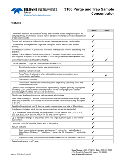


© Copyright 2026