
USER MANUAL VU01 Hukseflux
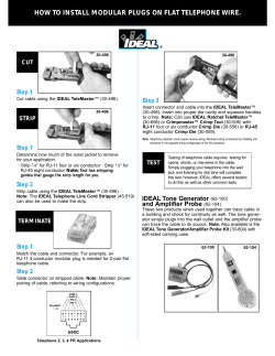
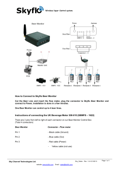
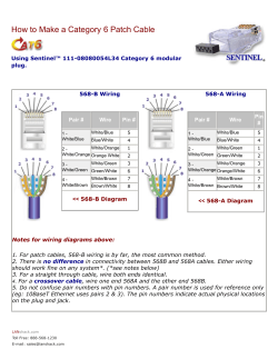
Hukseflux
Thermal Sensors
USER MANUAL VU01
Ventilation unit
for SR20 pyranometers and IR20 pyrgeometers
Copyright by Hukseflux | manual v1406 | www.hukseflux.com | [email protected]
Warning statements
Always power off the ventilation unit when
conducting maintenance or installing VU01.
VU01 is designed for use with standard SR20, IR20
& IR20WS sensors. VU01 is not meant to be used
with other pyranometers and pyrgeometers,
including –TR versions.
Accidentely exchanging the VU01 cable and sensor
cable will not damage the sensor, but the instrument
and ventilation unit will not function.
In case of cable replacement / extension beyond
5 m, please note that the voltage drop across the
VU01 cable becomes significant; a higher voltage
power supply may have to be used.
vu01 manual v1406
2/23
Contents
Warning statements
Contents
List of symbols
Introduction
Ordering and checking at delivery
1
Ordering VU01
1.1
Included items
1.2
Options
1.3
Quick instrument check
1.4
Instrument principle and theory
2
Specifications of VU01
3
Specifications of VU01
3.1
Dimensions of VU01
3.2
Standards and recommended practices for use
4
Installation of VU01
5
Installation of the ventilation unit
5.1
Installation of the sensor
5.2
Installation of the VU01 cover
5.3
Electrical connection of VU01
5.4
Power supply and cable length
5.5
Using the alarm signal
5.6
Maintenance and trouble shooting
6
Recommended maintenance and quality assurance
6.1
Trouble shooting
6.2
Appendices
7
Appendix on filter replacement
7.1
Appendix on tools for VU01
7.2
Appendix on spare parts for VU01
7.3
Appendix on cable extension / replacement
7.4
Appendix on conditions of sale: warranty and liability
7.5
EC declaration of conformity
7.6
vu01 manual v1406
2
3
4
5
7
7
7
7
7
8
9
9
10
11
12
12
12
13
14
14
15
17
17
17
19
19
19
19
20
21
22
3/23
List of symbols
Quantities
Symbol
Unit
Voltage output
Electrical resistance
Current
Time in seconds
Fan speed
U
Ra
I
t
N
V
Ω
A
s
1/min
Subscripts
UA
U A,high
U A,low
Ng
I sink
vu01 manual v1406
alarm operating voltage
alarm signal high
alarm signal low
alarm trip speed limit
sink current
4/23
Introduction
VU01 is a high-quality ventilation unit for use with pyranometer model SR20 and
pyrgeometer models IR20 and IR20WS. Its purpose is to improve the dependability of
the measurement. Measurement accuracy improves because offsets are reduced.
Reliability benefits from prevention of dew and frost formation and quick evaporation and
sublimation of water and snow. ISO/TR 9901 “Solar Energy - Field Pyranometers Recommended practice for use” recommends use of ventilators where high accuracy and
reliability are required.
VU01 provides an airflow over the instrument body and dome and has a 5 W and a 10 W
heater on board to heat the air. The VU01 ventilation unit runs on 12 VDC voltage. VU01
may be used in combination with Hukseflux’ SR20 secondary standard pyranometers and
IR20 and IR20WS research grade pyrgeometers.
Ventilation promotes thermal equilibrium between all components of radiometers, and
thereby reduces zero offsets. Dew and frost formation is prevented. Additional heating
will promote evaporation of water droplets and sublimation of snow. It should be noted
that heating in combination with pyranometers will lead to increased thermal offsets, so
heating is only recommended if necessary.
Using VU01 is easy. The ventilator is generally used continuously; the heater is typically
controlled by the datalogger. ISO/TR 9901 “Solar Energy - Field Pyranometers Recommended practice for use” recommends use of ventilators where high accuracy and
reliability are required. More details can be found in paragraph 5.2.2 and annex A. The
Baseline Surface Radiation Network, BSRN, recommends ventilation for radiometers in its
BSRN operations manual v2.1.
Figure 0.1 VU01 ventilation unit with SR20 secondary standard pyranometer
vu01 manual v1406
5/23
VU01 is designed, using high-quality materials, in agreement with the recommendations
of ISO/TR 9901 and BSRN. The footprint of VU01 is small, which prevents accumulation
of snow. The ventilator power is relatively high in order to increase the airflow. The
heaters should be activated using external relays. The alarm output may be used to
monitor rotation of the fan. The high / low voltage output may be adjusted by the user
with a fixed resistor.
For specifications of pyranometers and pyrgeometers and general considerations
concerning site selection and maintenance fur such instruments, please consult the SR20
and IR20 manuals.
vu01 manual v1406
6/23
1
Ordering and checking at delivery
1.1
Ordering VU01
The standard configuration of VU01 is with 5 metres cable. Options are: longer cable (in
multiples of 5 m) and a pack of 5 filters.
Supply of products is subject to Hukseflux’ General Conditions of Sale. The product
warranty (involving repair or replacement without charge for product or working hours) is
24 months.
Hukseflux does not accept any liability for losses or damages related to use of the
supplied products. See the appendix and Hukseflux’ General Conditions of Sale for
detailed statements on warranty and liability.
1.2
Included items
Arriving at the customer, the delivery should include:
• ventilation unit VU01
• cable of the length as ordered
• sensor mounting hardware (affixed to VU01):
- (1 x) sensor mounting plate and gasket
- (4 x) M5x10 screw
• torx key T25 (1 x)
• VU01 mounting hardware:
- (2 x) M5x60 screw
- (2 x) M5 retaining torque nut
- (4 x) ø 5 x 10⁻³ m washer
• spare filter (1 x)
• product certificate
• any other options as ordered
1.3
•
•
Options
longer cable, in multiples of 5 metres (please note the voltage drop of cabling).
Specify total cable length. In case of cables longer than 15 m consult Hukseflux.
pack of 5 filters. Specify order number VU01F.
1.4
Quick instrument check
A quick test of the ventilation unit can be done by using a simple hand held multimeter
and a 12 VDC power supply, using the wiring diagram in chapter 5 of this manual.
1.
2.
3.
Check the electrical resistance of the heaters; 27 Ω each
Connect fan wires to a 12 VDC power supply: the fan should run
When running, an alarm signal can be measured
(see chapter 5 for the optional alarm configuration instructions)
vu01 manual v1406
7/23
2
Instrument principle and theory
3
2
4
1
10
5
9
6
8
6
7
Figure 2.1 Overview of VU01 with SR20:
(1)
(2)
(3)
(4)
(5)
(6)
(7)
(8)
(9)
(10)
SR20
SR20
SR20
VU01
VU01
VU01
VU01
VU01
VU01
VU01
cable
connector
dome
cover
fixation of cover
levelling feet
filter retainer
ventilator, heaters and filter replacement system (below cover)
connector
cable and cable connector
Ventilation promotes thermal equilibrium between all components of radiometers, and
thereby reduces zero offsets. Dew and frost formation is prevented. Additional heating
will promote evaporation of water droplets and sublimation of snow. It should be noted
that heating in combination with pyranometers will lead to increased thermal offsets, so
heating is only recommended if necessary.
vu01 manual v1406
8/23
3
Specifications of VU01
3.1
Specifications of VU01
VU01 is a high-quality ventilation unit that may be used with pyranometer model SR20
and pyrgeometer models IR20 and IR20WS. Its purpose is to improve the dependability
of the measurement. Measurement accuracy improves because offsets are reduced.
Reliability benefits from prevention of dew and frost formation and quick evaporation and
sublimation of water and snow. For specifications of pyranometers and pyrgeometers,
please consult the SR20 and IR20 manuals.
Table 3.1.1 Specifications of VU01 (continued on next page)
VU01 SPECIFICATIONS
Compatible instruments
Excluded
Compliance with standards
Rated operating power
Rated operating voltage range
Rated operating temperature range
Alarm output
Heater
Increase of air temperature
Zero offset a SR20 ventilated
Offset SR20 by heating
Offset SR20 by heating
Offset IR20 by heating
Offset IR20 by heating
Cable resistance
Voltage drop at 7.8 W ventilation
Voltage drop at 10 W heating power
Footprint diameter
Fan speed
Standard cable length (see options)
Cable diameter
VU01 connector
VU01 connector type
Cable connector
Cable connector type
Connector protection class
Cable replacement
IP protection class VU01
Gross weight including 5 m cable
Net weight including 5 m cable
Packaging
vu01 manual v1406
SR20, IR20, IR20WS
-TR versions
ISO/TR 9901
BSRN operations manual
7.8 W at 12 VDC (unheated)
10.8 to 13.2 V
-40 to +70 oC
high / low adjustable voltage (optional use)
5 and 10 W at 12 VDC (optional use) (with remote relays)
0.5 oC at 0 W heating; 1.0 oC at 5 W heating;
1.5 oC at 10 W heating
2.5 W/m2 at 0 W heating
-2 W/m2 at 5 W heating
-4 W/m2 at 10 W heating
0 W/m2 at 5 W heating
0 W/m2 at 10 W heating
0.3 Ω/m (2 x 0.15 Ω/m)
0.2 V/m
0.24 V/m
0.17 m
5050 to 5400 1/min at 12 VDC (depends on supply voltage)
5m
5.3 x 10⁻³ m
M16 straight connector, male thread, 10-pole
HUMMEL AG 7.820.400.000 straight connector, male
thread, for cable 5 to 9 x 10⁻³ m
M16 straight connector, female thread, 10-pole
HUMMEL AG 7.810.300.00M straight connector, female
thread, for cable 3 to 6 x 10⁻³ m, special version
IP 67 / IP 69 K per EN 60 529 (connected)
replacement cable with cable connector can be ordered
separately from Hukseflux
IP 54 (SR20 and IR20: IP 67)
1.55 kg
1.35 kg
box of (200 x 200 x 150) x 10-3 m
9/23
Table 3.1.1 Specifications of VU01 (continued)
VERSIONS / OPTIONS / ACCESSORIES
Longer cable, in multiples of 5 metres
Pack of 5 filters
Dimensions of VU01
124
3.2
option code = total cable length
(please note the voltage drop of cabling; in case of cables
longer than 15 m consult Hukseflux)
order code = VU01F
Ø 165
140
Ø5
Figure 3.2.1 Dimensions of VU01 in 10-3 m.
vu01 manual v1406
10/23
4
Standards and recommended practices
for use
Pyranometers are classified according to the ISO 9060 standard and the WMO-No. 8
Guide. In any application the instrument should be used in accordance with the
recommended practices of ISO, IEC, WMO and / or ASTM.
Pyrgeometers are not subject to standardisation. The World Meteorological Organization
(WMO) is a specialised agency of the United Nations. It is the UN system's authoritative
voice on the state and behaviour of the earth's atmosphere and climate. WMO publishes
WMO-No. 8; Guide to Meteorological Instruments and Methods of Observation, in which
paragraph 7.4 covers "measurement of total and long-wave radiation". For ultra high
accuracy measurements, the following manual may serve as a reference: Baseline
Surface Radiation Network (BSRN) Operations Manual, Version 2.1, L. J. B. McArthur,
April 2005, WCRP-121, WMO/TD-No. 1274. The BSRN manual also includes chapters on
pyrgeometer installation and calibration.
Table 4.1 Standards with recommendations for instrument ventilation
STANDARDS FOR INSTRUMENT USE FOR SOLAR AND LONGWAVE RADIATION
ISO STANDARD
EQUIVALENT
ASTM STANDARD
WMO
ISO/TR 9901:1990
Solar energy -- Field
pyranometers -- Recommended
practice for use
ASTM G183 - 05
Standard Practice for Field
Use of Pyranometers,
Pyrheliometers and UV
Radiometers
WMO-No. 8; Guide to
Meteorological Instruments
and Methods of Observation,
chapter 7, measurement of
radiation, 7.3 measurement
of global and diffuse solar
radiation, 7.4 measurement
of total and long-wave
radiation
BSRN Operations Manual,
Version 2.1, April 2005
vu01 manual v1406
11/23
5
Installation of VU01
5.1
Installation of the ventilation unit
Once the VU01 cover is removed, the ventilation unit can be mounted to a flat mounting
surface using the supplied VU01 mounting hardware.
Optionally a large hole can be made by the user in the mounting surface under VU01 if
obstruction of the airflow from the sides is expected, for example by snow buildup.
The hole diameter should not exceed 120 x 10-3 m.
5.2
•
•
•
•
•
Installation of the sensor
Remove the sun screen of SR20 / IR20 / IR20WS.
Attach the sensor mounting plate to the bottom of the sensor using two M5x10
screws (See Figure 5.2.1). A T25 torx key to do so is included with VU01.
Affix the sensor with the sensor mounting plate to the ventilation unit using two
M5x10 screws (See Figure 5.2.1 for placement of the gasket).
The sensor cable connector should be positioned alongside the engraved “cable”
marking on the VU01 base.
The VU01 levelling feet can be used to finetune the sensor levelling. Even with the
VU01 cover installed (see next page), the sensor can still be levelled since the
instrument’s bubble level is still visible below the VU01 cover.
Figure 5.2.1 VU01 base with gasket, sensor mounting plate and SR20 pyranometer: the
instrument is affixed to VU01 using four M5x10 screws.
vu01 manual v1406
12/23
5.3
Installation of the VU01 cover
To install:
• Connect the sensor cable connector (3) to the sensor, guiding the connector through
the designated hole in the VU01 cover
• Position the cover (2) at an angle on positioning pin (5)
• Close the cover using positioning pin (5) as swivel point
• Affix the cover using thumbscrew (1)
• Connect the VU01 cable connector to the VU01 connector (4)
To remove cover:
• Loosen thumbscrew (1) by turning counterclockwise until the tapered part of the
thumbscrew is ejected from the ventilation unit base
• Lift the cover, tilting around positioning pin (5)
2
3
1
4
5
Figure 5.3.1 Installation and removal of ventilator cover: (1) VU01 thumbscrew, (2)
VU01 cover, (3) sensor connector, (4) VU01 connector, (5) VU01 positioning pin.
Figure 5.3.2 Cutaway of VU01 showing internal components and SR20 pyranometer.
vu01 manual v1406
13/23
5.4
Electrical connection of VU01
The cables of VU01 and SR20 / IR20 have an identical M16 straight connector. Do not
connect the VU01 connector to the SR20 / IR20 cable and do not connect the SR20 /
IR20 connector to the VU01 cable; both VU01 and SR20 / IR20 will not function.
Cables generally act as a source of distortion, by picking up capacitive noise. We
recommend keeping the distance between a datalogger or amplifier and the sensor as
short as possible. For cable extension, see the next paragraph and appendix on this subject.
Table 5.4.1 The electrical connection of VU01. The heaters and alarm signal are not
necessarily used; their use is optional.
PIN
WIRE
VU01
CONNECTION
1
Brown
fan [+]
12 VDC [+]
4
Yellow
fan [−]
common [−]
6
Blue
alarm
see figure 5.6.1
2
Red
heater 1 [+]
12 VDC [+]
8
Grey
heater 1 [−]
common [−]
3
Pink
heater 2 [+]
12 VDC [+]
5
Green
heater 2 [−]
common [−]
7
White
not connected
not connected
9
Black
shield
ground
Optionally an alarm signal can be connected by the user as shown in the wiring diagram
in figure 5.6.1. See paragraph 5.6 in this manual on using the alarm signal.
5.5
Power supply and cable length
In case of cable replacement or extension beyond 5 m, please note that the voltage drop
across the regular VU01 cable becomes significant and that a higher voltage power
supply or a thicker cable may be used.
Using a 12 VDC power supply and a cable of 5 m, the voltage drop is around 1 V and the
VU01 ventilator will effectively run on 11 VDC. The ventilator will continue running down
to a supply voltage of around 7.5 VDC; the flow rate will however decrease significantly
(based on power by a factor 4). This level is reached at a cable length of 20 m.
We recommend to adapt the supply voltage or use cables with a lower resistance per
meter when working with cable lengths longer than 15 m, the ventilator then works at 9
VDC, at a flow rate of 80 % relative to 5 m cable.
vu01 manual v1406
14/23
5.6
Using the alarm signal
Using the alarm signal is optional: the alarm output may be used to monitor rotation of
the fan. The VU01 alarm emits a high, continuous signal during trouble-free operation of
the fan. When opting for using the alarm signal, see figure 5.6.1 and paragraph 5.4 for
the electrical connection of VU01.
To use the alarm, the user must supply an alarm operating voltage U a of maximum 60
VDC. An external load resistor is required to make sure the sink current is between 2 and
20 x 10-3 A. For example, using a 1000 Ω load resistor will allow alarm operating
voltages between 2 and 20 VDC.
A signal, U A,high , is provided when the fan speed N is above the alarm trip speed limit N g
of 1500 rotations per minute. The signal is equal to the alarm operating voltage U A .
When the fan is running slowly or not at all, a low signal U A,low is provided.
The alarm will only function when VU01 itself is powered.
Table 5.6.1 Alarm signal variables
VARIABLE
DESCRIPTION
VALUE
Alarm operating voltage [V]
≤ 60 V
U A,high
Alarm signal high [V]
UA
U A,low
Alarm signal low [V]
≤ 0.4 V
Sink current [A]
2 to 20 x 10-3 A
UA
I sink
Ra
Resistor [Ω]
N
Fan speed [1/min]
Ng
Alarm trip speed limit [1/min]
1500 min-1 ± 100 min-1
t2
Alarm start-up delay time [s]
< 15 s
fan [+]
brown
Ra
I sink
UA
blue
U A,high
or
fan [-]
U A,low
yellow
Figure 5.6.1 Wiring diagram required to use VU01’s alarm function. The use of the
alarm signal is optional. See table 5.4.1 for the electrical connection of VU01.
vu01 manual v1406
15/23
N [1/min]
(Fan speed)
Ng
time [s]
[V]
U A, high
U A, low
time [s]
Figure 5.6.2 An alarm signal, U A,high , is provided when the fan speed N is above the
alarm trip speed limit N g . Using the alarm signal is optional.
vu01 manual v1406
16/23
6
Maintenance and trouble shooting
6.1
Recommended maintenance and quality assurance
For maintenance and trouble shooting of pyranometers and pyrgeometers consult the
SR20 and IR20 manuals.
When conducting maintenance on VU01, always power off the ventilation unit.
Powering off VU01 may be done by disconnecting the VU01 connector.
Table 6.1.1 Recommended maintenance of VU01
MINIMUM RECOMMENDED VENTILATION UNIT MAINTENANCE
INTERVAL
SUBJECT
ACTION
1
1 week
check
check the operational status of the ventilator and heaters by
checking the optional alarm signal or by on-site inspection
2
1 week
cleaning
clean ventilator cover and ensure air inlet is free of
obstructions such as leaves or snow buildup
3
1 year
filter
replace ventilator filter, as described in the appendix
6.2
Trouble shooting
Table 6.2.1 Trouble shooting for VU01
PROBLEM
SOLUTION
Fan and / or heaters do not function
check wiring for correct connection of [+] and [-]
check power supply
Fan does not work
check for obstructions of fan
Fan provides little airflow
check for obstructions of airflow
replace filter if clogged
check wiring connections
vu01 manual v1406
17/23
vu01 manual v1406
18/23
7
Appendices
7.1
Appendix on filter replacement
To replace the filter:
•
•
•
•
•
•
•
power off the ventilation unit by disconnecting the VU01 connector
insert the tip of a flat screwdriver in the designated slot of the front side the filter
retainer
turn the screwdriver 90° to detach the filter retainer from the finger guard
replace the used filter cloth with a fresh filter (spare part VU01F)
slide the filter retainer under the ventilation unit
take care to position the slot to the front (thumb screw) side of the ventilation unit
lift and click the filter retainer in place
7.2
Appendix on tools for VU01
Table 7.2.1 Specifications of tools for VU01
tooling required for sensor mounting and removal
torx key T25 (included)
tooling required for fixing VU01 to platform
hex key 3
tooling required for filter replacement
screwdriver, flat
7.3
•
•
•
•
•
Appendix on spare parts for VU01
levelling feet (set of 2)
static foot
cover
pack of 5 filters
cable with cable connector (specify length in multiples of 5 m; in case of cables longer
than 15 metres please consult Hukseflux)
vu01 manual v1406
19/23
7.4
Appendix on cable extension / replacement
When opting for cable extension or cable replacement please note the voltage drop in
cabling. In case of cables longer than 15 metres consult Hukseflux. See the specific
paragraph in this manual about power supply and cable length.
The cable of VU01 is equipped with a M16 straight connector. In case of cable
replacement, it is recommended to purchase a new cable with cable connector at
Hukseflux. An alternative is to choose for a Do-it-yourself (DIY) approach; please ask for
the DIY connector assembly guide. In case of cable extension, the user may choose
between purchasing a new cable with cable connector at Hukseflux or extending the
existing cable himself. Please note that Hukseflux does not provide support for DIY
connector- and cable assembly.
Cables act as a source of distortion by picking up capacitive noise. Keep the distance
between data logger or amplifier and sensor as short as possible.
VU01 connector, cable and cable connection specifications are summarised below.
Table 7.1.1 Preferred specifications for VU01 cable replacement and extension
General replacement
please order a new cable with connector at Hukseflux or choose for a DIY
approach. In case of DIY replacement by the user see connector
specifications below and ask for the DIY connector assembly guide
General cable extension please order a new cable with connector at Hukseflux or solder the new
cable conductors and shield to the original sensor cable and make a
connection, using adhesive-lined heat shrink tubing, with specifications
for outdoor use. Always connect shield
Connectors used
VU01: M16 straight connector, male thread, 10-pole, HUMMEL AG
7.820.400.000 straight connector, for cable 5 to 9 x 10⁻³ m
cable: M16 straight connector, female thread, 10-pole, HUMMEL AG
7.810.300.00M straight connector, for cable 3 to 6 x 10⁻³ m, special
version
Cable
8-wire, shielded, with copper conductors (at Hukseflux 8-wire shielded
cable is used, of which 2 wires are used to power the fan, 4 for heating
and 1 for the alarm signal)
Conductor resistance
< 0.1 Ω/m
Length
cables should be kept as short as possible, in case of cables longer than
15 m consult Hukseflux.
Outer sheath
with specifications for outdoor use
(for good stability in outdoor applications)
vu01 manual v1406
20/23
7.5
Appendix on conditions of sale: warranty and liability
Delivery of goods is subject to Hukseflux General Conditions of Sale.
Hukseflux has the following warranty and liability policy:
Hukseflux guarantees the supplied goods to be new, free from defects related to bad
performance of materials and free from faults that are clearly related to production and
manufacturing. Warranty on products is valid until 24 months after transfer of ownership.
The warranty does not apply if the application involves significant “wear and tear”, if it
involves use outside the specified range of application, or if it involves accidental damage
or misuse. The warranty expires when anyone other than Hukseflux makes modifications
to or repairs the products.
Hukseflux is in no event liable for damages, to its customers or anyone claiming through
these customers, associated to the goods or services it supplies.
vu01 manual v1406
21/23
7.6
EC declaration of conformity
We,
Hukseflux Thermal Sensors B.V.
Delftechpark 31
2628 XJ Delft
The Netherlands
in accordance with the requirements of the following directive:
2004/108/EC
The Electromagnetic Compatibility Directive
hereby declare under our sole responsibility that:
Product model:
Type:
VU01
Ventilation unit
has been designed to comply and is in conformity with the relevant sections and
applicable requirements of the directive.
Kees VAN DEN BOS
Director
Delft
October 24, 2013
vu01 manual v1406
22/23
© 2014, Hukseflux Thermal Sensors B.V.
www.hukseflux.com
Hukseflux Thermal Sensors B.V. reserves the right to change specifications without notice.


© Copyright 2026