
Document 360089
Feb. 28, 1939. ‘
R. |_. STIF‘FLER
2,148,658
VEHICLE WHEEL
Filed Nov. 18, 1937
I
AW
wrimM"Em."
U
\
-\”’ By
‘
I
INVENTOR:
ZZZ WW
W r’
A TTORNEYS.
Patented Feb. 2a, 1939
M
I
. 2,148,658
UNITED STATES PATENT“ oFFlci: _
I
i
Ralph
I
L. Stif?er, Lansdowne, Pa.
Application 202$:
fell)
0. _ ,
'
_
My invention relates generally to wheel structures and more particularly to wheel structures
having demountable rims on which tires are
ing rings l1 and it which are in turn supported
by a pressed fit within element II as shown.
The‘ disc portion 2 has strengthening ribs 2.
mounted.
formed therein and radiating, from the hub I in
"
a
' ‘
5
My invention is directed toward the problem
- of simple and easy replacement of worn tires on
a manner suggesting the spokes of a wheel. The |
circumierential edge of the disc portion I is bent
the rubber-tired trucks which are in use about
railway stations and in other industrial uses.
It is important that the change. of tires be ac-
v10 complished quickly and" without extensive and
heavy apparatus. The pressed-0n type of tire
which is frequently met with in industry limits
over and formed into an annular ?ange 22 which
is duplicated on the other side .0! the disc 901'
tion 3 by an annular ?ange 22 formed on a re
movable ring 2i. The ring 24 is secured to the 10
disc portion 3 by a fastening means composed of
bolts 26 and nuts 21 with lock washers of a usual
~ tire changing to stations having the necessary
tus which cannot be widely dismbuted
type.
16 due to cost factors,
°
" My invention wgrvides a rugged wheel structure
which permits
The ?anges 22 and 22 incline downward
toward each'other so, that the outside edges of
the ?anges 22 and 23 are higher than the inner ll,
edges of the flanges 22 and 23- The ansle which "
quick and eiiicient tire change
without special apparatim and this is it; mam
object. other objects 0! my invention are 51111..
a so Ducity of assembly and of manufacture. Still
these ?anges n and. 23 make with ‘The mngmuu'
rial axis of the wheel is comparatively small in
order to provide full support for the rim member
4 which. is correspondingly formed to at the so
other advantages will appear from the following
?anges 22 and 23. In the illustrated embodiment '
detailed description of a preferred embodiment of j of my invention, the angle of the ?anges 22 and
my invention, reference being had t0 the accom. ' 23 with the wheel axis is about 9". The size of
'panying drawing.
'
'
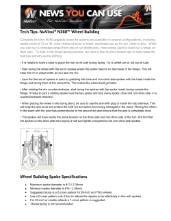
as Fig. 1 or the drawing shows a partial side e1eva_
the rim member 4 is such that the removable ring
24 cannot be drawn up to a contacting relation 5 .
tion of a wheel constructed according to my in- with the disc Portion 3-‘ This insures 8 tight re
vention.
'taining lit for the rim member I as the bolts 26
Fig. 11 is a section‘ taken as indicated by the and nuts. 21' are taken up- The 11m member 4
mow; 11.41 of F1; 1
‘30
- -
has a tire 5 of rubber or similar substance.
Inthe drawing thereis Shown awheel equipped
rubber is the material chosen. the tire I is vul- 30
with a roller bearing of 9, conventional type which
need not be described in detail, The wheel com
slabs of a, hub >l mounted rigidly on an axle 2’ a
canized to the rim member 4. Of course any other
means well known in the art for attaching’ the
tire 5 to the rim member ti could be used instead
disc portion 2 mounted on the hub I, and a rim
of vulcanizmg-
as member l having a tire 5 attached thereto.
The hub _l consists of two circular elements ID
'
-
The operation of my invention iollows clearly as
from the above descriptiim but a kw further com
' rigidly attached to and spaced longitudinally . ments may further clarify the advantages thereof.
along the axle 2. These elements lg Support gimp
lar elements II by means of rollers n positioned
40 between the elements [0 and H. The elements H
If‘ are rigidly attached to the inside of the cylin-
drlcal element‘ II which is the ‘hub proper.‘ It
will be noted that a circular’ area is' formed‘
around the axle 2 and con?ned within the ‘cylin-
m We a by we
w
H
the ends of the hub I. This spaceis for lubrica“new and the mbricalms substarise is
forced mm’ it through a‘ valve ?tting It
‘50
In order to prevent the lubricating substance
when it is desired ‘to change a'tire, one of the
spare. rim members l_ having a tire i is taken to.
the truck for the tire change. Then the nuts 21 40
and
boltsand
2‘the
of removable
the wheel ring
in question
aretaken
un
screwed
2| is easily
off. Any slight binding is relieved by inserting a
screw driver or similar tool into the space between
.
~
1.1
u
$855.2?“ii2t‘t2. ‘5m .22: a...“
.
‘i
?'m member s which is‘ then removed_ The new
tire is positioned on the ?ange z: and tapped '
' into a‘shug fit. The ring 24 is then replaced and
the nuts. :1 and bolts 26 tightened up.
from running 011i; from the rollers l2 over the
change is then‘ com 19133,
The 50
No special tools are '
wheel surface, a retaining ring ii of felt or of a
required and the change occupies but a few min
similar substance is provided. This ring it is
utes.v The importance oi'the small inclination
.- in easy contact with the surface of the element
of the ?anges 22 and 22 must not be overlooked.
u ll and. is held in place between two metal retain-
If a deep pronounced V-surfa'ce were provided by
.
' 2
2,148,658
the ?anges 22 and 23, the'advantages of a pressed
?t would be
from‘ their respective
circumferential edges to
n
provide
the the like a' pressed ?t assembly hut/without the of said ?anges with the wheel axis being com
dl?iculties in changing tires
paratively slight, a tire supporting rim mounted
Which/are inhei‘en/t , on said ?anges and having its inner contacting
surface conforming substantially in shape to said
shallow
.
,
8‘
{said parts
10
2. A vehicle wheel as de?ned in claim 1 wherein .
the annular ?ange formed around the edge of
_ the wheel
disc portion is inclined approximately
of nine degrees with respect to the
15
'
dished radial strength
emng ribs surrounding said hub and simulating
?ange formed around the
of said disc portion, a re
movable ring attached to said disc portion having
.an opposinglydirected ?ange to said ?rst men
tioned ?ange,
20
?anges each inclining inward
RALPH L. s.


© Copyright 2026