
PS and PL Ethernet Performance and Jumbo Frame Support
Application Note: Zynq-7000 AP SoC
PS and PL Ethernet Performance and Jumbo
Frame Support with PL Ethernet in the
Zynq-7000 AP SoC
XAPP1082 (v3.0) January 7, 2015
Summary
Authors: Anil Kumar A V, Radhey Shyam Pandey, Srinivasa Attili
The focus of this application note is on Ethernet peripherals in the Zynq®-7000 All
Programmable (AP) SoC. This application note describes using the processing system (PS)
based gigabit Ethernet MAC (GEM) through the extended multiplexed I/O (EMIO) interface with
the 1000BASE-X physical interface using high-speed serial transceivers in programmable logic
(PL). This application note also describes the implementation of PL-based Ethernet supporting
jumbo frames.
The designs provided with this application note enable the use of multiple Ethernet ports, and
provide kernel-mode Linux device drivers.
Introduction
The Zynq-7000 AP SoC device is based on the Xilinx® All Programmable SoC architecture.
These products integrate a dual core ARM® Cortex™-A9 MPCore™ based PS and PL in a
single device.
The PL includes the programmable logic, configuration logic, and associated embedded
devices. The PS comprises the processor unit, on-chip memory, external memory interfaces,
and peripheral connectivity interfaces including two gigabit ethernet controllers (GEM), which
access PL signals through the extended multiplexed I/O (EMIO) interface to connect different
physical interfaces.
In the designs provided with this application note, the PS-GEM0 is connected to the Marvell
PHY through the reduced gigabit media independent interface (RGMII), which is the default
setup for the ZC706 board. The focus of this application note is the design of additional
Ethernet ports.The designs described in this application note are:
•
PS Ethernet (GEM1) that is connected to a 1000BASE-X physical interface in PL through
an EMIO interface
•
PL Ethernet implemented as soft logic in PL and connected to the 1000BASE-X physical
interface in PL
© Copyright 2013–2015 Xilinx, Inc. Xilinx, the Xilinx logo, Artix, ISE, Kintex, Spartan, Virtex, Vivado, Zynq, and other designated brands included herein are trademarks of Xilinx
in the United States and other countries. AMBA, AMBA Designer, ARM, ARM1176JZ-S are trademarks of ARM in the EU and other countries. HDMI, HDMI logo, and
High-Definition Multimedia Interface are trademarks of HDMI Licensing LLC. All other trademarks are the property of their respective owners.
XAPP1082 (v3.0) January 7, 2015
www.xilinx.com
1
Introduction
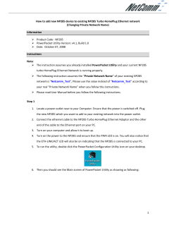
Figure 1 shows the various Ethernet implementations on the ZC706 board.
Note: The three Ethernet links cannot be active at the same time because the ZC706 board offers only
one SFP cage for the 1000BASE-X PHY. The PS-GEM0 is always tied to the RGMII Marvell PHY. The
PS-GEM1 and the PL Ethernet share the 1000 BASE-X PHY so only two Ethernet Links can be active at
a given time.
X-Ref Target - Figure 1
3URFHVVLQJ6\VWHP
8$57
0HPRU\
,QWHUIDFH
$38
&HQWUDO
,QWHUFRQQHFW
[LOLQ[BHPDFSV
36*(0/LQN
*,&
0DUYHOO
5*0,,
*0,,WR
0,2 5*0,,
*0,,
9LD
(0,2
'0$
*(0
ELW*3
$;,0DVWHU
'0$
*(0
$;,,QWHUFRQQHFW
[LOLQ[BHPDFSVBHPLR
3/WR0HPRU\
,QWHUFRQQHFW
ELW+3$;,6ODYH
$;,,QWHUFRQQHFW
36*(0/LQN9LD(0,2
6)3
*7;
7UDQVFHLYHU
%$6(;
$;,'0$
3/(WKHUQHW/LQN
[LOLQ[BD[LHQHWBPDLQ
$;,(WKHUQHW
*0,,
3URJUDPPDEOH/RJLF
;BB
Figure 1:
Zynq-7000 AP SoC Ethernet Interface
Reference Clock Generation
The design uses the GTX transceiver X0Y10 on the Zynq-7000 AP SoC connected to the SFP
cage on the ZC706 board for 1000BASE-X transceivers. The GTX transceiver reference clock
(125 MHz differential) is generated from the Si5324 jitter attenuator on the ZC706 board. The
clock divider values are adjusted to generate 125 MHz from the 114.285 MHz crystal
connected to the Si5324.
The Si5324 driver programs the device over the I2C interface to generate the required clock
value. This driver initializes the Si5324 once at boot time. At boot time, the driver probe function
is invoked by the I2C framework. The probe function fetches the client address from the device
tree and programs the hardware registers with the relevant values. See [Ref 1] for details on
Si5324.
XAPP1082 (v3.0) January 7, 2015
www.xilinx.com
2
Using PS GEM Through EMIO
Using PS GEM
Through EMIO
This section describes how to use the PS Ethernet block GEM1 with the PL PHY through the
EMIO interface. The PS Ethernet block is exposed to the PL through the EMIO, GMII, and the
management data input/output (MDIO) interfaces. The 1000BASE-X PCS/PMA core is used as
Ethernet physical media, and uses the high-speed serial transceivers to access the SFP cage
on the ZC706 board. The connection between the SFP cage to a standard Ethernet LAN is
through an SFP-to-RJ45 converter module.
Hardware Design
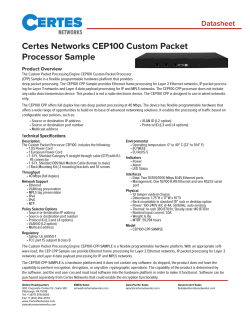
Figure 2 shows the design block diagram. The GMII interface connects the PHY and PS EMAC
through the EMIO pins. The GEM1 block is enabled while generating the hardware system. See
the Checksum Offloading section in the Gigabit Ethernet Controller chapter in [Ref 2] for
information on checksum offloading in PS_GEM. See the chapter on using 1000BASE-X PHY
with Zynq-7000 AP SoC in [Ref 3] for more information.
X-Ref Target - Figure 2
6RIWZDUH'ULYHU)RU/LQX[
6WDQGDUG1HWZRUNLQJ
$SSOLFDWLRQ
'HYLFH7UHH
/LQX[,PDJH
7&3,36WDFN
36(WKHUQHW'ULYHU
3URFHVVLQJ6\VWHP
*0,,B7;
*0,,B7;B&/.
*0,,B5;B&/.
(WKHUQHW
0$&
*(0
*0,,B5;
%$6(;
3&630$2U
6*0,,
6)3
*
7
0+]*7
5HIHUHQFH&ORFN
0',2
0'&
6L
3URJUDPPDEOH/RJLF
;BB
Figure 2:
Design Block Diagram
Software Design
The design uses the xilinx_emacps_emio.c driver code (included with the reference
design zip file), which is based on the PS GEM driver xilinx_emacps.c.
To enable GEM1 through the EMIO interface, specific registers must be programmed. This is
part of the PS configuration data used by the Zynq-7000 AP SoC first stage bootloader (FSBL).
On system generation with the EMIO enabled for the second GEM, the ps7_init.tcl file
that is available on SDK export of the hardware design, includes the register settings by default,
which are:
•
To select the EMIO as the source of receive clock, data, and control signals:
Set SLCR.GEM1_RCLK_CTRL[SRCSEL] bit to 1
•
To select the EMIO as the source to generate reference clock:
Set SLCR.GEM1_CLK_CTRL[SRCSEL] bit to 3’b1xx
where ‘x’ is don’t care (can be either 1 or 0)
XAPP1082 (v3.0) January 7, 2015
www.xilinx.com
3
Using PS GEM Through EMIO
The xilinx_emacps_emio driver uses the DMA controller attached to the GEM Ethernet
controller in the PS. This driver is responsible for several functions, including DMA descriptor
rings setup, allocation, and recycling. The interrupt handling is done only for the PS GEM
events, as the interrupt status implicitly reflects the DMA events as well. Additionally, the device
tree is updated to include PS-GEM1 with relevant parameters.
Note: To support other PL physical interfaces, such as TBI, the hardware design and device tree must be
edited. The PHY specific initialization is handled in the phylib subsystem in the Linux driver and
information regarding the PHY can be provided in the device tree. To use the phylib subsystem for PHY
programming, the phylib subsystem must support the PHY initialization routine for the desired PHY. If not,
the PHY initialization routine should be implemented in the driver.
Linux Driver
A monolithic Linux device driver is provided for this design. Figure 3 shows the software
architecture for the PS Ethernet interfaces.
X-Ref Target - Figure 3
8VHU/HYHO
SURFGHY
/LQX[.HUQHO
6FKHGXOHU
SURFLQWHUIDFH
GHYLQWHUIDFH
'ULYHU0RGXOH
6RIW,54
'R,54
7UDQVPLW
,65
5HFHLYH
,65
7UDQVPLW
7DVNOHW
5HFHLYH
7DVNOHW
7UDQVPLW
7RS+DOI
5HFHLYH
7RS+DOI
HWKWRROVXSSRUW
'0$$FFHVV
7;%'5LQJ
PDQDJHPHQW
5;%'5LQJ
PDQDJHPHQW
(WKHUQHW'ULYHU
5HFHLYH
2YHUIORZ
+DUGZDUH
7UDQVPLW
2YHUIORZ
*,&,QWU&RQWUROOHU
(WKHUQHW7UDQVPLW
'0$&KDQQHO
7UDQVPLW
'0$
(WKHUQHW'0$
ILQLVKGRQHKDOW
HUURUHYHQWV
3+</LEUDU\
(7+722/
0,,3+<
+RRNV
*HW6HWVHWWLQJV
PGLRBUHDG
*HWGUYLQIR
PGLRBZULWH
*HW/LQN
PGLRBUHVHW
*HW6HW:2/
DGMXVWBOLQN
5HFHLYH
'0$
*0,,
3+<
0,,,QWHUIDFH
;BB
Figure 3:
XAPP1082 (v3.0) January 7, 2015
Software Architecture PS Ethernet Interfaces
www.xilinx.com
4
Using PL Ethernet
Using PL
Ethernet
This section describes a PL implementation of Ethernet. The design consists of the AXI
Ethernet, AXI DMA, and AXI Interconnect IP cores. The AXI Ethernet IP is connected to the
1000BASE-X PHY. The design uses the high performance (HP) port for fast access to the
PS-DDR memory, however, the general purpose slave port can also be used if the HP port is
occupied with other peripherals.
Hardware Design
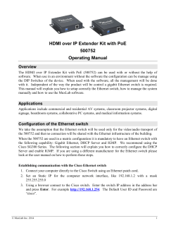
Figure 4 shows the block diagram for the Ethernet implementation in PL.
X-Ref Target - Figure 4
6RIWZDUH'ULYHU)RU/LQX[
6WDQGDUG1HWZRUNLQJ
$SSOLFDWLRQ
3URFHVVLQJ6\VWHP
8$57
0HPRU\
,QWHUIDFH
$38
7&3,36WDFN
(WKHUQHW'ULYHU
$;,'0$$;,(WKHUQHW
''5
&HQWUDO
,QWHUFRQQHFW
3/WR0HPRU\
,QWHUFRQQHFW
*,&
&ORFN
*HQHUDWLRQ
ELW*3
$;,0DVWHU
ELW+3$;,6ODYH
'HYLFH7UHH
$;,,QWHUFRQQHFW
$;,,QWHUFRQQHFW
$;,'0$
0+]
)&/.
5;
7;
ELW#0+]
'DWDSDWK
006
600
/LQX[,PDJH
$;,(WKHUQHW
*0,,ELW#0+]
%$6(;
3&630$
3URJUDPPDEOH/RJLF
*7;7UDQVFHLYHU
%$6(;,QWHUIDFH
6L
6)3
0+]*7
5HIHUHQFH&ORFN
;BB
Figure 4:
XAPP1082 (v3.0) January 7, 2015
PL Ethernet Design Block Diagram
www.xilinx.com
5
Using PL Ethernet
The HP port is used for fast data transfers between the PL and the PS DDR3 memory. It
connects to the AXI DMA scatter-gather, stream to memory mapped (S2MM), and memory
mapped to stream (MM2S) interfaces through the AXI interconnect. This interconnect also
performs data-width conversion to connect the 64-bit HP port to the 32-bit interfaces of AXI
DMA. In the AXI DMA, both the scatter-gather option and data realignment engine are enabled
for the S2MM and MM2S paths.
The streaming interface of the AXI DMA is connected to the AXI Ethernet IP. The AXI Ethernet
IP has full checksum offloading (CSO) enabled and has FIFO depths of 32K to support jumbo
frame transfers.
The AXI Ethernet IP is enabled in GMII mode, with the automatic I/O inclusion disabled. The
automatic I/O inclusion in the AXI Ethernet IP is disabled to prevent I/O buffer inclusion so that
another IP can be connected to these GMII ports within the FPGA. The AXI Ethernet IP is
connected to the 1000BASE-X IP through this GMII interface.
For the control interface, a general-purpose AXI master port is enabled in the PS. This port
connects to the AXI DMA and AXI Ethernet IP cores. The 1000BASE-X PHY registers are
accessed using the MDIO interface provided through the AXI Ethernet IP.
The interrupt ports from the AXI DMA and the AXI Ethernet IPs are connected to the general
interrupt controller (GIC) in the PS.
Note: For further details on the IP cores, see [Ref 3], [Ref 4], and [Ref 5].
Software Design
This section describes the software aspects of the design.
The monolithic Linux driver code facilitates the functionality listed here:
•
PL Ethernet MAC accesses
•
AXI DMA transfers
•
Physical media initialization for 1000BASE-X interface
XAPP1082 (v3.0) January 7, 2015
www.xilinx.com
6
About Device Trees
Linux Driver
Figure 5 shows the software architecture for the design.
X-Ref Target - Figure 5
8VHU/HYHO
SURFGHY
/LQX[.HUQHO
6FKHGXOHU
SURFLQWHUIDFH
GHYLQWHUIDFH
6RIW,54
'R,54
(WKHUQHW'ULYHU
'ULYHU0RGXOH
7UDQVPLW,65
5HFHLYH,65
'0$$FFHVV
0,,3+<
5HFHLYH
2YHUIORZ
7UDQVPLW
2YHUIORZ
7UDQVPLW
'0$
5HFHLYH
'0$
*0,,3+<
+DUGZDUH
*,&,QWU&RQWUROOHU
(WKHUQHW7UDQVPLW
'0$&KDQQHO
(WKHUQHW'0$
ILQLVKGRQHKDOW
HUURUHYHQWV
0,,,QWHUIDFH
;BB
Figure 5:
Driver Architecture for PL Ethernet
The driver is divided into these sections (see Appendix A for more information):
About Device
Trees
•
Initialization
•
MAC driver hooks
•
PHY timer
•
Interrupt service routines
The Device Tree is a data structure for describing hardware. Rather than hard coding every
detail of a device into an operating system, many aspects of the hardware can be described in
a data structure that is passed to the operating system at boot time. These settings are parsed
by the drivers at the time of loading and parameters are set as defined in the device tree.The
Linux drivers’ device trees consist of:
•
PS Ethernet MAC EMIO-specific: PS GEM1 section, containing PS MAC parameters.
•
PL Ethernet-specific:
•
XAPP1082 (v3.0) January 7, 2015
•
DMA section, containing AXI DMA parameters.
•
Ethernet section, containing the AXI Ethernet MAC parameters.
I2C section, containing Si5324 parameters. The Si5324 device is the reference clock
generator for the 1000BASE-X PHY transceivers.
www.xilinx.com
7
Hardware Requirements
Hardware
Requirements
Testing the design requires:
•
Standard PC, preferably running the Linux OS
•
Ethernet port supporting 1000 Mb/s
•
Netperf tool [Ref 6]
•
Zynq-7000 AP SoC ZC706 board with an SFP-to-RJ45 adapter module for testing
Figure 6 shows the board setup. Jumper J17 should be set to enable transmission through the
SFP. The design was tested with the HP 378928-B21 Cisco Gigabit Ethernet RJ45 SFP
Module.
X-Ref Target - Figure 6
;BB
Figure 6:
Ethernet
Performance
Board Setup
This section presents a summary of Ethernet throughput associated with the designs.
The performance of various Ethernet applications at different layers is less than the throughput
of the software driver and the Ethernet interface. This is due to the various headers and trailers
inserted in each packet by the various layers of the networking stack. Ethernet is used as a
medium to carry traffic. Various protocols, such as TCP/UDP, implement protocol specific
header/trailer formats.
CPU Affinity Considerations
In a multi-processor environment, CPU affinity is the ability of an OS scheduler to bind a certain
process to a given processor. The OS scheduler tries to schedule a process on the same
processor where it last executed. If the processor is not available, the process is scheduled on
a different processor.
XAPP1082 (v3.0) January 7, 2015
www.xilinx.com
8
Conclusion
Binding a process to a processor ensures that the process is always scheduled on the same
processor. The primary benefit of binding a process with a processor is optimal cache
performance, as it circumvents the invalidating of cache that is necessary each time a process
is scheduled on a different processor.
The CPU affinity of a process can be altered with the taskset program in Linux. For all
benchmarking results, netserver or netperf was bound to CPU2 using taskset. In this example,
binding netserver and netperf results in significant performance improvement:
zynq>
taskset 2 ./netserver
zynq> taskset 2 ./netperf –H <peer IP address>
For test methodology and performance observations, see
http://www.wiki.xilinx.com/Zynq+PL+Ethernet.
Conclusion
This application note provides designs for implementing the PS Ethernet through the EMIO
with PHY and Ethernet implementation in the PL to support multiple Ethernet links and jumbo
frames. Performance benchmarking results for the designs are included in this application note
(see http://www.wiki.xilinx.com/Zynq+PL+Ethernet).
The test results show a trend of throughput improvement with increasing packet size, and the
impact of CSO on both throughput and CPU utilization.
Reference
Design
The reference design files for this application note can be downloaded from:
https://secure.xilinx.com/webreg/clickthrough.do?cid=203511
Follow the instructions in the readme for building hardware and software code.
Table 1 shows the reference design matrix.
Table 1: Reference Design Matrix
Parameter
Description
General
Developer name
Xilinx
Target devices (stepping level, ES,
production, speed grades)
Zynq-7000 AP SoC
Source code provided
Yes
Source code format
Verilog, C
Design uses code/IP from existing
Xilinx application note/reference
designs, CORE Generator™ software,
or third-party
Yes
Simulation
Functional simulation performed
No
Timing simulation performed
No
Test bench used for functional and
timing simulations
No
Test bench format
N/A
Simulator software/version
N/A
SPICE/IBIS simulations
N/A
Implementation
XAPP1082 (v3.0) January 7, 2015
www.xilinx.com
9
Appendix A
Table 1: Reference Design Matrix (Cont’d)
Parameter
Description
Synthesis software tools/version
Vivado®
Implementation software
tools/versions used
Vivado® 2014.4
Static timing analysis performed?
No
2014.4
Hardware Verification
Hardware verified?
Yes
Hardware platform used for verification ZC706 board
Appendix A
PL Ethernet Linux Device Driver
This appendix provides information for the Linux PL Ethernet driver.
Initialization
When the driver is inserted into the kernel (using the insmod tool), the entry function is:
static int __init axienet_init(void)
{
platform_driver_register(&axienet_of_driver);
}
This in turn invokes the function:
static int __devinit axienet_of_probe(struct platform_device *op)
The probe function is the actual initialization function that performs these tasks:
•
Create the Ethernet driver structure alloc_etherdev().
•
Set up the Ethernet driver structure.
•
Map the physical device register address space into the kernel address space of_iomap().
•
Read the driver configuration properties from the device structure and set the driver flags
accordingly. The properties handled are:
•
TX CSO: xlnx, txcsum
•
RX CSO: xlnx, rxcsum
•
RX memory: xlnx, rxmem
•
MAC type: xlnx, temac-type
•
PHY type: xlnx, phy-type
•
DMA node: axistream-connected
•
MAC address: local-mac-address
•
Map the DMA register address space (physical) into Kernel address space of_iomap().
•
Get TX IRQ and RX IRQ numbers
•
Set MAC address
•
MDIO setup
•
Setup tasklets
XAPP1082 (v3.0) January 7, 2015
www.xilinx.com
10
References
MAC Driver Hooks
The MAC driver supports these handles to interface to upper layers:
•
Open: This driver open routine invokes PHY start, allocates ISRs, and enables the
interrupts and ISR handling. It also resets the AXI_DMA core and its buffer descriptors are
initialized. Additionally, it starts the network interface queues, PHY timer for poll routine.
•
Stop: This driver stop routine stops the PHY, removes the interrupt handlers, and disables
interrupts. AXI_DMA (RX and TX) is stopped and the descriptors are released. DMA
tasklet is disabled, network interface queues are stopped, and the PHY timer is removed.
•
Start_xmit: This routine is invoked from upper layers to initiate transmission of a packet. It
fetches next available descriptor, populate their fields, start transmission, by starting the
DMA transfer. It also considers the transmit CSO setting and accordingly populates
transmit descriptor user application fields.
•
Change_mtu: This hook is called to change the MTU size dynamically. It is used to
support jumbo frames.
•
Set_mac_address: This function changes the MAC address of the Ethernet core.
PHY Timer
This driver architecture does not use phylib to manage 1000BASE-X PHY, rather using timer
based PHY polling instead. PHY timer is a system timer that invokes a handle for every two
seconds. Its handle, poll_gmii, serves two purposes:
•
Keep the Ethernet MAC’s duplex setting in sync with the PHY setting.
•
Update the system with state of the link.
This routine accesses the PHY registers to get the current status of the duplex and link. If it
finds that the link is down, it immediately stops the interface and vice versa.
Interrupt Service Routines
The Linux driver has two interrupt service routines (ISR) as follows:
•
Receive ISR: Handles AXI DMA receive interrupts. It checks for the RX status; if the status
is OK, it processes the descriptors and passes them to interface for further process.
•
Transmit ISR: Handles AXI DMA transmit interrupt. It checks for the TX status; if the status
is OK, it clears the descriptors and unmaps corresponding buffers so that CPU can regain
ownership of the same. At the end, it invokes interface TX queue wake-up, so that
transmission can resume.
In case of an error status, ISR schedules the tasklet to reset the DMA and Ethernet services,
and reconfigures all transmit and receive descriptors. In-case interface TX queue was stopped
due to unavailability of free TX buffers in the transmit path.
References
This document uses the following references:
1. Si5324 Data Sheet, www.silabs.com/Support%20Documents/TechnicalDocs/Si5324.pdf
2. Zynq 7000 All Programmable SoC Technical Reference Manual (UG585)
3. LogiCORE IP Ethernet 1000BASE-X PCS/PMA or SGMII v11.5 (PG047)
4. LogiCORE IP AXI DMA v6.03a (PG021)
5. LogiCORE IP AXI Ethernet v3.01a (DS759)
6. Netperf, www.netperf.org
7. ZC706 Evaluation Board for the Zynq-7000 AP SoC XC7Z045 All Programmable SoC User
Guide (UG954)
8. 7 Series FPGAs GTX/GTH Transceivers User Guide (UG476)
XAPP1082 (v3.0) January 7, 2015
www.xilinx.com
11
Revision History
Revision
History
Notice of
Disclaimer
The following table shows the revision history for this document.
Date
Version
Description of Revisions
04/09/2013
1.0
Initial Xilinx release.
08/05/2013
2.0
Added last sentence under Hardware Requirements. Updated
example and note under CPU Affinity Considerations. Updated CPU
Affinity Considerations and Figure 7. Deleted Figure 8, “Impact of CSO
on PS GEM CPU Utilization”. Updated PL Ethernet: Throughput
Observation and Figure 8 and Figure 9. Updated Figure 10. Updated
ISE and PlanAhead versions from 14.4 to 14.6.
01/07/2015
3.0
Updated Figure 1, Figure 4, and Figure 6. Deleted last sentence
preceding Figure 6. Deleted note and performance-related information
(subsections “Test Methodology”, “PL Ethernet: Throughput
Observation”, and “Jumbo Frame Performance”) from Ethernet
Performance and added reference to test methodology and
performance observations wiki site. Updated ISE synthesis software
from ISE 14.6 to Vivado 2014.4 and PlanAhead version from 14.6 to
2014.4 in Table 1. Deleted Appendix A (PS EMIO Ethernet Device
Tree) and Appendix B (PL Ethernet Device Tree).
The information disclosed to you hereunder (the “Materials”) is provided solely for the selection
and use of Xilinx products. To the maximum extent permitted by applicable law: (1) Materials
are made available "AS IS" and with all faults, Xilinx hereby DISCLAIMS ALL WARRANTIES
AND CONDITIONS, EXPRESS, IMPLIED, OR STATUTORY, INCLUDING BUT NOT LIMITED
TO WARRANTIES OF MERCHANTABILITY, NON-INFRINGEMENT, OR FITNESS FOR ANY
PARTICULAR PURPOSE; and (2) Xilinx shall not be liable (whether in contract or tort,
including negligence, or under any other theory of liability) for any loss or damage of any kind
or nature related to, arising under, or in connection with, the Materials (including your use of the
Materials), including for any direct, indirect, special, incidental, or consequential loss or
damage (including loss of data, profits, goodwill, or any type of loss or damage suffered as a
result of any action brought by a third party) even if such damage or loss was reasonably
foreseeable or Xilinx had been advised of the possibility of the same. Xilinx assumes no
obligation to correct any errors contained in the Materials or to notify you of updates to the
Materials or to product specifications. You may not reproduce, modify, distribute, or publicly
display the Materials without prior written consent. Certain products are subject to the terms
and conditions of Xilinx’s limited warranty, please refer to Xilinx’s Terms of Sale which can be
viewed at http://www.xilinx.com/legal.htm#tos; IP cores may be subject to warranty and support
terms contained in a license issued to you by Xilinx. Xilinx products are not designed or
intended to be fail-safe or for use in any application requiring fail-safe performance; you
assume sole risk and liability for use of Xilinx products in such critical applications, please refer
to Xilinx’s Terms of Sale which can be viewed at http://www.xilinx.com/legal.htm#tos.
XAPP1082 (v3.0) January 7, 2015
www.xilinx.com
12


© Copyright 2026