
Data sheet PE 81.58
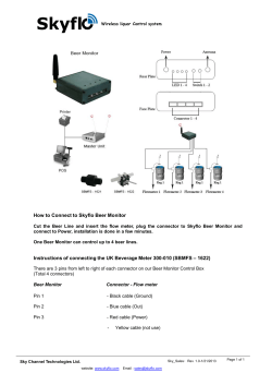
Electronic
pressure measurement
Pressure transmitter
For applications in hazardous areas
Model IS-3
WIKA data sheet PE 81.58
Applications
■■ Chemical, petrochemical industry
■■ Oil, natural gas
■■ Machine building
Special features
■■ Measuring ranges from 0 ... 0.1 to 0 ... 6,000 bar
■■ Approved for use in hazardous areas per ATEX and IECEx
■■ Suitable for SIL 2 per IEC 61508/IEC 61511
Pressure transmitter model IS-3
Fig. left: With angular connector with flush process
connection
Fig. centre: High-pressure version
Fig. right: With field case
Description
For the highest demands
The pressure transmitters of the IS-3 series are ideally suited
to applications in hazardous areas. These pressure transmitters have been specifically designed for the highest industrial
requirements and feature the ATEX and IECEx approvals as
well as a SIL rating.
The model IS-3 pressure transmitter is available with measuring ranges up to 6,000 bar and is suitable for applications
ranging from general machine building to high-pressure
applications in the LDPE production.
Design
All wetted parts are manufactured from stainless steel and
are fully welded. Internal sealing elements are completely
avoided, so that the unit can be used with nearly all media.
The robust case is also made of stainless steel and provides
a minimum ingress protection of IP 65. IP 68 versions are
also available.
WIKA data sheet PE 81.58 ∙ 01/2015
The process connections with flush diaphragm are particularly suitable for the measurement of viscous and contaminated
media and ensure trouble-free pressure measurement at all
times.
The optional field case of the model IS-3 enables operation in extreme environmental conditions and is resistant to
acids, bases, oils and solvents. Via the field case connection
integrated into the case's head, the electrical cabling can be
installed quickly and easily.
Voltage supply
It is recommended that the intrinsically safe variants of the
IS-3 series are powered via a suitable isolated barrier. An
ideal voltage supply is offered by the model KFD2-STC4-EX1
isolated barrier, see “Accessories”.
Page 1 of 15
Measuring ranges
Gauge pressure
bar
psi
Measuring range
Overpressure limit
Measuring range
Overpressure limit
Measuring range
Overpressure limit
Measuring range
Overpressure limit
Measuring range
Overpressure limit
Measuring range
Overpressure limit
Measuring range
Overpressure limit
Measuring range
Overpressure limit
Measuring range
Overpressure limit
0 ... 0.1
1.4
0 ... 2.5
8.3
0 ... 60
120
1,600 1) 2)
2,300
0 ... 3
20
0 ... 50
279
0 ... 300
1,200
0 ... 1,500
2,900
0 ... 8,000
17,400
0 ... 0.16
1.4
0 ... 4
19.3
0 ... 100
200
2,500 1) 2)
3,500
0 ... 5
59
0 ... 60
279
0 ... 400
1,200
0 ... 2,000
4,600
0 ... 10,000
17,400
0 ... 0.25
1.4
0 ... 6
41.4
0 ...160
320
4,000 1) 2)
5,000
0 ... 10
59
0 ... 100
600
0 ... 500
1,160
0 ... 3,000
7,200
0 ... 15,000
21,700
0 ... 0.4
4.1
0 ... 10
41.4
0 ... 250
500
5,000 1) 2)
6,000
0 ... 15
59
0 ... 150
600
0 ... 600
1,740
0 ... 4,000
7,200
0 ... 0.6
4.1
0 ... 16
82.8
0 ... 400
800
6,000 1) 2)
7,000
0 ... 20
120
0 ... 160
1,200
0 ... 750
1,740
0 ... 5,000
11,600
0 ... 1
4.1
0 ... 25
82.8
0 ... 600
1,200
0 ... 1.6
8.3
0 ... 40
80
0 ... 1,000 1)
1,500
0 ... 25
120
0 ... 200
1,200
0 ... 800
1,740
0 ... 6,000
11,600
0 ... 30
120
0 ... 250
1,200
0 ... 1,000
1,740
0 ... 7,500
17,400
0 ... 0.4
4.1
0 ... 10
41.4
0 ... 15
59
0 ... 0.6
4.1
0 ... 16
82.8
0 ... 30
120
0 ... 1
4.1
0 ... 25
82.8
0 ... 60
279
0 ... 1.6
8.3
0 ... 2.5
8.3
0 ... 100
600
0 ... 160
1,200
1) Only for instruments without flush process connection.
2) Only for instruments with ignition protection type Ex i. Not for instruments with SIL2.
Absolute pressure
bar
psi
Measuring range
Overpressure limit
Measuring range
Overpressure limit
Measuring range
Overpressure limit
Measuring range
Overpressure limit
0 ... 0.25
1.4
0 ... 4
19.3
0 ... 5
59
0 ... 200
1,200
0.8 ... 1.2
4.1
0 ... 6
41.4
0 ... 10
59
0 ... 300
1,200
Vacuum and +/- measuring ranges
bar
psi
Measuring range
Overpressure limit
Measuring range
Overpressure limit
Measuring range
Overpressure limit
Measuring range
Overpressure limit
-1 ... 0
4.1
-1 ... +9
41.4
-15 inHG ... 0
59
-30 inHG ... 100
600
-1 ... +0.6
8.3
-1 ... +15
82.8
-30 inHG ... 0
59
-30 inHG ... 160
1,200
-1 ... +1.5
8.3
-1 ... +24
82.8
-30 inHG ... 15
120
-30 inHG ... 200
1,200
-1 ... +3
19.3
-1 ... +5
41.4
-30 inHG ... 30
279
-30 inHG ... 300
1,200
-30 inHG ... 60
600
Other measuring ranges on request.
Output signal
Voltage supply
Analogue signal
4 ... 20 mA
Power supply U+
Model IS-3: DC 10 ... 30 V
Model IS-3 with field case: DC 11 ... 30 V
Permissible load in Ω
Model IS-3:
≤ (power supply - 10 V) / 0.02 A - (cable length in m x 0.14 Ω)
Power consumption Pi (for ignition protection type Ex i)
800 mW (for group III 750/650/550 mW)
Model IS-3 with field case:
≤ (power supply - 11 V) / 0.02 A
For the test circuit signal of the IS-3 model with field case a
load of ≤ 15 Ω applies
Page 2 of 15
WIKA data sheet PE 81.58 ∙ 01/2015
Reference conditions (per IEC 61298-1)
Temperature
15 ... 25 °C
Atmospheric pressure
860 … 1,060 mbar
Humidity
45 ... 75 % r. h., non-condensing
Mounting position
Calibrated in vertical mounting position with process
connection facing downwards.
Power supply
DC 24 V
Time response
Settling time
≤ 2 ms
≤ 10 ms, for medium temperatures below -30 °C
Accuracy data
Accuracy at reference conditions
Accuracy
Standard
Option
±0.50 % of span
±0.25 % of span 1)
1) Only for measuring ranges ≥ 0.25 bar and ≤ 1,000 bar
Including non-linearity, hysteresis, zero offset and end value
deviation (corresponds to measured error per IEC 61298-2).
Non-linearity (IEC 61298-2)
≤ ±0.2 % of span BFSL
Non-repeatability
≤ ±0.1 % of span
Mean temperature coefficient of zero point (0 ... 80 °C)
Measuring range ≤ 0.25 bar: ≤ ±0.4 % of span/10 K
Measuring range > 0.25 bar: ≤ ±0.2 % of span/10 K
Mean temperature coefficient of span (0 ... 80 °C)
≤ ±0.2 % of span/10 K
Long-term stability at reference conditions
≤ ±0.2 % of span/year
Adjustability of zero point and span
Adjustment is made using potentiometers inside the
instrument.
Zero point: ±5 %
Span:
±5 %
WIKA data sheet PE 81.58 ∙ 01/2015
Page 3 of 15
Process connections
Process connections, standard
Standard
Thread size
Max. nominal pressure (bar)
Overpressure limit (bar)
EN 837
G¼B
G½B
G⅜B
G¼A
G½A
¼ NPT
½ NPT
7/16-20 UNF BOSS
9/16-18 UNF BOSS
M20 x 1.5
R¼
R⅜
G¼B
G ½ B male / G ¼ female
M20 x 1.5 female with sealing cone
M16 x 1.5 female with sealing cone
9/16-18 UNF female F250-C
G ½ B flush
G 1 B flush
G 1 B flush, hygienic
1,000
1,000
1,000
600
600
1,000
1,000
600
600
1,000
1,000
1,000
1,000
1,000
6,000
6,000
6,000
600
1.6
25
1,400
1,800
1,400
600
600
1,500
1,500
600
600
1,800
1,600
1,400
1,000
1,400
15,000
10,000
10,000
600
10
50
DIN 3852-E
ANSI/ASME B1.20.1
SAE J514 E
DIN 16288
ISO 7
JIS B7505-76
-
Process connections for the optional medium
temperatures (see page 6)
Standard
Thread size
Max. nominal pressure (bar)
Overpressure limit (bar)
EN 837
G¼B
G½B
G¼A
½ NPT
R¼
G ½ B flush
G 1 B flush
G 1 B flush, hygienic
400
400
400
400
400
600 1)
1.6
25
800
800
600
800
800
600 1)
10
50
DIN 3852-E
ANSI/ASME B1.20.1
ISO 7
-
1) Restrictions dependent on sealing material, see table “Sealing material restrictions for
G ½ B flush process connection”
Sealings
Sealing material restrictions for G½ B flush process
connection
Process
connection
Material
Standard
Option
EN 837
DIN 3852-E
SAE J514 E
G ½ B flush
Copper
NBR 1)
NBR 1)
NBR 4)
Stainless steel
FKM/FPM (Viton) 2)
FKM/FPM (Viton) 2)
FKM/FPM (Viton) 4) or
FFKM (Kalrez) 4)
FKM/FPM (Viton) 2)
-
G 1 B flush
NBR 1)
G 1 B flush, hygienic EPDM 3)
1) Permissible temperature range: -20 ... +100 °C
2) Permissible temperature range: -15 ... +200 °C
3) Permissible temperature range: -40 ... +150 °C
4) See table “Sealing material restrictions for G½ B flush process connection”
Material Overpressure limit [bar]
T= -20 °C T= 80 °C
NBR
600
FKM/FPM 600
(Viton)
FFKM
600
(Kalrez)
T= 100 °C T= 120 °C T= 150 °C
600
600
600
600
N/A
400
N/A
300
600
600
600
600
T= Ambient temperature
N/A = Not applicable
Except for sealings for process connections per EN 837 the
sealings listed under “Standard” are included in the delivery.
Page 4 of 15
WIKA data sheet PE 81.58 ∙ 01/2015
Electrical connections
Available connections
see “Dimensions in mm”
For ignition protection type Ex nA
■■ Circular connector M16 x 0.75 acc. to IEC 61076-2-106
■■ Cable outlet IP 67 with protection cap
■■ Cable outlet IP 68 (continous use in the medium)
For ignition protection type Ex tc
■■ Cable outlet IP 67 with protection cap
■■ Cable outlet IP 68 (continous use in the medium)
For measuring ranges > 1,000 bar
■■ Angular connector acc. to DIN EN 175301-803 A
■■ Circular connector M12 x 1 acc. to IEC 61076-2-101 A-COD
■■ Cable outlet IP 67
■■ Field case
Reverse polarity protection
U+ vs. UInsulation voltage
DC 500 V
Specifications
Angular
connector acc. to
DIN 175301-803 A
Circular connector
M12 x 1 acc. to IEC
61076-2-101 A-COD
(4-pin)
Bayonet connector
Bayonet connector
Circular connector
acc. to MIL-DTL-26482 acc. to MIL-DTL-26482 M16 x 0.75 acc. to IEC
(6-pin)
(4-pin)
61076-2-106 (5-pin)
Connection diagram
3
1
4
3
2
1
2
3
Assignment (2-wire)
Cable shield
Wire cross-section
Cable diameter
U+ = 1
U- = 2
U+ = 1
U- = 3
4
2
5
U+ = A
U- = B
U+ = A
U- = B
U+ = 3
1
U- = 1
max. 1.5 mm²
6 ... 8 mm
Ship approval:
10 ... 14 mm
All cable outlets
Cable outlet IP 67 with Field case
protection cap
U+ = brown U- =
green
grey
0.5 mm²
6.8 mm
7.5 mm (variants for
continous use in the
medium)
U+ = brown U- = blue U+ = 1
Connection diagram
Assignment (2-wire)
Cable shield
Wire cross-section
Cable diameter
WIKA data sheet PE 81.58 ∙ 01/2015
Shield braid
0.34 mm²
5.5 mm
U- = 2
Test+ = 3
Test- = 4
5
max. 1.5 mm²
Cable gland
Nickel-plated brass: 7 ...13 mm
Stainless steel: 8 ... 15 mm
Plastic: 6.5 ... 12 mm
Page 5 of 15
Operating conditions
Ingress protection (per IEC 60529)
The ingress protection depends on the respective electrical
connection.
IP 65
■■ Angular connector acc. to DIN EN 175301-803 A
IP 67
■■ Circular connector M12 x 1 acc. to
IEC 61076-2-101 A-COD
■■ Circular connector M16 x 0.75 acc. to
IEC 61076-2-106
■■ Cable outlet IP 67
■■ Cable outlet IP 67 with protection cap
(precondition: avoidance of water accumulation
in the protection cap)
■■ Bayonet connector acc. to MIL-DTL-26482
IP 68
■■ Cable outlet IP 68 cable gland (72 h / 300 mbar)
Cable outlet IP 68 (continous use in the medium,
max. pressure 2 bar)
IP 69K ■■ Field case
Ignition protection types
■■ II 1G Ex ia IIA T4/T5/T6 Ga
■■ II 1/2G Ex ia IIC T4/T5/T6 Ga/Gb
■■ II 3G Ex ic IIC T4/T5/T6 Gc
■■ II 1D Ex ia IIIC T135 °C Da
■■ II 1/2D Ex ia IIIC T135 °C Da/Db
■■ I M1 Ex ia I Ma
■■ II 3G Ex nA IIC T4/T5/T6 Gc
■■ II 3D Ex tc IIIC T90 °C Dc
Vibration resistance
(in accordance with IEC 60068-2-6, vibration under
resonance)
■■ Model IS-3: 20 g
■■ Model IS-3 with field case and cable outlet IP 67 with
protection cap: 10 g
■■ Measuring ranges > 1,000 bar and optional medium
temperature ranges: 5 g
■■ Field case with optional medium temperature range: 2 g
Shock resistance
(per IEC 60068-2-27, mechanical shock)
■■ Model IS-3: 1,000 g
■■ Model IS-3 with field case: 600 g
■■ Measuring ranges > 1,000 bar, optional medium temperature ranges and cable outlet IP 67 with protection cap:
100 g
■■ Field case with optional medium temperature range: 50 g
Permissible temperature ranges for operation in accordance with the data sheet specifications (for ignition
protection type Ex i)
Medium
Standard
Option 1
Option 2
Option 3
Oxygen
■■ Ambient:
■■ Storage:
-20 ... +80 °C
-20 ... +150 °C (only for flush process connections and measuring ranges ≤ 600 bar)
-40 ... +150 °C (only for process connections with pressure port and measuring ranges ≤ 400 bar)
-40 ... +200 °C (only for process connections with pressure port and measuring ranges ≤ 400 bar)
-20 ... +60 °C
-20 ... +80 °C
- Cable outlet IP 68 (continous use in the medium), PUR cable: -15 ... +70 °C
- Cable outlet IP 68 (continous use in the medium), FEP cable: -15 ... +80 °C
-20 ... +80 °C
Permissible temperature ranges for operation in accordance with the data sheet specifications (for ignition
protection types Ex nA and Ex tc)
■■ Medium:
-15 ... +70 °C (with oxygen -15 ... + 60 °C)
■■ Ambient:
-15 ... +70 °C
■■ Storage:
-15 ... +70 °C
Maximum ambient and medium temperatures for safe operation, for medium temperatures ≤ 105 °C (for ignition
protection type Ex i)
94/9/EC (ATEX)
EPL
Group
Ambient and medium temperatures
(°C)
Temperature class / surface
temperature
1/2G
3G
Ga/Gb
Gc
IIC
-20 ≤ Ta ≤ +60
-20 ≤ Ta ≤ +70
-20 ≤ Ta ≤ +70
T6
T5
T4
Page 6 of 15
WIKA data sheet PE 81.58 ∙ 01/2015
Maximum ambient and medium temperatures for safe operation, for process connections with pressure port and
medium temperatures >105 °C (for ignition protection type Ex i)
Temperature class
Max. medium temperature (°C)
Max. ambient temperature (°C)
T2
200
195
175
155
135
130
110
105
40
45
50
50
50
50
50
50
T3
T4
Maximum ambient and medium temperatures for safe operation, for flush process connections and medium
temperatures >105 °C (for ignition protection type Ex i)
Temperature class
Max. medium temperature (°C)
Max. ambient temperature (°C)
150
135
130
110
105
20
50
50
50
50
T3
T4
Maximum ambient and medium temperatures (for ignition protection types Ex nA and Ex tc)
94/9/EC (ATEX)
EPL
Group
Ambient and medium temperatures (°C)
Temperature class /
surface temperature
3G
Gc
IIC
3D
Dc
IIIC
-15 ≤ Ta ≤ +55
-15 ≤ Ta ≤ +70
-15 ≤ Ta ≤ +70
-15 ≤ Ta ≤ +70
T6
T5
T4
T90 °C
The exact differentiation of EPLs and temperature ranges for safe operation is given in the operating instructions.
WIKA data sheet PE 81.58 ∙ 01/2015
Page 7 of 15
Materials
The materials used meet the requirements of the RoHS directive 2011/65/EC, except for the following device variants:
■■ Electrical output bayonet connector
■■ Measuring ranges > 1,000 bar
Wetted parts
Stainless steel, for sealing materials see “Process connections”
Non-wetted parts
■■ Case: Stainless steel
■■ Angular connector acc. to DIN EN 175301-803 A: PA6
■■ Circular connector M12 x 1 adjustable: PA6, stainless steel
■■ Circular connector M12 x 1 not adjustable: Stainless steel
■■ Circular connector M16 x 0.75 adjustable: PA6, stainless steel, Zn nickel-plated
■■ Circular connector M16 x 0.75 not adjustable: Stainless steel, Zn nickel-plated
■■ Bayonet connector adjustable: PA6, stainless steel, Al cadmium-plated
■■ Bayonet connector not adjustable: Stainless steel, Al cadmium-plated
■■ Cable outlet IP 67: PA6, stainless steel, nickel-plated brass
■■ Cable outlet IP 67 with protection cap: Stainless steel, PA66/6-FR
■■ Cable outlet IP 68 cable gland: Stainless steel, nickel-plated brass
■■ Cable outlet IP 68: Stainless steel
■■ Field case: Stainless steel, nickel-plated brass / stainless steel / PA
■■ Internal pressure transmission medium
- No oxygen application: Synthetic oil
- Oxygen application: Halocarbon oil
- Instruments with measuring range > 25 bar: Dry measuring cell
CE conformity
Pressure equipment directive
97/23/EC
EMC directive
2004/108/EC, EN 61326 emission (group 1, class B) and interference immunity (industrial application)
During interference consider an increased measuring deviation of up to 1 %.
ATEX directive
94/9/EC
Approvals
■■ IECEx, international certification for the Ex area
■■ SIL2, functional safety
■■ GL, ships, shipbuilding (e.g. offshore), Germany
Approvals, see website
Page 8 of 15
WIKA data sheet PE 81.58 ∙ 01/2015
Dimensions in mm
Pressure transmitter
Bayonet connector
acc. to MIL-DTL-26482
(4-pin) adjustable
Weight: approx. 0.2 kg
Bayonet connector
acc. to MIL-DTL-26482
(6-pin) not adjustable
Weight: approx. 0.2 kg
Circular connector M12 x 1
acc. to IEC 61076-2-101 A-COD
(4-pin) not adjustable
Weight: approx. 0.2 kg
WIKA data sheet PE 81.58 ∙ 01/2015
Bayonet connector
acc. to MIL-DTL-26482
(4-pin) not adjustable
Weight: approx. 0.2 kg
Cable outlet IP 67
adjustable
Weight: approx. 0.25 kg
Circular connector M16 x 0.75
acc. to IEC 61076-2-106
(5-pin) adjustable
Weight: approx. 0.2 kg
Bayonet connector
acc. to MIL-DTL-26482
(6-pin) adjustable
Weight: approx. 0.2 kg
Cable outlet IP 68
Cable gland
not adjustable
Weight: approx. 0.25 kg
Circular connector M16 x 0.75
acc. to IEC 61076-2-106
(5-pin) not adjustable
Weight: approx. 0.2 kg
Page 9 of 15
Angular connector
acc. to DIN EN 175301-803-A PG 9
adjustable
Weight: approx. 0.2 kg
Cable outlet IP 68 PUR
(continous use in the medium)
not adjustable
Weight: approx. 0.25 kg
Page 10 of 15
Angular connector
acc. to DIN 175301-803 A ½ NPT
adjustable
Weight: approx. 0.2 kg
Cable outlet IP 68 FEP
(continous use in the medium)
not adjustable
Weight: approx. 0.3 kg
Circular connector M12 x 1
acc. to IEC 61076-2-101 A-COD
(4-pin)
adjustable
Weight: approx. 0.2 kg
Cable outlet IP 68
Cable gland
adjustable
Weight: approx. 0.25 kg
WIKA data sheet PE 81.58 ∙ 01/2015
Cable outlet IP 68
Cable gland conduit ½ NPT
not adjustable
Weight: approx. 0.25 kg
Field case
Cable gland
adjustable
Cable outlet IP 67 with protection cap
not adjustable
Weight: approx. 0.25 kg
Field case
Conduit M 20 x 1.5-I
adjustable
Weight: approx. 0.3 kg
WIKA data sheet PE 81.58 ∙ 01/2015
Weight: approx. 0.3 kg
Field case
Conduit ½ NPT-I
adjustable
Weight: approx. 0.3 kg
Optional medium temperature ranges
-40 ... +150 °C and -40 ...+ 200 °C
Weight: approx. 0.45 kg
Page 11 of 15
Pressure transmitters with measuring range >1,000 bar
Angular connector
acc. to DIN EN 175301-803-A PG 9
adjustable
Weight: approx. 0.3 kg
Circular connector M12 x 1
acc. to IEC 61076-2-101 A-COD
(4-pin)
adjustable
Weight: approx. 0.3 kg
Cable outlet IP 67
adjustable
Weight: approx. 0.3 kg
Field case
Cable gland
adjustable
Weight: approx. 0.45 kg
Page 12 of 15
WIKA data sheet PE 81.58 ∙ 01/2015
Process connections
G
L1
G
L1
G
L1
G ¼ B EN 837
G ½ B EN 837
G ⅜ B EN 837
M20 x 1.5 DIN 16288
13
20
16
20
G ¼ A DIN 3852-E
G ½ A DIN 3852-E
14
17
¼ NPT
½ NPT
R¼
R⅜
13
19
13
15
G
L1
G
L1
7/16-20 UNF BOSS
9/16-18 UNF BOSS
12.06
12.85
G¼ B JIS B 7505-76
16
G1
G2
L1
L2
L3
G½B
G¼
20
15.5
13
Hygienic
G
L1
L2
L3
D1
G½B
23
20.5
10
18
WIKA data sheet PE 81.58 ∙ 01/2015
G
L1
L2
L3
D1
G
L1
L2
L3
D1
G1B
23
20.5
10
30
G1B
28
25
9
29.5
Page 13 of 15
Process connections for measuring ranges > 1,000 bar
G
L1
D1
G
L1
D1
M16 x 1.5
M20 x 1.5
12
15
4.8
4.8
9/16-18 UNF F250-C
11.2
4.3
Process connections for optional medium temperature ranges
-20 ... +150 °C
-40 ... +150 °C
-40 ... +200 °C
G
L1
L2
L3
L4
D1
G
L1
L2
G½B
G1B
23
23
20.5
20.5
10
10
15.5
15.5
18
30
G½B
20
71
For information on tapped holes and welding sockets, see Technical information IN 00.14 at www.wika.com.
Page 14 of 15
WIKA data sheet PE 81.58 ∙ 01/2015
Accessories and spare parts
Mating connector (for ignition protection type Ex i)
Designation
Order number
Angular connector DIN EN 175301-803 A
■■ with cable gland, metric, with 2 m moulded cable
■■ with cable gland, metric, with 5 m moulded cable
Circular connector M12 x 1
■■ angled version, 4-pin, IP 67, for self-assembly
■■ straight version, 4-pin, IP 67, for self-assembly
11225793
11250186
2421270
2421262
Sealings for mating connectors
Description
Order no.
Blue (Wika)
Brown (neutral)
Angular connector DIN 175301-803 A
1576240
11437902
Sealings for process connection
Process connection
Order no.
Copper
Stainless steel
NBR
FKM
G ¼ B EN 837
11250810
11250844
-
-
M20 x 1.5 DIN 16288
11250861
11251042
1537857
1576534
G ½ B EN 837
G ¼ A DIN 3852-E
G ½ A DIN 3852-E
11250861
-
11251042
-
-
1039067
-
1039075
Isolated barrier
Description
Order no.
Isolated barrier KFD2-STC4-Ex1
2341268
Ordering information
Model / Measuring range / Accuracy / Process connection / Sealing / Electrical connection / Temperature range of medium
© 2015 WIKA Alexander Wiegand SE & Co. KG, all rights reserved.
The specifications given in this document represent the state of engineering at the time of publishing.
We reserve the right to make modifications to the specifications and materials.
01/2015 EN
WIKA data sheet PE 81.58 ∙ 01/2015
Page 15 of 15
WIKA Alexander Wiegand SE & Co. KG
Alexander-Wiegand-Straße 30
63911 Klingenberg/Germany
Tel. +49 9372 132-0
Fax +49 9372 132-406
[email protected]
www.wika.de


© Copyright 2026