
SAP CRM (Customer Relationship Management
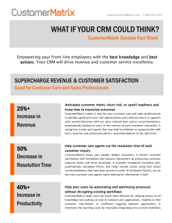
SAP CRM (Customer Relationship Management) Step-by-Step Tutorials Web Services and Document Templates in CRM o Creating Web Services in CRM (More details) o Creating Document Templates using Web Services in CRM (More details) o Transporting Web Services in CRM (More details) o Transporting Document Templates in CRM (More details) Creation of WEB UI Component and navigation with standard component (More details) NEW Few more tutorials related to CRM: Migrating Customer data along with relationships (CRM) using LSMW (More details) Configuration of CRM 7.0 Server with PI 7.0 (More details) Action Profiles in SAP-CRM (More details) Creation and configuration of Business Partners (More details) Adding Web URL (like google.com, yahoo.com) in CRM UI (More details) Configurations for opening an external URL (like SAP.COM) from IC WebClient. (More details) Difference between EEWB and BDT (More details) Creating Web Services in CRM By Vijender Sangwan Go to transaction BSP_WD_CMPWB Enter WS_DESIGN_TOOL as component and press TEST button. This will open the CRM Web UI in the new Browser. Click on the New Button to Create a New Web Service, which we will use for Document Templates . Enter the details as required. Enter the Component for which you want to create the Web Service. In this Case it is for Business Transactions: i.e.: Agreements for Grant Management. Choose the Root Object also as Business Transaction. Press the Next Button. One important thing here, don’t forget to click one of the Boxes at the end for Read, Create or Change. In this case we are creating a Web Service to read data from the database to read the Agreement details. Select Attributes Structure will open where you can select the data you want from the Structure to be fetched when the Web Service is called. Expand the Business Transaction Node and Select the data as shown below. Once a Node is selected, its attributes opens up on the Right Hand Side. Select the attributes like shown above as required. Once the Selection for a particular node is done, don’t forget to click on the Confirm Selection Button as shown under the attributes window. If this Button is not clicked the attirbutes will not be selected and will be lost, once you move ahead. Make sure form the BOL Browser you know which fields you need from the Web Services from which node for the Document Templates. Once the selection is done, click on the Next Button and it will take to the Maintain Attributes window, where we can review the fields. If any field is missed, Previous Button can be clicked and the field can be selected again. If there are some extra fields, that have been selected, click on the Radio Button Exclude in front of that screen and the field will be excluded from the selection. Once the Review is done fro all the fields, Press the Next Button. Click on the Expert Mode Button and you will see the details on the Right Side. Now Click on the Save Button. Once the Web Service is saved, Click on the Check Button to check for any errors or any issues with the Web Service. Once the Check is done, Press the Activate Button to Activate the Web Service. The activation take some time as all the Function Modules and other related components for a Web Service are created. Once it is Activated, Press the Productive Button. The Web Services is required to be made active to be available by other Services. Once the Web Service status changes to Productive, The Save Button is required to save the Productive state of the Web Service, else this state is lost and Web Service becomes Non Productive. The Web Service is now ready to be used for other services. Creating Document Templates using Web Services in CRM By Vijender Sangwan Log in to the Web UI and under the Administration tab. Select Document Templates. Click on the New Button to create a new Template The screen like above will be displayed to enter the details. Enter the details as shown above, File Type - Microsoft Word, as we are using Word Document template Name – Name of the Document Template Object type – BUS2000271, We have created the Web Service for Agreements, Choose as appropriate. Once the details are entered, click on start Designer A new word Document in editable mode is opened. Click on the Element showing in the bottom right Corner of the Window As you keep clicking it, it will take you into the Nodes you have selected in the Web Services. You can put them here in the window for display. Select all the fields you require for your Document .and design the document as required. Once the Document is designed. Click on the save Button to Save the Document. Once the document is saved, close the document. The document is now ready to be used. Transporting Web Services in CRM By Vijender Sangwan You need to perform following steps to use document templates in other clients or in Quality/Production system: 1) Web service created in one client will not be available in other clients by default. Create transport request for your web service via IMG->CRM-> UI framework -> UI framework definition -> Web services -> web service tool: transport service tools. Enter the name of Web Request and Press Execute The TR is created for that Web Service. TR for multiple Web Requests can be created together. 2) In test client/Quality system /Prod system, you need to get test client open for changes. Go to transaction WSCONFIG; find your web service definition and variant. Click on Create and save default values on next screen. 3) For Quality or Prod system, release and import TR Transporting Document Templates in CRM By Vijender Sangwan 1. Select document templates that you want to transport, using Customizing link SPRO => SAP Reference IMG => SAP Implementation Guide => Customer Relationship Management => Basic Functions => Content Management => Transport Document Template Or Run report 'CRM_KW_TEMPLATE_TRANSPORT' to select templates. Enter the Business Object of the Document Template and execute the Report. This will show all the Document Templates created for that Business Object. Press 'Transport' button after selecting the templates. You will be asked for correction request upon selecting 'Transport' button. Enter the transport request number that you have created. This operation adds logical and physical details of the template to Transport request. Go to transaction 'SE09' and release transport request or ask the Basis Administrator to release the TR. Go to target client in which you would like to import the template and run transaction 'SCC1' (Client Copy). Enter source client and transport request and press 'Start immediately to copy the request immediately. Otherwise press 'Schedule as Background Job' to run copy as background task. Creation of WEB UI Component and navigation with standard component By Narendra Goyal, L&T Infotech Introduction: This document provides the step by step procedure of creating Custom WEB UI Component and navigation of custom component with standard one and vice-versa. Prerequisite: Need the basic knowledge SAP CRM. At the end, you will be able to do: Creation of Custom WEB UI Component --BOL Programming Creation of view – Table view and Empty view --Creation of Windows Navigation between views and windows --Creation of link Component Controller --Custom Controller Assigning custom component to standard component component --Assigning standard component to custom Step 1. Creation of WEB UI Component. Go to SAP IMG Customer Relationship Management UI Framework UI Framework Definition Access BSP Component Workbench or transaction BSP_WD_CMPWB Enter component name (e.g. ZBP) in field component and click on create. Enter the description and window name (e.g. MainWindow) and click on continue. Choose a package and click on continue and provide workbench request. Your component will looks as given below. Step 2. Creation of view. In the component structure browser, right click on view and choose create. A wizard will be displayed. Enter the following data in wizard. Name – view name (e.g. PARTNERLINK) View Type – Empty View Do not change on following screens and finish the wizard. Similarly, create another view to display the data with the following data in wizard. Name – view name (e.g. PARTNER) Model Node – model node name (e.g. PARTNER) BOL Entity – BuilHeader Model Attribute – Select all by clicking on View Type – Table View Check the checkbox for configurable (For selecting displayed fields from available fields) and click on complete to finish the wizard. Step 3. Creation of Window. In the component structure browser, right click on window and choose create. A wizard will be displayed. Enter the window name (e.g. LINK). Do not change on the following screen and finish the wizard. Step 4. Maintain link in PARTNERLINK view Double click on PARTNERLINK view. In right hand side, double click on partnerlink.htm to maintain the link. For this write the given code. <%@extension name="htmlb" prefix="htmlb" %> <htmlb:link id = 'Select' text = 'My Accounts' onClick = 'ONCLICK' /> Step 5. Creation of outbound and inbound plug. Double click on PARTNERLINK view and in right hand side, right click on outbound plug and choose create. Give outbound plug name (e.g. TOLIST) Double click on OP_TOLIST method to implement. method OP_TOLIST. DATA: lr_window TYPE REF TO cl_bsp_wd_window. lr_window = me->view_manager->get_window_controller( ). lr_window->call_outbound_plug( iv_outbound_plug = 'TOLIST' ). endmethod. Double click on PARTNER view and in right hand side, right click on inbound plug and choose create. Give inbound plug name (e.g. FROMLINK). Double click on implementation DO_PREPARE_OUTPUT. class of PARTNER view and implement the method method DO_PREPARE_OUTPUT. DATA: lr_qs TYPE REF TO cl_crm_bol_query_service, result TYPE REF TO if_bol_entity_col, lr_col TYPE REF TO if_bol_bo_col, lr_result TYPE REF TO if_bol_bo_col, lr_prop_bp TYPE REF TO if_bol_bo_property_access, lr_param_ent TYPE REF TO if_bol_bo_property_access, lr_entity type ref to cl_crm_bol_entity. data: lv_bp type STRING, bp type bu_partner. data: lt_param type CRMT_NAME_VALUE_PAIR_TAB, lwa_param type CRMT_NAME_VALUE_PAIR, lt_attr type standard table of char120, lwa_attr type char120.. typed_context->PARTNER->build_table( ). CALL FUNCTION 'CRM_ERMS_FIND_BP_FOR_USER' EXPORTING IV_USER_ID = sy-uname IMPORTING EV_BUPA_NO = bp. lv_bp = bp. lv_bp = '404849'. "used constant business partner as no bp no. is assigned for this user lr_qs = cl_crm_bol_query_service=>get_instance( 'BuilHeaderSearch' ). lr_qs->set_property( iv_attr_name = 'PARTNER' iv_value = LV_bp ). result = lr_qs->get_query_result( ). lr_entity = result->get_first( ). if lr_entity is bound. result = lr_entity->get_related_entities( iv_relation_name = 'BuilContactPersonRel' ). endif. free lr_qs. lr_qs = cl_crm_bol_query_service=>get_instance( 'BuilHeaderSearch' ). clear: lv_bp, bp. refresh: lt_param. lr_param_ent = result->get_first( ). WHILE lr_param_ent IS BOUND. lv_bp = lr_param_ent->get_property_as_string( iv_attr_name = 'BP_NUMBER' ). IF lv_bp NE ''. lr_qs->set_property( iv_attr_name = 'PARTNER' iv_value = LV_bp ). lr_result = lr_qs->get_query_result( ). if lr_result is bound. typed_context->partner->collection_wrapper->add_collection( lr_result ). endif. ENDIF. lr_param_ent = result->get_next( ). clear: lv_bp, bp. ENDWHILE. endmethod. Save and activate. Double click on LINK window and in right hand side, right click on outbound plug and choose create. Give outbound plug name (e.g. TOLIST) Double click on OP_TOLIST method to implement. method OP_TOLIST. fire_outbound_plug( iv_outbound_plug = 'TOLIST' ). endmethod. Double click on MainWindow and in right hand side, right click on inbound plug and choose create. Give inbound plug name (e.g. FROMLINK). Step 6. Handling the event. Double click on PARTNERLINK view and in right hand side, right click on event handler and choose create. Give event handler name (e.g. ONCLICK) Double click on EH_ONONCLICK method to implement. method EH_ONONCLICK. OP_TOLIST( ). endmethod. Step 7. Select fields to display from available fields. Double click on PARTNER view. In right hand side select configuration tab. Click on EDIT. Provide the customizing request in the popup. Select the fields which you want to display in output from available fields into displayed fields. Refer from given below screen. Click on Save. Step 9. Adding custom component into standard component. I am adding custom component (ZBP) in standard component (WCC_SLS_HOME). Go to transaction BSP_WD_CMPWB In the field component enter a name for a standard component (e.g. WCC_SLS_HOME) and in field enhancement set enter a name enhancement set name (e.g. ZEH_SET). You can also create a new enhancement set by providing enhancement set name and click on create Enter the description and click on continue. Now click on display. Note: If you created a new enhancement set, then maintain enhancement set in cluster view (transaction SM34) BSPWDVC_CMP_EXT and in maintenance view (transaction SM30) BSPWDV_EHSET_ASG for respective client. Expand the view set WCC_SLS_HOME\SalesHome and navigate to the View Area, right-click on View Area and choose Add View. In the field View choose the view which you created (e.g. ZBP.ZBP/LINK). Click on continue. Expand the window and navigate to the main window, right-click on main window and choose Add View. In the field View choose the view which you created (e.g. ZBP.ZBP/MainWindow). Click on continue. Click on save. Step 10. Add custom component ZBP in configuration In component structure browser, double click on view SalesHome. Go to configuration tab and click on edit and provide customizing request. Select the custom component ZBP and click on move down button Now, if you test standard component WCC_SLS_HOME. It will show the LINK view as a part of view set. But currently if you click on link ‘My Accounts’ it will not work as navigation is still remaining. Step 11. Create Navigation Link. In runtime repository editor, right click on navigation link and select Add Navigation Link. Enter ID (e.g. ZBP), source view (e.g. ZBP.ZBP/LINK), outbound plug (e.g. TOLIST), target view (e.g. ZBP.ZBP/MainWindow) and inbound plug (e.g. FROMLINK). Click on continue. Click on save. Now, if you test standard component WCC_SLS_HOME. It will show the LINK view as a part of view set. Also when you click on link ‘My Accounts’ it will show you available buisness partners. Step 12. Creation of a field value as a link in table view. As shown in above screen shot, we will create buisness partner field as a link and on clicking on this, we are able to view details of buisness partner. Go to the custom component which you have created in step1 i.e. ZBP. In component structure browser double click on PARTNER view. In right hand side expand context node PARTNER. Go to the attribute BP_NUMBER and implement GET_P_BP_NUMBER method. method GET_P_BP_NUMBER. CASE iv_property. WHEN if_bsp_wd_model_setter_getter=>fp_fieldtype. rv_value = cl_bsp_dlc_view_descriptor=>field_type_event_link. WHEN if_bsp_wd_model_setter_getter=>fp_onclick. rv_value = 'SELECTION'. ENDCASE. endmethod. In PARTNER view, right click on outbound plug and choose create. Give plug name (e.g. TOPARTNER). Right click on custom controller and choose create. A wizard is displayed. Enter custom controller name (e.g. CUCOPARTNER), Model node (e.g. PARTNER), BOL Entity BuilHeader), add model attribute by clicking on and select all. Click on continue and finish the wizard. If prompted choose a package and enter workbench request. Double click on component controller and right click on context node and choose create. A wizard is displayed. Enter name (e.g. BPPARTNER), select radio button of model node and enter BOL Entity (BuilHeader), ), add model attribute by clicking on and select all. Do not change on the screens and finish the wizard. If prompted choose a package and enter workbench request. following Now right click on context newly created context node BPPARTNER and choose create binding. Enter BSP Application (e.g. ZBP), Controller type (Custom Controller), custom controller (CUCOPARTNER.do) and target context node (PARTNER). In component controller, right click on method WD_USAGE_INITIALIZE and choose redefine. Double click on the method to implement. method WD_USAGE_INITIALIZE. DATA: lv_usage TYPE REF TO if_bsp_wd_component_usage. lv_usage = me->comp_controller->get_component_usage( iv_usage->usage_name ). CASE iv_usage->usage_name. WHEN 'CUBP'. CALL METHOD lv_usage->bind_context_node EXPORTING iv_controller_type = cl_bsp_wd_controller=>co_type_component iv_target_node_name = 'BPPARTNER' iv_node_2_bind = 'PARTNER'. endcase. endmethod. In component structure browser, double click on PARTNER view and select the outbound plug method OP_TOPARTNER to implement. method OP_TOPARTNER. DATA: lr_tcc TYPE REF TO ZL_ZBP_BSPWDCOMPONENT_IMPL, " Implementation class of comp onent controller lr_cuco TYPE REF TO ZL_ZBP_CUCOPARTNER_IMPL, " Implementation class of custom contr oller lr_entity TYPE REF TO cl_crm_bol_entity, lr_cuwrp TYPE REF TO cl_bsp_wd_collection_wrapper, lr_window TYPE REF TO cl_bsp_wd_window, lv_guid TYPE bu_partner_guid, lr_core TYPE REF TO cl_crm_bol_core. lr_cuco ?= me->get_custom_controller( 'ZBP/CUCOPARTNER' ). CHECK lr_cuco IS BOUND. lr_cuwrp = me->typed_context->PARTNER->get_collection_wrapper( ). CHECK lr_cuwrp IS BOUND. lr_entity ?= lr_cuwrp->get_current( ). CALL METHOD lr_entity->get_property_as_value EXPORTING iv_attr_name = 'BP_GUID' IMPORTING ev_result = lv_guid. lr_core = cl_crm_bol_core=>get_instance( ). lr_entity = lr_core->get_root_entity( iv_object_name = 'BuilHeader' iv_object_guid = lv_guid CHECK lr_entity IS BOUND. lr_tcc ?= me->comp_controller. lr_tcc->typed_context->bppartner->collection_wrapper->clear_collection( ). lr_tcc->typed_context->bppartner->collection_wrapper-add( iv_entity = lr_entity iv_set_focus = abap_true ). view_manager->navigate( source_rep_view = rep_view outbound_plug = 'tobp' ). endmethod. Right click on event handler in PARTNER view and create the event handler (e.g. SELECTION). Implement the method EH_ONSELECTION. method EH_ONSELECTION. DATA: lv_index TYPE i. cl_thtmlb_util=>get_event_info( EXPORTING iv_event = htmlb_event_ex IMPORTING ev_index = lv_index ). me->typed_context->PARTNER->collection_wrapper->find( iv_index = lv_index ). op_TOPARTNER( ). endmethod. To test all scenarios, run the transaction CRM_UI. Click on My Accounts link. Click on business partner 404848 for detailed view. Migrating Customer data along with relationships (CRM) using LSMW By Srinivas, Infosys 1 Introduction This document provides a simple and user-friendly step-by-step approach for working with LSMW. The document mostly covers the practical usage of LSMW with respect to Batch input Recording Method. This document may be used to gain an insight of LSMW process in SAP CRM environment and may be used as a guide to help the consultants during the initial loading of master data into SAP database tables. 2 LSMW The Legacy System Migration Workbench (LSMW) is a tool that supports data migration from legacy systems (non-SAP systems) to SAP systems. It is a cross-platform component of the SAP system. The tool has interfaces with the Data Transfer Center and with batch input and direct input processing as well as standard interfaces BAPI and IDoc. The tool migrates user-defined datasets (known as objects), which are combined according to business criteria instead of individual tables or field contents. In addition to using standard import techniques, the user-specific objects can be generated. The LSMW supports a one-time transfer of data (initial data load) and also offers a restricted support of permanent interfaces. Thus, a periodic transfer of data is possible. The LSMW, however, does not include any functions for monitoring of permanent interfaces. The tool does not support any data export interfaces (outbound interfaces). Fig : LSMW-Process flow diagram 3 Creation of Project Hierarchy Use the Transaction Code LSMW to go to the initial screen. Create a project, corresponding subproject and object using Edit -> Create entry on menu bar. This is a hierarchy maintained in LSMW for all the data transfer done. Fig-01: LSMW - create project hierarchy Create a project, subproject and an object and click on continue. The following screen is displayed with the Project hierarchy details: Fig-02: LSMW- Initial screen Once the project Hierarchy is being created, an enumeration of steps for data migration is displayed as shown in Fig-03 below. This can be changed depending on the requirement of the user. For this “User Menu” tab in the tool bar needs to be clicked and all the necessary steps required for data transfer need to be selected. Fig-03: LSMW initial screen with user menu for selection of various steps. 4 Step by Step Process for uploading BP master data: The screenshot as in Fig-04 displays the fourteen steps required for loading Business partner data along with their relationships: Fig-04: Fourteen steps involved in LSMW The following pages describe each of those fourteen steps and key points to be remembered in each step. 4.1 Maintain Object Attributes In this step a Recording needs to be created (using GOTO -> Recordings overview in menu bar as shown in Fig-05) using Transaction code BP. Fig-05: Create Recording. Once recordings overview is clicked the following screen as in Fig-06 will be displayed. Enter a name and description to the recording. Fig-06: Enter details for the Recording. Enter the transaction for which the recording is to be done as shown in Fig-07 Fig-07: Transaction BP has been entered. Here the Business partner category needs to be chosen, under which the customers should be created. Click on Organization as shown in Fig-08: Fig-08: Click on Organization Select a Grouping and a Business Partner number in that Grouping and the role under which the customers needs to be created. Enter all the necessary details for business partner that needs to be loaded from the flat file: Fig-09: Shows Business partner number, Grouping and Role and other details entered. “External Grouping for loading the Customers and Accounts” has been used. Maintain relationships for the Business partner, as shown in fig-10 if relationships also need to be mapped from flat file. Fig-10: Displays three Relationships of BP number 1100. Once all the details have been entered save the Business Partner and click on back icon to go to recording that we created. Click on the fields displayed in orange color to change the name and default value of the fields. And let the other fields remain same whose values need to be defaulted to existing values. Fig-11: Displays the first screen of Recording ZRECORDC Fig-12: Displays the second screen of Recording ZRECORDC Fig-13: Displays the third screen of Recording ZRECORDC asking details for relationships. Now once recording is done, this is the first step of LSMW menu where the way or method of Import needs to be decided. There are generally four choices: 1. Standard Batch/ Direct Import Method - Direct insertion of data through Batch input programs. 2. Batch input Recording method - In this method a Recording of the transaction needs to be created which is later run as a Batch input Session. 3. Business object Method (BAPI) - Here the BAPI takes care of the data conversions and updating any database table. So the function module is responsible for the import of data into the system. 4. IDoc (Intermediate documents) - Here the data is written into an IDoc and passed to the LSMW to get it imported into the system. However This Document discusses the import of data through Batch input Recording Method. Fig-14: Choose the “Batch input recording” radio button and give the name of the recording that has been done earlier. Then save the object attributes. The LSMW system has to have the prior knowledge of what kind of data it is getting from the source that has to be imported into the system. For this reason the following three steps are very important that describe the structure of the files that has to be imported. 4.2 Maintain Source Structure Go to main menu in LSMW as shown in Fig-04 and click on second step: Maintain Source Structure and the following screen as in Fig-15 will be displayed: Click on create icon, enter a name and description to the source structure and click on continue. Then save the source structure and click on Back icon on the top of the screen. Fig-15: Entering details of source structure 4.3 Maintain Source Fields Go to LSMW Menu screen as shown in Fig-04 and Go to Third step: Maintain Source Fields. Select the source structure that was created and click on Table maintenance as shown in Fig-16 Fig-16: Maintain Source Fields Once Table Maintenance has been clicked, enter Field name, Data type and Length of all the fields under the required structure as it will appear in the input file. Even it is important to keep the sequence of the fields according to their position in the file. Give name to the fields and save it. Fields, that have constant value like Grouping, Role etc need not be maintained in this table and those fields need not be included in the flat file. Fig-17: Enter details of source fields and save Generally it is important to keep the data type and size of the fields same as that of the corresponding field in database table. However this might not be possible in all the cases, then the issue needs to be handled through the conversion routines. 4.4 Maintain Structure Relations Go to LSMW Menu screen as shown in Fig-04 and Go to Next step: Maintain Structure Relations. The following screen as shown in Fig-18 will be displayed. Save it and go to next step. Structure relations are the mapping between the structures we have declared in the previous steps with the recording done. However the one to one mapping of the fields will take place in the next step. Here only the high level correspondence is shown Fig-18: Structure relationship 4.5 Maintain Filed Mapping and Conversion Rules In the previous step the recording is mapped to the structure. There it automatically creates a one to one correspondence with the fields of both the sides and show in this stage as tree structure. Here each source field needs to be assigned to its corresponding target field in the recording side. A simple way to do this is to select the field from recording and press the tab “Assign source field” which will give a list of fields in the source structure and then select the filed that needs to be mapped to field in recording. Fig-19: Field Mapping-Initial Screen Fig-20: Field Mapping-Next Screen To maintain constant value to a field select that field in the recording and click on Constant (Ctrl+F9) Icon as shown in Fig-20 and a constant value can be assigned to that field. The following fields have been assigned constant values as displayed below: a. b. c. d. e. f. g. Grouping : 0002(PB Number Account & Customer –External) Role : 000000(Business partner-General) Time zone: PST Relationship category: FBUR001 Overview: A 4.6 Maintain Fixed Values, Translations, User-Defined Routines Here the conversion rules for processing project data need to be defined. The system generates the conversion program from the structure and field relationships as well as the conversion rules. Customization required for migration of data also needs to be specified here. That is, fixed values and translation values can be assigned and definite variants for the conversion rules can also be specified here. h. i. Fig-21: Maintain Fixed Values, Translations, User-Defined Routines j. 4.7 Specify Files k. Once the previous step of mapping each field to the source structure has been done, the next step is mentioning the file path to be selected for importing. l. m. Fig-22: Specify the path for the file etc. n. Here apart from the physical path, other attributes of the file that is to be imported also need to be specified. For example if it is a comma separated or tab delimitated file and if the file contains the field name as Start of File etc. o. There are other file-paths that can be mentioned, such as the file for imported data, converted data, etc. if necessary we can choose to change the existing file path that has been defaulted. p. 4.8 Assign Files q. Once the file has been specified as in previous step, this file needs to be assigned. r. So in this step select source structure and then click on save. s. Fig-23: Assign file t. 4.9 Read/Import Data u. Once assign the file has been assigned, next step is to execute the program as shown in Fig-24 to import the data from the file and put in the structure maintained earlier. For reference the test file that is imported is given below. This is a tab delimitated text file with header row. When it s run, the above program gives the output as in Fig-25. However the successful import data can also be seen from the main menu. v. w. Fig-24: Import / Read data x. y. Fig-25: Result of the execution of import program. 4.10 Display Read/Imported Data Once the data is imported, it can be displayed using this step. Once this step is selected and continue icon is clicked, system would display the following screen where all the imported data can be seen. Each row can be selected to see all the details of each customer. Fig-26: Display Imported/Read data 4.11 Convert Data Once the data is imported to the structure then go to the next step in the main menu that is- Generate conversion program, Convert data and display converted data. The first step generates the program that converts the data imported into the structure to the structure of Recording - ZRECORDC. This take care of all the conversion earlier mentioned. This step converts the data executing above program and store it in the filename given earlier. The result is shown as in Fig-27 & Fig 28. Also the converted data can be seen as in Fig-29. Fig-27: Convert Data Fig-28: Converted Data 4.12 Display Converted Data Once the data is converted, all the Converted data can be seen in this step. Once this step is selected and continue icon is clicked, system would display the following screen where all the Converted data can be seen. Each row can be selected to see more details of each customer. Fig-29: Display of Converted Data 4.13 Create Batch input session In this step a Batch input session needs to be created. For creating a Batch Input Session, Go to main menu in LSMW as shown in Fig-04 and click on next step: Create Batch input session and the following screen will be displayed. Click on execute. Fig-26: Intermediate screen showing the file path for creating Batch input Session. Once execute is clicked, system will display the following screen with the number of transactions (Business Partners) being created. Fig-26: Intermediate screen showing the number of transactions created. 4.14 Run Batch input session This is the final step where system processes the session to get all the data upload into the database through the given transaction (here BP- creating a Business Partner). For this it takes to the session over view screen as in Fig-27 and asks about the way of execution whether it should execute in the foreground or in the back ground. So select the line item and click on process icon on top. A new window pops up as shown. Then the type of processing mode needs to be selected. Processing mode Display errors only has been used which would display any errors encountered during creating business partners. Fig-27: Session overview and selection of Processing Mode. Once this step is processed, system will upload all the 450 Business Partners as in flat file into the respective database tables. In this document since BP transaction has been used, so it will create 450 Business Partners in SAP CRM Database tables. To see the Business Partner data updated in the system use Transaction SE16 and follow the steps as displayed in Fig-28, Fig-29 and Fig-30. Now all the business partners along with their relationship data can be seen that have been uploaded into the CRM System using Transaction BP. Fig-28: Transaction SE16 and enter table BUT000 Fig-29: Intermediate screen asking for certain criteria to display Business partners. Enter the criteria and click on execute. Fig-30: Business partners uploaded into SAP CRM Database tables. Configuration of CRM 7.0 Server with PI 7.0 By Praveen Kumar Kurni, Yash Technologies As CRM server produces BDoc instead of IDoc, this conversion takes place in XIF adapter which is inbuilt in CRM. But XIF (EXTERNAL INTERFACES) is nothing to do with PI/XI in particular. It is inbuilt in CRM which handles conversion part. I’m not discussing the steps that are required for conversion. Summery of Configuration details for both servers CRM and PI. CRM Server: Logical system name: SAPCRD SAP + CRD (System Name) RFC Destination : PICLNT001 (pointing to PI server) Port : SAPPID with RFC destination PICLNT001 Partner Profile : Partner No: LOGSYS001 (Logical system of PI) PI Server: Logical system name: LOGSYS001 RFC Destination : SAPCRD IDX1 : SAPCRD (Must be RFC destination: Probably Logical system name of CRM server) IDX2 : Maintained Configuration Steps: 1. RFC Destinations in CRM: Use TCode SM59 Provide the RFC Destination name preferably logical system name of the PI Server. RFC Destination: PICLNT001 Connection Type: 3 ABAP Connection Since we are connecting two SAP Servers we will go for this Connection type. Under Technical Setting provide the following: Target Host: pidev (Server Name) System No: 00 IP address: 10.80. . (Actual IP Address of the PI server) Gateway Host: pidev Gateway Service: sapgw00 (sap + gw + System No) How to find out Gateway Service for any Server? Open transaction SMGW and choose Go to -> Parameters -> Display. Beneath Attributes there will be the entries 'gateway hostname' and 'gateway service'. RFC Destination PICLNT001 in CRM Logon & Security: We provide the login details of the PI server. This facilitates the authentication to connect PI Server using particular RFC Destination: PICLNT001 Note: Beware with caps lock while providing password. If you test the connection with wrong password 3 times PI server gets locked for this user without your knowledge. 2. Port Configurations in CRM: Use TCode WE21 Select Transactional and press create on the menu. Provide the port name as SAPPID SAPPID SAP + PID (PI Development) Provide RFC destination which we create in TCode SM59 PICLNT001 3. Partner Profile: Use TCode: WE20 Select the Partner type LS and press create. Provide the following details Partner No: LOGSYS001 Partner Type: LS Under post processing permitted agent tab Ty. US (User) Agent: user name of CRM server Add the message type which you want to send from CRM to PI in outbound parameters table. Example: CRMXIF_PARTNER_SAVE_M Note: CRMXIF in the message type this is due to XIF inbuilt adapter available in CRM. Similarly add message type which you want to receive from PI in the Inbound parameters table Partner Profile: Outbound Parameters Provide the Receiver Port as SAPPID Port name that we defined in TCode WE21 Select the option Transfer IDoc immediately option. Provide the IDoc basic type for the message type. With that we finish configuring CRM server. Configurations in PI server: 1. RFC Destination in PI Server: Use TCode: SM59 RFC Destination: SAPCRD. Connection type: 3 ABAP Connection. Target Host name : crmdev IP Address: 10.80. . (Actual system IP Address of CRM Server) Gateway Host : crmdev System No: 00 Gateway service: sapgw00 Login/Security: Provide the Logon details of the CRM system. 2. Port: Use TCode: IDX1 Port: SAPCRD RFC Destination : SAPCRD Note: There should be only one port name that should be pointing CRM server with the system details. Q. What happens if you provide you own name instead of RFC name as port name? Please see handling error section of this tutorial. 3. Meta Data Overview for IDOC Adapter: IDX2 Customer Distribution Model in CRM system: BD67 Handling common errors shown in SM58 of CRM 7.0 while sending IDoc’s When we send IDoc from sender CRM server to PI server, error messages are issued in sending system (TCode SM58) for the function module IDOC_INBOUND_ASYNCHRONOUS. As we don’t configure any sender IDoc adapter in PI server this is where we resolve IDoc related issues in common. Let’s discuss common errors cause and solutions for the same. Error message: No service for system SAPCRD client 201 in the integration directory Cause: There is no service without party in PI server that represents CRM server with client details. Solution: We send IDocs from system CRD to PI. In the control record (Segment EDIDC40) of the IDoc, the SNDPOR (Sender Port) field contains the value "SAPCRD". The client of the sending system is determined by the MANDT field of the control record. The system ID and client are then used to determine a service without party of the type (business-system/business-service) In System Landscape Directory (SLD) create a technical system for CRD system and assign a client for the same. Don’t forget to assign an “ALE logical system” to the technical system created. Create a business system for this technical system. Then Business System can be imported under service without party/update the details existing in PI. Error message. Transaction IDX1: Port SAPXYZ, client 201, RFC destination Solution: The Integration Server tries to load the IDoc metadata from the sending system. Standard IDoc schemas from the Integration Repository cannot be used because they are release-dependent. As we discussed above Integration Server is determined by the value of the “SNDPOR” field from the IDoc control record. We will create a port in IDX1 in Integration Server, which is similar to that of the RFC Destination created in CRD. This must be unique and matching with RFC destination in CRD (for ex: SAPCRD) please avoid common names like RFCTOPI, RFC2PI. This implies sender RFC destination in CRD and Port in Integration Server should be same. Then it can import the IDoc metadata from the sending system using the “SNDPOR” field neglecting the standard IDoc schema that got imported in to PI. Error message: "::000" This error occurs if the central XI system tries to load the IDoc metadata from the sending system by RFC. But there might be several reasons for this error. Error is not transferred in full by the tRFC completely, so we get the above incomplete error. Possible reasons for the above error: 1. 2. 3. user login fails for the sending system; Authentication failure for user login. IDoctyp/Cimtyp cannot be loaded. Check for the user login details and also which client is used for login. Check with system administrator and assign necessary roles for the user. Verify IDoc type in TCode : WE30 whether New IDoc segments added are released. Segments that no longer exist in IDoc should be removed. Data elements that do not exist in the DDIC are assigned to fields in the segment. Error message: NO_EXEC_PERMISSION: "User" "Business System" Solution: ‘User’ is not in the list of Users list created in the directory who are authorized to use ‘Business System’ 1 INTRODUCTION 1.1 ACTIONS Actions are used in maintaining and improving business relationships. We can schedule and start predefined conditions with the Actions component by means of user-definable conditions from transaction and marketing objects. Actions use the Post Processing Framework (PPF), a Basis component, which can be automated with the initiation of outputs, follow-on documents or workflows. Using the Actions tab page within a business document, you can display a list of actions that can be included in the business transaction. An action profile is determined from the corresponding transaction type or item category. Actions are stored as action definitions within an action profile. You can control action processing using different settings and parameters: Action changeable or executable in dialog Action displayed in toolbar (SAP GUI) Processing time (when saving the document or via selection report) Partner dependence Determination technique Action merging Processing types (with entry of the desired form name) 1.2 FEATURES OF ACTIONS You can define actions dependent on conditions so that the system automatically schedules and starts them when the conditions are fulfilled. With actions you can: Create follow-up transactions automatically Execute changes in the transaction or marketing object currently being processed, for example, create new items, or status inheritance by subordinate elements in marketing objects Output in print, by faxing or e-mail Actions are displayed in transaction documents that support actions and to which an action profile is assigned. You can display a list of actions scheduled for the document on the Actions tab page of a transaction document. The following information is displayed in the list for each action: Status (action scheduled, action processed) Description (purpose of action) Conditions (settings for action definition and conditions are displayed) Creator, Creation date There are various processing types for actions: Methods (Business Add-Ins) Methods are Business Add-In (BADI) implementations. You can define your own BADI implementation to adapt actions to your processes and needs. (EXEC_METHODCALL_PPF is the relevant BADI.) Examples for standard methods include the following: COPY_DOCUMENT (create a follow-up document) COMPLETE_DOCUMENT (set status completed within document) CREDIT_MEMO (create credit memo item) REPAIR_ITEM (create a repair item) 1O_EVENT_CREATE (create a workflow event) SAP Business Workflow This is suitable for more complex processes, for example, a follow-up transaction that includes an approval process. Smart Forms SAP Smart Forms must be used to print, e-mail or fax documents such as an order confirmation. You can use the graphics tool, SAP Smart Forms, to design the layout of output forms. SAP delivers several Smart Forms for outputs in SAP CRM: Form CRM_ORDER_CONFIRMATION_01 (suitable for faxes, letters, and e-mail) Form CRM_ORDER_LEASING_01 (suitable for faxes, letters, and e-mail) Form CRM_OPPORTUNITY_01 (suitable for faxes, letters, and e-mail) SAP Smart Forms offer the advantage of adapting forms without requiring programming knowledge, thanks to a completely graphical user interface. When you request a printout of a form, the application program obtains the relevant data to be used and prints it on the form. Data retrieval and form logic are separated from one another. SAP Smart Forms replace SAP-Script forms (migration from SAP-Script forms to Smart Forms is supported). 2.0 HOW TO CREATE AN ACTION 2.1 STEP-BY-STEP PROCEDURE 2.1.1 Enter into any SAP-CRM Server and move to Transaction SPRO. 2.1.2 Press SAP Reference IMG -> Customer Relationship Management ->Basic Functions -> Actions -> Actions in Transactions. 2.1.3 To create an Action Profile – Click on documentation. 2.1.4 Now Press the Execute Button to start creating an Action Profile. . First read the 2.1.5 Click . Enter the Details to create Action Profile. 2.1.6 Click . Enter the Details to create Action. 2.1.7 Click . Enter the Details to set Action. In the Processing Time Details, there are 3 Options. Processing Using Selection Report gets started after a selection report is executed if the start condition has been fulfilled. Immediate Processing gets started as soon as the start condition is fulfilled. Processing when saving a Document gets started when the document is saved. 2.1.8 Click . Enter the Details to Set Up Partner Determination. Partner Dependent makes this Action as dependent on Partner. The partner you choose is the one, for which the action triggers. It first checks whether that Partner exists or not. If not, it throws an ERROR. 2.1.9 Click and select the Processing. The processing that we select is the one on which we want the Action to work on. Processing can be of various types such as:- Select the one you want. For this case select Workflow. 2.1.10 Click and Enter the Workflow Number that you want to assign with this Action. 2.1.11 Click and Enter Action Description. 2.1.12 Click and assign Schedule Condition. Schedule Condition decides whether an action should be scheduled for processing or not. An action is therefore generated only if the schedule condition is met. It is not mandatory to assign a schedule condition. Select anyone that suits your requirement and proceed further. 2.1.13 Click and assign Start Condition. Start Condition is checked before an action is executed. The Action is executed only if the Start Condition is satisfied. Here you won’t be able to assign a Start Condition; there is another tab in Actions where we can assign Start Condition. 2.1.14 Click and Action Configuration is complete. Click and save it in a Transport Request. 2.1.15 To assign Start Condition -> Go-to step 2.1.2 -> Click on Change Actions and Conditions -> Define Conditions. In Scheduling of Actions, find your Action – Test an Action Profile. It shows you the entire Action that you created till now. To assign start condition, Click on Start Condition Tab. Click Edit Condition to enter a condition. Enter a Condition. Click ‘√’. Click on SAVE. Save it in the same Transport Request as Earlier. And hence, this completes your Action Profile Creation for a Workflow. Similarly, we can create Action Profiles for other processing also. Creation and Configuration of Business Partners By Krishna Prathyusha Jataprolu, Accenture Introduction This document is the Business Process Design of the Business Partner Master data for SAP CRM. It describes the interpretation of the SAP CRM object Business Partner (abbreviated BP). Objectives The aim of this document is to acquire all information needed for the customizing object BP in SAP CRM. Business Partner Defining Number Range In this activity, you define number ranges for business partners. The defined number ranges are assigned to groupings in the Define groupings and assign number ranges activity. Number ranges for business partners are valid throughout a client. Procedure 1. Access the activity using one of the following navigation options: 1. SAP CRM Role Menu Transaction code IMG Path 2. Choose Change Intervals 3. Choose Insert Interval. Defining Number Range for Org Business Partners SPRO Cross-Application Components à SAP Business Partner à Business Partner Basic Settings Number Ranges and Groupings Define Number Ranges 4. Enter the Interval ID and range 5. Select Check Box Ext if External Number range is required 6. Save your Entries Result: The Number ranges are defined as needed for different kinds of roles of Business Partner. Defining Groupings Use Assign each business partner to a grouping when you create the business partner. This grouping determines the number range. You cannot change this assignment at a later stage. Procedure 1. To carry out the activity, choose one of the following navigation options: SAP CRM Defining Groupings Transaction code IMG path CRM Cross-Application Components SAP Business Partner SPRO Business Partner Basic Settings Number Ranges and Groupings Define Groupings and Assign Number Ranges 2. Choose New Entries. 3. Enter the grouping, short name, description, number range and select the check box External. 4. Save your entries. Result: All the Number Ranges defined are assigned to a group with a particular naming convention, which are used in Grouping Tab in Easy Access Screen of Business Partner. Defining Business Partner Roles Definition: Business Partner role Rights and responsibilities that a business partner can have in various business transactions. In this activity, you make the settings for the properties of business partner roles. In the business partner dialog you can select from all of the business partner roles provided. If you only want to display certain business partner roles in the selection list, you can hide the other business partner roles. You can replace the standard title of business partner roles with customer-defined names Procedure 1. To carry out the activity, choose one of the following navigation options SAP CRM Transaction code IMG path Defining Groupings SPRO CRM Cross-Application Components SAP Business Partner Business Partner Basic Settings Business Partner Roles Properties of Business Partner Roles 2. Select New Entries. 3. Select the required Business Partner Role. 4. 5. 6. Set the indicator Hide if the business partner role is not to appear in the selection list. Define the position where the business partner role is to appear in the selection list. If you want to give the selected business partner role a different title to the standard title, enter the required Customer title under Title. 7. Save your Entries 8. The following roles will be used in SAP CRM: 9. Role Name Category (Person/Org/Group) Employee Person Remarks Use of Standard role Employee Contact person Person Use of SAP standard role contact person Sold to Parry Person/Organization Use of SAP standard role sold-to party Prospect Person/Organization Use of SAP standard role prospect Ship to Party Person/Organization Use of SAP standard role Ship to Party Bill to Party Person/Organization Use of SAP standard role Bill to Party Retailer Person/Organization This role will be used to register the retailers. 10. Result. 11. All the Business Partner roles those the client wants to appear in the Easy access Screen are defined and all those that are unwanted are hidden. 12. The Business Partner Roles are named in accordance with the client’s requirement. 13. Creating a Business Partners 14. Procedure 15. 1. Access the activity using one of the following navigation options: SAP CRM Role Menu Transaction code SAP Menu 16. 2. Checking Business Partners BP Master Data Business Partner Maintain Business Partner Go To create Person 17. 18. In the field display Role Choose sold to party and in Grouping Choose Customers Grouping 19. 3. Enter all the required data, like Title, Name, Address and also the data as required the other tabs 20. 21. 4. Save the entriy. 22. 5. Repeat the same for different roles. 23. Result. 24. Business Partners are created with required roles. 25. Adding Web URL (like google.com, yahoo.com) in CRM UI 26. By G.Vijayalakshmi, Accenture 27. Web URL (E.g. Google, Yahoo, etc) in CRM UI can be launched using transaction launcher 28. Step1: 29. Step1a: Call Transaction SM30. Enter the View name: CRMV_IC_LTX_URL 30. 31. Step1b: 32. URL ID: ZGOOGLE (any name starting with Z) 33. Description: Google 34. Request Method: Get 35. Click radio-button 36. URL: for Non-BSP URL http://www.google.com 37. 38. Save the entry. 39. Step2: 40. Step2a: 41. Call transaction CRMC_UI_ACTIONWZ 42. Or 43. IMG path CRM -> UI Framework -> Technical Role Definition -> Configure Transaction Launcher 44. 45. 46. Step2b: 47. Launch Trans. ID : Zlaunch_google.(Any name starting with Z) 48. Component Set 49. Click on Continue. : ALL 50. 51. Step2c: 52. Description : launch google 53. Class name : ZCL_CRM_LAUNCH_GOOGLE (Any class name starting with Z). 54. Activate checkbox for ‘Stateful’ to show the URL in a new window. 55. Be sure that the checkbox ‘Raise Veto’ is deactivated. 56. Click on Continue 57. 58. 59. Step2d: 60. Choose URL Transaction (B) as transaction type 61. URL ID: ZGOOGLE created in the URL repository. 62. Continue 63. 64. Step2e: 65. 66. Skip screen for transaction parameters and activity clipboard by pressing ‘Continue’. End the wizard and press ‘Complete’. 67. Step3: 68. Step3a: 69. Execute Transaction CRMC_UI_NBLINKS 70. Or 71. IMG path CRM -> UI Framework -> Technical Role Definition -> Define Navigation Bar Profile 72. 73. Select ‘Define Logical Links’ at the dialog structure on the left by double-click. 74. Create a new logical link: 75. Logical Link ID: ZGOOGLE 76. Type: Launch Transaction 77. Target ID: EXECLTX 78. Parameter ZGOOGLE 79. Parameter Class: CL_CRM_UI_LTX_NAVBAR_PARAM 80. Title: Google 81. Description: Google 82. 83. Save the changes. 84. Step3b: 85. Select ‘Define Direct Link Groups’ 86. Create a new entry 87. Group ID : ZGOOGLE 88. Group Type : No Classification 89. Title : Google 90. Description : Google. 91. 92. Step3c: 93. Select ‘Assign Links’ at the dialog structure on the left by double-click. 94. Create a new entry 95. Logical link ID : ZGOOGLE (Which has been defined in Define Logical Links) 96. Position : 10 97. Save the changes. 98. 99. Add the link which was created in Define Logical Links. 100. 101. Step3d: 102. Select ‘Define Profile’ 103. Select profile corresponding to web UI 105. Click ‘Assign Direct Link Groups’ at the dialog structure on the left 106. Create a new entry 107. Group ID : ZGOOGLE 108. Position 104. : 30 (any position). 109. 110. Step4: Execute Transaction CRMC_UI_PROFILE or go to IMG path CRM -> Business Roles -> Define Business Role. 111. 112. Select business role ZWOOSALESPRO (the role which is assigned to user) 115. Double-click on ‘Visible Direct Group Links’ at the dialog structure on the left. 116. Click Visible Check Box corresponding to Group ID ZGOOGLE 113. 114. 117. 118. Step5: In the Web UI the link appears as shown below. 119. Configurations to open an external url (like SAP.com) from IC WebClient Web URL inside CRM IC Web BSP view can be launched using transaction launcher. Follow the steps below: First create URL ID using the path IMG->CRM->IC WebClient->Basic Functions->Transaction Launcher->Define URL's and Parameters Here by clicking on New Entries ,you need to create a URL ID, select 3rd radio button Non BSP URL and enter your web URL there. To keep it simple copy the existing URL ID SAP into your own with your web URL for ex ZSDN Now go back to Transaction Launcher and start the "Configure Transaction Launcher" Wizard In the Wizard when it prompts for Launch Transaction ID ,enter new transaction ID for ex ZTXID_SDN and click on 'continue ' and enter transaction class name for ZCL_TX_SDN In the next screen under 'Transaction launcher Type' select 'URL Transaction' ,and under details area select the URL ID you have created in step 1. i.e ZSDN. Complete the wizard. Now you need to map the URL transaction ID to Navigation Bar profile entries. For this go to 'Define Navigation Bar Profiles' under Basic Functions. Click on Define Entries ,enter the basic details and select 'Launch Trans' radio button and select the transaction id created in step 2 . i.e ZTXID_SDN Add the above create entry to your Navigation Bar profile Update IC Web Client profile with your Navigation bar profile Launch IC web and you would see Web URL Navigation bar entry under Navigation Bar. Difference between EEWB and BDT BDT, among other things, is used to add/delete/disable fields in the BP transaction only. It does not create new objects for the developer to play with. BDT as a separate unit in CRM (TCode BUPT) has several useful tools like BP events which are useful at times. Whereas EEW can extend several transactions in CRM including BP and it extends the business object by creating several z-objects like an active BADi implementation, middleware objects like z-function modules which you can use for coding your custom logic. But there's a lot in common for BDT and EEW - they both create the field groups, views, sections and screens when you enhance an object. You can use BDT to change titles such as tab name or section name after you have created the easy enhancement project for a particular object!


© Copyright 2026